US11114792B2 - Contact and connector - Google Patents
Contact and connector Download PDFInfo
- Publication number
- US11114792B2 US11114792B2 US16/721,985 US201916721985A US11114792B2 US 11114792 B2 US11114792 B2 US 11114792B2 US 201916721985 A US201916721985 A US 201916721985A US 11114792 B2 US11114792 B2 US 11114792B2
- Authority
- US
- United States
- Prior art keywords
- upper wall
- contact
- lance
- rear end
- wall
- Prior art date
- Legal status (The legal status is an assumption and is not a legal conclusion. Google has not performed a legal analysis and makes no representation as to the accuracy of the status listed.)
- Active
Links
Images



Classifications
-
- H—ELECTRICITY
- H01—ELECTRIC ELEMENTS
- H01R—ELECTRICALLY-CONDUCTIVE CONNECTIONS; STRUCTURAL ASSOCIATIONS OF A PLURALITY OF MUTUALLY-INSULATED ELECTRICAL CONNECTING ELEMENTS; COUPLING DEVICES; CURRENT COLLECTORS
- H01R13/00—Details of coupling devices of the kinds covered by groups H01R12/70 or H01R24/00 - H01R33/00
- H01R13/02—Contact members
- H01R13/10—Sockets for co-operation with pins or blades
- H01R13/11—Resilient sockets
- H01R13/113—Resilient sockets co-operating with pins or blades having a rectangular transverse section
-
- H—ELECTRICITY
- H01—ELECTRIC ELEMENTS
- H01R—ELECTRICALLY-CONDUCTIVE CONNECTIONS; STRUCTURAL ASSOCIATIONS OF A PLURALITY OF MUTUALLY-INSULATED ELECTRICAL CONNECTING ELEMENTS; COUPLING DEVICES; CURRENT COLLECTORS
- H01R13/00—Details of coupling devices of the kinds covered by groups H01R12/70 or H01R24/00 - H01R33/00
- H01R13/40—Securing contact members in or to a base or case; Insulating of contact members
- H01R13/42—Securing in a demountable manner
- H01R13/428—Securing in a demountable manner by resilient locking means on the contact members; by locking means on resilient contact members
- H01R13/432—Securing in a demountable manner by resilient locking means on the contact members; by locking means on resilient contact members by stamped-out resilient tongue snapping behind shoulder in base or case
-
- H—ELECTRICITY
- H01—ELECTRIC ELEMENTS
- H01R—ELECTRICALLY-CONDUCTIVE CONNECTIONS; STRUCTURAL ASSOCIATIONS OF A PLURALITY OF MUTUALLY-INSULATED ELECTRICAL CONNECTING ELEMENTS; COUPLING DEVICES; CURRENT COLLECTORS
- H01R13/00—Details of coupling devices of the kinds covered by groups H01R12/70 or H01R24/00 - H01R33/00
- H01R13/40—Securing contact members in or to a base or case; Insulating of contact members
- H01R13/42—Securing in a demountable manner
- H01R13/422—Securing in resilient one-piece base or case, e.g. by friction; One-piece base or case formed with resilient locking means
Definitions
- the present invention relates to a contact and, more particularly, to a contact having a lance.
- a contact of a connector can have a lance.
- the lance has a fixed end at the front of a direction of insertion of the contact into a connector housing and a cantilever shape that extends rearward.
- the lance has a free end at the rear and an engaging portion that engages with the connector housing.
- An electric wire for example, can be connected to the contact. When a rearward pull-out force is applied to the electric wire, the engaging portion abuts against the connector housing and prevents the contact from being pulled out.
- the electric wire for example, can easily get under the lance from the free end, and the electric wire under the lance may snag on the lance and cause accidental deformation of the lance.
- Japanese Patent No. 3-147282A discloses a contact having a structure in which a free end of a lance is extended to be positioned under an upper wall of the contact. This structure prevents an electric wire or the like from getting under the lance, thus reducing accidental deformation of the lance.
- the lance is formed by folding back rearward a beam that extends forward from an upper wall of the contact. Consequently, the yield of a material of contacts is low and only a small number of contacts can be produced per unit area of a plate of the material.
- a contact includes a pair of side walls, a front end upper wall extending from the side walls, a rear end upper wall extending from the side walls, a lance extending in a rearward direction from a rear end of the front end upper wall, and an extension piece extending in the rearward direction from a rear end portion of the lance.
- the lance has a catch portion at the rear end portion of the lance. The catch portion is caught in a housing when the contact is inserted into the housing.
- the extension piece is positioned under the rear end upper wall.
- FIG. 1A is a front perspective view of a contact according to an embodiment
- FIG. 1B is a rear perspective view of the contact of FIG. 1A ;
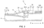
- FIG. 2 is a sectional side view of the contact, taken along line Z-Z of FIG. 1A ;
- FIG. 3A is a front view of the contact of FIG. 1A ;
- FIG. 3B is a side view of the contact of FIG. 1A ;
- FIG. 3C is a rear view of the contact of FIG. 1A .
- FIGS. 1A and 1B A contact 10 according to an embodiment is shown in FIGS. 1A and 1B .
- the contact 10 has an electric wire connecting terminal, located at a rear R, that is connected to an electric wire.
- the contact 10 is inserted into a connector housing in a frontward direction F.
- the contact 10 has a bottom wall 11 , a pair of side walls 12 A, 12 B, and a pair of upper walls 13 A, 13 B on top of each other.
- the pair of side walls 12 A, 12 B include a right side wall 12 A and a left side wall 12 B.
- the pair of upper walls 13 A, 13 B include a first upper wall 13 A joined to the right side wall 12 A, and a second upper wall 13 B joined to the left side wall 12 B.
- the upper walls 13 A, 13 B are divided into a front end upper wall 13 F and a rear end upper wall 13 R.
- the front end upper wall 13 F the second upper wall 13 B is located on the lower side and the first upper wall 13 A is located on the upper side.
- the first upper wall 13 A′ is located on the lower side and the second wall 13 B′ is located on the upper side.
- the contact 10 has a lance 20 , as shown in FIGS. 1A-3C .
- the lance 20 has a cantilever shape and extends from the front end upper wall 13 F to the rear R.
- the lance 20 has a rear end portion 20 A with a catch portion 21 that, when inserted into a connector housing, is caught in the connector housing for pull-out prevention.
- the front end upper wall 13 F has the upper walls 13 A, 13 B on top of each other.
- the lance 20 is connected to the first upper wall 13 A, which is located on the upper side, of the pair of upper walls 13 A, 13 B, and extends from the first upper wall 13 A.
- a contact beam 14 that contacts a contact of a mating connector extends from the second upper wall 13 B, which is located on the lower side, of the pair of upper walls 13 A, 13 B.
- the first upper wall 13 A is formed by folding back the side wall 12 A, and the lance 20 is formed on an extension of the first upper wall 13 A.
- the contact 10 is structured to bring about improvement in yield.
- An extension piece 30 is provided further behind the rear end portion 20 A of the lance 20 in the rearward direction R, as shown in FIGS. 1A-3C .
- the extension piece 30 has a folded-back portion 31 folded back downward from the rear end portion 20 A continuously lateral to the rear end portion 20 A of the lance 20 and further folded back so as to be located under the rear end portion 20 A.
- a depressed portion 121 is formed in an inner wall surface of the left side wall 12 B.
- the extension piece 30 has an extension portion 32 that continuously extends farther rearward from the folded-back portion 31 to be positioned under the rear end upper wall 13 R.
- the formation of the folded-back portion 31 forms a difference in level between the rear end portion 20 A of the lance 20 and the extension portion 32 extending to the rear of the extension piece 30 .
- the difference in level secures a space that is needed as a margin by which the catch portion 21 is caught in the connector housing.
- the extension piece 30 is formed by extending the lance 20 , and the extension portion 32 of the extension piece 30 is placed under the rear end upper wall 13 R. This makes it difficult for the electric wire to get under the lance 20 . Further, even if the electric wire gets into a space under the rear end portion 20 A of the lance 20 , an accident in which the lance 20 deforms by being lifted by the electric wire is prevented.
- the rear end upper wall 13 R is constituted by the pair of upper walls 13 A′, 13 B′ on top of each other, as shown in FIGS. 1A-3C .
- the extension portion 32 is placed under the first upper wall 13 A′, which is located on the lower side, of the pair of upper walls 13 A′, 13 B′.
- the extension piece 30 is integrally connected with the lance 20 . For this reason, when the lance 20 elastically deforms, the extension piece 30 needs to be displaced downward.
- the extension portion 32 of the extension piece 30 is placed under the first upper wall 13 A′, which renders the extension piece 30 displaceable.
Landscapes
- Connector Housings Or Holding Contact Members (AREA)
Applications Claiming Priority (3)
| Application Number | Priority Date | Filing Date | Title |
|---|---|---|---|
| JPJP2018-239179 | 2018-12-21 | ||
| JP2018-239179 | 2018-12-21 | ||
| JP2018239179A JP7222694B2 (ja) | 2018-12-21 | 2018-12-21 | コンタクトおよびコネクタ |
Publications (2)
| Publication Number | Publication Date |
|---|---|
| US20200203876A1 US20200203876A1 (en) | 2020-06-25 |
| US11114792B2 true US11114792B2 (en) | 2021-09-07 |
Family
ID=69410973
Family Applications (1)
| Application Number | Title | Priority Date | Filing Date |
|---|---|---|---|
| US16/721,985 Active US11114792B2 (en) | 2018-12-21 | 2019-12-20 | Contact and connector |
Country Status (4)
| Country | Link |
|---|---|
| US (1) | US11114792B2 (de) |
| EP (1) | EP3671969B1 (de) |
| JP (1) | JP7222694B2 (de) |
| CN (1) | CN111355075B (de) |
Citations (6)
| Publication number | Priority date | Publication date | Assignee | Title |
|---|---|---|---|---|
| JPH03147282A (ja) | 1989-10-31 | 1991-06-24 | Amp Japan Ltd | コンタクト |
| JP2002280106A (ja) | 2001-03-15 | 2002-09-27 | Yazaki Corp | 端子金具 |
| DE102011089307A1 (de) | 2011-12-20 | 2013-06-20 | Robert Bosch Gmbh | Elektrisches Kontaktelement mit Rastlanze für ein Steckergehäuse |
| US9039447B2 (en) * | 2011-06-17 | 2015-05-26 | Yazaki Corporation | Terminal fitting |
| JP2015111569A (ja) | 2013-11-19 | 2015-06-18 | タイコ エレクトロニクス アンプ ゲゼルシャフト ミット ベシュレンクテル ハウツンク | 打抜き加工及び曲げ加工された部品として製造されたコンタクト本体及び中実接触ピンを有するピンコンタクト |
| FR3044172A1 (fr) | 2015-11-20 | 2017-05-26 | Delphi Int Operations Luxembourg Sarl | Contact electrique femelle avec patte de guidage du linguet et procede de fabrication d'un tel contact |
Family Cites Families (17)
| Publication number | Priority date | Publication date | Assignee | Title |
|---|---|---|---|---|
| BE793445A (fr) * | 1972-02-08 | 1973-04-16 | Elco Corp | Fiche femelle pour broche de contact de section carree |
| JP3575583B2 (ja) * | 1997-03-25 | 2004-10-13 | 矢崎総業株式会社 | 端子 |
| JP2002093508A (ja) | 2000-09-13 | 2002-03-29 | Sumitomo Wiring Syst Ltd | 端子金具 |
| JP2002134206A (ja) | 2000-10-20 | 2002-05-10 | Sumitomo Wiring Syst Ltd | 端子金具 |
| CN1806370B (zh) | 2003-06-18 | 2010-10-13 | 三菱电线工业株式会社 | 连接端子 |
| JP2006156285A (ja) | 2004-12-01 | 2006-06-15 | Sumitomo Wiring Syst Ltd | 雌端子金具 |
| JP4547634B2 (ja) * | 2007-07-13 | 2010-09-22 | 住友電装株式会社 | 雌端子金具 |
| JP4674874B2 (ja) * | 2008-10-27 | 2011-04-20 | ヒロセ電機株式会社 | 電気コネクタ |
| JP4915879B2 (ja) * | 2009-08-10 | 2012-04-11 | 株式会社アイペックス | コネクタ装置 |
| JP5586346B2 (ja) * | 2010-07-02 | 2014-09-10 | 矢崎総業株式会社 | コネクタ |
| JP2012169243A (ja) * | 2011-01-28 | 2012-09-06 | Tyco Electronics Japan Kk | フレキシブルケーブルコネクタ |
| JP5757207B2 (ja) * | 2011-09-22 | 2015-07-29 | 住友電装株式会社 | コネクタ |
| DE102013004495A1 (de) * | 2012-04-26 | 2013-10-31 | Sumitomo Wiring Systems, Ltd. | Anschlusspassstück und Herstellungsverfahren hierfür |
| EP2797173B8 (de) | 2013-04-26 | 2019-01-09 | Aptiv Technologies Limited | Elektrische Klemmleiste mit einem Schnappverschluss und Herstellungsprozess dafür |
| JP2016134331A (ja) * | 2015-01-21 | 2016-07-25 | タイコエレクトロニクスジャパン合同会社 | プリロードコンタクト |
| JP6666211B2 (ja) * | 2016-07-19 | 2020-03-13 | タイコエレクトロニクスジャパン合同会社 | コンタクト |
| JP2018049682A (ja) * | 2016-09-20 | 2018-03-29 | 住友電装株式会社 | 雌端子及びコネクタ |
-
2018
- 2018-12-21 JP JP2018239179A patent/JP7222694B2/ja active Active
-
2019
- 2019-12-19 EP EP19218211.1A patent/EP3671969B1/de active Active
- 2019-12-20 CN CN201911324297.6A patent/CN111355075B/zh active Active
- 2019-12-20 US US16/721,985 patent/US11114792B2/en active Active
Patent Citations (6)
| Publication number | Priority date | Publication date | Assignee | Title |
|---|---|---|---|---|
| JPH03147282A (ja) | 1989-10-31 | 1991-06-24 | Amp Japan Ltd | コンタクト |
| JP2002280106A (ja) | 2001-03-15 | 2002-09-27 | Yazaki Corp | 端子金具 |
| US9039447B2 (en) * | 2011-06-17 | 2015-05-26 | Yazaki Corporation | Terminal fitting |
| DE102011089307A1 (de) | 2011-12-20 | 2013-06-20 | Robert Bosch Gmbh | Elektrisches Kontaktelement mit Rastlanze für ein Steckergehäuse |
| JP2015111569A (ja) | 2013-11-19 | 2015-06-18 | タイコ エレクトロニクス アンプ ゲゼルシャフト ミット ベシュレンクテル ハウツンク | 打抜き加工及び曲げ加工された部品として製造されたコンタクト本体及び中実接触ピンを有するピンコンタクト |
| FR3044172A1 (fr) | 2015-11-20 | 2017-05-26 | Delphi Int Operations Luxembourg Sarl | Contact electrique femelle avec patte de guidage du linguet et procede de fabrication d'un tel contact |
Non-Patent Citations (1)
| Title |
|---|
| European Search Report, dated Apr. 28, 2020, 9 pages. |
Also Published As
| Publication number | Publication date |
|---|---|
| JP2020102339A (ja) | 2020-07-02 |
| EP3671969A1 (de) | 2020-06-24 |
| EP3671969B1 (de) | 2022-01-05 |
| US20200203876A1 (en) | 2020-06-25 |
| CN111355075B (zh) | 2024-11-19 |
| JP7222694B2 (ja) | 2023-02-15 |
| CN111355075A (zh) | 2020-06-30 |
Similar Documents
| Publication | Publication Date | Title |
|---|---|---|
| US10069233B2 (en) | Female terminal having an outwardly bulging lance locking portion on a folded U-shaped plate | |
| JP3656547B2 (ja) | 端子金具 | |
| JP7372999B2 (ja) | リセプタクルコネクタ及びコネクタ組立体 | |
| JP4483601B2 (ja) | 雌端子金具 | |
| CN112134087B (zh) | 连接器、嵌合位置保证构件以及线束 | |
| JP2011181330A (ja) | 端子金具 | |
| JP6776085B2 (ja) | コネクタ | |
| JP2014170709A (ja) | 雌端子金具 | |
| US11177601B2 (en) | Terminal having a conductor and a spring | |
| US7422475B2 (en) | Electrical connector | |
| CN111355071B (zh) | 阴端子 | |
| JP6405235B2 (ja) | 雌型電気端子、及びコネクタ | |
| JP5482557B2 (ja) | 端子金具及びコネクタ | |
| US11646521B2 (en) | Connector with terminal fitting | |
| US6183312B1 (en) | Electrical contact | |
| US10559900B2 (en) | Board connector with tool installation space for beding a terminal fitting | |
| US11114792B2 (en) | Contact and connector | |
| CN112582822A (zh) | 阳端子及阳连接器 | |
| JP4244939B2 (ja) | 端子金具 | |
| JP4207007B2 (ja) | 端子金具 | |
| JP7435362B2 (ja) | 端子金具および連鎖端子 | |
| CN115428267A (zh) | 阴端子零件 | |
| JP2020098705A (ja) | コネクタ | |
| CN113826288A (zh) | 连接器 | |
| US11381009B2 (en) | Contact and connector |
Legal Events
| Date | Code | Title | Description |
|---|---|---|---|
| AS | Assignment |
Owner name: TYCO ELECTRONICS JAPAN G.K., JAPAN Free format text: ASSIGNMENT OF ASSIGNORS INTEREST;ASSIGNOR:SHINDO, YOSHIHIKO;REEL/FRAME:051396/0344 Effective date: 20191216 |
|
| FEPP | Fee payment procedure |
Free format text: ENTITY STATUS SET TO UNDISCOUNTED (ORIGINAL EVENT CODE: BIG.); ENTITY STATUS OF PATENT OWNER: LARGE ENTITY |
|
| STPP | Information on status: patent application and granting procedure in general |
Free format text: DOCKETED NEW CASE - READY FOR EXAMINATION |
|
| STPP | Information on status: patent application and granting procedure in general |
Free format text: NON FINAL ACTION MAILED |
|
| STPP | Information on status: patent application and granting procedure in general |
Free format text: RESPONSE TO NON-FINAL OFFICE ACTION ENTERED AND FORWARDED TO EXAMINER |
|
| STPP | Information on status: patent application and granting procedure in general |
Free format text: NOTICE OF ALLOWANCE MAILED -- APPLICATION RECEIVED IN OFFICE OF PUBLICATIONS |
|
| STPP | Information on status: patent application and granting procedure in general |
Free format text: PUBLICATIONS -- ISSUE FEE PAYMENT VERIFIED |
|
| STCF | Information on status: patent grant |
Free format text: PATENTED CASE |
|
| AS | Assignment |
Owner name: TE CONNECTIVITY JAPAN G.K., JAPAN Free format text: CHANGE OF NAME;ASSIGNOR:TYCO ELECTRONICS JAPAN G.K.;REEL/FRAME:069811/0353 Effective date: 20241001 |
|
| MAFP | Maintenance fee payment |
Free format text: PAYMENT OF MAINTENANCE FEE, 4TH YEAR, LARGE ENTITY (ORIGINAL EVENT CODE: M1551); ENTITY STATUS OF PATENT OWNER: LARGE ENTITY Year of fee payment: 4 |