US11083473B2 - Systems and methods for intravascular obstruction removal - Google Patents
Systems and methods for intravascular obstruction removal Download PDFInfo
- Publication number
- US11083473B2 US11083473B2 US15/548,973 US201615548973A US11083473B2 US 11083473 B2 US11083473 B2 US 11083473B2 US 201615548973 A US201615548973 A US 201615548973A US 11083473 B2 US11083473 B2 US 11083473B2
- Authority
- US
- United States
- Prior art keywords
- expandable
- wire
- expandable section
- section
- interstices
- Prior art date
- Legal status (The legal status is an assumption and is not a legal conclusion. Google has not performed a legal analysis and makes no representation as to the accuracy of the status listed.)
- Active, expires
Links
- 238000000034 method Methods 0.000 title claims abstract description 18
- 230000007704 transition Effects 0.000 claims description 15
- 239000000463 material Substances 0.000 claims description 6
- 210000004204 blood vessel Anatomy 0.000 abstract description 10
- 238000009954 braiding Methods 0.000 description 31
- 229920000642 polymer Polymers 0.000 description 5
- 230000008901 benefit Effects 0.000 description 3
- 208000007536 Thrombosis Diseases 0.000 description 2
- 230000017531 blood circulation Effects 0.000 description 2
- 229910052751 metal Inorganic materials 0.000 description 2
- 239000002184 metal Substances 0.000 description 2
- HLXZNVUGXRDIFK-UHFFFAOYSA-N nickel titanium Chemical compound [Ti].[Ti].[Ti].[Ti].[Ti].[Ti].[Ti].[Ti].[Ti].[Ti].[Ti].[Ni].[Ni].[Ni].[Ni].[Ni].[Ni].[Ni].[Ni].[Ni].[Ni].[Ni].[Ni].[Ni].[Ni] HLXZNVUGXRDIFK-UHFFFAOYSA-N 0.000 description 2
- 229910001000 nickel titanium Inorganic materials 0.000 description 2
- 208000000913 Kidney Calculi Diseases 0.000 description 1
- 206010029148 Nephrolithiasis Diseases 0.000 description 1
- 208000010378 Pulmonary Embolism Diseases 0.000 description 1
- 230000009286 beneficial effect Effects 0.000 description 1
- 210000004556 brain Anatomy 0.000 description 1
- 210000004004 carotid artery internal Anatomy 0.000 description 1
- 239000011248 coating agent Substances 0.000 description 1
- 238000000576 coating method Methods 0.000 description 1
- 239000003814 drug Substances 0.000 description 1
- 229940079593 drug Drugs 0.000 description 1
- 230000003073 embolic effect Effects 0.000 description 1
- 238000002594 fluoroscopy Methods 0.000 description 1
- 238000010438 heat treatment Methods 0.000 description 1
- 238000003384 imaging method Methods 0.000 description 1
- 239000002245 particle Substances 0.000 description 1
- BASFCYQUMIYNBI-UHFFFAOYSA-N platinum Chemical compound [Pt] BASFCYQUMIYNBI-UHFFFAOYSA-N 0.000 description 1
- 230000001732 thrombotic effect Effects 0.000 description 1
Images


Classifications
-
- A—HUMAN NECESSITIES
- A61—MEDICAL OR VETERINARY SCIENCE; HYGIENE
- A61B—DIAGNOSIS; SURGERY; IDENTIFICATION
- A61B17/00—Surgical instruments, devices or methods, e.g. tourniquets
- A61B17/22—Implements for squeezing-off ulcers or the like on the inside of inner organs of the body; Implements for scraping-out cavities of body organs, e.g. bones; Calculus removers; Calculus smashing apparatus; Apparatus for removing obstructions in blood vessels, not otherwise provided for
- A61B17/22031—Gripping instruments, e.g. forceps, for removing or smashing calculi
-
- A—HUMAN NECESSITIES
- A61—MEDICAL OR VETERINARY SCIENCE; HYGIENE
- A61B—DIAGNOSIS; SURGERY; IDENTIFICATION
- A61B17/00—Surgical instruments, devices or methods, e.g. tourniquets
- A61B17/22—Implements for squeezing-off ulcers or the like on the inside of inner organs of the body; Implements for scraping-out cavities of body organs, e.g. bones; Calculus removers; Calculus smashing apparatus; Apparatus for removing obstructions in blood vessels, not otherwise provided for
- A61B17/221—Gripping devices in the form of loops or baskets for gripping calculi or similar types of obstructions
-
- A—HUMAN NECESSITIES
- A61—MEDICAL OR VETERINARY SCIENCE; HYGIENE
- A61B—DIAGNOSIS; SURGERY; IDENTIFICATION
- A61B17/00—Surgical instruments, devices or methods, e.g. tourniquets
- A61B2017/00743—Type of operation; Specification of treatment sites
- A61B2017/00778—Operations on blood vessels
-
- A—HUMAN NECESSITIES
- A61—MEDICAL OR VETERINARY SCIENCE; HYGIENE
- A61B—DIAGNOSIS; SURGERY; IDENTIFICATION
- A61B17/00—Surgical instruments, devices or methods, e.g. tourniquets
- A61B17/22—Implements for squeezing-off ulcers or the like on the inside of inner organs of the body; Implements for scraping-out cavities of body organs, e.g. bones; Calculus removers; Calculus smashing apparatus; Apparatus for removing obstructions in blood vessels, not otherwise provided for
- A61B2017/22001—Angioplasty, e.g. PCTA
-
- A—HUMAN NECESSITIES
- A61—MEDICAL OR VETERINARY SCIENCE; HYGIENE
- A61B—DIAGNOSIS; SURGERY; IDENTIFICATION
- A61B17/00—Surgical instruments, devices or methods, e.g. tourniquets
- A61B17/22—Implements for squeezing-off ulcers or the like on the inside of inner organs of the body; Implements for scraping-out cavities of body organs, e.g. bones; Calculus removers; Calculus smashing apparatus; Apparatus for removing obstructions in blood vessels, not otherwise provided for
- A61B17/22031—Gripping instruments, e.g. forceps, for removing or smashing calculi
- A61B2017/22034—Gripping instruments, e.g. forceps, for removing or smashing calculi for gripping the obstruction or the tissue part from inside
-
- A—HUMAN NECESSITIES
- A61—MEDICAL OR VETERINARY SCIENCE; HYGIENE
- A61B—DIAGNOSIS; SURGERY; IDENTIFICATION
- A61B17/00—Surgical instruments, devices or methods, e.g. tourniquets
- A61B17/22—Implements for squeezing-off ulcers or the like on the inside of inner organs of the body; Implements for scraping-out cavities of body organs, e.g. bones; Calculus removers; Calculus smashing apparatus; Apparatus for removing obstructions in blood vessels, not otherwise provided for
- A61B17/221—Gripping devices in the form of loops or baskets for gripping calculi or similar types of obstructions
- A61B2017/2212—Gripping devices in the form of loops or baskets for gripping calculi or similar types of obstructions having a closed distal end, e.g. a loop
Definitions
- This disclosure relates to intravascular and/or intraluminal medical devices and systems that are configured to retrieve an obstruction from human blood vessels.
- the disclosure also relates to methods of removing an obstruction from human blood vessels.
- This disclosure describes an intravascular and/or intraluminal medical device that may retrieve an obstruction from human blood vessels.
- This obstruction may be a blood clot (of embolic or thrombotic origin).
- the device may be constructed from an expandable mesh structure extending from an elongated shaft.
- the expandable mesh structure may utilize differing wire arrangement patterns to create a structure with variable interstices sizes and/or one or more expandable sections.
- the mesh when the mesh applies radial forces on the clot, it may present large enough openings to expand through the clot. In some embodiments, when the expanded mesh applies axial forces on the clot, it may present small enough openings to hold the clot during clot retrieval.
- the wire arrangement patterns might be such that the interstices in the distal and proximal ends of the mesh may be smaller than at least some of the interstices that are more central. However, other arrangement patterns might also be used. For instance, the device may be made out of only two types of wire arrangement patterns, the distal one with relatively smaller openings or interstices and the proximal one with relatively larger openings or interstices.
- FIG. 1 depicts an expandable mesh structure with varying wire arrangements creating interstices of different sizes consistent with the disclosure
- FIG. 2 depicts an alternative mesh arrangements of braiding and straight wires consistent with the disclosure
- FIG. 3 depicts an expandable mesh structure with alternating braided and intertwined wire couples consistent with the disclosure
- FIG. 4 depicts an expanded view of an intertwined section consistent with the disclosure which creates larges interstices
- FIG. 5 illustrates a 1 ⁇ 1 braiding arrangement that transitions to a 1 ⁇ 3 braiding arrangement consistent with the disclosure
- FIG. 6 illustrates another braiding arrangement consistent with the disclosure
- FIGS. 7A-7F illustrate the components of braiding arrangement 7 G with uniform interstices
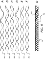
- FIGS. 8A-8F illustrate the components of 1 ⁇ 1 braiding arrangement that transitions to a 1 ⁇ 3 braiding arrangement ( FIG. 8G ) consistent with the disclosure
- FIGS. 9A-9F illustrate the components of 1 ⁇ 1 braiding arrangement that transitions to a 3 ⁇ 3 braiding arrangement ( FIG. 9G ) consistent with the disclosure
- FIGS. 10A-10D illustrate the components of 1 ⁇ 1 braiding arrangement that transitions to a 1 ⁇ 2 braiding arrangement ( FIG. 10E ) consistent with the disclosure
- FIGS. 11A-11D illustrate the components of 1 ⁇ 1 braiding arrangement that transitions to a 2 ⁇ 2 braiding arrangement ( FIG. 11E ) consistent with the disclosure
- FIGS. 12A-12D illustrate the components of 2 ⁇ 2 braiding arrangement that transitions to a 1 ⁇ 4 braiding arrangement ( FIG. 12E ) consistent with the disclosure
- FIG. 13 illustrates an expandable mesh created from wires of a cabled shaft consistent with the disclosure
- FIG. 14 illustrates a clot retrieval process consistent with the disclosure.
- FIG. 1 depicts a mesh structure associated with expandable mesh structure 100 .
- the mesh structure depicted in FIG. 1 includes with varying wire arrangements, which can create interstices of different sizes when the expandable mesh structure 100 is in an expanded state.
- interstices 110 in expandable mesh structure 100 can be larger than interstices 105 in expandable mesh structure 100 when expandable member 100 is in an expanded state.
- the wires of the expandable mesh structure 100 can be used to create a cable shaft, such as cable shaft 90 .
- the interstices in a first expandable section may differ in size from the interstices in a second expandable section by a predetermined amount.
- the interstices in the second expandable section may be approximately three times, five times, ten times, or twenty times larger than the interstices in the first expandable section.
- this invention is not limited to a device with only two wire arrangements; alternating wire arrangements can also be used to create a structure with varying sized openings.
- one embodiment of the device can be made of alternating braided wires and a segment of straight or non-braided wires ( FIG. 2 ).
- the braided portion between the straight wire segments may be a stable piece that holds the wire arrangements together.
- it may create a border between the large openings.
- FIG. 2 depicts expandable mesh structure 200 with alternative mesh arrangements.
- region 215 of expandable mesh structure 200 can include braided wires and region 220 of expandable mesh structure 200 can include straight (or aligned, parallel) wires.
- FIG. 3 is an illustration of an expandable mesh structure 300 in which each couple of wires is intertwined between the braided sections and, as a result, the large openings are created.
- the distal braided section also serves as a filter in case particles break off and flow distally during the retrieval process.
- expandable mesh structure 300 is shown with a braided region 324 that transitions to an intertwined region 331 (with intertwined wire couples), and then is shown as transitioning (or alternating) back to a braided region 326 .
- the interstices 325 can be smaller than the interstices 330 when expandable mesh structure 300 is in an expanded state.
- FIG. 4 depicts a close-up view of expandable mesh structure 400 (when in an expanded state).
- interstices 440 associated with a region of intertwined wires
- interstices 435 associated with a braided arrangement
- braiding patterns can be utilized to create the different interstices.
- 1 ⁇ 1 one wire over one wire
- 3 ⁇ 1 3 wires over 1 wire
- Other braiding examples are, but are not limited to, 2 ⁇ 2 (two wires over two wires) combined with three intertwined wires, or 2 ⁇ 2 combined with 4 ⁇ 1 or 1 ⁇ 1 combined with 3 ⁇ 3 ( FIG. 6 ).
- FIG. 5 depicts an expandable mesh structure 500 which includes a 1 ⁇ 1 braiding arrangement (in region 545 ) that transitions to a 1 ⁇ 3 braiding arrangement (in region 550 ).
- the interstices in region 550 can be larger than the interstices in region 545 .
- FIG. 6 depicts an expandable mesh structure 600 which includes a 1 ⁇ 1 braiding arrangement throughout; however the interstices in region 660 can be larger than the interstices in region 655 when expandable mesh structure 600 is in an expanded state.
- FIG. 7 depicts pairs of continuous braided wires (pair 701 in FIG. 7A , pair 711 in FIG. 7B , pair 721 in FIG. 7C , pair 731 in FIG. 7D , pair 741 in FIG. 7E , and pair 751 in FIG. 7F ) that, together, make up the braid with uniform interstices 765 depicted in expandable mesh structure 700 ( FIG. 7G ).
- the expandable mesh structure 700 includes a hollow region (shown as cylindrical in FIG. 7 ).
- the dashed lines in FIG. 7 (and in FIGS. 8-12 ) correspond to that portion of a continuous wire that falls “behind” the hollow portion (when viewed from the “front” as shown in FIG. 7 ).
- FIG. 8 depicts pairs of continuous braided wires (pair 802 in FIG. 8A , pair 812 in FIG. 8B , pair 822 in FIG. 8C , pair 832 in FIG. 8D , pair 842 in FIG. 8E , and pair 852 in FIG. 8F ) that, together, make up the 1 ⁇ 1 braiding arrangement that transitions to a 1 ⁇ 3 braiding arrangement depicted in the expandable mesh structure 800 of FIG. 8G .
- interstices 870 can be larger than interstices 765 when expandable mesh structure 800 is in an expanded state.
- FIG. 9 depicts pairs of continuous braided wires (pair 901 in FIG. 9A , pair 913 in FIG. 9B , pair 923 in FIG. 9C , pair 933 in FIG. 9D , pair 943 in FIG. 9E , and pair 953 in FIG. 9F ) that, together, make up the 1 ⁇ 1 braiding arrangement that transitions to a 3 ⁇ 3 braiding arrangement depicted in the expandable mesh structure 900 of FIG. 9G .
- interstices 980 can be larger than interstices 765 when expandable mesh structure 900 is in an expanded state.
- FIG. 10 depicts pairs of continuous braided wires (pair 1004 in FIG. 10A , pair 1014 in FIG. 10B , pair 1024 in FIG. 10C , and pair 1034 in FIG. 10D ) that, together, make up the 1 ⁇ 1 braiding arrangement that transitions to a 1 ⁇ 2 braiding arrangement depicted in the expandable mesh structure 1000 of FIG. 10E .
- interstices 1090 can be larger than interstices 1085 when expandable mesh structure 1000 is in an expanded state.
- FIG. 11 depicts pairs of continuous braided wires (pair 1106 in FIG. 11A , pair 1116 in FIG. 11B , pair 1126 in FIG. 11C , and pair 1136 in FIG. 11D ) that, together, make up the 1 ⁇ 1 braiding arrangement that transitions to a 2 ⁇ 2 braiding arrangement depicted in the expandable mesh structure 1100 of FIG. 11E .
- interstices 1191 can be larger than interstices 1085 when expandable mesh structure 1100 is in an expanded state.
- FIG. 12 depicts pairs of continuous braided wires (pair 1207 in FIG. 12A , pair 1217 in FIG. 12B , pair 1227 in FIG. 12C , and pair 1237 in FIG. 12D ) that, together, make up the 2 ⁇ 2 braiding arrangement that transitions to a 1 ⁇ 4 braiding arrangement depicted in the expandable mesh structure 1200 of FIG. 12E .
- interstices 1191 can be larger than interstices 1292 when expandable mesh structure 1200 is in an expanded state.
- the larger interstices can be created by keeping the same general wire arrangements (for instance one over one) but by changing the angle of the intersection.
- the large interstices can be achieved by reducing the number of wires at some portion of the arrangement (for instance, by terminating a number of the wires at the end of the first section).
- each of the expandable sections may be configured to expand to different outer diameters.
- a first expandable section may be configured to expand to an outer diameter smaller than the outer diameter of the second expandable section when the second expandable section is expanded. That is, when each of the sections of the device is expanded, the device may have multiple, different outer diameters along the length of the device.
- the expandable sections having different expanded outer diameters may be arranged in any desired order with respect to one another along the length of the device.
- a first type of expandable section may be located between a plurality of expandable sections of a second type.
- This arrangement may result in an expandable structure with at least two peaks and one valley.
- other arrangements may result in an expandable structure with other quantities of peaks and valleys formed as a result of the different diameters of the expandable sections.
- the single wires can differ from each other in their characteristics; material, diameter, shape, cross-sectional shape, radio-opacity, etc.
- one Platinum wire can be used to make the structure visible under fluoroscopy while the other wires can be of less visible materials, such as Nitinol.
- polymer wires can be combined with metal wires to achieve the required mechanical properties of the structure.
- flat wire might be used to lower the overall profile of the device or round wires can be used for better kink resistance. Nonetheless, the disclosure above can incorporate any types of wires from any materials, sizes and shapes.
- the wires might be coated or covered. A coating might be desirable to ease the delivery of the structure through a tight micro-catheter.
- the wires might be drug coated to affect a treatment or to increase adherence to the clot.
- the section of the small interstices might be covered with an outer polymer or other covering to allow even greater protection against distal shower.
- the expandable mesh may also be extended from an elongate shaft.
- the shaft may be long enough to deliver and control the mesh from outside the body.
- the shaft might be made of a stiff portion to enhance pushability and stability on its proximal part, and a flexible portion on its distal part.
- the distal part may be connected at its distal end to the expandable mesh.
- the proximal stiffer part can be produced from a hollow metallic tube or from a reinforced polymer structure.
- the distal and/or proximal part might be also created from a reinforced polymer structure of a more flexible nature. In addition, it might be created from a cut metallic tube. Moreover, it may be created like a cable, for example, from strands of wires arranged in a coiled assembly.
- FIG. 13 illustrates expandable mesh 1300 created from wires of a cabled shaft (such as shaft 90 ).
- pull or control wires that can be connected to the expandable members. These wires may extend through the flexible portion of the shaft to the proximal portion of the shaft and, when a force is exerted on the pull or control wire (e.g., a pull force), the mesh member may expand.
- a force is exerted on the pull or control wire (e.g., a pull force)
- the mesh member may expand.
- only one core wire may be used and connected to the expandable member at its distal end.
- the wires of the expandable member might terminate in a coiled structure.
- the pull wire may be connected to the coiled structure at the distal part of the expandable member. When the pull wire is pulled, it may expand all of the wires of the expandable member and thereby expanding the expandable member.
- the wires of the expandable member can terminate in other fashions. For example, they can be arranged in parallel at the distal end.
- one or more of the wires can be curved back and used as pull wires themselves
- the pull wire alternative may have some advantages over the self-expanding one.
- the amount of expansion might be controlled by use (the more pulled, the more expansion at the distal end) unlike the self-expanding option which may be pre-set. This can be beneficial if, for example, the clot is retrieved through blood vessels of varying diameter.
- the device since the device may be delivered in an unexpanded state, delivery through a tight micro-catheter might be easier.
- Yet an additional alternative for expansion of the expandable member is to use temperature changes or to utilize currents that will cause metallic wires to change their mechanical properties.
- the device disclosed may be used to remove an obstruction from a vessel.
- This obstruction may be a blood clot of different origins but is not limited to such.
- the obstruction can also be plaque of foreign bodies.
- the device may be sized for use in a conduit other than a blood vessel.
- One embodiment of a method for removing an obstruction from a vessel with the disclosed device may include inserting the device having the expandable structure into the vessel.
- the expandable section may include at least one end region having interstices that are at least three times smaller in size than interstices in a central region.
- the expandable structure may then be positioned in a desired location. For example, the expandable structure may be moved so that at least the central region that coincides with the obstruction (e.g., is aligned with, alongside, fully within, or partially within the obstruction). Once aligned, the expandable structure may be expanded, for example, by using the pull or control wire, to embed some or all of the obstruction in the central region.
- the expandable structure containing the embedded obstruction may then be withdrawn from the vessel.
- FIG. 14 One implementation of the embodiment of the method for removing the obstruction from the vessel is illustrated in FIG. 14 .
- the device may be used to remove a variety of other types of obstructions as well.
- the method of use for the device may include one or more of the following:
- the expandable member can also be used to retrieve additional foreign materials from the bodily lumens.
- it can also be used to retrieve pulmonary embolism, kidney stones, etc.
- the device may include a flexible shaft made of 12 wires.
- 6 of the wires may be arranged in a clockwise direction, and the other 6 may be arranged in a counterclockwise direction.
- the non-braided section of the expandable member may include intertwined pairs.
- the wires substantially do not cross in the non-braided section of the expandable member.
- different types of braiding may be employed in same expandable member.
- An intraluminal device includes any expandable member that may be inserted into a lumen, conduit, or vessel.
- a wire mesh structure includes any structure made at least wholly or partially from wire, regardless of whether the structure is made from metal, polymers, or any other material.
- a wire arrangement pattern is a configuration of wires. In its broadest sense, the pattern does not have to have any measure of regularity. In some embodiments, the configuration may include repetition, in others there may be no repetition.
- Interstices include any intervening space, including, for example, any form of gap, space, hole, interval, or slit.
- a braid is a configuration of a plurality of strands with diagonal overlaying or overlap, such as in a weave or interlacing.
Priority Applications (1)
| Application Number | Priority Date | Filing Date | Title |
|---|---|---|---|
| US15/548,973 US11083473B2 (en) | 2015-02-06 | 2016-02-05 | Systems and methods for intravascular obstruction removal |
Applications Claiming Priority (3)
| Application Number | Priority Date | Filing Date | Title |
|---|---|---|---|
| US201562112862P | 2015-02-06 | 2015-02-06 | |
| US15/548,973 US11083473B2 (en) | 2015-02-06 | 2016-02-05 | Systems and methods for intravascular obstruction removal |
| PCT/IB2016/000200 WO2016125018A2 (en) | 2015-02-06 | 2016-02-05 | Systems and methods for intravascular obstruction removal |
Related Parent Applications (1)
| Application Number | Title | Priority Date | Filing Date |
|---|---|---|---|
| PCT/IB2016/000200 A-371-Of-International WO2016125018A2 (en) | 2015-02-06 | 2016-02-05 | Systems and methods for intravascular obstruction removal |
Related Child Applications (1)
| Application Number | Title | Priority Date | Filing Date |
|---|---|---|---|
| US17/367,113 Continuation US11925368B2 (en) | 2015-02-06 | 2021-07-02 | Systems and methods for intravascular obstruction removal |
Publications (2)
| Publication Number | Publication Date |
|---|---|
| US20180028209A1 US20180028209A1 (en) | 2018-02-01 |
| US11083473B2 true US11083473B2 (en) | 2021-08-10 |
Family
ID=56564832
Family Applications (2)
| Application Number | Title | Priority Date | Filing Date |
|---|---|---|---|
| US15/548,973 Active 2036-08-26 US11083473B2 (en) | 2015-02-06 | 2016-02-05 | Systems and methods for intravascular obstruction removal |
| US17/367,113 Active 2036-07-16 US11925368B2 (en) | 2015-02-06 | 2021-07-02 | Systems and methods for intravascular obstruction removal |
Family Applications After (1)
| Application Number | Title | Priority Date | Filing Date |
|---|---|---|---|
| US17/367,113 Active 2036-07-16 US11925368B2 (en) | 2015-02-06 | 2021-07-02 | Systems and methods for intravascular obstruction removal |
Country Status (10)
| Country | Link |
|---|---|
| US (2) | US11083473B2 (he) |
| EP (1) | EP3253306B1 (he) |
| JP (1) | JP2018504238A (he) |
| KR (1) | KR20170115574A (he) |
| CN (1) | CN107205745A (he) |
| AU (1) | AU2016214072A1 (he) |
| ES (1) | ES2949690T3 (he) |
| HK (1) | HK1247798A1 (he) |
| IL (1) | IL253851B2 (he) |
| WO (1) | WO2016125018A2 (he) |
Families Citing this family (30)
| Publication number | Priority date | Publication date | Assignee | Title |
|---|---|---|---|---|
| US9265512B2 (en) | 2013-12-23 | 2016-02-23 | Silk Road Medical, Inc. | Transcarotid neurovascular catheter |
| ES2577288B8 (es) | 2015-01-13 | 2019-01-10 | Anaconda Biomed S L | Dispositivo para trombectomía |
| US11771446B2 (en) | 2020-10-19 | 2023-10-03 | Anaconda Biomed, S.L. | Thrombectomy system and method of use |
| US10426497B2 (en) | 2015-07-24 | 2019-10-01 | Route 92 Medical, Inc. | Anchoring delivery system and methods |
| ES2932764T3 (es) | 2015-02-04 | 2023-01-26 | Route 92 Medical Inc | Sistema de trombectomía por aspiración rápida |
| US11065019B1 (en) | 2015-02-04 | 2021-07-20 | Route 92 Medical, Inc. | Aspiration catheter systems and methods of use |
| DK3370641T3 (da) * | 2015-11-04 | 2020-11-23 | Rapid Medical Ltd | Intraluminal anordning |
| EP3419528B1 (en) | 2016-02-24 | 2023-06-07 | Incept, LLC | Enhanced flexibility neurovascular catheter |
| AU2017349575B2 (en) * | 2016-10-27 | 2022-11-17 | Rapid Medical Ltd. | Woven wire intraluminal device |
| WO2018109566A2 (en) | 2016-12-18 | 2018-06-21 | Rapid Medical Ltd. | Controllable retriever with distal clot anchor |
| JP7264581B2 (ja) | 2017-01-06 | 2023-04-25 | インセプト、リミテッド、ライアビリティ、カンパニー | 動脈瘤治療装置向けの抗血栓性コーティング |
| EP3568186B1 (en) | 2017-01-10 | 2022-09-14 | Route 92 Medical, Inc. | Aspiration catheter systems |
| US11490908B2 (en) | 2017-11-09 | 2022-11-08 | Contego Medical , Inc. | Thrombectomy device and methods of use |
| CN111904675B (zh) * | 2018-02-26 | 2023-04-25 | 上海加奇生物科技苏州有限公司 | 取栓支架及血栓抓捕器 |
| CN112203593A (zh) | 2018-05-01 | 2021-01-08 | 因赛普特有限责任公司 | 用于从血管内部位去除闭塞性物质的装置和方法 |
| US11395665B2 (en) | 2018-05-01 | 2022-07-26 | Incept, Llc | Devices and methods for removing obstructive material, from an intravascular site |
| JP2021523793A (ja) | 2018-05-17 | 2021-09-09 | ルート92メディカル・インコーポレイテッドRoute 92 Medical, Inc. | 吸引カテーテルシステム及び使用方法 |
| US10939931B2 (en) * | 2018-06-19 | 2021-03-09 | Stryker Corporation | Embolectomy device having multiple embolectomy structures |
| US11517335B2 (en) | 2018-07-06 | 2022-12-06 | Incept, Llc | Sealed neurovascular extendable catheter |
| US11471582B2 (en) | 2018-07-06 | 2022-10-18 | Incept, Llc | Vacuum transfer tool for extendable catheter |
| KR20210038910A (ko) * | 2018-07-26 | 2021-04-08 | 라피드 메디칼 리미티드 | 와이어 편조 구성을 구비한 관강내 장치 |
| US10390982B1 (en) | 2018-11-13 | 2019-08-27 | Icad Endovascular Llc | Systems and methods for delivery retrievable stents |
| WO2020144071A1 (en) | 2019-01-11 | 2020-07-16 | Anaconda Biomed, Sl | Loading device for loading a medical device into a catheter |
| US11766539B2 (en) | 2019-03-29 | 2023-09-26 | Incept, Llc | Enhanced flexibility neurovascular catheter |
| CN113347916A (zh) | 2019-10-15 | 2021-09-03 | 因普瑞缇夫护理公司 | 用于多变量卒中检测的系统和方法 |
| JP2023507553A (ja) | 2019-12-18 | 2023-02-24 | インパラティブ、ケア、インク. | 静脈血栓塞栓症を治療するための方法及びシステム |
| US11259821B2 (en) | 2019-12-18 | 2022-03-01 | Imperative Care, Inc. | Aspiration system with accelerated response |
| US11633272B2 (en) | 2019-12-18 | 2023-04-25 | Imperative Care, Inc. | Manually rotatable thrombus engagement tool |
| AU2021235887A1 (en) | 2020-03-10 | 2022-09-08 | Imperative Care, Inc. | Enhanced flexibility neurovascular catheter |
| US11207497B1 (en) | 2020-08-11 | 2021-12-28 | Imperative Care, Inc. | Catheter with enhanced tensile strength |
Citations (25)
| Publication number | Priority date | Publication date | Assignee | Title |
|---|---|---|---|---|
| US5348788A (en) | 1991-01-30 | 1994-09-20 | Interpore Orthopaedics, Inc. | Mesh sheet with microscopic projections and holes |
| JPH10151136A (ja) | 1996-07-25 | 1998-06-09 | Target Therapeutics Inc | 機械的血餅処置デバイス |
| US6409750B1 (en) | 1999-02-01 | 2002-06-25 | Board Of Regents, The University Of Texas System | Woven bifurcated and trifurcated stents and methods for making the same |
| JP2003513748A (ja) | 1999-11-16 | 2003-04-15 | ボストン サイエンティフィック リミテッド | 多部分フィラメント状管腔内ステント |
| US20060030933A1 (en) | 2004-08-04 | 2006-02-09 | Delegge Rebecca | Thermal transition methods and devices |
| US7004954B1 (en) | 2000-03-22 | 2006-02-28 | Endovascular Technologies, Inc. | Device for removal of thrombus through physiological adhesion |
| US20070106302A1 (en) | 2005-11-04 | 2007-05-10 | Ethicon Endo-Surgery, Inc | Lumen traversing device |
| US20070135834A1 (en) | 2003-01-30 | 2007-06-14 | Ev3 Inc. | Embolic filters with controlled pore size |
| US20070168019A1 (en) | 2006-01-13 | 2007-07-19 | Aga Medical Corporation | Intravascular deliverable stent for reinforcement of vascular abnormalities |
| US20070185500A1 (en) * | 2006-02-03 | 2007-08-09 | Martin Brian B | Devices for restoring blood flow within blocked vasculature |
| US20080262528A1 (en) * | 2007-04-17 | 2008-10-23 | Lazarus Effect, Inc. | Complex wire formed devices |
| US20090062841A1 (en) | 2004-03-19 | 2009-03-05 | Aga Medical Corporation | Device for occluding vascular defects |
| CN102077870A (zh) | 2009-11-28 | 2011-06-01 | 刘柏彤 | 枸杞牛奶的制备方法 |
| US20110213403A1 (en) * | 2010-02-23 | 2011-09-01 | Maria Aboytes | Devices and methods for vascular recanalization |
| US20110245841A1 (en) | 2010-04-01 | 2011-10-06 | Xenolith Medical Ltd. | Expandable devices and methods of use |
| US20120283510A1 (en) | 2009-12-31 | 2012-11-08 | Ams Research Corporation | Pelvic Implants having Perimeter Imaging Features |
| WO2013005195A1 (en) | 2011-07-07 | 2013-01-10 | Jayandiran Pillai | Aneurysm occluder |
| US20130158592A1 (en) * | 2011-12-16 | 2013-06-20 | Stryker Nv Operations Limited | Embolectomy cage |
| WO2013102848A2 (en) | 2012-01-04 | 2013-07-11 | Rapid Medical Ltd. | Devices and methods for assisting medical treatments |
| US20140046359A1 (en) | 2012-08-13 | 2014-02-13 | Microvention, Inc. | Shaped Removal Device |
| CN103764049A (zh) | 2011-07-26 | 2014-04-30 | 迈克尔·P·马克思 | 血管内血栓切除装置及其使用方法 |
| WO2014081077A1 (ko) | 2012-11-26 | 2014-05-30 | 연세대학교 원주산학협력단 | 혈전 제거용 스텐트 모듈 |
| US20140277098A1 (en) | 2013-03-15 | 2014-09-18 | Insera Therapeutics, Inc. | Methods of embolic filtering |
| CN104168845A (zh) | 2012-01-17 | 2014-11-26 | 珀弗娄医疗有限公司 | 用于移除堵塞物的方法和设备 |
| US20140371779A1 (en) * | 2013-03-14 | 2014-12-18 | Neuravi Limited | Clot retrieval device for removing occlusive clot from a blood vessel |
Family Cites Families (3)
| Publication number | Priority date | Publication date | Assignee | Title |
|---|---|---|---|---|
| US20050154400A1 (en) * | 2003-12-18 | 2005-07-14 | Asahi Intecc Co., Ltd | Medical treating tool |
| CN102078870A (zh) * | 2009-12-01 | 2011-06-01 | 梁嘉麟 | 清除管道阻塞物的手动与自动相结合的钳取装置及其使用方法 |
| WO2012162437A1 (en) * | 2011-05-23 | 2012-11-29 | Lazarus Effect, Inc. | Retrieval systems and methods for use thereof |
-
2016
- 2016-02-05 IL IL253851A patent/IL253851B2/he unknown
- 2016-02-05 ES ES16746182T patent/ES2949690T3/es active Active
- 2016-02-05 EP EP16746182.1A patent/EP3253306B1/en active Active
- 2016-02-05 CN CN201680008197.0A patent/CN107205745A/zh active Pending
- 2016-02-05 KR KR1020177024829A patent/KR20170115574A/ko unknown
- 2016-02-05 AU AU2016214072A patent/AU2016214072A1/en not_active Abandoned
- 2016-02-05 US US15/548,973 patent/US11083473B2/en active Active
- 2016-02-05 WO PCT/IB2016/000200 patent/WO2016125018A2/en active Application Filing
- 2016-02-05 JP JP2017541338A patent/JP2018504238A/ja active Pending
-
2018
- 2018-06-01 HK HK18107224.3A patent/HK1247798A1/zh unknown
-
2021
- 2021-07-02 US US17/367,113 patent/US11925368B2/en active Active
Patent Citations (28)
| Publication number | Priority date | Publication date | Assignee | Title |
|---|---|---|---|---|
| US5348788A (en) | 1991-01-30 | 1994-09-20 | Interpore Orthopaedics, Inc. | Mesh sheet with microscopic projections and holes |
| JPH10151136A (ja) | 1996-07-25 | 1998-06-09 | Target Therapeutics Inc | 機械的血餅処置デバイス |
| US6409750B1 (en) | 1999-02-01 | 2002-06-25 | Board Of Regents, The University Of Texas System | Woven bifurcated and trifurcated stents and methods for making the same |
| US20070106370A1 (en) * | 1999-11-16 | 2007-05-10 | Boston Scientific Scimed, Inc. | Multi-section filamentary endoluminal stent |
| JP2003513748A (ja) | 1999-11-16 | 2003-04-15 | ボストン サイエンティフィック リミテッド | 多部分フィラメント状管腔内ステント |
| US7004954B1 (en) | 2000-03-22 | 2006-02-28 | Endovascular Technologies, Inc. | Device for removal of thrombus through physiological adhesion |
| US20070135834A1 (en) | 2003-01-30 | 2007-06-14 | Ev3 Inc. | Embolic filters with controlled pore size |
| US20090062841A1 (en) | 2004-03-19 | 2009-03-05 | Aga Medical Corporation | Device for occluding vascular defects |
| US20060030933A1 (en) | 2004-08-04 | 2006-02-09 | Delegge Rebecca | Thermal transition methods and devices |
| US20070106302A1 (en) | 2005-11-04 | 2007-05-10 | Ethicon Endo-Surgery, Inc | Lumen traversing device |
| US20070168019A1 (en) | 2006-01-13 | 2007-07-19 | Aga Medical Corporation | Intravascular deliverable stent for reinforcement of vascular abnormalities |
| US20070185500A1 (en) * | 2006-02-03 | 2007-08-09 | Martin Brian B | Devices for restoring blood flow within blocked vasculature |
| US20080262528A1 (en) * | 2007-04-17 | 2008-10-23 | Lazarus Effect, Inc. | Complex wire formed devices |
| CN102077870A (zh) | 2009-11-28 | 2011-06-01 | 刘柏彤 | 枸杞牛奶的制备方法 |
| US20120283510A1 (en) | 2009-12-31 | 2012-11-08 | Ams Research Corporation | Pelvic Implants having Perimeter Imaging Features |
| US20110213403A1 (en) * | 2010-02-23 | 2011-09-01 | Maria Aboytes | Devices and methods for vascular recanalization |
| WO2011106426A1 (en) | 2010-02-23 | 2011-09-01 | Maria Aboytes | Devices and methods for vascular recanalization |
| US20150223829A1 (en) * | 2010-02-23 | 2015-08-13 | Medina Medical, Inc. | Devices and Methods for Vascular Recanalization |
| US20110245841A1 (en) | 2010-04-01 | 2011-10-06 | Xenolith Medical Ltd. | Expandable devices and methods of use |
| WO2013005195A1 (en) | 2011-07-07 | 2013-01-10 | Jayandiran Pillai | Aneurysm occluder |
| CN103764049A (zh) | 2011-07-26 | 2014-04-30 | 迈克尔·P·马克思 | 血管内血栓切除装置及其使用方法 |
| US20130158592A1 (en) * | 2011-12-16 | 2013-06-20 | Stryker Nv Operations Limited | Embolectomy cage |
| WO2013102848A2 (en) | 2012-01-04 | 2013-07-11 | Rapid Medical Ltd. | Devices and methods for assisting medical treatments |
| CN104168845A (zh) | 2012-01-17 | 2014-11-26 | 珀弗娄医疗有限公司 | 用于移除堵塞物的方法和设备 |
| US20140046359A1 (en) | 2012-08-13 | 2014-02-13 | Microvention, Inc. | Shaped Removal Device |
| WO2014081077A1 (ko) | 2012-11-26 | 2014-05-30 | 연세대학교 원주산학협력단 | 혈전 제거용 스텐트 모듈 |
| US20140371779A1 (en) * | 2013-03-14 | 2014-12-18 | Neuravi Limited | Clot retrieval device for removing occlusive clot from a blood vessel |
| US20140277098A1 (en) | 2013-03-15 | 2014-09-18 | Insera Therapeutics, Inc. | Methods of embolic filtering |
Non-Patent Citations (6)
| Title |
|---|
| Examination Report No. 1 from IP Australia for counterpart Australian Application No. 2016214072, dated Sep. 16, 2019 (3 pages). |
| Extended European Search Report dated Nov. 9, 2018, issued by the European Patent Office in counterpart European Patent Application No. EP 16 74 6182.1. |
| First Notification of Office Action issued by the China National Intellectual Property Administration dated Nov. 27, 2019, in corresponding Chinese Application No. 201680008197.0. |
| International Search Report from the U.S. Patent & Trademark Office for International Application No. PCT/IB2016/000200, dated Aug. 5, 2016. |
| Office Action from the Japan Patent Office for counterpart Japanese Application No. 2017-541338, dated Nov. 26, 2019, with translation (13 pages). |
| Written Opinion of the International Searching Authority from the U.S. Patent & Trademark Office for International Application No. PCT/IB2016/000200, dated Aug. 5, 2016. |
Also Published As
| Publication number | Publication date |
|---|---|
| EP3253306B1 (en) | 2023-06-07 |
| US20180028209A1 (en) | 2018-02-01 |
| WO2016125018A3 (en) | 2016-10-13 |
| IL253851B1 (he) | 2023-06-01 |
| WO2016125018A2 (en) | 2016-08-11 |
| IL253851A0 (he) | 2017-09-28 |
| US20220183709A1 (en) | 2022-06-16 |
| EP3253306A2 (en) | 2017-12-13 |
| KR20170115574A (ko) | 2017-10-17 |
| JP2018504238A (ja) | 2018-02-15 |
| CN107205745A (zh) | 2017-09-26 |
| AU2016214072A1 (en) | 2017-07-27 |
| EP3253306A4 (en) | 2018-12-12 |
| IL253851B2 (he) | 2023-10-01 |
| ES2949690T3 (es) | 2023-10-02 |
| US11925368B2 (en) | 2024-03-12 |
| HK1247798A1 (zh) | 2018-10-05 |
Similar Documents
| Publication | Publication Date | Title |
|---|---|---|
| US20220183709A1 (en) | Systems and methods for intravascular obstruction removal | |
| JP7234190B2 (ja) | ステントおよびステント送達装置 | |
| EP3579765B1 (en) | Axial lengthening thrombus capture system | |
| US11382777B2 (en) | Stents having radiopaque mesh | |
| AU2009274431B2 (en) | Multi-layered medical device for treating a target site and associated method | |
| US20170259042A1 (en) | Axial lengthening thrombus capture system | |
| US5928260A (en) | Removable occlusion system for aneurysm neck | |
| WO2010051121A1 (en) | Multi-layer device with gap for treating a target site and associated method | |
| JP6712548B2 (ja) | インプラントの導入および解放システム | |
| US20210145466A1 (en) | Intraluminal device with variable wire configuration | |
| US20140276644A1 (en) | Elastic Catheter | |
| CN115175642A (zh) | 混合支架和支架取栓器 |
Legal Events
| Date | Code | Title | Description |
|---|---|---|---|
| AS | Assignment |
Owner name: RAPID MEDICAL LTD., ISRAEL Free format text: ASSIGNMENT OF ASSIGNORS INTEREST;ASSIGNORS:SUDIN, YURI;FRIEDMAN, AHARON;ECKHOUSE, RONEN;REEL/FRAME:043554/0137 Effective date: 20160303 |
|
| STPP | Information on status: patent application and granting procedure in general |
Free format text: DOCKETED NEW CASE - READY FOR EXAMINATION |
|
| AS | Assignment |
Owner name: RAPID MEDICAL LTD., ISRAEL Free format text: ASSIGNMENT OF ASSIGNORS INTEREST;ASSIGNORS:ECKHOUSE, RONEN;FRIEDMAN, AHARON;SUDIN, YURI;REEL/FRAME:048151/0826 Effective date: 20160303 |
|
| STPP | Information on status: patent application and granting procedure in general |
Free format text: NON FINAL ACTION MAILED |
|
| STPP | Information on status: patent application and granting procedure in general |
Free format text: RESPONSE TO NON-FINAL OFFICE ACTION ENTERED AND FORWARDED TO EXAMINER |
|
| STPP | Information on status: patent application and granting procedure in general |
Free format text: FINAL REJECTION MAILED |
|
| STPP | Information on status: patent application and granting procedure in general |
Free format text: DOCKETED NEW CASE - READY FOR EXAMINATION |
|
| STPP | Information on status: patent application and granting procedure in general |
Free format text: NON FINAL ACTION MAILED |
|
| STPP | Information on status: patent application and granting procedure in general |
Free format text: RESPONSE TO NON-FINAL OFFICE ACTION ENTERED AND FORWARDED TO EXAMINER |
|
| STPP | Information on status: patent application and granting procedure in general |
Free format text: RESPONSE AFTER FINAL ACTION FORWARDED TO EXAMINER |
|
| STPP | Information on status: patent application and granting procedure in general |
Free format text: NON FINAL ACTION MAILED |
|
| STPP | Information on status: patent application and granting procedure in general |
Free format text: RESPONSE TO NON-FINAL OFFICE ACTION ENTERED AND FORWARDED TO EXAMINER |
|
| STPP | Information on status: patent application and granting procedure in general |
Free format text: NOTICE OF ALLOWANCE MAILED -- APPLICATION RECEIVED IN OFFICE OF PUBLICATIONS |
|
| FEPP | Fee payment procedure |
Free format text: ENTITY STATUS SET TO SMALL (ORIGINAL EVENT CODE: SMAL); ENTITY STATUS OF PATENT OWNER: SMALL ENTITY |
|
| STPP | Information on status: patent application and granting procedure in general |
Free format text: PUBLICATIONS -- ISSUE FEE PAYMENT RECEIVED |
|
| STPP | Information on status: patent application and granting procedure in general |
Free format text: PUBLICATIONS -- ISSUE FEE PAYMENT VERIFIED |
|
| STCF | Information on status: patent grant |
Free format text: PATENTED CASE |