US11059737B2 - Method for manufacturing multicore optical fiber - Google Patents
Method for manufacturing multicore optical fiber Download PDFInfo
- Publication number
- US11059737B2 US11059737B2 US16/364,593 US201916364593A US11059737B2 US 11059737 B2 US11059737 B2 US 11059737B2 US 201916364593 A US201916364593 A US 201916364593A US 11059737 B2 US11059737 B2 US 11059737B2
- Authority
- US
- United States
- Prior art keywords
- optical fiber
- closed
- cladding material
- manufacturing
- multicore optical
- Prior art date
- Legal status (The legal status is an assumption and is not a legal conclusion. Google has not performed a legal analysis and makes no representation as to the accuracy of the status listed.)
- Active, expires
Links
Images


Classifications
-
- C—CHEMISTRY; METALLURGY
- C03—GLASS; MINERAL OR SLAG WOOL
- C03B—MANUFACTURE, SHAPING, OR SUPPLEMENTARY PROCESSES
- C03B37/00—Manufacture or treatment of flakes, fibres, or filaments from softened glass, minerals, or slags
- C03B37/01—Manufacture of glass fibres or filaments
- C03B37/012—Manufacture of preforms for drawing fibres or filaments
- C03B37/01205—Manufacture of preforms for drawing fibres or filaments starting from tubes, rods, fibres or filaments
- C03B37/01211—Manufacture of preforms for drawing fibres or filaments starting from tubes, rods, fibres or filaments by inserting one or more rods or tubes into a tube
- C03B37/01222—Manufacture of preforms for drawing fibres or filaments starting from tubes, rods, fibres or filaments by inserting one or more rods or tubes into a tube for making preforms of multiple core optical fibres
-
- C—CHEMISTRY; METALLURGY
- C03—GLASS; MINERAL OR SLAG WOOL
- C03B—MANUFACTURE, SHAPING, OR SUPPLEMENTARY PROCESSES
- C03B37/00—Manufacture or treatment of flakes, fibres, or filaments from softened glass, minerals, or slags
- C03B37/01—Manufacture of glass fibres or filaments
- C03B37/012—Manufacture of preforms for drawing fibres or filaments
- C03B37/01205—Manufacture of preforms for drawing fibres or filaments starting from tubes, rods, fibres or filaments
- C03B37/01225—Means for changing or stabilising the shape, e.g. diameter, of tubes or rods in general, e.g. collapsing
- C03B37/01228—Removal of preform material
- C03B37/01231—Removal of preform material to form a longitudinal hole, e.g. by drilling
-
- C—CHEMISTRY; METALLURGY
- C03—GLASS; MINERAL OR SLAG WOOL
- C03B—MANUFACTURE, SHAPING, OR SUPPLEMENTARY PROCESSES
- C03B37/00—Manufacture or treatment of flakes, fibres, or filaments from softened glass, minerals, or slags
- C03B37/01—Manufacture of glass fibres or filaments
- C03B37/012—Manufacture of preforms for drawing fibres or filaments
- C03B37/01205—Manufacture of preforms for drawing fibres or filaments starting from tubes, rods, fibres or filaments
- C03B37/01225—Means for changing or stabilising the shape, e.g. diameter, of tubes or rods in general, e.g. collapsing
- C03B37/01251—Reshaping the ends
-
- C—CHEMISTRY; METALLURGY
- C03—GLASS; MINERAL OR SLAG WOOL
- C03B—MANUFACTURE, SHAPING, OR SUPPLEMENTARY PROCESSES
- C03B37/00—Manufacture or treatment of flakes, fibres, or filaments from softened glass, minerals, or slags
- C03B37/01—Manufacture of glass fibres or filaments
- C03B37/012—Manufacture of preforms for drawing fibres or filaments
- C03B37/01205—Manufacture of preforms for drawing fibres or filaments starting from tubes, rods, fibres or filaments
- C03B37/01225—Means for changing or stabilising the shape, e.g. diameter, of tubes or rods in general, e.g. collapsing
- C03B37/01257—Heating devices therefor
-
- C—CHEMISTRY; METALLURGY
- C03—GLASS; MINERAL OR SLAG WOOL
- C03B—MANUFACTURE, SHAPING, OR SUPPLEMENTARY PROCESSES
- C03B37/00—Manufacture or treatment of flakes, fibres, or filaments from softened glass, minerals, or slags
- C03B37/01—Manufacture of glass fibres or filaments
- C03B37/012—Manufacture of preforms for drawing fibres or filaments
- C03B37/0128—Manufacture of preforms for drawing fibres or filaments starting from pulverulent glass
- C03B37/01282—Manufacture of preforms for drawing fibres or filaments starting from pulverulent glass by pressing or sintering, e.g. hot-pressing
-
- C—CHEMISTRY; METALLURGY
- C03—GLASS; MINERAL OR SLAG WOOL
- C03B—MANUFACTURE, SHAPING, OR SUPPLEMENTARY PROCESSES
- C03B37/00—Manufacture or treatment of flakes, fibres, or filaments from softened glass, minerals, or slags
- C03B37/01—Manufacture of glass fibres or filaments
- C03B37/02—Manufacture of glass fibres or filaments by drawing or extruding, e.g. direct drawing of molten glass from nozzles; Cooling fins therefor
- C03B37/025—Manufacture of glass fibres or filaments by drawing or extruding, e.g. direct drawing of molten glass from nozzles; Cooling fins therefor from reheated softened tubes, rods, fibres or filaments, e.g. drawing fibres from preforms
- C03B37/027—Fibres composed of different sorts of glass, e.g. glass optical fibres
-
- C—CHEMISTRY; METALLURGY
- C03—GLASS; MINERAL OR SLAG WOOL
- C03B—MANUFACTURE, SHAPING, OR SUPPLEMENTARY PROCESSES
- C03B37/00—Manufacture or treatment of flakes, fibres, or filaments from softened glass, minerals, or slags
- C03B37/01—Manufacture of glass fibres or filaments
- C03B37/02—Manufacture of glass fibres or filaments by drawing or extruding, e.g. direct drawing of molten glass from nozzles; Cooling fins therefor
- C03B37/025—Manufacture of glass fibres or filaments by drawing or extruding, e.g. direct drawing of molten glass from nozzles; Cooling fins therefor from reheated softened tubes, rods, fibres or filaments, e.g. drawing fibres from preforms
- C03B37/029—Furnaces therefor
-
- C—CHEMISTRY; METALLURGY
- C03—GLASS; MINERAL OR SLAG WOOL
- C03B—MANUFACTURE, SHAPING, OR SUPPLEMENTARY PROCESSES
- C03B2201/00—Type of glass produced
- C03B2201/06—Doped silica-based glasses
- C03B2201/08—Doped silica-based glasses doped with boron or fluorine or other refractive index decreasing dopant
- C03B2201/10—Doped silica-based glasses doped with boron or fluorine or other refractive index decreasing dopant doped with boron
-
- C—CHEMISTRY; METALLURGY
- C03—GLASS; MINERAL OR SLAG WOOL
- C03B—MANUFACTURE, SHAPING, OR SUPPLEMENTARY PROCESSES
- C03B2201/00—Type of glass produced
- C03B2201/06—Doped silica-based glasses
- C03B2201/08—Doped silica-based glasses doped with boron or fluorine or other refractive index decreasing dopant
- C03B2201/12—Doped silica-based glasses doped with boron or fluorine or other refractive index decreasing dopant doped with fluorine
-
- C—CHEMISTRY; METALLURGY
- C03—GLASS; MINERAL OR SLAG WOOL
- C03B—MANUFACTURE, SHAPING, OR SUPPLEMENTARY PROCESSES
- C03B2201/00—Type of glass produced
- C03B2201/06—Doped silica-based glasses
- C03B2201/08—Doped silica-based glasses doped with boron or fluorine or other refractive index decreasing dopant
- C03B2201/14—Doped silica-based glasses doped with boron or fluorine or other refractive index decreasing dopant doped with boron and fluorine
-
- C—CHEMISTRY; METALLURGY
- C03—GLASS; MINERAL OR SLAG WOOL
- C03B—MANUFACTURE, SHAPING, OR SUPPLEMENTARY PROCESSES
- C03B2203/00—Fibre product details, e.g. structure, shape
- C03B2203/40—Multifibres or fibre bundles, e.g. for making image fibres
-
- G—PHYSICS
- G02—OPTICS
- G02B—OPTICAL ELEMENTS, SYSTEMS OR APPARATUS
- G02B6/00—Light guides; Structural details of arrangements comprising light guides and other optical elements, e.g. couplings
- G02B6/02—Optical fibres with cladding with or without a coating
- G02B6/02042—Multicore optical fibres
-
- G—PHYSICS
- G02—OPTICS
- G02B—OPTICAL ELEMENTS, SYSTEMS OR APPARATUS
- G02B6/00—Light guides; Structural details of arrangements comprising light guides and other optical elements, e.g. couplings
- G02B6/02—Optical fibres with cladding with or without a coating
- G02B6/032—Optical fibres with cladding with or without a coating with non solid core or cladding
-
- G—PHYSICS
- G02—OPTICS
- G02B—OPTICAL ELEMENTS, SYSTEMS OR APPARATUS
- G02B6/00—Light guides; Structural details of arrangements comprising light guides and other optical elements, e.g. couplings
- G02B6/02—Optical fibres with cladding with or without a coating
- G02B6/036—Optical fibres with cladding with or without a coating core or cladding comprising multiple layers
- G02B6/03616—Optical fibres characterised both by the number of different refractive index layers around the central core segment, i.e. around the innermost high index core layer, and their relative refractive index difference
- G02B6/03622—Optical fibres characterised both by the number of different refractive index layers around the central core segment, i.e. around the innermost high index core layer, and their relative refractive index difference having 2 layers only
- G02B6/03627—Optical fibres characterised both by the number of different refractive index layers around the central core segment, i.e. around the innermost high index core layer, and their relative refractive index difference having 2 layers only arranged - +
Definitions
- the present invention relates to a method for manufacturing a multicore optical fiber.
- a rod-in drawing method is one of methods for manufacturing optical fibers.
- a rod-in drawing method manufactures an optical fiber by inserting a core rod into a hole of a cladding material arranged in a vertical direction, and drawing the core rod and the cladding material while heating and integrating the core rod and the cladding material in a drawing furnace (see Japanese Unexamined Patent Application Publication No. 58-217443).
- Japanese Unexamined Patent Application Publication No. 2016-175779 describes a rod-in drawing method that manufactures a multicore optical fiber by using a cladding tube that has a plurality of holes formed to extend in an axial direction and core rods that each are inserted into a corresponding one of the holes.
- Rod-in drawing methods have advantages as follows to increase the size of a preform of a multicore optical fiber. That is, since the plurality of holes are formed in the phase of a preform and the core rods inserted into the holes are drawn while being integrated in the drawing furnace, an integration process in the phase of the preform is not required. Moreover, since the integration and drawing are vertically performed (in a vertical direction), the preform can be easily increased in size as compared with processing with a horizontal lathe.
- FIG. 7 is an explanatory diagram illustrating a cladding material 600 for a multicore optical fiber in this method.
- the left side is a longitudinal sectional view and the right side is a front view.
- the cladding material 600 has through holes 640 extending in an axial direction of a glass rod 610 .
- FIG. 8 is a conceptual diagram illustrating a state where core rods 650 are inserted into the cladding material 600 .
- a sealing member 630 for sealing first ends of the through holes 640 is attached by welding or another attaching method.
- the present invention provides a method for manufacturing a multicore optical fiber including a rod-in drawing step without necessity of a sealing member.
- a method for manufacturing a multicore optical fiber including a step of forming a plurality of ring-shaped closed-end holes to extend from a first end toward a second end in an axial direction of a glass rod; a step of heating bottom parts of the plurality of ring-shaped closed-end holes and softening a plurality of center rods that each are surrounded by a corresponding one of the plurality of ring-shaped closed-end holes; a step of pulling out the plurality of center rods toward a side of the first end, forming a plurality of columnar closed-end holes from the plurality of ring-shaped closed-end holes, and treating the glass rod as a cladding material; a connecting step of connecting a supporting pipe to the first end of the cladding material; an inserting step of inserting core rods into the plurality of columnar closed-end holes in a one-to-one correspondence after the connecting step; and a drawing step of drawing the cladding material and the
- the step of softening the center rods may include arranging the bottom parts of the ring-shaped closed-end holes in a heater.
- the step of pulling out the center rods preferably pulls out the center rods in a state where the glass rod vertically stands while the first end faces downward.
- the manufacturing method may further include a step of removing residues remaining in the columnar closed-end holes after the step of pulling out the center rods.
- the manufacturing method may further include a step of washing inside of the columnar closed-end holes after the step of removing the residues remaining in the columnar closed-end holes.
- a cladding material having a plurality of columnar closed-end holes can be manufactured without welding a sealing member as an additional member; the workability, the cost of equipment, and so forth, caused by welding the sealing member are decreased; the entry of impurities into through holes and fall of the entirety of the sealing member are prevented from occurring; and multicore optical fibers with high quality can be stably manufactured.
- FIG. 1 is a conceptual diagram of a drawing step in a method for manufacturing a multicore optical fiber according to an embodiment of the present invention.
- FIGS. 2A and 2B are conceptual diagrams of a cladding material having a ring-shaped closed-end hole in the method for manufacturing a multicore optical fiber according to the embodiment of the present invention, the left side of FIG. 2A being a sectional view, the right side of FIG. 2A being a front view, FIG. 2B being a perspective sectional view.
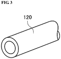
- FIG. 3 is a perspective view illustrating an example of a tool for forming a ring-shaped closed-end hole in FIGS. 2A and 2B .
- FIG. 4 is a conceptual diagram explaining a step of softening and pulling out a center rod in the method for manufacturing a multicore optical fiber according to the embodiment of the present invention.
- FIG. 5 is a conceptual diagram explaining a step of removing a residue of the center rod in the method for manufacturing a multicore optical fiber according to the embodiment of the present invention.
- FIG. 6 is a sectional view of a cladding material in the method for manufacturing a multicore optical fiber according to the embodiment of the present invention.
- FIG. 7 is an conceptual diagram illustrating a cladding material for a multicore optical fiber according to related art, the left side of FIG. 7 being a longitudinal sectional view, the right side of FIG. 7 being a front view.
- FIG. 8 is a conceptual diagram illustrating a state where core rods are inserted into the cladding material in FIG. 7 .
- the sealing member is used for sealing the first ends of the through holes of the cladding material.
- the sealing member is required to be tapered, in a step of heating a distal end portion of the preform, melting part of glass, and dropping the part of glass (dropping a droplet) at start of drawing, to reduce the size of the part of glass.
- the preform increases in size and the heat capacity required for welding the sealing member significantly increases, resulting in problems in view of the workability, the cost of equipment, and so forth.
- FIG. 1 is a conceptual diagram of a drawing step in a method for manufacturing a multicore optical fiber according to the embodiment of the present invention.
- a pressure controller 41 a holder 42 , and a drawing furnace 20 including a heater 21 are arranged at upper and lower positions in a vertical direction.
- the drawing apparatus 10 manufactures a multicore optical fiber (MCF) 50 by heating, softening, melting, and integrating a cladding material 100 and a core rod 30 , and drawing the integrated cladding material 100 and core rod 30 from a tapered part 105 .
- MCF multicore optical fiber
- the method for manufacturing a multicore optical fiber includes a cladding-material fabricating step, a connecting step, an inserting step, and a drawing step in that order.
- the cladding-material fabricating step the cladding material 100 is fabricated by forming a plurality of holes in a glass rod to extend in an axial direction as described later.
- a supporting pipe 40 is connected to a first end 101 (upper end in FIG. 1 ) of the cladding material 100 .
- the core rod 30 is inserted into each of a plurality of columnar closed-end holes 140 (closed-end holes each having a circular cross-section) of the cladding material 100 after the connecting step.
- the tapered part 105 at a second end (lower end in FIG. 1 ) of the cladding material 100 is heated by the drawing apparatus 10 , the cladding material 100 and the core rods 30 are softened, molten, integrated, and drawn, and thus the MCF 50 is manufactured.
- the supporting pipe 40 is held by the holder 42 , and the cladding material 100 that is connected to the supporting pipe 40 and the core rods 30 that each are inserted into a corresponding one of the plurality of columnar closed-end holes 140 of the cladding material 100 are perpendicularly arranged in the drawing furnace 20 .
- the pressure controller 41 located above the supporting pipe 40 adjusts the atmosphere and atmospheric pressure in the plurality of columnar closed-end holes 140 of the cladding material 100 , and the drawing furnace 20 heats lower end portions of the cladding material 100 and the core rods 30 .
- the cladding material 100 and the core rods 30 that constitute a preform of a multicore optical fiber are heated to a temperature equal to or higher than a working point, softened, molten, and integrated; and form a droplet.
- the formed droplet is spun (drawn) while the outside diameter of the droplet is controlled.
- the MCF 50 is manufactured.
- the MCF 50 drawn in the drawing furnace 20 then becomes a coated optical fiber through a coating die that applies resin and an ultraviolet (UV) furnace that hardens the resin, and is wounded by a winding bobbin. More specifically, a primary resin is applied, and the primary resin is hardened. Furthermore, a secondary resin is applied, and the secondary resin is hardened through, for example, irradiation with ultraviolet light.
- coating with resin layers of two layers is provided. Since the coating with resin layers of two layers or two or more layers is provided, the primary resin layer that is in contact with a bare optical fiber can inhibit an external force from being directly transmitted to the optical fiber, and furthermore, the secondary resin layer can prevent external damage.
- dies for applying the resin layers may be arranged in line in the spinning step, or the resin layers may be applied by a die that simultaneously applies two layers.
- the dies are not limited thereto. In the latter case, the height of the drawing tower can be decreased, and hence the construction cost of the drawing facility can be decreased.
- the secondary resin layer of the two resin layers thus formed preferably has a certain thickness to maintain the resistance to external damage. In general, the thickness is preferably 20 ⁇ m or more.
- the MCF 50 to be manufactured preferably complies with International Telecommunication Union, Telecommunication Standardization Sector (ITU-T) international standard G.652.D. Moreover, the MCF 50 preferably has bending loss characteristics that comply with G.657.A1, G.657.A2, and G.657.B3. Thus, the MCF 50 can be connected to a general-purpose single-mode optical fiber complying with G.652.D with a low loss, and can be treated similarly to an optical fiber of G.652.D in a transmission system.
- ITU-T International Telecommunication Union, Telecommunication Standardization Sector
- Cores and a cladding that collectively coats the cores of the MCF 50 can employ a refractive-index structure that is conceivable by those skilled in the art, for example, step index (SI) type, graded index (GI) type, W-type, or trench-type, to obtain appropriate values for transmission characteristics including crosstalk between cores and confinement loss.
- SI step index
- GI graded index
- W-type W-type
- trench-type trench-type
- the cores of the MCF 50 may have the same propagation constant or different propagation constants.
- the MCF 50 may be an uncoupled core MCF in which each core serves as an individual channel or a coupled core MCF in which a plurality of cores serve as a super channel across the plurality of cores.
- the cores of the MCF 50 each are made of a glass containing silicon dioxide (SiO 2 ) as a main component.
- the cladding material 100 may be made of a SiO 2 glass, and may contain at least one of fluorine (F) and chlorine (Cl), or may not contain fluorine or chlorine.
- the core rod 30 can be manufactured by using a vapor-phase glass synthesis method, such as vapor-phase axial deposition (VAD), outside vapor deposition (OVD), modified chemical vapor deposition (MCVD), or a plasma-activated chemical vapor deposition (PCVD). Furthermore, the core rod 30 may be provided with an intermediate optical cladding layer by a method of VAD, OVD, MCVD, a rod-in-collapse method, or a method similar thereto.
- VAD vapor-phase axial deposition
- OCVD modified chemical vapor deposition
- PCVD plasma-activated chemical vapor deposition
- drawing may be performed through a device that controls the cooling speed of glass to control the surface temperature of a bare optical fiber to a desirable temperature when the optical fiber enters the dies.
- a smaller Reynolds number of gas flowing through the device that controls the cooling speed is more desirable because vibration that is due to occurrence of a turbulent flow and is applied to a spun optical fiber decreases.
- the UV furnace may employ a magnetron or an ultraviolet light-emitting diode (LED).
- the light source of the UV LED does not generate heat, and hence the UV LED can be additionally provided with a mechanism that supplies hot air to raise the temperature in the furnace to an appropriate temperature.
- a component desorbed from the resin may stick to the inner surface of the furnace tube of the UV furnace and the power of the UV light that reaches the coating may change during drawing. Due to this, the degree of decrease in the power of the UV light during drawing may be monitored in advance, and the drawing duration may be set such that the power of the UV light to be radiated on the coating is substantially kept constant.
- the UV light leaking out from the furnace tube may be monitored, and the power of the UV light radiated on the coating may be controlled to be constant. This provides uniform fracture strength of an optical fiber over the entire length of the optical fiber.
- Manufacturing a cladding material having a plurality of columnar closed-end holes extending in an axial direction of a glass rod includes (1) a step of forming a ring-shaped closed-end hole from a first end toward a second end in the axial direction of the glass rod, (2) a step of heating a bottom part of the ring-shaped closed-end hole and softening a center rod surrounded by the ring-shaped closed-end hole, and (3) a step of pulling out the center rod toward a side of the first end and forming a columnar closed-end hole.
- FIGS. 2A, 2B, 4, 5, and 6 that are referenced in the following description illustrate a cladding material 100 in a lateral direction. However, the direction is not limited thereto.
- the first end having an opening of the columnar closed-end hole is desirably arranged at a lower side in a vertical direction.
- FIGS. 2A and 2B are conceptual diagrams of a cladding material 100 having a ring-shaped closed-end hole in the method for manufacturing a multicore optical fiber according to the embodiment of the present invention, the left side of FIG. 2A being a sectional view, the right side of FIG. 2A being a front view, FIG. 2B being a perspective view when a portion of the cladding material 100 is cut along lines X and Z of FIG. 2A and is viewed from below in FIG. 2A .
- a ring-shaped closed-end hole (a closed-end hole having a ring-shaped cross-section) 110 is formed to extend from a first end 101 toward a second end 102 in an axial direction of a glass rod serving as the cladding material 100 used in the drawing apparatus 10 .
- the ring-shaped closed-end hole 110 has a bottom part 103 with a predetermined thickness remaining with respect to the second end 102 .
- a plurality of the ring-shaped closed-end holes 110 are formed.
- a center rod 112 is formed in a state surrounded by a ring being a space.
- FIG. 3 is a perspective view illustrating an example of a tool for forming a ring-shaped closed-end hole.
- a pipe-shaped cutting tool 120 having diamond or the like at its distal end is typically used.
- the boring method is not limited thereto.
- the center rod 112 is arranged in a state surrounded by the ring-shaped closed-end hole 110 extending from the first end 101 .
- a plurality of the ring-shaped closed-end holes 110 are formed. While four ring-shaped closed-end holes 110 are illustrated in FIG. 2B as an example, the number of holes and the positions of holes can be appropriately set in accordance with the state of drawing, the size of the cladding material, and so forth.
- FIG. 4 is a conceptual diagram explaining a step of softening and pulling out a center rod in the method for manufacturing a multicore optical fiber according to the embodiment of the present invention.
- a heater 130 is arranged around the periphery of the bottom part 103 of the ring-shaped closed-end hole 110 of the cladding material 100 , and the heater 130 heats the periphery of the bottom part 103 .
- the heater 130 may employ an electric furnace, such as a resistance furnace, an arc furnace, or an induction furnace; or a fuel furnace. However, the furnace is not limited thereto.
- the bottom part 103 of the center rod 112 in each of the plurality of ring-shaped closed-end holes 110 can be substantially uniformly softened and partly molten.
- the center rod 112 After the bottom part 103 of the center rod 112 is substantially uniformly softened and partly molten, when the center rod 112 is pulled toward a side of the first end 101 (arrow direction) as illustrated in a lower section of FIG. 4 , the center rod 112 is extended near the bottom part 103 and then is cut. After the center rod 112 is cut, a columnar closed-end hole 140 is formed in a state where a remnant 104 after cutting partly remains at the bottom part 103 as illustrated in an upper section of FIG. 4 . With the configuration for heating with the heater 130 , the center rod 112 can be easily pulled out, and the columnar closed-end hole 140 can be easily formed. Note that, by pulling out the center rod in the vertical direction, a residue after the center rod is pulled out less likely remains in the columnar closed-end hole.
- the tapered remnant 104 facing toward the first end 101 remains in the bottom part 103 of the columnar closed-end hole 140 . If such a residue remains, a residue piece may be generated when a core rod is inserted into the columnar closed-end hole, and the residue piece may be mixed into the interface between the columnar closed-end hole and the core rod. This is not preferable. If the residue piece is mixed, the optical characteristics and mechanical characteristics of the drawn multicore optical fiber may be degraded.
- FIG. 5 is a conceptual diagram explaining a step of removing the residue of the center rod in the method for manufacturing a multicore optical fiber according to the embodiment of the present invention.
- a honing tool 160 such as a solid pointing tool may be inserted into the columnar closed-end hole 140 to mechanically remove the residue.
- the removing method is not limited to such a mechanically removing method.
- the residue may be irradiated with carbon dioxide laser beams, molten or vaporized, and removed.
- melting may be carried out such that the opening of the columnar closed-end hole faces downward in the vertical direction to suppress sticking of the residue to a wall surface of the columnar closed-end hole.
- the columnar closed-end hole 140 is in a state as illustrated in an upper section of FIG. 5 . Then, in the columnar closed-end hole 140 , it is preferable to further perform a washing step using a hydrogen fluoride aqueous solution or the like. In the columnar closed-end hole 140 , a grinding fluid, residues of grinding, and multiple pieces of glass may remain. If the columnar closed-end hole 140 is used as a jacket of the MCF 50 in this state, the optical characteristics and mechanical characteristics of the multicore optical fiber are degraded. With this configuration, since the step of washing the columnar closed-end hole is further included, the inside of the columnar closed-end hole can be cleaned.
- the washing fluid may employ the hydrogen fluoride aqueous solution; however, the washing fluid is not limited thereto. Since the step of removing a residue remaining in the columnar closed-end hole is further included, a multicore optical fiber with further high quality can be stably manufactured.
- FIG. 6 is a sectional view of the cladding material used in the method for manufacturing a multicore optical fiber according to the embodiment of the present invention.
- a portion near the second end 102 is tapered and hence a tapered part 105 is formed for drawing.
- the first end 101 having the opening of the columnar closed-end hole 140 is desirably arranged at the lower side in the vertical direction.
- 10 drawing apparatus 20 drawing furnace, 21 heater, 30 core rod, 40 supporting pipe, 41 pressure controller, 50 multicore optical fiber, 100 cladding material, 101 first end, 102 second end, 103 bottom part, 104 remnant, 105 tapered part, 110 ring-shaped closed-end hole, 112 center rod, 120 cutting tool, 130 heater, 140 columnar closed-end hole, 160 honing tool, 600 cladding material, 610 glass rod, 630 sealing member, 640 through hole, 650 core rod
Landscapes
- Engineering & Computer Science (AREA)
- Chemical & Material Sciences (AREA)
- Life Sciences & Earth Sciences (AREA)
- General Life Sciences & Earth Sciences (AREA)
- Geochemistry & Mineralogy (AREA)
- Manufacturing & Machinery (AREA)
- Materials Engineering (AREA)
- Organic Chemistry (AREA)
- Manufacture, Treatment Of Glass Fibers (AREA)
- Optical Fibers, Optical Fiber Cores, And Optical Fiber Bundles (AREA)
Applications Claiming Priority (3)
| Application Number | Priority Date | Filing Date | Title |
|---|---|---|---|
| JP2018-059819 | 2018-03-27 | ||
| JP2018059819A JP7024546B2 (ja) | 2018-03-27 | 2018-03-27 | マルチコア光ファイバの製造方法 |
| JPJP2018-059819 | 2018-03-27 |
Publications (2)
| Publication Number | Publication Date |
|---|---|
| US20190300421A1 US20190300421A1 (en) | 2019-10-03 |
| US11059737B2 true US11059737B2 (en) | 2021-07-13 |
Family
ID=68057694
Family Applications (1)
| Application Number | Title | Priority Date | Filing Date |
|---|---|---|---|
| US16/364,593 Active 2040-02-25 US11059737B2 (en) | 2018-03-27 | 2019-03-26 | Method for manufacturing multicore optical fiber |
Country Status (3)
| Country | Link |
|---|---|
| US (1) | US11059737B2 (ja) |
| JP (1) | JP7024546B2 (ja) |
| CN (1) | CN110304823B (ja) |
Families Citing this family (1)
| Publication number | Priority date | Publication date | Assignee | Title |
|---|---|---|---|---|
| US20230382779A1 (en) | 2021-02-22 | 2023-11-30 | Fujikura Ltd. | Multi-core optical fiber preform, multi-core optical fiber preform production method, and multi-core optical fiber production method |
Citations (4)
| Publication number | Priority date | Publication date | Assignee | Title |
|---|---|---|---|---|
| JPS58217443A (ja) | 1982-06-11 | 1983-12-17 | Nippon Telegr & Teleph Corp <Ntt> | 光フアイバの製造方法 |
| JP2016175779A (ja) | 2015-03-18 | 2016-10-06 | 住友電気工業株式会社 | 光ファイバ製造方法 |
| US20180244557A1 (en) * | 2017-02-28 | 2018-08-30 | Sumitomo Electric Industries, Ltd. | Production method for multicore optical fiber |
| US20180244556A1 (en) | 2017-02-28 | 2018-08-30 | Sumitomo Electric Industries, Ltd. | Production method for multicore optical fiber |
Family Cites Families (11)
| Publication number | Priority date | Publication date | Assignee | Title |
|---|---|---|---|---|
| JPS61117126A (ja) * | 1984-11-13 | 1986-06-04 | Sumitomo Electric Ind Ltd | 光フアイバ用母材の製造方法 |
| EP1482333A1 (en) * | 2002-03-04 | 2004-12-01 | Sumitomo Electric Industries, Ltd. | Polarized wave holding optical fiber, and method of producing the same |
| US8468852B2 (en) * | 2009-12-03 | 2013-06-25 | Corning Incorporated | Soot pressing for optical fiber overcladding |
| JP2011209702A (ja) * | 2010-03-10 | 2011-10-20 | Sumitomo Electric Ind Ltd | マルチコア光ファイバ |
| CN101840022A (zh) * | 2010-04-02 | 2010-09-22 | 哈尔滨工程大学 | 一种环形分布多芯光纤及其制备方法 |
| JP6036386B2 (ja) * | 2013-02-20 | 2016-11-30 | 住友電気工業株式会社 | マルチコア光ファイバ母材製造方法 |
| JP6291885B2 (ja) | 2014-02-12 | 2018-03-14 | 住友電気工業株式会社 | マルチコア光ファイバ製造方法 |
| CN103936277B (zh) * | 2014-03-20 | 2017-01-11 | 富通集团有限公司 | 一种多芯光纤的制造方法 |
| JP6402466B2 (ja) * | 2014-03-31 | 2018-10-10 | 住友電気工業株式会社 | マルチコア光ファイバの製造方法 |
| US10053386B2 (en) | 2014-04-25 | 2018-08-21 | Corning Incorporated | Method for forming optical fiber and preforms |
| CN107601838A (zh) * | 2017-10-26 | 2018-01-19 | 江苏亨通光导新材料有限公司 | 一种多芯光纤预制棒的制造方法 |
-
2018
- 2018-03-27 JP JP2018059819A patent/JP7024546B2/ja active Active
-
2019
- 2019-03-22 CN CN201910222596.2A patent/CN110304823B/zh active Active
- 2019-03-26 US US16/364,593 patent/US11059737B2/en active Active
Patent Citations (4)
| Publication number | Priority date | Publication date | Assignee | Title |
|---|---|---|---|---|
| JPS58217443A (ja) | 1982-06-11 | 1983-12-17 | Nippon Telegr & Teleph Corp <Ntt> | 光フアイバの製造方法 |
| JP2016175779A (ja) | 2015-03-18 | 2016-10-06 | 住友電気工業株式会社 | 光ファイバ製造方法 |
| US20180244557A1 (en) * | 2017-02-28 | 2018-08-30 | Sumitomo Electric Industries, Ltd. | Production method for multicore optical fiber |
| US20180244556A1 (en) | 2017-02-28 | 2018-08-30 | Sumitomo Electric Industries, Ltd. | Production method for multicore optical fiber |
Non-Patent Citations (3)
| Title |
|---|
| "Characterics of a single-mode optical fibre and cable," Recommendation ITU-T G.652, Telecommunication Standardization Sector of ITU (ITU-T), Nov. 2016, 3 pages. |
| "Characteristics of a bending-loss insensitive single-mode optical fibre and cable," Recommendation ITU-T G.657, Telecommunication Standardization Sector of ITU (ITU-T), Nov. 2016, 5 pages. |
| Tetsuya Hayashi et al., "Design and fabrication of ultra-low crosstalk and low-loss multi-core fiber," Optics Express, Aug. 15, 2011, pp. 16576-16592, vol. 19, No. 17. |
Also Published As
| Publication number | Publication date |
|---|---|
| CN110304823B (zh) | 2022-09-23 |
| US20190300421A1 (en) | 2019-10-03 |
| CN110304823A (zh) | 2019-10-08 |
| JP7024546B2 (ja) | 2022-02-24 |
| JP2019172480A (ja) | 2019-10-10 |
Similar Documents
| Publication | Publication Date | Title |
|---|---|---|
| JP5219067B2 (ja) | 光ファイバー、そのプリフォーム更にはこれらの製造法と製造装置 | |
| US5894537A (en) | Dispersion managed optical waveguide | |
| US6044191A (en) | Dispersion managed optical waveguide | |
| JP5038435B2 (ja) | 合成石英ガラス中空円筒の製造方法、および前記製造方法による厚肉中空円筒 | |
| FI77217C (fi) | Foerfarande foer framstaellning av en polarisationsbevarande optisk fiber. | |
| KR101860620B1 (ko) | 광섬유 인선 방법 및 광섬유 인선 장치 | |
| EP2140294B1 (en) | Optical fiber article for handling higher power and method of fabricating or using | |
| CN102092934B (zh) | 制造在生产光纤预制件中所用的芯棒段的方法 | |
| JP2012133388A (ja) | ディプレスト・インデックス光ファイバの製造 | |
| US20220332627A1 (en) | Wire-drawing optical fiber base material manufacturing method and manufacturing apparatus | |
| KR101140458B1 (ko) | 광섬유와 그 프리폼 및 그 제조방법과 장치 | |
| US11059737B2 (en) | Method for manufacturing multicore optical fiber | |
| US20120312054A1 (en) | Apparatus and method for making an optical fiber preform | |
| JP2020169113A (ja) | 光ファイバの製造方法および装置 | |
| US20020178761A1 (en) | Method of low PMD optical fiber manufacture | |
| JP5520789B2 (ja) | 光ファイバ母材および光ファイバの製造方法 | |
| JP7553692B2 (ja) | マルチコア光ファイバ母材、マルチコア光ファイバ母材の製造方法およびマルチコア光ファイバの製造方法 | |
| US11130702B2 (en) | Optical fiber manufacturing method | |
| KR100619342B1 (ko) | 광섬유 제조방법 | |
| KR100564498B1 (ko) | 광섬유 모재봉의 오버 클래딩 방법 | |
| CN112897873A (zh) | 一种多玻璃包层光纤的制备装置及方法 | |
| JP2011124363A (ja) | ダブルクラッドファイバの製造方法およびダブルクラッドファイバの製造装置 |
Legal Events
| Date | Code | Title | Description |
|---|---|---|---|
| AS | Assignment |
Owner name: SUMITOMO ELECTRIC INDUSTRIES, LTD., JAPAN Free format text: ASSIGNMENT OF ASSIGNORS INTEREST;ASSIGNORS:NAKANISHI, TETSUYA;NAGASHIMA, TAKUJI;SIGNING DATES FROM 20190315 TO 20190318;REEL/FRAME:048700/0379 |
|
| FEPP | Fee payment procedure |
Free format text: ENTITY STATUS SET TO UNDISCOUNTED (ORIGINAL EVENT CODE: BIG.); ENTITY STATUS OF PATENT OWNER: LARGE ENTITY |
|
| STPP | Information on status: patent application and granting procedure in general |
Free format text: NOTICE OF ALLOWANCE MAILED -- APPLICATION RECEIVED IN OFFICE OF PUBLICATIONS |
|
| STPP | Information on status: patent application and granting procedure in general |
Free format text: PUBLICATIONS -- ISSUE FEE PAYMENT RECEIVED |
|
| STPP | Information on status: patent application and granting procedure in general |
Free format text: PUBLICATIONS -- ISSUE FEE PAYMENT VERIFIED |
|
| STCF | Information on status: patent grant |
Free format text: PATENTED CASE |