US11052892B2 - Electronically controllable pneumatic brake system in a utility vehicle and method for electronically controlling a pneumatic brake system - Google Patents
Electronically controllable pneumatic brake system in a utility vehicle and method for electronically controlling a pneumatic brake system Download PDFInfo
- Publication number
- US11052892B2 US11052892B2 US16/095,942 US201716095942A US11052892B2 US 11052892 B2 US11052892 B2 US 11052892B2 US 201716095942 A US201716095942 A US 201716095942A US 11052892 B2 US11052892 B2 US 11052892B2
- Authority
- US
- United States
- Prior art keywords
- valve
- control
- brake
- bypass
- control unit
- Prior art date
- Legal status (The legal status is an assumption and is not a legal conclusion. Google has not performed a legal analysis and makes no representation as to the accuracy of the status listed.)
- Active, expires
Links
Images


Classifications
-
- B—PERFORMING OPERATIONS; TRANSPORTING
- B60—VEHICLES IN GENERAL
- B60T—VEHICLE BRAKE CONTROL SYSTEMS OR PARTS THEREOF; BRAKE CONTROL SYSTEMS OR PARTS THEREOF, IN GENERAL; ARRANGEMENT OF BRAKING ELEMENTS ON VEHICLES IN GENERAL; PORTABLE DEVICES FOR PREVENTING UNWANTED MOVEMENT OF VEHICLES; VEHICLE MODIFICATIONS TO FACILITATE COOLING OF BRAKES
- B60T13/00—Transmitting braking action from initiating means to ultimate brake actuator with power assistance or drive; Brake systems incorporating such transmitting means, e.g. air-pressure brake systems
- B60T13/10—Transmitting braking action from initiating means to ultimate brake actuator with power assistance or drive; Brake systems incorporating such transmitting means, e.g. air-pressure brake systems with fluid assistance, drive, or release
- B60T13/66—Electrical control in fluid-pressure brake systems
- B60T13/662—Electrical control in fluid-pressure brake systems characterised by specified functions of the control system components
-
- B—PERFORMING OPERATIONS; TRANSPORTING
- B60—VEHICLES IN GENERAL
- B60T—VEHICLE BRAKE CONTROL SYSTEMS OR PARTS THEREOF; BRAKE CONTROL SYSTEMS OR PARTS THEREOF, IN GENERAL; ARRANGEMENT OF BRAKING ELEMENTS ON VEHICLES IN GENERAL; PORTABLE DEVICES FOR PREVENTING UNWANTED MOVEMENT OF VEHICLES; VEHICLE MODIFICATIONS TO FACILITATE COOLING OF BRAKES
- B60T13/00—Transmitting braking action from initiating means to ultimate brake actuator with power assistance or drive; Brake systems incorporating such transmitting means, e.g. air-pressure brake systems
- B60T13/10—Transmitting braking action from initiating means to ultimate brake actuator with power assistance or drive; Brake systems incorporating such transmitting means, e.g. air-pressure brake systems with fluid assistance, drive, or release
- B60T13/66—Electrical control in fluid-pressure brake systems
- B60T13/68—Electrical control in fluid-pressure brake systems by electrically-controlled valves
- B60T13/683—Electrical control in fluid-pressure brake systems by electrically-controlled valves in pneumatic systems or parts thereof
-
- B—PERFORMING OPERATIONS; TRANSPORTING
- B60—VEHICLES IN GENERAL
- B60T—VEHICLE BRAKE CONTROL SYSTEMS OR PARTS THEREOF; BRAKE CONTROL SYSTEMS OR PARTS THEREOF, IN GENERAL; ARRANGEMENT OF BRAKING ELEMENTS ON VEHICLES IN GENERAL; PORTABLE DEVICES FOR PREVENTING UNWANTED MOVEMENT OF VEHICLES; VEHICLE MODIFICATIONS TO FACILITATE COOLING OF BRAKES
- B60T17/00—Component parts, details, or accessories of power brake systems not covered by groups B60T8/00, B60T13/00 or B60T15/00, or presenting other characteristic features
- B60T17/04—Arrangements of piping, valves in the piping, e.g. cut-off valves, couplings or air hoses
-
- B—PERFORMING OPERATIONS; TRANSPORTING
- B60—VEHICLES IN GENERAL
- B60T—VEHICLE BRAKE CONTROL SYSTEMS OR PARTS THEREOF; BRAKE CONTROL SYSTEMS OR PARTS THEREOF, IN GENERAL; ARRANGEMENT OF BRAKING ELEMENTS ON VEHICLES IN GENERAL; PORTABLE DEVICES FOR PREVENTING UNWANTED MOVEMENT OF VEHICLES; VEHICLE MODIFICATIONS TO FACILITATE COOLING OF BRAKES
- B60T17/00—Component parts, details, or accessories of power brake systems not covered by groups B60T8/00, B60T13/00 or B60T15/00, or presenting other characteristic features
- B60T17/18—Safety devices; Monitoring
-
- B—PERFORMING OPERATIONS; TRANSPORTING
- B60—VEHICLES IN GENERAL
- B60T—VEHICLE BRAKE CONTROL SYSTEMS OR PARTS THEREOF; BRAKE CONTROL SYSTEMS OR PARTS THEREOF, IN GENERAL; ARRANGEMENT OF BRAKING ELEMENTS ON VEHICLES IN GENERAL; PORTABLE DEVICES FOR PREVENTING UNWANTED MOVEMENT OF VEHICLES; VEHICLE MODIFICATIONS TO FACILITATE COOLING OF BRAKES
- B60T2270/00—Further aspects of brake control systems not otherwise provided for
- B60T2270/40—Failsafe aspects of brake control systems
- B60T2270/402—Back-up
-
- B—PERFORMING OPERATIONS; TRANSPORTING
- B60—VEHICLES IN GENERAL
- B60Y—INDEXING SCHEME RELATING TO ASPECTS CROSS-CUTTING VEHICLE TECHNOLOGY
- B60Y2400/00—Special features of vehicle units
- B60Y2400/81—Braking systems
Definitions
- the invention relates to an electronically controllable brake system in a commercial vehicle, in particular in a commercial vehicle that may be controlled in an automated manner, and also a method for electronically controlling a pneumatic brake system.
- EBS electronic service brake system
- ECU electronic control unit
- the procedure of outputting a braking pressure in a controlled manner is superimposed on the pneumatic braking pressure that is electronically output in a controlled manner in dependence upon an actuation of a braking force regulator or brake encoder via a brake pedal by the driver with the result that in a vehicle that is controlled in an automated manner the driver may also perform a further emergency braking procedure himself in the event of an emergency and/or that said driver may override the braking pressure that has been electronically output in a controlled manner.
- DE 197 50 392 A1 illustrates a brake controller for a rear axle having a relay valve as a control valve, an electronically controlled proportioning valve and a pneumatic braking force regulator.
- the proportioning valve and the braking force regulator are connected via pneumatic control inputs to the relay valve and transmit a determined control pressure to the control input of the relay valve.
- the relay valve in turn outputs in a controlled manner the greater of the two control pressures proportionally as a braking pressure to the brake cylinder of the service brakes of the rear axle.
- a brake valve is provided, whose position is dependent upon the brake pedal actuation by the driver and which predetermines the braking pressure that is to be output by the relay valve in a controlled manner.
- a brake valve control pressure is pneumatically transmitted from the brake valve to the braking force regulator and simultaneously is electrically transmitted to the proportioning valve via a control signal via a control electronics system that then outputs a corresponding control pressure to the relay valve in a controlled manner, wherein when functioning properly the control pressure of the braking force regulator is set slightly lower than the control pressure of the electronically controlled proportioning valve.
- a fallback level is configured as a consequence since if the electronically controlled proportioning valve fails or comprises a fault, the control pressure that is predetermined by the braking force regulator is automatically greater and is consequently used so as to output braking pressure in a controlled manner by means of the relay valve.
- DE 28 18 813 C3 discloses an arrangement for preventing wheel spin.
- a solenoid valve is opened that releases the working pressure from a pressure storage container with the result that said working pressure may be output in a controlled manner via a directional control valve to the solenoid regulating valves at the rear wheels.
- the solenoid valve is actuated by a comparison device in such a manner that in the case of wheel spin of the rear wheels when setting off, the rear wheels are braked via the solenoid regulating valves and as a consequence the speed of the rear wheels is adjusted to the speed of the front wheels. If a braking procedure is simultaneously introduced, the directional control valve is switched in such a manner that braking pressure is only supplied from the brake valve to the solenoid regulating valves and furthermore the wheels are braked.
- DE 10 2014 013 882 discloses a method for ascertaining an unintentional pneumatic activation of a relay valve, wherein the relay valve is provided so as to actuate the service brakes and both requests from a brake valve as well as requests from a control procedure or regulating procedure are received for the automatic braking procedure.
- U.S. Pat. No. 7,520,572 B2 and EP 1 730 006 B1 disclose a method in which the brake valve may be actuated in addition to the brake pedal by an electronic control unit. Accordingly, an electronic brake system is provided, its service brakes being actuated by means of the brake valve and via an additional relay valve. The braking request may be predetermined on the one hand via the brake pedal to the brake valve or however independently thereof via a brake valve actuator that is arranged between the brake pedal and the brake valve.
- the brake valve actuator is controlled by means of the electronic control unit in that if a control signal for braking the vehicle is present, a regulating pressure is output in a controlled manner to the brake valve actuator that is by way of example provided as a pneumatic valve with the result that the brake valve is actuated.
- U.S. Pat. No. 6,659,244 B2 discloses a possible brake valve actuator for U.S. Pat. No. 7,520,572 B2 or EP 1 730 006 B1, which is arranged between the brake pedal and the brake valve and is configured as a pneumatic actuator having a piston.
- the pneumatic actuator retains the piston rod of the brake valve in the actuated position of said piston rod, independently of the position of the brake pedal in order by way of example to be able to configure a pre-trip functionality when the vehicle is at a standstill.
- EP 1 530 529 B1 discloses a pressure regulating module for a compressed air brake system of a vehicle. It is provided that a relay valve that controls the service brake is actuated via a directional control valve, wherein the actuating procedure is performed by an ABS control unit in dependence upon a brake slip. Furthermore, it is provided to use an arrangement of this type in a traction control system in that a further directional control valve is connected upstream, said directional control valve connecting the compressed air connection of the directional control valve to a pressure storage container depending upon the presence of a loss of traction with the result that the pressure at the service brakes may also be increased via the relay valve.
- DE 10 2010 050 578 A1 discloses a brake system in which a braking request is predetermined via a brake valve or a brake pedal device. This is converted in a control device into an electrical signal and using the electrical signal a control valve is actuated that outputs the braking pressure in a controlled manner to the service brakes. If the electronic system fails, in the redundancy case the control valve is pneumatically actuated via compressed air lines from the service brake valve and furthermore a braking pressure is output in a controlled manner to the service brakes.
- the control valve comprises multiple solenoid valves and also a relay valve. The solenoid valves may increase, maintain or reduce the braking pressure that is output by the relay valve in a controlled manner to the service brakes depending upon the desired function via the control pressure in that the respective solenoid valve is energized.
- DE 10 2013 015 949 A1 discloses a brake system for assisting with cornering, wherein it is provided to output a braking pressure in a controlled manner to service brakes of the brake system using an electronically controlled multidirectional valve, wherein a braking pressure is also output in a controlled manner if a braking request from a first brake valve as a brake encoder is not present.
- the multidirectional valve and the first brake valve are connected via a shuttle valve to a relay valve that outputs the braking pressure in a controlled manner to the service brakes.
- the shuttle valve only provides the greater of the two pressures from the first brake valve or the shuttle valve to the relay valve with the result that the electrical request of the multidirectional valve may be overridden by means of the first brake valve.
- DE 10 2014 006 615 A1 discloses a pneumatic brake system having a service brake device that comprises a brake encoder for electrically outputting a braking request by way of example in dependence upon a brake pedal actuation. Furthermore, a parking brake device is provided that in particular may actuate the wheel brakes of the rear axle. The brake encoder of the service brake device is connected via a data line to the parking brake device with the result that in the case of an electrical defect in the service brake device, a braking procedure that is requested by the driver may also be performed via the parking brake device at the rear axle. As a consequence, a redundancy is configured. It is disadvantageous that the vehicle is only braked in the redundancy case using the parking brake at the rear axle with the result that an unfavorable braking force distribution and also a limited braking effect is provided.
- the present invention provides an electronically controllable pneumatic brake system.
- the brake system includes at least two brake circuits, wherein a first of the at least two brake circuits is allocated an electrically and pneumatically controllable control valve and a second of the at least two brake circuits is allocated an electrically controllable parking brake valve in order to predetermine braking pressures so as to actuate wheel brakes of the respective brake circuit.
- the brake system further includes a first control unit configured to electrically actuate the electrically and pneumatically controllable control valve in dependence upon a vehicle desired deceleration that is requested in an automated manner or in dependence upon a driver-predetermined actuation via an actuating device and a second control unit configured to electrically control the parking brake valve in dependence upon the vehicle desired deceleration that is requested in an automated manner, if an electrical actuation of the respective control valve is prevented, so as to provide an electronically pneumatically controlled redundancy.
- the brake system includes at least one bypass valve to which a control valve is allocated, the bypass valve being configured to pneumatically actuate the allocated control valve, wherein the pneumatic actuation is performed in dependence upon the vehicle desired deceleration that is requested in an automated manner or in dependence upon the driver-predetermined actuation of the actuating device if an electrical actuation of the respective control valve is prevented, so as to enhance the electronically pneumatically controlled redundancy.
- FIG. 1 illustrates a vehicle having an electronically controlled pneumatic brake system (EBS) as a block diagram
- FIG. 2 illustrates a vehicle having an electronically controlled pneumatic brake system as a block diagram having two bypass valves
- FIG. 3 illustrates a vehicle having an electronically controlled pneumatic brake system as a block diagram
- FIG. 4 illustrates a vehicle having a double electronically ( 2 e ) controlled pneumatic brake system as a block diagram
- FIG. 5 a illustrates one embodiment of a bypass valve
- FIG. 5 b illustrates an alternative embodiment of the bypass valve for use in a brake system in accordance with FIG. 4 .
- Embodiments of the invention provide electronically regulated actuation for a pneumatic brake system and also provide methods for electronically regulating a pneumatic brake system that ensure with little outlay a safe and reliable redundant braking procedure in particular in a vehicle that may be controlled in an automated manner.
- an electronic pneumatic fallback level or redundancy in an electronically controllable pneumatic brake system in which an automated driving procedure, in particular an automated braking procedure, is rendered possible by means of electronically predetermining a vehicle desired deceleration, in particular a negative acceleration, by virtue of the fact that in addition to a first control unit that electrically actuates at least one electrically and pneumatically controllable control valve that is allocated to a brake circuit, a second control unit is provided via which it is possible to electrically control a parking brake valve and to perform an electric and pneumatic actuation of the control valve, in particular in the redundancy case, via a bypass valve.
- the redundancy case occurs in particular if an electrical actuation of the control valve via the first control device is prevented.
- the second control unit that is preferably integrated in the parking brake valve and overrides the control of said parking brake valve may for this purpose electrically control the parking brake valve via a parking brake signal in dependence upon the vehicle desired deceleration that is by way of example requested in an automated manner and said parking brake valve then accordingly pneumatically actuates the wheel brakes at a vehicle axle via a further independent brake circuit. It is possible via the bypass valve that is allocated to the control valve pneumatically to pneumatically actuate the control valve either in dependence upon a braking request that is predetermined by a driver by means of an actuation of an actuating device or in dependence upon a braking request that is electrically predetermined by the second control unit, in particular the vehicle desired deceleration.
- an electronic pneumatic fallback level or redundancy may be configured in a vehicle in particular a commercial vehicle that is controlled by way of example in an automated manner and comprises an electronically controlled pneumatic brake system.
- the at least one control valve that is electronically actuated by the first control unit via the electrical control signal that is transmitted via at least one control valve data line may not be actuated by way of example owing to an electrical defect in the signal transmission, by way of example an error in the CAN bus, to the or from the first control unit, an electrical controlling procedure of the parking brake valve and also simultaneously of the bypass valve may be output via the second control unit in dependence upon the vehicle desired deceleration.
- the electronic pneumatic redundancy may be expanded by means of an additional actuation of the bypass valve.
- Each control valve is allocated to a brake circuit of the vehicle and outputs braking pressures in a controlled manner in the respective brake circuit to the wheel brakes, wherein in the case of a pneumatic actuation of the control valve, a braking pressure is output in a controlled manner to the wheel brakes of the respective brake circuit in dependence upon a pneumatic control pressure and, in the case of an electronic actuation of the control valve, a braking pressure is output in a controlled manner to the wheel brakes of the respective brake circuit in dependence upon an electrical control signal.
- a bypass valve may be allocated to a first control valve of a front axle in a first brake circuit and it is possible not to allocate a bypass valve to a second control valve of a rear axle in a second brake circuit with the result that the second control valve may only be actuated by way of example by the first control device in an electrical manner and in accordance with a first embodiment may also be pneumatically actuated directly by the actuating device.
- the actuating device may be configured in accordance with a first embodiment as a pneumatic actuating device, by way of example a pneumatic brake valve.
- the pneumatic brake valve is configured so as to output a brake valve control pressure to the bypass valve in dependence upon an actuation of the foot brake pedal.
- the second control unit may simultaneously, in particular in the redundancy case, output in an electrical manner a bypass signal to the bypass valve in dependence upon the automated predetermined vehicle desired deceleration.
- the bypass valve generates by means of a bypass electronic system internally a bypass control pressure that corresponds to the vehicle desired deceleration that is transmitted via the bypass signal.
- the bypass valve that is allocated to the respective control valve comprises a select-high valve that selects the greater of the two prevailing control pressures, in other words either the bypass control pressure or the brake valve control pressure and outputs in a controlled manner the greater pressure to the control valve that is allocated to the bypass valve.
- the respective control valve may consequently predetermine a braking pressure, in particular in the redundancy case, which implements either the vehicle desired deceleration or the braking request that is predetermined by the driver.
- the bypass valve thus outputs in a controlled manner the in the case greater brake valve control pressure as a control pressure to the control valve; the automated braking procedure is consequently overwritten or overridden by the driver.
- the driver may therefore intervene in the braking procedure, by way of example during an emergency braking situation or if he notices that the redundant braking procedure is incorrect, by way of example is not sufficiently intense.
- the bypass valve may already be integrated in the at least one control valve or in the pneumatic brake valve in order to advantageously render it possible to transmit pressure over short distances.
- the parking brake valve that is controlled by the second control unit is connected directly to the wheel brakes in a further independent brake circuit, by way of example to the wheel brakes at a rear axle of the vehicle and—when provided—also of a trailer with the result that in the case of a deceleration request being made by means of the second control unit, a corresponding braking effect may be initiated by means of these wheel brakes.
- the deceleration request may likewise be predetermined in dependence upon the vehicle desired deceleration that is requested in an automated manner, a parking braking procedure that is requested in an automated manner but also by means of a parking brake function that is activated by the driver—when the vehicle is at a standstill or when the vehicle is being driven—, wherein the deceleration request then follows from a parking brake force that is requested by the driver or a parking braking procedure specification.
- the wheel brakes of the rear axle and also of the trailer may comprise for this purpose by way of example combined service and spring-type brake cylinders with the result that a braking procedure may be implemented using the same wheel brake but in different brake circuits in the case therefore of using a parking brake function and a service brake function, said braking procedure being requested directly by the parking brake valve and/or by the pneumatic brake valve via a control valve, with or without an interconnected bypass valve.
- Whether a defect or a failure is present in the first control unit is established by way of example by the second control unit via a monitoring signal. If a defect or a failure is present, the vehicle desired deceleration that is predetermined in an automated manner is transmitted to the second control unit via a separate data line, by way of example via a separate CAN bus, from a third control unit, which is configured so as to assume the automated control of the vehicle and in particular to predetermine the vehicle desired deceleration, with the result that in the event of a failure of the first control unit it is possible to ensure that the vehicle desired deceleration is reliably transmitted to the second control unit.
- the first control unit and the second control unit are arranged for this purpose in separate electrical circuits preferably having a respective energy supply with the result that in the case of a defect in one of the electrical circuits, the other electrical circuit is not impaired.
- the third control unit is supplied with energy by the two electrical circuits with the result that in the case of a failure of one electrical circuit the respective other electrical circuit may retrieve from the third control device the vehicle desired deceleration that is predetermined in an automated manner. Consequently, the braking procedure that is requested in an automated manner may be initiated so as to nevertheless achieve a vehicle desired deceleration via one of the electrical circuits.
- the control units may also be at least constructively combined.
- a first fallback level or redundancy is accordingly provided by means of the mechanical actuation of the brake pedal by means of the driver pressing the brake pedal and in dependence thereupon the brake valve control pressure is pneumatically output in a controlled manner and the braking pressure that is proportional to the brake valve control pressure is output in a controlled manner from the respective control valve with or without a bypass valve connected upstream to the wheel brakes of the corresponding brake circuit, in other words a mechanical pneumatic redundancy is configured that may be activated in the automated operation of the vehicle in the redundancy case by the driver at any time.
- a second electronic pneumatic fallback level or redundancy is configured by means of the electrical actuation of the parking brake valve and of the bypass valve, said actuation being initiated by the second control unit, wherein said second electronic pneumatic fallback level or redundancy may be by way of example automatically activated in the automated operation of the vehicle if a problem is identified in the case of the electrical actuation of the control valves and the operation has not already fallen back to the first mechanical pneumatic redundancy.
- a braking effect and also a braking force distribution to the vehicle axles may be optimized in the redundancy case by means of outputting a braking pressure in a controlled manner via the control valve in combination with the direct actuation of the wheel brakes by means of the parking brake valve with the result that a safe and reliable braking procedure of the commercial vehicle may be ensured.
- both the pneumatic brake valve as well as the parking brake valve may be used in a conventional manner in the vehicle.
- the pneumatic brake valve may thus be mechanically actuated via the brake pedal in order to supply the wheel brakes with a braking pressure via the control valves with or without a bypass valve being connected upstream.
- the conventional function of the parking brake may be implemented in that by way of example when the vehicle is being parked and in the case of an activated parking brake function the parking brake valve outputs a corresponding braking pressure in a controlled manner preferably to the wheel brakes of the rear axle and also—if present—to the brakes of a trailer.
- a parking brake procedure may also be performed in an automated manner by the third control unit when the vehicle is at a standstill or when the vehicle is being driven. Consequently, the conventional operation of the vehicle is advantageously not negatively influenced as a result of configuring the additional redundancy.
- a purely electrical actuating device may be provided as an actuating device for the driver, said actuating device outputting a request signal in an electrical manner in particular to the second control unit in dependence upon the actuation by the driver.
- the request signal is converted in the second control unit into a driver deceleration and this driver deceleration is compared to the automated predetermined vehicle desired deceleration.
- the greater of the two decelerations is output via the bypass signal to the bypass valve. This generates a corresponding bypass control pressure and outputs this bypass control pressure in a controlled manner as a control pressure to the allocated control valve.
- the select-high functionality is already implemented in the second control unit by way of example via software and the select-high valve may be omitted in the bypass valve.
- An actuation of the control valves in the vehicle is performed in accordance with this embodiment in a purely electrical manner when not in the redundancy case.
- bypass valve only at least one bypass valve is to be retrofitted with or without a select-high valve in a brake system having a parking brake and an intelligent software control with or without select-high functionality.
- a corresponding software may be upgraded on the second control unit that actuates the parking brake valve and the bypass valve, said software generating an electrical parking brake signal when a defect or a failure is identified in the electronic system of the first control unit and therefore actuating the parking brake valve and also transmitting a bypass signal to the bypass valve, said actuation of the parking brake valve and transmission of a bypass signal respectively being dependent upon the vehicle desired deceleration that is predetermined in an automated manner or in the second embodiment being dependent upon the driver deceleration.
- the software on the second control unit may monitor by way of example whether the wheels may also be locked and also the bypass valve or the parking brake valve may be monitored using the software on the second control unit with the result that in the redundancy case a safe and reliable control of the braking procedure may be achieved by the second control unit.
- the software may also be arranged in the bypass valve or however in the first or third control unit.
- the control valve is configured by way of example as a proportionally controlled relay valve having a 3/2 directional control valve or as an axle modulator, wherein the relay valve by way of example may be provided for a first brake circuit on the front axle and the axle modulator may be provided for a second brake circuit on the driven rear axle.
- the two control valves may be actuated both electrically (normal operation) as well as pneumatically (redundancy case), wherein an electronic system is provided in the respective control valve for the electrical actuation in order to convert the electrical specification via the control signal into a pressure that is to be output.
- axle modulators may also be provided on the two vehicle axles, for example a 1 channel axle modulator may be used on the front axle and a 2 channel axle modulator may be used on the rear axle.
- the two control valves render it possible, in particular in the redundancy case, to output a braking pressure in a controlled manner to the wheel brakes of the respective brake circuit, said braking pressure being in proportion to a prevailing control pressure that is output in a controlled manner by way of example from the respective bypass valve.
- the pneumatic brake system may be configured by way of example as an EBS brake system.
- an electronically controllable pneumatic brake system is used with an antilock brake control
- advantageously only relay valves that may be actuated electrically and pneumatically may be provided as control valves, by way of example having integrated, electrically controllable 3/2 directional control valves. Consequently, the redundancy may also be configured with the same advantages in a brake system with an antilock brake control in that in the case of a failure of the electronic actuation of the control valve the operation falls back to the pneumatic actuation of the control valve.
- the pneumatic brake systems in accordance with embodiments the invention may also be provided with more than two vehicle axles for actuating the wheel brakes, by way of example the brake system may be provided for a three-axle towing vehicle, wherein further brake circuits may be provided for the additional vehicle axles or the brake circuits that are present may also be used for the additional vehicle axles. Additional brake circuits may be actuated in the redundancy case in a corresponding manner by way of example via additional bypass valves.
- trailer brake circuits in a trailer may also be electrically and pneumatically controlled in this manner, wherein the braking request may be transmitted electronically to the trailer by way of example via a trailer interface and pneumatically via an electropneumatic trailer control valve.
- a pneumatic trailer control pressure that is allocated to the trailer brake circuit may consequently be converted by trailer control valves into the corresponding braking pressures in order to also be able to initiate a braking procedure in the trailer brake circuit in the redundancy case.
- the control pressure for one of the brake circuits of the vehicle, preferably of the first brake circuit on the front axle may be used as a trailer control pressure.
- the trailer control pressure may also be predetermined independently of the other brake circuits.
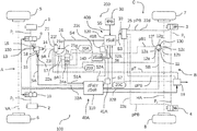
- the embodiment in accordance with FIG. 1 relates to a pneumatic EBS brake system 100 in a commercial vehicle 200 , said brake system being electronically controlled, having wheel brakes 1 , 2 , 3 , 4 at the wheels 5 , 6 , 7 , 8 .
- the wheel brakes 1 , 2 , 3 , 4 are actuated in accordance with the illustrated embodiment in three brake circuits A, B, C, wherein a first brake circuit A relates to the wheel brakes 1 , 2 at the wheels 5 , 6 of a front axle VA and a second and a third brake circuit B, C relate to the wheel brakes 3 , 4 at the wheels 7 , 8 of a rear axle HA.
- ABS brake valves 9 , 10 are connected respectively upstream of the wheel brakes 1 , 2 of the first brake circuit A on the wheels 5 , 6 of the front axle VA so as to regulate a braking pressure p 1 , p 2 in dependence upon an identified ABS brake slip.
- an axle modulator 11 is connected upstream of the wheel brakes 3 , 4 on the driven wheels 7 , 8 of the rear axle HA and said axle modulator may electronically and pneumatically regulate the braking pressure p 3 , p 4 that is output in a controlled and known manner to the individual wheel brakes 3 , 4 and likewise herein may take into account any brake slip at the rear wheels 7 , 8 .
- the axle modulator 11 and also the ABS brake valves 9 , 10 are electronically controlled via a first control unit 110 (ECU). However, separate control units for the axle modulator 11 and the ABS brake valves 9 , 10 may also be provided, said control units individually actuating the respective valves 9 , 10 , 11 .
- the first brake circuit A comprises as a first control valve a relay valve 13 that comprises a first relay valve control input 14 that is configured in a pneumatic manner and a second relay valve control input 17 that is configured in an electronic manner, relay valve working connections 15 and also a relay valve compressed air connection 16 .
- the relay valve working connections 15 are connected via compressed air lines to the two wheel brakes 1 , 2 of the front axle VA.
- the relay valve compressed air connection 16 connects the relay valve 13 to a first pressure storage container 20 A for the first brake circuit A.
- a relay valve control signal SA that is output by the first control unit 110 and that is transmitted via a first brake valve data line 32 A may be transferred via the second relay control input 17 to the relay valve 13 for the electronic actuation.
- the electronic signal SA may be provided by way of example via a relay valve electronic system 150 that is arranged in the relay valve 13 and the valves that are arranged in the relay valve 13 , by way of example 3/2 directional control valves, are actuated by means of said relay valve electronic system in order to generate a pressure that corresponds to the electronic signal SA.
- a relay valve control pressure pA that is output by a bypass valve 21 is provided to the relay valve 13 via the first relay valve control input 14 for the pneumatic actuation, wherein the relay valve control pressure pA in accordance with this embodiment is predetermined in dependence upon a position of the bypass valve 21 either by an actuating device, by way of example a pneumatic brake valve 24 a , in particular a foot brake valve, by means of a manual actuation of a brake pedal by the driver, or by means of a second control unit 120 that in particular electronically controls a parking brake valve 25 .
- an actuating device by way of example a pneumatic brake valve 24 a , in particular a foot brake valve, by means of a manual actuation of a brake pedal by the driver, or by means of a second control unit 120 that in particular electronically controls a parking brake valve 25 .
- the relay valve 13 outputs the braking pressures p 1 , p 2 in a controlled manner to the wheel brakes 1 , 2 of the front axle VA depending upon the prevailing relay valve control pressure pA at the first relay valve control input 14 or the prevailing relay valve control signal SA at the second relay valve control input 17 , wherein the relay valve 13 outputs the compressed air in a controlled manner from the first pressure storage container 20 A proportionally to the relay valve control pressure pA or in dependence upon the predetermined relay valve control signal SA to the wheel brakes 1 , 2 of the front axle VA.
- the wheel brakes 1 , 2 of the front axles VA may be vented via the relay valve 13 in order to reduce the pressure, by way of example via a relay valve venting connection 18 , in dependence upon the relay valve control pressure pA or the relay valve control signal SA.
- a redundancy function is integrated in the first control valve or in the relay valve 13 and it is possible using said redundancy function to automatically fall back from the electrical actuation via the relay valve control signal SA to a pneumatic actuation via the relay valve control pressure pA in the event of by way of example a defect or a failure being present in the electronic actuation by means of the first control unit 110 .
- a 2 channel axle modulator is provided for the second brake circuit B as a second control valve of the axle modulator 11 , said 2 channel axle modulator pneumatically regulating the braking pressures p 3 , p 4 independently of one another and outputting said braking pressures to the respective service brakes 3 , 4 .
- a pneumatic working pressure that is provided at an axle modulator compressed air connection 12 a is output proportionally in a controlled manner at a corresponding level from a second pressure storage container 20 B to axle modulator working connections 12 c or 12 b , wherein a first axle modulator working connection 12 c is connected via compressed air lines to the right-hand side rear wheel brake 3 and a second axle modulator working connection 12 b is connected to the left rear wheel brake 4 .
- the corresponding braking pressure p 3 or p 4 may be reduced by means of a venting procedure via an axle modulator venting connection 12 g.
- the specification for increasing pressure, maintaining pressure or reducing pressure at the rear axle HA may be controlled by an axle modulator electronic system 130 that is integrated in the axle modulator 11 , wherein the first control unit 110 for this purpose electronically predetermines an axle modulator control signal SB via a second brake valve data line 32 B and a first axle modulator control input 12 e , said axle modulator control signal determining the braking pressure p 3 , p 4 that is to be output by the axle modulator 11 in a controlled manner, with the result that by way of example a vehicle desired deceleration zSoll that is predetermined by a third control unit 140 in an automated manner may be implemented or it is possible to react to an ABS brake slip.
- a redundancy function is also integrated in the second control valve or in the axle modulator 11 and it is possible with said redundancy function to automatically fall back from the electrical actuation via the axle modulator control signal SB to a pneumatic actuation via a brake valve axle modulator control pressure pB 1 that is prevailing at a second axle modulator control input 12 f .
- the redundancy function may be used by way of example if a defect or a failure is discovered in the electronic actuation by means of the first control unit 110 or in the axle modulator electronic system 130 or during the transmission of the axle modulator control signal SB from the first control unit 110 to the axle modulator electronic system 130 .
- the braking pressure p 3 , p 4 is consequently no longer output in dependence upon the electrically predetermined axle modulator control signal SB but rather in dependence upon the brake valve axle modulator control pressure pB 1 that is prevailing at the second axle modulator control input 12 f and that is predetermined in accordance with this embodiment by the pneumatic brake valve 24 a.
- the pneumatic brake valve 24 a outputs brake valve control pressures pA 1 , pB 1 in a controlled manner proportionally to an actuating travel ds that is predetermined by the driver by means of actuating a brake pedal, wherein the actuation or the actuating travel ds by way of example may be converted in the first control unit 110 into a deceleration request that is described below as a driver deceleration zFahr.
- a brake valve relay valve control pressure pA 1 is output in a controlled manner from the pneumatic brake valve 24 a via a first compressed air line 22 a to the bypass valve 21 and for the second brake circuit B the brake valve axle modulator control pressure pB 1 is output in a controlled manner via a third compressed air line 22 c to the axle modulator 11 .
- the actuation by the driver may be transmitted via the relay valve control signal SA to the relay valve 13 in the form of the driver deceleration zFahr that is converted in the first control unit 110 .
- the axle modulator 11 is electrically actuated corresponding to the driver deceleration zFahr that is transmitted via the axle modulator signal SB.
- the electronically controlled parking brake valve 25 outputs parking brake valve control pressures pPB in a controlled manner to the third brake circuit C in dependence upon a request that is predetermined electronically via a parking brake signal S 3 , wherein for this purpose the parking brake valve control pressure pPB is output directly to the wheel brakes 3 , 4 of the rear axle HA via a fourth and a fifth compressed air line 22 d , 22 e respectively.
- the request that is predetermined in an electronic manner is transmitted electronically via a parking brake data line 33 via the parking brake signal S 3 from a second control unit 120 .
- the second control unit 120 is preferably integrated in the parking brake valve 25 with the result that the transmission may also be omitted and the second control unit 120 directly assumes the control of the parking brake valve 25 in dependence upon the parking brake signal S 3 .
- This request may represent by way of example a parking brake specification fPB that is predetermined by a parking brake function 30 by the driver or in the redundancy case may be the vehicle desired deceleration zSoll that is transmitted from the third control unit 140 to the second control unit 120 with the result that the vehicle desired deceleration zSoll may also be implemented in the redundancy case at least in part by the parking brake valve 25 via the third brake circuit C.
- a bypass signal S 4 that represents the vehicle desired deceleration zSoll is simultaneously transmitted electronically by said second control unit via a bypass signal line 26 to the bypass valve 21 .
- the relay valve control pressure pA for the relay valve 13 in the first brake circuit A may consequently be output in the redundancy case in accordance with the embodiment in FIG. 1 by said brake circuit to the bypass valve 21 that is allocated to the first brake circuit A as follows:
- the bypass valve 21 is pneumatically connected via the first compressed air line 22 a to the pneumatic brake valve 24 a and electrically via the bypass signal line 26 to the second control unit 120 that controls the parking brake valve 25 .
- the bypass valve 21 comprises a so-called select-high valve 21 j and functions in such a manner that said bypass valve outputs a relay valve control pressure pA in a controlled manner, which implements either the via the electrical bypass signal S 4 that transmits the vehicle desired deceleration zSoll, or via the pneumatic brake valve relay valve control pressure pA 1 that is characterized by the driver deceleration zFahr that is requested.
- the bypass valve 21 may be configured for this purpose as is illustrated in FIG. 5 a . Accordingly, the bypass valve 21 comprises a bypass compressed air connection 21 a via which the bypass valve 21 is connected to the first pressure storage container 20 A for the first brake circuit A and furthermore may be supplied with compressed air.
- An electrical actuation may take place via the bypass electronic system 21 d in the bypass valve 21 using an inlet valve 21 b and an outlet valve 21 c , wherein, depending upon the prevailing bypass signal S 4 and consequently the requested vehicle desired deceleration zSoll at a first bypass control input 21 e , the inlet valve 21 b is opened for a pressure increase or the outlet valve 21 c is opened for a reduction in pressure or the two valves 21 b , 21 c are closed to maintain pressure.
- bypass control pressure pC is consequently set by means of the inlet valve 21 b and the outlet valve 21 c , said bypass control pressure being characterized by the level of the vehicle desired deceleration zSoll.
- the bypass valve 21 may be pneumatically actuated via a second bypass control input 21 g via which the brake valve relay valve control pressure pA 1 is received.
- the bypass control pressure pC and also the brake valve relay valve control pressure pA 1 are guided to a select-high valve 21 j in the bypass valve 21 that only outputs the greater of the two control pressures pC, pA 1 .
- the select-high valve 21 j is configured by way of example as a double non-return valve.
- the greater of the two control pressures pC, pA 1 is subsequently relayed as a relay valve control pressure pA to a bypass output 21 i that is connected to the relay valve 13 .
- bypass valve 21 may also be arranged directly in the relay valve 13 or alternatively in the pneumatic brake valve 24 a.
- the wheels 7 , 8 of the rear axle HA may be braked via the wheel brakes 3 , 4 by means of the parking brake valve 25 (third brake circuit C) in a controlled manner and/or may be braked by means of the pneumatic brake valve 24 a (second brake circuit B) in a controlled manner, wherein a braking procedure is performed directly by means of the parking brake valve 25 and by means of the pneumatic brake valve 24 a via the axle modulator 11 .
- the wheel brakes 3 , 4 of the rear axle HA may be configured for this purpose preferably as combined service and spring-type brake cylinders with the result that the wheels 7 , 8 of the rear axle HA may be braked via the braking pressure p 3 , p 4 that is output by the axle modulator 11 and/or may be braked via the parking brake valve control pressure pPB that is predetermined by the parking brake valve 25 .
- the pneumatic braking valve 24 a is coupled to the pressure storage container 20 A, 20 B so as to provide the brake valve relay valve control pressure pA 1 and the brake valve axle modulator control pressure pB 1 , said pressure storage container providing compressed air for the respective brake circuit A, B.
- the parking brake valve 25 is connected to a third pressure storage container 20 C with the result that the parking brake valve control pressure pPB may be predetermined for the third brake circuit C.
- a trailer control valve 19 is provided that likewise is supplied with compressed air via the third pressure storage container 20 C and is used to brake a trailer that is not illustrated here.
- the control procedure of the electronic brake system 100 may take place as follows:
- the system is an electronically controlled pneumatic brake system 100 (EBS brake system)
- the relay valve 13 and the axle modulator 11 are electrically actuated in the normal operation of the vehicle 200 by the first control unit 110 in that the relay valve control signal SA is transmitted electrically to the relay valve 13 via the second relay valve control input 17 , said relay valve then outputting a corresponding braking pressure p 1 , p 2 in a controlled manner to the wheel brakes 1 , 2 of the front axle VA.
- EBS brake system electronically controlled pneumatic brake system 100
- the axle modulator control signal SB is transmitted electrically via the first axle modulator control input 12 e to the axle modulator 11 , said axle modulator control signal then setting the corresponding braking pressure p 3 , p 4 at the wheel brakes 3 , 4 of the rear axle HA in accordance with the above embodiments.
- the relay valve control signal SA or the axle modulator control signal SB are preferably predetermined by the first control unit 110 via the first and second brake valve data line 32 A, 32 B.
- the first control unit 110 determines the control signals SA, SB herein either in dependence upon the vehicle desired deceleration zSoll that is predetermined by the third control unit 140 , wherein the third control unit 140 is allocated to a controlled electronic regulating system that is configured so as to control the vehicle 200 in an automated manner or however in dependence upon the actuating travel ds that is predetermined by the pneumatic brake valve 24 a by means of a manual actuation by the driver, said actuating travel being converted in the first control unit 110 into the driver deceleration zFahr.
- the first control unit 110 generates for this purpose the corresponding relay valve control signal SA for the first brake circuit A and the axle modulator control signal SB for the second brake circuit B from a first actuating signal S 1 A of the pneumatic brake valve 24 a , said first actuating signal transmitting the actuating travel ds, and/or from a first request signal S 2 A of the third control unit 140 , said first request signal transmitting the vehicle desired deceleration zSoll so as to initiate the corresponding deceleration zSoll, zFahr.
- the relay valve 13 or the axle modulator 11 is only actuated pneumatically via the prevailing relay valve control pressure pA or the brake valve axle modulator control pressure pB 1 in order to output the braking pressures p 1 , p 2 , p 3 , p 4 to the wheel brakes 1 , 2 , 3 , 4 in a controlled manner. Consequently, a switch is made for the actuation of the corresponding control valves 11 , 13 from the electronic control inputs 17 , 12 e to the pneumatic control inputs 14 , 12 f of the respective control valve 11 , 13 .
- the braking effect that is performed by means of the wheel brakes 1 , 2 , 3 , 4 in the redundancy case is in particular dependent upon which fallback level or which redundant actuation the operation falls back to.
- the wheel brakes 1 , 2 , 3 , 4 are thus actuated in a second electronic pneumatic fallback level merely in dependence upon the parking brake signal S 3 that is generated by the second control unit 120 and also upon the bypass signal S 4 .
- the request signal S 2 that transmits the vehicle desired deceleration zSoll is transmitted from the third control unit 140 via a second request signal S 2 B to the second control unit 120 , said second control unit generating the parking brake signal S 3 in dependence upon said second request signal and therefore controlling the parking brake valve 25 .
- bypass signal S 4 is generated in dependence upon the vehicle desired deceleration zSoll in the second control unit 120 and is transmitted to the bypass valve 21 .
- the second control unit 120 may ask the first control unit 110 via a monitoring signal S 7 whether a failure or a defect is present in the electronic system and react accordingly thereto.
- the parking brake valve control pressure pPB is output via the fourth and the fifth compressed air line 22 d , 22 e to the wheel brakes 3 , 4 of the rear axle HA in dependence upon the parking brake signal S 3 and a braking procedure is consequently directly performed.
- the bypass signal S 4 is transmitted to the bypass valve 21 via the bypass signal line 26 . Since the pneumatic brake valve 24 a is not actuated, the brake valve relay valve control pressure pA 1 is approximately zero with the result that the bypass control pressure pC that is predetermined in dependence upon the vehicle desired deceleration zSoll is output in a controlled manner by the bypass valve 21 as a relay valve control pressure pA to the relay valve 13 .
- the relay valve 13 will output in a controlled manner a braking pressure p 1 , p 2 that is in proportion to the relay valve control pressure pA to the wheel brakes 1 , 2 of the front axle VA in order to initiate the vehicle desired deceleration zSoll that is requested in an automated manner by the second control unit 120 or by the third control unit 140 .
- the first control unit 110 and the second control unit 120 may be operated electrically separately from one another, wherein a first electrical circuit 40 A is provided for the first control unit 110 and a second electrical circuit 40 B is provided for the second control unit 120 .
- the first and also the second control unit 110 , 120 may be supplied with energy via a first energy supply 41 A and only the second control unit 120 is connected to a second energy supply 41 B with the result that, in the event of an electronic defect in the first energy supply 41 A, the second electrical circuit 40 B having the second control unit 120 may continue to perform its functions in a redundant manner.
- the third control unit 140 that in particular in the automated operation predetermines the vehicle desired deceleration zSoll via the first or the second request signal S 2 A, S 2 B for the first and the second control unit 110 , 120 , is connected both to the first as well as to the second energy supply 41 A, 41 B with the result that said third control unit in the case of a failure of the first electrical circuit 40 A or in the case of a failure of the second electrical circuit 40 B may be supplied with energy in the two cases.
- the respective data lines 32 A, 32 B, 33 , 26 that are configured by way of example as a bus system, in particular a CAN bus, are arranged in the circuit 40 A, 40 B that is allocated to the respective control unit 110 , 120 with the result that in the case of a defect a transmission of data is also ensured.
- the pneumatic brake valve 24 a is simultaneously actuated in the redundancy case, by way of example by means of a mechanical actuation by the driver, by way of example in an emergency braking situation, or via an electronically controlled mechanical actuation of the brake pedal, it is crucial for the wheel brakes 1 , 2 of the front axle VA whether the brake valve relay valve control pressure pA 1 or the bypass control pressure pC is greater, said bypass control pressure being determined by means of the vehicle desired deceleration zSoll, in other words whether a greater deceleration zFahr, zSoll is predetermined by means of the actuation of the brake pedal or by means of the automated specification.
- the braking pressure p 1 , p 2 for the wheel brakes 1 , 2 of the front axle VA is output in a controlled manner by means of the relay valve 13 in dependence upon the specification from the second control unit 120 or in dependence upon the specification of the pneumatic brake valve 24 a.
- an actuation of the axle modulator 11 also occurs simultaneously and furthermore a braking pressure p 3 , p 4 that is in proportion to said actuation is output to the wheel brakes 3 , 4 of the rear axle HA.
- the parking brake valve 25 actuates the wheel brakes 3 , 4 of the rear axle HA using a parking brake valve control pressure pPB that is dependent upon the vehicle desired deceleration zSoll with the result that depending upon the embodiment of the rear wheel brakes 3 , 4 , by way of example having combined service brake and spring-type brake cylinders, a braking force addition of the braking pressures p 3 with pPB or p 4 with pPB takes place at the respective wheel brakes 3 , 4 .
- the electronic braking request is overridden in accordance with this embodiment at least at the front axle VA, if this braking request is greater.
- a second bypass valve 23 may be provided that functions in a similar manner to the first bypass valve 21 .
- an axle modulator control pressure pB is predetermined at the axle modulator 11 by means of the second bypass valve 23 , wherein the axle modulator control pressure pB is output in a controlled manner either in dependence upon the vehicle desired deceleration zSoll that is predetermined by the bypass signal S 4 or in dependence upon the brake valve axle modulator control pressure pB 1 depending upon which predetermines the greater deceleration request zSoll, zFahr.
- a vehicle desired deceleration zSoll that is predetermined by the second control unit 120 may also be output in a controlled manner via the axle modulator 11 to the rear wheel brakes 3 , 4 .
- the braking force distribution and also the braking effect may be further improved in the redundancy case.
- the brake system 100 may be configured as an electronically controlled pneumatic brake system 100 , as illustrated in FIG. 3 , said brake system comprising at the two vehicle axles VA, HA respectively ABS brake valves 9 , 10 and also wheel rotational speed sensors 35 in order to be able to identify a brake slip at all four wheels 5 , 6 , 7 , 8 and to be able to react to said brake slip.
- a braking pressure p 1 , p 2 , p 3 , p 4 is provided via the control valves 11 , 13 respectively at the wheel brakes 1 , 2 , 3 , 4 , wherein this braking pressure may be maintained or reduced by means of the ABS brake valves 9 , 10 in dependence upon the wheel brake rotational speed sensors 35 in a case of an identified braking slip.
- the two control valves 11 , 13 are configured in accordance with this embodiment as relay valves respectively having respectively a 3/2 directional control valve with the result that both an electronic actuation via the electronic relay valve control input 17 as well as a pneumatic actuation via the pneumatic relay valve control input 14 is rendered possible.
- the pneumatic relay valve control input 14 is configured as a 3/2 directional control valve that permits a corresponding pressure to flow into the relay valve 11 , 13 depending upon the control signal SA, SB that is present. If the control valves 11 , 13 can no longer be actuated via the control signals SA, SB, a pneumatic control pressure pA and, where appropriate, pB is thus set at the pneumatic relay valve control input 14 corresponding to the brake system 100 in the FIGS. 1 and 2 .
- an electrical actuating device 24 b is provided as an actuating device that only generates electrical request signals S 1 A, S 1 B in dependence upon the actuating travel ds that is predetermined by means of the actuation of the brake pedal by the driver.
- the pneumatic procedure of outputting a control pressure in a controlled manner is consequently omitted in accordance with this embodiment by means of the actuating device 24 b .
- the first request signal S 1 A is transmitted to the first control unit 110 that calculates from said first request signal the driver deceleration zFahr in order to predetermine via said driver deceleration the corresponding control signals SA, SB for the respective brake circuit A, B.
- the control valves 11 , 13 are electrically actuated via said control signals.
- the braking request is predetermined in a redundant manner by means of the second control unit 120 , wherein the specification is performed either in dependence upon the vehicle desired deceleration zSoll that is predetermined in an automated manner or in dependence upon the driver deceleration zFahr that results from the actuating travel ds and is calculated in the second control unit 120 .
- the actuation or the actuating travel ds is transmitted via a second request signal S 1 B from the electrical actuating device 24 b to the second control unit 120 and the driver deceleration zFahr is determined therefrom.
- the second control unit 120 then performs a check as to whether the driver deceleration zFahr or the vehicle desired deceleration zSoll is greater.
- the greater of the two decelerations zSoll, zFahr is transmitted electronically via the bypass signal S 4 to the bypass valve 21 and via the parking brake signal S 3 to the parking brake valve 25 , said bypass valve and parking brake valve then outputting in a controlled manner a corresponding relay valve control pressure pA for the first brake circuit A or parking brake control pressure pPB for the third brake circuit C.
- the bypass valve 21 for this embodiment does not comprise a select-high valve 21 j since the procedure of deciding the greater deceleration zFahr, zSoll has already been performed in the second control unit 120 . Furthermore, a pneumatic input 21 g is not provided. Accordingly, only one inlet valve 21 b and one outlet valve 21 c are provided that generate in a controlled manner the bypass control pressure pC from the bypass electronic system 21 d depending upon the bypass signal S 4 that is prevailing, said bypass control pressure then being output as a relay valve control pressure pA to the bypass output 21 i.
- a double electronically controlled brake system is therefore proposed in FIG. 4 , said brake system obtaining an electrical specification zSoll, ds from both the third control unit 140 for the automated operation as well as from the electrical actuating device 24 b , said specification then being implemented in an electric pneumatic manner by means of the wheel brakes 1 , 2 , 3 , 4 .
- a trailer control valve 19 may output a prevailing trailer control pressure pT in order to also be able to actuate wheel brakes of a trailer in the redundancy case.
- the trailer control pressure pT is predetermined by way of example by means of the relay valve control pressure pA that is output in a controlled manner in the first brake circuit A in the redundancy case.
- the trailer is actuated when at a standstill via the parking brake valve 25 , wherein the actuation is predetermined in dependence upon the parking brake specification fPB by way of example by means of the driver activating a parking brake function 30 when at a standstill.
- the parking brake valve control pressure pPB is likewise supplied via the fourth and the fifth compressed air line 22 d , 22 e to the wheel brakes 3 , 4 on the rear axle HA of the vehicle 200 with the result that a safe parking procedure of the vehicle 200 and also of the trailer may be ensured in a parking situation.
- the second control unit 120 in the case only outputs a braking request to the parking brake valve 25 with the result that the parking brake function that is predetermined by the driver is only initiated at the rear axle HA and also where appropriate at the trailer via the trailer control valve 19 .
- a parking brake function may also be implemented during the automated driving operation so as to park the vehicle 200 in that an automatic signal S 6 is transmitted from the third control unit 140 to the second control unit 120 that then in particular via the parking brake valve 25 holding the vehicle 200 at a standstill and consequently being able to securing the vehicle 200 in an automated manner in a parking situation.
- the automated parking braking procedure may also be implemented using the wheel brakes 1 , 2 of the front axle VA when the vehicle is at a standstill and without the presence of a redundancy case also by means of accordingly generating the bypass signal S 4 .
- the recitation of “at least one of A, B and C” should be interpreted as one or more of a group of elements consisting of A, B and C, and should not be interpreted as requiring at least one of each of the listed elements A, B and C, regardless of whether A, B and C are related as categories or otherwise.
- the recitation of “A, B and/or C” or “at least one of A, B or C” should be interpreted as including any singular entity from the listed elements, e.g., A, any subset from the listed elements, e.g., A and B, or the entire list of elements A, B and C.
Landscapes
- Engineering & Computer Science (AREA)
- Transportation (AREA)
- Mechanical Engineering (AREA)
- Regulating Braking Force (AREA)
- Braking Systems And Boosters (AREA)
- Valves And Accessory Devices For Braking Systems (AREA)
Applications Claiming Priority (3)
| Application Number | Priority Date | Filing Date | Title |
|---|---|---|---|
| DE102016005318.6 | 2016-05-02 | ||
| DE102016005318.6A DE102016005318A1 (de) | 2016-05-02 | 2016-05-02 | Elektronisch steuerbares pneumatisches Bremssystem in einem Nutzfahrzeug sowie Verfahren zum elektronischen Steuern eines pneumatischen Bremssystems. |
| PCT/EP2017/000326 WO2017190820A1 (de) | 2016-05-02 | 2017-03-13 | Elektronisch steuerbares pneumatisches bremssystem in einem nutzfahrzeug sowie verfahren zum elektronischen steuern eines pneumatischen bremssystems |
Publications (2)
| Publication Number | Publication Date |
|---|---|
| US20190152459A1 US20190152459A1 (en) | 2019-05-23 |
| US11052892B2 true US11052892B2 (en) | 2021-07-06 |
Family
ID=58347308
Family Applications (1)
| Application Number | Title | Priority Date | Filing Date |
|---|---|---|---|
| US16/095,942 Active 2038-01-21 US11052892B2 (en) | 2016-05-02 | 2017-03-13 | Electronically controllable pneumatic brake system in a utility vehicle and method for electronically controlling a pneumatic brake system |
Country Status (7)
| Country | Link |
|---|---|
| US (1) | US11052892B2 (de) |
| EP (1) | EP3452346B1 (de) |
| JP (1) | JP6894919B2 (de) |
| KR (1) | KR102079195B1 (de) |
| CN (1) | CN108883755B (de) |
| DE (1) | DE102016005318A1 (de) |
| WO (1) | WO2017190820A1 (de) |
Cited By (3)
| Publication number | Priority date | Publication date | Assignee | Title |
|---|---|---|---|---|
| US20220055583A1 (en) * | 2019-05-28 | 2022-02-24 | Zf Cv Systems Hannover Gmbh | Electronically controlled pneumatic brake system with two single-channel axle modulators and abs valves, and vehicle having a brake system of this type |
| US11840167B2 (en) | 2020-03-06 | 2023-12-12 | Howe & Howe Inc. | Failsafe parking brake manual override |
| US11932229B2 (en) | 2019-03-15 | 2024-03-19 | Zf Cv Systems Europe Bv | Electronically controllable braking system having two fall-back levels |
Families Citing this family (50)
| Publication number | Priority date | Publication date | Assignee | Title |
|---|---|---|---|---|
| DE102015011296A1 (de) * | 2015-09-02 | 2017-03-02 | Wabco Gmbh | Elektronisch steuerbares pneumatisches Bremssystem in einem Nutzfahrzeug sowie Verfahren zum elektronischen Steuern eines pneumatischen Bremssystems |
| DE102016010464A1 (de) * | 2016-08-31 | 2018-03-01 | Wabco Gmbh | Elektronisch steuerbares pneumatisches Bremssystem in einem Nutzfahrzeug sowie Verfahren zum elektronischen Steuern eines pneumatischen Bremssystems in einem Nutzfahrzeug |
| DE102016010461A1 (de) | 2016-08-31 | 2018-03-01 | Wabco Gmbh | Verfahren zum elektronischen Steuern einer Bremsanlage in einem automatisiert steuerbaren Nutzfahrzeug-Gespann sowie elektronisch steuerbare Bremsanlage in einem automatisiert steuerbaren Nutzfahrzeug-Gespann |
| DE102017125696A1 (de) | 2017-11-03 | 2019-05-09 | Ipgate Ag | Hydraulische Einrichtung und Kolben-Zylinder Einheit Dichtungssystem für derartige Einrichtungen, insbesondere für Brems- und Kupplungseinrichtungen für automatisiertes Fahren, sowie deren Komponenten |
| CN108263367B (zh) * | 2018-01-03 | 2023-09-01 | 温州瑞立科密汽车电子有限公司 | 商用车电子驻车系统 |
| US10850716B2 (en) | 2018-05-31 | 2020-12-01 | Bendix Commercial Vehicle Systems Llc | System and method for controlling an automated braking application |
| DE102018113299A1 (de) * | 2018-06-05 | 2019-12-05 | Wabco Gmbh | Elektronische Einrichtung zum Steuern eines elektro-pneumatischen Feststellbremskreises, ein Feststellbrems-System für ein Fahrzeug und ein Verfahren zum Steuern eines elektro-pneumatischen Feststellbremskreises |
| US10538226B1 (en) * | 2018-07-06 | 2020-01-21 | Starsky Robotics, Inc. | Vehicle braking system and method |
| DE102018118720A1 (de) | 2018-08-01 | 2020-02-06 | Wabco Gmbh | Verfahren zum automatisierten elektronischen Steuern eines Bremssystems in einem Nutzfahrzeug mit ABS Sicherung |
| CN109367528A (zh) * | 2018-08-28 | 2019-02-22 | 南京金龙客车制造有限公司 | 一种自动驻车系统及其控制方法 |
| DE102018123750A1 (de) | 2018-09-14 | 2020-03-19 | Wabco Gmbh | Elektropneumatische Anhängersteuerventileinheit für Nordamerika |
| EP3626557B1 (de) * | 2018-09-18 | 2023-04-12 | KNORR-BREMSE Systeme für Nutzfahrzeuge GmbH | Bremsensystem für ein fahrzeug |
| EP3626558B1 (de) * | 2018-09-18 | 2022-10-26 | KNORR-BREMSE Systeme für Nutzfahrzeuge GmbH | Bremsensystem für ein fahrzeug |
| EP3626560B1 (de) * | 2018-09-18 | 2022-10-26 | KNORR-BREMSE Systeme für Nutzfahrzeuge GmbH | Bremsensystem für ein fahrzeug und fahrzeug |
| EP3626559B1 (de) | 2018-09-18 | 2022-10-26 | KNORR-BREMSE Systeme für Nutzfahrzeuge GmbH | Bremsensystem für ein fahrzeug |
| DE102018219378A1 (de) * | 2018-11-13 | 2020-05-14 | Knorr-Bremse Systeme für Nutzfahrzeuge GmbH | Redundantes Bremssystem und Verfahren zum Betrieb eines solchen Bremssystems |
| WO2020158585A1 (ja) * | 2019-01-29 | 2020-08-06 | 日立オートモティブシステムズ株式会社 | ブレーキシステム |
| DE102019106243A1 (de) * | 2019-03-12 | 2020-09-17 | Wabco Gmbh | Elektropneumatisches Bremssystem für Nutzfahrzeug |
| DE102019106274A1 (de) * | 2019-03-12 | 2020-09-17 | Wabco Gmbh | Elektronisch steuerbares Bremssystem mit zwei Rückfallebenen (alternative Ausführung) |
| DE102019118895A1 (de) * | 2019-07-12 | 2021-01-14 | Knorr-Bremse Systeme für Nutzfahrzeuge GmbH | Parkbremseinrichtung für ein Nutzfahrzeug |
| WO2021026048A2 (en) * | 2019-08-06 | 2021-02-11 | Locomation, Inc. | Complementary brake actuation retrofit |
| EP3789255B1 (de) * | 2019-09-09 | 2023-11-08 | KNORR-BREMSE Systeme für Nutzfahrzeuge GmbH | Bremsensystem für ein nutzfahrzeug |
| WO2021064443A1 (en) * | 2019-09-30 | 2021-04-08 | Power Stow International Aps | Airport vehicle having an anti-collision system and method for operating a vehicle having an anti-collision system |
| CN112572392B (zh) * | 2019-09-30 | 2022-04-26 | 湖南中车智行科技有限公司 | 一种车辆制动系统及车辆制动系统控制方法 |
| CN110667548B (zh) * | 2019-10-17 | 2021-01-15 | 清华大学 | 线控制动系统冗余制动方法、系统及存储介质 |
| EP4048565B1 (de) * | 2019-10-22 | 2024-07-24 | Continental Automotive Technologies GmbH | Bremssystem für ein kraftfahrzeug |
| DE102020130277A1 (de) * | 2019-11-18 | 2021-05-20 | WABCO Global GmbH | Ausfallsicherheitsventileinheit, Elektronisch steuerbares pneumatisches Bremssystem, Verfahren zum Betreiben eines Bremssystems |
| DE102019131110A1 (de) * | 2019-11-18 | 2021-05-20 | Wabco Europe Bvba | Bremssystem mit sicherer Notstoppfunktion und Verfahren hierzu |
| DE102019133010A1 (de) | 2019-12-04 | 2021-06-10 | Zf Cv Systems Global Gmbh | Ausfallsicherheitsventileinheit für eine Parkbremsfunktion sowie Parkbremsventilanordnung |
| DE102019133011A1 (de) * | 2019-12-04 | 2021-06-10 | Zf Cv Systems Global Gmbh | Monostabil und fehlertolerant ausgelegte Feststellbremsventilanordnung |
| DE102019133012A1 (de) * | 2019-12-04 | 2021-06-10 | Zf Cv Systems Global Gmbh | Elektrisch steuerbares pneumatisches Bremssystem mit einem zweikanaligen Druckmodulatorsystem |
| DE102019133373A1 (de) * | 2019-12-06 | 2021-06-10 | Zf Cv Systems Global Gmbh | Verfahren zur Verzögerungsregelung eines Fahrzeuges sowie Bremssystem hierfür |
| CN114829218B (zh) * | 2019-12-16 | 2024-07-30 | 沃尔沃卡车集团 | 挂车连接状态确定和共享 |
| CN111267816B (zh) * | 2020-02-22 | 2024-07-19 | 吉林大学 | 一种防制动失效的双回路气压制动系统 |
| US11407394B2 (en) * | 2020-03-09 | 2022-08-09 | Bendix Commercial Vehicle Systems Llc | Method and parking brake apparatus for an autonomously drivable vehicle |
| DE102020108072A1 (de) * | 2020-03-24 | 2021-09-30 | Knorr-Bremse Systeme für Nutzfahrzeuge GmbH | Elektronisch gesteuertes Betriebsbremssystem mit auf der Basis eines weiteren Druckluftverbraucherkreises erzeugtem Backup-Steuerdruck |
| US11820341B2 (en) * | 2020-10-01 | 2023-11-21 | Valcrum, Llc | Electrically modulated air brake |
| EP4228941A1 (de) * | 2020-10-14 | 2023-08-23 | ZF CV Systems Europe BV | Bremsdruckmodulator und verwendung eines bremsdruckmodulators |
| EP4001031B1 (de) * | 2020-11-13 | 2024-01-03 | Volvo Truck Corporation | Elektropneumatisches bremssystem für ein fahrzeug mit einem feststellbremssystem als reserveverzögerungssystem |
| DE102020130276A1 (de) | 2020-11-17 | 2022-05-19 | Zf Cv Systems Global Gmbh | Ausfallsicherheitsventileinheit, elektronisch steuerbares pneumatisches Bremssystem, Fahrzeug, Verfahren |
| DE102020132875A1 (de) | 2020-12-09 | 2022-06-09 | Zf Cv Systems Global Gmbh | Verfahren zum Noteinlegen einer Feststellbremse und elektropneumatisches Bremssystem |
| CN114802149B (zh) * | 2021-01-19 | 2023-03-21 | 上海汽车集团股份有限公司 | 一种适用于l3-l5智能驾驶的集成式制动控制系统 |
| DE102021103478A1 (de) | 2021-02-15 | 2022-08-18 | Zf Cv Systems Global Gmbh | Verfahren und Bremssystem zum Notstoppen eines Nutzfahrzeugs |
| DE102021112831A1 (de) | 2021-05-18 | 2022-11-24 | Zf Cv Systems Global Gmbh | Elektropneumatische Baueinheit mit integrierter Ausfallsicherheitsventilanordnung für Mehrfachfehler, elektronisch steuerbares pneumatisches Bremssystem, sowie Verfahren zum Betreiben eines Bremssystems |
| DE102021122501A1 (de) | 2021-08-31 | 2023-03-02 | Zf Cv Systems Global Gmbh | Elektronisch steuerbares pneumatisches Bremssystem mit einer ausfallsicheren Bremsanwendung für einen autonomen Fahrbetrieb mit nur einem Wechselventil |
| CN114030448B (zh) * | 2021-10-27 | 2022-08-05 | 武汉未来幻影科技有限公司 | 一种车辆及控制系统、方法和装置 |
| EP4186760B1 (de) * | 2021-11-29 | 2024-09-25 | KNORR-BREMSE Systeme für Nutzfahrzeuge GmbH | Redundantes steuerungssystem für einen ersten und einen zweiten bremszylinder eines fahrzeugs |
| DE102021131327A1 (de) | 2021-11-30 | 2023-06-01 | Zf Cv Systems Global Gmbh | Ausfallsicheres redundantes Bremssystem mit Druckeinspeisung über einen Entlüftungspfad des primären Modulators |
| DE102021131328A1 (de) | 2021-11-30 | 2023-06-01 | Zf Cv Systems Global Gmbh | Redundanzventilanordnung und Bremssystem mit einer Druckeinsteuerung über redundant ausgebildete ABS Ventile |
| US12065111B1 (en) * | 2023-08-09 | 2024-08-20 | Pressure Drop Technology Integration, Inc. | Air brakes sound effects system |
Citations (21)
| Publication number | Priority date | Publication date | Assignee | Title |
|---|---|---|---|---|
| DE19504394C1 (de) | 1995-02-10 | 1996-03-07 | Wabco Gmbh | Druckmittelbetätigte Fahrzeugbremsanlage |
| DE2818813C3 (de) | 1978-04-28 | 1996-03-21 | Wabco Gmbh | Anordnung zum Verhindern des Durchdrehens einer oder mehrerer angetriebener Räder, insbesondere beim Anfahren |
| DE19750392A1 (de) | 1997-11-13 | 1998-05-28 | Knorr Bremse Systeme | Ausfallsichere elektro-pneumatische Bremssteuerung |
| DE19653264A1 (de) | 1996-12-20 | 1998-06-25 | Bosch Gmbh Robert | Elektronisch steuerbares Bremssystem für Fahrzeuge, insbesondere Nutzfahrzeuge |
| US6659244B2 (en) | 2000-12-04 | 2003-12-09 | Bendix Commerical Vehicle Systems Llc | Integrated foot control valve actuator |
| US20060152075A1 (en) | 2002-08-12 | 2006-07-13 | Knorr-Bremse Systeme Fuer Nutzfahrzeuge Gmbh | Pressure regulator module for a motor vehicle pneumatic braking system |
| US7520572B2 (en) | 2004-04-02 | 2009-04-21 | Bendix Commerical Vehicle Systems Llc | Use of ECU to control brake valve actuator |
| US20100025141A1 (en) * | 2005-12-09 | 2010-02-04 | Uwe Bensch | Electro-Pneumatic Brake Control Device |
| JP2010523384A (ja) | 2007-04-04 | 2010-07-15 | ヴアブコ・ゲゼルシヤフト・ミツト・ベシユレンクテル・ハフツング | 非常釈放機能を持つ車両の駐車制動装置及びこのような駐車制動装置の操作方法 |
| US7866761B2 (en) * | 2003-05-08 | 2011-01-11 | Knorr-Bremse Systeme Fur Nutzfahrzeuge Gmbh | Braking system for vehicles, in particular utility vehicles, comprising at least two separate electronic braking control circuits |
| US20110005874A1 (en) * | 2008-01-07 | 2011-01-13 | Peter Beier | Brake system for a vehicle and brake pedal device for such a brake system |
| US20110012421A1 (en) * | 2008-02-19 | 2011-01-20 | Uwe Bensch | Parking brake for a vehicle and method for operating the parking brake |
| DE102010050578A1 (de) | 2010-11-05 | 2012-05-10 | Wabco Gmbh | System mit Ventileinrichtung für eine pneumatisch betriebene Bremsanlage, Ventileinrichtung, Bremsbestätigungseinrichtung, Anhängersteuerventileinrichtung und Einrichtung zur Steuerung für das System, Bremsanlage, Fahrzeug, Verwendung einer Komponente und Verfahren zum Umrüsten einer Bremsanlage |
| DE102013015949A1 (de) | 2013-09-25 | 2015-03-26 | Wabco Gmbh | Bremssystem und Verfahren zur Kurvenunterstützung |
| DE102014013882A1 (de) | 2013-09-26 | 2015-03-26 | Bendix Commercial Vehicle Systems, Llc | Automatiktraktionsrelaisventildiagnostik unter Verwendung einer Druckwandlerrückkopplung |
| DE102014006615A1 (de) | 2014-05-08 | 2015-11-12 | Wabco Gmbh | Druckmittelbetriebenes Bremssystem für ein Kraftfahrzeug sowie Kraftfahrzeug damit |
| WO2017036569A1 (de) | 2015-09-02 | 2017-03-09 | Wabco Gmbh | Elektronisch steuerbares pneumatisches bremssystem in einem nutzfahrzeug sowie verfahren zum elektronischen steuern eines pneumatischen bremssystems |
| US10093293B2 (en) * | 2014-07-31 | 2018-10-09 | Wabco Gmbh | Brake pressure modulator of an electronic braking system of a utility vehicle |
| US20180362008A1 (en) * | 2015-07-27 | 2018-12-20 | Lionel FARRES | Brake arrangement comprising hybrid brake actuators |
| US10501062B2 (en) * | 2016-08-31 | 2019-12-10 | Wabco Europe Bvba | Electronically controllable pneumatic brake system in a utility vehicle and method for electronically controlling a pneumatic brake system in a utility vehicle |
| US10730500B2 (en) * | 2016-09-21 | 2020-08-04 | Knorr-Bremse Systeme Fuer Nutzfahrzeuge Gmbh | Parking brake device for a utility vehicle |
Family Cites Families (13)
| Publication number | Priority date | Publication date | Assignee | Title |
|---|---|---|---|---|
| DE102006048910A1 (de) | 2006-10-17 | 2008-04-24 | Robert Bosch Gmbh | Ausfallsicheres Parkassistenzsystem |
| JP4492675B2 (ja) * | 2006-11-08 | 2010-06-30 | トヨタ自動車株式会社 | 車両用制動装置 |
| DE102008024180A1 (de) * | 2007-06-19 | 2008-12-24 | Continental Teves Ag & Co. Ohg | Kombinierte Bremsanlage, insbesondere für Kraftfahrzeuge |
| DE102007052439A1 (de) | 2007-11-02 | 2009-05-07 | Wabco Gmbh | Fahrerassistenzsystem |
| DE102008009043B3 (de) | 2008-02-14 | 2009-05-14 | Knorr-Bremse Systeme für Nutzfahrzeuge GmbH | Elektronisch geregeltes Bremssystem mit redundanter Steuerung der Bremsaktuatoren |
| DE102008021822B3 (de) * | 2008-04-11 | 2009-04-09 | Knorr-Bremse Systeme für Nutzfahrzeuge GmbH | Verfahren und Vorrichtung zum Steuern einer Druckluftversorgungseinrichtung beim Ausfall eines Regelkreises eines EBS-Bremssystems |
| US8465107B2 (en) * | 2011-06-15 | 2013-06-18 | Arvinmeritor Technology, Llc | Regenerative air brake module |
| EP2794368B2 (de) | 2011-12-23 | 2021-11-17 | Renault Trucks | Elektronisch gesteuertes pneumatisches bremssystem für ein automobil und automobil mit einem solchen system |
| DE102013007881A1 (de) * | 2013-05-08 | 2014-11-13 | Knorr-Bremse Systeme für Nutzfahrzeuge GmbH | Verfahren zur Abbremsung einer Zugfahrzeug-Anhängerkombination mit reduzierter Anhängerbremskraft abhängig vom Ansprechen des Zugfahrzeug-ABS |
| KR102111909B1 (ko) * | 2013-11-21 | 2020-05-18 | 현대모비스 주식회사 | 전자식 유압 브레이크 시스템 |
| DE102014006613A1 (de) | 2014-05-08 | 2015-11-12 | Wabco Gmbh | Steuergerät für ein druckluftbetriebenes Bremssystem, Bremssystem mit derartigem Steuergerät sowie Fahrzeug mit derartigem Bremssystem |
| DE102014112015A1 (de) | 2014-08-22 | 2016-02-25 | Knorr-Bremse Systeme für Nutzfahrzeuge GmbH | Verfahren zum Steuern einer durch eine Betriebsbremsventileinrichtung betätigten Betriebsbremseinrichtung sowie Betriebsbremseinrichtung |
| DE102014013756C5 (de) | 2014-09-22 | 2018-04-26 | Knorr-Bremse Systeme für Nutzfahrzeuge GmbH | Elektrische Ausrüstung eines Fahrzeugs mit einer wenigstens teilweise elektrischen Brems- und Lenkeinrichtung mit hoher Verfügbarkeit |
-
2016
- 2016-05-02 DE DE102016005318.6A patent/DE102016005318A1/de active Pending
-
2017
- 2017-03-13 EP EP17711087.1A patent/EP3452346B1/de active Active
- 2017-03-13 JP JP2018551151A patent/JP6894919B2/ja active Active
- 2017-03-13 WO PCT/EP2017/000326 patent/WO2017190820A1/de unknown
- 2017-03-13 KR KR1020187023600A patent/KR102079195B1/ko active IP Right Grant
- 2017-03-13 CN CN201780020183.5A patent/CN108883755B/zh active Active
- 2017-03-13 US US16/095,942 patent/US11052892B2/en active Active
Patent Citations (28)
| Publication number | Priority date | Publication date | Assignee | Title |
|---|---|---|---|---|
| DE2818813C3 (de) | 1978-04-28 | 1996-03-21 | Wabco Gmbh | Anordnung zum Verhindern des Durchdrehens einer oder mehrerer angetriebener Räder, insbesondere beim Anfahren |
| DE19504394C1 (de) | 1995-02-10 | 1996-03-07 | Wabco Gmbh | Druckmittelbetätigte Fahrzeugbremsanlage |
| US5624163A (en) | 1995-02-10 | 1997-04-29 | Wabco Gmbh | Pressure medium actuated vehicle braking system |
| DE19653264A1 (de) | 1996-12-20 | 1998-06-25 | Bosch Gmbh Robert | Elektronisch steuerbares Bremssystem für Fahrzeuge, insbesondere Nutzfahrzeuge |
| DE19750392A1 (de) | 1997-11-13 | 1998-05-28 | Knorr Bremse Systeme | Ausfallsichere elektro-pneumatische Bremssteuerung |
| US6659244B2 (en) | 2000-12-04 | 2003-12-09 | Bendix Commerical Vehicle Systems Llc | Integrated foot control valve actuator |
| US20060152075A1 (en) | 2002-08-12 | 2006-07-13 | Knorr-Bremse Systeme Fuer Nutzfahrzeuge Gmbh | Pressure regulator module for a motor vehicle pneumatic braking system |
| EP1530529B1 (de) | 2002-08-12 | 2007-05-23 | KNORR-BREMSE SYSTEME FÜR NUTZFAHRZEUGE GmbH | Druckregelmodul für eine druckluft-bremsanlage eines fahrzeugs |
| US7866761B2 (en) * | 2003-05-08 | 2011-01-11 | Knorr-Bremse Systeme Fur Nutzfahrzeuge Gmbh | Braking system for vehicles, in particular utility vehicles, comprising at least two separate electronic braking control circuits |
| US7520572B2 (en) | 2004-04-02 | 2009-04-21 | Bendix Commerical Vehicle Systems Llc | Use of ECU to control brake valve actuator |
| EP1730006B1 (de) | 2004-04-02 | 2012-12-26 | Bendix Commercial Vehicle Systems, LLC | Verwendung einer ecu zur steuerung eines bremsstellglieds |
| US20100025141A1 (en) * | 2005-12-09 | 2010-02-04 | Uwe Bensch | Electro-Pneumatic Brake Control Device |
| JP2010523384A (ja) | 2007-04-04 | 2010-07-15 | ヴアブコ・ゲゼルシヤフト・ミツト・ベシユレンクテル・ハフツング | 非常釈放機能を持つ車両の駐車制動装置及びこのような駐車制動装置の操作方法 |
| US20110005874A1 (en) * | 2008-01-07 | 2011-01-13 | Peter Beier | Brake system for a vehicle and brake pedal device for such a brake system |
| US20110012421A1 (en) * | 2008-02-19 | 2011-01-20 | Uwe Bensch | Parking brake for a vehicle and method for operating the parking brake |
| DE102010050578A1 (de) | 2010-11-05 | 2012-05-10 | Wabco Gmbh | System mit Ventileinrichtung für eine pneumatisch betriebene Bremsanlage, Ventileinrichtung, Bremsbestätigungseinrichtung, Anhängersteuerventileinrichtung und Einrichtung zur Steuerung für das System, Bremsanlage, Fahrzeug, Verwendung einer Komponente und Verfahren zum Umrüsten einer Bremsanlage |
| US20130221735A1 (en) | 2010-11-05 | 2013-08-29 | Wabco Gmbh | System with Valve Device for a Pneumatically Operated Brake System, Valve Device, Brake Actuation Device, Trailer Control Valve Device, and Device for Controlling for the System, Brake System, Vehicle, Use of a Component, and Method for Retrofitting a Brake System |
| DE102013015949A1 (de) | 2013-09-25 | 2015-03-26 | Wabco Gmbh | Bremssystem und Verfahren zur Kurvenunterstützung |
| DE102014013882A1 (de) | 2013-09-26 | 2015-03-26 | Bendix Commercial Vehicle Systems, Llc | Automatiktraktionsrelaisventildiagnostik unter Verwendung einer Druckwandlerrückkopplung |
| US20150084402A1 (en) | 2013-09-26 | 2015-03-26 | Bendix Commercial Vehicle Systems Llc | Automatic traction relay valve diagnostic using pressure transducer feedback |
| DE102014006615A1 (de) | 2014-05-08 | 2015-11-12 | Wabco Gmbh | Druckmittelbetriebenes Bremssystem für ein Kraftfahrzeug sowie Kraftfahrzeug damit |
| US10093293B2 (en) * | 2014-07-31 | 2018-10-09 | Wabco Gmbh | Brake pressure modulator of an electronic braking system of a utility vehicle |
| US20180362008A1 (en) * | 2015-07-27 | 2018-12-20 | Lionel FARRES | Brake arrangement comprising hybrid brake actuators |
| WO2017036569A1 (de) | 2015-09-02 | 2017-03-09 | Wabco Gmbh | Elektronisch steuerbares pneumatisches bremssystem in einem nutzfahrzeug sowie verfahren zum elektronischen steuern eines pneumatischen bremssystems |
| JP2018526273A (ja) | 2015-09-02 | 2018-09-13 | ヴアブコ・ゲゼルシヤフト・ミツト・ベシユレンクテル・ハフツングWABCO GmbH | 商用車の電子式に制御可能な圧縮空気式制動システム及び圧縮空気式制動システムの電子式制御のための方法 |
| US10730499B2 (en) | 2015-09-02 | 2020-08-04 | Wabco Gmbh | Electronically controllable pneumatic braking system in a commercial vehicle and method for electronically controlling a pneumatic braking system |
| US10501062B2 (en) * | 2016-08-31 | 2019-12-10 | Wabco Europe Bvba | Electronically controllable pneumatic brake system in a utility vehicle and method for electronically controlling a pneumatic brake system in a utility vehicle |
| US10730500B2 (en) * | 2016-09-21 | 2020-08-04 | Knorr-Bremse Systeme Fuer Nutzfahrzeuge Gmbh | Parking brake device for a utility vehicle |
Cited By (4)
| Publication number | Priority date | Publication date | Assignee | Title |
|---|---|---|---|---|
| US11932229B2 (en) | 2019-03-15 | 2024-03-19 | Zf Cv Systems Europe Bv | Electronically controllable braking system having two fall-back levels |
| US20220055583A1 (en) * | 2019-05-28 | 2022-02-24 | Zf Cv Systems Hannover Gmbh | Electronically controlled pneumatic brake system with two single-channel axle modulators and abs valves, and vehicle having a brake system of this type |
| US11926302B2 (en) * | 2019-05-28 | 2024-03-12 | Zf Cv Systems Hannover Gmbh | Electronically controlled pneumatic brake system with two single-channel axle modulators and abs valves, and vehicle having a brake system of this type |
| US11840167B2 (en) | 2020-03-06 | 2023-12-12 | Howe & Howe Inc. | Failsafe parking brake manual override |
Also Published As
| Publication number | Publication date |
|---|---|
| EP3452346B1 (de) | 2022-08-24 |
| JP6894919B2 (ja) | 2021-06-30 |
| WO2017190820A1 (de) | 2017-11-09 |
| CN108883755A (zh) | 2018-11-23 |
| CN108883755B (zh) | 2021-02-05 |
| US20190152459A1 (en) | 2019-05-23 |
| DE102016005318A1 (de) | 2017-11-02 |
| EP3452346A1 (de) | 2019-03-13 |
| JP2019514770A (ja) | 2019-06-06 |
| KR102079195B1 (ko) | 2020-04-09 |
| KR20180104018A (ko) | 2018-09-19 |
| WO2017190820A8 (de) | 2018-09-13 |
Similar Documents
| Publication | Publication Date | Title |
|---|---|---|
| US11052892B2 (en) | Electronically controllable pneumatic brake system in a utility vehicle and method for electronically controlling a pneumatic brake system | |
| CN107921945B (zh) | 商用车辆中的能电子控制的气动的制动系统及用于电子控制气动的制动系统的方法 | |
| US11377079B2 (en) | Electronically controllable braking system and method for controlling the electronically controllable braking system | |
| US11203332B2 (en) | Electronically controllable brake system and method for controlling said electronically controllable brake system | |
| US8500216B2 (en) | Vehicle parking brake and operating method | |
| US10654458B2 (en) | Electronic brake system for a compressed air braking system of a utility vehicle | |
| US8651588B2 (en) | Electro-pneumatic brake control device | |
| US8152243B2 (en) | Electrically controlled brake system | |
| US10207694B2 (en) | Parking brake system | |
| JP2019514770A5 (de) | ||
| US9896076B2 (en) | Traction-slip controlled brake system of a motor vehicle approaching stops | |
| US20150239441A1 (en) | Brake Module for a Hydraulically Braked Towing Vehicle Coupleable to a Pneumatically Braked Trailer Vehicle | |
| US20100252378A1 (en) | Control Device for a Brake System of a Utility Vehicle and Method for Controlling a Brake System | |
| US4585278A (en) | Brake system for vehicle combinations | |
| US20050029859A1 (en) | Fluid-pressure brake system for a vehicle | |
| US20160068144A1 (en) | Method for braking a traction vehicle-trailer combination with reduced trailer braking force as a function of the response of the abs of the traction vehicle | |
| US20100025141A1 (en) | Electro-Pneumatic Brake Control Device | |
| US20110005874A1 (en) | Brake system for a vehicle and brake pedal device for such a brake system | |
| CN110785330B (zh) | 车辆制动系统 | |
| CN107709108B (zh) | 具有可由行车制动操纵机构操纵的驻车制动器的电制动装置 | |
| US20220297655A1 (en) | Monostable and fault-tolerant parking brake valve assembly | |
| GB2540346A (en) | Vehicle braking system | |
| KR20190049879A (ko) | 상용차의 브레이크 장치를 위한 공기 처리 유닛 및 공기 처리 유닛의 작동 방법 | |
| CN113365889B (zh) | 具有针对单独车轮的abs控制部的驻车制动器设施 | |
| US20240198996A1 (en) | Electronically controllable pneumatic braking system with failsafe braking application for autonomous driving, having only one shuttle valve |
Legal Events
| Date | Code | Title | Description |
|---|---|---|---|
| AS | Assignment |
Owner name: WABCO EUROPE BVBA, BELGIUM Free format text: ASSIGNMENT OF ASSIGNORS INTEREST;ASSIGNORS:DIECKMANN, THOMAS;OTREMBA, ROBERT;WULF, OLIVER;SIGNING DATES FROM 20180802 TO 20180919;REEL/FRAME:047285/0855 |
|
| FEPP | Fee payment procedure |
Free format text: ENTITY STATUS SET TO UNDISCOUNTED (ORIGINAL EVENT CODE: BIG.); ENTITY STATUS OF PATENT OWNER: LARGE ENTITY |
|
| STPP | Information on status: patent application and granting procedure in general |
Free format text: DOCKETED NEW CASE - READY FOR EXAMINATION |
|
| STPP | Information on status: patent application and granting procedure in general |
Free format text: RESPONSE TO NON-FINAL OFFICE ACTION ENTERED AND FORWARDED TO EXAMINER |
|
| STPP | Information on status: patent application and granting procedure in general |
Free format text: NOTICE OF ALLOWANCE MAILED -- APPLICATION RECEIVED IN OFFICE OF PUBLICATIONS |
|
| AS | Assignment |
Owner name: ZF CV SYSTEMS EUROPE BV, BELGIUM Free format text: CHANGE OF NAME;ASSIGNOR:WABCO EUROPE BVBA;REEL/FRAME:056196/0042 Effective date: 20210122 |
|
| STPP | Information on status: patent application and granting procedure in general |
Free format text: PUBLICATIONS -- ISSUE FEE PAYMENT RECEIVED |
|
| STPP | Information on status: patent application and granting procedure in general |
Free format text: PUBLICATIONS -- ISSUE FEE PAYMENT VERIFIED |
|
| STCF | Information on status: patent grant |
Free format text: PATENTED CASE |