US10953540B2 - Robot control device - Google Patents
Robot control device Download PDFInfo
- Publication number
- US10953540B2 US10953540B2 US15/867,339 US201815867339A US10953540B2 US 10953540 B2 US10953540 B2 US 10953540B2 US 201815867339 A US201815867339 A US 201815867339A US 10953540 B2 US10953540 B2 US 10953540B2
- Authority
- US
- United States
- Prior art keywords
- accuracy
- robot
- joint
- control device
- information
- Prior art date
- Legal status (The legal status is an assumption and is not a legal conclusion. Google has not performed a legal analysis and makes no representation as to the accuracy of the status listed.)
- Active, expires
Links
- 239000012636 effector Substances 0.000 claims abstract description 25
- 238000010586 diagram Methods 0.000 description 5
- 238000000034 method Methods 0.000 description 5
- 230000007423 decrease Effects 0.000 description 2
- 238000009434 installation Methods 0.000 description 2
- 230000014509 gene expression Effects 0.000 description 1
Images


Classifications
-
- B—PERFORMING OPERATIONS; TRANSPORTING
- B25—HAND TOOLS; PORTABLE POWER-DRIVEN TOOLS; MANIPULATORS
- B25J—MANIPULATORS; CHAMBERS PROVIDED WITH MANIPULATION DEVICES
- B25J9/00—Programme-controlled manipulators
- B25J9/0081—Programme-controlled manipulators with master teach-in means
-
- B—PERFORMING OPERATIONS; TRANSPORTING
- B25—HAND TOOLS; PORTABLE POWER-DRIVEN TOOLS; MANIPULATORS
- B25J—MANIPULATORS; CHAMBERS PROVIDED WITH MANIPULATION DEVICES
- B25J9/00—Programme-controlled manipulators
- B25J9/16—Programme controls
- B25J9/1628—Programme controls characterised by the control loop
- B25J9/1653—Programme controls characterised by the control loop parameters identification, estimation, stiffness, accuracy, error analysis
-
- B—PERFORMING OPERATIONS; TRANSPORTING
- B25—HAND TOOLS; PORTABLE POWER-DRIVEN TOOLS; MANIPULATORS
- B25J—MANIPULATORS; CHAMBERS PROVIDED WITH MANIPULATION DEVICES
- B25J13/00—Controls for manipulators
-
- B—PERFORMING OPERATIONS; TRANSPORTING
- B25—HAND TOOLS; PORTABLE POWER-DRIVEN TOOLS; MANIPULATORS
- B25J—MANIPULATORS; CHAMBERS PROVIDED WITH MANIPULATION DEVICES
- B25J9/00—Programme-controlled manipulators
- B25J9/16—Programme controls
- B25J9/1679—Programme controls characterised by the tasks executed
- B25J9/1692—Calibration of manipulator
-
- B—PERFORMING OPERATIONS; TRANSPORTING
- B25—HAND TOOLS; PORTABLE POWER-DRIVEN TOOLS; MANIPULATORS
- B25J—MANIPULATORS; CHAMBERS PROVIDED WITH MANIPULATION DEVICES
- B25J9/00—Programme-controlled manipulators
- B25J9/16—Programme controls
- B25J9/1602—Programme controls characterised by the control system, structure, architecture
- B25J9/161—Hardware, e.g. neural networks, fuzzy logic, interfaces, processor
-
- G—PHYSICS
- G05—CONTROLLING; REGULATING
- G05B—CONTROL OR REGULATING SYSTEMS IN GENERAL; FUNCTIONAL ELEMENTS OF SUCH SYSTEMS; MONITORING OR TESTING ARRANGEMENTS FOR SUCH SYSTEMS OR ELEMENTS
- G05B19/00—Programme-control systems
- G05B19/02—Programme-control systems electric
- G05B19/18—Numerical control [NC], i.e. automatically operating machines, in particular machine tools, e.g. in a manufacturing environment, so as to execute positioning, movement or co-ordinated operations by means of programme data in numerical form
- G05B19/402—Numerical control [NC], i.e. automatically operating machines, in particular machine tools, e.g. in a manufacturing environment, so as to execute positioning, movement or co-ordinated operations by means of programme data in numerical form characterised by control arrangements for positioning, e.g. centring a tool relative to a hole in the workpiece, additional detection means to correct position
-
- G—PHYSICS
- G05—CONTROLLING; REGULATING
- G05B—CONTROL OR REGULATING SYSTEMS IN GENERAL; FUNCTIONAL ELEMENTS OF SUCH SYSTEMS; MONITORING OR TESTING ARRANGEMENTS FOR SUCH SYSTEMS OR ELEMENTS
- G05B2219/00—Program-control systems
- G05B2219/30—Nc systems
- G05B2219/37—Measurements
- G05B2219/37605—Accuracy, repeatability of machine, robot
-
- G—PHYSICS
- G05—CONTROLLING; REGULATING
- G05B—CONTROL OR REGULATING SYSTEMS IN GENERAL; FUNCTIONAL ELEMENTS OF SUCH SYSTEMS; MONITORING OR TESTING ARRANGEMENTS FOR SUCH SYSTEMS OR ELEMENTS
- G05B2219/00—Program-control systems
- G05B2219/30—Nc systems
- G05B2219/39—Robotics, robotics to robotics hand
- G05B2219/39054—From teached different attitudes for same point calculate tool tip position
-
- G—PHYSICS
- G05—CONTROLLING; REGULATING
- G05B—CONTROL OR REGULATING SYSTEMS IN GENERAL; FUNCTIONAL ELEMENTS OF SUCH SYSTEMS; MONITORING OR TESTING ARRANGEMENTS FOR SUCH SYSTEMS OR ELEMENTS
- G05B2219/00—Program-control systems
- G05B2219/30—Nc systems
- G05B2219/39—Robotics, robotics to robotics hand
- G05B2219/39056—On line relative position error and orientation error calibration
-
- Y—GENERAL TAGGING OF NEW TECHNOLOGICAL DEVELOPMENTS; GENERAL TAGGING OF CROSS-SECTIONAL TECHNOLOGIES SPANNING OVER SEVERAL SECTIONS OF THE IPC; TECHNICAL SUBJECTS COVERED BY FORMER USPC CROSS-REFERENCE ART COLLECTIONS [XRACs] AND DIGESTS
- Y10—TECHNICAL SUBJECTS COVERED BY FORMER USPC
- Y10S—TECHNICAL SUBJECTS COVERED BY FORMER USPC CROSS-REFERENCE ART COLLECTIONS [XRACs] AND DIGESTS
- Y10S901/00—Robots
- Y10S901/02—Arm motion controller
- Y10S901/09—Closed loop, sensor feedback controls arm movement
Definitions
- the present invention relates to a robot control device.
- end-position information of a multi joint robot is measured with a three-dimensional-position measuring device or the like at a plurality of measuring points, and D-H (Denavit-Hartenberg) parameters, including link lengths, and the like are corrected, or the amount of distortion is corrected by calculating the distortion generated from a load torque acting on a motor of a rotation joint and adding this to a motor instruction, thereby improving the absolute accuracy of the end of the jointed robot.
- D-H Denstenberg
- Japanese Unexamined Patent Application Publication No. 2014-65100 discloses a technique for calculating and collecting the amount of shift between a position instructed to a multi joint robot and the actual position thereof.
- Japanese Unexamined Patent Application Publication No. Hei 6-83427 discloses a technique for estimating and correcting the amount of shift due to the distortion of a joint by using a learning model.
- the present invention provides the following solutions.
- a first aspect of the present invention is directed to a robot control device including: a storage unit that stores position accuracy information at a plurality of division points defined when an operating area space of a multi joint robot is divided into a plurality of areas in a grid shape; a position-accuracy calculation unit that calculates, based on the position accuracy information and the current end-effector position of the multi joint robot, position accuracy at the end-effector position; and an output unit that outputs the calculated position accuracy to an outside.
- a second aspect of the present invention is directed to a robot control device including: a storage unit that stores position accuracy information at a plurality of division points defined when a joint angle space of a multi-joint robot is divided; a position-accuracy calculation unit that calculates, based on the position accuracy information and the current joint angle of the multi-joint robot, position accuracy at this joint angle; and an output unit that outputs the calculated position accuracy to an outside.
- FIG. 1 is a diagram showing a schematic configuration of a robot control device according to an embodiment of the present invention.
- FIG. 2 is a diagram showing example position accuracy information stored in a position-accuracy-information storage unit provided in the robot control device in FIG. 1 .
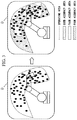
- FIG. 3 is a diagram explaining map display of the position accuracy information.
- FIG. 4 is a diagram explaining a display output by a position-accuracy output unit provided in the robot control device in FIG. 1 .
- FIG. 5 is a diagram showing example position accuracy information stored in the position-accuracy-information storage unit provided in the robot control device shown in FIG. 1 .
- FIG. 6 is a flowchart showing processing performed by the robot control device in FIG. 1 .
- the robot control device 1 includes (not shown): a CPU (Central Processing Unit); main storage devices such as a ROM (Read Only Memory) and a RAM (Random Access Memory); an auxiliary storage device such as an HDD (Hard Disk Drive); an input/output interface to which an input/output device such as a teach pendant is connected; and an external interface via which various data is exchanged with an external device such as a robot, which are connected to one another via a bus.
- the auxiliary storage device stores various programs, and, as a result of the CPU reading out programs from the auxiliary storage device into the main storage device, such as the RAM, and executing the programs, various processing is performed.
- the robot control device 1 includes, as functional blocks implemented by the CPU, a position-accuracy-information storage unit (storage unit) 11 , a position-accuracy calculation unit 12 , and a position-accuracy output unit (output unit) 13 .
- the position-accuracy-information storage unit 11 is connected to the position-accuracy calculation unit 12 and the position-accuracy output unit 13 .
- the position-accuracy calculation unit 12 is connected to a multi-joint robot 2 , the position-accuracy-information storage unit 11 , and the position-accuracy output unit 13 .
- the position-accuracy output unit 13 is connected to the position-accuracy-information storage unit 11 , the position-accuracy calculation unit 12 , and the multi-joint robot 2 .
- a teach pendant (not shown) having a display part is connected to the position-accuracy output unit 13 .
- the position-accuracy-information storage unit 11 is formed of a portion of the above-described main storage device or auxiliary storage device and is configured to store position accuracy data (position accuracy information) at respective grid points (division points) defined by dividing the overall operating area of the multi-joint robot 2 in a grid shape.
- position accuracy data is stored in the form of a position accuracy table in which the position data and the accuracy data are associated with each other.
- the position data is three-dimensional coordinate values of the respective grid points based on a robot coordinate system fixed with respect to the multi-joint robot 2 .
- the accuracy data is a value obtained by, when one grid point is assumed to be an instruction position, subtracting the instruction position from the actual end-effector position of the multi-joint robot 2 that has moved according to the instruction, that is, a difference value.
- the accuracy data is calculated with respect to all the grid points in advance and is stored in the position accuracy table.
- the actual end-effector position of the multi-joint robot 2 may be measured with a three-dimensional measuring sensor.
- the intervals between the respective grid points do not need to be equal. For example, in an area where the variation in the accuracy data is large, the grid intervals may be reduced, whereas in an area where the variation in the accuracy data is small, the grid intervals may be increased. By doing so, it is possible to obtain accurate position accuracy data while keeping the storage capacity used by the position-accuracy-information storage unit 11 low.
- the position-accuracy calculation unit 12 is configured to calculate the position accuracy at the current end-effector position of the multi-joint robot 2 on the basis of the information about the current end-effector position received from the multi-joint robot 2 and the position accuracy data stored in the position-accuracy-information storage unit 11 .
- the position accuracy at the current end-effector position may be calculated from position accuracy data at nearby grid points by using a typical known interpolation method, and for example, it may be calculated from the position accuracy data at eight grid points near the current end-effector position by linear interpolation.
- the position-accuracy output unit 13 is configured to output, to the display D (also referred to as “the display part” herein) of the teach pendant, the current position information received from the multi joint robot 2 , the position accuracy of the current position of the multi joint robot 2 calculated by the position-accuracy calculation unit 12 , and the position accuracy data of the respective grid points stored in the position-accuracy-information storage unit 11 .
- the position-accuracy output unit 13 is configured to output the operating area space of the multi-joint robot 2 such that it is divided into three areas, namely, a “good accuracy area”, a “fair accuracy area”, and a “poor accuracy area”, on the basis of the position accuracy data of the respective grid points stored in the position-accuracy-information storage unit 11 .
- a fine dot pattern area shows the “good accuracy area”
- a coarse dot pattern area shows the “fair accuracy area”
- a hatched area shows the “poor accuracy area”.
- the position-accuracy output unit 13 in this embodiment displays, on the display part of the teach pendant, the angles of the respective shafts at the current position of the multi-joint robot 2 ; an error value, an average value, and a maximum value with respect to the current position; a map of the overall operating area in which the distribution of the position accuracy data is divided into three areas according to the accuracy thereof; and a character string showing the area, among the three areas, to which the position accuracy at the current end-effector position belongs.
- a character string “good accuracy” is displayed.
- the position-accuracy calculation unit 12 calculates the position accuracy at the current end-effector position of the multi-joint robot 2 , taught by a teacher, from the position accuracy data stored in the position-accuracy-information storage unit 11 (step S 1 in FIG. 6 ).
- the position-accuracy output unit 13 outputs, to the display part of the teach pendant, the current position, the position accuracy at the current position calculated in the position-accuracy calculation unit 12 , and map display of the position accuracy data stored in the position-accuracy-information storage unit 11 (step S 2 in FIG. 6 ).
- the robot control device 1 can immediately indicate, to the teacher, the accuracy information at the current position of the multi-joint robot 2 , ease of teaching performed by the teacher improves.
- the teacher judges, based on the indicated position accuracy information, that the accuracy at the teach position is not good, he/she can teach while avoiding the position where the accuracy is not good by changing the position of the workpiece or by changing the installation position of the multi-joint robot 2 .
- the teacher can perform a calibration operation again with respect to the area for which he/she judged that the accuracy was not good.
- the second embodiment differs from the first embodiment in that the position accuracy data at a plurality of division points defined when the joint angle space of the multi joint robot 2 is divided is stored in the position-accuracy-information storage unit 11 .
- the difference from the first embodiment will be mainly described below.
- the position accuracy data stored in the position-accuracy-information storage unit 11 in this embodiment is stored in the form of a position accuracy table in which the position data of the division points in the joint angle space is associated with the accuracy data.
- the position data is expressed as the joint angles of the joint shafts J1 to J6 of the multi-joint robot 2 .
- the accuracy data is a value obtained by, when one division point is assumed to be an instruction angle, subtracting the end-effector position determined by the instruction angle from the actual end-effector position of the multi-joint robot 2 that has moved according to the instruction.
- the accuracy data is preliminarily calculated with respect to all the division points and is stored in the position accuracy table.
- the position accuracy data of the respective division points in the joint angle space formed by the joint shafts J1 to J6 is stored in the position accuracy table, elements in which the variation in the accuracy data is small may be omitted.
- the influence of the joint shafts J4 to J6 on the accuracy of the posture is small, by dividing the joint angle space formed by the joint shafts J1 to J3 into a grid shape and storing only the position accuracy data at the respective division points in the position accuracy table, it is possible to keep the storage capacity used by the position-accuracy-information storage unit 11 low.
- the position-accuracy calculation unit 12 in this embodiment is configured to calculate the accuracy information at the current position of the multi-joint robot 2 based on the current joint angle information received from the multi-joint robot 2 and the position accuracy data stored in the position-accuracy-information storage unit 11 .
- the accuracy information at the current position can be calculated from the position accuracy data at nearby division points by using a typical known interpolation method.
- the position accuracy data stored in the position-accuracy-information storage unit 11 is based on the joint angle space, and because it is possible to show a teacher the accuracy information at the current position of the multi-joint robot 2 calculated therefrom, the teacher can teach while avoiding the vicinity of the singular point where the accuracy decreases.
- the accuracy data in the position accuracy table is stored in the form of the respective X, Y, and Z components, the form is not limited thereto, and the accuracy data may be stored in another form.
- the output destination to which the position-accuracy output unit 13 outputs the position accuracy is the display part of the teach pendant, the output destination is not limited thereto and may be another external output device that can be connected to the robot control device 1 .
- a first aspect of the present invention is directed to a robot control device including: a storage unit that stores position accuracy information at a plurality of division points defined when an operating area space of a multi joint robot is divided into a plurality of areas in a grid shape; a position-accuracy calculation unit that calculates, based on the position accuracy information and the current end-effector position of the multi joint robot, position accuracy at the end-effector position; and an output unit that outputs the calculated position accuracy to an outside.
- the position accuracy at the end-effector position is calculated by the position-accuracy calculation unit based on the position accuracy information at a plurality of division points preliminarily stored in the storage unit and the current end-effector position of the multi-joint robot. Then, the calculated position accuracy is output to the outside by the output unit.
- this configuration enables the position accuracy at the current end-effector position of the multi-joint robot to be immediately indicated to a teacher, it is possible to improve the ease of teaching performed by the teacher.
- the teacher judges, based on the indicated position accuracy information, that the accuracy at the teach position is not good, the teacher can teach while avoiding the position where the accuracy is not good by changing the position of the workpiece or by changing the installation position of the multi joint robot. Furthermore, the teacher can perform a calibration operation again with respect to the area for which he/she judged that the accuracy was not good.
- the output unit may be configured to output, as a form of a map, the distribution of a plurality of items of the position accuracy information stored in the storage unit.
- This configuration enables the teacher to obtain an overview of the distribution of the position accuracy information in the operating area space of the multi-joint robot. Hence, it is possible to further improve ease of teaching performed by the teacher.
- a second aspect of the present invention is directed to a robot control device including: a storage unit that stores position accuracy information at a plurality of division points defined when a joint angle space of a multi-joint robot is divided; a position-accuracy calculation unit that calculates, based on the position accuracy information and the current joint angle of the multi-joint robot, position accuracy at this joint angle; and an output unit that outputs the calculated position accuracy to an outside.
- the position accuracy at this end-effector position is calculated by the position-accuracy calculation unit. Then, the calculated position accuracy is output to the outside by the output unit.
- the teacher can teach while avoiding the vicinity of the singular point where the accuracy decreases. As a result, it is possible to improve the ease of teaching performed by the teacher.
- the position accuracy information may include a difference value between the actual position of the multi-joint robot that has been measured in advance and an instructed position.
- the present invention provides an advantage in that it is possible to improve the ease of teaching when teaching a multi-joint robot.
Landscapes
- Engineering & Computer Science (AREA)
- Robotics (AREA)
- Mechanical Engineering (AREA)
- Automation & Control Theory (AREA)
- Physics & Mathematics (AREA)
- Artificial Intelligence (AREA)
- Evolutionary Computation (AREA)
- Fuzzy Systems (AREA)
- Mathematical Physics (AREA)
- Software Systems (AREA)
- Numerical Control (AREA)
- Manipulator (AREA)
Applications Claiming Priority (3)
| Application Number | Priority Date | Filing Date | Title |
|---|---|---|---|
| JP2017-006071 | 2017-01-17 | ||
| JP2017006071A JP6490112B2 (ja) | 2017-01-17 | 2017-01-17 | ロボット制御装置 |
| JPJP2017-006071 | 2017-01-17 |
Publications (2)
| Publication Number | Publication Date |
|---|---|
| US20180200886A1 US20180200886A1 (en) | 2018-07-19 |
| US10953540B2 true US10953540B2 (en) | 2021-03-23 |
Family
ID=62716591
Family Applications (1)
| Application Number | Title | Priority Date | Filing Date |
|---|---|---|---|
| US15/867,339 Active 2038-10-16 US10953540B2 (en) | 2017-01-17 | 2018-01-10 | Robot control device |
Country Status (4)
| Country | Link |
|---|---|
| US (1) | US10953540B2 (zh) |
| JP (1) | JP6490112B2 (zh) |
| CN (1) | CN108326876B (zh) |
| DE (1) | DE102018200240B4 (zh) |
Families Citing this family (8)
| Publication number | Priority date | Publication date | Assignee | Title |
|---|---|---|---|---|
| CN108466290B (zh) * | 2018-03-09 | 2021-02-19 | 苏州灵猴机器人有限公司 | 机器人辅助作业系统及其辅助作业方法 |
| JP7035727B2 (ja) * | 2018-03-30 | 2022-03-15 | 日本電産株式会社 | キャリブレーション精度の評価方法及び評価装置 |
| JP7161753B2 (ja) * | 2018-10-24 | 2022-10-27 | 国立大学法人広島大学 | ロボットの運動精度測定方法及び位置補正方法 |
| JP7305951B2 (ja) * | 2018-12-14 | 2023-07-11 | ニデック株式会社 | キャリブレーション装置及びキャリブレーション方法 |
| CN111376242B (zh) * | 2018-12-29 | 2022-11-01 | 苏州灵猴机器人有限公司 | 基于模式控制的机器人拖动示教方法和系统 |
| WO2020211914A1 (en) * | 2019-04-17 | 2020-10-22 | Universal Robots A/S | Method of controlling a robot arm based on adaptive friction |
| CN113290570B (zh) * | 2020-07-20 | 2024-04-19 | 阿里巴巴集团控股有限公司 | 夹持装置、数据中心运维机器人及装配机器人 |
| JPWO2023013740A1 (zh) * | 2021-08-04 | 2023-02-09 |
Citations (12)
| Publication number | Priority date | Publication date | Assignee | Title |
|---|---|---|---|---|
| JPH0683427A (ja) | 1992-09-04 | 1994-03-25 | Japan Atom Energy Res Inst | 柔軟マニピュレータの作業点位置制御システム |
| JPH08272414A (ja) | 1995-03-29 | 1996-10-18 | Fanuc Ltd | ロボットとハンドカメラを用いた視覚センサのキャリブレーション方法 |
| JPH09237112A (ja) | 1996-02-29 | 1997-09-09 | Toyoda Mach Works Ltd | 誤差補正機能を備えた工作機械 |
| JP2003141511A (ja) | 2001-11-07 | 2003-05-16 | Kawasaki Heavy Ind Ltd | 3次元形状認識方法、装置およびプログラム |
| US20080201015A1 (en) * | 2005-02-28 | 2008-08-21 | Torgny Brogardh | System for Calibration of an Industrial Robot and a Method Thereof |
| JP2009148850A (ja) | 2007-12-20 | 2009-07-09 | Denso Wave Inc | ロボットの動作制御装置及びその動作制御方法 |
| EP2522952A2 (en) | 2011-05-11 | 2012-11-14 | Mitutoyo Corporation | Method for generating error image and system for generating error image |
| EP2551069A2 (en) | 2011-07-26 | 2013-01-30 | Kabushiki Kaisha Yaskawa Denki | Robot and method for manufacturing the same |
| JP2014065100A (ja) | 2012-09-25 | 2014-04-17 | Denso Wave Inc | ロボットシステム、及びロボットのティーチング方法 |
| JP2014135068A (ja) | 2014-02-27 | 2014-07-24 | Makino Milling Mach Co Ltd | エラーマップ作成方法及び装置並びにエラーマップ作成機能を有した数値制御工作機械 |
| US20150258690A1 (en) * | 2014-03-12 | 2015-09-17 | Fanuc Corporation | Robot control device detecting contact with external environment |
| US20150363907A1 (en) * | 2014-06-16 | 2015-12-17 | Canon Kabushiki Kaisha | Image processing apparatus and image processing method |
Family Cites Families (8)
| Publication number | Priority date | Publication date | Assignee | Title |
|---|---|---|---|---|
| JPH053427A (ja) | 1991-06-25 | 1993-01-08 | Matsushita Electric Works Ltd | 遅延型フオトモスリレー |
| US6535794B1 (en) * | 1993-02-23 | 2003-03-18 | Faro Technologoies Inc. | Method of generating an error map for calibration of a robot or multi-axis machining center |
| JP3665353B2 (ja) * | 1993-09-14 | 2005-06-29 | ファナック株式会社 | ロボットの教示位置データの3次元位置補正量取得方法及びロボットシステム |
| JPH10240323A (ja) * | 1997-02-25 | 1998-09-11 | Hitachi Ltd | 移動ロボットの異常動作防止方法 |
| JP5856837B2 (ja) * | 2011-12-22 | 2016-02-10 | 川崎重工業株式会社 | ロボット教示点作成方法およびロボットシステム |
| CN102581445B (zh) * | 2012-02-08 | 2014-08-13 | 中国科学院自动化研究所 | 机器人的视觉实时纠偏系统和纠偏方法 |
| CN203242211U (zh) * | 2013-01-09 | 2013-10-16 | 北京石油化工学院 | 机器人焊接3d辅助示教系统 |
| CN104175031B (zh) * | 2014-08-20 | 2016-02-17 | 北京工业大学 | 一种具有自主纠偏能力的焊接机器人系统进行焊接的方法 |
-
2017
- 2017-01-17 JP JP2017006071A patent/JP6490112B2/ja active Active
-
2018
- 2018-01-04 CN CN201810008638.8A patent/CN108326876B/zh active Active
- 2018-01-09 DE DE102018200240.1A patent/DE102018200240B4/de active Active
- 2018-01-10 US US15/867,339 patent/US10953540B2/en active Active
Patent Citations (19)
| Publication number | Priority date | Publication date | Assignee | Title |
|---|---|---|---|---|
| JPH0683427A (ja) | 1992-09-04 | 1994-03-25 | Japan Atom Energy Res Inst | 柔軟マニピュレータの作業点位置制御システム |
| JPH08272414A (ja) | 1995-03-29 | 1996-10-18 | Fanuc Ltd | ロボットとハンドカメラを用いた視覚センサのキャリブレーション方法 |
| JPH09237112A (ja) | 1996-02-29 | 1997-09-09 | Toyoda Mach Works Ltd | 誤差補正機能を備えた工作機械 |
| JP2003141511A (ja) | 2001-11-07 | 2003-05-16 | Kawasaki Heavy Ind Ltd | 3次元形状認識方法、装置およびプログラム |
| US20080201015A1 (en) * | 2005-02-28 | 2008-08-21 | Torgny Brogardh | System for Calibration of an Industrial Robot and a Method Thereof |
| JP2009148850A (ja) | 2007-12-20 | 2009-07-09 | Denso Wave Inc | ロボットの動作制御装置及びその動作制御方法 |
| JP2012237620A (ja) | 2011-05-11 | 2012-12-06 | Mitsutoyo Corp | 誤差画像生成方法 |
| US20120290260A1 (en) * | 2011-05-11 | 2012-11-15 | Mitutoyo Corporation | Method for generating error image and program for generating error image |
| EP2522952A2 (en) | 2011-05-11 | 2012-11-14 | Mitutoyo Corporation | Method for generating error image and system for generating error image |
| US9188435B2 (en) | 2011-05-11 | 2015-11-17 | Mitutoyo Corporation | Method for generating error image and program for generating error image |
| EP2551069A2 (en) | 2011-07-26 | 2013-01-30 | Kabushiki Kaisha Yaskawa Denki | Robot and method for manufacturing the same |
| US20130025399A1 (en) * | 2011-07-26 | 2013-01-31 | Kabishiki Kaisha Yaskawa Denki | Robot and method for manufacturing the same |
| JP2013027939A (ja) | 2011-07-26 | 2013-02-07 | Yaskawa Electric Corp | ロボットおよびロボットの製造方法 |
| JP2014065100A (ja) | 2012-09-25 | 2014-04-17 | Denso Wave Inc | ロボットシステム、及びロボットのティーチング方法 |
| JP2014135068A (ja) | 2014-02-27 | 2014-07-24 | Makino Milling Mach Co Ltd | エラーマップ作成方法及び装置並びにエラーマップ作成機能を有した数値制御工作機械 |
| US20150258690A1 (en) * | 2014-03-12 | 2015-09-17 | Fanuc Corporation | Robot control device detecting contact with external environment |
| JP2015171747A (ja) | 2014-03-12 | 2015-10-01 | ファナック株式会社 | 外部環境との接触を検知するロボット制御装置 |
| US20150363907A1 (en) * | 2014-06-16 | 2015-12-17 | Canon Kabushiki Kaisha | Image processing apparatus and image processing method |
| JP2016002214A (ja) | 2014-06-16 | 2016-01-12 | キヤノン株式会社 | 画像処理装置、画像処理方法およびプログラム |
Non-Patent Citations (3)
| Title |
|---|
| German Office Action dated Feb. 19, 2020, for German Patent Application No. 10 2018 200 240.1. |
| Japanese Office Action dated Jul. 17, 2018, for Japanese Patent Application No. 2017-006071. |
| NPL:JP2014_135068_translation (Year: 2014). * |
Also Published As
| Publication number | Publication date |
|---|---|
| CN108326876A (zh) | 2018-07-27 |
| US20180200886A1 (en) | 2018-07-19 |
| JP2018114578A (ja) | 2018-07-26 |
| DE102018200240B4 (de) | 2020-09-10 |
| CN108326876B (zh) | 2019-09-06 |
| DE102018200240A1 (de) | 2018-07-19 |
| JP6490112B2 (ja) | 2019-03-27 |
Similar Documents
| Publication | Publication Date | Title |
|---|---|---|
| US10953540B2 (en) | Robot control device | |
| US10661440B2 (en) | Robot teaching device for warning or correcting positional deviation of teaching points or teaching line | |
| EP2016370B1 (en) | Differential calibration | |
| US10596706B2 (en) | Mechanism-parameter-calibration method for robotic arm system | |
| Guo et al. | A multilevel calibration technique for an industrial robot with parallelogram mechanism | |
| JP5618066B2 (ja) | 力制御ロボットのキャリブレーション装置と方法 | |
| US20120215334A1 (en) | Tool path generation method and device | |
| US20110029131A1 (en) | Apparatus and method for measuring tool center point position of robot | |
| CN105855672B (zh) | 基于示教机器人的空间圆弧插补焊接方法 | |
| JPH04233602A (ja) | ロボットのたわみ補正方法及びたわみ認識方法 | |
| JP2012176465A (ja) | トルクセンサ校正装置、校正方法、及びプログラム | |
| US10507585B2 (en) | Robot system that displays speed | |
| CN111531533A (zh) | 一种六维力传感器的零点校正及重力补偿方法 | |
| CN116901081B (zh) | 机器人dh参数标定方法、装置、电子设备及存储介质 | |
| JPS6190205A (ja) | ロボツトの絶対位置決め誤差補償方法 | |
| JP2002018750A (ja) | ロボットのキャリブレーション方法及び装置 | |
| CN113146630A (zh) | 工业机器人铣削加工误差补偿方法、系统、装置及介质 | |
| US20200171666A1 (en) | Mechanism-parameter-calibration method for robotic arm system | |
| CN112621739A (zh) | 机器人及其路径插值规划命令产生系统 | |
| JP2002351531A (ja) | 教示データ補正方法および補正装置 | |
| JP2002215211A (ja) | 数値制御装置 | |
| WO2024105847A1 (ja) | 制御装置、3次元位置計測システム、及びプログラム | |
| JP2001018182A (ja) | ロボット機構較正演算方法及びシステム | |
| CN114179088B (zh) | 机器人负载补偿实现方法、装置及机器人 | |
| JP2567372B2 (ja) | ロボット座標補正処理方法 |
Legal Events
| Date | Code | Title | Description |
|---|---|---|---|
| FEPP | Fee payment procedure |
Free format text: ENTITY STATUS SET TO UNDISCOUNTED (ORIGINAL EVENT CODE: BIG.); ENTITY STATUS OF PATENT OWNER: LARGE ENTITY |
|
| AS | Assignment |
Owner name: FANUC CORPORATION, JAPAN Free format text: ASSIGNMENT OF ASSIGNORS INTEREST;ASSIGNORS:WANG, YUELAI;ARITA, SOICHI;REEL/FRAME:044603/0326 Effective date: 20170919 |
|
| STPP | Information on status: patent application and granting procedure in general |
Free format text: DOCKETED NEW CASE - READY FOR EXAMINATION |
|
| AS | Assignment |
Owner name: FANUC CORPORATION, JAPAN Free format text: CORRECTIVE ASSIGNMENT TO CORRECT THE FILING DATE INSIDE THE ASSIGNMENT DOCUMENT PREVIOUSLY RECORDED AT REEL: 044603 FRAME: 0326. ASSIGNOR(S) HEREBY CONFIRMS THE ASSIGNMENT;ASSIGNORS:WANG, YUELAI;ARITA, SOICHI;REEL/FRAME:046580/0424 Effective date: 20170919 |
|
| STPP | Information on status: patent application and granting procedure in general |
Free format text: NON FINAL ACTION MAILED |
|
| STPP | Information on status: patent application and granting procedure in general |
Free format text: FINAL REJECTION MAILED |
|
| STPP | Information on status: patent application and granting procedure in general |
Free format text: ADVISORY ACTION MAILED |
|
| STPP | Information on status: patent application and granting procedure in general |
Free format text: DOCKETED NEW CASE - READY FOR EXAMINATION |
|
| STPP | Information on status: patent application and granting procedure in general |
Free format text: NOTICE OF ALLOWANCE MAILED -- APPLICATION RECEIVED IN OFFICE OF PUBLICATIONS |
|
| STCF | Information on status: patent grant |
Free format text: PATENTED CASE |
|
| MAFP | Maintenance fee payment |
Free format text: PAYMENT OF MAINTENANCE FEE, 4TH YEAR, LARGE ENTITY (ORIGINAL EVENT CODE: M1551); ENTITY STATUS OF PATENT OWNER: LARGE ENTITY Year of fee payment: 4 |