US1094271A - Device for stacking mail-matter. - Google Patents
Device for stacking mail-matter. Download PDFInfo
- Publication number
- US1094271A US1094271A US79236713A US1913792367A US1094271A US 1094271 A US1094271 A US 1094271A US 79236713 A US79236713 A US 79236713A US 1913792367 A US1913792367 A US 1913792367A US 1094271 A US1094271 A US 1094271A
- Authority
- US
- United States
- Prior art keywords
- base
- bracket
- arm
- standard
- matter
- Prior art date
- Legal status (The legal status is an assumption and is not a legal conclusion. Google has not performed a legal analysis and makes no representation as to the accuracy of the status listed.)
- Expired - Lifetime
Links
- 238000010276 construction Methods 0.000 description 2
- 239000011435 rock Substances 0.000 description 2
- 230000000295 complement effect Effects 0.000 description 1
- 238000003780 insertion Methods 0.000 description 1
- 230000037431 insertion Effects 0.000 description 1
Images
Classifications
-
- B—PERFORMING OPERATIONS; TRANSPORTING
- B42—BOOKBINDING; ALBUMS; FILES; SPECIAL PRINTED MATTER
- B42F—SHEETS TEMPORARILY ATTACHED TOGETHER; FILING APPLIANCES; FILE CARDS; INDEXING
- B42F17/00—Card-filing arrangements, e.g. card indexes or catalogues or filing cabinets
- B42F17/02—Card-filing arrangements, e.g. card indexes or catalogues or filing cabinets in which the cards are stored substantially at right angles to the bottom of their containers
Definitions
- My invention relates to a device for use in stacking letters, circulars, newspapers and other mail matter ready for tying in bundles.
- Figure 1 is a perspective view of a device embodying my invention
- Fig. 2 is a plan view
- Fig. 3 is a side elevation with parts in knockdown form
- Fig. 4 is a detail cross section on a larger scale, hereinafter to be referred to
- Fig. 5 is a perspective view of a bracket for mounting the presser arm forming a part of the device.
- any suitable base 10 is provided, here shown as a rectangular slab or board.
- On the base at one side edge is provided one, two or more upright elements constituting back stops against which the articles of mail matter may be placed to aline the same.
- the stops in the present instance are in the form of standards 11, 12, 13, having inturned ends 11*, 12 13 which are threaded or otherwise snugly held in corresponding recesses in the base, but not sufliciently tight to prevent the standards from being folded downward to the position shown in Fig. 3, or into upright position as in Figs. 1 and 2.
- a front stop 14 is provided in the form of a standard, the foot 14 of which is in turned at a right angle, and enters a corresponding transverse hole in the base 10, (see Fig. 4).
- the under side of the foot 14 is flattened as at 14 Fig. 4, there being a shoulder, as indicated at 14 at the inner end of such flattened portion.
- the said foot fits slidably, but friction tight in the base 10, and the fiat side of the foot, when the stand- Specification of Letters Patent.
- the spring serving to normally maintain the standard upright.
- the standard may be adj usted laterally to an outer or inner position for varying the width of the space between the back stops and the front stop 14.
- the stop 14 may be rocked to disengage the flat side 14 from the spring 15 and permit the standard to be entirely withdrawn if desired.
- the inner end of the foot 14 is pointed, as at 14, to facilitate the entrance of the foot in the base.
- Means may be provided for holding one or all of the stops in upright position, said means being shown in Figs. 1 and 2 in connection with the standard 11, and may consist of a hook 17 pivoted to the base in position to be turned into engagement with the standard, as shown in Fig.- 1, the hook having a lug 17 a or like finger hold.
- the bracket is designed to be passed onto the standard 11 by first so disposing the bracket that its lower notch 23 will register with and pass the projection 11. The bracket is then turned on its axis to bring the upper notch 23 in register with the projection 11*, to permit the upper bent end 21 of the bracket to pass the said projection; thus the bracket cannot accidentally become detached.
- a re'tractile spring 24 is connected at one end with the bracket 20 and at the other end with the clutch plate 25, loose on the arm 18.
- the spring normally tends to press the arm downwardly in the direction of the base, and thereby exert a pressure on the mail matter, the arm being adapted to be rocked on its pivot 19 against the tension of the spring for the insertion of additional mail matter, and being adapted to be swung laterally by reason of the bracket 20 turning on the standard 11, whereby to withdraw the bent end 18 from beneath any mail matter placed on top of said bent end.
- the clutch plate 25 is adapted to engage one of the series of holes 18 in the presser arm 18, whereby to vary the tension of the spring 241-.
- the several stops 11, 12, 13, 14, can be folded downwardly alongside the edges of the base 10, and the bracket 20 with its presser arm 18, detached from the stop 11 or equivalent support and laid on top of the base 10, as in Fig. 3.
- the catch 17 is omitted.
- a groove 10 may be formed in the upper side of the base 10 for the user to pass a finger beneath the accumulated mail mat ter for lifting the same. Or a cord may be laid in said groove and the ends brought up over the bundle of letters or the like to be tied.
- a base In a device of the character described, a base, a presser arm, and an element on the side of the base on which said arm is mounted to swing to a position over the base, or away from the latter, said arm having the free end thereof bent inwardly.
- a base a standard
- a bracket mounted to swing and to slide on the standard
- a presser arm pivoted to rock vertically on the bracket
- a spring connected with the bracket and with the arm to exert a downward pull on the arm.
- a base a standard at the side'thereof, a bracket mounted to slide on the standard and to swing laterally thereon, a presser arm pivoted to rock vertically on the bracket, a clutch plate loose on the arm, said arm having a series of notches to engage the clutch plate, and a spring connected at one end with said plate and at the opposite end with the bracket.
Landscapes
- Purses, Travelling Bags, Baskets, Or Suitcases (AREA)
Description
v E. P. P. THOMPSON. DEVICE FOR STAOKING MAIL MATTER.
APPLICATION FILED SEPT. 29, 1913.
1,094,271 Patented Apr. 21, 1914.
ATTORNEYS 4 WITNE88E8 LOLL'MHIA I'LANOGRAPII couwasmxcTox 1).;
EARL I. F. THOMPSON,
OF TROY, TEXAS.
DEVICE FOR STACKING MAIL-MATTER.
To all whom it may concern:
Be it known that LEARL P. F. THOMPSON, a citizen of the United States, and a resident of Troy, in the county of Bell and State of Texas, have invented a new and Improved Device for Stacking Mail-Matter, of which the following is a full, clear, and exact description,
My invention relates to a device for use in stacking letters, circulars, newspapers and other mail matter ready for tying in bundles.
It is a design of my invention to provide an article of the indicated character, simple in construction, eflicient in use, and capable of being folded into small compass when not required for use.
The invention will be particularly eX- plained in the specific description following.
Reference is to be had to the accompanying drawings forming a part of'this specification, in which similar characters of reference indicate corresponding parts in all the views.
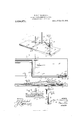
Figure 1 is a perspective view of a device embodying my invention; Fig. 2 is a plan view; Fig. 3 is a side elevation with parts in knockdown form; Fig. 4 is a detail cross section on a larger scale, hereinafter to be referred to; and Fig. 5 is a perspective view of a bracket for mounting the presser arm forming a part of the device.
In constructing the improved mail-stacking device any suitable base 10 is provided, here shown as a rectangular slab or board. On the base at one side edge is provided one, two or more upright elements constituting back stops against which the articles of mail matter may be placed to aline the same. The stops in the present instance are in the form of standards 11, 12, 13, having inturned ends 11*, 12 13 which are threaded or otherwise snugly held in corresponding recesses in the base, but not sufliciently tight to prevent the standards from being folded downward to the position shown in Fig. 3, or into upright position as in Figs. 1 and 2. At the opposite side a front stop 14 is provided in the form of a standard, the foot 14 of which is in turned at a right angle, and enters a corresponding transverse hole in the base 10, (see Fig. 4). The under side of the foot 14 is flattened as at 14 Fig. 4, there being a shoulder, as indicated at 14 at the inner end of such flattened portion. The said foot fits slidably, but friction tight in the base 10, and the fiat side of the foot, when the stand- Specification of Letters Patent.
Application filed September 29, 1913.
Patented Apr. 21, 1914.
Serial No. 792,367.
ard is upright, is pressed against by a plate spring 15, secured by a screw 16 or the like in a recess 10 in the under side of the base,
the spring serving to normally maintain the standard upright. The standard may be adj usted laterally to an outer or inner position for varying the width of the space between the back stops and the front stop 14. The stop 14 may be rocked to disengage the flat side 14 from the spring 15 and permit the standard to be entirely withdrawn if desired. The inner end of the foot 14 is pointed, as at 14, to facilitate the entrance of the foot in the base. Means may be provided for holding one or all of the stops in upright position, said means being shown in Figs. 1 and 2 in connection with the standard 11, and may consist of a hook 17 pivoted to the base in position to be turned into engagement with the standard, as shown in Fig.- 1, the hook having a lug 17 a or like finger hold.
011 the standard 11 or other equivalent up right element, I mount a presser arm 18, having its free end inturned as at 18 to overlie the base. The said arm is pivoted to a bracket 20, as by a rivet or pin 19 passing through said arm and through a hole 20 in the bracket. The upper and lower ends of the bracket are bent at right angles and formed with holes 22 to permit the bracket to slidably fit the standard 11. At a side of each hole 22, and complementary thereto, is
a notch 23, and these notches, as will be seen from Fig. 5, are out of register, being in dilferent angular positions. On the upper end of the standard 11, at one side, is a projection 11 corresponding approximately with the recesses 23. The bracket is designed to be passed onto the standard 11 by first so disposing the bracket that its lower notch 23 will register with and pass the projection 11. The bracket is then turned on its axis to bring the upper notch 23 in register with the projection 11*, to permit the upper bent end 21 of the bracket to pass the said projection; thus the bracket cannot accidentally become detached.
The described construction permits the arm 18 to he slid vertically on the standard 11, and to swing laterally thereon, so that the inturned end 18 will overlie the accu mulating mail matter, shown conventionally by dotted lines in Fig. 1 and indicated by the letter a. A re'tractile spring 24 is connected at one end with the bracket 20 and at the other end with the clutch plate 25, loose on the arm 18. The spring normally tends to press the arm downwardly in the direction of the base, and thereby exert a pressure on the mail matter, the arm being adapted to be rocked on its pivot 19 against the tension of the spring for the insertion of additional mail matter, and being adapted to be swung laterally by reason of the bracket 20 turning on the standard 11, whereby to withdraw the bent end 18 from beneath any mail matter placed on top of said bent end. The clutch plate 25 is adapted to engage one of the series of holes 18 in the presser arm 18, whereby to vary the tension of the spring 241-.
When the device is not in use the several stops 11, 12, 13, 14, can be folded downwardly alongside the edges of the base 10, and the bracket 20 with its presser arm 18, detached from the stop 11 or equivalent support and laid on top of the base 10, as in Fig. 3. In Fig. 3 the catch 17 is omitted.
A groove 10 may be formed in the upper side of the base 10 for the user to pass a finger beneath the accumulated mail mat ter for lifting the same. Or a cord may be laid in said groove and the ends brought up over the bundle of letters or the like to be tied.
Having thus described my invention, I claim as new and desire to secure by Letters Patent:
1. A device of the character described,
comprising a base, a stop at one side of the.
base, and a stop at the opposite side, one of said stops having a foot slidable' in the base and adapted to turn therein.
2. A device of the character described,
comprising a base, .a stop at one side of the base, and a stop at the opposite side one of said stops having a foot slidable in the base and adapted to turn therein, the said foot having a flattened side, and there being a plate spring on the base pressing on said foot, the foot furthermore having a shoulder at the inner end of the flattened portion.
3. In a device of the character described, a base, a presser arm, and an element on the side of the base on which said arm is mounted to swing to a position over the base, or away from the latter, said arm having the free end thereof bent inwardly.
4. In a device of the character described, a base, a standard, a bracket mounted to swing and to slide on the standard, a presser arm pivoted to rock vertically on the bracket, and a spring connected with the bracket and with the arm to exert a downward pull on the arm.
5. In a device of the character described, a base, a standard at the side'thereof, a bracket mounted to slide on the standard and to swing laterally thereon, a presser arm pivoted to rock vertically on the bracket, a clutch plate loose on the arm, said arm having a series of notches to engage the clutch plate, and a spring connected at one end with said plate and at the opposite end with the bracket.
In testimony whereof I have signed my name to this specification in the presence of two subscribing witnesses.
EARL P. r. THOMPSON. V
Witnesses:
C. A. Nonwoon, L. M. HA'lCI-IER.
Copies of tl'iis patent may be obtained for five cents each, by addressing the Commissioner of Patents,
- Washington, D. G.
Priority Applications (1)
| Application Number | Priority Date | Filing Date | Title |
|---|---|---|---|
| US79236713A US1094271A (en) | 1913-09-29 | 1913-09-29 | Device for stacking mail-matter. |
Applications Claiming Priority (1)
| Application Number | Priority Date | Filing Date | Title |
|---|---|---|---|
| US79236713A US1094271A (en) | 1913-09-29 | 1913-09-29 | Device for stacking mail-matter. |
Publications (1)
| Publication Number | Publication Date |
|---|---|
| US1094271A true US1094271A (en) | 1914-04-21 |
Family
ID=3162480
Family Applications (1)
| Application Number | Title | Priority Date | Filing Date |
|---|---|---|---|
| US79236713A Expired - Lifetime US1094271A (en) | 1913-09-29 | 1913-09-29 | Device for stacking mail-matter. |
Country Status (1)
| Country | Link |
|---|---|
| US (1) | US1094271A (en) |
-
1913
- 1913-09-29 US US79236713A patent/US1094271A/en not_active Expired - Lifetime
Similar Documents
| Publication | Publication Date | Title |
|---|---|---|
| US1094271A (en) | Device for stacking mail-matter. | |
| US263685A (en) | Chestee c | |
| US576453A (en) | Display-stand | |
| US721996A (en) | Paper-bag holder. | |
| US484268A (en) | westeup | |
| US938621A (en) | Binder. | |
| US1101780A (en) | Loose-leaf binder. | |
| US1019348A (en) | Paper-clip. | |
| US272263A (en) | Island | |
| US538605A (en) | Aboh- file | |
| US355207A (en) | Joseph agustus eeinfeld | |
| US196306A (en) | Improvement in temporary binders | |
| US1069543A (en) | Combined tie holder and pressing device. | |
| US934424A (en) | Christmas-tree holder. | |
| US1154260A (en) | Combined paper-weight and bill-file. | |
| US948502A (en) | Loose-leaf binder. | |
| US802403A (en) | Temporary binder. | |
| US1109053A (en) | Bill-file. | |
| US275294A (en) | Mop-head | |
| US804743A (en) | Writing-tablet. | |
| US268335A (en) | Gustav wicke | |
| US199998A (en) | Improvement in temporary binders | |
| US303561A (en) | Paper-bag holder | |
| US450747A (en) | Bag-holder | |
| US751824A (en) | Andeeas zolles |