US10879572B2 - Power supply device and vehicle provided with same - Google Patents
Power supply device and vehicle provided with same Download PDFInfo
- Publication number
- US10879572B2 US10879572B2 US15/540,376 US201515540376A US10879572B2 US 10879572 B2 US10879572 B2 US 10879572B2 US 201515540376 A US201515540376 A US 201515540376A US 10879572 B2 US10879572 B2 US 10879572B2
- Authority
- US
- United States
- Prior art keywords
- battery case
- frame
- disposed
- power supply
- supply device
- Prior art date
- Legal status (The legal status is an assumption and is not a legal conclusion. Google has not performed a legal analysis and makes no representation as to the accuracy of the status listed.)
- Active, expires
Links
Images


Classifications
-
- H—ELECTRICITY
- H01—ELECTRIC ELEMENTS
- H01M—PROCESSES OR MEANS, e.g. BATTERIES, FOR THE DIRECT CONVERSION OF CHEMICAL ENERGY INTO ELECTRICAL ENERGY
- H01M10/00—Secondary cells; Manufacture thereof
- H01M10/60—Heating or cooling; Temperature control
- H01M10/65—Means for temperature control structurally associated with the cells
- H01M10/656—Means for temperature control structurally associated with the cells characterised by the type of heat-exchange fluid
- H01M10/6561—Gases
- H01M10/6563—Gases with forced flow, e.g. by blowers
-
- B—PERFORMING OPERATIONS; TRANSPORTING
- B60—VEHICLES IN GENERAL
- B60L—PROPULSION OF ELECTRICALLY-PROPELLED VEHICLES; SUPPLYING ELECTRIC POWER FOR AUXILIARY EQUIPMENT OF ELECTRICALLY-PROPELLED VEHICLES; ELECTRODYNAMIC BRAKE SYSTEMS FOR VEHICLES IN GENERAL; MAGNETIC SUSPENSION OR LEVITATION FOR VEHICLES; MONITORING OPERATING VARIABLES OF ELECTRICALLY-PROPELLED VEHICLES; ELECTRIC SAFETY DEVICES FOR ELECTRICALLY-PROPELLED VEHICLES
- B60L50/00—Electric propulsion with power supplied within the vehicle
- B60L50/50—Electric propulsion with power supplied within the vehicle using propulsion power supplied by batteries or fuel cells
- B60L50/60—Electric propulsion with power supplied within the vehicle using propulsion power supplied by batteries or fuel cells using power supplied by batteries
- B60L50/64—Constructional details of batteries specially adapted for electric vehicles
-
- H—ELECTRICITY
- H01—ELECTRIC ELEMENTS
- H01M—PROCESSES OR MEANS, e.g. BATTERIES, FOR THE DIRECT CONVERSION OF CHEMICAL ENERGY INTO ELECTRICAL ENERGY
- H01M10/00—Secondary cells; Manufacture thereof
- H01M10/42—Methods or arrangements for servicing or maintenance of secondary cells or secondary half-cells
- H01M10/425—Structural combination with electronic components, e.g. electronic circuits integrated to the outside of the casing
- H01M10/4257—Smart batteries, e.g. electronic circuits inside the housing of the cells or batteries
-
- H—ELECTRICITY
- H01—ELECTRIC ELEMENTS
- H01M—PROCESSES OR MEANS, e.g. BATTERIES, FOR THE DIRECT CONVERSION OF CHEMICAL ENERGY INTO ELECTRICAL ENERGY
- H01M10/00—Secondary cells; Manufacture thereof
- H01M10/60—Heating or cooling; Temperature control
- H01M10/61—Types of temperature control
- H01M10/613—Cooling or keeping cold
-
- H—ELECTRICITY
- H01—ELECTRIC ELEMENTS
- H01M—PROCESSES OR MEANS, e.g. BATTERIES, FOR THE DIRECT CONVERSION OF CHEMICAL ENERGY INTO ELECTRICAL ENERGY
- H01M10/00—Secondary cells; Manufacture thereof
- H01M10/60—Heating or cooling; Temperature control
- H01M10/62—Heating or cooling; Temperature control specially adapted for specific applications
- H01M10/625—Vehicles
-
- H—ELECTRICITY
- H01—ELECTRIC ELEMENTS
- H01M—PROCESSES OR MEANS, e.g. BATTERIES, FOR THE DIRECT CONVERSION OF CHEMICAL ENERGY INTO ELECTRICAL ENERGY
- H01M10/00—Secondary cells; Manufacture thereof
- H01M10/60—Heating or cooling; Temperature control
- H01M10/64—Heating or cooling; Temperature control characterised by the shape of the cells
- H01M10/647—Prismatic or flat cells, e.g. pouch cells
-
- H—ELECTRICITY
- H01—ELECTRIC ELEMENTS
- H01M—PROCESSES OR MEANS, e.g. BATTERIES, FOR THE DIRECT CONVERSION OF CHEMICAL ENERGY INTO ELECTRICAL ENERGY
- H01M10/00—Secondary cells; Manufacture thereof
- H01M10/60—Heating or cooling; Temperature control
- H01M10/65—Means for temperature control structurally associated with the cells
- H01M10/655—Solid structures for heat exchange or heat conduction
- H01M10/6556—Solid parts with flow channel passages or pipes for heat exchange
- H01M10/6557—Solid parts with flow channel passages or pipes for heat exchange arranged between the cells
-
- H—ELECTRICITY
- H01—ELECTRIC ELEMENTS
- H01M—PROCESSES OR MEANS, e.g. BATTERIES, FOR THE DIRECT CONVERSION OF CHEMICAL ENERGY INTO ELECTRICAL ENERGY
- H01M10/00—Secondary cells; Manufacture thereof
- H01M10/60—Heating or cooling; Temperature control
- H01M10/66—Heat-exchange relationships between the cells and other systems, e.g. central heating systems or fuel cells
- H01M10/667—Heat-exchange relationships between the cells and other systems, e.g. central heating systems or fuel cells the system being an electronic component, e.g. a CPU, an inverter or a capacitor
-
- H01M2/10—
-
- H01M2/1077—
-
- H01M2/1094—
-
- H—ELECTRICITY
- H01—ELECTRIC ELEMENTS
- H01M—PROCESSES OR MEANS, e.g. BATTERIES, FOR THE DIRECT CONVERSION OF CHEMICAL ENERGY INTO ELECTRICAL ENERGY
- H01M50/00—Constructional details or processes of manufacture of the non-active parts of electrochemical cells other than fuel cells, e.g. hybrid cells
- H01M50/20—Mountings; Secondary casings or frames; Racks, modules or packs; Suspension devices; Shock absorbers; Transport or carrying devices; Holders
- H01M50/204—Racks, modules or packs for multiple batteries or multiple cells
-
- H—ELECTRICITY
- H01—ELECTRIC ELEMENTS
- H01M—PROCESSES OR MEANS, e.g. BATTERIES, FOR THE DIRECT CONVERSION OF CHEMICAL ENERGY INTO ELECTRICAL ENERGY
- H01M50/00—Constructional details or processes of manufacture of the non-active parts of electrochemical cells other than fuel cells, e.g. hybrid cells
- H01M50/20—Mountings; Secondary casings or frames; Racks, modules or packs; Suspension devices; Shock absorbers; Transport or carrying devices; Holders
- H01M50/218—Mountings; Secondary casings or frames; Racks, modules or packs; Suspension devices; Shock absorbers; Transport or carrying devices; Holders characterised by the material
- H01M50/22—Mountings; Secondary casings or frames; Racks, modules or packs; Suspension devices; Shock absorbers; Transport or carrying devices; Holders characterised by the material of the casings or racks
- H01M50/222—Inorganic material
- H01M50/224—Metals
-
- H—ELECTRICITY
- H01—ELECTRIC ELEMENTS
- H01M—PROCESSES OR MEANS, e.g. BATTERIES, FOR THE DIRECT CONVERSION OF CHEMICAL ENERGY INTO ELECTRICAL ENERGY
- H01M50/00—Constructional details or processes of manufacture of the non-active parts of electrochemical cells other than fuel cells, e.g. hybrid cells
- H01M50/20—Mountings; Secondary casings or frames; Racks, modules or packs; Suspension devices; Shock absorbers; Transport or carrying devices; Holders
- H01M50/218—Mountings; Secondary casings or frames; Racks, modules or packs; Suspension devices; Shock absorbers; Transport or carrying devices; Holders characterised by the material
- H01M50/22—Mountings; Secondary casings or frames; Racks, modules or packs; Suspension devices; Shock absorbers; Transport or carrying devices; Holders characterised by the material of the casings or racks
- H01M50/227—Organic material
-
- H—ELECTRICITY
- H01—ELECTRIC ELEMENTS
- H01M—PROCESSES OR MEANS, e.g. BATTERIES, FOR THE DIRECT CONVERSION OF CHEMICAL ENERGY INTO ELECTRICAL ENERGY
- H01M50/00—Constructional details or processes of manufacture of the non-active parts of electrochemical cells other than fuel cells, e.g. hybrid cells
- H01M50/20—Mountings; Secondary casings or frames; Racks, modules or packs; Suspension devices; Shock absorbers; Transport or carrying devices; Holders
- H01M50/233—Mountings; Secondary casings or frames; Racks, modules or packs; Suspension devices; Shock absorbers; Transport or carrying devices; Holders characterised by physical properties of casings or racks, e.g. dimensions
- H01M50/24—Mountings; Secondary casings or frames; Racks, modules or packs; Suspension devices; Shock absorbers; Transport or carrying devices; Holders characterised by physical properties of casings or racks, e.g. dimensions adapted for protecting batteries from their environment, e.g. from corrosion
-
- H—ELECTRICITY
- H01—ELECTRIC ELEMENTS
- H01M—PROCESSES OR MEANS, e.g. BATTERIES, FOR THE DIRECT CONVERSION OF CHEMICAL ENERGY INTO ELECTRICAL ENERGY
- H01M50/00—Constructional details or processes of manufacture of the non-active parts of electrochemical cells other than fuel cells, e.g. hybrid cells
- H01M50/20—Mountings; Secondary casings or frames; Racks, modules or packs; Suspension devices; Shock absorbers; Transport or carrying devices; Holders
- H01M50/249—Mountings; Secondary casings or frames; Racks, modules or packs; Suspension devices; Shock absorbers; Transport or carrying devices; Holders specially adapted for aircraft or vehicles, e.g. cars or trains
-
- H—ELECTRICITY
- H01—ELECTRIC ELEMENTS
- H01M—PROCESSES OR MEANS, e.g. BATTERIES, FOR THE DIRECT CONVERSION OF CHEMICAL ENERGY INTO ELECTRICAL ENERGY
- H01M50/00—Constructional details or processes of manufacture of the non-active parts of electrochemical cells other than fuel cells, e.g. hybrid cells
- H01M50/20—Mountings; Secondary casings or frames; Racks, modules or packs; Suspension devices; Shock absorbers; Transport or carrying devices; Holders
- H01M50/271—Lids or covers for the racks or secondary casings
- H01M50/273—Lids or covers for the racks or secondary casings characterised by the material
- H01M50/276—Inorganic material
-
- H—ELECTRICITY
- H01—ELECTRIC ELEMENTS
- H01M—PROCESSES OR MEANS, e.g. BATTERIES, FOR THE DIRECT CONVERSION OF CHEMICAL ENERGY INTO ELECTRICAL ENERGY
- H01M50/00—Constructional details or processes of manufacture of the non-active parts of electrochemical cells other than fuel cells, e.g. hybrid cells
- H01M50/20—Mountings; Secondary casings or frames; Racks, modules or packs; Suspension devices; Shock absorbers; Transport or carrying devices; Holders
- H01M50/284—Mountings; Secondary casings or frames; Racks, modules or packs; Suspension devices; Shock absorbers; Transport or carrying devices; Holders with incorporated circuit boards, e.g. printed circuit boards [PCB]
-
- H—ELECTRICITY
- H01—ELECTRIC ELEMENTS
- H01M—PROCESSES OR MEANS, e.g. BATTERIES, FOR THE DIRECT CONVERSION OF CHEMICAL ENERGY INTO ELECTRICAL ENERGY
- H01M2220/00—Batteries for particular applications
- H01M2220/20—Batteries in motive systems, e.g. vehicle, ship, plane
-
- H—ELECTRICITY
- H01—ELECTRIC ELEMENTS
- H01M—PROCESSES OR MEANS, e.g. BATTERIES, FOR THE DIRECT CONVERSION OF CHEMICAL ENERGY INTO ELECTRICAL ENERGY
- H01M50/00—Constructional details or processes of manufacture of the non-active parts of electrochemical cells other than fuel cells, e.g. hybrid cells
- H01M50/20—Mountings; Secondary casings or frames; Racks, modules or packs; Suspension devices; Shock absorbers; Transport or carrying devices; Holders
- H01M50/262—Mountings; Secondary casings or frames; Racks, modules or packs; Suspension devices; Shock absorbers; Transport or carrying devices; Holders with fastening means, e.g. locks
-
- H—ELECTRICITY
- H01—ELECTRIC ELEMENTS
- H01M—PROCESSES OR MEANS, e.g. BATTERIES, FOR THE DIRECT CONVERSION OF CHEMICAL ENERGY INTO ELECTRICAL ENERGY
- H01M50/00—Constructional details or processes of manufacture of the non-active parts of electrochemical cells other than fuel cells, e.g. hybrid cells
- H01M50/20—Mountings; Secondary casings or frames; Racks, modules or packs; Suspension devices; Shock absorbers; Transport or carrying devices; Holders
- H01M50/296—Mountings; Secondary casings or frames; Racks, modules or packs; Suspension devices; Shock absorbers; Transport or carrying devices; Holders characterised by terminals of battery packs
-
- Y—GENERAL TAGGING OF NEW TECHNOLOGICAL DEVELOPMENTS; GENERAL TAGGING OF CROSS-SECTIONAL TECHNOLOGIES SPANNING OVER SEVERAL SECTIONS OF THE IPC; TECHNICAL SUBJECTS COVERED BY FORMER USPC CROSS-REFERENCE ART COLLECTIONS [XRACs] AND DIGESTS
- Y02—TECHNOLOGIES OR APPLICATIONS FOR MITIGATION OR ADAPTATION AGAINST CLIMATE CHANGE
- Y02E—REDUCTION OF GREENHOUSE GAS [GHG] EMISSIONS, RELATED TO ENERGY GENERATION, TRANSMISSION OR DISTRIBUTION
- Y02E60/00—Enabling technologies; Technologies with a potential or indirect contribution to GHG emissions mitigation
- Y02E60/10—Energy storage using batteries
-
- Y—GENERAL TAGGING OF NEW TECHNOLOGICAL DEVELOPMENTS; GENERAL TAGGING OF CROSS-SECTIONAL TECHNOLOGIES SPANNING OVER SEVERAL SECTIONS OF THE IPC; TECHNICAL SUBJECTS COVERED BY FORMER USPC CROSS-REFERENCE ART COLLECTIONS [XRACs] AND DIGESTS
- Y02—TECHNOLOGIES OR APPLICATIONS FOR MITIGATION OR ADAPTATION AGAINST CLIMATE CHANGE
- Y02T—CLIMATE CHANGE MITIGATION TECHNOLOGIES RELATED TO TRANSPORTATION
- Y02T10/00—Road transport of goods or passengers
- Y02T10/60—Other road transportation technologies with climate change mitigation effect
- Y02T10/70—Energy storage systems for electromobility, e.g. batteries
Definitions
- the present invention relates to a power supply device and a vehicle equipped with the power supply device, for example relates to a power supply device of a motor that is mounted in an electric vehicle such as a hybrid car, an electric car, or an electric motorcycle, and makes the vehicle travel.
- a power supply device formed by interconnecting a plurality of secondary battery cells in series or in parallel is used for a vehicle.
- a power supply device mainly employs a structure where a module such as secondary battery cells and a high-voltage component such as a circuit board are stored and fixed in a metal frame or a metal case.
- a power supply device for vehicles requires strength enough to withstand a vibration or impact while holding the module and high-voltage component as heavy objects.
- the frame or case is typically made of a metal member.
- a metal frame or a metal case component When a metal frame or a metal case component is used, however, the weight is heavy, and a disadvantage is caused in terms of fuel consumption and travelling performance. Furthermore, a metal case cannot take a complex shape and it is difficult to improve the waterproof property.
- the case is made of a resin.
- the weight of the resin case can be reduced, but the strength becomes low and a sufficient resistance cannot be obtained, disadvantageously.
- One of the objectives of the present invention is to provide a power supply device that has a high resistance and a light weight.
- a first power supply device of the present invention includes: one or more cell stacked bodies each formed by stacking secondary battery cells; a circuit board including a control circuit electrically connected to the cell stacked bodies; a resin-made battery case for storing the cell stacked bodies and the circuit board; a metal-made lower frame for covering the bottom surface of the battery case; and a metal-made upper frame for covering the upper surface of the battery case.
- the battery case has a waterproof structure.
- the battery case can be grasped by connecting the upper frame to the lower frame.
- the battery case is made of a resin that facilitates the molding even in a relatively complicated shape, and hence the waterproof structure is easily achieved.
- the upper and lower surfaces of the battery case are covered with the metal-made frames, and hence the strength is secured.
- the upper frame includes a first frame and a second frame, the first frame and second frame are disposed separately from each other, and an exposed region through which a part of the battery case is exposed can be disposed between the first frame and second frame.
- the heat dissipation from these frames can be improved.
- the heat generation is confined within one frame side, and the probability that the heat affects the other members can be reduced.
- the outer shape of the power supply device is set as a rectangular shape extended in one direction in the plan view, and the exposed region can be disposed in the center in the longitudinal direction.
- a fourth power supply device further includes a direct current (DC)/DC converter for converting the output of the cell stacked body into a predetermined voltage, and the DC/DC converter can be disposed in a region covered with the first frame in the battery case.
- the DC/DC converter can be built in the battery case to make the battery case compact, the DC/DC converter can be protected by the first frame, and the heat dissipation performance for dissipating the heat generated by the DC/DC converter out of the power supply device via the first frame can be improved.
- the cooling structure of the cell stacked body can be also used for cooling the DC/DC converter, and the structure can be further made compact.
- the circuit board can be disposed in the region covered with the second frame in the battery case. In this configuration, the circuit board is blocked by the metal-made second frame, and the heat dissipation can be improved via the second frame.
- the battery case includes an intake port for taking a cooling gas into the battery case and an exhaust port for exhausting the cooling gas after heat exchange. At least one of the intake port and exhaust port can be disposed in the exposed region.
- the battery case is covered with the metal frames, an opening is formed in the region having no first frame and no second frame, and the flow of the cooling gas between the inside and outside of the battery case can be provided.
- an opening projecting from the surface of the battery case can be formed in the at least one of the intake port and exhaust port that is disposed in the exposed region.
- the opening can be formed in a large size, and the flow rate of the cooling gas passing through the opening can be increased.
- the cooling performance can be improved.
- the other of the intake port and exhaust port can be disposed in a side surface of the battery case.
- the exhaust port can be disposed in the exposed region.
- the lower frame and upper frame have a fixing piece for fixing the power supply device.
- the battery case is divided into an upper case and lower case, and an elastic member can be disposed on a joint surface between the upper case and lower case.
- an elastic member can be disposed on a joint surface between the upper case and lower case.
- one or more recesses can be formed in the surface of the battery case in the exposed region.
- the recesses can be used for positioning and fixing.
- the recesses can include, in the exposed region of the battery case, a first recess disposed on the upper surface side of the battery case and a second recess disposed on the lower surface side of the battery case.
- the recesses are disposed on the upper and lower surfaces of the battery case, so that the battery case is positioned from both sides and a stable fixing can be achieved.
- the battery case stores a plurality of cell stacked bodies, the cell stacked bodies are arranged in the longitudinal direction of the battery case, and the recesses can be formed between the cell stacked bodies arranged in the longitudinal direction of the battery case.
- the lower frame can be formed by welding a plurality of metal plates to each other.
- a vehicle in accordance with a sixteenth aspect can include the above-mentioned power supply device.
- FIG. 1 is a perspective view from the forward-obliquely upward side of a power supply device in accordance with a first exemplary embodiment of the present invention.
- FIG. 2 is a perspective view from the rear side of the power supply device of FIG. 1 .
- FIG. 3 is a perspective view from the forward-obliquely downward side of the power supply device of FIG. 1 .
- FIG. 4 is a perspective view from the backward-obliquely downward side of the power supply device of FIG. 1 .
- FIG. 5 is a rear view of the power supply device of FIG. 1 .
- FIG. 6 is an exploded perspective view when a metal frame is removed from the power supply device of FIG. 1 .
- FIG. 7 is an exploded perspective view showing the state where a battery case of FIG. 6 is disassembled.
- FIG. 8 is an exploded perspective view of the battery case showing the rear side of FIG. 7 .
- FIG. 9 is an exploded perspective view showing the state where a cell assembly of FIG. 7 is disassembled.
- FIG. 10 is a perspective view showing the state where the power supply device is disposed in a vehicle.
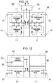
- FIG. 11 is a schematic horizontal sectional view showing a route for introducing and exhausting cooling gas from the power supply device.
- FIG. 12 is a schematic vertical sectional view showing the route for introducing and exhausting cooling gas from the power supply device.
- FIG. 13 is an exploded perspective view showing a secondary battery cell and a separator.
- FIG. 14 is a block diagram showing an example in which the power supply device is mounted in a hybrid car traveling by an engine and a motor.
- FIG. 15 is a block diagram showing an example in which the power supply device is mounted in an electric car traveling only by a motor.
- FIG. 1 to FIG. 9 show power supply device 100 in accordance with a first exemplary embodiment of the present invention.
- Power supply device 100 shown in these drawings shows an example of an on-vehicle power supply device.
- power supply device 100 is mounted mainly in an electric vehicle such as a hybrid car or an electric car, and is used as a power source that supplies power to a travel motor of the vehicle and makes the vehicle travel.
- the power supply device of the present invention can be also used for an electric vehicle other than the hybrid car and electric car, and can be also used for an application requiring a high power, other than the electric vehicle.
- the appearance of power supply device 100 has a substantially box shape extended in one direction.
- power supply device 100 is configured so that the upside and downside of resin-made battery case 20 are covered with metal-made frame 30 .
- Metal frame 30 includes: metal-made lower frame 35 for covering the bottom surface of battery case 20 ; and metal-made upper frame 34 for covering the upper surface of battery case 20 .
- resin-made battery case 20 stores cell assembly 10 inside it.
- Cell assembly 10 is formed of cell stacked bodies 11 produced by stacking secondary battery cells 1 , circuit board 42 , and the like.
- battery case 20 is made of a resin, so that battery case 20 can be molded in various shapes and a waterproof structure can be easily achieved.
- the upper and lower surfaces are covered with metal frame 30 , so that the mechanical strength is secured.
- the heat dissipation is improved by covering the periphery of battery case 20 with metal frame 30 , and the shielding effect by the metal plates can improve the noise immunity of an electronic circuit in the battery case.
- upper frame 34 and lower frame 35 are grasped by upper frame 34 and lower frame 35 . Therefore, upper frame 34 and lower frame 35 are interconnected by tightening screws into fixing pieces 36 disposed on their side surfaces.
- Each of upper frame 34 and lower frame 35 is formed by folding a metal plate. In order to improve the rigidity, a partially folded uneven part or rib may be formed. Examples of this metal plate include a high tensile strength steel having a high rigidity and high thermal conductivity, a general steel, a stainless steel, an aluminum alloy, a magnesium alloy, and a combination of them.
- Lower frame 35 is formed by welding a plurality of metal plates to each other. Lower frame 35 may be formed not only by welding a plurality of metal plates to each other, but also by integrally molding the metal plates by press work.
- Metal frame 30 does not cover the whole periphery of battery case 20 , preferably covers only a necessary part.
- lower frame 35 of metal frame 30 has a bottomed box shape having an open upper surface
- upper frame 34 has a shape allowing a part of the upper surface of battery case 20 to be exposed.
- the side surfaces of battery case 20 may be opened without being covered with metal frame 30 .
- the metal plate is disposed in a part requiring a high strength. While, by omitting the metal plate in a part that does not require a high strength, the surface area requiring the metal plate can be reduced to decrease the weight and cost.
- the exposed region having no metal plate can be thinned by the thickness corresponding to the thickness of the metal plate.
- upper frame 34 is divided into first frame 31 and second frame 32 , and first frame 31 and second frame 32 are disposed separately in spaced relationship with each other.
- exposed region 23 through which a part of battery case 20 is exposed is formed between first frame 31 and second frame 32 .
- the thickness is reduced.
- first frame 31 and second frame 32 are disposed on the portions corresponding to the lower surfaces of seats ST that require a high strength. A part between these portions does not have a metal plate, spaces for disposing necessary members can be secured, and the in-car space can be efficiently used.
- each heat source is transferred more to the metal frame 30 side via battery case 20 than to the inside of battery case 20 .
- the components in battery case 20 can be protected from heat generation.
- the amount of heat generation by the first heat source is different from that by the second heat source—for example, when the amount of heat generation by the first heat source is larger—the following problem is considered:
- First frame 31 and second frame 32 are disposed at the opposite ends in the longitudinal direction of battery case 20 , and exposed region 23 is disposed in the center in the longitudinal direction.
- first heat source and second heat source are disposed in limited-size battery case 20 separately from each other as much as possible, and hence can be effectively and thermally separated from each other.
- Metal frame 30 includes fixing pieces 36 projecting outward, and upper frame 34 and lower frame 35 are fixed to each other by tightening nuts and bolts in screw holes formed in fixing pieces 36 .
- fixing pieces 36 are disposed at four positions of up, down, right, and left in the plan view.
- the screw holes in fixing pieces 36 can be used for fixing power supply device 100 .
- power supply device 100 is screwed to a vehicle using the screw holes.
- battery case 20 is divided into two parts; upper case 21 and lower case 22 .
- battery case 20 is made of a resin, advantageously, even a relatively complicated shape can be easily formed by resin molding.
- a resin is lightweight and inexpensive, and has a high insulation property.
- examples of such a resin material include: polypropylene (PP), polybutylene terephthalate (PBT), polyamide/nylon (PA, trademark), or resins of them; a composite material of glass fiber and glass beads; and a carbon fiber resin.
- a resin-metal composite material integrally molded by grasping a metal mesh and metal plate with a resin may be employed during resin molding.
- An engagement structure is disposed on a joint boundary on which upper case 21 is joined to lower case 22 .
- This structure improves the sealability. Furthermore, by disposing elastic member 24 in the engagement structure, the waterproof property can be further improved.
- packing serving as elastic member 24 is disposed on the joint boundary between upper case 21 and lower case 22 .
- Cell stacked bodies 11 , circuit board 42 , and DC/DC converter 41 are stored in battery case 20 .
- Each cell stacked body 11 is formed by stacking a plurality of secondary battery cells 1 via insulating separators. The opposite end surfaces of each cell stacked body are covered with end plates, and the end plates are fastened to each other via a bond bar.
- Circuit board 42 is mounted on the electronic circuit such as a protection circuit or a control circuit for controlling the charge and discharge of cell stacked bodies 11 .
- DC/DC converter 41 is a member for converting the outputs of cell stacked bodies 11 into a predetermined voltage. For feeding power to electrical components in the vehicle, DC/DC converter 41 converts the outputs of cell stacked bodies 11 into 12 V or 24 V. By building DC/DC converter 41 into battery case 20 in this manner, the conventional arrangement space for DC/DC converter 41 is not required, and hence the whole space is saved.
- DC/DC converter 41 has been conventionally disposed as a separate member.
- a cooling mechanism of cell stacked bodies 11 in battery case 20 can be used also for cooling DC/DC converter 41 , as described below. Therefore, the cooling mechanism for the DC/DC converter, which has been conventionally and separately required, can be omitted. Also at this point, the configuration can be simplified and downsized, and the cost can be reduced.
- DC/DC converter 41 is disposed so as to overlap the region covered with first frame 31 in battery case 20 .
- the shape of first frame 31 , the internal structure of battery case 20 , the size of DC/DC converter 41 , the layout are previously designed so that DC/DC converter 41 is located directly under first frame 31 .
- DC/DC converter 41 is mechanically protected by first frame 31 , and the heat generated by DC/DC converter 41 can be efficiently dissipated out of the power supply device via first frame 31 .
- DC/DC converter 41 is completely stored in the region covered with first frame 31 , but the heat dissipation is improved when the heat source of the DC/DC converter is covered with the first frame. Therefore, it is only required that the first frame and the DC/DC converter are disposed so that they overlap each other in the plan view of the battery case, and the DC/DC converter may partially lie off the first frame.
- Circuit board 42 is disposed in a region covered with second frame 32 .
- the heat generated from a circuit group mounted on circuit board 42 can be dissipated via second frame 32 .
- the shielding effect for the electronic circuit mounted in circuit board 42 is also produced, and the immunity to noise is also improved.
- DC/DC converter 41 is disposed on the first frame 31 side, and circuit board 42 is disposed on the second frame 32 side.
- the present invention is not limited to this configuration.
- the circuit board may be disposed on the first frame side, and the DC/DC converter may be disposed on the second frame side.
- battery case 20 includes a cooling mechanism for dissipating the heat of an internal member.
- the example of FIG. 7 shows an air-cooling type cooling mechanism that takes a cooling gas from the outside, causes the heat exchange in battery case 20 , and exhausts the cooling gas.
- a part of battery case 20 includes intake port 51 for taking a cooling gas into battery case 20 and exhaust port 52 for exhausting the cooling gas after the heat exchange.
- At least one of intake port 51 and exhaust port 52 is disposed in exposed region 23 .
- the surface of battery case 20 can be covered with metal frame 30 , and a region having opening 54 for air-cooling the inside of battery case 20 can be secured. Opening 54 can be projected from the surface of battery case 20 because opening 54 is not covered with the metal frame. As a result, by increasing the opening surface area of opening 54 , the flow rate of the cooling gas can be increased to improve the cooling performance.
- opening 54 is opened in the rear surface of battery case 20 , and is projected upward by height d from the upper surface of battery case 20 .
- Such opening 54 is molded integrally with upper case 21 of battery case 20 . As shown in FIG. 1 and the like, the projection portion is inclined on the upper surface of battery case 20 so as to gradually enlarge toward opening 54 .
- first frame 31 and second frame 32 are disposed along the longitudinal direction of battery case 20 , by disposing an opening for intake or exhaust in the immediate part in the longitudinal direction, a structure where the route of the cooling gas is branched to the first frame 31 side and the second frame 32 side can be employed.
- the cooling gas can be efficiently introduced into or exhausted out of battery case 20 .
- the other of the intake port and exhaust port is formed on a side surface of battery case 20 .
- openings formed in the side surfaces of battery case 20 are set as intake ports 51
- an opening formed in the rear surface of exposed region 23 is set as exhaust port 52 . Therefore, in lower frame 35 , corners corresponding to intake ports 51 are opened.
- gas routes through which cooling gas flows into and goes out of battery case 20 are formed as shown in the schematic horizontal sectional view of FIG. 11 .
- four cell stacked bodies 11 are disposed in battery case 20 at the up, down, right, and left parts in this page. The cooling gas sucked from the up and down parts in right and left side surfaces in FIG.
- the cooling gas is partially used for cooling another member in battery case 20 .
- the cooling gas can be used also for cooling the circuits that are mounted in DC/DC converter 41 as the first heat source and in circuit board 42 as the second heat source.
- intake port 53 for the first heat source is formed in the side surface of battery case 20 and on the disposed side of DC/DC converter 41 .
- Intake port 53 for the first heat source communicates with DC/DC converter 41 , the cooling gas can be taken into battery case 20 through intake port 53 for the first heat source, and DC/DC converter 41 can be cooled by heat exchange.
- the cooling gas after the heat exchange is exhausted out of battery case 20 by blast fans 56 .
- the exhaust route of the cooling gas can be merged with the exhaust route of the cooling gas having cooled cell stacked bodies 11 , as discussed above.
- a partitioning wall is disposed which separates a cooling gas route for cell stacked bodies 11 from a cooling gas route for DC/DC converter 41 .
- a vertically partitioning wall 58 is formed which separates the cooling gas route for cell stacked bodies 11 on the downside in battery case 20 from the cooling gas route for DC/DC converter 41 on the upside in battery case 20 .
- the accidents in which the upside and downside cooling gases before heat exchange mix with each other in battery case 20 can be avoided, and disruption of the balance of the flow rate can be avoided by separating the cooling gas route for cell stacked bodies 11 from that for DC/DC converter 41 .
- the cooling gas that has cooled cell stacked bodies 11 disposed on the downside in battery case 20 is fed upward through the center part in the longitudinal direction of battery case 20 .
- the cooling gas that has cooled DC/DC converter 41 disposed on the upside in battery case 20 is also fed to the center in battery case 20 , joins the cooling gas for cell stacked bodies 11 fed from the downside, and is exhausted together through exhaust port 52 disposed on the rear side of FIG. 12 .
- blast fan 56 for cooling the battery cells can be used also for cooling the heat sources of the circuit or the like, the configuration can be simplified and downsized, and the cost can be reduced.
- a cooling mechanism of DC/DC converter 41 is disposed, but an intake port for cooling the circuit board side is not disposed.
- an intake port or the like for the second heat source may be disposed as a cooling mechanism for cooling the circuit board.
- openings formed in the side surfaces of battery case 20 are set as intake ports 51 , and an opening formed in the rear surface of exposed region 23 is set as exhaust port 52 .
- the present invention is not limited to this configuration.
- openings in the side surfaces of the battery case may be set as exhaust ports, and an opening in the rear surface of the exposed region may be set as an intake port.
- the blast fan is disposed on the intake port side, and forcibly feeds the cooling gas to the components.
- the cooling mechanism may be of the air-cooling type that utilizes not only the air but also a refrigerant gas.
- the means for cooling the power supply device is not limited to an air-cooling type cooling mechanism.
- cooling using a refrigerant may be employed or a cooling mechanism using a Peltier element or the like may be employed.
- Battery case 20 includes one or more recesses 25 in the surface of exposed region 23 . Such recesses 25 can be used for positioning or fixing power supply device 100 .
- Recesses 25 include first recesses 26 disposed on the upper surface side of battery case 20 and second recess 27 disposed on the lower surface side of battery case 20 . In such a configuration where recesses 25 are disposed on the upper and lower surfaces of battery case 20 , the fixing stability and work efficiency can be achieved by positioning battery case 20 from both sides.
- recess 25 for example, second recess 27 —between cell stacked bodies 11 in the longitudinal direction
- a recess can be formed while the arrangement space of cell stacked bodies 11 is secured in battery case 20 .
- power supply device 100 is disposed under seats ST in a cabin of the vehicle. Rails of seats ST are disposed in first recesses 26 in the upper surface.
- first recesses 26 By disposing structurally required first recesses 26 between DC/DC converter 41 and circuit board 42 , DC/DC converter 41 is separated and thermally isolated from circuit board 42 .
- recesses 25 and holding another member in this space a limited space can be efficiently used.
- Cell assembly 10 includes cell stacked bodies 11 and circuit board 42 .
- FIG. 9 shows an exploded perspective view of cell assembly 10 .
- cell assembly 10 includes four cell stacked bodies 11 .
- Two cell stacked bodies 11 are disposed so that their longer surfaces are adjacent to each other, and two sets of them are disposed along the longitudinal direction of battery case 20 .
- the number and layout of the cell stacked bodies are not limited to this example.
- battery case 20 is made of a resin, so that a sealed structure is easily obtained and the dust-proof function and waterproof function can be improved. Furthermore, the insulation property on the bottom surface and side surfaces of the power supply device is improved, so that a structure where the surfaces of secondary battery cells 1 are exposed can be employed. Furthermore, the weight of the power supply device can be reduced.
- Each cell stacked body 11 includes the following components:
- each secondary battery cell 1 The exterior can of each secondary battery cell 1 is exposed. As discussed above, the insulation property is improved by storing cell stacked bodies 11 in resin-made battery case 20 .
- the surface of each secondary battery cell may be coated with an insulating material.
- the surface of the exterior can other than an electrode portion of the secondary battery cell may be covered by thermally fusing a shrinkable tube made of a polyethylene terephthalate (PET) resin or the like.
- PET polyethylene terephthalate
- fastening members 4 are disposed on side surfaces of each cell stacked body 11 having end plates 3 at its opposite ends, are fixed to the pair of end plates 3 , and fasten cell stacked body 11 .
- Each fastening member 4 is formed in a size large enough to cover substantially the whole side surface of cell stacked body 11 .
- Each fastening member 4 includes openings so as to blow the cooling gas to the gap between secondary battery cells 1 .
- Each fastening member may have another shape.
- the fastening member may have a shape in which each of the opposite ends of a metal plate extending in a band shape is folded so as to have a channel-shaped cross section.
- the position at which the fastening member is disposed may be not only on a side surface of cell stacked body 11 but also on the upper surface.
- the structure for fixing the fastening member to an end plate is not limited to screwing.
- a known fixing structure such as a rivet, caulking, welding, or bonding may be appropriately used.
- the exterior can defining the outer shape of each secondary battery cell 1 has a rectangular shape, and its thickness is smaller than its width.
- the exterior can is formed in a bottomed tubular shape whose upside is open, and the opening is blocked by a sealing plate.
- An electrode assembly is stored in the exterior can.
- the sealing plate includes positive and negative electrode terminals, and a gas exhaust valve is disposed between the electrode terminals.
- separator 2 is interposed between opposite main surfaces of adjacent secondary battery cells 1 , and insulates them from each other.
- Separator 2 is formed in a size large enough to cover the whole or the most part of the main surface of secondary battery cell 1 .
- the separator includes, between secondary battery cells 1 , cooling clearances through which a cooling gas is passed.
- Each separator is folded in an uneven shape in the vertical sectional view so as to allow cooling clearances 2 b to be formed between the separator and secondary battery cell 1 .
- cell stacked body 11 is formed by stacking a plurality of secondary battery cells 1 in a state having cooling clearances 2 b .
- the cooling clearances are connected to the cooling mechanism that forcibly feeds the cooling gas such as the air or cold gas and cools secondary battery cells 1 .
- Secondary battery cells 1 are connected to the opposite surfaces of separator 2 in an engagement structure. By using separators 2 connected to secondary battery cells 1 in the engagement structure, adjacent secondary battery cells 1 can be stacked while the positional displacement is inhibited.
- the material of the separators has an insulation property.
- the separators are made of a resin such as plastic, so that the weight and cost can be reduced.
- the separator may be made of a hard member or flexible member.
- a separator having no cooling clearance can be made of a thin flexible material such as a tape-like material.
- the sealability is secured by resin-made battery case 20 , the strength is ensured by partially leaving metal frame 30 , the strength is kept, the waterproof property is achieved, and the weight is reduced.
- the above-mentioned power supply devices can be used as on-vehicle power sources.
- An example of a vehicle equipped with a power supply device includes an electric vehicle such as a hybrid car or plug-in hybrid car that travels by both an engine and a motor, or such as an electric car that travels only by a motor.
- the power supply devices are used as power sources for these vehicles.
- FIG. 14 shows an example in which a power supply device is mounted in a hybrid car that travels by both an engine and a motor.
- Vehicle HV equipped with a power supply device that is shown in this drawing includes: engine 96 and motor 93 for travel that make vehicle HV travel; power supply device 100 for supplying power to motor 93 ; and power generator 94 for charging the battery in power supply device 100 .
- Power supply device 100 is connected to motor 93 and power generator 94 via DC/alternating current (AC) inverter 95 .
- Vehicle HV travels by both of motor 93 and engine 96 while charging and discharging the battery of power supply device 100 .
- Motor 93 is driven when the engine efficiency is low, for example during acceleration or low-speed travel, and makes the vehicle travel.
- Motor 93 receives power from power supply device 100 and is driven.
- Power generator 94 is driven by engine 96 or is driven by regenerative braking when the vehicle is braked, and charges the battery of power supply device 100 .
- FIG. 15 shows an example in which a power supply device is mounted in an electric car traveling only by a motor.
- Vehicle EV equipped with a power supply device that is shown in this drawing includes: motor 93 for travel that makes vehicle EV travel; power supply device 100 for supplying power to motor 93 ; and power generator 94 for charging the battery in power supply device 100 .
- Motor 93 receives power from power supply device 100 and is driven.
- Power generator 94 is driven by energy when regenerative braking is applied to vehicle EV, and charges the battery of power supply device 100 .
- the same names or the same reference marks denote the same members or same-material members, and detailed description is appropriately omitted.
- a plurality of elements may be formed of the same member, and one member may serve as the plurality of elements. Conversely, the function of one member may be shared by the plurality of members.
- a power supply device and a vehicle equipped with the power supply device of the present invention can be suitably used as a power supply device for a plug-in hybrid electric car or hybrid electric car switchable between an electric-vehicle (EV) travel mode and a hybrid-electric-vehicle (HEV) travel mode, or for an electric car.
- the power supply device can be appropriately used for the following applications: a backup power supply device mountable in a rack of a computer sever; a backup power supply device used for wireless base stations of mobile phones; a power source for storage used at home or in a factory; an electric storage device combined with a solar battery, such as a power source for street lights; and a backup power source for traffic lights.
Applications Claiming Priority (3)
| Application Number | Priority Date | Filing Date | Title |
|---|---|---|---|
| JP2015073506 | 2015-03-31 | ||
| JP2015-073506 | 2015-03-31 | ||
| PCT/JP2015/005566 WO2016157263A1 (ja) | 2015-03-31 | 2015-11-06 | 電源装置及びこれを備える車両 |
Publications (2)
| Publication Number | Publication Date |
|---|---|
| US20170365897A1 US20170365897A1 (en) | 2017-12-21 |
| US10879572B2 true US10879572B2 (en) | 2020-12-29 |
Family
ID=57006749
Family Applications (1)
| Application Number | Title | Priority Date | Filing Date |
|---|---|---|---|
| US15/540,376 Active 2036-03-31 US10879572B2 (en) | 2015-03-31 | 2015-11-06 | Power supply device and vehicle provided with same |
Country Status (4)
| Country | Link |
|---|---|
| US (1) | US10879572B2 (ja) |
| JP (1) | JP6400838B2 (ja) |
| CN (1) | CN107210398B (ja) |
| WO (1) | WO2016157263A1 (ja) |
Families Citing this family (10)
| Publication number | Priority date | Publication date | Assignee | Title |
|---|---|---|---|---|
| JP6819491B2 (ja) * | 2017-07-10 | 2021-01-27 | トヨタ自動車株式会社 | 電源装置の製造方法 |
| KR102580847B1 (ko) * | 2018-04-26 | 2023-09-19 | 에스케이온 주식회사 | 배터리 랙 |
| CN109920949B (zh) * | 2019-02-18 | 2021-10-22 | 上海汽车集团股份有限公司 | 轻量化动力电池箱体 |
| KR20210134362A (ko) * | 2019-03-05 | 2021-11-09 | 제네럴 일렉트릭 컴퍼니 | 에너지 저장 시스템의 전력 전자 장치를 냉각하는 시스템 및 방법 |
| KR20210037885A (ko) * | 2019-09-30 | 2021-04-07 | 에스케이이노베이션 주식회사 | 배터리 모듈 |
| CN114365325A (zh) * | 2019-12-06 | 2022-04-15 | 三菱自动车工业株式会社 | 车辆用电池包 |
| DE102019133496B3 (de) * | 2019-12-09 | 2020-12-17 | Dr. Ing. H.C. F. Porsche Aktiengesellschaft | Teilkarosserie für ein wenigstens teilweise elektrisch betriebenes Kraftfahrzeug und Kraftfahrzeug |
| CN111525210B (zh) * | 2020-04-27 | 2021-12-28 | 深圳市元鼎科技有限公司 | 户外电源 |
| JP7443185B2 (ja) * | 2020-07-29 | 2024-03-05 | 本田技研工業株式会社 | 電源装置 |
| CN112510312A (zh) * | 2020-11-09 | 2021-03-16 | 东风汽车集团有限公司 | 一种电动车的动力电池箱 |
Citations (11)
| Publication number | Priority date | Publication date | Assignee | Title |
|---|---|---|---|---|
| JPH05193366A (ja) | 1992-01-22 | 1993-08-03 | Honda Motor Co Ltd | 電気自動車用バッテリの固定構造 |
| US5392873A (en) | 1992-01-22 | 1995-02-28 | Honda Giken Kogyo Kabushiki Kaisha | Structure for securing batteries used in an electric vehicle |
| JP2001167803A (ja) * | 1999-12-09 | 2001-06-22 | Toyota Motor Corp | 電池パック |
| US20100136420A1 (en) * | 2006-09-25 | 2010-06-03 | Lg Chem, Ltd. | Cell-module cartridge and mid-large battery module including the same |
| JP2011049014A (ja) * | 2009-08-26 | 2011-03-10 | Sanyo Electric Co Ltd | 防水構造のバッテリパック |
| JP2011146289A (ja) | 2010-01-15 | 2011-07-28 | Mitsubishi Motors Corp | 車両用バッテリケース |
| US20110222240A1 (en) | 2008-11-17 | 2011-09-15 | Honda Motor Co., Ltd. | Cooling structure for vehicle power source unit |
| US20120164500A1 (en) | 2010-01-15 | 2012-06-28 | Mitsubishi Jidosha Kogyo Kabushiki Kaisha | Automotive battery case |
| US20140124278A1 (en) * | 2012-11-08 | 2014-05-08 | Honda Motor Co., Ltd. | Electrically driven vehicle |
| JP2015008161A (ja) | 2014-09-29 | 2015-01-15 | 三菱自動車工業株式会社 | 電動車のバッテリーパック構造 |
| US20160093932A1 (en) * | 2014-09-30 | 2016-03-31 | Johnson Controls Technology Company | Battery module passive thermal management features and positioning |
Family Cites Families (5)
| Publication number | Priority date | Publication date | Assignee | Title |
|---|---|---|---|---|
| JP4294372B2 (ja) * | 2003-05-21 | 2009-07-08 | 本田技研工業株式会社 | 高圧電装部品の車載構造 |
| JP2011181415A (ja) * | 2010-03-02 | 2011-09-15 | Sanyo Electric Co Ltd | 安定化回路を備えるバッテリパック |
| JP5321554B2 (ja) * | 2010-08-31 | 2013-10-23 | トヨタ自動車株式会社 | 蓄電装置および車両 |
| JP5652377B2 (ja) * | 2011-11-17 | 2015-01-14 | 三菱自動車工業株式会社 | 電動車のバッテリーパック構造 |
| JP5796785B2 (ja) * | 2012-09-28 | 2015-10-21 | 株式会社Gsユアサ | 蓄電装置 |
-
2015
- 2015-11-06 CN CN201580076020.XA patent/CN107210398B/zh active Active
- 2015-11-06 JP JP2017508800A patent/JP6400838B2/ja active Active
- 2015-11-06 WO PCT/JP2015/005566 patent/WO2016157263A1/ja active Application Filing
- 2015-11-06 US US15/540,376 patent/US10879572B2/en active Active
Patent Citations (12)
| Publication number | Priority date | Publication date | Assignee | Title |
|---|---|---|---|---|
| JPH05193366A (ja) | 1992-01-22 | 1993-08-03 | Honda Motor Co Ltd | 電気自動車用バッテリの固定構造 |
| US5392873A (en) | 1992-01-22 | 1995-02-28 | Honda Giken Kogyo Kabushiki Kaisha | Structure for securing batteries used in an electric vehicle |
| JP2001167803A (ja) * | 1999-12-09 | 2001-06-22 | Toyota Motor Corp | 電池パック |
| US20100136420A1 (en) * | 2006-09-25 | 2010-06-03 | Lg Chem, Ltd. | Cell-module cartridge and mid-large battery module including the same |
| US20110222240A1 (en) | 2008-11-17 | 2011-09-15 | Honda Motor Co., Ltd. | Cooling structure for vehicle power source unit |
| CN102216100A (zh) | 2008-11-17 | 2011-10-12 | 本田技研工业株式会社 | 车辆用电源单元的冷却构造 |
| JP2011049014A (ja) * | 2009-08-26 | 2011-03-10 | Sanyo Electric Co Ltd | 防水構造のバッテリパック |
| JP2011146289A (ja) | 2010-01-15 | 2011-07-28 | Mitsubishi Motors Corp | 車両用バッテリケース |
| US20120164500A1 (en) | 2010-01-15 | 2012-06-28 | Mitsubishi Jidosha Kogyo Kabushiki Kaisha | Automotive battery case |
| US20140124278A1 (en) * | 2012-11-08 | 2014-05-08 | Honda Motor Co., Ltd. | Electrically driven vehicle |
| JP2015008161A (ja) | 2014-09-29 | 2015-01-15 | 三菱自動車工業株式会社 | 電動車のバッテリーパック構造 |
| US20160093932A1 (en) * | 2014-09-30 | 2016-03-31 | Johnson Controls Technology Company | Battery module passive thermal management features and positioning |
Non-Patent Citations (4)
| Title |
|---|
| English Translation of Chinese Search Report dated Sep. 30, 2020 for the related Chinese Patent Application No. 201580076020.X. |
| International Search Report of PCT application No. PCT/JP2015/005566 dated Feb. 9, 2016. |
| Machine translation for JP 05-193366 A. (Year: 2019). * |
| Machine translation for JP 2011-049014 A. (Year: 2019). * |
Also Published As
| Publication number | Publication date |
|---|---|
| CN107210398B (zh) | 2021-05-25 |
| JPWO2016157263A1 (ja) | 2017-09-14 |
| CN107210398A (zh) | 2017-09-26 |
| JP6400838B2 (ja) | 2018-10-03 |
| WO2016157263A1 (ja) | 2016-10-06 |
| US20170365897A1 (en) | 2017-12-21 |
Similar Documents
| Publication | Publication Date | Title |
|---|---|---|
| US10879572B2 (en) | Power supply device and vehicle provided with same | |
| JP6878279B2 (ja) | 電源装置及びこれを用いた車両 | |
| US10343548B2 (en) | Onboard battery for vehicle | |
| JP5528772B2 (ja) | 電源装置及びこれを備える車両並びに防水ケース | |
| US7819172B2 (en) | Cooling apparatus for vehicle electrical packaging unit | |
| JP2013171746A (ja) | 電源装置及びこれを備える車両並びに蓄電装置 | |
| JP6189301B2 (ja) | 電源装置及びこれを備える電動車両並びに蓄電装置 | |
| US20120141855A1 (en) | Battery pack for suppressing deviation of central battery cell and vehicle including the same | |
| JP7051862B2 (ja) | バッテリシステム及びこのバッテリシステムを備える車両 | |
| JP2013229182A (ja) | 電源装置、電源装置を備える車両及び蓄電装置 | |
| US10442283B2 (en) | Vehicle body structure | |
| EP3832753A1 (en) | Battery system for vehicle and vehicle equipped with battery system | |
| JP2018060595A (ja) | 電源装置及びこれを備える車両 | |
| US20090273916A1 (en) | Capacitor Apparatus | |
| JP2015133169A (ja) | 電源装置及びこれを備える車両並びに蓄電装置 | |
| US20180190954A1 (en) | Power supply device, and vehicle equipped with same | |
| JP6652030B2 (ja) | 電池装置 | |
| JP6407220B2 (ja) | 電力機器ユニット | |
| WO2021199493A1 (ja) | 電源装置及びこれを備える車両並びに蓄電装置 | |
| US20220247029A1 (en) | Power supply device, electric vehicle using same, and power storage device | |
| WO2014024451A1 (ja) | 電源装置及びこれを備える電動車両並びに蓄電装置 | |
| JP6759007B2 (ja) | 電源装置及びこれを備える車両 | |
| JP2015187912A (ja) | 電源装置の製造方法、電源装置及びこれを備える電動車両並びに蓄電装置 | |
| WO2021010049A1 (ja) | 蓄電装置 | |
| JP2005310461A (ja) | 電池パックの筐体構造 |
Legal Events
| Date | Code | Title | Description |
|---|---|---|---|
| AS | Assignment |
Owner name: SANYO ELECTRIC CO., LTD., JAPAN Free format text: ASSIGNMENT OF ASSIGNORS INTEREST;ASSIGNORS:OKADA, WATARU;UETA, YOSHIAKI;SUGAWARA, SHUICHI;AND OTHERS;SIGNING DATES FROM 20170531 TO 20170615;REEL/FRAME:043349/0435 |
|
| STPP | Information on status: patent application and granting procedure in general |
Free format text: NON FINAL ACTION MAILED |
|
| STPP | Information on status: patent application and granting procedure in general |
Free format text: RESPONSE TO NON-FINAL OFFICE ACTION ENTERED AND FORWARDED TO EXAMINER |
|
| STPP | Information on status: patent application and granting procedure in general |
Free format text: FINAL REJECTION MAILED |
|
| STPP | Information on status: patent application and granting procedure in general |
Free format text: RESPONSE AFTER FINAL ACTION FORWARDED TO EXAMINER |
|
| STPP | Information on status: patent application and granting procedure in general |
Free format text: DOCKETED NEW CASE - READY FOR EXAMINATION |
|
| STPP | Information on status: patent application and granting procedure in general |
Free format text: RESPONSE TO NON-FINAL OFFICE ACTION ENTERED AND FORWARDED TO EXAMINER |
|
| STPP | Information on status: patent application and granting procedure in general |
Free format text: NOTICE OF ALLOWANCE MAILED -- APPLICATION RECEIVED IN OFFICE OF PUBLICATIONS |
|
| STPP | Information on status: patent application and granting procedure in general |
Free format text: PUBLICATIONS -- ISSUE FEE PAYMENT RECEIVED |
|
| STCF | Information on status: patent grant |
Free format text: PATENTED CASE |