US10830485B2 - Air-conditioning diffuser for air distribution - Google Patents
Air-conditioning diffuser for air distribution Download PDFInfo
- Publication number
- US10830485B2 US10830485B2 US15/302,204 US201515302204A US10830485B2 US 10830485 B2 US10830485 B2 US 10830485B2 US 201515302204 A US201515302204 A US 201515302204A US 10830485 B2 US10830485 B2 US 10830485B2
- Authority
- US
- United States
- Prior art keywords
- air
- holes
- conditioning
- outlet wall
- conditioning diffuser
- Prior art date
- Legal status (The legal status is an assumption and is not a legal conclusion. Google has not performed a legal analysis and makes no representation as to the accuracy of the status listed.)
- Active, expires
Links
- 238000004378 air conditioning Methods 0.000 title claims abstract description 57
- 239000011888 foil Substances 0.000 claims abstract description 9
- 239000004745 nonwoven fabric Substances 0.000 claims abstract description 8
- 239000002759 woven fabric Substances 0.000 claims abstract description 8
- 230000001154 acute effect Effects 0.000 claims description 3
- 239000011796 hollow space material Substances 0.000 description 3
- 239000004753 textile Substances 0.000 description 3
- 238000003491 array Methods 0.000 description 2
- 230000002349 favourable effect Effects 0.000 description 1
- 238000004519 manufacturing process Methods 0.000 description 1
- 239000000463 material Substances 0.000 description 1
- 239000007769 metal material Substances 0.000 description 1
- 238000011144 upstream manufacturing Methods 0.000 description 1
Images


Classifications
-
- F—MECHANICAL ENGINEERING; LIGHTING; HEATING; WEAPONS; BLASTING
- F24—HEATING; RANGES; VENTILATING
- F24F—AIR-CONDITIONING; AIR-HUMIDIFICATION; VENTILATION; USE OF AIR CURRENTS FOR SCREENING
- F24F13/00—Details common to, or for air-conditioning, air-humidification, ventilation or use of air currents for screening
- F24F13/02—Ducting arrangements
- F24F13/0218—Flexible soft ducts, e.g. ducts made of permeable textiles
-
- F—MECHANICAL ENGINEERING; LIGHTING; HEATING; WEAPONS; BLASTING
- F24—HEATING; RANGES; VENTILATING
- F24F—AIR-CONDITIONING; AIR-HUMIDIFICATION; VENTILATION; USE OF AIR CURRENTS FOR SCREENING
- F24F13/00—Details common to, or for air-conditioning, air-humidification, ventilation or use of air currents for screening
- F24F13/02—Ducting arrangements
- F24F13/06—Outlets for directing or distributing air into rooms or spaces, e.g. ceiling air diffuser
- F24F13/062—Outlets for directing or distributing air into rooms or spaces, e.g. ceiling air diffuser having one or more bowls or cones diverging in the flow direction
-
- F—MECHANICAL ENGINEERING; LIGHTING; HEATING; WEAPONS; BLASTING
- F24—HEATING; RANGES; VENTILATING
- F24F—AIR-CONDITIONING; AIR-HUMIDIFICATION; VENTILATION; USE OF AIR CURRENTS FOR SCREENING
- F24F13/00—Details common to, or for air-conditioning, air-humidification, ventilation or use of air currents for screening
- F24F13/02—Ducting arrangements
- F24F13/06—Outlets for directing or distributing air into rooms or spaces, e.g. ceiling air diffuser
- F24F13/068—Outlets for directing or distributing air into rooms or spaces, e.g. ceiling air diffuser formed as perforated walls, ceilings or floors
-
- F—MECHANICAL ENGINEERING; LIGHTING; HEATING; WEAPONS; BLASTING
- F24—HEATING; RANGES; VENTILATING
- F24F—AIR-CONDITIONING; AIR-HUMIDIFICATION; VENTILATION; USE OF AIR CURRENTS FOR SCREENING
- F24F13/00—Details common to, or for air-conditioning, air-humidification, ventilation or use of air currents for screening
- F24F13/02—Ducting arrangements
- F24F13/06—Outlets for directing or distributing air into rooms or spaces, e.g. ceiling air diffuser
- F24F2013/0608—Perforated ducts
-
- F—MECHANICAL ENGINEERING; LIGHTING; HEATING; WEAPONS; BLASTING
- F24—HEATING; RANGES; VENTILATING
- F24F—AIR-CONDITIONING; AIR-HUMIDIFICATION; VENTILATION; USE OF AIR CURRENTS FOR SCREENING
- F24F2221/00—Details or features not otherwise provided for
- F24F2221/14—Details or features not otherwise provided for mounted on the ceiling
-
- F—MECHANICAL ENGINEERING; LIGHTING; HEATING; WEAPONS; BLASTING
- F24—HEATING; RANGES; VENTILATING
- F24F—AIR-CONDITIONING; AIR-HUMIDIFICATION; VENTILATION; USE OF AIR CURRENTS FOR SCREENING
- F24F2221/00—Details or features not otherwise provided for
- F24F2221/17—Details or features not otherwise provided for mounted in a wall
Definitions
- the present invention relates to an air-conditioning element for air distribution comprising a chamber provided with an inlet for feeding air and with an outlet wall made of a woven or non-woven fabric or foil, the outlet wall comprising at least one array of through-holes for distributing air into the surrounding environment.
- the known flat air-conditioning diffusers which constitute the prior art concerned and serve for distributing air, are typically made of woven or non-woven fabrics or foils and consist of a framework structure covered with a textile stuffing material (ceiling or wall based diffusers).
- the outlet wall of a diffuser may be perforated or provided with through-holes, the air distribution taking place through such perforation or holes. Distributing air in a proper manner is one of the most important functions of an air conditioning distribution system.
- One of the drawbacks which mainly relate to the known framework structures comprising textile diffusers, consists in that an undesirable draught can develop in the case that the distributed air is flowing in a single direction from such a diffusor.
- FIG. 5 shows a diffuser according to the present invention in a perspective top side view, the diffuser having a downward facing outlet wall
- FIG. 7 shows a particularly preferred embodiment of the diffuser wall
- FIG. 8 shows another preferred embodiment of the air deflecting pocket and the through-hole
- the first exemplary embodiment of the present invention relates to an air-conditioning duct.
- the outlet wall 20 of the air-conditioning duct described herein comprises an array of through-holes 22 for distributing air into the environment surrounding the duct, on the one hand, and an array of auxiliary holes 21 , which are arranged upstream the array of through-holes 22 with respect to the direction of the air flow, on the other hand.
- An air deflector such as an air deflecting pocket 23 , is assigned to each through-hole 22 , said pocket being attached to the outer surface of the corresponding wall of the air-conditioning duct.
- the air deflecting pocket 23 When viewed in a projection which is perpendicular to the outlet wall 20 of the air-conditioning duct, the air deflecting pocket 23 entirely covers the corresponding through-hole 22 from the outside.
- the through-hole 22 leads into a hollow space that is formed between the corresponding air deflecting pocket 23 and the outlet wall 20 of the air-conditioning duct.
- the air deflecting pocket 23 widens towards the array of auxiliary holes 21 and it is also open towards the array of auxiliary holes 21 .
- the air deflecting pocket 23 may assume a shape that is shown in FIGS. 2A and 2B , namely a shape corresponding to a partial lateral area of a cone or truncated cone.
- the through-hole 22 is larger than the auxiliary hole 21 , i.e. the cross-sectional area or the diameter of the through-hole 22 is larger than those of the auxiliary holes 21 .
- the air-conditioning duct works in the following way:
- the inlet 30 of the air-conditioning duct is supplied with air.
- the latter flows through the air-conditioning duct towards the outlet 31 , the direction of such air flow being indicated by means of a wide arrow in FIG. 3 .
- a certain portion of the airflow is exiting the duct via the auxiliary holes 21 .
- the direction of such partial air streams intersects that of the main air flow, which is being fed towards the auxiliary holes 21 inside the air-conditioning duct, at an obtuse angle.
- the air flow, which is exiting via a through-hole 22 is directed by the corresponding air deflecting pocket 23 into a space facing the auxiliary holes 21 on the outer side.
- the direction of the air flow exiting the air deflecting pocket 23 intersects that of the main air flow, which is being fed towards the corresponding auxiliary hole 21 inside the air-conditioning duct, at an acute angle. Consequently, the air flow, which is exiting via the through-hole 22 , will strike the air, which is leaving the auxiliary holes 21 , causing the same to swirl or rectifying the direction of the same towards radial (perpendicular) direction.
- a ceiling or wall based air-conditioning diffuser is concerned herein.
- This diffuser comprises the chamber 10 provided with the inlet 30 for feeding air or for connecting an air supply pipework 6 .
- the chamber 10 is made of a woven or non-woven fabric or foil.
- the chamber 10 further comprises the outlet wall 20 , which is also made of a woven or non-woven fabric or foil, and an array of the through-holes 22 for distributing the air from the chamber 10 into the surrounding environment.
- An air deflecting pocket 23 is assigned to each through-hole 22 , said pocket being attached to the outer surface of the outlet wall 20 of the air-conditioning diffuser.
- the air deflecting pocket 23 entirely covers the corresponding through-hole 22 from the outside when viewed in a projection which is perpendicular to the outlet wall 20 .
- the through-hole 22 leads into an open hollow space that is formed between the corresponding air deflecting pocket 23 and the outlet wall 20 of the air-conditioning diffuser.
- the air deflecting pocket 23 widens towards its outlet orifice 230 .
- the air deflecting pocket 23 may preferably assume a shape that is shown in FIG. 4 or in FIG.
- the lateral sides of the same are attached to the wall of the air-conditioning duct.
- the arrangement of the individual air deflecting pockets 23 enables the respective air streams to be deflected in different directions.
- the air should flow out from the array of the air deflecting pockets 23 in different lateral directions, at least in the area adjoining the corresponding outlet wall 20 .
- the directions of the individual air streams should extend tangentially with respect to a common circle or to a pair or a plurality of concentric circles.
- the direction of the air flow exiting the air deflecting pockets 23 is indicated by means of dashed-line arrows.
- the arrangement of the air deflecting pockets 23 may be adapted to deflect the air streams exiting from the through-holes 22 perpendicularly to the edges of the corresponding outlet wall 20 and/or radially with respect to a circle having its centre in the central area of the outlet wall 20 .
- the air deflecting pockets 23 are generally adapted for diverting the air stream flowing out of the respective through-hole 22 away from the direction, which is perpendicular to the plane of the outlet wall 20 , or for aligning such air stream with the plane of the outlet wall 20 . Again, each individual air deflecting pocket 23 preferably directs the corresponding air stream in a different direction.
- the cross-sectional areas of the through-holes 22 are as large as possible.
- the cross-sectional area of each through-hole may correspond to the area of the perpendicular projection of the hollow space inside the respective air deflecting pocket 23 .
- at least some of the through-holes 22 may have their cross-sectional areas smaller in comparison to the areas of the perpendicular projections of the respective assigned air deflecting pockets 23 .
- the array of the through-holes 22 with the corresponding air deflecting pockets 23 may be supplemented with auxiliary holes 21 , which are not provided with air deflecting pockets 23 assigned to them.
- the auxiliary holes 21 are smaller than the through-holes 22 .
- the auxiliary holes 21 may be formed by providing the outlet wall 20 with a micro-perforated or perforated portion.
- each auxiliary hole 21 has a cross-sectional area ranging between 0.1 and 1 mm 2 , more preferably between 0.15 and 0.3 mm 2 .
- the auxiliary holes 21 are arranged so as to form two arrays, the one array being deployed in a circular plane and the other one being deployed along the circumference of the outlet wall 20 .
- the through-holes 22 are also arranged in two arrays, the one array being deployed inside the circular plane containing the auxiliary holes 21 and the other one being deployed along the circumference of said circular plane.
- the air deflecting pockets 23 which are arranged outside the circular plane containing the auxiliary holes 21 , preferably divert the individual air streams in a substantially tangential direction with respect to a circle that is concentric with the circular plane containing the basic through-holes 22 .
- the air deflecting pockets 23 which are arranged inside said circular plane containing the auxiliary holes 21 , preferably divert the individual air streams in mutually concurrent directions, such concurrent directions being mutually perpendicular ones in the present exemplary embodiment. Nevertheless, said air deflecting pockets may also be seen as diverting the air in directions extending tangentially with respect to a circle that is concentric with the circular plane containing the auxiliary holes 21 .
- the air-conditioning diffuser works in the following way:
- the inlet 30 of the chamber 10 is supplied with the air which subsequently reaches the air-conditioned room via the holes 21 , 22 .
- a certain amount of the air exits via the auxiliary holes 21 , the direction of the corresponding air streams being perpendicular to the outlet wall 20 .
- the air streams, which exit via the through-holes 22 are redirected by the respective air deflecting pockets 23 into a space adjoining the outlet wall 20 , the directions of the individual air streams being different.
- said air streams entrap at least a partial amount of the air flowing out of the auxiliary holes 21 .
- a predominantly swirling or centrifugal direction of the overall air stream flowing out of the air-conditioning diffuser is achieved.
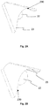
- FIG. 9 shows another exemplary embodiment of the outlet wall 20 of the air-conditioning diffuser according to the present invention.
- the outlet wall 20 comprises an array of through-holes 22 and an array of auxiliary through-holes 21 .
- the outlet wall 20 has a rectangular shape and the through-holes 22 are arranged in two rows, which are parallel to the longer lateral edges of the outlet wall 20 and provided with the air deflecting pockets 23 , the outlet orifices 230 of the air deflecting pockets facing said longer lateral edges of the outlet wall 20 in order to direct the air streams flowing out of the individual through-holes 22 , namely such that the individual air streams conically widen along the plane of the outlet wall 20 .
- the use of the auxiliary through holes 21 is not necessary in any of the above mentioned embodiments, it is considered to be favourable, thus constituting a feature of a preferred embodiment.
- the air deflecting pockets 23 are determinative with respect to the directions of the corresponding air streams.
- the air deflecting pockets 23 are typically not determinative. Nevertheless, they will considerably influence the resulting directions of the corresponding air streams.
- the air-conditioning element including the air deflecting pockets according to the present invention is made of a woven or non-woven fabric or foil.
- it is machine-washable and has a lower weight when compared to an air-conditioning element made of a metallic material.
Applications Claiming Priority (7)
| Application Number | Priority Date | Filing Date | Title |
|---|---|---|---|
| CZ2014-29425U CZ27289U1 (cs) | 2014-04-07 | 2014-04-07 | Vzduchotechnické potrubí |
| CZ2014-29425 | 2014-04-07 | ||
| CZPUV2014-29425 | 2014-04-07 | ||
| CZ2015-30827U CZ28924U1 (cs) | 2015-03-09 | 2015-03-09 | Vzduchotechnická vyústka |
| CZ2015-30827 | 2015-03-09 | ||
| CZPUV2015-30827 | 2015-03-09 | ||
| PCT/CZ2015/000031 WO2015154729A1 (en) | 2014-04-07 | 2015-04-07 | Air-conditioning element for air distribution |
Publications (2)
| Publication Number | Publication Date |
|---|---|
| US20170030608A1 US20170030608A1 (en) | 2017-02-02 |
| US10830485B2 true US10830485B2 (en) | 2020-11-10 |
Family
ID=53188831
Family Applications (1)
| Application Number | Title | Priority Date | Filing Date |
|---|---|---|---|
| US15/302,204 Active 2036-05-07 US10830485B2 (en) | 2014-04-07 | 2015-04-07 | Air-conditioning diffuser for air distribution |
Country Status (10)
| Country | Link |
|---|---|
| US (1) | US10830485B2 (es) |
| EP (1) | EP3129720B1 (es) |
| CN (1) | CN106461261B (es) |
| CA (1) | CA2944364C (es) |
| DK (1) | DK3129720T3 (es) |
| ES (1) | ES2822650T3 (es) |
| LT (1) | LT3129720T (es) |
| MX (1) | MX2016013130A (es) |
| PL (1) | PL3129720T3 (es) |
| WO (1) | WO2015154729A1 (es) |
Families Citing this family (6)
| Publication number | Priority date | Publication date | Assignee | Title |
|---|---|---|---|---|
| WO2015081227A1 (en) * | 2013-11-26 | 2015-06-04 | Dri-Steem Corporation | Steam dispersion system |
| EP3225700A1 (en) | 2016-03-30 | 2017-10-04 | Minkpapir A/S | Drying unit for accommodating a plurality of elongated hollow pelt boards |
| WO2017118721A1 (en) | 2016-01-08 | 2017-07-13 | Minkpapir A/S | Drying unit for accomodating a plurality of elongated hollow pelt boards |
| CZ307411B6 (cs) * | 2017-06-07 | 2018-08-01 | Příhoda S.R.O. | Vzduchotechnická vyústka pro vozidla a vozidlo se vzduchotechnickou vyústkou |
| CZ307470B6 (cs) | 2017-07-18 | 2018-09-26 | Příhoda S.R.O. | Výztužná sestava pro vzduchotechnické potrubí a vzduchotechnické potrubí |
| FR3069622B1 (fr) * | 2017-07-28 | 2019-08-16 | Aero Textile Concept | Diffuseur d'air comprenant un panneau textile |
Citations (52)
| Publication number | Priority date | Publication date | Assignee | Title |
|---|---|---|---|---|
| US2075258A (en) * | 1933-07-01 | 1937-03-30 | American Blower Corp | Gas mixing apparatus |
| US2863606A (en) * | 1955-04-04 | 1958-12-09 | Tatsch Richard | Slip together-snap together convector and conductive conduit means |
| US3733996A (en) * | 1971-01-04 | 1973-05-22 | J Naccarato | Ventilation device |
| US3792595A (en) * | 1972-10-26 | 1974-02-19 | Thermo King Corp | Transportable refrigeration apparatus for preserving perishables |
| US4050365A (en) * | 1976-07-15 | 1977-09-27 | Ever-Wear Products, Inc. | Air distribution assembly |
| US4343506A (en) * | 1980-08-05 | 1982-08-10 | The United States Of America As Represented By The Administrator Of The National Aeronautics And Space Administration | Low-drag ground vehicle particularly suited for use in safely transporting livestock |
| US4354648A (en) * | 1980-02-06 | 1982-10-19 | Gates Learjet Corporation | Airstream modification device for airfoils |
| US5058837A (en) * | 1989-04-07 | 1991-10-22 | Wheeler Gary O | Low drag vortex generators |
| US5598990A (en) * | 1994-12-15 | 1997-02-04 | University Of Kansas Center For Research Inc. | Supersonic vortex generator |
| US5655963A (en) * | 1995-12-04 | 1997-08-12 | Rite-Hite Corporation | Air-releasing endcap for fabric air dispersion system |
| US5807171A (en) * | 1996-06-17 | 1998-09-15 | E.H. Price Limited | Air diffuser apparatus |
| US5833389A (en) * | 1996-12-09 | 1998-11-10 | Orlev Scientific Computing Ltd. | Apparatus for controlling turbulence in boundary layer and other wall-bounded fluid flow fields |
| US6142417A (en) * | 1998-10-26 | 2000-11-07 | Atlantic Research Corporation | Self-deploying air inlet for an air breathing missile |
| US20020056985A1 (en) * | 1998-09-21 | 2002-05-16 | Joseph Szakurski | Truck spray control system |
| US6508076B1 (en) * | 2000-02-03 | 2003-01-21 | Thermo King Corporation | Duct system for temperature-controlled cargo containers |
| US6582011B2 (en) * | 1999-03-09 | 2003-06-24 | Lear Corporation | Vehicle cross car beam |
| US20030190886A1 (en) * | 2002-04-10 | 2003-10-09 | Canon Kabushiki Kaisha | Work working method and apparatus, cassette, and unit for printing apparatus |
| US20040229559A1 (en) | 2003-05-12 | 2004-11-18 | Gebke Kevin J. | Fabric air duct with directional vent |
| WO2006102996A1 (de) | 2005-03-29 | 2006-10-05 | M+W Zander Gebäudetechnik GmbH | Belüftungssystem |
| US20060252365A1 (en) * | 2005-05-04 | 2006-11-09 | Gebke Kevin J | Pliable air duct with pressure responsive discharge outlets |
| US20080203218A1 (en) * | 2007-02-26 | 2008-08-28 | Honeywell International, Inc. | Systems And Methods For Reducing Pressure Loss Of Air Flowing From A First Area To A Second Area |
| US7517279B2 (en) * | 2003-01-27 | 2009-04-14 | Faurecia Innenraum Systeme Gmbh | Vehicle ventilating device |
| US7556223B2 (en) * | 2006-12-04 | 2009-07-07 | The Boeing Company | Vent system for an aerospace vehicle |
| US7625275B1 (en) * | 2006-01-26 | 2009-12-01 | Ford Global Technologies, Llc | Aerodynamic rain-hat for vehicle air intake |
| US20090318072A1 (en) * | 2006-06-07 | 2009-12-24 | Wozair Limited | Blast Protection Damper |
| US7690598B1 (en) * | 2006-09-11 | 2010-04-06 | Plattner Wesley M | Aircraft exhaust vent assembly |
| US20100291852A1 (en) * | 2007-08-06 | 2010-11-18 | Nord-Micro Ag & Co. Ohg | Outflow valve for an aircraft |
| US20100327117A1 (en) * | 2008-02-28 | 2010-12-30 | Alenia Aeronautica S.P.A. | Air intake, in particular for an aircraft chaff dispenser |
| US20110009045A1 (en) * | 2009-07-09 | 2011-01-13 | Beckley Daniel V | Vehicular Interior Assembly |
| EP2357294A2 (de) | 2010-01-29 | 2011-08-17 | H. Lüdi + Co. AG | Mediendecke mit einem flexiblen Zuluftkanal |
| US20110269390A1 (en) * | 2010-05-03 | 2011-11-03 | Cary Pinkalla | Configurable pliable air ducts |
| US20110287708A1 (en) * | 2010-05-20 | 2011-11-24 | Timko Corey V | Food air barrier device |
| US20120006442A1 (en) * | 2010-07-12 | 2012-01-12 | Gebke Kevin J | Configurable pliable air ducts |
| US20120064818A1 (en) * | 2010-08-26 | 2012-03-15 | Kurelowech Richard S | Heat recovery and demand ventilationsystem |
| EP2573479A2 (en) | 2011-08-30 | 2013-03-27 | Prihoda s.r.o. | Duct member for air distribution |
| EP2578957A1 (en) | 2011-10-07 | 2013-04-10 | Prihoda s.r.o. | Duct member comprising a guiding element |
| US8439628B2 (en) * | 2010-01-06 | 2013-05-14 | General Electric Company | Heat transfer enhancement in internal cavities of turbine engine airfoils |
| US20130118493A1 (en) * | 2011-10-25 | 2013-05-16 | Airbus Operations Gmbh | Passenger service module and passenger service system |
| US8544533B2 (en) * | 2005-11-10 | 2013-10-01 | Halla Climate Control Corporation | Vehicular air conditioner having two-layered air flow |
| US20140169825A1 (en) * | 2012-12-13 | 2014-06-19 | Fuji Xerox Co., Ltd. | Blower pipe, blowing device, and image forming apparatus |
| US20140295747A1 (en) * | 2013-04-02 | 2014-10-02 | Airbus Operations Gmbh | Ram air channel assembly and method for operating a ram air channel assembly |
| US8936660B2 (en) * | 2012-06-03 | 2015-01-20 | Jorge Andres CRUZ AGUADO | Ventilation screen |
| US20150072609A1 (en) * | 2012-03-29 | 2015-03-12 | Howorth Air Technology Limited | Clean air apparatus |
| US20150099447A1 (en) * | 2012-10-09 | 2015-04-09 | Matthew Joo How OH | Heat removal apparatus and a method of removing heat |
| US20150110518A1 (en) * | 2013-10-21 | 2015-04-23 | Fuji Xerox Co., Ltd. | Suction pipe, suction device, and image forming apparatus |
| US20160193484A1 (en) * | 2015-01-05 | 2016-07-07 | Airbus Operations Gmbh | Panel for mounting a passenger supply unit and a passenger supply unit |
| US9464532B2 (en) * | 2013-03-05 | 2016-10-11 | Bell Helicopter Textron Inc. | System and method for reducing rotor blade noise |
| US20160377313A1 (en) * | 2015-06-25 | 2016-12-29 | Leiterman And Associates, Inc. | Air duct systems and methods of air flow control |
| US9636967B2 (en) * | 2013-05-13 | 2017-05-02 | Signode Industrial Group Llc | Refrigeration trailer air distribution chute |
| US20180021469A1 (en) * | 2016-07-22 | 2018-01-25 | Lg Electronics Inc. | Ultraviolet sterilization lamp, ultraviolet sterilization module, and air conditioner including ultraviolet sterilization module |
| US10246134B1 (en) * | 2018-05-22 | 2019-04-02 | Nicholas Radyk | Truck mud flap with elbow tubes |
| US10434841B2 (en) * | 2013-01-28 | 2019-10-08 | Thermo King Corporation | System and method of distributing airflow in a transport refrigeration unit |
Family Cites Families (4)
| Publication number | Priority date | Publication date | Assignee | Title |
|---|---|---|---|---|
| DE4417715C1 (de) * | 1994-05-20 | 1995-12-07 | Bree Hartmut | Luftauslaß |
| JP2001219100A (ja) * | 2000-02-09 | 2001-08-14 | Kioritz Corp | 気流案内部材及びその集合体 |
| CN105571095B (zh) * | 2008-12-19 | 2019-03-12 | 凯普股份有限公司 | 空气扩散器和空气循环系统 |
| DE102010044590B4 (de) * | 2010-09-07 | 2022-04-21 | H. Lüdi + Co. Ag | Anordnung zur Belüftung eines Raums, insbesondere eines Laborraums und Verwendung eines Zuluftkanals |
-
2015
- 2015-04-07 DK DK15723115.0T patent/DK3129720T3/da active
- 2015-04-07 US US15/302,204 patent/US10830485B2/en active Active
- 2015-04-07 MX MX2016013130A patent/MX2016013130A/es unknown
- 2015-04-07 CA CA2944364A patent/CA2944364C/en active Active
- 2015-04-07 ES ES15723115T patent/ES2822650T3/es active Active
- 2015-04-07 PL PL15723115T patent/PL3129720T3/pl unknown
- 2015-04-07 CN CN201580018605.6A patent/CN106461261B/zh active Active
- 2015-04-07 WO PCT/CZ2015/000031 patent/WO2015154729A1/en active Application Filing
- 2015-04-07 EP EP15723115.0A patent/EP3129720B1/en active Active
- 2015-04-07 LT LTEP15723115.0T patent/LT3129720T/lt unknown
Patent Citations (53)
| Publication number | Priority date | Publication date | Assignee | Title |
|---|---|---|---|---|
| US2075258A (en) * | 1933-07-01 | 1937-03-30 | American Blower Corp | Gas mixing apparatus |
| US2863606A (en) * | 1955-04-04 | 1958-12-09 | Tatsch Richard | Slip together-snap together convector and conductive conduit means |
| US3733996A (en) * | 1971-01-04 | 1973-05-22 | J Naccarato | Ventilation device |
| US3792595A (en) * | 1972-10-26 | 1974-02-19 | Thermo King Corp | Transportable refrigeration apparatus for preserving perishables |
| US4050365A (en) * | 1976-07-15 | 1977-09-27 | Ever-Wear Products, Inc. | Air distribution assembly |
| US4354648A (en) * | 1980-02-06 | 1982-10-19 | Gates Learjet Corporation | Airstream modification device for airfoils |
| US4343506A (en) * | 1980-08-05 | 1982-08-10 | The United States Of America As Represented By The Administrator Of The National Aeronautics And Space Administration | Low-drag ground vehicle particularly suited for use in safely transporting livestock |
| US5058837A (en) * | 1989-04-07 | 1991-10-22 | Wheeler Gary O | Low drag vortex generators |
| US5598990A (en) * | 1994-12-15 | 1997-02-04 | University Of Kansas Center For Research Inc. | Supersonic vortex generator |
| US5655963A (en) * | 1995-12-04 | 1997-08-12 | Rite-Hite Corporation | Air-releasing endcap for fabric air dispersion system |
| US5807171A (en) * | 1996-06-17 | 1998-09-15 | E.H. Price Limited | Air diffuser apparatus |
| US5833389A (en) * | 1996-12-09 | 1998-11-10 | Orlev Scientific Computing Ltd. | Apparatus for controlling turbulence in boundary layer and other wall-bounded fluid flow fields |
| US20020056985A1 (en) * | 1998-09-21 | 2002-05-16 | Joseph Szakurski | Truck spray control system |
| US6142417A (en) * | 1998-10-26 | 2000-11-07 | Atlantic Research Corporation | Self-deploying air inlet for an air breathing missile |
| US6582011B2 (en) * | 1999-03-09 | 2003-06-24 | Lear Corporation | Vehicle cross car beam |
| US6508076B1 (en) * | 2000-02-03 | 2003-01-21 | Thermo King Corporation | Duct system for temperature-controlled cargo containers |
| US20030190886A1 (en) * | 2002-04-10 | 2003-10-09 | Canon Kabushiki Kaisha | Work working method and apparatus, cassette, and unit for printing apparatus |
| US7517279B2 (en) * | 2003-01-27 | 2009-04-14 | Faurecia Innenraum Systeme Gmbh | Vehicle ventilating device |
| US20040229559A1 (en) | 2003-05-12 | 2004-11-18 | Gebke Kevin J. | Fabric air duct with directional vent |
| WO2006102996A1 (de) | 2005-03-29 | 2006-10-05 | M+W Zander Gebäudetechnik GmbH | Belüftungssystem |
| US20060252365A1 (en) * | 2005-05-04 | 2006-11-09 | Gebke Kevin J | Pliable air duct with pressure responsive discharge outlets |
| US8544533B2 (en) * | 2005-11-10 | 2013-10-01 | Halla Climate Control Corporation | Vehicular air conditioner having two-layered air flow |
| US7625275B1 (en) * | 2006-01-26 | 2009-12-01 | Ford Global Technologies, Llc | Aerodynamic rain-hat for vehicle air intake |
| US20090318072A1 (en) * | 2006-06-07 | 2009-12-24 | Wozair Limited | Blast Protection Damper |
| US7690598B1 (en) * | 2006-09-11 | 2010-04-06 | Plattner Wesley M | Aircraft exhaust vent assembly |
| US7556223B2 (en) * | 2006-12-04 | 2009-07-07 | The Boeing Company | Vent system for an aerospace vehicle |
| US20080203218A1 (en) * | 2007-02-26 | 2008-08-28 | Honeywell International, Inc. | Systems And Methods For Reducing Pressure Loss Of Air Flowing From A First Area To A Second Area |
| US20100291852A1 (en) * | 2007-08-06 | 2010-11-18 | Nord-Micro Ag & Co. Ohg | Outflow valve for an aircraft |
| US20100327117A1 (en) * | 2008-02-28 | 2010-12-30 | Alenia Aeronautica S.P.A. | Air intake, in particular for an aircraft chaff dispenser |
| US20110009045A1 (en) * | 2009-07-09 | 2011-01-13 | Beckley Daniel V | Vehicular Interior Assembly |
| US8439628B2 (en) * | 2010-01-06 | 2013-05-14 | General Electric Company | Heat transfer enhancement in internal cavities of turbine engine airfoils |
| EP2357294A2 (de) | 2010-01-29 | 2011-08-17 | H. Lüdi + Co. AG | Mediendecke mit einem flexiblen Zuluftkanal |
| US20110269390A1 (en) * | 2010-05-03 | 2011-11-03 | Cary Pinkalla | Configurable pliable air ducts |
| US20110287708A1 (en) * | 2010-05-20 | 2011-11-24 | Timko Corey V | Food air barrier device |
| US20120006442A1 (en) * | 2010-07-12 | 2012-01-12 | Gebke Kevin J | Configurable pliable air ducts |
| US8808075B2 (en) * | 2010-07-12 | 2014-08-19 | Rite-Hite Holding Corporation | Configurable pliable air ducts |
| US20120064818A1 (en) * | 2010-08-26 | 2012-03-15 | Kurelowech Richard S | Heat recovery and demand ventilationsystem |
| EP2573479A2 (en) | 2011-08-30 | 2013-03-27 | Prihoda s.r.o. | Duct member for air distribution |
| EP2578957A1 (en) | 2011-10-07 | 2013-04-10 | Prihoda s.r.o. | Duct member comprising a guiding element |
| US20130118493A1 (en) * | 2011-10-25 | 2013-05-16 | Airbus Operations Gmbh | Passenger service module and passenger service system |
| US20150072609A1 (en) * | 2012-03-29 | 2015-03-12 | Howorth Air Technology Limited | Clean air apparatus |
| US8936660B2 (en) * | 2012-06-03 | 2015-01-20 | Jorge Andres CRUZ AGUADO | Ventilation screen |
| US20150099447A1 (en) * | 2012-10-09 | 2015-04-09 | Matthew Joo How OH | Heat removal apparatus and a method of removing heat |
| US20140169825A1 (en) * | 2012-12-13 | 2014-06-19 | Fuji Xerox Co., Ltd. | Blower pipe, blowing device, and image forming apparatus |
| US10434841B2 (en) * | 2013-01-28 | 2019-10-08 | Thermo King Corporation | System and method of distributing airflow in a transport refrigeration unit |
| US9464532B2 (en) * | 2013-03-05 | 2016-10-11 | Bell Helicopter Textron Inc. | System and method for reducing rotor blade noise |
| US20140295747A1 (en) * | 2013-04-02 | 2014-10-02 | Airbus Operations Gmbh | Ram air channel assembly and method for operating a ram air channel assembly |
| US9636967B2 (en) * | 2013-05-13 | 2017-05-02 | Signode Industrial Group Llc | Refrigeration trailer air distribution chute |
| US20150110518A1 (en) * | 2013-10-21 | 2015-04-23 | Fuji Xerox Co., Ltd. | Suction pipe, suction device, and image forming apparatus |
| US20160193484A1 (en) * | 2015-01-05 | 2016-07-07 | Airbus Operations Gmbh | Panel for mounting a passenger supply unit and a passenger supply unit |
| US20160377313A1 (en) * | 2015-06-25 | 2016-12-29 | Leiterman And Associates, Inc. | Air duct systems and methods of air flow control |
| US20180021469A1 (en) * | 2016-07-22 | 2018-01-25 | Lg Electronics Inc. | Ultraviolet sterilization lamp, ultraviolet sterilization module, and air conditioner including ultraviolet sterilization module |
| US10246134B1 (en) * | 2018-05-22 | 2019-04-02 | Nicholas Radyk | Truck mud flap with elbow tubes |
Non-Patent Citations (1)
| Title |
|---|
| International Searching Authority, International Search Report and Written Opinion issued in International Application No. PCT/CZ2015/000031, dated Jul. 7, 2015, 9 pages. |
Also Published As
| Publication number | Publication date |
|---|---|
| EP3129720A1 (en) | 2017-02-15 |
| CA2944364A1 (en) | 2015-10-15 |
| WO2015154729A1 (en) | 2015-10-15 |
| PL3129720T3 (pl) | 2021-01-11 |
| CA2944364C (en) | 2021-12-07 |
| CN106461261B (zh) | 2020-04-03 |
| CN106461261A (zh) | 2017-02-22 |
| LT3129720T (lt) | 2020-11-10 |
| ES2822650T3 (es) | 2021-05-04 |
| MX2016013130A (es) | 2017-02-14 |
| US20170030608A1 (en) | 2017-02-02 |
| DK3129720T3 (da) | 2020-10-19 |
| EP3129720B1 (en) | 2020-07-22 |
Similar Documents
| Publication | Publication Date | Title |
|---|---|---|
| US10830485B2 (en) | Air-conditioning diffuser for air distribution | |
| US20160242325A1 (en) | Directional grate access floor panel | |
| EP3722126B1 (en) | Air vent | |
| US20060211365A1 (en) | Induction diffuser | |
| US20110294409A1 (en) | Side Feeder Air Guiding Element For An Aircraft Air-Conditioning System | |
| US20080209870A1 (en) | Gas diffusion device | |
| CA2926565C (en) | Fabric air outlet device | |
| CN107763828A (zh) | 防啸叫噪音网罩、具有该网罩的出风口结构及空调器 | |
| WO2018224061A1 (en) | Air conditioning diffuser | |
| CZ27289U1 (cs) | Vzduchotechnické potrubí | |
| US3232206A (en) | Face plate for an air distribution outlet | |
| CN214841572U (zh) | 散风组件、空调室内机及空调器 | |
| KR100214754B1 (ko) | 송풍장치 | |
| CZ28924U1 (cs) | Vzduchotechnická vyústka | |
| CN108431508B (zh) | 供气装置 | |
| JP2022029351A (ja) | 空調用吹出口ユニット | |
| JP6600030B2 (ja) | 空気式放射ユニット | |
| ES2464997T3 (es) | Salida, especialmente salida vorticial, para la ventilación de habitaciones | |
| WO2018021968A1 (en) | Outlet vent panel | |
| JP6813973B2 (ja) | 空調用チャンバダクト | |
| JP7232462B2 (ja) | 吹出口装置 | |
| KR20160108513A (ko) | 증가된 공기 유도율을 가지는 유도급기 단말유니트 및 증가된 공기 유도율을 제공하는 방법 | |
| JP5502665B2 (ja) | 吹出口装置 | |
| AU2002313921B2 (en) | Induction Diffuser | |
| CN114719336A (zh) | 散风组件、空调室内机及空调器 |
Legal Events
| Date | Code | Title | Description |
|---|---|---|---|
| AS | Assignment |
Owner name: PRIHODA S.R.O., CZECH REPUBLIC Free format text: ASSIGNMENT OF ASSIGNORS INTEREST;ASSIGNORS:PRIHODA, ZDENEK;BURES, MICHAL;REEL/FRAME:041477/0074 Effective date: 20161006 |
|
| STPP | Information on status: patent application and granting procedure in general |
Free format text: RESPONSE TO NON-FINAL OFFICE ACTION ENTERED AND FORWARDED TO EXAMINER |
|
| STPP | Information on status: patent application and granting procedure in general |
Free format text: FINAL REJECTION MAILED |
|
| STPP | Information on status: patent application and granting procedure in general |
Free format text: DOCKETED NEW CASE - READY FOR EXAMINATION |
|
| STPP | Information on status: patent application and granting procedure in general |
Free format text: PUBLICATIONS -- ISSUE FEE PAYMENT RECEIVED |
|
| STCF | Information on status: patent grant |
Free format text: PATENTED CASE |
|
| MAFP | Maintenance fee payment |
Free format text: PAYMENT OF MAINTENANCE FEE, 4TH YR, SMALL ENTITY (ORIGINAL EVENT CODE: M2551); ENTITY STATUS OF PATENT OWNER: SMALL ENTITY Year of fee payment: 4 |