US10828845B2 - Wire material for elastic member and elastic member - Google Patents
Wire material for elastic member and elastic member Download PDFInfo
- Publication number
- US10828845B2 US10828845B2 US15/768,212 US201615768212A US10828845B2 US 10828845 B2 US10828845 B2 US 10828845B2 US 201615768212 A US201615768212 A US 201615768212A US 10828845 B2 US10828845 B2 US 10828845B2
- Authority
- US
- United States
- Prior art keywords
- side reinforced
- elastic member
- wire material
- reinforced fibers
- inner circumferential
- Prior art date
- Legal status (The legal status is an assumption and is not a legal conclusion. Google has not performed a legal analysis and makes no representation as to the accuracy of the status listed.)
- Active, expires
Links
- 239000000463 material Substances 0.000 title claims abstract description 117
- 239000000835 fiber Substances 0.000 claims abstract description 186
- 238000004804 winding Methods 0.000 claims abstract description 59
- 229920005989 resin Polymers 0.000 claims abstract description 22
- 239000011347 resin Substances 0.000 claims abstract description 22
- 229920001187 thermosetting polymer Polymers 0.000 claims abstract description 15
- 239000000725 suspension Substances 0.000 claims description 12
- 230000003068 static effect Effects 0.000 claims description 7
- 229920002430 Fibre-reinforced plastic Polymers 0.000 description 16
- 239000011151 fibre-reinforced plastic Substances 0.000 description 16
- 230000000052 comparative effect Effects 0.000 description 9
- 229920000049 Carbon (fiber) Polymers 0.000 description 6
- 239000004917 carbon fiber Substances 0.000 description 6
- 238000000034 method Methods 0.000 description 6
- 238000004519 manufacturing process Methods 0.000 description 5
- 239000004743 Polypropylene Substances 0.000 description 4
- 230000008602 contraction Effects 0.000 description 4
- 239000003822 epoxy resin Substances 0.000 description 4
- 229920000647 polyepoxide Polymers 0.000 description 4
- 229920001155 polypropylene Polymers 0.000 description 4
- 230000006835 compression Effects 0.000 description 3
- 238000007906 compression Methods 0.000 description 3
- 230000000694 effects Effects 0.000 description 3
- VNWKTOKETHGBQD-UHFFFAOYSA-N methane Chemical compound C VNWKTOKETHGBQD-UHFFFAOYSA-N 0.000 description 3
- 238000010008 shearing Methods 0.000 description 3
- 229910001018 Cast iron Inorganic materials 0.000 description 2
- XEEYBQQBJWHFJM-UHFFFAOYSA-N Iron Chemical compound [Fe] XEEYBQQBJWHFJM-UHFFFAOYSA-N 0.000 description 2
- XAGFODPZIPBFFR-UHFFFAOYSA-N aluminium Chemical compound [Al] XAGFODPZIPBFFR-UHFFFAOYSA-N 0.000 description 2
- 229910052782 aluminium Inorganic materials 0.000 description 2
- 239000004760 aramid Substances 0.000 description 2
- 238000010438 heat treatment Methods 0.000 description 2
- -1 polypropylene Polymers 0.000 description 2
- 229910000838 Al alloy Inorganic materials 0.000 description 1
- 229920002748 Basalt fiber Polymers 0.000 description 1
- 229910000861 Mg alloy Inorganic materials 0.000 description 1
- 229910000831 Steel Inorganic materials 0.000 description 1
- 229910045601 alloy Inorganic materials 0.000 description 1
- 239000000956 alloy Substances 0.000 description 1
- AZDRQVAHHNSJOQ-UHFFFAOYSA-N alumane Chemical group [AlH3] AZDRQVAHHNSJOQ-UHFFFAOYSA-N 0.000 description 1
- 229920006231 aramid fiber Polymers 0.000 description 1
- 229920003235 aromatic polyamide Polymers 0.000 description 1
- 238000005452 bending Methods 0.000 description 1
- 230000015572 biosynthetic process Effects 0.000 description 1
- 239000012141 concentrate Substances 0.000 description 1
- 238000002474 experimental method Methods 0.000 description 1
- 238000009730 filament winding Methods 0.000 description 1
- 239000000446 fuel Substances 0.000 description 1
- 239000003365 glass fiber Substances 0.000 description 1
- 229910052742 iron Inorganic materials 0.000 description 1
- 239000003381 stabilizer Substances 0.000 description 1
- 239000010959 steel Substances 0.000 description 1
- 239000013585 weight reducing agent Substances 0.000 description 1
Images


Classifications
-
- B—PERFORMING OPERATIONS; TRANSPORTING
- B29—WORKING OF PLASTICS; WORKING OF SUBSTANCES IN A PLASTIC STATE IN GENERAL
- B29C—SHAPING OR JOINING OF PLASTICS; SHAPING OF MATERIAL IN A PLASTIC STATE, NOT OTHERWISE PROVIDED FOR; AFTER-TREATMENT OF THE SHAPED PRODUCTS, e.g. REPAIRING
- B29C70/00—Shaping composites, i.e. plastics material comprising reinforcements, fillers or preformed parts, e.g. inserts
- B29C70/04—Shaping composites, i.e. plastics material comprising reinforcements, fillers or preformed parts, e.g. inserts comprising reinforcements only, e.g. self-reinforcing plastics
- B29C70/06—Fibrous reinforcements only
- B29C70/10—Fibrous reinforcements only characterised by the structure of fibrous reinforcements, e.g. hollow fibres
- B29C70/16—Fibrous reinforcements only characterised by the structure of fibrous reinforcements, e.g. hollow fibres using fibres of substantial or continuous length
-
- B—PERFORMING OPERATIONS; TRANSPORTING
- B29—WORKING OF PLASTICS; WORKING OF SUBSTANCES IN A PLASTIC STATE IN GENERAL
- B29C—SHAPING OR JOINING OF PLASTICS; SHAPING OF MATERIAL IN A PLASTIC STATE, NOT OTHERWISE PROVIDED FOR; AFTER-TREATMENT OF THE SHAPED PRODUCTS, e.g. REPAIRING
- B29C70/00—Shaping composites, i.e. plastics material comprising reinforcements, fillers or preformed parts, e.g. inserts
- B29C70/04—Shaping composites, i.e. plastics material comprising reinforcements, fillers or preformed parts, e.g. inserts comprising reinforcements only, e.g. self-reinforcing plastics
- B29C70/28—Shaping operations therefor
- B29C70/30—Shaping by lay-up, i.e. applying fibres, tape or broadsheet on a mould, former or core; Shaping by spray-up, i.e. spraying of fibres on a mould, former or core
- B29C70/32—Shaping by lay-up, i.e. applying fibres, tape or broadsheet on a mould, former or core; Shaping by spray-up, i.e. spraying of fibres on a mould, former or core on a rotating mould, former or core
-
- B—PERFORMING OPERATIONS; TRANSPORTING
- B29—WORKING OF PLASTICS; WORKING OF SUBSTANCES IN A PLASTIC STATE IN GENERAL
- B29C—SHAPING OR JOINING OF PLASTICS; SHAPING OF MATERIAL IN A PLASTIC STATE, NOT OTHERWISE PROVIDED FOR; AFTER-TREATMENT OF THE SHAPED PRODUCTS, e.g. REPAIRING
- B29C53/00—Shaping by bending, folding, twisting, straightening or flattening; Apparatus therefor
- B29C53/02—Bending or folding
- B29C53/08—Bending or folding of tubes or other profiled members
-
- B—PERFORMING OPERATIONS; TRANSPORTING
- B29—WORKING OF PLASTICS; WORKING OF SUBSTANCES IN A PLASTIC STATE IN GENERAL
- B29C—SHAPING OR JOINING OF PLASTICS; SHAPING OF MATERIAL IN A PLASTIC STATE, NOT OTHERWISE PROVIDED FOR; AFTER-TREATMENT OF THE SHAPED PRODUCTS, e.g. REPAIRING
- B29C53/00—Shaping by bending, folding, twisting, straightening or flattening; Apparatus therefor
- B29C53/02—Bending or folding
- B29C53/12—Bending or folding helically, e.g. for making springs
-
- B—PERFORMING OPERATIONS; TRANSPORTING
- B29—WORKING OF PLASTICS; WORKING OF SUBSTANCES IN A PLASTIC STATE IN GENERAL
- B29C—SHAPING OR JOINING OF PLASTICS; SHAPING OF MATERIAL IN A PLASTIC STATE, NOT OTHERWISE PROVIDED FOR; AFTER-TREATMENT OF THE SHAPED PRODUCTS, e.g. REPAIRING
- B29C70/00—Shaping composites, i.e. plastics material comprising reinforcements, fillers or preformed parts, e.g. inserts
- B29C70/04—Shaping composites, i.e. plastics material comprising reinforcements, fillers or preformed parts, e.g. inserts comprising reinforcements only, e.g. self-reinforcing plastics
- B29C70/06—Fibrous reinforcements only
-
- F—MECHANICAL ENGINEERING; LIGHTING; HEATING; WEAPONS; BLASTING
- F16—ENGINEERING ELEMENTS AND UNITS; GENERAL MEASURES FOR PRODUCING AND MAINTAINING EFFECTIVE FUNCTIONING OF MACHINES OR INSTALLATIONS; THERMAL INSULATION IN GENERAL
- F16F—SPRINGS; SHOCK-ABSORBERS; MEANS FOR DAMPING VIBRATION
- F16F1/00—Springs
- F16F1/02—Springs made of steel or other material having low internal friction; Wound, torsion, leaf, cup, ring or the like springs, the material of the spring not being relevant
- F16F1/021—Springs made of steel or other material having low internal friction; Wound, torsion, leaf, cup, ring or the like springs, the material of the spring not being relevant characterised by their composition, e.g. comprising materials providing for particular spring properties
-
- F—MECHANICAL ENGINEERING; LIGHTING; HEATING; WEAPONS; BLASTING
- F16—ENGINEERING ELEMENTS AND UNITS; GENERAL MEASURES FOR PRODUCING AND MAINTAINING EFFECTIVE FUNCTIONING OF MACHINES OR INSTALLATIONS; THERMAL INSULATION IN GENERAL
- F16F—SPRINGS; SHOCK-ABSORBERS; MEANS FOR DAMPING VIBRATION
- F16F1/00—Springs
- F16F1/02—Springs made of steel or other material having low internal friction; Wound, torsion, leaf, cup, ring or the like springs, the material of the spring not being relevant
- F16F1/04—Wound springs
- F16F1/06—Wound springs with turns lying in cylindrical surfaces
-
- F—MECHANICAL ENGINEERING; LIGHTING; HEATING; WEAPONS; BLASTING
- F16—ENGINEERING ELEMENTS AND UNITS; GENERAL MEASURES FOR PRODUCING AND MAINTAINING EFFECTIVE FUNCTIONING OF MACHINES OR INSTALLATIONS; THERMAL INSULATION IN GENERAL
- F16F—SPRINGS; SHOCK-ABSORBERS; MEANS FOR DAMPING VIBRATION
- F16F1/00—Springs
- F16F1/36—Springs made of rubber or other material having high internal friction, e.g. thermoplastic elastomers
- F16F1/366—Springs made of rubber or other material having high internal friction, e.g. thermoplastic elastomers made of fibre-reinforced plastics, i.e. characterised by their special construction from such materials
- F16F1/3665—Wound springs
-
- B—PERFORMING OPERATIONS; TRANSPORTING
- B29—WORKING OF PLASTICS; WORKING OF SUBSTANCES IN A PLASTIC STATE IN GENERAL
- B29L—INDEXING SCHEME ASSOCIATED WITH SUBCLASS B29C, RELATING TO PARTICULAR ARTICLES
- B29L2031/00—Other particular articles
- B29L2031/772—Articles characterised by their shape and not otherwise provided for
- B29L2031/7732—Helical
-
- B—PERFORMING OPERATIONS; TRANSPORTING
- B29—WORKING OF PLASTICS; WORKING OF SUBSTANCES IN A PLASTIC STATE IN GENERAL
- B29L—INDEXING SCHEME ASSOCIATED WITH SUBCLASS B29C, RELATING TO PARTICULAR ARTICLES
- B29L2031/00—Other particular articles
- B29L2031/774—Springs
- B29L2031/7742—Springs helical springs
-
- F—MECHANICAL ENGINEERING; LIGHTING; HEATING; WEAPONS; BLASTING
- F16—ENGINEERING ELEMENTS AND UNITS; GENERAL MEASURES FOR PRODUCING AND MAINTAINING EFFECTIVE FUNCTIONING OF MACHINES OR INSTALLATIONS; THERMAL INSULATION IN GENERAL
- F16F—SPRINGS; SHOCK-ABSORBERS; MEANS FOR DAMPING VIBRATION
- F16F2228/00—Functional characteristics, e.g. variability, frequency-dependence
- F16F2228/001—Specific functional characteristics in numerical form or in the form of equations
- F16F2228/005—Material properties, e.g. moduli
- F16F2228/007—Material properties, e.g. moduli of solids, e.g. hardness
Definitions
- the present invention relates to a wire material for an elastic member, and an elastic member.
- elastic members such as coil springs as suspension springs for suspension are considered for reduction in weight.
- wire materials for elastic members that can reduce the elastic members in weight include wire materials for elastic members that have fibers such as carbon fibers wound around a core member and a fiber reinforced resin layer made of resin (for example, see Patent Documents 1 to 3).
- Patent Document 1 discloses a wire material for an elastic member that uses aluminum as a core member and has a carbon fiber reinforced resin layer formed by winding fibers around the outer circumference of the aluminum core member in a mesh manner.
- the winding of the fibers around the core member in the mesh manner as disclosed in Patent Document 1 is however easy to cause buckling breakage of the fibers when torsional stress is applied thereto and the diameter of the wire material is therefore required to be increased in order to ensure strength. Due to the increase in the diameter of the wire material, a sufficient weight reduction effect and a necessary deflection amount cannot be provided and there is the risk that the coil spring does not exert its function.
- Patent Document 2 discloses a wire material for an elastic member that is formed by winding fibers around a core member with a predetermined angle with respect to the axial direction of the core member, as a technique of improving strength against torsional stress.
- Patent Document 3 discloses that when a wire material for an elastic member is wound to form a coil spring, the orientation direction of fibers with respect to the axial direction of a core member is the direction with which shearing acting on the coil spring in a usage state applies tension force to the fibers.
- Patent Literature 1 Japanese Utility Model Application Publication No. S55-45076
- Patent Literature 2 Japanese Patent Application Laid-open No. 2006-226327
- Patent Literature 3 Japanese Utility Model Application Publication No. H3-19140
- the present invention has been made in view of the above-described circumstances and an object thereof is to provide a wire material for an elastic member and the elastic member that can achieve reduction in weight and improvement in strength.
- a wire material for an elastic member for producing an elastic member includes: inner circumferential-side reinforced fibers that are wound in a spiral form; outer circumferential-side reinforced fibers that are provided on an outer circumference of the inner circumferential-side reinforced fibers; and thermosetting resin that is provided in at least a part of the inner circumferential-side reinforced fibers and the outer circumferential-side reinforced fibers and firmly fixes the reinforced fibers with each other, wherein an angle formed by a winding direction of the inner circumferential-side reinforced fibers and a center axis of the winding is 70° to 110°, and a winding direction of the outer circumferential-side reinforced fibers with respect to a center axis of the winding is along a direction of a tensile load that is applied to the wire material for the elastic member in accordance with a load applying torsional stress to the wire material for the elastic member as an externally applied load.
- an angle formed by the center axis of the winding of the outer circumferential-side reinforced fibers and the winding direction of the outer circumferential-side reinforced fibers is 40° to 50°.
- rigidity of the wire material for the elastic member is equal to or higher than 9 GPa.
- a ratio of a thickness of an outer circumferential-side reinforced fiber layer containing the outer circumferential-side reinforced fibers relative to a thickness of an inner circumferential-side reinforced fiber layer containing the inner circumferential-side reinforced fibers is equal to or higher than 0.5.
- a static torsional strength of the wire material for the elastic member is equal to or higher than 540 MPa.
- the wire material for an elastic member according to the present invention further includes a core member that is provided at an inner circumferential side of a tubular inner circumferential-side reinforced fiber layer formed by the inner circumferential-side reinforced fibers and is formed using an elastically deformable material.
- the core member and the wire material for the elastic member have circular cross sections and a plane orthogonal to a lengthwise axis is a cutting surface, and the angle formed by the winding direction of the inner circumferential-side reinforced fibers and the center axis of the winding is 80° to 100°.
- an elastic member according to the present invention is formed by using the wire material for an elastic member according to the above-described invention.
- the elastic member is formed by winding the wire material for an elastic member in a spiral manner.
- the elastic member is a suspension spring for an automobile.
- the present invention provides effects of achieving reduction in weight and improvement in strength.
- FIG. 1 is a schematic plan view illustrating the configuration of a coil spring according to an embodiment of the present invention.
- FIG. 2 is a schematic plan view illustrating the configuration of a main part of the coil spring in the embodiment of the present invention.
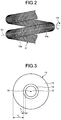
- FIG. 3 is a schematic plan view illustrating the configuration of the main part of the coil spring in the embodiment of the present invention.
- FIG. 4A is a schematic plan view illustrating the configuration of the main part of the coil spring in the embodiment of the present invention.
- FIG. 4B is a schematic plan view illustrating the configuration of the main part of the coil spring in the embodiment of the present invention.
- FIG. 5 is a schematic plan view illustrating the configuration of a wire material for an elastic member for producing the coil spring in the embodiment of the present invention.
- FIG. 6 is a view for explaining a method for producing the wire material of the elastic member in the embodiment of the present invention.
- FIG. 7 is a view for explaining the method for producing the wire material for the elastic member in the embodiment of the present invention.
- FIG. 8 is a schematic plan view for explaining the configuration of a coil spring according to a comparative example of an example of the present invention.
- FIG. 1 is a schematic plan view illustrating the configuration of a coil spring according to an embodiment of the present invention.
- FIG. 2 is a schematic plan view illustrating the configuration of a main part of the coil spring in the embodiment of the present invention.
- FIG. 3 is a schematic plan view illustrating the configuration of the main part of the coil spring in the embodiment of the present invention and is a plan view when seen from an extension direction of a wire material.
- a coil spring 1 is produced by coiling, in a spiral form, a wire material formed by winding fibers around a core member.
- the coil spring 1 is expandable in a predetermined direction (for example, an extension direction by coiling).
- the coil spring 1 is used as, for example, a suspension spring for suspension of an automobile.
- the coil spring 1 has a core member 10 made of an elastically deformable material and a fiber reinforced plastic (FRP) layer 11 containing a plurality of fibers that are wound around the core member 10 and covers the core member 10 , and is formed into a spiral shape.
- the coil spring 1 is preferably formed by the wire material that has rigidity of equal to or higher than 9 GPa and equal to or lower than 50 GPa and has static torsional strength of equal to or higher than 540 MPa and equal to or lower than 2000 MPa as strength when the coil spring 1 is used as the suspension spring.
- the FRP layer 11 has a tubular inner circumferential-side reinforced fiber layer 12 formed by winding a plurality of inner circumferential-side reinforced fibers 12 a and a tubular outer circumferential-side reinforced fiber layer 13 formed by winding outer circumferential-side reinforced fibers 13 a .
- the FRP layer 11 is formed by winding the inner circumferential-side reinforced fibers 12 a and the outer circumferential-side reinforced fibers 13 a around the core member 10 , impregnating it with unhardened thermosetting resin, and heating and hardening it.
- the FRP layer 11 is formed by winding the inner circumferential-side reinforced fibers 12 a impregnated with the unhardened thermosetting resin around the core member 10 , winding the outer circumferential-side reinforced fibers 13 a at the outer circumferential side of the inner circumferential-side reinforced fibers 12 a , and heating and hardening it to form the respective layers.
- At least one fiber selected from carbon fibers, glass fibers, aramid fibers as aromatic polyamide fibers, and basalt fibers as basaltic fibers are used for each of the inner circumferential-side reinforced fibers 12 a and the outer circumferential-side reinforced fibers 13 a .
- the FRP layer 11 contains the above-mentioned inner circumferential-side reinforced fibers 12 a , the outer circumferential-side reinforced fibers 13 a , and the thermosetting resin for fixing the inner circumferential-side reinforced fibers 12 a to each other, for fixing the outer circumferential-side reinforced fibers 13 a to each other, and/or for fixing the inner circumferential-side reinforced fibers 12 a and the outer circumferential-side reinforced fibers 13 a to each other.
- Resin that has insulating properties and is hardened with heat for example, epoxy resin is used as the thermosetting resin.
- the inner circumferential-side reinforced fibers 12 a and the outer circumferential-side reinforced fibers 13 a in the FRP layer 11 may be wound around the core member 10 one by one, or may be wound around the core member 10 by bundling a plurality of fibers into a bundle or by bundling a plurality of bundles.
- the fiber winding directions of the inner circumferential-side reinforced fibers 12 a and the outer circumferential-side reinforced fibers 13 a are made uniform in either of the winding manners.
- a sheet-like fiber bundle may be provided on the outer surface of the core member 10 in a state in which the lengthwise directions of the fibers are made uniform.
- One or more (including a fiber bundle) of each of the inner circumferential-side reinforced fibers 12 a and the outer circumferential-side reinforced fibers 13 a are wound in the radial direction of the wire material.
- the inner circumferential-side reinforced fibers 12 a and the outer circumferential-side reinforced fibers 13 a be continuous from one end to the other end of the wire material extending in a spiral manner from the viewpoint of improvement in the strength of the coil spring 1 (FRP layer 11 ).
- the wire material as a whole cannot bear an externally applied load, and stress concentrates on a non-continuous portion, which then becomes the origin for the wire material to break easily.
- the respective reinforced fibers extend from the one end to the other end of the wire material in a spiral manner and are continuous along the circumferential direction around the core member 10 .
- the coil spring 1 preferably has the rigidity of equal to or higher than 9 GPa and/or the static torsional strength of equal to or higher than 540 MPa in order to improve fatigue strength of the wire material and ensure the strength of the coil spring that is used for the suspension or the like.
- the coil spring 1 satisfies the above-mentioned rigidity
- a ratio T 2 /T 1 of the thickness T 2 of the outer circumferential-side reinforced fiber layer 13 relative to the thickness T 1 of the inner circumferential-side reinforced fiber layer 12 is equal to or higher than 0.5 and equal to or lower than 20.
- the “thickness” referred herein is the width of each reinforced fiber layer in the direction orthogonal to the center axis of the layer.
- the winding direction (direction in which the inner circumferential-side reinforced fibers 12 a extend) in which the inner circumferential-side reinforced fibers 12 a are wound around the core member 10 is substantially orthogonal to the extension direction (lengthwise direction) of the wire material in order to prevent diameter contraction of the wire material of the coil spring 1 .
- An angle range thereof is equal to or larger than 70° and equal to or smaller than 110°, preferably equal to or larger than 80° and equal to or smaller than 100° with respect to the lengthwise axis (for example, an axis N 1 illustrated in FIG. 2 ) of the wire material.
- the angle formed by the winding direction and the lengthwise axis is an angle when seen from the direction orthogonal to the lengthwise axis and the direction in which the reinforced fibers extend.
- the lengthwise axis forms a spiral manner along the wire material actually forming the coil spring 1 .
- a winding direction Y 1 (direction in which the outer circumferential-side reinforced fibers 13 a extend) in which the outer circumferential-side reinforced fibers 13 a are wound around the core member 10 extends along the direction of a tensile load out of the tensile load and a compression load as loads that are applied to the wire material when a load of compressing the coil spring 1 is applied externally.
- FIGS. 4A and 4B are schematic plan views illustrating the configuration of the main part of the coil spring in the embodiment of the present invention and are views for explaining the loads that are applied to the surface of the wire material when torsional stress is applied to the coil spring 1 .
- shearing stresses ⁇ 12 , ⁇ 21 , and ⁇ 22 illustrated in FIG. 4A are applied to a rectangular fine region M on the surface of the wire material.
- Application of the shearing stresses ⁇ 11 , ⁇ 12 , ⁇ 21 , and ⁇ 22 to the wire material is, in other words, application of a tensile load F T and a compression load F C to the fine region M illustrated in FIG. 4B .
- the direction in which the tensile load F T is applied is theoretically 45° with respect to the lengthwise axis (axis N 1 ) of the wire material but an angle range thereof is equal to or larger than 40° and equal to or smaller than 50° in consideration of variations in the shape of the wire material, and the like.
- the winding direction Y 1 of the outer circumferential-side reinforced fibers 13 a in the embodiment is the direction along the above-mentioned tensile load F T and all of them are preferably wound along the tensile load F T .
- winding angles of the inner circumferential-side reinforced fibers 12 a and the outer circumferential-side reinforced fibers 13 a may be partially different from each other but they are preferably wound around the core member 10 with a constant winding angle.
- the “constant winding angle” referred herein contains errors of the winding angle in manufacturing.
- FIG. 5 is a schematic plan view illustrating the configuration of a wire material for an elastic member as a wire material for producing the coil spring 1 .
- a wire material for an elastic member 100 (hereinafter, simply referred to as a “wire material 100 ”) illustrated in FIG.
- the inner circumferential-side reinforced fibers 112 that are wound around the core member 110 and the outer circumferential-side reinforced fibers 113 that are wound around the inner circumferential-side reinforced fibers 112 may be previously impregnated with liquid-state thermosetting resin or may be wound therearound, and then, be impregnated with the thermosetting resin.
- FIG. 6 and FIG. 7 are views for explaining the method for producing the wire material for the elastic member in the embodiment of the present invention.
- the inner circumferential-side reinforced fibers 112 that have been previously impregnated with the liquid-state thermosetting resin are wound around the core member 110 (see FIG. 6 ).
- An angle ⁇ 1 formed by a winding direction Y 20 (direction in which the inner circumferential-side reinforced fibers 112 extend) in which the inner circumferential-side reinforced fibers 112 are wound around the core member 110 and the lengthwise axis (for example, an axis N 10 illustrated in FIG. 5 ) of the core member 110 is equal to or larger than 70° and equal to or smaller than 110°.
- a winding direction Y 21 (direction in which the outer circumferential-side reinforced fibers 113 extend) in which the outer circumferential-side reinforced fibers 113 are wound around the core member 110 is along the direction of the above-mentioned tensile load when, for example, a load is assumed to be externally applied to the coil spring 1 produced by coiling the wire material 100 in a spiral manner.
- the winding direction Y 21 in which the outer circumferential-side reinforced fibers 113 are wound around the inner circumferential-side reinforced fibers 112 is set such that an angle ⁇ 2 formed by the winding direction Y 21 and the axis N 10 is in a range of 40° ⁇ 2 ⁇ 50° when seen from the direction orthogonal to the lengthwise axis (axis N 10 ) of the core member 110 .
- the angle ⁇ 2 corresponds to an angle formed by the direction of the tensile load that is applied to the outer circumferential-side reinforced fibers 113 in accordance with the above-mentioned torsional stress and the center axis (axis N 10 ) of the core member 110 .
- a filament winding method is used as a method for winding the inner circumferential-side reinforced fibers 112 around the core member 110 and a method for winding the outer circumferential-side reinforced fibers 113 around the inner circumferential-side reinforced fibers 112 .
- a reinforced fiber bundle provided by forming the reinforced fibers into a sheet-like shape is used, formation by a sheet winding method can also be employed.
- the provided product is heated to equal to or higher than a temperature hardening the thermosetting resin, thereby providing the wire material 100 in which the inner circumferential-side reinforced fibers 112 are firmly fixed to each other, the outer circumferential-side reinforced fibers 113 are firmly fixed to each other, and/or the inner circumferential-side reinforced fibers 112 and the outer circumferential-side reinforced fibers 113 are firmly fixed to each other.
- the rigidity of the wire material 100 be equal to or higher than 9 GPa and the static torsional strength of the wire material 100 be equal to or higher than 540 MPa as the strength when the wire material 100 is used as the wire material for the suspension spring.
- the above-mentioned coil spring 1 can be produced by winding the wire material 100 .
- the wire material 100 can also be used for elastic members such as a torsion bar and a stabilizer formed by bending a part of it in addition to the above-mentioned coil spring 1 .
- the coil spring 1 includes the elastically deformable core member 10 and the FRP layer 11 that is formed by the inner circumferential-side reinforced fibers 12 a wound around the core member 10 , the outer circumferential-side reinforced fibers 13 a wound around the inner circumferential-side reinforced fiber layer 12 containing the inner circumferential-side reinforced fibers 12 a , and the thermosetting resin fixing the reinforced fibers firmly, and covers the outer surface of the core member 10 , wherein the inner circumferential-side reinforced fibers 12 a are wound so as to make the winding direction thereof with respect to the lengthwise axis (axis N 1 ) of the core member 10 be equal to or larger than 80° and equal to or smaller than 100°, and the outer circumferential-side reinforced fibers 13 a are wound so as to make the winding direction around the core member 10 be along the direction of the tensile load that is applied to the wire material in accordance with the torsional stress.
- the coil spring 1 having strength with resistance to the torsional stress and reduced in weight can be provided.
- the coil spring when the core member 10 is made of, for example, aluminum, an alloy thereof, or resin, the coil spring can be reduced in weight by approximately 60% in comparison with a coil spring made of an iron-based material such as cast iron while having the same characteristics or the same volume.
- the embodiment may be a structure in which the core member 10 is not included because the inner circumferential-side reinforced fiber layer 12 can prevent the diameter contraction of the wire material. That is to say, the hollow coil spring 1 (wire material for the elastic member) may be formed by only the FRP layer 11 having the inner circumferential-side reinforced fiber layer 12 , the outer circumferential-side reinforced fiber layer 13 , and the thermosetting resin firmly fixing these reinforced fibers.
- a bar-shaped polypropylene (PP) resin material was used as a core member and tow prepreg as a carbon fiber bundle containing epoxy resin was used as inner circumferential-side reinforced fibers and outer circumferential-side reinforced fibers.
- PP polypropylene
- a wire material for an elastic member was formed by winding the tow prepreg around the core member.
- the inner circumferential-side reinforced fibers were wound so as to form 90° with respect to the lengthwise axis of the core member when seen from the direction orthogonal to the lengthwise axis of the core member.
- the outer circumferential-side reinforced fibers were wound so as to form 45° with respect to the lengthwise axis of the core member when seen from the direction orthogonal to the lengthwise axis of the core member until a ratio between the thickness of an outer circumferential-side reinforced fiber layer and the thickness of an inner circumferential-side reinforced fiber layer became 4:1.
- the epoxy resin was hardened and the provided wire material was used as a wire material for an elastic member in Example 1.
- Example 2 The same operations as those in Example 1 were performed excluding the point that the winding angle of the inner circumferential-side reinforced fibers with respect to the lengthwise axis of the core member was set to 80°.
- Example 2 The same operations as those in Example 2 were performed excluding the point that the ratio between the thickness of the outer circumferential-side reinforced fiber layer and the thickness of the inner circumferential-side reinforced fiber layer was set to 3:2.
- Example 2 The same operations as those in Example 2 were performed excluding the point that the ratio between the thickness of the outer circumferential-side reinforced fiber layer and the thickness of the inner circumferential-side reinforced fiber layer was set to 2:3.
- Example 2 The same operations as those in Example 1 were performed excluding the point that the winding angle of the inner circumferential-side reinforced fibers with respect to the lengthwise axis of the core member was set to 100°.
- Example 2 The same operations as those in Example 1 were performed excluding the point that the winding angle of the inner circumferential-side reinforced fibers with respect to the lengthwise axis of the core member was set to 70°.
- a bar-shaped polypropylene (PP) resin material was used as a core member and tow prepreg as a carbon fiber bundle was used as reinforced fibers.
- a wire material for an elastic member was formed by winding the tow prepreg around the above-mentioned core member using a filament winder.
- the reinforced fibers were wound so as to form 45° with respect to the lengthwise axis of the core member when seen from the direction orthogonal to the lengthwise direction of the core member until the thickness of an outer circumferential-side reinforced fiber layer became equivalent to the sum of the thickness of the inner circumferential-side reinforced fiber layer and the thickness of the outer circumferential-side reinforced fiber layer in Example 1, that is, a ratio between the thickness of the outer circumferential-side reinforced fiber layer and the thickness of an inner circumferential-side reinforced fiber layer became 5:0.
- FIG. 8 is a schematic plan view for explaining the configuration of a coil spring in the comparative example of the example of the present invention.
- a wire material for an elastic member 200 in Comparative Example 1 includes a core member 210 , and an FRP layer 211 formed by reinforced fibers wound around the core member 210 .
- the wire material for the elastic member 200 was formed by winding the reinforced fibers so as to form 45° with respect to a lengthwise axis N 100 of the core member 210 .
- Example 2 The same operations as those in Example 2 were performed excluding the point that the ratio between the thickness of the outer circumferential-side reinforced fiber layer and the thickness of the inner circumferential-side reinforced fiber layer was set to 1:4.
- Example 2 The same operations as those in Example 1 were performed excluding the point that the winding angle of the inner circumferential-side reinforced fibers with respect to the lengthwise axis of the core member was set to 60°.
- a torsion test was performed while a strain gauge was bonded and a rotating speed about the center axis of the wire material was set to 0.3°/sec.
- a torsional breakage strength (static torsional strength) of the wire material (carbon fibers) was obtained with the torsion test.
- Rigidity was calculated on the basis of the inclination of a stress-strain chart provided by the above-mentioned torsion test.
- Table 1 indicates characteristics of the wire materials for the elastic members in the examples and torsion test results (torsional breakage strength and rigidity). It should be noted that a thickness ratio is the ratio between the outer circumferential-side reinforced fiber layer and the inner circumferential-side reinforced fiber layer. Furthermore, a fiber content is the volume content of the reinforced fibers in the FRP layer.
- Example 1 Layer thickness ratio between outer Winding angle circum- Outer Inner ferential Tor- circum- circum- side and sional ferential- ferential- inner Fiber break- side side circum- con- age Rigid- reinforced reinforced ferential tent strength ity fibers fibers side (%) (MPa) (GPa)
- Example 1 45 90 4:1 56 600 10.3
- Example 2 45 80 4:1 55 580 10.2
- Example 3 45 80 3:2 55 580 9.9
- Example 4 45 80 2:3 55 570 9.5
- Example 5 45 100 4:1 55 570 9.1
- Example 6 45 70 4:1 55 540 9 Compar- 45 — 5:0 57 450 8.5 ative example 1 Compar- 45 80 1:4 54 480 8.7 ative example 2 Compar- 45 60 4:1 55 490 8.6 ative example 3
- both of the rigidity and the torsional breakage strength are higher than those in Comparative Example 1 in which the reinforced fibers are wound in a constant direction, as indicated in Table 1.
- the wire material in each of Examples 1 and 2 has high rigidity and high torsional breakage strength. As a result, a practical coil spring can be provided by using the wire material.
- the wire material for the elastic member for producing the coil spring 1 is desired to have, for example, the rigidity of equal to or higher than 9 GPa and the static torsional strength of equal to or higher than 540 MPa.
- the results of the examples indicate that the wire material for the elastic member in each of Examples 1 to 6 sufficiently satisfies requirements as the wire material for the coil spring 1 for the suspension.
- the present invention can encompass various embodiments and the like that are not described herein. Various design changes and the like can be made in a range without departing from a technical spirit that is specified by the scope of the invention.
- a wire material for an elastic member and the elastic member according to the present invention are suitable for reduction in weight and improvement in strength.
Landscapes
- Engineering & Computer Science (AREA)
- Mechanical Engineering (AREA)
- General Engineering & Computer Science (AREA)
- Chemical & Material Sciences (AREA)
- Composite Materials (AREA)
- Textile Engineering (AREA)
- Springs (AREA)
Applications Claiming Priority (3)
| Application Number | Priority Date | Filing Date | Title |
|---|---|---|---|
| JP2015-213501 | 2015-10-29 | ||
| JP2015213501A JP6502235B2 (ja) | 2015-10-29 | 2015-10-29 | 弾性部材用線材および弾性部材 |
| PCT/JP2016/082174 WO2017073773A1 (ja) | 2015-10-29 | 2016-10-28 | 弾性部材用線材および弾性部材 |
Publications (2)
| Publication Number | Publication Date |
|---|---|
| US20180297297A1 US20180297297A1 (en) | 2018-10-18 |
| US10828845B2 true US10828845B2 (en) | 2020-11-10 |
Family
ID=58630421
Family Applications (1)
| Application Number | Title | Priority Date | Filing Date |
|---|---|---|---|
| US15/768,212 Active 2037-07-14 US10828845B2 (en) | 2015-10-29 | 2016-10-28 | Wire material for elastic member and elastic member |
Country Status (5)
| Country | Link |
|---|---|
| US (1) | US10828845B2 (enExample) |
| EP (1) | EP3369960B1 (enExample) |
| JP (1) | JP6502235B2 (enExample) |
| CN (1) | CN108350968B (enExample) |
| WO (1) | WO2017073773A1 (enExample) |
Families Citing this family (3)
| Publication number | Priority date | Publication date | Assignee | Title |
|---|---|---|---|---|
| EP3673184B1 (en) * | 2017-08-24 | 2024-11-06 | Ressorts Liberte Inc. | Coil spring and method of fabrication thereof |
| FR3090461B1 (fr) * | 2018-12-20 | 2021-12-03 | S Ara Composite | Corde composite |
| KR102394598B1 (ko) * | 2021-06-07 | 2022-05-06 | 한국항공우주연구원 | 섬유 와인딩 장치 |
Citations (15)
| Publication number | Priority date | Publication date | Assignee | Title |
|---|---|---|---|---|
| JPS5545076U (enExample) | 1978-09-19 | 1980-03-24 | ||
| GB2056615A (en) | 1979-07-12 | 1981-03-18 | Exxon Research Engineering Co | Fiber-reinforced coil spring |
| JPS5891940A (ja) | 1981-11-27 | 1983-06-01 | Mitsubishi Rayon Co Ltd | 複合材料から成るコイル状バネ |
| JPS59144837A (ja) | 1983-02-03 | 1984-08-20 | Hitachi Chem Co Ltd | 繊維強化プラスチツク製中空断面形コイルバネおよびその製造方法 |
| US4473217A (en) * | 1982-01-07 | 1984-09-25 | Kato Hatsujo Kaisha, Limited | Fiber-reinforced resin coil spring and method of manufacturing the same |
| JPS6032539B2 (ja) | 1980-06-23 | 1985-07-29 | 日産自動車株式会社 | コイルスプリングの製造方法 |
| JPS6117731A (ja) | 1984-07-02 | 1986-01-25 | Nhk Spring Co Ltd | ト−シヨンバ− |
| JPH04136530A (ja) | 1990-09-27 | 1992-05-11 | Toyama Pref Gov | Frpコイルばね及びその製造方法 |
| JPH0742778A (ja) | 1993-08-04 | 1995-02-10 | Toho Rayon Co Ltd | 炭素繊維強化樹脂製コイルスプリング |
| US20020190451A1 (en) * | 2001-06-01 | 2002-12-19 | The University Of Akron | Fiber-reinforced composite springs |
| CN1480658A (zh) | 2002-09-05 | 2004-03-10 | 私立逢甲大学 | 编织复合材料螺旋弹簧结构及其制造方法 |
| JP2006226327A (ja) | 2005-02-15 | 2006-08-31 | Kyoto Institute Of Technology | Frp製コイルばね及びその生産方法 |
| CN103415722A (zh) | 2011-03-10 | 2013-11-27 | 日本发条株式会社 | 纤维增强塑料制弹簧 |
| DE102013016483A1 (de) | 2013-10-04 | 2014-07-24 | Daimler Ag | Faserverbund-Torsionsfeder |
| US20190063536A1 (en) * | 2016-03-23 | 2019-02-28 | Nhk Spring Co., Ltd. | Coil spring |
-
2015
- 2015-10-29 JP JP2015213501A patent/JP6502235B2/ja active Active
-
2016
- 2016-10-28 CN CN201680062789.0A patent/CN108350968B/zh active Active
- 2016-10-28 WO PCT/JP2016/082174 patent/WO2017073773A1/ja not_active Ceased
- 2016-10-28 EP EP16860001.3A patent/EP3369960B1/en active Active
- 2016-10-28 US US15/768,212 patent/US10828845B2/en active Active
Patent Citations (20)
| Publication number | Priority date | Publication date | Assignee | Title |
|---|---|---|---|---|
| JPS5545076U (enExample) | 1978-09-19 | 1980-03-24 | ||
| GB2056615A (en) | 1979-07-12 | 1981-03-18 | Exxon Research Engineering Co | Fiber-reinforced coil spring |
| CA1154042A (en) | 1979-07-12 | 1983-09-20 | Frank H. Doyal | Fiber-reinforced tubular spring |
| JPH0319140U (enExample) | 1979-07-12 | 1991-02-25 | ||
| JPS6032539B2 (ja) | 1980-06-23 | 1985-07-29 | 日産自動車株式会社 | コイルスプリングの製造方法 |
| JPS5891940A (ja) | 1981-11-27 | 1983-06-01 | Mitsubishi Rayon Co Ltd | 複合材料から成るコイル状バネ |
| US4473217A (en) * | 1982-01-07 | 1984-09-25 | Kato Hatsujo Kaisha, Limited | Fiber-reinforced resin coil spring and method of manufacturing the same |
| JPS59144837A (ja) | 1983-02-03 | 1984-08-20 | Hitachi Chem Co Ltd | 繊維強化プラスチツク製中空断面形コイルバネおよびその製造方法 |
| JPS6117731A (ja) | 1984-07-02 | 1986-01-25 | Nhk Spring Co Ltd | ト−シヨンバ− |
| JPH04136530A (ja) | 1990-09-27 | 1992-05-11 | Toyama Pref Gov | Frpコイルばね及びその製造方法 |
| JPH0742778A (ja) | 1993-08-04 | 1995-02-10 | Toho Rayon Co Ltd | 炭素繊維強化樹脂製コイルスプリング |
| US5685525A (en) | 1993-08-04 | 1997-11-11 | Toho Rayon Co., Ltd. | Carbon fiber reinforced resin coil spring |
| US20020190451A1 (en) * | 2001-06-01 | 2002-12-19 | The University Of Akron | Fiber-reinforced composite springs |
| CN1480658A (zh) | 2002-09-05 | 2004-03-10 | 私立逢甲大学 | 编织复合材料螺旋弹簧结构及其制造方法 |
| JP2006226327A (ja) | 2005-02-15 | 2006-08-31 | Kyoto Institute Of Technology | Frp製コイルばね及びその生産方法 |
| CN103415722A (zh) | 2011-03-10 | 2013-11-27 | 日本发条株式会社 | 纤维增强塑料制弹簧 |
| US20140001688A1 (en) | 2011-03-10 | 2014-01-02 | Nhk Spring Co., Ltd. | Fiber reinforced plastic spring |
| US9212714B2 (en) * | 2011-03-10 | 2015-12-15 | Nhk Spring Co., Ltd. | Fiber reinforced plastic spring |
| DE102013016483A1 (de) | 2013-10-04 | 2014-07-24 | Daimler Ag | Faserverbund-Torsionsfeder |
| US20190063536A1 (en) * | 2016-03-23 | 2019-02-28 | Nhk Spring Co., Ltd. | Coil spring |
Non-Patent Citations (3)
| Title |
|---|
| Decision to Grant a Patent dated Mar. 12, 2019, issued for the corresponding Japanese patent application No. 2015-213501 and English translation thereof. |
| International Search Report dated Jan. 31, 2017, issued for PCT/JP2016/082174. |
| Office Action dated May 15, 2019, issued for Chinese application No. 201680062789.0 and English translation thereof. |
Also Published As
| Publication number | Publication date |
|---|---|
| CN108350968B (zh) | 2020-07-28 |
| WO2017073773A1 (ja) | 2017-05-04 |
| EP3369960A4 (en) | 2019-07-03 |
| JP2017082966A (ja) | 2017-05-18 |
| US20180297297A1 (en) | 2018-10-18 |
| EP3369960A1 (en) | 2018-09-05 |
| EP3369960B1 (en) | 2023-08-23 |
| JP6502235B2 (ja) | 2019-04-17 |
| CN108350968A (zh) | 2018-07-31 |
Similar Documents
| Publication | Publication Date | Title |
|---|---|---|
| JP6747984B2 (ja) | 引張荷重および圧縮荷重用の種々の繊維強化材を備えるねじり荷重された棒状構成要素 | |
| US9982734B2 (en) | Composite coil spring | |
| US10767720B2 (en) | Method for leaf springs made of fiber-reinforced plastic with integrated eye bushings, and leaf spring made of fiber-reinforced plastic | |
| JP6440847B2 (ja) | 弾性部材用線材および弾性部材 | |
| US10808784B2 (en) | Coil spring | |
| US10828845B2 (en) | Wire material for elastic member and elastic member | |
| US10240654B2 (en) | Hybrid spring device | |
| CN106460985B (zh) | 扭转负载的杆状部件 | |
| WO2017073772A1 (ja) | コイルばね用線材およびコイルばね | |
| Ashok et al. | Development method, manufacturing process of fibre reinforced polymer composite type helical springs: A review | |
| JPWO2017043654A1 (ja) | 弾性部材用線材の製造方法、弾性部材用線材および弾性部材 | |
| JP2017082966A5 (enExample) | ||
| JP2012097386A (ja) | 繊維強化樹脂線条体およびその製造方法並びにそれを用いた電線ケーブルとその製造方法 | |
| WO2017073771A1 (ja) | 弾性部材用線材および弾性部材 | |
| JP2020131528A (ja) | Frp製円筒体および動力伝達軸 | |
| Sureshkumar et al. | Analysis of hybrid fiber mono composite leaf spring for automobiles |
Legal Events
| Date | Code | Title | Description |
|---|---|---|---|
| AS | Assignment |
Owner name: NHK SPRING CO., LTD., JAPAN Free format text: ASSIGNMENT OF ASSIGNORS INTEREST;ASSIGNORS:SANO, TAKAMICHI;KONOMI, KAZUHIKO;OKABE, SATOSHI;AND OTHERS;REEL/FRAME:045535/0599 Effective date: 20180328 |
|
| FEPP | Fee payment procedure |
Free format text: ENTITY STATUS SET TO UNDISCOUNTED (ORIGINAL EVENT CODE: BIG.); ENTITY STATUS OF PATENT OWNER: LARGE ENTITY |
|
| STPP | Information on status: patent application and granting procedure in general |
Free format text: DOCKETED NEW CASE - READY FOR EXAMINATION |
|
| STPP | Information on status: patent application and granting procedure in general |
Free format text: NON FINAL ACTION MAILED |
|
| STPP | Information on status: patent application and granting procedure in general |
Free format text: PUBLICATIONS -- ISSUE FEE PAYMENT VERIFIED |
|
| STCF | Information on status: patent grant |
Free format text: PATENTED CASE |
|
| MAFP | Maintenance fee payment |
Free format text: PAYMENT OF MAINTENANCE FEE, 4TH YEAR, LARGE ENTITY (ORIGINAL EVENT CODE: M1551); ENTITY STATUS OF PATENT OWNER: LARGE ENTITY Year of fee payment: 4 |