US10692659B2 - High energy and power electrochemical device and method of making and using same - Google Patents
High energy and power electrochemical device and method of making and using same Download PDFInfo
- Publication number
- US10692659B2 US10692659B2 US15/224,168 US201615224168A US10692659B2 US 10692659 B2 US10692659 B2 US 10692659B2 US 201615224168 A US201615224168 A US 201615224168A US 10692659 B2 US10692659 B2 US 10692659B2
- Authority
- US
- United States
- Prior art keywords
- corrugation
- battery
- electrolyte
- electrode
- feature
- Prior art date
- Legal status (The legal status is an assumption and is not a legal conclusion. Google has not performed a legal analysis and makes no representation as to the accuracy of the status listed.)
- Active, expires
Links
- 238000004519 manufacturing process Methods 0.000 title description 15
- 239000003792 electrolyte Substances 0.000 claims abstract description 242
- 239000012530 fluid Substances 0.000 claims abstract description 17
- 238000004891 communication Methods 0.000 claims abstract description 13
- 229910052744 lithium Inorganic materials 0.000 claims description 47
- WHXSMMKQMYFTQS-UHFFFAOYSA-N Lithium Chemical compound [Li] WHXSMMKQMYFTQS-UHFFFAOYSA-N 0.000 claims description 42
- OKTJSMMVPCPJKN-UHFFFAOYSA-N Carbon Chemical compound [C] OKTJSMMVPCPJKN-UHFFFAOYSA-N 0.000 claims description 29
- 239000000126 substance Substances 0.000 claims description 27
- 229910052799 carbon Inorganic materials 0.000 claims description 7
- 239000007788 liquid Substances 0.000 claims description 7
- 238000005234 chemical deposition Methods 0.000 claims description 4
- 238000005530 etching Methods 0.000 claims description 4
- 238000003754 machining Methods 0.000 claims description 4
- 238000005289 physical deposition Methods 0.000 claims description 4
- 230000000873 masking effect Effects 0.000 claims description 3
- 229910052723 transition metal Inorganic materials 0.000 claims description 3
- 150000003624 transition metals Chemical class 0.000 claims description 3
- 229910052783 alkali metal Inorganic materials 0.000 claims description 2
- 150000001340 alkali metals Chemical class 0.000 claims description 2
- 229910052784 alkaline earth metal Inorganic materials 0.000 claims description 2
- 150000001342 alkaline earth metals Chemical class 0.000 claims description 2
- 239000000835 fiber Substances 0.000 claims description 2
- 229920006254 polymer film Polymers 0.000 claims description 2
- 238000001994 activation Methods 0.000 description 50
- 230000004913 activation Effects 0.000 description 48
- 238000012983 electrochemical energy storage Methods 0.000 description 41
- 238000000034 method Methods 0.000 description 31
- 150000002500 ions Chemical class 0.000 description 28
- 238000009736 wetting Methods 0.000 description 26
- 238000013461 design Methods 0.000 description 24
- 230000008569 process Effects 0.000 description 21
- 238000000608 laser ablation Methods 0.000 description 19
- 238000013508 migration Methods 0.000 description 18
- 230000005012 migration Effects 0.000 description 18
- 238000003892 spreading Methods 0.000 description 17
- 230000007480 spreading Effects 0.000 description 17
- 239000000463 material Substances 0.000 description 16
- 239000003990 capacitor Substances 0.000 description 15
- -1 aperture Substances 0.000 description 13
- 238000003860 storage Methods 0.000 description 13
- 229910052782 aluminium Inorganic materials 0.000 description 12
- XAGFODPZIPBFFR-UHFFFAOYSA-N aluminium Chemical compound [Al] XAGFODPZIPBFFR-UHFFFAOYSA-N 0.000 description 12
- ZVLDJSZFKQJMKD-UHFFFAOYSA-N [Li].[Si] Chemical compound [Li].[Si] ZVLDJSZFKQJMKD-UHFFFAOYSA-N 0.000 description 11
- 239000010409 thin film Substances 0.000 description 11
- 238000005520 cutting process Methods 0.000 description 10
- 238000009792 diffusion process Methods 0.000 description 10
- 238000010348 incorporation Methods 0.000 description 10
- 238000010276 construction Methods 0.000 description 9
- 239000011888 foil Substances 0.000 description 9
- 230000000670 limiting effect Effects 0.000 description 9
- RYGMFSIKBFXOCR-UHFFFAOYSA-N Copper Chemical compound [Cu] RYGMFSIKBFXOCR-UHFFFAOYSA-N 0.000 description 8
- 229910052802 copper Inorganic materials 0.000 description 8
- 239000010949 copper Substances 0.000 description 8
- 229910002804 graphite Inorganic materials 0.000 description 8
- 239000010439 graphite Substances 0.000 description 8
- 230000007246 mechanism Effects 0.000 description 8
- 239000000203 mixture Substances 0.000 description 8
- 230000008901 benefit Effects 0.000 description 7
- 229910000676 Si alloy Inorganic materials 0.000 description 6
- 239000011230 binding agent Substances 0.000 description 6
- 230000000694 effects Effects 0.000 description 6
- 238000007654 immersion Methods 0.000 description 6
- 238000001802 infusion Methods 0.000 description 6
- 229910044991 metal oxide Inorganic materials 0.000 description 6
- 150000004706 metal oxides Chemical class 0.000 description 6
- 229910045601 alloy Inorganic materials 0.000 description 5
- 239000000956 alloy Substances 0.000 description 5
- 150000001450 anions Chemical class 0.000 description 5
- 150000001768 cations Chemical class 0.000 description 5
- 239000002322 conducting polymer Substances 0.000 description 5
- 229920001940 conductive polymer Polymers 0.000 description 5
- 238000011161 development Methods 0.000 description 5
- 238000012986 modification Methods 0.000 description 5
- 230000004048 modification Effects 0.000 description 5
- XKRFYHLGVUSROY-UHFFFAOYSA-N Argon Chemical compound [Ar] XKRFYHLGVUSROY-UHFFFAOYSA-N 0.000 description 4
- 229910012506 LiSi Inorganic materials 0.000 description 4
- PXHVJJICTQNCMI-UHFFFAOYSA-N Nickel Chemical compound [Ni] PXHVJJICTQNCMI-UHFFFAOYSA-N 0.000 description 4
- XUIMIQQOPSSXEZ-UHFFFAOYSA-N Silicon Chemical compound [Si] XUIMIQQOPSSXEZ-UHFFFAOYSA-N 0.000 description 4
- PNUGDRJNKILROY-UHFFFAOYSA-N [C].[Si].[Li] Chemical compound [C].[Si].[Li] PNUGDRJNKILROY-UHFFFAOYSA-N 0.000 description 4
- 230000001133 acceleration Effects 0.000 description 4
- RDOXTESZEPMUJZ-UHFFFAOYSA-N anisole Chemical compound COC1=CC=CC=C1 RDOXTESZEPMUJZ-UHFFFAOYSA-N 0.000 description 4
- 230000000712 assembly Effects 0.000 description 4
- 238000000429 assembly Methods 0.000 description 4
- 230000009286 beneficial effect Effects 0.000 description 4
- 238000006243 chemical reaction Methods 0.000 description 4
- 238000000576 coating method Methods 0.000 description 4
- 239000004020 conductor Substances 0.000 description 4
- 238000012423 maintenance Methods 0.000 description 4
- NUJOXMJBOLGQSY-UHFFFAOYSA-N manganese dioxide Chemical compound O=[Mn]=O NUJOXMJBOLGQSY-UHFFFAOYSA-N 0.000 description 4
- 229910052751 metal Inorganic materials 0.000 description 4
- 239000002184 metal Substances 0.000 description 4
- 229920000642 polymer Polymers 0.000 description 4
- 239000000843 powder Substances 0.000 description 4
- 230000009467 reduction Effects 0.000 description 4
- 229910052710 silicon Inorganic materials 0.000 description 4
- 239000010703 silicon Substances 0.000 description 4
- 239000007787 solid Substances 0.000 description 4
- 239000011800 void material Substances 0.000 description 4
- WEVYAHXRMPXWCK-UHFFFAOYSA-N Acetonitrile Chemical compound CC#N WEVYAHXRMPXWCK-UHFFFAOYSA-N 0.000 description 3
- 229910012096 LiSb Inorganic materials 0.000 description 3
- 229910012381 LiSn Inorganic materials 0.000 description 3
- HBBGRARXTFLTSG-UHFFFAOYSA-N Lithium ion Chemical compound [Li+] HBBGRARXTFLTSG-UHFFFAOYSA-N 0.000 description 3
- QAOWNCQODCNURD-UHFFFAOYSA-N Sulfuric acid Chemical compound OS(O)(=O)=O QAOWNCQODCNURD-UHFFFAOYSA-N 0.000 description 3
- 238000002679 ablation Methods 0.000 description 3
- 239000010405 anode material Substances 0.000 description 3
- 239000002041 carbon nanotube Substances 0.000 description 3
- 239000010406 cathode material Substances 0.000 description 3
- 239000011248 coating agent Substances 0.000 description 3
- 239000002131 composite material Substances 0.000 description 3
- 230000007423 decrease Effects 0.000 description 3
- 238000000151 deposition Methods 0.000 description 3
- 230000008021 deposition Effects 0.000 description 3
- 238000005516 engineering process Methods 0.000 description 3
- 230000006870 function Effects 0.000 description 3
- 239000007789 gas Substances 0.000 description 3
- 230000014509 gene expression Effects 0.000 description 3
- 229910021385 hard carbon Inorganic materials 0.000 description 3
- 238000010030 laminating Methods 0.000 description 3
- 238000003475 lamination Methods 0.000 description 3
- 229910001416 lithium ion Inorganic materials 0.000 description 3
- 239000000155 melt Substances 0.000 description 3
- 229910001092 metal group alloy Inorganic materials 0.000 description 3
- 238000000059 patterning Methods 0.000 description 3
- 230000037452 priming Effects 0.000 description 3
- 238000012545 processing Methods 0.000 description 3
- 238000000926 separation method Methods 0.000 description 3
- 229910021384 soft carbon Inorganic materials 0.000 description 3
- YEJRWHAVMIAJKC-UHFFFAOYSA-N 4-Butyrolactone Chemical compound O=C1CCCO1 YEJRWHAVMIAJKC-UHFFFAOYSA-N 0.000 description 2
- XEEYBQQBJWHFJM-UHFFFAOYSA-N Iron Chemical compound [Fe] XEEYBQQBJWHFJM-UHFFFAOYSA-N 0.000 description 2
- 239000002033 PVDF binder Substances 0.000 description 2
- BQCADISMDOOEFD-UHFFFAOYSA-N Silver Chemical compound [Ag] BQCADISMDOOEFD-UHFFFAOYSA-N 0.000 description 2
- 229910000831 Steel Inorganic materials 0.000 description 2
- WYURNTSHIVDZCO-UHFFFAOYSA-N Tetrahydrofuran Chemical compound C1CCOC1 WYURNTSHIVDZCO-UHFFFAOYSA-N 0.000 description 2
- 239000002253 acid Substances 0.000 description 2
- 230000003213 activating effect Effects 0.000 description 2
- 238000004458 analytical method Methods 0.000 description 2
- 238000013459 approach Methods 0.000 description 2
- 229910052786 argon Inorganic materials 0.000 description 2
- 229910021401 carbide-derived carbon Inorganic materials 0.000 description 2
- 229910021393 carbon nanotube Inorganic materials 0.000 description 2
- 239000003575 carbonaceous material Substances 0.000 description 2
- 230000015556 catabolic process Effects 0.000 description 2
- 239000000919 ceramic Substances 0.000 description 2
- 238000006731 degradation reaction Methods 0.000 description 2
- 230000001066 destructive effect Effects 0.000 description 2
- 238000009826 distribution Methods 0.000 description 2
- 238000000840 electrochemical analysis Methods 0.000 description 2
- 239000007772 electrode material Substances 0.000 description 2
- 238000004146 energy storage Methods 0.000 description 2
- SZVJSHCCFOBDDC-UHFFFAOYSA-N ferrosoferric oxide Chemical compound O=[Fe]O[Fe]O[Fe]=O SZVJSHCCFOBDDC-UHFFFAOYSA-N 0.000 description 2
- 238000009501 film coating Methods 0.000 description 2
- 239000011521 glass Substances 0.000 description 2
- 229910021389 graphene Inorganic materials 0.000 description 2
- 238000003698 laser cutting Methods 0.000 description 2
- 239000011244 liquid electrolyte Substances 0.000 description 2
- 239000012528 membrane Substances 0.000 description 2
- UZKWTJUDCOPSNM-UHFFFAOYSA-N methoxybenzene Substances CCCCOC=C UZKWTJUDCOPSNM-UHFFFAOYSA-N 0.000 description 2
- 229910052759 nickel Inorganic materials 0.000 description 2
- 229910000483 nickel oxide hydroxide Inorganic materials 0.000 description 2
- 230000037361 pathway Effects 0.000 description 2
- 229920002981 polyvinylidene fluoride Polymers 0.000 description 2
- 238000006479 redox reaction Methods 0.000 description 2
- 230000002829 reductive effect Effects 0.000 description 2
- WOCIAKWEIIZHES-UHFFFAOYSA-N ruthenium(iv) oxide Chemical compound O=[Ru]=O WOCIAKWEIIZHES-UHFFFAOYSA-N 0.000 description 2
- 239000002409 silicon-based active material Substances 0.000 description 2
- 229910052709 silver Inorganic materials 0.000 description 2
- 239000004332 silver Substances 0.000 description 2
- NDVLTYZPCACLMA-UHFFFAOYSA-N silver oxide Chemical compound [O-2].[Ag+].[Ag+] NDVLTYZPCACLMA-UHFFFAOYSA-N 0.000 description 2
- BSWGGJHLVUUXTL-UHFFFAOYSA-N silver zinc Chemical compound [Zn].[Ag] BSWGGJHLVUUXTL-UHFFFAOYSA-N 0.000 description 2
- 239000002002 slurry Substances 0.000 description 2
- BAZAXWOYCMUHIX-UHFFFAOYSA-M sodium perchlorate Chemical compound [Na+].[O-]Cl(=O)(=O)=O BAZAXWOYCMUHIX-UHFFFAOYSA-M 0.000 description 2
- 229910001488 sodium perchlorate Inorganic materials 0.000 description 2
- 239000002904 solvent Substances 0.000 description 2
- 239000010959 steel Substances 0.000 description 2
- 239000000758 substrate Substances 0.000 description 2
- 238000012360 testing method Methods 0.000 description 2
- 239000013585 weight reducing agent Substances 0.000 description 2
- JIAARYAFYJHUJI-UHFFFAOYSA-L zinc dichloride Chemical compound [Cl-].[Cl-].[Zn+2] JIAARYAFYJHUJI-UHFFFAOYSA-L 0.000 description 2
- SZKTYYIADWRVSA-UHFFFAOYSA-N zinc manganese(2+) oxygen(2-) Chemical compound [O--].[O--].[Mn++].[Zn++] SZKTYYIADWRVSA-UHFFFAOYSA-N 0.000 description 2
- DJHGAFSJWGLOIV-UHFFFAOYSA-K Arsenate3- Chemical compound [O-][As]([O-])([O-])=O DJHGAFSJWGLOIV-UHFFFAOYSA-K 0.000 description 1
- YBDACTXVEXNYOU-UHFFFAOYSA-N C(F)(F)(F)F.[Li] Chemical compound C(F)(F)(F)F.[Li] YBDACTXVEXNYOU-UHFFFAOYSA-N 0.000 description 1
- 239000004966 Carbon aerogel Substances 0.000 description 1
- 229920000742 Cotton Polymers 0.000 description 1
- 208000032953 Device battery issue Diseases 0.000 description 1
- OIFBSDVPJOWBCH-UHFFFAOYSA-N Diethyl carbonate Chemical compound CCOC(=O)OCC OIFBSDVPJOWBCH-UHFFFAOYSA-N 0.000 description 1
- 241000871495 Heeria argentea Species 0.000 description 1
- 229910008262 Li-(CF)n Inorganic materials 0.000 description 1
- 229910002981 Li4.4Si Inorganic materials 0.000 description 1
- 229910010199 LiAl Inorganic materials 0.000 description 1
- 229910010716 LiFeS2 Inorganic materials 0.000 description 1
- 229910002993 LiMnO2 Inorganic materials 0.000 description 1
- 241001082241 Lythrum hyssopifolia Species 0.000 description 1
- FYYHWMGAXLPEAU-UHFFFAOYSA-N Magnesium Chemical compound [Mg] FYYHWMGAXLPEAU-UHFFFAOYSA-N 0.000 description 1
- PWHULOQIROXLJO-UHFFFAOYSA-N Manganese Chemical compound [Mn] PWHULOQIROXLJO-UHFFFAOYSA-N 0.000 description 1
- 229910005580 NiCd Inorganic materials 0.000 description 1
- 229910005813 NiMH Inorganic materials 0.000 description 1
- 229910003962 NiZn Inorganic materials 0.000 description 1
- 239000004677 Nylon Substances 0.000 description 1
- 229910019142 PO4 Inorganic materials 0.000 description 1
- 239000004698 Polyethylene Substances 0.000 description 1
- 229920000265 Polyparaphenylene Polymers 0.000 description 1
- 239000004743 Polypropylene Substances 0.000 description 1
- KWYUFKZDYYNOTN-UHFFFAOYSA-M Potassium hydroxide Chemical compound [OH-].[K+] KWYUFKZDYYNOTN-UHFFFAOYSA-M 0.000 description 1
- KJTLSVCANCCWHF-UHFFFAOYSA-N Ruthenium Chemical compound [Ru] KJTLSVCANCCWHF-UHFFFAOYSA-N 0.000 description 1
- 229910009445 Y1-Ym Inorganic materials 0.000 description 1
- BPKGOZPBGXJDEP-UHFFFAOYSA-N [C].[Zn] Chemical compound [C].[Zn] BPKGOZPBGXJDEP-UHFFFAOYSA-N 0.000 description 1
- QDDVNKWVBSLTMB-UHFFFAOYSA-N [Cu]=O.[Li] Chemical compound [Cu]=O.[Li] QDDVNKWVBSLTMB-UHFFFAOYSA-N 0.000 description 1
- GPVWCGHDIGTNCE-UHFFFAOYSA-N [Fe](=S)=S.[Li] Chemical compound [Fe](=S)=S.[Li] GPVWCGHDIGTNCE-UHFFFAOYSA-N 0.000 description 1
- JJVGROTXXZVGGN-UHFFFAOYSA-H [Li+].[Li+].[Li+].[Li+].[Li+].[Li+].[F-].[F-].[F-].[F-].[F-].[F-] Chemical group [Li+].[Li+].[Li+].[Li+].[Li+].[Li+].[F-].[F-].[F-].[F-].[F-].[F-] JJVGROTXXZVGGN-UHFFFAOYSA-H 0.000 description 1
- QYFOCTRMZCNMMD-UHFFFAOYSA-N [Li].ClS(Cl)(=O)=O Chemical compound [Li].ClS(Cl)(=O)=O QYFOCTRMZCNMMD-UHFFFAOYSA-N 0.000 description 1
- SOZVEOGRIFZGRO-UHFFFAOYSA-N [Li].ClS(Cl)=O Chemical compound [Li].ClS(Cl)=O SOZVEOGRIFZGRO-UHFFFAOYSA-N 0.000 description 1
- GJCNZQUZWSHFHP-UHFFFAOYSA-N [Li].O=S=O Chemical compound [Li].O=S=O GJCNZQUZWSHFHP-UHFFFAOYSA-N 0.000 description 1
- OSOVKCSKTAIGGF-UHFFFAOYSA-N [Ni].OOO Chemical compound [Ni].OOO OSOVKCSKTAIGGF-UHFFFAOYSA-N 0.000 description 1
- FBDMJGHBCPNRGF-UHFFFAOYSA-M [OH-].[Li+].[O-2].[Mn+2] Chemical compound [OH-].[Li+].[O-2].[Mn+2] FBDMJGHBCPNRGF-UHFFFAOYSA-M 0.000 description 1
- 150000007513 acids Chemical class 0.000 description 1
- 230000009471 action Effects 0.000 description 1
- 239000011149 active material Substances 0.000 description 1
- 239000000853 adhesive Substances 0.000 description 1
- 230000001070 adhesive effect Effects 0.000 description 1
- 230000002411 adverse Effects 0.000 description 1
- 239000003570 air Substances 0.000 description 1
- 125000005210 alkyl ammonium group Chemical group 0.000 description 1
- HSFWRNGVRCDJHI-UHFFFAOYSA-N alpha-acetylene Natural products C#C HSFWRNGVRCDJHI-UHFFFAOYSA-N 0.000 description 1
- 229940000489 arsenate Drugs 0.000 description 1
- 239000010425 asbestos Substances 0.000 description 1
- 239000011324 bead Substances 0.000 description 1
- 239000006227 byproduct Substances 0.000 description 1
- 239000002775 capsule Substances 0.000 description 1
- 239000002800 charge carrier Substances 0.000 description 1
- AYTAKQFHWFYBMA-UHFFFAOYSA-N chromium(IV) oxide Inorganic materials O=[Cr]=O AYTAKQFHWFYBMA-UHFFFAOYSA-N 0.000 description 1
- 150000001875 compounds Chemical class 0.000 description 1
- 230000008878 coupling Effects 0.000 description 1
- 238000010168 coupling process Methods 0.000 description 1
- 238000005859 coupling reaction Methods 0.000 description 1
- 230000001351 cycling effect Effects 0.000 description 1
- 230000002939 deleterious effect Effects 0.000 description 1
- 229910003460 diamond Inorganic materials 0.000 description 1
- 239000010432 diamond Substances 0.000 description 1
- 239000003989 dielectric material Substances 0.000 description 1
- 238000007599 discharging Methods 0.000 description 1
- 239000002019 doping agent Substances 0.000 description 1
- 230000005684 electric field Effects 0.000 description 1
- 230000005518 electrochemistry Effects 0.000 description 1
- 238000006056 electrooxidation reaction Methods 0.000 description 1
- 230000005686 electrostatic field Effects 0.000 description 1
- 238000011156 evaluation Methods 0.000 description 1
- 238000000605 extraction Methods 0.000 description 1
- 239000004744 fabric Substances 0.000 description 1
- 239000010408 film Substances 0.000 description 1
- 239000000446 fuel Substances 0.000 description 1
- 239000003365 glass fiber Substances 0.000 description 1
- 238000010438 heat treatment Methods 0.000 description 1
- 239000012943 hotmelt Substances 0.000 description 1
- 239000012535 impurity Substances 0.000 description 1
- 238000003780 insertion Methods 0.000 description 1
- 230000037431 insertion Effects 0.000 description 1
- 239000012212 insulator Substances 0.000 description 1
- 230000010354 integration Effects 0.000 description 1
- 238000009830 intercalation Methods 0.000 description 1
- 230000002687 intercalation Effects 0.000 description 1
- 229910052741 iridium Inorganic materials 0.000 description 1
- GKOZUEZYRPOHIO-UHFFFAOYSA-N iridium atom Chemical compound [Ir] GKOZUEZYRPOHIO-UHFFFAOYSA-N 0.000 description 1
- 229910052742 iron Inorganic materials 0.000 description 1
- 230000001678 irradiating effect Effects 0.000 description 1
- 238000002955 isolation Methods 0.000 description 1
- 239000002650 laminated plastic Substances 0.000 description 1
- LCBKDULHZJKFJQ-UHFFFAOYSA-N lithium chromium(3+) oxygen(2-) Chemical compound [Li+].[O--].[O--].[Cr+3] LCBKDULHZJKFJQ-UHFFFAOYSA-N 0.000 description 1
- 150000002642 lithium compounds Chemical class 0.000 description 1
- 229910001540 lithium hexafluoroarsenate(V) Inorganic materials 0.000 description 1
- 229910021450 lithium metal oxide Inorganic materials 0.000 description 1
- MHCFAGZWMAWTNR-UHFFFAOYSA-M lithium perchlorate Chemical group [Li+].[O-]Cl(=O)(=O)=O MHCFAGZWMAWTNR-UHFFFAOYSA-M 0.000 description 1
- 229910052749 magnesium Inorganic materials 0.000 description 1
- 239000011777 magnesium Substances 0.000 description 1
- 229910052748 manganese Inorganic materials 0.000 description 1
- 239000011572 manganese Substances 0.000 description 1
- 229910000474 mercury oxide Inorganic materials 0.000 description 1
- UKWHYYKOEPRTIC-UHFFFAOYSA-N mercury(ii) oxide Chemical compound [Hg]=O UKWHYYKOEPRTIC-UHFFFAOYSA-N 0.000 description 1
- VNWKTOKETHGBQD-UHFFFAOYSA-N methane Chemical compound C VNWKTOKETHGBQD-UHFFFAOYSA-N 0.000 description 1
- 239000010445 mica Substances 0.000 description 1
- 229910052618 mica group Inorganic materials 0.000 description 1
- 230000003278 mimic effect Effects 0.000 description 1
- 238000002156 mixing Methods 0.000 description 1
- 238000012544 monitoring process Methods 0.000 description 1
- 229920001778 nylon Polymers 0.000 description 1
- 230000003287 optical effect Effects 0.000 description 1
- 239000003960 organic solvent Substances 0.000 description 1
- 239000005022 packaging material Substances 0.000 description 1
- 238000004806 packaging method and process Methods 0.000 description 1
- 230000003071 parasitic effect Effects 0.000 description 1
- 239000008188 pellet Substances 0.000 description 1
- 230000035515 penetration Effects 0.000 description 1
- 235000021317 phosphate Nutrition 0.000 description 1
- 150000004714 phosphonium salts Chemical group 0.000 description 1
- 150000003013 phosphoric acid derivatives Chemical class 0.000 description 1
- 239000004033 plastic Substances 0.000 description 1
- 229920003023 plastic Polymers 0.000 description 1
- 239000002985 plastic film Substances 0.000 description 1
- 229920006255 plastic film Polymers 0.000 description 1
- 229920003223 poly(pyromellitimide-1,4-diphenyl ether) Polymers 0.000 description 1
- 229920001197 polyacetylene Polymers 0.000 description 1
- 229920002239 polyacrylonitrile Polymers 0.000 description 1
- 229920000767 polyaniline Polymers 0.000 description 1
- 229920000728 polyester Polymers 0.000 description 1
- 229920000573 polyethylene Polymers 0.000 description 1
- 229920000098 polyolefin Polymers 0.000 description 1
- 229920006380 polyphenylene oxide Polymers 0.000 description 1
- 229920001155 polypropylene Polymers 0.000 description 1
- 229920000128 polypyrrole Polymers 0.000 description 1
- 229920001343 polytetrafluoroethylene Polymers 0.000 description 1
- 229920000123 polythiophene Polymers 0.000 description 1
- 229920000915 polyvinyl chloride Polymers 0.000 description 1
- 239000004800 polyvinyl chloride Substances 0.000 description 1
- 239000011148 porous material Substances 0.000 description 1
- 239000002243 precursor Substances 0.000 description 1
- 230000000135 prohibitive effect Effects 0.000 description 1
- RUOJZAUFBMNUDX-UHFFFAOYSA-N propylene carbonate Chemical compound CC1COC(=O)O1 RUOJZAUFBMNUDX-UHFFFAOYSA-N 0.000 description 1
- 150000003242 quaternary ammonium salts Chemical class 0.000 description 1
- 230000009257 reactivity Effects 0.000 description 1
- 230000003252 repetitive effect Effects 0.000 description 1
- 238000011160 research Methods 0.000 description 1
- 239000013557 residual solvent Substances 0.000 description 1
- 230000004044 response Effects 0.000 description 1
- 229910052895 riebeckite Inorganic materials 0.000 description 1
- 239000005060 rubber Substances 0.000 description 1
- 229910052707 ruthenium Inorganic materials 0.000 description 1
- 150000003839 salts Chemical class 0.000 description 1
- 229910001923 silver oxide Inorganic materials 0.000 description 1
- 150000004763 sulfides Chemical class 0.000 description 1
- YLQBMQCUIZJEEH-UHFFFAOYSA-N tetrahydrofuran Natural products C=1C=COC=1 YLQBMQCUIZJEEH-UHFFFAOYSA-N 0.000 description 1
- 239000004577 thatch Substances 0.000 description 1
- CFJRPNFOLVDFMJ-UHFFFAOYSA-N titanium disulfide Chemical compound S=[Ti]=S CFJRPNFOLVDFMJ-UHFFFAOYSA-N 0.000 description 1
- 238000012546 transfer Methods 0.000 description 1
- 229910000314 transition metal oxide Inorganic materials 0.000 description 1
- XLYOFNOQVPJJNP-UHFFFAOYSA-N water Substances O XLYOFNOQVPJJNP-UHFFFAOYSA-N 0.000 description 1
- 238000003466 welding Methods 0.000 description 1
- 239000002023 wood Substances 0.000 description 1
- 235000005074 zinc chloride Nutrition 0.000 description 1
- 239000011592 zinc chloride Substances 0.000 description 1
- 229960001939 zinc chloride Drugs 0.000 description 1
Images


Classifications
-
- H—ELECTRICITY
- H01—ELECTRIC ELEMENTS
- H01G—CAPACITORS; CAPACITORS, RECTIFIERS, DETECTORS, SWITCHING DEVICES, LIGHT-SENSITIVE OR TEMPERATURE-SENSITIVE DEVICES OF THE ELECTROLYTIC TYPE
- H01G11/00—Hybrid capacitors, i.e. capacitors having different positive and negative electrodes; Electric double-layer [EDL] capacitors; Processes for the manufacture thereof or of parts thereof
- H01G11/10—Multiple hybrid or EDL capacitors, e.g. arrays or modules
- H01G11/12—Stacked hybrid or EDL capacitors
-
- H—ELECTRICITY
- H01—ELECTRIC ELEMENTS
- H01G—CAPACITORS; CAPACITORS, RECTIFIERS, DETECTORS, SWITCHING DEVICES, LIGHT-SENSITIVE OR TEMPERATURE-SENSITIVE DEVICES OF THE ELECTROLYTIC TYPE
- H01G11/00—Hybrid capacitors, i.e. capacitors having different positive and negative electrodes; Electric double-layer [EDL] capacitors; Processes for the manufacture thereof or of parts thereof
- H01G11/22—Electrodes
- H01G11/26—Electrodes characterised by their structure, e.g. multi-layered, porosity or surface features
-
- H—ELECTRICITY
- H01—ELECTRIC ELEMENTS
- H01G—CAPACITORS; CAPACITORS, RECTIFIERS, DETECTORS, SWITCHING DEVICES, LIGHT-SENSITIVE OR TEMPERATURE-SENSITIVE DEVICES OF THE ELECTROLYTIC TYPE
- H01G11/00—Hybrid capacitors, i.e. capacitors having different positive and negative electrodes; Electric double-layer [EDL] capacitors; Processes for the manufacture thereof or of parts thereof
- H01G11/22—Electrodes
- H01G11/30—Electrodes characterised by their material
- H01G11/50—Electrodes characterised by their material specially adapted for lithium-ion capacitors, e.g. for lithium-doping or for intercalation
-
- H—ELECTRICITY
- H01—ELECTRIC ELEMENTS
- H01G—CAPACITORS; CAPACITORS, RECTIFIERS, DETECTORS, SWITCHING DEVICES, LIGHT-SENSITIVE OR TEMPERATURE-SENSITIVE DEVICES OF THE ELECTROLYTIC TYPE
- H01G11/00—Hybrid capacitors, i.e. capacitors having different positive and negative electrodes; Electric double-layer [EDL] capacitors; Processes for the manufacture thereof or of parts thereof
- H01G11/54—Electrolytes
- H01G11/58—Liquid electrolytes
-
- H—ELECTRICITY
- H01—ELECTRIC ELEMENTS
- H01M—PROCESSES OR MEANS, e.g. BATTERIES, FOR THE DIRECT CONVERSION OF CHEMICAL ENERGY INTO ELECTRICAL ENERGY
- H01M10/00—Secondary cells; Manufacture thereof
- H01M10/05—Accumulators with non-aqueous electrolyte
-
- H01M2/361—
-
- H01M2/362—
-
- H—ELECTRICITY
- H01—ELECTRIC ELEMENTS
- H01M—PROCESSES OR MEANS, e.g. BATTERIES, FOR THE DIRECT CONVERSION OF CHEMICAL ENERGY INTO ELECTRICAL ENERGY
- H01M4/00—Electrodes
- H01M4/02—Electrodes composed of, or comprising, active material
- H01M4/13—Electrodes for accumulators with non-aqueous electrolyte, e.g. for lithium-accumulators; Processes of manufacture thereof
-
- H—ELECTRICITY
- H01—ELECTRIC ELEMENTS
- H01G—CAPACITORS; CAPACITORS, RECTIFIERS, DETECTORS, SWITCHING DEVICES, LIGHT-SENSITIVE OR TEMPERATURE-SENSITIVE DEVICES OF THE ELECTROLYTIC TYPE
- H01G11/00—Hybrid capacitors, i.e. capacitors having different positive and negative electrodes; Electric double-layer [EDL] capacitors; Processes for the manufacture thereof or of parts thereof
- H01G11/52—Separators
-
- H—ELECTRICITY
- H01—ELECTRIC ELEMENTS
- H01M—PROCESSES OR MEANS, e.g. BATTERIES, FOR THE DIRECT CONVERSION OF CHEMICAL ENERGY INTO ELECTRICAL ENERGY
- H01M50/00—Constructional details or processes of manufacture of the non-active parts of electrochemical cells other than fuel cells, e.g. hybrid cells
- H01M50/60—Arrangements or processes for filling or topping-up with liquids; Arrangements or processes for draining liquids from casings
- H01M50/609—Arrangements or processes for filling with liquid, e.g. electrolytes
- H01M50/627—Filling ports
-
- Y—GENERAL TAGGING OF NEW TECHNOLOGICAL DEVELOPMENTS; GENERAL TAGGING OF CROSS-SECTIONAL TECHNOLOGIES SPANNING OVER SEVERAL SECTIONS OF THE IPC; TECHNICAL SUBJECTS COVERED BY FORMER USPC CROSS-REFERENCE ART COLLECTIONS [XRACs] AND DIGESTS
- Y02—TECHNOLOGIES OR APPLICATIONS FOR MITIGATION OR ADAPTATION AGAINST CLIMATE CHANGE
- Y02E—REDUCTION OF GREENHOUSE GAS [GHG] EMISSIONS, RELATED TO ENERGY GENERATION, TRANSMISSION OR DISTRIBUTION
- Y02E60/00—Enabling technologies; Technologies with a potential or indirect contribution to GHG emissions mitigation
- Y02E60/10—Energy storage using batteries
Definitions
- a reserve battery is a primary or secondary battery in which part is isolated until the battery needs to be used. When a long storage period is required, reserve batteries are often used, since the active chemicals of the cell are segregated or exist in an inactive state until needed, thereby reducing self-discharge.
- Common types of reserve batteries include aluminum batteries, silver-zinc batteries, thermal batteries, and water-activated batteries.
- Liquid reserve batteries typically require a substantial activation time due to the time required for the electrolyte to penetrate and effectively contact the electrodes, even when the electrolyte is introduced into the battery under pressure.
- An electrochemical device electrode can include a plurality of corrugation features comprising a first corrugation feature to pass an electrolyte through the corrugation electrode and a second corrugation feature in fluid communication with the first corrugation feature to contact the electrolyte across a portion of an active surface of the electrode.
- An electrochemical device can include:
- an ion permeable separator positioned between the anode and cathode.
- One or both of the anode and cathode can comprise a plurality of corrugation features comprising a first corrugation feature to pass an electrolyte through the corresponding anode or cathode and a second corrugation feature in fluid communication with the first corrugation feature to contact the electrolyte across a portion of an active surface of the corresponding anode or cathode.
- An electrochemical device can include:
- an ion permeable separator positioned between the anode and cathode, wherein the ion separator comprises a plurality of passages extending through the separator to enable the electrolyte to flow freely through the ion permeable separator.
- An electrolyte can be introduced into an electrochemical device and passed, via a first corrugation feature, through a first electrode of the electrochemical device.
- the liquid electrolyte can be passed through perforations, voids, apertures, cavities and holes in an ion permeable, semi-permeable or impermeable separator or through the ion permeable or semi-permeable separator in the absence of a perforation, void, aperture, cavity or hole and contacted with a second electrode.
- the first or second electrode comprises a second corrugation feature in fluid communication with the first corrugation feature to contact the electrolyte across a portion of an active surface of the first or second electrode.
- the first corrugation feature can include one or more perforations, voids, apertures, cavities and holes and the second corrugation feature plural channels and/or grooves extending outwardly from the first corrugation feature.
- the sizes of the first and second corrugation features can be more than about 50 nm in any dimension.
- the depth of the first corrugation feature can be a thickness of the electrode.
- the perforations, voids, apertures, cavities and holes (hereinafter referred to as a passage) in the ion permeable separator can have a depth that is the thickness of the separator.
- the electrochemical device can be an energy storage device, such as a battery, supercapacitor or capacitor.
- At least about 0.1% of the active surface can comprise or be part of the first and/or second corrugation feature.
- At least about 1% of the active surface can comprise or be part of the first and/or second corrugation feature.
- At least about 10% of the active surface can comprise or be part of the first and/or second corrugation feature.
- No more than about 40% of the active surface can comprise or the part of the first and/or second corrugation feature
- No more than about 45% of the active surface can comprise or be part of the first and/or second corrugation feature
- No more than about 50% of the active surface can comprise or be part of the first and/or second corrugation feature.
- the first and second corrugation features can be formed by one or more of a machining process, chemical deposition, physical deposition, masking, and etching.
- the second corrugation feature can comprise plural channels and/or grooves extending outwardly from the first corrugation feature.
- the plural channels and/or grooves can define a pattern.
- the pattern can be a grid comprising first channels and/or grooves substantially parallel to one another and second channels and/or grooves substantially parallel to one another.
- the first channels and/or grooves can be transverse to and intersect the second channels and/or grooves.
- the pattern can be plural channels and/or grooves extending radially outwardly from the first corrugation feature.
- the electrode can comprise one or more of carbon, an alkali metal, an alkaline earth metal, and a transition metal.
- the electrode can comprise lithium.
- the first corrugation feature can have a width of at least about 20 microns.
- the first corrugation feature can have a width of at least about 50 microns.
- the second corrugation feature can have an average, mean and/or mode width or depth of at least about 5 microns.
- the second corrugation feature can have an average, mean and/or mode width or depth of at least about 10 microns.
- the second corrugation feature can have an average, mean and/or mode width or depth of at least about 15 microns.
- Electrodes can be stacked one-above-the-other or wrapped one-about-the-other.
- Each of the multiple electrodes can comprise first and second corrugation features.
- An ion permeable separator can be positioned between each pair of adjacent electrodes with passages that align with the first corrugation feature.
- the first corrugation features of the various electrodes can be aligned relative to one another and the passage to define an electrolyte flow pathway for the electrolyte through the multiple electrodes.
- the second corrugation feature can have an average width that when the network of orientated channels and/or grooves are contacted with an electrolyte the electrolyte flows and wets the active surface in no more than about one second.
- the first corrugation feature and separator passage can have an average diameter that when the pattern of perforations, voids, holes, apertures, cavities, and/or voids are contacted with an electrolyte the electrolyte flows and wets the active surface in no more than about one second.
- the interconnected network of first and second corrugation features can provide a reserve battery requiring little activation time due to the rapid penetration and distribution of the electrolyte throughout the active surfaces of the stacked or wrapped electrodes. This accelerated activation and/or wetting of the tightly packed electrodes can be highly beneficial in many other electrochemical systems.
- each of the expressions “at least one of A, B and C”, “at least one of A, B, or C”, “one or more of A, B, and C”, “one or more of A, B, or C” and “A, B, and/or C” means A alone, B alone, C alone, A and B together, A and C together, B and C together, or A, B and C together.
- each one of A, B, and C in the above expressions refers to an element, such as X, Y, and Z, or class of elements, such as X 1 -X n , Y 1 -Y m , and Z 1 -Z o
- the phrase is intended to refer to a single element selected from X, Y, and Z, a combination of elements selected from the same class (e.g., X 1 and X 2 ) as well as a combination of elements selected from two or more classes (e.g., Y 1 and Z o ).
- component or composition levels are in reference to the active portion of that component or composition and are exclusive of impurities, for example, residual solvents or by-products, which may be present in commercially available sources of such components or compositions.
- the phrase from about 2 to about 4 includes the whole number and/or integer ranges from about 2 to about 3, from about 3 to about 4 and each possible range based on real (e.g., irrational and/or rational) numbers, such as from about 2.1 to about 4.9, from about 2.1 to about 3.4, and so on.
- FIG. 1 depicts an electrochemical component according to some embodiments of the present disclosure
- FIG. 2 depicts an electrochemical energy storage device and/or system according to some embodiments of the present disclosure
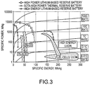
- FIG. 3 depicts a plot of specific energy, in Wh/kg (horizontal axis), verses specific power (vertical axis), in W/kg, for electrochemical energy storage devices and systems of the prior art and according to some embodiments of the present disclosure
- FIG. 4 depicts an electrochemical energy storage device and/or system according to some embodiments of the present disclosure
- FIG. 5 depicts a corrugated electrode of an electrochemical energy storage device and/or system according to some embodiments of the present disclosure
- FIG. 6A depicts an aluminum tab and a copper current collector according to some embodiment of the present disclosure
- FIG. 6B depicts an aluminum tab and a copper current collector according to some embodiment of the present disclosure
- FIG. 7A depicts a laminated electrochemical sub-cell according to some embodiments of the present disclosure
- FIG. 7B depicts a laminated electrochemical sub-cell according to some embodiments of the present disclosure
- FIG. 8A depicts a laminated electrochemical cell stack according to some embodiments of the present disclosure
- FIG. 8B depicts a laminated electrochemical cell stack according to some embodiments of the present disclosure
- FIG. 9 depicts a specific capacity, mAh/g, (horizontal axis) versus voltage, V, (vertical axis) plot of an electrochemical cell stack according to some embodiments of the present disclosure
- FIG. 10A depicts an electrochemical cell without channels and/or grooves according to some embodiments of the present disclosure
- FIG. 10B depicts an electrochemical cell with channels and/or grooves according to some embodiments of the present disclosure
- FIG. 10C depicts the interfacial contact between the corrugated electrodes and separator in an electrochemical cell according to some embodiments of the present disclosure
- FIG. 11A depicts a laser-ablated corrugated cathode showing the channels and/or grooves according to some embodiments of the present disclosure
- FIG. 11B depicts a laser-ablated corrugated anode according to some embodiments of the present disclosure
- FIG. 12 depicts a degree of electrolyte spreading and/or wetting for a corrugated electrode according to some embodiments of the present disclosure
- FIG. 13A depicts a degree of electrolyte spreading and/or wetting for a corrugated electrode according to some embodiments of the present disclosure
- FIG. 13B depicts a degree of electrolyte spreading and/or wetting for a corrugated electrode according to some embodiments of the present disclosure
- FIG. 13C depicts a degree of electrolyte spreading and/or wetting for a corrugated electrode according to some embodiments of the present disclosure
- FIG. 14A depicts a degree of electrolyte spreading and/or wetting for a corrugated electrode according to some embodiments of the present disclosure
- FIG. 14B depicts a degree of electrolyte spreading and/or wetting for a corrugated electrode according to some embodiments of the present disclosure
- FIG. 14C depicts a degree of electrolyte spreading and/or wetting for a corrugated electrode according to some embodiments of the present disclosure
- FIG. 15 depicts a degree of electrolyte spreading and/or wetting for a corrugated electrode according to some embodiments of the present disclosure
- FIG. 16A depicts a degree of electrolyte spreading and/or wetting for a corrugated electrode according to some embodiments of the present disclosure
- FIG. 16B depicts a degree of electrolyte spreading and/or wetting for a corrugated electrode according to some embodiments of the present disclosure
- FIG. 16C depicts a degree of electrolyte spreading and/or wetting for a corrugated electrode according to some embodiments of the present disclosure
- FIG. 17 depicts a plot of time, seconds, versus percentage height of height or area of a corrugated electrode according to various embodiments of the present disclosure
- FIG. 18 depicts a coated corrugated electrode according to some embodiments of the present disclosure.
- FIG. 19 depicts a plot of the specific capacity, mAh/g, (horizontal axis) versus voltage, V, (vertical axis) of an electrode according to some embodiments of the present disclosure
- FIG. 20 depicts a plot of the specific capacity, mAh/g, (horizontal axis) versus voltage, V, (vertical axis) of various electrochemical cell according to some embodiments of the present disclosure
- FIG. 21 depicts a laser-ablated electrode having channels and/or grooves and voids and/or apertures according to some embodiments of the present disclosure
- FIG. 22 depicts a laser-ablated electrode having channels and/or grooves and voids and/or apertures according to some embodiments of the present disclosure
- FIG. 23 depicts an electrochemical device or system according to an embodiment
- FIG. 24 depicts an electrochemical device or system according to an embodiment.
- Some embodiments of the present disclosure relate to an electrochemical system and/or device design architectures and methods of making those architectures. Some of those embodiments include electrochemical cell designs having one or more electrodes.
- FIG. 1 depicts an electrochemical component according to the present disclosure.
- the electrochemical component 100 comprises first and second oppositely polarized electrode 104 a and b , an electrolyte 108 a and b , a corrugated surface 112 a and b adjacent to each of the first and second electrodes 104 a and b , respectively, and the corresponding electrolyte 108 a and b , an optional current collector 116 a and b in electrical communication with each of the first and second electrodes 104 a and b , respectively, and an optional separator (or ion-permeable membrane) 120 interposed between the corrugated surfaces 112 a and b and electrolyte 108 a and b .
- the electrochemical component 100 can be a cathode or anode in an electrochemical energy storage device, such as a capacitor, supercapacitor or ultracapacitor or electric double-layer capacitor, battery, and the like.
- the corrugated surface 112 can have one or more of perforations, voids, apertures, cavities, holes, passages, channels, and/or grooves (individually or collectively a “corrugation feature”), and an ion (permeable, semi-permeable, or impermeable) separator between the electrodes can have one or more of perforations, voids, apertures, cavities, holes, passages, channels, and/or grooves (individually or collectively a “passage”).
- the corrugation features of the corrugated surface 112 are typically positioned on one or more surfaces of the one or more electrodes.
- the corrugation feature can be configured in the form of an interconnected network of corrugation features.
- the network of interconnected corrugation features can rapidly infuse an electrolyte throughout an electrode surface and separator due to the network of corrugation features.
- the average, median, or mode size e.g., dimension (such as diameter or width and/or height) of the corrugation features and/or passages can vary depending on the application, the average, median, or mode size(s) typically are larger than a micro-structure (e.g., larger than about 2 nm in any dimension).
- One or more of the average, median, or mode size(s) typically can be a meso-structure (e.g., in the range of from about 2 nm to about 50 nm).
- One or more of the average, median, or mode size(s) can be larger than a meso-structure (e.g., larger than 50 nm).
- the average, median, or mode size(s) of the corrugation features and/or passages is/are at least about 50 nm in any dimension.
- the average, median, or mode size(s) of the corrugation features and/or passages is/are at least about 1 ⁇ m in any dimension.
- the average, median, or mode size(s) of the corrugation features and/or passages is/are at least about 5 ⁇ m in any dimension.
- the average, median, or mode size(s) of the corrugation features and/or passages is/are at least about 10 ⁇ m in any dimension. Electrodes having the corrugated surface comprising one or more corrugation features can also be referred to as corrugated electrodes.
- the corrugated surface can have any pattern of corrugation features that provide more electrode contact surface area with the electrolyte.
- Patterns can include perforations, voids, apertures, cavities, and/or holes transverse to the electrolyte-contacting face of the surface, grooves or channels substantially parallel to the electrolyte-contacting face of the surface, and combinations thereof.
- Exemplary patterns include grooves or channels in a waffle-type pattern, channels radially diverging from cavities, cross-thatch pattern cavities or apertures via laser-ablated holes, and combinations thereof.
- the corrugated surface 112 can be formed by many techniques. For example, a laser ablation process can produce the corrugation features on the one or more electrodes. The laser ablation process can also be referred to as a machining process.
- the corrugated surface can be deposited as patterned thin film layers using a thin film technique such as chemical and/or physical deposition using masks and/or etchants to yield a layer having a desired pattern.
- a thin film technique such as chemical and/or physical deposition using masks and/or etchants to yield a layer having a desired pattern.
- an etchant reactive mask can be applied to the electrode surface before deposition and later removed by etching to weaken the overlying deposited material or an etchant resistant mask can be applied to the corrugated surface after deposition and the unmasked areas removed by the etchant to yield the desired pattern.
- the desired pattern can be yield by selective deposition of the thin film of the corrugated surface in selected (target) areas of the electrode surface to yield the
- the corrugated surface 112 can have the same or different chemical composition compared to the electrode 104 and be deposited, formed, or otherwise applied concurrently or sequentially with the electrode 104 material.
- the corrugated surface 112 can not only be separate from but also integral with the electrode 104 .
- the corrugated surface is formed from a material having an electrical conductivity at least as high as that of the electrode 104 and optional current collector 116 to enable free flow of electrons through the corrugated electrode and avoid collection of the current in the optional current collector 116 and electrode 104 .
- a capacitor using the corrugated surface 112 is typically a passive two-terminal electrical component used to store electrical energy temporarily in an electric field.
- the forms of practical capacitors vary widely, but all contain at least two electrical conductors (plates) (one or both of which can be a corrugated electrode) separated by a dielectric (i.e. an insulator that can store energy by becoming polarized).
- the conductors can be thin films, foils or sintered beads of metal or conductive electrolyte, etc.
- the non-conducting dielectric acts to increase the capacitor's charge capacity. Materials commonly used as dielectrics include glass, ceramic, plastic film, air, vacuum, paper, mica, and oxide layers.
- a capacitor stores energy in the form of an electrostatic field between its plates.
- a supercapacitor employing the corrugated surface 112 does not use the conventional solid dielectric of ordinary capacitors but rather uses electrostatic double-layer capacitance, electrochemical pseudocapacitance, or a combination of both.
- An exemplary electrostatic double-layer supercapacitor comprises positively and negatively charged electrochemical components 100 , each comprising a polarized collector 116 , electrode 104 , Helmholtz double layer (not shown), and electrolyte 108 having positive and negatively charged ions, and a common separator 120 separating the oppositely charged electrochemical components.
- the separation of charge is commonly of the order of a few ⁇ ngstroms (0.3-0.8 nm), which is generally much smaller than in a conventional capacitor.
- One or more of the electrochemical components 100 comprises a corrugated electrode.
- the electrostatic double-layer capacitor typically uses carbon electrodes or derivatives thereof with much higher electrostatic double-layer capacitance than electrochemical pseudocapacitance, achieving separation of charge in the Helmholtz double layer at the interface between the surface of the conductive electrode and electrolyte.
- the most commonly used electrode material for such supercapacitors is one or more of activated carbon (AC), carbon fibre-cloth (AFC), carbide-derived carbon (CDC), carbon aerogel, graphite (graphene), graphene and carbon nanotubes (CNTs).
- Pore sizes in carbons typically range from micropores (less than 2 nm) to mesopores (2-50 nm), but only micropores ( ⁇ 2 nm) contribute to pseudocapacitance.
- the separation of charge is of the order of a few ⁇ ngstroms (0.3-0.8 nm), which is generally much smaller than in a conventional capacitor.
- Another type of supercapacitors includes electrochemical pseudocapacitors employing metal oxide (e.g., transition metal oxides) or conducting polymer electrodes with a high amount of electrochemical pseudocapacitance.
- Oxides of transition metals including ruthenium (RuO 2 ), iridium (IrO 2 ), iron (Fe 3 O 4 ), manganese (MnO 2 ) or sulfides such as titanium sulfide (TiS 2 ) alone or in combination generate strong faradaic electron-transferring reactions combined with low resistance.
- Conducting polymers include polyaniline, polythiophene, polypyrrole and polyacetylene.
- Some supercapacitors include one or more of MnO 2 or a conducting polymer to form the second electrode (e.g., the cathode or positive electrode). Such electrodes can employ electrochemical doping or dedoping of the polymers with anions and cations.
- hybrid capacitors such as the lithium-ion capacitor
- Composite electrodes for hybrid-type supercapacitors are constructed from carbon-based material with incorporated or deposited pseudocapacitive active materials like metal oxides and conducting polymers.
- Carbon nanotubes can provide a backbone for a homogeneous distribution of metal oxide or electrically conducting polymers (ECPs), producing good pseudocapacitance and good double-layer capacitance.
- Carbon nanotube electrodes can be doped with a pseudocapacitive dopant as in lithium-ion capacitors.
- Supercapacitor corrugated electrodes are generally thin coatings applied and electrically connected to a conductive, metallic current collector.
- the electrolyte forms an ionic conductive connection between the oppositely charged electrodes, one or both of which can be corrugated electrodes.
- Typical electrolytes include a solvent and dissolved chemicals that dissociate into positive cations and negative anions, making the electrolyte electrically conductive.
- Aqueous electrolytes are commonly treated with acids such as sulfuric acid (H 2 SO 4 ), alkalis such as potassium hydroxide (KOH), or salts such as quaternary phosphonium salts, sodium perchlorate (NaClO 4 ), lithium perchlorate (LiClO 4 ) or lithium hexafluoride arsenate (LiAsF 6 ).
- acids such as sulfuric acid (H 2 SO 4 ), alkalis such as potassium hydroxide (KOH), or salts such as quaternary phosphonium salts, sodium perchlorate (NaClO 4 ), lithium perchlorate (LiClO 4 ) or lithium hexafluoride arsenate (LiAsF 6 ).
- Electrolytes can be based on organic solvents, such as acetonitrile, propylene carbonate, tetrahydrofuran, diethyl carbonate, ⁇ -butyrolactone and solutions with quaternaryammonium salts or alkyl ammonium salts such as tetraethylammonium tetrafluoroborate (N(Et) 4 BF 4 ) or triethyl (metyl) tetrafluoroborate (NMe(Et) 3 BF 4 ).
- organic solvents such as acetonitrile, propylene carbonate, tetrahydrofuran, diethyl carbonate, ⁇ -butyrolactone and solutions with quaternaryammonium salts or alkyl ammonium salts such as tetraethylammonium tetrafluoroborate (N(Et) 4 BF 4 ) or triethyl (metyl) tetrafluoroborate
- Separators can be very thin (a few hundredths of a millimeter) and very porous to the conducting ions to minimize electrostatic resistance. Separators are commonly chemically inert to protect the electrolyte's stability and conductivity. Separators can be, for example, open capacitor papers, nonwoven porous polymeric films like polyacrylonitrile or Kapton, woven glass fibers or porous woven ceramic fibres. Supercapacitors are typically polarized by design with asymmetric corrugated electrodes, or, for symmetric corrugated electrodes, by a potential applied during manufacture. As will be appreciated, supercapacitors can be wound or stacked in construction.
- a battery comprises an electrochemical cell having plural corrugated electrodes with external connections provided to power electrical devices.
- a battery When a battery is supplying power, its positive terminal is the cathode and its negative terminal is the anode.
- a battery can include plural pairs of oppositely charged electrodes with the number of pairs being related to the energy storage capacity of the battery.
- the electrochemical device 100 includes the first and second electrodes 104 a and b , connected in series by the conductive electrolyte 108 containing anions and cations. Each polarized first and second electrode 104 has only one facing corrugated surface 112 , while the other electrode surface is conventional or non-corrugated.
- the interior electrodes can have opposing corrugated surfaces to interact with an oppositely polarized electrode on either of its sides.
- the adjacent oppositely charged electrodes are electrically connected by one or more electrolytes 108 and separated by the separator 120 .
- a current collector 116 can be part of the electrode depending on electrode location in the battery.
- one oppositely charged electrode pair includes the negative, optionally corrugated, electrode, or the electrode to which anions (negatively charged ions) migrate, and the other electrode in the pair includes the positive, optionally corrugated, electrode to which cations (positively charged ions) migrate. Redox reactions power the battery.
- Cations are reduced (e.g., electrons are added) at the cathode during charging, while anions are oxidized (e.g., electrons are removed) at the anode during charging.
- anions are oxidized (e.g., electrons are removed) at the anode during charging.
- the electrodes do not physically touch each other, but are electrically connected by the electrolyte.
- Some cells use different electrolytes for each electrolyte 108 a and 108 b .
- the separator can allow ions to flow between opposing electrodes but prevent mixing of the electrolytes.
- the battery can be a primary battery, that irreversibly transforms chemical energy to electrical energy or a secondary battery that can be recharged, or have its chemical reaction substantially reversed, by supplying electrical energy to the cell.
- the battery can be a wet cell, or using a liquid electrolyte, or a dry cell, or using a paste electrolyte with sufficient moisture to enable the current to flow.
- the battery can be a reserve battery that is stored unassembled (e.g., unactivated and supplying no power) for a long period (e.g., years), and, when the battery is needed, it can be assembled by adding electrolyte and charged and ready to supply electrical energy.
- a battery can be activated by impact, such as a wreck of a vehicle or air plane or other type of impact: The acceleration breaks a capsule of electrolyte that activates the battery.
- the corrugated surface of the present disclosure can be employed in many types of electrochemical systems including galvanic cells, electrolytic cells, fuel cells, flow cells, and voltaic piles.
- the corrugated surface can be beneficial in primary, secondary or reserve battery chemistry including without limitation primary batteries such as zinc-carbon, zinc-chloride, alkaline (e.g., zinc manganese dioxide), nickel oxyhydroxide (e.g., zinc-manganese dioxide/nickel oxyhydroxide), lithium (e.g., lithium-copper oxide or Li—CuO, lithium-iron disulfide or LiFeS 2 , lithium-manganese dioxide or LiMnO 2 , lithium-carbon fluoride or Li—(CF) n , and lithium-chromium oxide or Li—CrO 2 ), mercury oxide, zinc-air, Zamboni pile, silver oxide (silver-zinc), and magnesium and secondary batteries such as NiCd, lead-acid, NiMH, NiZn, AgZn,
- the corrugated electrode can address current reserve battery shortcomings and alternatives to them.
- a lithium-based, chemical reserve battery is a non-limiting example of an electrochemical energy reserve system and/or device.
- the chemical reserve batteries using one or more corrugated electrodes can have tremendous potential to supplant currently utilized thermal, reserve batteries and alternative chemical reserve batteries that implement a liquid-based cathode.
- the chemical reserve batteries using one or more corrugated electrodes can offer up to more than ten times more energy, power, or combination thereof than conventional thermal reserve batteries. While not wishing to be bound by any theory, the increase in one or more of the energy and power of the chemical reserve batteries described herein is believed to be due to the utilization of the one or more high energy and power density of lithium based battery electrochemistry.
- solid-state, thin-film electrodes with a network of channels and cavities can permit the rapid infusion of electrolyte leading to rapid activation and rise times (projected milliseconds) independent of battery size.
- This disclosure is particularly beneficial to solid-state cathodes, rather than liquid based cathodes such as, Lithium sulfur dioxide (Li—SO 2 ), Lithium thionyl chloride (Li—SOCl 2 ) or Lithium sulfuryl chloride (Li—SO 2 Cl 2 ) that can pose serious operational and safety concerns.
- some embodiments of the present disclosure relate to chemical reserve batteries and methods of making those batteries.
- the electrochemical system design can include a hermetically sealed, laminated, bipolar, electrochemical battery configuration.
- the hermetically sealed, laminated, bipolar, electrochemical battery can be stored in a galvanic state capable of providing electrical current once activated with electrolyte.
- the ability to assemble the hermetically sealed, laminated, bipolar, electrochemical battery in a galvanic state without an electrolyte can achieve a shelf life of the electrochemical battery of about 30 years or more.
- the ability to assemble the hermetically sealed, laminated, bipolar, electrochemical battery in a galvanic state without an electrolyte can achieve a shelf life of the electrochemical battery of about 29 years or more.
- the ability to assemble the hermetically sealed, laminated, bipolar, electrochemical battery in a galvanic state without an electrolyte can achieve a shelf life of the electrochemical battery of about 28 years or more.
- the ability to assemble the hermetically sealed, laminated, bipolar, electrochemical battery in a galvanic state without an electrolyte can achieve a shelf life of the electrochemical battery of about 27 years or more.
- the ability to assemble the hermetically sealed, laminated, bipolar, electrochemical battery in a galvanic state without an electrolyte can achieve a shelf life of the electrochemical battery of about 26 years or more.
- the ability to assemble the hermetically sealed, laminated, bipolar, electrochemical battery in a galvanic state without an electrolyte can achieve a shelf life of the electrochemical battery of about 25 years or more.
- the ability to assemble the hermetically sealed, laminated, bipolar, electrochemical battery in a galvanic state without an electrolyte can achieve a shelf life of the electrochemical battery of about 24 years or more.
- the ability to assemble the hermetically sealed, laminated, bipolar, electrochemical battery in a galvanic state without an electrolyte can achieve a shelf life of the electrochemical battery of about 23 years or more.
- the ability to assemble the hermetically sealed, laminated, bipolar, electrochemical battery in a galvanic state without an electrolyte can achieve a shelf life of the electrochemical battery of about 22 years or more.
- the ability to assemble the hermetically sealed, laminated, bipolar, electrochemical battery in a galvanic state without an electrolyte can achieve a shelf life of the electrochemical battery of about 21 years or more.
- the ability to assemble the hermetically sealed, laminated, bipolar, electrochemical battery in a galvanic state without an electrolyte can achieve a shelf life of the electrochemical battery of about 20 years or more.
- the ability to assemble the hermetically sealed, laminated, bipolar, electrochemical battery in a galvanic state without an electrolyte can achieve a shelf life of the electrochemical battery of about 19 years or more.
- the ability to assemble the hermetically sealed, laminated, bipolar, electrochemical battery in a galvanic state without an electrolyte can achieve a shelf life of the electrochemical battery of about 18 years or more.
- the ability to assemble the hermetically sealed, laminated, bipolar, electrochemical battery in a galvanic state without an electrolyte can achieve a shelf life of the electrochemical battery of about 17 years or more.
- the ability to assemble the hermetically sealed, laminated, bipolar, electrochemical battery in a galvanic state without an electrolyte can achieve a shelf life of the electrochemical battery of about 16 years or more.
- the ability to assemble the hermetically sealed, laminated, bipolar, electrochemical battery in a galvanic state without an electrolyte can achieve a shelf life of the electrochemical battery of about 15 years or more.
- the ability to assemble the hermetically sealed, laminated, bipolar, electrochemical battery in a galvanic state without an electrolyte can achieve a shelf life of the electrochemical battery of about 14 years or more.
- the ability to assemble the hermetically sealed, laminated, bipolar, electrochemical battery in a galvanic state without an electrolyte can achieve a shelf life of the electrochemical battery of about 13 years or more.
- the ability to assemble the hermetically sealed, laminated, bipolar, electrochemical battery in a galvanic state without an electrolyte can achieve a shelf life of the electrochemical battery of about 12 years or more.
- the ability to assemble the hermetically sealed, laminated, bipolar, electrochemical battery in a galvanic state without an electrolyte can achieve a shelf life of the electrochemical battery of about 11 years or more.
- the ability to assemble the hermetically sealed, laminated, bipolar, electrochemical battery in a galvanic state without an electrolyte can achieve a shelf life of the electrochemical battery of about 10 years or more.
- the ability to assemble the hermetically sealed, laminated, bipolar, electrochemical battery in a galvanic state without an electrolyte can achieve a shelf life of the electrochemical battery of about 9 years or more.
- the ability to assemble the hermetically sealed, laminated, bipolar, electrochemical battery in a galvanic state without an electrolyte can achieve a shelf life of the electrochemical battery of about 8 years or more.
- the ability to assemble the hermetically sealed, laminated, bipolar, electrochemical battery in a galvanic state without an electrolyte can achieve a shelf life of the electrochemical battery of about 7 years or more.
- the ability to assemble the hermetically sealed, laminated, bipolar, electrochemical battery in a galvanic state without an electrolyte can achieve a shelf life of the electrochemical battery of about 6 years or more.
- the ability to assemble the hermetically sealed, laminated, bipolar, electrochemical battery in a galvanic state without an electrolyte can achieve a shelf life of the electrochemical battery of about 5 years or more.
- the ability to assemble the hermetically sealed, laminated, bipolar, electrochemical battery in a galvanic state without an electrolyte can achieve a shelf life of the electrochemical system of at least about from 5 to about 30 years.
- the ability to assemble the hermetically sealed, laminated, bipolar, electrochemical battery in a galvanic state without an electrolyte can achieve a shelf life of the electrochemical battery of at least about form 5 to about 29 years.
- the ability to assemble the hermetically sealed, laminated, bipolar, electrochemical battery in a galvanic state without an electrolyte can achieve a shelf life of the electrochemical battery of at least about form 5 to about 28 years.
- the ability to assemble the hermetically sealed, laminated, bipolar, electrochemical battery in a galvanic state without an electrolyte can achieve a shelf life of the electrochemical battery of at least about form 5 to about 27 years.
- the ability to assemble the hermetically sealed, laminated, bipolar, electrochemical battery in a galvanic state without an electrolyte can achieve a shelf life of the electrochemical battery of at least about form 5 to about 26 years.
- the ability to assemble the hermetically sealed, laminated, bipolar, electrochemical battery in a galvanic state without an electrolyte can achieve a shelf life of the electrochemical battery of at least about form 5 to about 25 years.
- the ability to assemble the hermetically sealed, laminated, bipolar, electrochemical battery in a galvanic state without an electrolyte can achieve a shelf life of the electrochemical battery of at least about form 5 to about 24 years.
- the ability to assemble the hermetically sealed, laminated, bipolar, electrochemical battery in a galvanic state without an electrolyte can achieve a shelf life of the electrochemical battery of at least about form 5 to about 23 years.
- the ability to assemble the hermetically sealed, laminated, bipolar, electrochemical battery in a galvanic state without an electrolyte can achieve a shelf life of the electrochemical battery of at least about form 5 to about 22 years.
- the ability to assemble the hermetically sealed, laminated, bipolar, electrochemical battery in a galvanic state without an electrolyte can achieve a shelf life of the electrochemical battery of at least about form 5 to about 21 years.
- the ability to assemble the hermetically sealed, laminated, bipolar, electrochemical battery in a galvanic state without an electrolyte can achieve a shelf life of the electrochemical battery of at least about form 5 to about 20 years.
- the ability to assemble the hermetically sealed, laminated, bipolar, electrochemical battery in a galvanic state without an electrolyte can achieve a shelf life of the electrochemical battery of at least about form 5 to about 19 years.
- the ability to assemble the hermetically sealed, laminated, bipolar, electrochemical battery in a galvanic state without an electrolyte can achieve a shelf life of the electrochemical battery of at least about form 5 to about 18 years.
- the ability to assemble the hermetically sealed, laminated, bipolar, electrochemical battery in a galvanic state without an electrolyte can achieve a shelf life of the electrochemical battery of at least about form 5 to about 17 years.
- the ability to assemble the hermetically sealed, laminated, bipolar, electrochemical battery in a galvanic state without an electrolyte can achieve a shelf life of the electrochemical battery of at least about form 5 to about 16 years.
- the ability to assemble the hermetically sealed, laminated, bipolar, electrochemical battery in a galvanic state without an electrolyte can achieve a shelf life of the electrochemical battery of at least about form 5 to about 15 years.
- the ability to assemble the hermetically sealed, laminated, bipolar, electrochemical battery in a galvanic state without an electrolyte can achieve a shelf life of the electrochemical battery of at least about form 5 to about 14 years.
- the ability to assemble the hermetically sealed, laminated, bipolar, electrochemical battery in a galvanic state without an electrolyte can achieve a shelf life of the electrochemical battery of at least about form 5 to about 13 years.
- the ability to assemble the hermetically sealed, laminated, bipolar, electrochemical battery in a galvanic state without an electrolyte can achieve a shelf life of the electrochemical battery of at least about form 5 to about 12 years.
- the ability to assemble the hermetically sealed, laminated, bipolar, electrochemical battery in a galvanic state without an electrolyte can achieve a shelf life of the electrochemical battery of at least about form 5 to about 11 years.
- the ability to assemble the hermetically sealed, laminated, bipolar, electrochemical battery in a galvanic state without an electrolyte can achieve a shelf life of the electrochemical battery of at least about form 5 to about 10 years.
- the ability to assemble the hermetically sealed, laminated, bipolar, electrochemical battery in a galvanic state without an electrolyte can achieve a shelf life of the electrochemical battery of at least about form 5 to about 9 years.
- the ability to assemble the hermetically sealed, laminated, bipolar, electrochemical battery in a galvanic state without an electrolyte can achieve a shelf life of the electrochemical battery of at least about form 5 to about 8 years.
- the ability to assemble the hermetically sealed, laminated, bipolar, electrochemical battery in a galvanic state without an electrolyte can achieve a shelf life of the electrochemical battery of at least about form 5 to about 7 years.
- the ability to assemble the hermetically sealed, laminated, bipolar, electrochemical battery in a galvanic state without an electrolyte can achieve a shelf life of the electrochemical battery of at least about form 5 to about 6 years.
- the rapid infusion and/or diffusion of the electrolyte throughout the corrugated electrode surface and inter-electrode spaces can decrease activation time for the chemical reserve battery using one or more corrugated electrodes.
- the rapid infusion and/or diffusion of the electrolyte throughout the corrugated electrode surface and inter-electrode spaces and optional ion separator passages are believed to decrease activation time for an electrochemical system and/or battery.
- the corrugation features and optional ion separator passages can rapidly infuse and/or diffuse an electrolyte throughout an electrode surface and inter-electrode spaces in no more than about five seconds.
- the corrugation features and optional ion separator passages can rapidly infuse and/or diffuse an electrolyte throughout an electrode surface and inter-electrode spaces in typically no more than about four seconds.
- the corrugation features and optional ion separator passages can rapidly infuse and/or diffuse an electrolyte throughout an electrode surface and inter-electrode spaces in typically no more than about three seconds.
- the corrugation features and optional ion separator passages can rapidly infuse and/or diffuse an electrolyte throughout an electrode surface and inter-electrode spaces typically in no more than about two seconds.
- the corrugation features and optional ion separator passages can rapidly infuse and/or diffuse an electrolyte throughout an electrode surface and inter-electrode spaces in no more than about 1.5 seconds.
- the corrugation features and optional ion separator passages can rapidly infuse and/or diffuse an electrolyte throughout an electrode surface and inter-electrode spaces in typically no more than about one second.
- the corrugation features and optional ion separator passages can rapidly infuse and/or diffuse an electrolyte throughout an electrode surface and inter-electrode spaces in typically no more than about 0.75 second.
- the corrugation features and optional ion separator passages can rapidly infuse and/or diffuse an electrolyte throughout an electrode surface and inter-electrode spaces in typically no more than about 0.5 second.
- the corrugation features and optional ion separator passages can rapidly infuse and/or diffuse an electrolyte throughout an electrode surface and inter-electrode spaces in typically no more than about 0.25 second.
- the corrugation features and optional ion separator passages can rapidly infuse and/or diffuse an electrolyte throughout an electrode surface and inter-electrode spaces in typically less than about one second.
- a chemical reserve battery using one or more corrugated electrodes can include one or both of a lithiated anode and a non-lithiated or partially lithiated cathode, either or both of which can be corrugated.
- the one or both of a lithiated anode and a non-lithiated or partially lithiated cathode can prime the chemical reserve battery using one or more corrugated electrodes, such as the electrochemical system, in a galvanic state (full charge state once the chemical reserve battery using one or more corrugated electrodes (the electrochemical system) is activated).
- Non-limiting examples of composition comprising the lithiated anode can be lithium, LiM (e.g., LiSi, LiAl, etc.) or addition to what is a commonly referred to as a stabilized lithium metal powder (SLMP) to graphite or other carbonaceous material or metal.
- LiM e.g., LiSi, LiAl, etc.
- SLMP stabilized lithium metal powder
- FIG. 2 depicts the internal components of a cell 250 for the chemical reserve battery comprising multiple stacked or wrapped electrodes 200 a - c in accordance with some embodiments of the present disclosure.
- Each electrode 200 includes negatively and positively charged first and second electrodes separated by a separator 220 .
- the separator 220 generally electronically isolates first and second electrodes 208 and 209 .
- the first separator 200 a electronically isolates the first and second electrodes 208 a and 209 a that are, respectively, an anode and a cathode.
- Each of the first and second electrodes 208 a and 209 b can have corrugated first and second electrode surfaces 212 a and 213 a having accompanying corrugation features.
- the chemical reserve battery using one or more corrugated electrodes has multiple separators 220 a, b, c , . . . electronically isolating alternatingly stacked anodes and cathodes.
- the first electrode 208 a has only one corrugated surface.
- the second electrode 209 a has opposing first and second surfaces, each of which can be corrugated as the second electrode 209 a is shared by the first and second separators 220 a,b . In the second electrode the second corrugated surface of the second electrode 209 a electrically communicates with the first corrugated surface of a first electrode 208 b .
- the third separator 220 c , the first electrode 208 b has an opposing second corrugated surface in electrical communication with a corrugated surface of a second electrode 209 c .
- the second electrode 209 c has only one corrugated surface.
- the external current collectors 208 a and 209 b each have an outer face that is not coated.
- Each of the first and second electrodes 208 and 209 in each of the electrochemical systems has a corresponding current collector 201 a - d and are separated by the respective separator 220 a - c.
- the exteriors of the first electrode 208 a and second electrode 209 b exteriors are composed of significantly thicker foils than the interior electrodes with tab leads arbitrarily shown on opposite sides of the system.
- the system is encompassed with a packaging material (not shown; which may be laminated or not lamintated) with matched apertures to the system.
- the current collectors can be ultrasonically welded in parallel.
- the first electrode 208 and/or corrugated surface 212 can comprise any electrically conductive material.
- Non-limiting examples of the first electrode 208 and/or corrugated surface 212 which acts as an anode, are carbon (e.g., graphite, activated carbon, hard carbon, or soft carbon), copper, silver, lithium, lithiated metal alloys (e.g. LiSi, LiSb, LiSn), lithiated metal oxides, aluminum, steel, and nickel.
- lithiated metal alloys e.g. LiSi, LiSb, LiSn
- first electrode 208 and/or corrugated surface 212 anodic materials are graphite, activated carbon, hard carbon, soft carbon, lithiated metal alloys (e.g.
- first electrode 208 and/or corrugated surface 212 anodic materials are graphite, carbon, copper, silver, lithium, aluminum, steel, and nickel.
- first electrode and/or corrugated surface 212 anodic materials are without limitation are graphite, activated carbon, hard carbon, soft carbon, lithiated metal alloys (e.g. LiSi, LiSb, LiSn) and lithiated metal oxides.
- the second electrode 209 and/or corrugated surface 212 can comprise any electrically conductive material.
- Non-limiting examples of the second electrode 209 and/or corrugated surface 212 which acts as a cathode, are lithium compounds and alloys.
- Non-limiting examples of the second electrode 209 and/or corrugated surface 212 material are lithium metal oxides, lithium metal phosphates, lithium chalcogenides and lithium metal alloys.
- the separator 220 can be any ion permeable material, such as but not limited to an ion permeable membrane, typically known those of skill in art of electrochemical energy storage devices.
- Suitable separator 220 materials can be without limitation nonwoven fibers (cotton, nylon, polyesters, glass), polymer films (polyethylene, polypropylene, poly (tetrafluoroethylene), polyvinyl chloride), and naturally occurring substances (rubber, asbestos, wood).
- an interior system 2400 of alternating or oppositely polarized electrodes is depicted.
- the pair comprises a first electrode 2404 and second electrode 2408 , each comprising a corresponding first or second corrugation surface 2412 and 2416 , respectively, and first or second electrolyte 2420 and 2424 , respectively, with an intervening separator 2428 .
- Each of the first and second electrodes 2404 and 2408 comprise plural first corrugation features 2440 passing through the depth or thickness of the corresponding electrode and each of the first and second corrugation surfaces 2412 and 2416 comprise plural first corrugation features 2432 passing from the corresponding first or second electrolyte through the depth or thickness of the surface to a surface of the corresponding electrode.
- each electrode can also have a first or second corrugation surface comprising first and second corrugation features, depending on the cell configuration.
- the separator 2428 has plural passages 2436 passing through the depth or thickness of the separator from the first to the second electrolyte.
- Corresponding ones of the first corrugation features 2440 in each of the first and second electrodes, first corrugation features 2432 in each of the first and second corrugation surfaces 2412 and 2416 , and the passages 2436 in the separator 2428 are axially aligned to provide continual flow paths for the electrolyte not only from the first electrode surface to the second electrode surface and vice versa but also through each of the first and second electrodes to adjacent electrode surfaces of other stacked or wrapped electrode pairs.
- the aligned flow pathways enable the electrolyte to rapidly contact the electrically charged surfaces of the electrodes, thereby providing current.
- the current collectors 201 associated with the cathodic second electrodes 209 of the battery are ultrasonically welded together in parallel.
- the exterior current collectors 201 a and 201 d can be composed of a single side coating (toward the interior of the battery) and a thicker current collector (about 100 ⁇ m for electrodes of aluminum or copper).
- the thicker collector can serve as a system current lead and increase robustness.
- electrodes can be a thin foil (such as, about 10 ⁇ m got copper or about 15 ⁇ m for aluminum) deposited on the corresponding current collector.
- the thicker system tab can be a thin foil with an active electrode material coated on both sides of the current collector.
- a battery can comprise any number of alternating electrode pairs, such as one, two, three, four, five, six, seven, eight, nine, ten, eleven, or twelve alternating pairs.
- the battery can comprise from about 1 to about 100 alternating electrode pairs, more generally from about 2 to about 100 alternating electrode pairs, more generally from about 4 to about 80 alternating electrode pairs, more generally from about 4 to about 60 alternating electrode pairs, more generally from about 6 to about 40 alternating electrode pairs, and even more generally from about 6 to about 12 alternating electrode pairs.
- the alternating electrode pairs can be in the form of laminated electrochemical electrodes.
- the laminated electrode pairs can be in a stacked arrangement.
- the laminated electrode pairs can be stacked in a bipolar configuration.
- the bipolar stacking of the laminated, electrode pairs can provide one or both of an efficient stacking and a higher voltage electrochemical cell. It can be appreciated that the bipolar, stacked, laminated electrode pairs can be lithium-based alternating electrode pairs.
- the bipolar stacking of the laminated electrode pairs can provide an electrochemical cell having a capacity from about 100 Ah to about 1 mAh.
- the bipolar stacking of the laminated electrode pairs can provide an electrochemical cell having a capacity from about 95 Ah to about 100 mAh.
- the bipolar stacking of the laminated electrode pairs can provide an electrochemical cell having a capacity from about 90 Ah to about 200 mAh.
- the bipolar stacking of the laminated electrode pairs can provide an electrochemical cell having a capacity from about 85 Ah to about 300 mAh.
- the bipolar stacking of the laminated electrode pairs can provide an electrochemical cell having a capacity from about 80 Ah to about 400 mAh.
- the bipolar stacking of the laminated electrode pairs can provide an electrochemical cell having a capacity from about 85 Ah to about 500 mAh.
- the bipolar stacking of the laminated electrode pairs can provide an electrochemical cell having a capacity from about 80 Ah to about 600 mAh.
- the bipolar stacking of the laminated electrode pairs can provide an electrochemical cell having a capacity from about 75 Ah to about 700 mAh.
- the bipolar stacking of the laminated electrode pairs can provide an electrochemical cell having a capacity from about 70 Ah to about 800 mAh.
- the bipolar stacking of the laminated electrode pairs can provide an electrochemical cell having a capacity from about 65 Ah to about 900 mAh.
- the bipolar stacking of the laminated electrode pairs can provide an electrochemical cell having a capacity from about 60 Ah to about 1.0 Ah.
- the bipolar stacking of the laminated electrode pairs can provide an electrochemical cell having a capacity from about 55 Ah to about 1.5 Ah.
- the bipolar stacking of the laminated electrode pairs can provide an electrochemical cell having a capacity from about 50 Ah to about 2 Ah.
- the bipolar stacking of the laminated electrode pairs can provide an electrochemical cell having a voltage from about 15 to about 400 V.
- the bipolar stacking of the laminated electrode pairs can provide an electrochemical cell having a voltage from about 16 to about 375 V.
- the bipolar stacking of the laminated electrode pairs can provide an electrochemical cell having a voltage from about 17 to about 350 V.
- the bipolar stacking of the laminated electrode pairs can provide an electrochemical cell having a voltage from about 18 to about 325 V.
- the bipolar stacking of the laminated sub-cells can provide an electrochemical cell having a voltage from about 19 to about 300 V.
- the bipolar stacking of the laminated electrode pairs can provide an electrochemical cell having a voltage from about 20 to about 275 V.
- the bipolar stacking of the laminated electrode pairs can provide an electrochemical cell having a voltage from about 21 to about 250 V.
- the bipolar stacking of the laminated electrode pairs can provide an electrochemical cell having a voltage from about 22 to about 225 V.
- the bipolar stacking of the laminated electrode pairs can provide an electrochemical cell having a voltage from about 23 to about 200 V.
- the bipolar stacking of the laminated electrode pairs can provide an electrochemical cell having a voltage from about 24 to about 175 V.
- the bipolar stacking of the laminated electrode pairs can provide an electrochemical cell having a voltage from about 25 to about 150 V.
- the bipolar stacking of the laminated electrode pairs can provide an electrochemical cell having a voltage from about 26 to about 125 V.
- the bipolar stacking of the laminated electrode pairs can provide an electrochemical cell having a voltage from about 27 to about 100 V.
- the bipolar stacking of the laminated electrode pairs can provide an electrochemical cell having a voltage from about 28 to about 75 V.
- the bipolar stacking of the laminated electrode pairs can provide an electrochemical cell having a voltage from about 28 to about 70 V.
- the corrugated electrodes can be used beneficially in many other battery configurations, including those discussed above.
- the battery can be configured as a cylindrical cell having electrodes wrapped at least partially around one another.
- Electrochemical batteries fabricated according to some of the embodiments of the present disclosure can have one or more of higher power and energy densities and the ability to operate over a wide temperature range and operating conditions than conventional reserve battery systems.
- FIG. 3 depicts predicted results for electrochemical systems fabricated according to some of the embodiments described herein.
- the electrochemical systems fabricated according to some of the embodiments described herein have increases between five and ten times (or increases between 500% and 1000%) in specific energy and increases of at least two times (or increases of about 200%) in specific power over the current state of art of reserve batteries, as exemplified in the Ragone plot. It is further believed that one or more of the specific energy and specific power of the current state of art of batteries and/or reserve batteries can be improved through the incorporation of one or more of the corrugated electrodes described herein in some of the embodiments.
- the reserve battery described herein in some embodiments are projected to have specific power greater than 9 kW/kg when fabricated in a high power format with specific energy approaching 100 Wh/kg (see Ragone plot of FIG. 20 ).
- the electrochemical systems are also believed to have a continuous specific power greater than about 5 kW/kg in this high power format.
- the electrochemical systems are also believed to have a pulse power of about 10 kW/kg in this high power format.
- the reserve batteries fabricated according to some of the embodiments described herein could deliver at a lower specific power of more than about 200 Wh/kg.
- reserve battery enhancements can include a reduction of one or more of the electrochemical cell weight and volume.
- the reserve battery weight reduction, compared to reserve batteries of the prior art can be about 400% or more.
- the electrochemical battery weight reduction, compared to reserve batteries of the prior art can be no more than about 400%.
- the reduction in the electrochemical battery volume can be about 300% or more, when compared to reserve batteries of the prior art.
- the reduction in the electrochemical battery volume can be no more than about 300%, when compared to reserve batteries of the prior art. It is further believed that one or more of the electrochemical batteries weight and volume of the current state of art of batteries and/or reserve batteries can be improved through the incorporation of one or more of the corrugated electrodes described herein in some of the embodiments.
- the storage temperature range of the electrochemical battery is from about ⁇ 60 to about 110 degrees Celsius. In some embodiments, the storage temperature range is from about ⁇ 58 to about 105 degrees Celsius. In some embodiments, the storage temperature range of the electrochemical battery is from about ⁇ 55 to about 102 degrees Celsius. In some embodiments, the storage temperature range of the electrochemical battery is from about ⁇ 54 to about 100 degrees Celsius. It is further believed that one or more of the storage temperature of the current state of art of battery and/or reserve batteries can be improved through the incorporation of one or more of the corrugated electrodes described herein in some of the embodiments. As will be appreciated, the storage temperature is extended due to the implementation of a reserve battery (not activated until utilization), not specifically due to the corrugated electrodes. Moreover, the storage temperature is extended compared to many traditional lithium systems.
- the operating temperature range of the electrochemical batteries is from about ⁇ 30 to about 100 degrees Celsius. In some embodiments, the operating temperature range of the electrochemical batteries is from about ⁇ 35 to about 95 degrees Celsius. In some embodiments, the operating temperature range of the electrochemical batteries is from about ⁇ 38 to about 92 degrees Celsius. In some embodiments, the operating temperature range of the electrochemical batteries is from about ⁇ 40 to about 90 degrees Celsius. It is further believed that the operating temperature of the current state of art of batteries and/or reserve batteries can be improved through the incorporation of one or more of the corrugated electrodes described herein in some of the embodiments of the present disclosure. As will be appreciated, the operational temperature is extended due to the implementation of a reserve battery (not activated until utilization), not specifically due to the corrugated electrodes. Moreover, the operational temperature is extended compared to many traditional lithium systems.
- the rise temperature during activation is less than about 0.1 degrees Celsius during activation. In some embodiments, the rise of the electrochemical battery is less than about 0 degrees Celsius during activation (that is the temperature after activation is less than the temperature prior to activation). In some embodiments, the rise temperature of the electrochemical battery is less than about 0.2 degrees Celsius during activation. In some embodiments, the rise temperature of the electrochemical battery is less than about 0.5 degrees Celsius during activation. In some embodiments, the rise temperature of the electrochemical battery is less than about 1 degree Celsius.
- the rise temperature of the electrochemical battery is less than about 1.5 degrees Celsius during activation. In some embodiments, the rise temperature of the electrochemical battery is less than about 2.0 degrees Celsius during activation. In some embodiments, the rise temperature of the electrochemical battery is less than about 2.5 degrees Celsius during activation. In some embodiments, the rise temperature of the electrochemical battery is less than about 3 degrees Celsius during activation. In some embodiments, the rise temperature of the electrochemical battery is less than about 5 degrees Celsius during activation. It can be appreciated that the battery is immediately and sustainable for years thereafter, if necessary. Furthermore, the activation process of the present disclosure eliminates the need to coordinate pyrotechnics with activation process. It is further believed that one or more of the specific energy and specific power of the current state of art of reserve batteries can be improved through the incorporation of one or more of the corrugated electrodes described herein in some of the embodiments of the present disclosure.
- An electrochemical battery fabricated according to some embodiments of the present disclosure can comprise solid-state systems.
- An electrochemical battery fabricated according to some embodiments of the present disclosure can have redundant electrical connections. It can be appreciated that one or both of the solid-state systems construction and the redundant electrical connections contained within the electrochemical batteries can make for a durable electrochemical battery that can withstand excess forces, such as vibrational forces. It is further believed that the durability of the current state of art of reserve batteries can be improved through the incorporation of one or more of the corrugated electrodes described herein in some of the embodiments of the present disclosure.
- Another performance enhancement observed in electrochemical batteries fabricated according to some of the embodiments of the present disclosure is the ease of construction of the electrochemical battery.
- the lithium polymer fabrication according to some embodiments of the present disclosure can be less laborious than the current state of the art thermal battery construction or liquid-based cathode reserve battery systems.
- the fabrication of the corrugated electrodes according to some embodiments of the present disclosure can be less laborious than the current state of art thermal battery construction, particularly the thermal batteries activated by pyrotechnics. It is further believed that the ease of construction of the current state of art of batteries and/or reserve batteries can be improved through the incorporation of one or more of the corrugated electrodes described herein in some of the embodiments of the present disclosure.
- Another performance enhancement observed in electrochemical batteries fabricated according to some of the embodiments of the present disclosure is the flexibility in the construction of the electrochemical battery.
- Some embodiments include flexibility in the planar footprint size of the electrochemical systems; such a degree of flexibility is not available within the current state of the art battery design.
- effectively any voltage and capacity can be constructed into a single rigid, hermetically sealed battery design, such design options are not currently available within the current state of the reserve battery design and fabrication.
- the corrugated electrodes can be tailored to fit activation times. It is further believed that the flexibility of design and fabrication of the current state of art of batteries and/or reserve batteries can be improved through the incorporation of one or more of the corrugated electrodes described herein in some of the embodiments of the present disclosure.
- Another performance enhancement observed in electrochemical batteries fabricated according to some of the embodiments of the present disclosure is the improved safety of the electrochemical battery.
- the lower operating temperatures of battery are generally safer to operate than the current state of art reserve batteries that typically require pyrotechnics for activation.
- current reserve batteries commonly generate excessive heat, while the electrochemical systems of the present disclose usually generate little, if any, excess heat. It is further believed that the safety of the current state of art of batteries and/or reserve batteries can be improved through the incorporation of one or more of the corrugated electrodes described herein in some of the embodiments of the present disclosure.
- Lithium electrochemical systems are commonly limited to voltages of from about 2 to about 5 volts depending on the cell chemistry and the electrodes need to be electrochemically isolated when placed in series connection.
- a bipolar electrochemical cell configuration is often prohibitive in traditional lithium batteries due to electrochemical oxidation of the current collectors at high potentials, which commonly leads to subsequent loss of the current collectors and battery failure. With the electrochemical battery of present disclosure the deleterious reaction is negligible due to the short time the cell is activated.
- An electrochemical battery in particular a bipolar electrochemical cell as described herein, is therefore not only applicable, but desired, to obtain a high voltage in a single battery that can be activated without cell isolation.
- the bipolar design also affords the same flexibility to increase capacity by adding additional electrodes to each cell.
- the bipolar battery can eliminate the need for multiple cell enclosures and electrolyte fill systems. Rather, a single hermetically sealed rigid container can house the high capacity, high voltage battery.
- the cell configuration can be based upon a traditional stacked planar electrode lithium electrochemical cell design.
- cell tabs can be oriented on opposite sides of the cell stack ( FIG. 1 ) to accommodate power, or along the same side to maximize energy density. It can also be appreciated that in some embodiments, the cell tabs can be oriented on one side or the other of the cell stack.
- the cell anodes and cathodes are generally stacked alternately.
- the electrochemical cell typically includes a thin multi-layer plastic laminate positioned between each of electrode pairs with matched apertures to the electrode apertures to allow for electrolyte permeation while isolating the electrode pairs from shorting through electrolyte.
- electrodes internal to the cell are ultrasonically welded in parallel. That is the cell tabs associated with the anodes of the electrochemical system stack are ultrasonically welded together in parallel.
- the chemical reserve battery 400 can have many different configurations.
- the reserve battery can comprise any number of cells composed of multiple electrode pairs, such as six (28V) or twelve (56V) high capacity cells electrically interconnected in a series configuration.
- multiple cells 412 a - c each cell 412 comprising alternating pairs of first and second electrodes 208 and 209 separated by a separator 220 , are electrically connected to one another.
- adjacent alternating electrode pairs are also separated by a separator 220 .
- No separator 220 is positioned between adjacent cells 412 .
- Each of the first and second electrodes in each cell 412 has at least one corrugated surface 212 .
- the outermost electrodes in any cell 412 can have only one corrugated surface 212 while those sandwiched between adjacent electrodes typically have opposing corrugated surfaces 212 on either side of the electrode.
- FIGS. 4-5 depict an embodiment of a corrugated surface 212 .
- the surface 212 comprises perforations, voids, apertures, cavities or holes 404 dispersed at selected intervals over the face of the corrugated electrode.
- the perforations, voids, apertures, cavities or holes 404 can pass partially or completely through the electrode and may or may not be aligned with one another through the stacked electrodes in each cell. Commonly, the perforations, voids, apertures, cavities or holes 404 pass completely through the electrodes positioned interiorly of the cell but not through the electrodes (such as electrode 208 a adjacent the negative lead 420 ) positioned exteriorly of the cell. Typically, they are aligned to enable the electrolyte to flow through the entire electrode stack.
- each corrugated surface comprises a network of interconnected channels or grooves 500 (denoted by the solid lines) to enable the electrolyte to flow from the perforations or holes or voids 404 into the channels or grooves 500 , thereby dispersing the electrolyte laterally over the face, not just longitudinally through the face of, the electrode.
- the sizes of the perforations, voids, apertures, cavities or holes 404 and channels or grooves 500 are large enough to enable atoms of the electrolyte to pass therethrough.
- Electrical interconnections amongst the stacked cells can be made by conductive structures 408 a - c connected with the various common types of electrodes in each cell 412 a - c .
- a first conductive structure 408 a is connected to each first electrode 208 a - c and a second conductive structure 408 b is connected to each second electrode 209 a - c (which are polarized oppositely to the first electrodes) such that the first and second conductive structures 408 a and b are electrically connected in parallel to the stacked electrodes;
- the first conductive structure 408 d is connected to each first electrode 208 a - c and the second conductive structure 408 c is connected to each second electrode 209 a - c (which are polarized oppositely to the first electrodes) such that the first and second conductive structures 408 d and c are electrically connected in parallel to the stacked electrodes;
- a first electrically conductive bridge 416 a connects the second conductive structure 408 b in the first cell 412 a to the first conductive structure 408 d in the second cell 412 b ;
- a second electrically conductive bridge 416 b connects the second conductive structure 408 c in the second cell 412 b to the first conductive structure 408 e in the third cell 412 c ; and so on to the next cell (not shown).
- a negative lead 420 is connected to the first conductive structure 408 a and a similar positive lead (not shown) is connected to the final second conductive structure in the last cell in the battery 400 .
- the first and second conductive structures 408 are connected to corresponding electrodes and to the conductive bridges 416 by ultrasonic welding or other suitable techniques. These ultrasonically welded together redundant tab leads form a durable redundancy within the electrochemical bipolar cell.
- the foregoing components are typically encapsulated in a rigid hermetically sealed enclosure (not shown).
- the rigid enclosure can comprise any material.
- the rigid enclosure can be a high strength plastic, a metal, or combination thereof.
- the rigid enclosure can be a structural support.
- the rigid enclosure can comprise a durable material. It can be appreciated that the rigid enclosure can hermetically seal the electrochemical energy storage device and/or system. Generally, the electrodes and separator of the electrochemical storage device and/or system can be hermetically sealed by the rigid enclosure.
- the activation of the battery includes a rapid infusion of an electrolyte into the battery.
- the infusion of the electrolyte into the battery includes one or more of rapid spreading and wetting of the electrode surfaces by flow of the electrolyte longitudinally through the electrode stack via through perforations or holes or voids 404 and laterally along the face of each corrugated electrode via the interconnected network of grooves or channels 500 .
- An advantage of the rapid spreading and/or wetting of the electrode surfaces by the electrolyte is that the electrochemical energy storage device and/or system can be activated and reach its desired voltage in typically less than about a second.
- Applications within the prior art generally require a short “priming” period and/or a readying stage that usually include providing heat or time for activation, which is not always possible and require periods exceeding a few seconds.
- a non-limiting example of activating a chemical reserve battery will be illustrated with a bipolar solid state lithium reserve battery.
- rapid activation of a bipolar lithium reserve battery can be by one or more of forced or passive diffusion of an electrolyte by flow of the electrolyte longitudinally through the electrode stack via through perforations, voids, apertures, cavities or holes 404 and laterally along the face of each corrugated electrode via the interconnected network of grooves or channels 500 .
- the corrugation features can form a network of orientated holes and/or channels and/or grooves having a pattern, such as but not limited to a symmetric pattern of corrugation features throughout one or more electrodes of the bipolar lithium reserve battery.
- Such electrode architectures generally achieve one or more of rapid spreading and wetting of the electrode surfaces by the electrolyte.
- the electrolyte flow is typically substantially unimpeded in all directions throughout the electrochemical energy storage device and/or system as the electrolyte rapidly spreads and wets the electrode surfaces; that is, the electrolyte flows along the electrode architecture substantially uniformly along the electrode face's x and y-axes through the corrugation feature network and the z-axis through the corrugation features.
- variation of the size and number of corrugation features within one or more of the network of the corrugation features can affect electrolyte flow within the electrochemical energy storage device and/or system.
- variation of the size and number of corrugation features within the corrugation features can affect electrolyte diffusion distance within the electrochemical energy storage device and/or system.
- the size and number of corrugation features within the one or more of the network of the corrugation features can affect the activation time to achieve total spreading and wetting of the electrode surfaces.
- Providing corrugation features on the active electrode surface can impact one or more of the energy and power density of the electrochemical energy storage device and/or system.
- at least about 0.001% of the electrically active surface area (e.g., the electrode surface area that interacts with the electrolyte to either reduce or oxidize a compound, ion or element) comprises or is part of a corrugation feature.
- at least about 0.01% of the electrically active surface area comprises or is part of a corrugation feature.
- at least about 0.1% of the electrically active surface area comprises or is part of a corrugation feature.
- at least about 0.25% of the electrically active surface area comprises or is part of a corrugation feature.
- At least about 0.5% of the electrically active surface area comprises or is part of a corrugation feature. In some embodiments, at least about 0.75% of the electrically active surface area comprises or is part of a corrugation feature. In some embodiments, at least about 1% of the electrically active surface area comprises or is part of a corrugation feature. In some embodiments, at least about 0.75% of the electrically active surface area comprises or is part of a corrugation feature. In some embodiments, at least about 5% of the electrically active surface area comprises or is part of a corrugation feature. In some embodiments, at least about 0.75% of the electrically active surface area comprises or is part of a corrugation feature. In some embodiments, at least about 0.75% of the electrically active surface area comprises or is part of a corrugation feature.
- At least about 10% of the electrically active surface area comprises or is part of a corrugation feature. In some embodiments, no more than about 1.5% of the electrically active surface area comprises or is part of a corrugation feature. In some embodiments, no more than about 2% of the electrically active surface area comprises or is part of a corrugation feature. In some embodiments, no more than about 3% of the electrically active surface area comprises or is part of a corrugation feature. In some embodiments, no more than about 4% of the electrically active surface area comprises or is part of a corrugation feature. In some embodiments, no more than about 5% of the electrically active surface area comprises or is part of a corrugation feature.
- no more than about 6% of the electrically active surface area comprises or is part of a corrugation feature. In some embodiments, no more than about 7% of the electrically active surface area comprises or is part of a corrugation feature. In some embodiments, no more than about 8% of the electrically active surface area comprises or is part of a corrugation feature. In some embodiments, no more than about 9% of the electrically active surface area comprises or is part of a corrugation feature. In some embodiments, no more than about 10% of the electrically active surface area comprises or is part of a corrugation feature. In some embodiments, no more than about 11% of the electrically active surface area comprises or is part of a corrugation feature.
- no more than about 12% of the electrically active surface area comprises or is part of a corrugation feature. In some embodiments, no more than about 13% of the electrically active surface area comprises or is part of a corrugation feature. In some embodiments, no more than about 14% of the electrically active surface area comprises or is part of a corrugation feature. In some embodiments, no more than about 15% of the electrically active surface area comprises or is part of a corrugation feature. In some embodiments, no more than about 16% of the electrically active surface area comprises or is part of a corrugation feature. In some embodiments, no more than about 17% of the electrically active surface area comprises or is part of a corrugation feature.
- no more than about 18% of the electrically active surface area comprises or is part of a corrugation feature. In some embodiments, no more than about 19% of the electrically active surface area comprises or is part of a corrugation feature. In some embodiments, no more than about 20% of the electrically active surface area comprises or is part of a corrugation feature. In some embodiments, no more than about 21% of the electrically active surface area comprises or is part of a corrugation feature. In some embodiments, no more than about 22% of the electrically active surface area comprises or is part of a corrugation feature. In some embodiments, no more than about 23% of the electrically active surface area comprises or is part of a corrugation feature.
- no more than about 24% of the electrically active surface area comprises or is part of a corrugation feature. In some embodiments, no more than about 25% of the electrically active surface area comprises or is part of a corrugation feature. In some embodiments, no more than about 26% of the electrically active surface area comprises or is part of a corrugation feature. In some embodiments, no more than about 27% of the electrically active surface area comprises or is part of a corrugation feature. In some embodiments, no more than about 28% of the electrically active surface area comprises or is part of a corrugation feature. In some embodiments, no more than about 29% of the electrically active surface area comprises or is part of a corrugation feature.
- no more than about 30% of the electrically active surface area comprises or is part of a corrugation feature. In some embodiments, no more than about 31% of the electrically active surface area comprises or is part of a corrugation feature. In some embodiments, no more than about 32% of the electrically active surface area comprises or is part of a corrugation feature. In some embodiments, no more than about 33% of the electrically active surface area comprises or is part of a corrugation feature. In some embodiments, no more than about 35% of the electrically active surface area comprises or is part of a corrugation feature. In some embodiments, no more than about 40% of the electrically active surface area comprises or is part of a corrugation feature.
- no more than about 45% of the electrically active surface area comprises or is part of a corrugation feature. In some embodiments, no more than about 50% of the electrically active surface area comprises or is part of a corrugation feature. In some embodiments, no more than about 55% of the electrically active surface area comprises or is part of a corrugation feature. In some embodiments, no more than about 60% of the electrically active surface area comprises or is part of a corrugation feature. In some embodiments, no more than about 65% of the electrically active surface area comprises or is part of a corrugation feature. In some embodiments, no more than about 70% of the electrically active surface area comprises or is part of a corrugation feature.
- no more than about 75% of the electrically active surface area comprises or is part of a corrugation feature. In some embodiments, no more than about 80% of the electrically active surface area comprises or is part of a corrugation feature. In some embodiments, no more than about 90% of the electrically active surface area comprises or is part of a corrugation feature. In some embodiments, no more than about 92% of the electrically active surface area comprises or is part of a corrugation feature. In some embodiments, no more than about 94% of the electrically active surface area comprises or is part of a corrugation feature. In some embodiments, no more than about 96% of the electrically active surface area comprises or is part of a corrugation feature.
- no more than about 98% of the electrically active surface area comprises or is part of a corrugation feature. In some embodiments, no more than about 99% of the electrically active surface area comprises or is part of a corrugation feature. In some embodiments, no more than about 100% of the electrically active surface area comprises or is part of a corrugation feature.
- the number of corrugation features per square unit of the active surface area can be substantially constant or variable over the active surface area.
- the number of corrugation features per square unit of the active surface area is substantially constant while with reference to the corrugated electrode of FIG. 21 the number of corrugation features per unit square unit of the active surface area is variable over the active surface area. More specifically, the number of corrugation features per square unit of the active surface in the corrugated electrode of FIG. 21 increase near perforations, voids, apertures, holes, or cavities for accelerated wetting by the electrolyte and decreases at distance away from the perforations, voids, apertures, holes, or cavities to substantially maximize energy density.
- the dimensions of the grooves and/or channels can vary depending on the application.
- the grooves and/or channels can have an average, mean and/or mode width or depth of at least about 5 ⁇ m.
- the grooves and/or channels can have an average, mean and/or mode width or depth of at least about 7 ⁇ m.
- the grooves and/or channels can have an average, mean and/or mode width or depth at least about 9 ⁇ m.
- the grooves and/or channels can have an average, mean and/or mode width or depth of at least about 10 ⁇ m.
- the grooves and/or channels can have an average, mean and/or mode width or depth of at least about 12 ⁇ m.
- the grooves and/or channels can have an average, mean and/or mode width or depth of at least about 14 ⁇ m.
- the grooves and/or channels can have an average, mean and/or mode width or depth of at least about 15 ⁇ m.
- the grooves and/or channels can have an average, mean and/or mode width or depth of at least about 16 ⁇ m.
- the grooves and/or channels can have an average, mean and/or mode width or depth of at least about 18 ⁇ m.
- the grooves and/or channels can have an average, mean and/or mode width or depth of at least about 20 ⁇ m.
- the grooves and/or channels can have an average, mean and/or mode width or depth of no more than about 30 ⁇ m.
- the grooves and/or channels can have an average, mean and/or mode width or depth of no more than about 35 ⁇ m.
- the grooves and/or channels can have an average, mean and/or mode width or depth of no more than about 40 ⁇ m.
- the grooves and/or channels can have an average, mean and/or mode width or depth of no more than about 45 ⁇ m.
- the grooves and/or channels can have an average, mean and/or mode width or depth of no more than about 50 ⁇ m.
- the grooves and/or channels can have an average, mean and/or mode width or depth of no more than about 55 ⁇ m.
- the grooves and/or channels can have an average, mean and/or mode width or depth of no more than about 60 ⁇ m.
- the grooves and/or channels can have an average, mean and/or mode width or depth of no more than about 65 ⁇ m.
- the grooves and/or channels can have an average, mean and/or mode width or depth of no more than about 70 ⁇ m.
- the grooves and/or channels can have an average, mean and/or mode width or depth of no more than about 80 ⁇ m.
- the grooves and/or channels can have an average, mean and/or mode width or depth of no more than about 90 ⁇ m.
- the grooves and/or channels can have an average, mean and/or mode width or depth of no more than about 100 ⁇ m.
- the grooves and/or channels can have an average, mean and/or mode width or depth of no more than about 200 ⁇ m.
- the grooves and/or channels can have an average, mean and/or mode width or depth of no more than about 300 ⁇ m.
- the grooves and/or channels can have an average, mean and/or mode width or depth of no more than about 400 ⁇ m.
- the grooves and/or channels can have an average, mean and/or mode width or depth of no more than about 500 ⁇ m.
- the grooves and/or channels can have an average, mean and/or mode width or depth of no more than about 600 ⁇ m.
- the grooves and/or channels can have an average, mean and/or mode width or depth of no more than about 700 ⁇ m.
- the grooves and/or channels can have an average, mean and/or mode width or depth of no more than about 800 ⁇ m.
- the grooves and/or channels can have a width or depth of no more than about 900 ⁇ m.
- the grooves and/or channels can have an average, mean and/or mode width or depth of no more than about 1 mm.
- the perforations, voids, apertures, holes or cavities can have an average, mean and/or mode diameter of at least about 1 ⁇ m.
- the perforations, voids, apertures, holes or cavities can have an average, mean and/or mode diameter of at least about 20 ⁇ m.
- the perforations, voids, apertures, holes or cavities can have an average, mean and/or mode diameter of at least about 50 ⁇ m.
- the perforations, voids, apertures, holes or cavities can have an average, mean and/or mode diameter of at least about 100 ⁇ m.
- the perforations, voids, apertures, holes or cavities can have an average, mean and/or mode diameter of at least about 150 ⁇ m.
- the perforations, voids, apertures, holes or cavities can have an average, mean and/or mode diameter of at least about 200 ⁇ m.
- the perforations, voids, apertures, holes or cavities can have an average, mean and/or mode diameter of no at least about 250 ⁇ m.
- the perforations, voids, apertures, holes or cavities can have an average, mean and/or mode diameter of at least about 300 ⁇ m.
- the perforations, voids, apertures, holes or cavities can have an average, mean and/or mode diameter of at least about 350 ⁇ m.
- the perforations, voids, apertures, holes or cavities can have an average, mean and/or mode diameter of at least about 400 ⁇ m.
- the perforations, voids, apertures, holes or cavities can have an average, mean and/or mode diameter of at least about 425 ⁇ m.
- the perforations, voids, apertures, holes or cavities can have an average, mean and/or mode diameter of at least about 450 ⁇ m.
- the perforations, voids, apertures, holes or cavities can have an average, mean and/or mode diameter of at least about 475 ⁇ m.
- the perforations, voids, apertures, holes or cavities can have an average, mean and/or mode diameter of at least about 500 ⁇ m.
- the perforations, voids, apertures, holes or cavities can have an average, mean and/or mode diameter of at least about 525 ⁇ m.
- the perforations, voids, apertures, holes or cavities can have an average, mean and/or mode diameter of at least about 550 ⁇ m.
- the perforations, voids, apertures, holes or cavities can have an average, mean and/or mode diameter of at least about 575 ⁇ m.
- the perforations, voids, apertures, holes or cavities can have a diameter of at least about 600 ⁇ m.
- the perforations, voids, apertures, holes or cavities can have an average, mean and/or mode diameter of at least about 625 ⁇ m.
- the perforations, voids, apertures, holes or cavities can have an average, mean and/or mode diameter of at least about 700 ⁇ m.
- the perforations, voids, apertures, holes or cavities can have an average, mean and/or mode diameter of no more than about 50 mm.
- the perforations, voids, apertures, holes or cavities can have an average, mean and/or mode diameter of no more than about 45 mm.
- the perforations, voids, apertures, holes or cavities can have an average, mean and/or mode diameter of no more than about 40 mm.
- the perforations, voids, apertures, holes or cavities can have an average, mean and/or mode diameter of no more than about 35 mm.
- the perforations, voids, apertures, holes or cavities can have a diameter of no more than about 30 mm.
- the perforations, voids, apertures, holes or cavities can have an average, mean and/or mode diameter of no more than about 25 mm.
- the perforations, voids, apertures, holes or cavities can have an average, mean and/or mode diameter of no more than about 20 mm.
- the perforations, voids, apertures, holes or cavities can have an average, mean and/or mode diameter of no more than about 15 mm.
- the perforations, voids, apertures, holes or cavities can have an average, mean and/or mode diameter of no more than about 14 mm.
- the perforations, voids, apertures, holes or cavities can have an average, mean and/or mode diameter of no more than about 13 mm.
- the perforations, voids, apertures, holes or cavities can have an average, mean and/or mode diameter of no more than about 12 mm.
- the perforations, voids, apertures, holes or cavities can have an average, mean and/or mode diameter of no more than about 10 mm.
- the perforations, voids, apertures, holes or cavities can have an average, mean and/or mode diameter of no more than about 9 mm.
- the perforations, voids, apertures, holes or cavities can have an average, mean and/or mode diameter of no more than about 8 mm.
- the perforations, voids, apertures, holes or cavities can have an average, mean and/or mode diameter of no more than about 7 mm.
- the perforations, voids, apertures, holes or cavities can have an average, mean and/or mode diameter of no more than about 6 mm.
- the perforations, voids, apertures, holes or cavities can have an average, mean and/or mode diameter of no more than about 5 mm.
- the perforations, voids, apertures, holes or cavities can have an average, mean and/or mode diameter of no more than about 4 mm.
- the perforations, voids, apertures, holes or cavities can have an average, mean and/or mode diameter of no more than about 3 mm.
- the perforations, voids, apertures, holes or cavities can have an average, mean and/or mode diameter of no more than about 2 mm.
- the perforations, voids, apertures, holes or cavities can have an average, mean and/or mode diameter of no more than about 1 mm.
- the number and physical size of the perforation features can affect one or more of the energy, power density and activation time of the electrochemical energy storage device and/or system. It is believed that groove and/or channel widths of about 100 nm to about 250 ⁇ m can impart unintuitive properties to one or more of the energy, power density and activation time of the electrochemical energy storage device and/or system. In particular, the Reynolds number (which compares the effect of momentum of a fluid to the effect of viscosity) can become very low. As such, the electrolyte will not necessarily flow and mix in the traditional sense. Rather, the electrolyte will follow the physics of microfluidic flow and transport can be dominated by molecular diffusion.
- electrolyte flow regimes will generally follow one or more of creeping flow, potential flow, pressure driven flow, or more combination thereof. It is therefore expected that electrolyte flow and activation time will be likely influenced of Debye length (e.g., charge carrier electrostatic effects on the channel and/or groove flows), friction losses (Darcy-Weisbach equation) and Reynolds number.
- Debye length e.g., charge carrier electrostatic effects on the channel and/or groove flows
- friction losses Darcy-Weisbach equation
- Reynolds number Reynolds number of Reynolds number of the effects can be understood using a fully developed Navier-Stokes Equation shown below (assuming incompressible, Newtonian fluids):
- v flow velocity
- ⁇ fluid density
- f pressure force due to pressure head
- f friction force due to frictional losses
- f volume body forces acting on the fluid.
- a viscosity-driven response of microfluidic flow could impede the one or more of rapid spreading and wetting of the electrode surfaces by the electrolyte.
- the physical size of the channel network should be generally minimized.
- some embodiments of the present disclosure can include electrodes having any shape.
- the electrodes can have a shape generally resembling a rectangular box.
- the electrodes can have a shape generally resembling a cylinder.
- the electrodes can have a shape generally resembling one of an arch, curve, concaved, convex, crescent, or dome.
- the electrochemical energy storage device and/or system can have any shape.
- the electrochemical energy storage device and/or system can have a shape generally resembling a rectangular box.
- the electrochemical energy storage device and/or system can have a shape generally resembling a cylinder.
- the electrochemical energy storage device and/or system can have a shape generally resembling one of an arch, curve, concaved, convex, crescent, or dome.
- an activation mechanism can be any suitable activation mechanism.
- Non-limiting examples of possible activation mechanisms can include manual, automated, mechanical, electrical, hydraulic, and any combination thereof.
- the electrochemical energy storage device and/or system is/are devoid of the electrolyte.
- the electrochemical energy storage device and/or system electrolyte comprise one or more electrolyte input ports.
- the one or more inputs are usually in fluid communication with electrolyte.
- the electrolyte is typically stored in one of an electrolyte reservoir, pouch, tank, container, receptacle, or such.
- the one of the electrolyte reservoir, electrolyte pouch, electrolyte tank, electrolyte container, electrolyte receptacle, or such is in fluid communication with the one or more electrolyte input ports.
- the activation mechanism can include the step of transporting the electrolyte through an input line from the one of an electrolyte reservoir, pouch, tank, container, receptacle to the one or more electrolyte input ports.
- the activation mechanism can include introducing the electrolyte through the one or more electrolyte input ports into the electrochemical energy storage device and/or system.
- the activation mechanism can include after the introduction of the electrolyte into the electrochemical energy storage device and/or system the step of one or more of spreading and wetting the surfaces of the electrodes with the electrolyte.
- the electrochemical energy storage device and/or system can be constructed in an annular design to allow for a spring activated burst disc as with many other chemical reserve systems, or constructed in a prismatic block with an actuated piston pushing electrolyte into the cell, as well as many other possibilities. Due to the elevated operating temperatures, thermal batteries require immediate use after activation, but there is no need to coordinate activation with the actual use of the electrochemical energy storage device and/or system according to some of the embodiments of the present disclosure.
- the electrochemical storage device and/or system can be activated from one of less than a second, a second, to seconds, minutes, hours, or even days, to weeks, or months prior to use, without degradation or adverse effects. Furthermore, the electrochemical energy storage device and/or system can be activated during a high g-force event or other process and/or method of activation.
- Some embodiments of the present disclosure include texturing or patterning of an electrode.
- texturing or patterning of one or more electrodes of an electrochemical energy storage device and/or system can be done by a laser ablation process.
- the ablation can be by a high intensity pulsed laser.
- the laser can be typically coupled to a three-axis scanhead.
- the laser ablation can form the perforation features on the electrode.
- the perforation features can form a network of one or more orientated channels and/or grooves having a pattern on the electrode.
- the ablation can form a symmetric pattern of perforations, voids, apertures, cavities and/or holes on the electrode.
- the laser ablation can comprise a process of removing material from a solid (or occasionally liquid) surface by irradiating it with a laser beam.
- the ablation is a laser cutting process utilizing high intensity, fast moving beams with a small spot size.
- the laser ablation process generally comprises one or more of an optical beam scanning systems and a high brightness laser that can provide a highly efficient method of beam delivery.
- the laser ablation process can comprise galvanometer scanner technology.
- the galvanometer scanner technology can include high-performance rotary motors that produce high dynamic beam deflection.
- the low mass and inertia of the laser ablation systems can enable high scanning speeds (typically of more than about 15 m/s) and acceleration (generally of up to about 10 g).
- the scanning speed is commonly about 2 m/s or more. With automation of the laser, the scanning speed can be about 5 m/s or more.
- the scanning speed for cutting the one or more of the channels and/or grooves can be up to about 15 m/s. Any size electrode with any number of holes and channels and/or grooves can therefore be cut with high quality in less than a second ensuring a path to processing while minimizing cost.
- the electrode can be cut by one or more of combination of very high energy densities (usually of about 10 8 W/cm 2 ) in a very small laser spot (generally of no more than about 20 ⁇ m) with very high speed beam movement.
- the laser ablation process generally does not require any cutting gas as the melt in the cut kerf is partially vaporized and partially ejected by very high vapor pressure under extreme conditions of temperature and melt pool dynamics. Costly dies that hindered flexibility and require substantial maintenance are not required, and cut quality is improved in the laser ablation process.
- Some of the advances of laser ablation over die cut are one of more of: die cutting not amenable to rapid, scalable design changes, whereas laser ablation has a small footprint and is amenable to rapid prototyping and design changes; die cutting generally produces one or more of distinct edge debris, burrs, shards, and poor tolerance cuts, whereas laser ablation generally produces minimal edge debris, heat effected zone and scalloping with exceptional tolerances; die cutting is generally considered a high maintenance process, whereas laser ablation is commonly considered to be a low maintenance process; and die cutting is considered to have low reliability, whereas laser ablation is considered to have a high degree of reliability.
- laser ablation of electrodes can have the one or more of the following advantages: low cost fully automated cutting process; lower production cost; high throughput with maximum electrode cutting speeds from about 4 to about 5 m/s; -channels and/or grooves and holes cut at speeds approaching 15 m/s; unsurpassed cut/grooving quality with precision and accuracy exceeding stamped processes and other remote laser cutting operations; no geometrical design constraints to electrode size, cutouts and channels and/or grooves; maximum size of electrode restricted by image field size (of about 300 mm or more in one or more of length and width) of scanner which is often much larger than a lithium electrode footprint; flexible and quick footprint modification; durable, robust, nearly maintenance free system; straightforward integration of cutting system into production (process any standard electrode roll for cutting); and projected fully automated system to function at speeds of one of more than about 10 electrodes/min, of about 20 electrodes/min, of about 30 electrodes/min, of about 40 electrodes/min, of about 50 electrodes/min, of about 60 electrodes/min, of about 70 electrodes/min, of about
- Some embodiments of the present disclosure include laminated electrochemical cell assemblies.
- the laminated electrochemical cell assemblies can be laminated by a process that includes one or more of heat and pressure.
- the laminated electrochemical cell assemblies have increased durability. That is, laminated electrochemical cell assemblies generally do not fail, that is they usually successfully pass tests that mimic high gravitational-force accelerations. Lamination of the electrochemical cell assembly can mitigate this phenomenon.
- the lamination of the electrochemical cell assembly can include a separator containing a melt polymer (such as for example a melt polymer from CELGARD INC.TM) that serves to adhere the electrode to the separator. Adhering the electrode to the separator with an adhesive, such as with hot melt polymeric material, can laminate the electrochemical cell assembly.
- the laminating of the electrochemical cell assembly can maintain the contact of electrode and separator under high gravitational-force accelerations. In other words, the laminating of the electrochemical cell assembly can increase the durability of the cell assembly.
- High voltage bipolar prismatic pouch cells were fabricated and demonstrated electrochemically as set forth in the examples below.
- FIGS. 6A, 6B, 7A and 7B show a single laminated bipolar electrochemical cell before ( FIG. 6A ) and after packaging ( FIG. 6B ) having a 100 ⁇ m aluminum tab and a copper current collector prior to ( FIG. 7A ) and after being adhered to together ( FIG. 7B ) to form an electrochemical cell.
- the electrochemical cells can be arranged in series, FIG. 8A shows three electrochemical cels in series to form an electrochemical battery ( FIG. 8B ).
- the electrochemical performance of the three cells stacked in series and as a battery is depicted in FIG. 9 .
- the stacked cells are comprised of a graphite//LNMO electrochemical couple.
- the battery had a potential of 13.84 V and produced a capacity of 16 mAh.
- an electrochemical bi-cell containing one cathode and one anode with a separator between the electrodes was laminated.
- the separator comprised a polyspun polyvinylidene fluoride (PVDF) coated polyolefin separator from CELGARD INC®.
- PVDF polyspun polyvinylidene fluoride
- the electrodes and separator were assembled for intimate contact with no gaps in adhesion. This assembly represented a baseline for continued development of increased durability and robustness thereafter. Electrodes with and without channels and/or grooves exhibited excellent adhesion to the interfacial surface.
- FIGS. 10A-B depict laminated electrochemical bi-cells laminated without (left) and with (middle) channels and/or grooves. The electrochemical bi-cell on the right held in an upright position shows the interfacial contact between the electrodes and separator.
- FIGS. 11A-B depict on the left ( FIG. 11A ) a laser-ablated cathode and on the right ( FIG. 11B ) a laser-ablated anode, each having micro-channels and/or micro-grooves and cavities.
- FIG. 11A is an enlargement of laser-ablated cathode showing micro-channels and/or micro-grooves and apertures and voids.
- the anode and cathode were prepared from 24 cm 2 sheet of graphite coated onto a copper substrate and LNMO cathode coated onto aluminum substrate, respectively.
- micro-channels and/or micro-grooves and apertures and/or voids were formed by high speed laser ablation of the sheet.
- the micro-channels were cut at speeds of up to 2 m/s.
- Electrolyte diffusion rates for corrugated and non-corrugated electrodes as well as laminated cell stacks were determined.
- the electrolyte diffusion rates showed rapid electrolyte diffusion within the laminated stacked cells.
- the evaluations involved placing an electrode stack or stacked electrodes within an electrochemical energy storage device and/or system or a series of stacked electrode pairs in an electrolyte bath and monitoring the wicking rate.
- Electrolyte diffusion rates were determined for electrodes lacking micro-channels and/or micro-grooves and for electrodes having different types of micro-channels and/or micro-grooves.
- FIG. 12 depicts the degree of electrolyte wicking for an electrode lacking, that is devoid of, any micro-channels and/or micro-grooves.
- the horizontal line drawn across the electrode shows the level of electrolyte wicking after 300 seconds of emersion of the electrode edge in the electrolyte.
- the horizontal line was substantially at about the line where the electrode contacted the electrolyte. Hence, the electrolyte was not substantially wicked, if any, by the electrode lacking, that is electrode devoid of micro-channels and/or micro-grooves.
- FIGS. 13A-B and 14 A-C depict the degree of electrolyte wicking for electrodes having micro-channels and/or micro-grooves.
- the horizontal lines drawn across the electrodes, going from left to right, are height that the electrolyte wicked after 30, 60 and 300 seconds immersion in the electrolyte, respectively.
- micro-channels and/or micro-grooves of the electrode of FIG. 13A (left image) and 13 B (right image) were 4 mm spaced corrugations, and the electrolyte migration was dispersed laterally with time as electrolyte was directed along the 4 mm spaced micro-channel and/or micro-groove corrugations.
- 14A left image
- 14 B middle image
- 14 C right image
- the electrolyte wicking for the electrode having 1 mm spaced micro-channel and/or micro-groove corrugations the electrolyte wicked along the entire width of electrode.
- electrolyte migration proceeded along the entire width of electrode due to closer spacing of the 1 mm micro-channels and/or micro-grooves, compared to 4 mm spaced micro-channels and/or micro-grooves.
- FIG. 15 shows electrolyte wicking characteristics, shown by the line drawn across the laminated cell stack lacking (that is, devoid of) micro-channels and/or micro-grooves (in the form of horizontal lines and vertical lines laid out in a grid- or checker-board pattern). Electrolyte wicking was not observed after 300 seconds of immersion in the electrolyte.
- FIGS. 16A-16C show electrolyte wicking for a laminated cell stack above an electrolyte bath.
- the electrodes of the laminated cell pack have laser-fabricated micro-channels and/or micro-grooves (in the form of horizontal lines 1600 and vertical lines 1604 laid out in a grid- or checker-board pattern) spaced 1 mm apart micro-channel and/or micro-groove corrugations.
- the lines drawn across the laminated cell stack show the degree of electrolyte migration into the laminated cell pack after 30 (left), 60 (middle), and 300 seconds (right) immersion of the laminated cell stack in the electrolyte.
- the presence of micro-channels and/or micro-grooves resulted in a profound effect on electrolyte migration and/or wicking rate.
- a destructive physical analysis of the laminated cell stack confirmed that electrolyte migrated more than about half-way up the length of the stack on both the interior and exterior of the stack.
- Electrolyte migration was characterized by referencing the electrolyte migration front to the overall height or area of the electrode. Results for the various configurations are shown in FIG. 24 . The electrolyte migration rates were observed to be much more rapid when the micro-channels and/or micro-grooves were present. Further, the electrodes having corrugated micro-channels and/or micro-grooves had a more complete or total wetting of the electrode by the electrolyte throughout the electrolyte migration than the electrode lacing any micro-channels and/or micro-grooves or electrodes having non-corrugated or more greatly spaced micro-channels and/or micro-grooves.
- FIG. 17 depicts wetting profiles for various micro-channel and/or micro-groove configurations: an electrode with 4 mm spaced micro-channels and/or micro-grooves (lines 1708 and 1712 with diamond markers representing percentage of overall area and square markers representing percentage of overall height of electrolyte migration); an electrode with 1 mm spaced micro-channels and/or micro-grooves (line 1704 representing percentages for overall height and area of electrolyte migration); and cell stack with 1 mm spaced micro-channels and/or micro-grooves on all electrodes of the cell stack (line 1700 representing percentages of overall height and area of electrolyte migration).
- the initial rate of electrolyte migration height was observed to be similar for both the 4 mm and 1 mm spaced micro-channel and/or micro-groove corrugations.
- the entire width of the electrode was observed to be wet with the 1 mm spaced micro-channel and/or micro-groove corrugations whereas the electrodes with the 4 mm spaced micro-channel and/or micro-groove corrugations wetted primarily along the micro-channel and/or micro-groove corrugations and the electrolyte did not appear to migrate much beyond the immediate region of the micro-channel and/or micro-groove corrugations.
- the single electrode tests and electrodes in the laminated cell stack studies achieved substantially complete wetting across the width of the electrodes when micro-channel and/or micro-groove spacing system (that is, one or more of micro-channel and/or micro-groove spacing, shape, and surface density) were properly adjusted.
- the percentage area wet was therefore observed to be substantially higher for the 1 mm spaced micro-channel and/or micro-groove corrugations.
- the cell stack approached a higher maximum electrolyte migration height and degree of area wetted than that observed for the single electrode specimens. It is believed that the presence of the separator in the cell stack could have a beneficial effect on electrolyte migration.
- the height of the electrolyte migration front approached an asymptotic maximum where the surface tension (due to microfluidic capillary action) of the electrolyte had reached an equilibrium state with gravitational forces.
- Example 5 Development of a Thin-Film Coated Lithium Silicon Anode for Priming of Stacked Cells-Containing Electrodes Having Micro-Channels and/or Micro-Grooves
- Silicon is an example of a material having a high theoretical specific capacity. As such, silicon is an excellent host for lithium electrochemical energy storage systems. Moreover, when alloyed with lithium, as for example in the form of Li 4.4 Si, the silicon lithium can have a theoretical specific capacity of about 4200 mAh/g or more.
- conventional silicon electrodes, more particularly anodes can suffer from rapid capacity decay due to mechanical fracture caused by large volume changes such as volume changes resulting in the volume increasing by more than about 300% during repeated electrochemical lithium insertion/extraction encountered in lithium batteries. A primary (single discharge) battery averts the necessity for repetitive cycling while benefitting from the large storage capacity of silicon.
- utilizing lithium silicon alloy powder can provide an opportunity to implement a lithiated anode into a thin-film coating that can be processed with traditional lithium manufacturing methods.
- lithium silicon alloys according to embodiments of the present disclosure: a commercially available 44 wt % lithium-containing alloy, Li 0.44 Si 0.56 , that has a lower reactivity compared to higher lithiated alloys; lithiated graphitic anodes; a non-lithiated electrode containing lithium foil to infuse the non-lithiated electron with lithium; and a metal foil or mesh current collector that has been implemented with a lithium foil.
- Such lithium silicon systems can form a lithium-rich anode having a high energy density. However, such systems may not be amenable to traditional lithium manufacturing methods.
- Li 0.44 Si 0.56 When utilized in thermal batteries, Li 0.44 Si 0.56 is generally combined with a binder and pressed into a pellet. However, when the Li 0.44 Si 0.56 is to be utilized as a primer for stacked cells, it was combined with a polymeric binder, e.g. poly (phenylene) oxide dissolved in anisole solvent to form a lithium silicon alloy polymeric binder mixture. The lithium silicon alloy polymeric binder mixture was then coated as a thin-film on a current collector to form a lithium-containing anode. It is necessary to process and coat these materials under an inert atmosphere to prevent parasitic reactions.
- a polymeric binder e.g. poly (phenylene) oxide dissolved in anisole solvent
- the Li 0.44 Si 0.56 was received from ROCKWOOD Lithium®. Poly (phenylene oxide) and anisole were received from Sigma-Aldrich®. This binder system was amenable to the highly reductive alloy powder and permitted thin-film coating of lithium-based powders.
- the following is a non-limiting example of a thin-film lithium silicon active material coating and an electrochemical analysis thereof.
- Aluminum foil was treated with a carbon coating of approximately a micron thickness.
- the electrochemical degradation of aluminum was not a concern because the study was concerned with the single, short-term discharge properties of the electrode.
- the lithium silicon alloy was homogenized with a binder solution and conductive carbon in an inert environment (i.e., argon gas) to for a slurry.
- Electrodes were cut and electrochemically activated with heating under Argon at about 190 degrees Celsius for about 30 minutes. Electrochemical systems were fabricated from the activated electrodes. The charge profile for the electrochemical systems is shown in ( FIG. 19 ). The electrodes demonstrated a specific capacity of about 3862 mAh/g, which is approximately half of the theoretical value of lithium. The reduction of specific capacity it believed to be attributed to processing in the presence of moisture from the ambient environment. It is further believed that processing in a dry room would prevent lithium from reacting with moisture and would accordingly in the specific capacity of the electrode.
- the following is a non-limiting example of a thin-film lithium silicon active material coated electrode subsequently coupled to a V 2 O 5 cathode and an electrochemical analysis thereof, which also including the discharging of electrodes.
- This example also includes coupling of a lithium-silicon-carbon coated electrode/anode with a non-lithiated V 2 O 5 cathode.
- the cathode material need not be limited to non-lithiated V 2 O 5 cathode materials and that any galvanic cathode material is also be acceptable.
- the results of this example demonstrate the feasibility of priming a lithium cell in a galvanic state upon activation ( FIG. 20 ).
- An excess amount of equivalent lithium within the lithium-silicon-carbon coated electrode/anode was used to ensure complete utilization of the V 2 O 5 cathode.
- An electrochemical cell was fabricated with the lithium-silicon-carbon coated and V 2 O 5 electrodes. The electrochemical cell had a charge profile of about 425 mAh/g and displayed nearly 90% of the specific capacity, when compared to a reference cell have lithium and V 2 O 5 electrodes a specific capacity of about 486 mAh/g.
- FIG. 4 contains an electrochemical energy storage device and/or system design according to some embodiments of the present disclosure. Activation times are prohibitively long with traditional large format reserve batteries (e.g., thermal batteries) due to an activation mechanism that initiates at the electrochemical energy storage device and/or system extremities and propagates to the interior of the cell.
- traditional large format reserve batteries e.g., thermal batteries
- Some of the embodiments of the present disclosure describe an electrochemical energy storage device and/or system design that allows for a homogenous activation throughout the electrochemical energy storage device and/or system face (defined as across the x/y axis of the electrochemical device). It can be appreciated that the homogenous activation throughout the electrochemical storage device and/or system face is substantially independent of battery size. With such an approach, a large format battery can be activated on a small format battery time scale. Moreover, the approach also affords the opportunity to tune the rise time and energy density according to the end-use application.
- the electrochemical energy storage device and/or system design can include the incorporation of one or more of a plurality of voids, apertures, channels, and grooves to name a few.
- a laser ablation process is utilized to form the one or more of the plurality of voids, apertures, channels, and grooves.
- one or both of the opposing electrode faces are laser ablated. That is, the one or both of the opposing electrodes faces can contain the one or more of the plurality of voids, apertures, channels, and grooves.
- the one or more of electrochemical energy storage devices and/or systems comprising the sub-cell stacks can contain one or more electrodes having the one or more of the plurality of voids, apertures, channels, and grooves.
- the one or more of the plurality of voids, apertures, channels, and grooves 2100 can be configured to extend radially outward from the corresponding perforation, void, aperture, hole, or cavity 2104 throughout each electrode ( FIG. 21 ).
- the radial configuration of the one or more of the plurality of perforations, voids, apertures, cavities, holes, channels, and grooves can direct an electrolyte throughout the electrode face. It can be appreciated that the one or more of the plurality of perforations, voids, apertures, cavities, holes, channels, and grooves can homogenously direct the electrolyte throughout the electrode face.
- FIG. 22 depicts a non-limiting example of a radial configuration of the one or more of the plurality of perforations, voids, apertures, cavities, holes, channels, and grooves on an electrode surface; more specifically an example where multiple 30 ⁇ m width channels extend radially from several 500 ⁇ m apertures.
- the apertures interconnected by radially distributed channels are expected to provide a route for the homogenous, rapid infusion of electrolyte throughout the electrode face. It is believed that the rapid electrolyte wetting of each electrode surface near the apertures and/or voids can provide the allotted voltage demand under load.
- the channels can diverge radially from the perforation, void, aperture, cavity, or hole to maximize energy density in the electrochemical energy storage devices and/or systems by limiting the amount of ablated material.
- FIG. 23 depicts a cut-away view of an enclosure 2300 that can encompass the electrochemical system 2304 comprising plural stacked corrugated electrodes 2308 .
- the electrochemical system can have fill ports 2312 and 2316 on each side (towards the sub-cell face) of the enclosure 2300 .
- the fill ports 2312 and 2316 can permit one or more of evacuation of a fluid from the electrochemical system (such as, removing one or more of liquid or gas from the electrochemical system to create a vacuum within the system) and electrolyte addition.
- a thin gasket 2320 on each side of the sub-cell can form a seal between the exterior face(s) of the stack to the inner face of the enclosure.
- the seal formed can be a hermetic seal and limit the void volume to that of only the cell stack.
- the present disclosure in various aspects, embodiments, and configurations, includes components, methods, processes, systems and/or apparatus substantially as depicted and described herein, including various aspects, embodiments, configurations, subcombinations, and subsets thereof. Those of skill in the art will understand how to make and use the various aspects, aspects, embodiments, and configurations, after understanding the present disclosure.
- the present disclosure in various aspects, embodiments, and configurations, includes providing devices and processes in the absence of items not depicted and/or described herein or in various aspects, embodiments, and configurations hereof, including in the absence of such items as may have been used in previous devices or processes, e.g., for improving performance, achieving ease and ⁇ or reducing cost of implementation.
Landscapes
- Engineering & Computer Science (AREA)
- Power Engineering (AREA)
- Chemical & Material Sciences (AREA)
- Microelectronics & Electronic Packaging (AREA)
- Chemical Kinetics & Catalysis (AREA)
- Electrochemistry (AREA)
- Materials Engineering (AREA)
- General Chemical & Material Sciences (AREA)
- Manufacturing & Machinery (AREA)
- Secondary Cells (AREA)
- Battery Electrode And Active Subsutance (AREA)
Priority Applications (3)
| Application Number | Priority Date | Filing Date | Title |
|---|---|---|---|
| US15/224,168 US10692659B2 (en) | 2015-07-31 | 2016-07-29 | High energy and power electrochemical device and method of making and using same |
| US16/654,911 US20200058451A1 (en) | 2015-07-31 | 2019-10-16 | High Energy and Power Electrochemical Device and Method of Making and Using Same |
| US17/728,031 US20220328256A1 (en) | 2015-07-31 | 2022-04-25 | Shape conformable high energy and power electrochemical device and method of making and using same |
Applications Claiming Priority (2)
| Application Number | Priority Date | Filing Date | Title |
|---|---|---|---|
| US201562199640P | 2015-07-31 | 2015-07-31 | |
| US15/224,168 US10692659B2 (en) | 2015-07-31 | 2016-07-29 | High energy and power electrochemical device and method of making and using same |
Related Child Applications (1)
| Application Number | Title | Priority Date | Filing Date |
|---|---|---|---|
| US16/654,911 Division US20200058451A1 (en) | 2015-07-31 | 2019-10-16 | High Energy and Power Electrochemical Device and Method of Making and Using Same |
Publications (2)
| Publication Number | Publication Date |
|---|---|
| US20170033371A1 US20170033371A1 (en) | 2017-02-02 |
| US10692659B2 true US10692659B2 (en) | 2020-06-23 |
Family
ID=57883124
Family Applications (2)
| Application Number | Title | Priority Date | Filing Date |
|---|---|---|---|
| US15/224,168 Active 2038-05-28 US10692659B2 (en) | 2015-07-31 | 2016-07-29 | High energy and power electrochemical device and method of making and using same |
| US16/654,911 Abandoned US20200058451A1 (en) | 2015-07-31 | 2019-10-16 | High Energy and Power Electrochemical Device and Method of Making and Using Same |
Family Applications After (1)
| Application Number | Title | Priority Date | Filing Date |
|---|---|---|---|
| US16/654,911 Abandoned US20200058451A1 (en) | 2015-07-31 | 2019-10-16 | High Energy and Power Electrochemical Device and Method of Making and Using Same |
Country Status (2)
| Country | Link |
|---|---|
| US (2) | US10692659B2 (fr) |
| WO (1) | WO2017023797A1 (fr) |
Families Citing this family (16)
| Publication number | Priority date | Publication date | Assignee | Title |
|---|---|---|---|---|
| AU2013230195B2 (en) | 2012-03-05 | 2017-04-20 | The Regents Of The University Of California | Capacitor with electrodes made of an interconnected corrugated carbon-based network |
| WO2016011412A1 (fr) | 2014-07-17 | 2016-01-21 | Ada Technologies, Inc. | Batteries à longévité extrême et haute densité d'énergie et leur procédé de fabrication et d'utilisation |
| KR102471579B1 (ko) | 2014-11-18 | 2022-11-25 | 더 리전트 오브 더 유니버시티 오브 캘리포니아 | 다공성 상호 연결된 파형 탄소-기반 네트워크 (iccn) 복합재 |
| US10217571B2 (en) | 2015-05-21 | 2019-02-26 | Ada Technologies, Inc. | High energy density hybrid pseudocapacitors and method of making and using the same |
| CA3006997A1 (fr) | 2015-12-22 | 2017-06-29 | The Regents Of The University Of California | Films de graphene cellulaire |
| WO2017127539A1 (fr) * | 2016-01-22 | 2017-07-27 | The Regents Of The University Of California | Dispositifs haute tension |
| AU2017238201B2 (en) | 2016-03-23 | 2022-01-27 | Nanotech Energy, Inc. | Devices and methods for high voltage and solar applications |
| WO2018044786A1 (fr) | 2016-08-31 | 2018-03-08 | The Regents Of The University Of California | Dispositifs comprenant un matériau à base de carbone et fabrication associée |
| US11024846B2 (en) | 2017-03-23 | 2021-06-01 | Ada Technologies, Inc. | High energy/power density, long cycle life, safe lithium-ion battery capable of long-term deep discharge/storage near zero volt and method of making and using the same |
| US10622621B2 (en) | 2017-03-31 | 2020-04-14 | GM Global Technology Operations LLC | Methods for making patterned, thick, silicon-containing electrodes |
| CN109403152B (zh) * | 2018-11-22 | 2022-07-01 | 宁波依森纸制品有限公司 | 一种具有电磁屏蔽效果的瓦楞纸板 |
| CA3153442A1 (fr) | 2019-10-04 | 2021-04-08 | Palash Gangopadhyay | Supercondensateur avec electrode de polarisation |
| CN114079031A (zh) * | 2020-08-11 | 2022-02-22 | 比亚迪股份有限公司 | 负极片、负极片的制备方法、电池、及车辆 |
| US20220270830A1 (en) * | 2021-02-19 | 2022-08-25 | Micron Technology, Inc. | Supercapacitors and Integrated Assemblies Containing Supercapacitors |
| CN117405757A (zh) * | 2022-07-07 | 2024-01-16 | 珠海捷壹生物科技有限公司 | 流体中的带电粒子的控制装置以及带电粒子移动控制方法 |
| CN117405758A (zh) * | 2022-07-07 | 2024-01-16 | 珠海捷壹生物科技有限公司 | 用于控制带电粒子移动的微流体系统以及控制方法 |
Citations (131)
| Publication number | Priority date | Publication date | Assignee | Title |
|---|---|---|---|---|
| US3759746A (en) | 1972-03-22 | 1973-09-18 | Nasa | Porous electrode comprising a bonded stack of pieces of corrugated metal foil |
| US4310609A (en) | 1979-12-17 | 1982-01-12 | Wilson Greatbatch Ltd. | Metal oxide composite cathode material for high energy density batteries |
| US4681823A (en) | 1986-05-19 | 1987-07-21 | Allied Corporation | Lithium/fluorinated carbon battery with no voltage delay |
| US5045415A (en) | 1988-12-13 | 1991-09-03 | Pita Witehira | Electrode plate structure |
| US5557497A (en) | 1992-07-03 | 1996-09-17 | Econd | Capacitor with a double electric layer |
| US5626989A (en) * | 1994-11-22 | 1997-05-06 | Long Island Lighting Company | Quasi-solid plate storage battery |
| US5631104A (en) | 1995-09-13 | 1997-05-20 | Moli Energy (1990) Limited | High voltage insertion compounds for lithium batteries |
| WO1999001902A1 (fr) | 1997-07-04 | 1999-01-14 | Gnb Technologies, Inc. | Piles et accumulateurs au plomb-acide regules par une valve et separateur utilise dans ces piles et ces accumulateurs |
| US20010041294A1 (en) | 1998-02-18 | 2001-11-15 | Polyplus Battery Company, Inc. | Plating metal negative electrodes under protective coatings |
| US20020012844A1 (en) | 2000-05-18 | 2002-01-31 | Hong Gan | Control of cell swelling by the proper choice of carbon monofluoride (CFx) cathode materials in high rate defibrillator cells |
| US20030054250A1 (en) | 2001-07-19 | 2003-03-20 | Samsung Sdi Co., Ltd. | Active material for battery and method of preparing the same |
| US6613383B1 (en) | 1999-06-21 | 2003-09-02 | Regents Of The University Of Colorado | Atomic layer controlled deposition on particle surfaces |
| US6713177B2 (en) | 2000-06-21 | 2004-03-30 | Regents Of The University Of Colorado | Insulating and functionalizing fine metal-containing particles with conformal ultra-thin films |
| US20040194691A1 (en) | 2001-07-18 | 2004-10-07 | George Steven M | Method of depositing an inorganic film on an organic polymer |
| US6958174B1 (en) | 1999-03-15 | 2005-10-25 | Regents Of The University Of Colorado | Solid material comprising a thin metal film on its surface and methods for producing the same |
| US20050238949A1 (en) | 2002-01-08 | 2005-10-27 | Morris William F | Reserve battery |
| US20060035147A1 (en) | 2003-01-15 | 2006-02-16 | Quallion Llc | Battery |
| US7026070B2 (en) | 2001-10-18 | 2006-04-11 | Nec Corporation | Positive electrode active material, positive electrode and non-aqueous electrolyte secondary battery using thereof |
| US20060115738A1 (en) | 2004-12-01 | 2006-06-01 | Sergiy Sazhin | Lithium-fluorinated carbon cells |
| US7081367B2 (en) | 2003-06-24 | 2006-07-25 | Sae Magnetics (H.K.) Ltd. | Manufacturing method of thin-film magnetic head with magnetoresistive effect element and manufacturing method of head gimbal assembly with the thin-film magnetic head |
| US7081267B2 (en) | 1996-09-03 | 2006-07-25 | Nanoproducts Corporation | Nanostructured powders and related nanotechnology |
| US7132697B2 (en) | 2003-02-06 | 2006-11-07 | Weimer Alan W | Nanomaterials for quantum tunneling varistors |
| US20060269834A1 (en) | 2005-05-26 | 2006-11-30 | West William C | High Voltage and High Specific Capacity Dual Intercalating Electrode Li-Ion Batteries |
| US7211236B2 (en) | 2002-07-03 | 2007-05-01 | Eidgenossische Technische Hochschule Zurich | Flame made metal oxides |
| WO2007098478A2 (fr) | 2006-02-21 | 2007-08-30 | California Institute Of Technology | Électrochimie de sous-fluorures de carbone |
| US20070212604A1 (en) | 2006-03-11 | 2007-09-13 | Ovshinsky Stanford R | Bipolar battery |
| US20070275284A1 (en) | 2003-02-13 | 2007-11-29 | Merritt Donald R | Liquid electrolyte for an electrochemical cell |
| US20070281089A1 (en) | 2006-06-05 | 2007-12-06 | General Electric Company | Systems and methods for roll-to-roll atomic layer deposition on continuously fed objects |
| US7396862B2 (en) | 2003-02-06 | 2008-07-08 | Weimer Alan W | Dental composite filler particles |
| US7413982B2 (en) | 2006-03-29 | 2008-08-19 | Eastman Kodak Company | Process for atomic layer deposition |
| US7426067B1 (en) | 2001-12-17 | 2008-09-16 | Regents Of The University Of Colorado | Atomic layer deposition on micro-mechanical devices |
| WO2008138132A1 (fr) | 2007-05-15 | 2008-11-20 | National Research Council Of Cananda | Électrolytes liquides à base de dinitrile |
| US20090047570A1 (en) * | 2007-08-17 | 2009-02-19 | Vrb Power Systems Inc. | Electrochemical battery incorporating internal manifolds |
| US7494746B2 (en) | 2006-11-20 | 2009-02-24 | Samsung Sdi Co., Ltd. | Electrolyte for rechargeable lithium battery, and rechargeable lithium battery including same |
| US20090090640A1 (en) | 2007-10-05 | 2009-04-09 | Jang Bor Z | Process for producing carbon anode compositions for lithium ion batteries |
| US20090155590A1 (en) | 2007-12-12 | 2009-06-18 | Technische Universiteit Delft | Method for Covering Particles, Especially a Battery Electrode Material Particles, and Particles Obtained with Such Method and a Battery Comprising Such Particle |
| US7553686B2 (en) | 2002-12-17 | 2009-06-30 | The Regents Of The University Of Colorado, A Body Corporate | Al2O3 atomic layer deposition to enhance the deposition of hydrophobic or hydrophilic coatings on micro-electromechanical devices |
| US20090214927A1 (en) | 2008-02-27 | 2009-08-27 | Gm Global Technology Operations, Inc. | Low cost fuel cell bipolar plate and process of making the same |
| US7658340B2 (en) | 2003-07-29 | 2010-02-09 | New Jersey Institute Of Technology | System and method for nanoparticle and nanoagglomerate fluidization |
| US20100035152A1 (en) | 2008-08-05 | 2010-02-11 | Sakti3, Inc. | Electrochemical cell including functionally graded and architectured components and methods |
| US20100047695A1 (en) | 2008-08-19 | 2010-02-25 | California Institute Of Technology | Lithium-Ion Electrolytes Containing Flame Retardant Additives for Increased Safety Characteristics |
| US7674557B2 (en) | 2001-10-16 | 2010-03-09 | Hanyang Hak Won Co., Ltd. | Electrode active materials for lithium secondary batteries, method for preparing the same, and lithium secondary batteries using the same |
| US20100109130A1 (en) | 2007-02-13 | 2010-05-06 | University Of Aveiro | Method of forming an oxide thin film |
| US20100123993A1 (en) | 2008-02-13 | 2010-05-20 | Herzel Laor | Atomic layer deposition process for manufacture of battery electrodes, capacitors, resistors, and catalyzers |
| US20100178481A1 (en) | 2007-06-22 | 2010-07-15 | George Steven M | Protective coatings for organic electronic devices made using atomic layer deposition and molecular layer deposition techniques |
| US7790317B1 (en) | 2004-09-01 | 2010-09-07 | Northwestern University | Silver vanadium oxide-fluoride material useful as a battery cathode |
| US20100273059A1 (en) | 2009-04-27 | 2010-10-28 | Yoko Sano | Lithium primary battery and method for producing the same |
| US7833437B2 (en) | 2006-01-26 | 2010-11-16 | Global Tungsten & Powders Corp. | Moisture-resistant electroluminescent phosphor with high initial brightness and method of making |
| US20100310908A1 (en) | 2009-03-18 | 2010-12-09 | Eaglepicher Technologies, Llc | Non-aqueous electrochemical cell having a mixture of at least three cathode materials therein |
| US7851580B2 (en) | 2003-05-28 | 2010-12-14 | Toyota Motor Engineering & Manufacturing North America, Inc. | Polymer electrolyte membranes (PEMs) based on imidazole ring terminated flexible branches grafted on hybrid inorganic-organic polymers |
| US20110027658A1 (en) | 2009-07-29 | 2011-02-03 | Hyundai Motor Company | Method for preparing cross-linked ceramic-coated separator containing ionic polymer, ceramic-coated separator prepared by the method, and lithium secondary battery using the same |
| US20110149473A1 (en) | 2009-12-21 | 2011-06-23 | Eilertsen Thor E | Energy storage in edlcs by utilizing a dielectric layer |
| US20110184482A1 (en) | 2010-01-24 | 2011-07-28 | Kevin Wilmot Eberman | Non-rechargeable batteries and implantable medical devices |
| WO2011098233A2 (fr) | 2010-02-12 | 2011-08-18 | Fortu Intellectual Property Ag | Cellule électrochimique rechargeable |
| US20110200863A1 (en) | 2010-02-12 | 2011-08-18 | Gm Global Technology Operations, Inc. | Lithium-ion batteries with coated separators |
| US20110236575A1 (en) | 2010-03-23 | 2011-09-29 | King David M | Semi-Continuous Vapor Deposition Process for the Manufacture of Coated Particles |
| US20110311882A1 (en) | 2010-06-16 | 2011-12-22 | Alliance For Sustainable Energy, Llc | Lithium-ion batteries having conformal solid electrolyte layers |
| US20110318629A1 (en) * | 2010-06-25 | 2011-12-29 | Ho Marvin C | Separator for lead acid battery |
| US8124179B2 (en) | 2004-12-28 | 2012-02-28 | Universitetet I Oslo | Thin films prepared with gas phase deposition technique |
| US20120053397A1 (en) | 2010-08-25 | 2012-03-01 | Coloplast A/S | Magnetic incontinence treatment device |
| US8133531B2 (en) | 2008-03-07 | 2012-03-13 | The Regents Of The University Of Colorado | Titanium dioxide particles coated via an atomic layer deposition process |
| US8133462B2 (en) | 2005-02-11 | 2012-03-13 | Commissariat A L'energie Atomique | Method of modifying a lithium-based oxide comprising at least one transition metal, positive electrode comprising this oxide, and lithium secondary battery |
| US8137844B2 (en) | 2006-11-17 | 2012-03-20 | Nippon Chemical Industrial Co., Ltd. | Cathode active material for lithium rechargeable battery, manufacturing method thereof and lithium rechargeable battery |
| US20120088164A1 (en) | 2010-10-07 | 2012-04-12 | U.S. Government As Represented By The Secretary Of The Army | Lithium Carbon Monofluoride-Oxygen Battery and Method of Using the Same |
| US20120094213A1 (en) | 2010-10-19 | 2012-04-19 | Samsung Electronics Co., Ltd. | Solid oxide electrolyte membrane, method of manufacturing the same and fuel cell including the solid oxide electrolyte membrane |
| US8163336B2 (en) | 2006-06-22 | 2012-04-24 | Weimer Alan W | Methods for preoducing coated phosphors and host material particles using atomic layer deposition methods |
| US20120121932A1 (en) | 2006-11-13 | 2012-05-17 | George Steven M | Molecular Layer Deposition Process For Making Organic Or Organic-Inorganic Polymers |
| US20120126182A1 (en) | 2010-11-24 | 2012-05-24 | U.S. Government as reperesented by the Secretary of the Army | Fluorinated carbon composite cathode for a high-energy lithium battery |
| US8187731B2 (en) | 2007-11-05 | 2012-05-29 | The Regents Of The University Of Colorado | Metal ferrite spinel energy storage devices and methods for making and using same |
| US20120145953A1 (en) | 2009-07-01 | 2012-06-14 | Pallem Venkateswara R | LITHIUM PRECURSORS FOR LixMyOz MATERIALS FOR BATTERIES |
| US20120161456A1 (en) | 2010-06-28 | 2012-06-28 | Audi Ag | Locking device for an automobile |
| US20120244395A1 (en) * | 2009-12-18 | 2012-09-27 | Perry Michael L | Flow battery with interdigitated flow field |
| US20120293110A1 (en) | 2009-12-01 | 2012-11-22 | Spruce Frederick | Electrode, fuel cell and battery |
| US20120301778A1 (en) | 2011-03-17 | 2012-11-29 | James Trevey | Solid-state multi-layer electrolyte, electrochemical cell and battery including the electrolyte, and method of forming same |
| WO2013011297A1 (fr) | 2011-07-15 | 2013-01-24 | Universitetet I Oslo | Procédé |
| US20130029217A1 (en) | 2011-06-09 | 2013-01-31 | Wildcat Discovery Technologies, Inc. | Materials for Battery Electrolytes and Methods for Use |
| US20130045328A1 (en) | 2008-10-21 | 2013-02-21 | Brookhaven Science Associates, Llc | Electrodes Synthesized from Carbon Nanostructures Coated with a Smooth and Conformal Metal Adlayer |
| US20130065137A1 (en) | 2011-09-08 | 2013-03-14 | Eaglepicher Technologies, Llc | High rate and energy cathode material for lithium batteries |
| US20130075647A1 (en) | 2011-01-21 | 2013-03-28 | Kishor Purushottam Gadkaree | Electrolyte synthesis for ultracapacitors |
| US8439283B2 (en) | 2006-11-10 | 2013-05-14 | New Jersey Institute Of Technology | Fluidized bed systems and methods including micro-jet flow |
| EP2613389A1 (fr) | 2010-08-31 | 2013-07-10 | Shanghai Institute Of Ceramics, Chinese Academy Of Sciences | Électrode à air pour batterie lithium-air et procédé de fabrication |
| US20130187618A1 (en) | 2009-11-02 | 2013-07-25 | Homeland Technologies, LLC | Spiral-wound convection battery and methods of operation |
| US8531090B2 (en) | 2011-07-13 | 2013-09-10 | ALD Nanosolutions Inc. | Crystal microbalance holder |
| US20130244063A1 (en) | 2012-03-14 | 2013-09-19 | Energy Power Systems LLC | Hybrid battery system for electric and hybrid electric vehicles |
| US20130260229A1 (en) | 2010-12-15 | 2013-10-03 | Dow Global Technologies Llc | Battery electrolyte solution containing certain ester-based solvents, and batteries containing such an electrolyte solution |
| US20140023932A1 (en) | 2012-07-18 | 2014-01-23 | Zhengcheng Zhang | Non-aqueous electrolytes for electrochemical cells |
| US20140045033A1 (en) | 2012-08-07 | 2014-02-13 | Celgard Llc | Separator membranes for lithium ion batteries and related methods |
| US20140093754A1 (en) | 2012-10-03 | 2014-04-03 | Robert J. Hamers | High-Temperature Resistant Carbon Monofluoride Batteries Having Lithiated Anode |
| US20140106186A1 (en) | 2012-10-12 | 2014-04-17 | Ut-Battelle, Llc | LIPON COATINGS FOR HIGH VOLTAGE AND HIGH TEMPERATURE Li-ION BATTERY CATHODES |
| US20140162132A1 (en) | 2012-12-06 | 2014-06-12 | Sony Corporation | Positive electrode active material and manufacturing method thereof, positive electrode, battery, battery pack, electronic device, electric vehicle, power storage device, and power system |
| US20140170524A1 (en) | 2012-12-13 | 2014-06-19 | 24M Technologies, Inc. | Semi-solid electrodes having high rate capability |
| US8785030B2 (en) | 2011-04-11 | 2014-07-22 | Panasonic Corporation | Flexible battery and method for producing the same |
| US8808901B2 (en) | 2012-01-06 | 2014-08-19 | National Taiwan University Of Science And Technology | Anode protector of lithium-ion battery and method for fabricating the same |
| US20140234732A1 (en) | 2013-02-20 | 2014-08-21 | Sk Innovation Co., Ltd. | Anode for lithium secondary battery, fabricating method thereof and lithium air battery having the same |
| US20140255759A1 (en) | 2011-09-07 | 2014-09-11 | Sion Power Corporation | Lithium sulfur electrochemical cell including insoluble nitrogen-containing compound and battery including the cell |
| US20140272578A1 (en) | 2013-03-15 | 2014-09-18 | GM Global Technology Operations LLC | Porous, amorphous lithium storage materials and a method for making the same |
| US20140328005A1 (en) | 2013-05-03 | 2014-11-06 | Samhwa Capacitor Co., Ltd. | Lithium titanium oxide (lto)/carbon composite, preparation method for lto/carbon composite, negative electrode material using lto/carbon composite, and hybrid super capacitor using negative electrode material |
| US20140340818A1 (en) | 2011-11-10 | 2014-11-20 | The Regent Of The University Of Colorado A Body Corporate | Supercapacitor Devices Having Composite Electrodes Formed By Depositing Metal Oxide Pseudocapacitor Materials Onto Carbon Substrates |
| US8894723B2 (en) | 2007-12-28 | 2014-11-25 | Universitetet I Oslo | Formation of a lithium comprising structure on a substrate by ALD |
| US20150037660A1 (en) | 2013-07-30 | 2015-02-05 | Commissariat A L'energie Atomique Et Aux Energies Alternatives | Lithium microbattery protected by a cover |
| US8956761B2 (en) | 2009-11-30 | 2015-02-17 | Oerlikon Advanced Technologies Ag | Lithium ion battery and method for manufacturing of such battery |
| WO2015030407A1 (fr) | 2013-08-28 | 2015-03-05 | 한국전기연구원 | Batterie rechargeable comprenant un électrolyte à l'état solide et un liquide ionique mouillé |
| US20150064537A1 (en) | 2013-08-30 | 2015-03-05 | Robert Bosch Gmbh | Li-Ion Battery with Coated Electrolyte |
| US9005816B2 (en) | 2013-03-06 | 2015-04-14 | Uchicago Argonne, Llc | Coating of porous carbon for use in lithium air batteries |
| US20150104715A1 (en) * | 2013-10-15 | 2015-04-16 | Johnson Controls Autobatterie Gmbh & Co. Kgaa | Electrode plate of an electrochemical battery and electrochemical battery comprising such electrode plate |
| US9054375B2 (en) | 2009-11-10 | 2015-06-09 | Samsung Sdi Co., Ltd. | Rechargeable lithium battery |
| US9059451B2 (en) | 2012-10-18 | 2015-06-16 | GM Global Technology Operations LLC | Coatings for lithium titanate to suppress gas generation in lithium-ion batteries and methods for making and use thereof |
| US20150180023A1 (en) | 2013-12-23 | 2015-06-25 | GM Global Technology Operations LLC | Multifunctional hybrid coatings for electrodes made by atomic layer deposition techniques |
| US20150194701A1 (en) | 2012-12-12 | 2015-07-09 | Samsung Fine Chemicals Co., Ltd | Solid electrolyte containing ionic liquid |
| WO2015106769A1 (fr) | 2014-01-14 | 2015-07-23 | Elcogen As | Procédé de production de couche barrière de diffusion de cathode de pile à combustible à oxyde solide et pile à combustible à oxyde solide |
| US9093707B2 (en) | 2007-06-11 | 2015-07-28 | Alliance For Sustainable Energy, Llc | MultiLayer solid electrolyte for lithium thin film batteries |
| US20150225853A1 (en) | 2014-02-13 | 2015-08-13 | Asm Ip Holding B.V. | Atomic layer deposition of aluminum fluoride thin films |
| US9107851B2 (en) | 2012-10-15 | 2015-08-18 | New Jersey Institute Of Technology | Solventless mixing process for coating pharmaceutical ingredients |
| WO2015153584A1 (fr) | 2014-04-01 | 2015-10-08 | Pneumaticoat Technologies Llc | Composants électroniques passifs comprenant des nanoparticules enrobées et procédés de production et d'utilisation de ceux-ci |
| US20150357650A1 (en) | 2014-06-04 | 2015-12-10 | GM Global Technology Operations LLC | Conductive Thin Film for Carbon Corrosion Protection |
| WO2015189284A1 (fr) | 2014-06-13 | 2015-12-17 | L'air Liquide, Societe Anonyme Pour L'etude Et L'exploitation Des Procedes Georges Claude | Électrode de batterie et son procédé de production |
| WO2015197589A1 (fr) | 2014-06-23 | 2015-12-30 | Schott Ag | Système d'accumulation électrique comprenant un élément discret en forme de disque, élément discret en forme de disque, procédé pour sa production et pour son utilisation |
| US9243330B2 (en) | 2008-05-20 | 2016-01-26 | Asm International N.V. | Apparatus and method for high-throughput atomic layer deposition |
| US9246164B2 (en) | 2012-03-28 | 2016-01-26 | Sharp Laboratories Of America, Inc. | Protected transition metal hexacyanoferrate battery electrode |
| US20160043429A1 (en) | 2013-03-19 | 2016-02-11 | Sony Corporation | Battery, electrolyte layer, battery pack, electronic apparatus, electric vehicle, power storage device, and electric power system |
| US20160211547A1 (en) | 2015-01-15 | 2016-07-21 | Google Inc. | Hybrid Rechargeable Battery |
| US20160329602A1 (en) | 2015-05-08 | 2016-11-10 | Toyota Jidosha Kabushiki Kaisha | Production method of laminate for a battery |
| US20160344060A1 (en) | 2014-03-12 | 2016-11-24 | Panasonic Intellectual Property Management Co., Lt | Thin battery and battery-mounted device |
| US20160351910A1 (en) | 2015-06-01 | 2016-12-01 | Energy Power Systems Llc. | Nano-engineered coatings for anode active materials, cathode active materials, and solid-state electrolytes and methods of making batteries containing nano-engineered coatings |
| US20160351973A1 (en) | 2015-06-01 | 2016-12-01 | Energy Power Systems LLC | Nano-engineered coatings for anode active materials, cathode active materials, and solid-state electrolytes and methods of making batteries containing nano-engineered coatings |
| US20170084401A1 (en) | 2015-05-21 | 2017-03-23 | Ada Technologies, Inc. | High energy density hybrid pseudocapacitors and method of making and using the same |
| US9627691B2 (en) | 2013-02-07 | 2017-04-18 | Ada Technologies, Inc. | Metalized, three-dimensional structured oxygen cathode materials for lithium/air batteries and method for making and using the same |
| US9755235B2 (en) | 2014-07-17 | 2017-09-05 | Ada Technologies, Inc. | Extreme long life, high energy density batteries and method of making and using the same |
| US20170263935A1 (en) | 2014-10-06 | 2017-09-14 | University Of Maryland, College Park | Protection layers for metal anodes |
| US9887421B2 (en) | 2014-01-27 | 2018-02-06 | Ada Technologies Inc. | LiwNixMnyOz spinels and method of making and using the same |
| US20180159163A1 (en) * | 2015-05-27 | 2018-06-07 | Sumitomo Electric Industries, Ltd. | Redox flow battery |
-
2016
- 2016-07-29 WO PCT/US2016/044843 patent/WO2017023797A1/fr active Application Filing
- 2016-07-29 US US15/224,168 patent/US10692659B2/en active Active
-
2019
- 2019-10-16 US US16/654,911 patent/US20200058451A1/en not_active Abandoned
Patent Citations (140)
| Publication number | Priority date | Publication date | Assignee | Title |
|---|---|---|---|---|
| US3759746A (en) | 1972-03-22 | 1973-09-18 | Nasa | Porous electrode comprising a bonded stack of pieces of corrugated metal foil |
| US4310609A (en) | 1979-12-17 | 1982-01-12 | Wilson Greatbatch Ltd. | Metal oxide composite cathode material for high energy density batteries |
| US4681823A (en) | 1986-05-19 | 1987-07-21 | Allied Corporation | Lithium/fluorinated carbon battery with no voltage delay |
| US5045415A (en) | 1988-12-13 | 1991-09-03 | Pita Witehira | Electrode plate structure |
| US5557497A (en) | 1992-07-03 | 1996-09-17 | Econd | Capacitor with a double electric layer |
| US5626989A (en) * | 1994-11-22 | 1997-05-06 | Long Island Lighting Company | Quasi-solid plate storage battery |
| US5631104A (en) | 1995-09-13 | 1997-05-20 | Moli Energy (1990) Limited | High voltage insertion compounds for lithium batteries |
| US7081267B2 (en) | 1996-09-03 | 2006-07-25 | Nanoproducts Corporation | Nanostructured powders and related nanotechnology |
| WO1999001902A1 (fr) | 1997-07-04 | 1999-01-14 | Gnb Technologies, Inc. | Piles et accumulateurs au plomb-acide regules par une valve et separateur utilise dans ces piles et ces accumulateurs |
| US20010041294A1 (en) | 1998-02-18 | 2001-11-15 | Polyplus Battery Company, Inc. | Plating metal negative electrodes under protective coatings |
| US6958174B1 (en) | 1999-03-15 | 2005-10-25 | Regents Of The University Of Colorado | Solid material comprising a thin metal film on its surface and methods for producing the same |
| US6613383B1 (en) | 1999-06-21 | 2003-09-02 | Regents Of The University Of Colorado | Atomic layer controlled deposition on particle surfaces |
| US20020012844A1 (en) | 2000-05-18 | 2002-01-31 | Hong Gan | Control of cell swelling by the proper choice of carbon monofluoride (CFx) cathode materials in high rate defibrillator cells |
| US6713177B2 (en) | 2000-06-21 | 2004-03-30 | Regents Of The University Of Colorado | Insulating and functionalizing fine metal-containing particles with conformal ultra-thin films |
| US6913827B2 (en) | 2000-06-21 | 2005-07-05 | The Regents Of The University Of Colorado | Nanocoated primary particles and method for their manufacture |
| US20040194691A1 (en) | 2001-07-18 | 2004-10-07 | George Steven M | Method of depositing an inorganic film on an organic polymer |
| US20030054250A1 (en) | 2001-07-19 | 2003-03-20 | Samsung Sdi Co., Ltd. | Active material for battery and method of preparing the same |
| US7674557B2 (en) | 2001-10-16 | 2010-03-09 | Hanyang Hak Won Co., Ltd. | Electrode active materials for lithium secondary batteries, method for preparing the same, and lithium secondary batteries using the same |
| US7026070B2 (en) | 2001-10-18 | 2006-04-11 | Nec Corporation | Positive electrode active material, positive electrode and non-aqueous electrolyte secondary battery using thereof |
| US7426067B1 (en) | 2001-12-17 | 2008-09-16 | Regents Of The University Of Colorado | Atomic layer deposition on micro-mechanical devices |
| US20050238949A1 (en) | 2002-01-08 | 2005-10-27 | Morris William F | Reserve battery |
| US7211236B2 (en) | 2002-07-03 | 2007-05-01 | Eidgenossische Technische Hochschule Zurich | Flame made metal oxides |
| US7553686B2 (en) | 2002-12-17 | 2009-06-30 | The Regents Of The University Of Colorado, A Body Corporate | Al2O3 atomic layer deposition to enhance the deposition of hydrophobic or hydrophilic coatings on micro-electromechanical devices |
| US20060035147A1 (en) | 2003-01-15 | 2006-02-16 | Quallion Llc | Battery |
| US7132697B2 (en) | 2003-02-06 | 2006-11-07 | Weimer Alan W | Nanomaterials for quantum tunneling varistors |
| US7396862B2 (en) | 2003-02-06 | 2008-07-08 | Weimer Alan W | Dental composite filler particles |
| US20070275284A1 (en) | 2003-02-13 | 2007-11-29 | Merritt Donald R | Liquid electrolyte for an electrochemical cell |
| US7851580B2 (en) | 2003-05-28 | 2010-12-14 | Toyota Motor Engineering & Manufacturing North America, Inc. | Polymer electrolyte membranes (PEMs) based on imidazole ring terminated flexible branches grafted on hybrid inorganic-organic polymers |
| US7081367B2 (en) | 2003-06-24 | 2006-07-25 | Sae Magnetics (H.K.) Ltd. | Manufacturing method of thin-film magnetic head with magnetoresistive effect element and manufacturing method of head gimbal assembly with the thin-film magnetic head |
| US7658340B2 (en) | 2003-07-29 | 2010-02-09 | New Jersey Institute Of Technology | System and method for nanoparticle and nanoagglomerate fluidization |
| US7790317B1 (en) | 2004-09-01 | 2010-09-07 | Northwestern University | Silver vanadium oxide-fluoride material useful as a battery cathode |
| US20060115738A1 (en) | 2004-12-01 | 2006-06-01 | Sergiy Sazhin | Lithium-fluorinated carbon cells |
| US8124179B2 (en) | 2004-12-28 | 2012-02-28 | Universitetet I Oslo | Thin films prepared with gas phase deposition technique |
| US8133462B2 (en) | 2005-02-11 | 2012-03-13 | Commissariat A L'energie Atomique | Method of modifying a lithium-based oxide comprising at least one transition metal, positive electrode comprising this oxide, and lithium secondary battery |
| US20060269834A1 (en) | 2005-05-26 | 2006-11-30 | West William C | High Voltage and High Specific Capacity Dual Intercalating Electrode Li-Ion Batteries |
| US8637156B2 (en) | 2005-06-23 | 2014-01-28 | Alan W. Weimer | Methods for producing coated phosphors and host material particles using atomic layer deposition methods |
| US7833437B2 (en) | 2006-01-26 | 2010-11-16 | Global Tungsten & Powders Corp. | Moisture-resistant electroluminescent phosphor with high initial brightness and method of making |
| WO2007098478A2 (fr) | 2006-02-21 | 2007-08-30 | California Institute Of Technology | Électrochimie de sous-fluorures de carbone |
| US20070212604A1 (en) | 2006-03-11 | 2007-09-13 | Ovshinsky Stanford R | Bipolar battery |
| US7413982B2 (en) | 2006-03-29 | 2008-08-19 | Eastman Kodak Company | Process for atomic layer deposition |
| US20070281089A1 (en) | 2006-06-05 | 2007-12-06 | General Electric Company | Systems and methods for roll-to-roll atomic layer deposition on continuously fed objects |
| US8163336B2 (en) | 2006-06-22 | 2012-04-24 | Weimer Alan W | Methods for preoducing coated phosphors and host material particles using atomic layer deposition methods |
| US8439283B2 (en) | 2006-11-10 | 2013-05-14 | New Jersey Institute Of Technology | Fluidized bed systems and methods including micro-jet flow |
| US20120121932A1 (en) | 2006-11-13 | 2012-05-17 | George Steven M | Molecular Layer Deposition Process For Making Organic Or Organic-Inorganic Polymers |
| US8137844B2 (en) | 2006-11-17 | 2012-03-20 | Nippon Chemical Industrial Co., Ltd. | Cathode active material for lithium rechargeable battery, manufacturing method thereof and lithium rechargeable battery |
| US7494746B2 (en) | 2006-11-20 | 2009-02-24 | Samsung Sdi Co., Ltd. | Electrolyte for rechargeable lithium battery, and rechargeable lithium battery including same |
| US20100109130A1 (en) | 2007-02-13 | 2010-05-06 | University Of Aveiro | Method of forming an oxide thin film |
| WO2008138132A1 (fr) | 2007-05-15 | 2008-11-20 | National Research Council Of Cananda | Électrolytes liquides à base de dinitrile |
| US9093707B2 (en) | 2007-06-11 | 2015-07-28 | Alliance For Sustainable Energy, Llc | MultiLayer solid electrolyte for lithium thin film batteries |
| US20100178481A1 (en) | 2007-06-22 | 2010-07-15 | George Steven M | Protective coatings for organic electronic devices made using atomic layer deposition and molecular layer deposition techniques |
| US20090047570A1 (en) * | 2007-08-17 | 2009-02-19 | Vrb Power Systems Inc. | Electrochemical battery incorporating internal manifolds |
| US20090090640A1 (en) | 2007-10-05 | 2009-04-09 | Jang Bor Z | Process for producing carbon anode compositions for lithium ion batteries |
| US8187731B2 (en) | 2007-11-05 | 2012-05-29 | The Regents Of The University Of Colorado | Metal ferrite spinel energy storage devices and methods for making and using same |
| US20090155590A1 (en) | 2007-12-12 | 2009-06-18 | Technische Universiteit Delft | Method for Covering Particles, Especially a Battery Electrode Material Particles, and Particles Obtained with Such Method and a Battery Comprising Such Particle |
| US20150162606A1 (en) | 2007-12-12 | 2015-06-11 | Technische Universiteit Delft | Method for covering particles, especially a battery electrode material particles, and particles obtained with such method and a battery comprising such particle |
| US8993051B2 (en) | 2007-12-12 | 2015-03-31 | Technische Universiteit Delft | Method for covering particles, especially a battery electrode material particles, and particles obtained with such method and a battery comprising such particle |
| US8894723B2 (en) | 2007-12-28 | 2014-11-25 | Universitetet I Oslo | Formation of a lithium comprising structure on a substrate by ALD |
| US20100123993A1 (en) | 2008-02-13 | 2010-05-20 | Herzel Laor | Atomic layer deposition process for manufacture of battery electrodes, capacitors, resistors, and catalyzers |
| US20090214927A1 (en) | 2008-02-27 | 2009-08-27 | Gm Global Technology Operations, Inc. | Low cost fuel cell bipolar plate and process of making the same |
| US8133531B2 (en) | 2008-03-07 | 2012-03-13 | The Regents Of The University Of Colorado | Titanium dioxide particles coated via an atomic layer deposition process |
| US9243330B2 (en) | 2008-05-20 | 2016-01-26 | Asm International N.V. | Apparatus and method for high-throughput atomic layer deposition |
| US20150270532A1 (en) | 2008-08-05 | 2015-09-24 | Sakti3, Inc. | Electrochemical cell including functionally graded and architectured components and methods |
| US20100035152A1 (en) | 2008-08-05 | 2010-02-11 | Sakti3, Inc. | Electrochemical cell including functionally graded and architectured components and methods |
| US20100047695A1 (en) | 2008-08-19 | 2010-02-25 | California Institute Of Technology | Lithium-Ion Electrolytes Containing Flame Retardant Additives for Increased Safety Characteristics |
| US20130045328A1 (en) | 2008-10-21 | 2013-02-21 | Brookhaven Science Associates, Llc | Electrodes Synthesized from Carbon Nanostructures Coated with a Smooth and Conformal Metal Adlayer |
| US20100310908A1 (en) | 2009-03-18 | 2010-12-09 | Eaglepicher Technologies, Llc | Non-aqueous electrochemical cell having a mixture of at least three cathode materials therein |
| US20100273059A1 (en) | 2009-04-27 | 2010-10-28 | Yoko Sano | Lithium primary battery and method for producing the same |
| US20120145953A1 (en) | 2009-07-01 | 2012-06-14 | Pallem Venkateswara R | LITHIUM PRECURSORS FOR LixMyOz MATERIALS FOR BATTERIES |
| US20110027658A1 (en) | 2009-07-29 | 2011-02-03 | Hyundai Motor Company | Method for preparing cross-linked ceramic-coated separator containing ionic polymer, ceramic-coated separator prepared by the method, and lithium secondary battery using the same |
| US20130187618A1 (en) | 2009-11-02 | 2013-07-25 | Homeland Technologies, LLC | Spiral-wound convection battery and methods of operation |
| US9054375B2 (en) | 2009-11-10 | 2015-06-09 | Samsung Sdi Co., Ltd. | Rechargeable lithium battery |
| US8956761B2 (en) | 2009-11-30 | 2015-02-17 | Oerlikon Advanced Technologies Ag | Lithium ion battery and method for manufacturing of such battery |
| US20120293110A1 (en) | 2009-12-01 | 2012-11-22 | Spruce Frederick | Electrode, fuel cell and battery |
| US20120244395A1 (en) * | 2009-12-18 | 2012-09-27 | Perry Michael L | Flow battery with interdigitated flow field |
| US20110149473A1 (en) | 2009-12-21 | 2011-06-23 | Eilertsen Thor E | Energy storage in edlcs by utilizing a dielectric layer |
| US20110184482A1 (en) | 2010-01-24 | 2011-07-28 | Kevin Wilmot Eberman | Non-rechargeable batteries and implantable medical devices |
| WO2011098233A2 (fr) | 2010-02-12 | 2011-08-18 | Fortu Intellectual Property Ag | Cellule électrochimique rechargeable |
| US20110200863A1 (en) | 2010-02-12 | 2011-08-18 | Gm Global Technology Operations, Inc. | Lithium-ion batteries with coated separators |
| US20150152549A1 (en) | 2010-03-23 | 2015-06-04 | Pneumaticoat Technologies Llc | Vapor deposition process for the manufacture of coated particles |
| US20110236575A1 (en) | 2010-03-23 | 2011-09-29 | King David M | Semi-Continuous Vapor Deposition Process for the Manufacture of Coated Particles |
| US8735003B2 (en) | 2010-06-16 | 2014-05-27 | Alliance For Sustainable Energy, Llc | Lithium-ion batteries having conformal solid electrolyte layers |
| US20110311882A1 (en) | 2010-06-16 | 2011-12-22 | Alliance For Sustainable Energy, Llc | Lithium-ion batteries having conformal solid electrolyte layers |
| US20110318629A1 (en) * | 2010-06-25 | 2011-12-29 | Ho Marvin C | Separator for lead acid battery |
| US20120161456A1 (en) | 2010-06-28 | 2012-06-28 | Audi Ag | Locking device for an automobile |
| US20120053397A1 (en) | 2010-08-25 | 2012-03-01 | Coloplast A/S | Magnetic incontinence treatment device |
| EP2613389A1 (fr) | 2010-08-31 | 2013-07-10 | Shanghai Institute Of Ceramics, Chinese Academy Of Sciences | Électrode à air pour batterie lithium-air et procédé de fabrication |
| US20120088164A1 (en) | 2010-10-07 | 2012-04-12 | U.S. Government As Represented By The Secretary Of The Army | Lithium Carbon Monofluoride-Oxygen Battery and Method of Using the Same |
| US20120094213A1 (en) | 2010-10-19 | 2012-04-19 | Samsung Electronics Co., Ltd. | Solid oxide electrolyte membrane, method of manufacturing the same and fuel cell including the solid oxide electrolyte membrane |
| US20120126182A1 (en) | 2010-11-24 | 2012-05-24 | U.S. Government as reperesented by the Secretary of the Army | Fluorinated carbon composite cathode for a high-energy lithium battery |
| US20130260229A1 (en) | 2010-12-15 | 2013-10-03 | Dow Global Technologies Llc | Battery electrolyte solution containing certain ester-based solvents, and batteries containing such an electrolyte solution |
| US20130075647A1 (en) | 2011-01-21 | 2013-03-28 | Kishor Purushottam Gadkaree | Electrolyte synthesis for ultracapacitors |
| US20120301778A1 (en) | 2011-03-17 | 2012-11-29 | James Trevey | Solid-state multi-layer electrolyte, electrochemical cell and battery including the electrolyte, and method of forming same |
| US8785030B2 (en) | 2011-04-11 | 2014-07-22 | Panasonic Corporation | Flexible battery and method for producing the same |
| US20130029217A1 (en) | 2011-06-09 | 2013-01-31 | Wildcat Discovery Technologies, Inc. | Materials for Battery Electrolytes and Methods for Use |
| US8531090B2 (en) | 2011-07-13 | 2013-09-10 | ALD Nanosolutions Inc. | Crystal microbalance holder |
| WO2013011297A1 (fr) | 2011-07-15 | 2013-01-24 | Universitetet I Oslo | Procédé |
| US20140255759A1 (en) | 2011-09-07 | 2014-09-11 | Sion Power Corporation | Lithium sulfur electrochemical cell including insoluble nitrogen-containing compound and battery including the cell |
| US20130065137A1 (en) | 2011-09-08 | 2013-03-14 | Eaglepicher Technologies, Llc | High rate and energy cathode material for lithium batteries |
| US20140340818A1 (en) | 2011-11-10 | 2014-11-20 | The Regent Of The University Of Colorado A Body Corporate | Supercapacitor Devices Having Composite Electrodes Formed By Depositing Metal Oxide Pseudocapacitor Materials Onto Carbon Substrates |
| US8808901B2 (en) | 2012-01-06 | 2014-08-19 | National Taiwan University Of Science And Technology | Anode protector of lithium-ion battery and method for fabricating the same |
| US20130244063A1 (en) | 2012-03-14 | 2013-09-19 | Energy Power Systems LLC | Hybrid battery system for electric and hybrid electric vehicles |
| US9246164B2 (en) | 2012-03-28 | 2016-01-26 | Sharp Laboratories Of America, Inc. | Protected transition metal hexacyanoferrate battery electrode |
| US20140023932A1 (en) | 2012-07-18 | 2014-01-23 | Zhengcheng Zhang | Non-aqueous electrolytes for electrochemical cells |
| US20140045033A1 (en) | 2012-08-07 | 2014-02-13 | Celgard Llc | Separator membranes for lithium ion batteries and related methods |
| US20140093754A1 (en) | 2012-10-03 | 2014-04-03 | Robert J. Hamers | High-Temperature Resistant Carbon Monofluoride Batteries Having Lithiated Anode |
| US20140106186A1 (en) | 2012-10-12 | 2014-04-17 | Ut-Battelle, Llc | LIPON COATINGS FOR HIGH VOLTAGE AND HIGH TEMPERATURE Li-ION BATTERY CATHODES |
| US9107851B2 (en) | 2012-10-15 | 2015-08-18 | New Jersey Institute Of Technology | Solventless mixing process for coating pharmaceutical ingredients |
| US9059451B2 (en) | 2012-10-18 | 2015-06-16 | GM Global Technology Operations LLC | Coatings for lithium titanate to suppress gas generation in lithium-ion batteries and methods for making and use thereof |
| US20140162132A1 (en) | 2012-12-06 | 2014-06-12 | Sony Corporation | Positive electrode active material and manufacturing method thereof, positive electrode, battery, battery pack, electronic device, electric vehicle, power storage device, and power system |
| US20150194701A1 (en) | 2012-12-12 | 2015-07-09 | Samsung Fine Chemicals Co., Ltd | Solid electrolyte containing ionic liquid |
| US20140170524A1 (en) | 2012-12-13 | 2014-06-19 | 24M Technologies, Inc. | Semi-solid electrodes having high rate capability |
| US9627691B2 (en) | 2013-02-07 | 2017-04-18 | Ada Technologies, Inc. | Metalized, three-dimensional structured oxygen cathode materials for lithium/air batteries and method for making and using the same |
| US20140234732A1 (en) | 2013-02-20 | 2014-08-21 | Sk Innovation Co., Ltd. | Anode for lithium secondary battery, fabricating method thereof and lithium air battery having the same |
| US9005816B2 (en) | 2013-03-06 | 2015-04-14 | Uchicago Argonne, Llc | Coating of porous carbon for use in lithium air batteries |
| US20140272578A1 (en) | 2013-03-15 | 2014-09-18 | GM Global Technology Operations LLC | Porous, amorphous lithium storage materials and a method for making the same |
| US20160043429A1 (en) | 2013-03-19 | 2016-02-11 | Sony Corporation | Battery, electrolyte layer, battery pack, electronic apparatus, electric vehicle, power storage device, and electric power system |
| US20140328005A1 (en) | 2013-05-03 | 2014-11-06 | Samhwa Capacitor Co., Ltd. | Lithium titanium oxide (lto)/carbon composite, preparation method for lto/carbon composite, negative electrode material using lto/carbon composite, and hybrid super capacitor using negative electrode material |
| US20150037660A1 (en) | 2013-07-30 | 2015-02-05 | Commissariat A L'energie Atomique Et Aux Energies Alternatives | Lithium microbattery protected by a cover |
| WO2015030407A1 (fr) | 2013-08-28 | 2015-03-05 | 한국전기연구원 | Batterie rechargeable comprenant un électrolyte à l'état solide et un liquide ionique mouillé |
| US20150064537A1 (en) | 2013-08-30 | 2015-03-05 | Robert Bosch Gmbh | Li-Ion Battery with Coated Electrolyte |
| US20150104715A1 (en) * | 2013-10-15 | 2015-04-16 | Johnson Controls Autobatterie Gmbh & Co. Kgaa | Electrode plate of an electrochemical battery and electrochemical battery comprising such electrode plate |
| US20150180023A1 (en) | 2013-12-23 | 2015-06-25 | GM Global Technology Operations LLC | Multifunctional hybrid coatings for electrodes made by atomic layer deposition techniques |
| WO2015106769A1 (fr) | 2014-01-14 | 2015-07-23 | Elcogen As | Procédé de production de couche barrière de diffusion de cathode de pile à combustible à oxyde solide et pile à combustible à oxyde solide |
| US9887421B2 (en) | 2014-01-27 | 2018-02-06 | Ada Technologies Inc. | LiwNixMnyOz spinels and method of making and using the same |
| US20150225853A1 (en) | 2014-02-13 | 2015-08-13 | Asm Ip Holding B.V. | Atomic layer deposition of aluminum fluoride thin films |
| US20160344060A1 (en) | 2014-03-12 | 2016-11-24 | Panasonic Intellectual Property Management Co., Lt | Thin battery and battery-mounted device |
| WO2015153584A1 (fr) | 2014-04-01 | 2015-10-08 | Pneumaticoat Technologies Llc | Composants électroniques passifs comprenant des nanoparticules enrobées et procédés de production et d'utilisation de ceux-ci |
| US20150357650A1 (en) | 2014-06-04 | 2015-12-10 | GM Global Technology Operations LLC | Conductive Thin Film for Carbon Corrosion Protection |
| WO2015189284A1 (fr) | 2014-06-13 | 2015-12-17 | L'air Liquide, Societe Anonyme Pour L'etude Et L'exploitation Des Procedes Georges Claude | Électrode de batterie et son procédé de production |
| WO2015197589A1 (fr) | 2014-06-23 | 2015-12-30 | Schott Ag | Système d'accumulation électrique comprenant un élément discret en forme de disque, élément discret en forme de disque, procédé pour sa production et pour son utilisation |
| US20170373318A1 (en) | 2014-07-17 | 2017-12-28 | Ada Technologies, Inc. | Extreme long life, high energy density batteries and method of making and using the same |
| US9755235B2 (en) | 2014-07-17 | 2017-09-05 | Ada Technologies, Inc. | Extreme long life, high energy density batteries and method of making and using the same |
| US20170263935A1 (en) | 2014-10-06 | 2017-09-14 | University Of Maryland, College Park | Protection layers for metal anodes |
| US20160211547A1 (en) | 2015-01-15 | 2016-07-21 | Google Inc. | Hybrid Rechargeable Battery |
| US20160329602A1 (en) | 2015-05-08 | 2016-11-10 | Toyota Jidosha Kabushiki Kaisha | Production method of laminate for a battery |
| US20170084401A1 (en) | 2015-05-21 | 2017-03-23 | Ada Technologies, Inc. | High energy density hybrid pseudocapacitors and method of making and using the same |
| US20180159163A1 (en) * | 2015-05-27 | 2018-06-07 | Sumitomo Electric Industries, Ltd. | Redox flow battery |
| WO2016196445A1 (fr) | 2015-06-01 | 2016-12-08 | Energy Power Systems LLC | Nanorevêtements pour des matériaux actifs d'anode et de cathode, et électrolytes à l'état solide |
| US20160351973A1 (en) | 2015-06-01 | 2016-12-01 | Energy Power Systems LLC | Nano-engineered coatings for anode active materials, cathode active materials, and solid-state electrolytes and methods of making batteries containing nano-engineered coatings |
| US20160351910A1 (en) | 2015-06-01 | 2016-12-01 | Energy Power Systems Llc. | Nano-engineered coatings for anode active materials, cathode active materials, and solid-state electrolytes and methods of making batteries containing nano-engineered coatings |
Non-Patent Citations (113)
| Title |
|---|
| "Lithium-air battery," retrieved from http://en.wikipedia.org/wiki/Lithium%E2%80%93air_battery, retrieved on May 26, 2015, 11 pages. |
| Ahn et al, "Extended Lithium Titanate Cycling Potential Window with Near Zero Capacity Loss," Electrochemistry Communications 13 (2011), pp. 796-799. |
| Aravindan et al. "Atomic layer deposited (ALD)SnO2 anodes with exceptional cycleability for Li-ion batteries," Nano Energy, Sep. 2013, vol. 2, No. 5, pp. 720-725. |
| Arrebola et al. "PMMA-assisted synthesis of Li1-xNi0.5Mn1.5O4-d for high-voltage lithium batteries with expanded rate capability at high cycling temperatures", Journal of Power Sources, Jun. 2008, vol. 180(2), pp. 852-858, 1 page, abstract only. |
| Ban et al., "Atomic layer deposition of amorphous TiO2 on graphene as an anode for Li-ion batteries," Nanotechnology, 2013, vol. 24, 424002, 6 pages. |
| Beetstra et al., "Improved Li-ion Battery Performance by Coating Cathode Nano-Particles Using Atomic Layer Deposition," Refereed Proceedings of the 12th International Conference on Fluidization-New Horizons in Fluidization Engineering (2007) pp. 369-376. |
| Beetstra et al., "Improved Li-ion Battery Performance by Coating Cathode Nano-Particles Using Atomic Layer Deposition," Refereed Proceedings of the 12th International Conference on Fluidization—New Horizons in Fluidization Engineering (2007) pp. 369-376. |
| Bloom, et al, "Effect of Interface Modifications on Voltage Fade in 0.5Li2MnO3-0.5LiNi0.375Co0.25)2, Cathode Materials," Journal of Power Sources, Mar. 2014, vol. 249, pp. 509-514. |
| Bloom, et al, "Effect of Interface Modifications on Voltage Fade in 0.5Li2MnO3—0.5LiNi0.375Co0.25)2, Cathode Materials," Journal of Power Sources, Mar. 2014, vol. 249, pp. 509-514. |
| Boukhalfa et al, "Atomic Layer Deposition of Vanadium Oxide on Carbon Nanotubes for High-Power Supercapacitor Electrodes", Energy & Environmental Science, 2012, vol. 5, pp. 6872-6879. |
| Chemelewski et al., "Factors Influencing the Electrochemical Properties of High-Voltage Spinel Cathodes: Relative Impact of Morphology and Cation Ordering," Chem. Mater., 2013, vol. 25, pp. 2890-2897. |
| Cho et al., "Effect of Surface Modification on Nano-Structured LiNi0.5Mn1.5O4 Spinel Materials," ACS Applied Materials & Interfaces, Jul. 2015, vol. 7, No. 30, pp. 16231-16239 (Abstract Only). |
| Christensen et al., "A Critical Review of Li/Air Batteries," Journal of the Electrochemical Society, 2012, vol. 159(2), pp. R1-R30. |
| Dai et al., "Surface modified CFx cathode material for ultrafast discharge and high energy density," J. Mater. Chem. A, 2014, vol. 2, pp. 20896-20901, 1 page, abstract only. |
| Dobley et al., "High Capacity Cathodes for Lithium-Air Batteries," Yardney Technical Products, Inc./Lithion, Inc., 2004, 1 page. |
| Donders et al. "Atomic Layer Deposition of LiCoO2 Thin-Film Electrodes for All-Solid-State Li-Ion Micro-Batteries," Journal of the Electrochemical Society, 2013, vol. 160, No. 5, pp. A3066-A3071. |
| Elam et al., "Viscous flow reactor with quartz crystal microbalance for thin film growth by atomic layer deposition," Review of Scientific Instruments, vol. 73(8), 2002, pp. 2981-2987. |
| Final Action for U.S. Appl. No. 14/175,873, dated May 5, 2016, 6 pages. |
| Final Action for U.S. Appl. No. 15/162,234, dated Jun. 21, 2018, 7 pages. |
| Final Action for U.S. Appl. No. 15/660,772, dated Aug. 24, 2018, 7 pages. |
| Final Action for U.S. Appl. No. 15/660,772, dated Feb, 15, 2019, 15 pages. |
| Final Action for U.S. Appl. No. 15/821,092, dated Dec. 27, 2019, 20 pages. |
| Glass et al., "Lithium ion conduction in rapidly quenched Li2O-Al2O3, Li2O-Ga2O3, and Li2O-Bi2O3 glasses," Journal of Applied Physics, 1980, vol. 51(7), p. 3756, 1 page, abstract only. |
| Glass et al., "Lithium ion conduction in rapidly quenched Li2O—Al2O3, Li2O—Ga2O3, and Li2O—Bi2O3 glasses," Journal of Applied Physics, 1980, vol. 51(7), p. 3756, 1 page, abstract only. |
| Han et al., "Atomic-Layer-Deposition Oxide Nanoglue for Sodium Ion Batteries," Nano Letters, Nov. 2013, vol. 14, No. 1, pp. 139-147. |
| Hao et al., "Two-step hydrothermal synthesis of submicron Li1+XNi0.5Mn1.5O4-δ for lithium-ion battery cathodes (x=0.02, δ=0.12)," Dalton Trans., 2012, vol. 41, pp. 8067-8076. |
| He et al., "Alumina-Coated Patterned Amorphous Silicon as the Anode for a Lithium-Ion Battery with High Coulombic Efficiency," Advanced Materials, Nov. 2011, vol. 23, No. 42, pp. 4938-4941. |
| Hu et al., "Oxygen-Release-Related Thermal Stability and Decomposition Pathways of LixNi0.5Mn1.5O4 Cathode Materials," Chem. Mater., 2014, vol. 26, pp. 1108-1118. |
| International Preliminary Report on Patentability for International (PCT) Patent Application No. PCT/US2016/044843, dated Feb. 15, 2018, 16 pages. |
| International Search Report and Written Opinion for International (PCT) Patent Application No. PCT/US2016/044843, dated Oct. 21, 2016, 16 pages. |
| Jung et al, "Effects of Atomic Layer Deposition of Al2O3 on the Li[Li 0.20Mn0.54Ni0.13]O2 Cathode for Lithium-Ion Batteries," Journal of the Electrochemical Society (2011), vol. 158, Issue 12, pp. A1298-A1302. |
| Jung et al, "Unexpected Improved Performance of ALO Coated LiCoO2/Graphite Li-ion Batteries," Advanced Energy Materials, Feb. 2013, vol. 3, No. 2, pp. 213-219. |
| Jung et al., "Enhanced Stability of LiCoO2 Cathodes in Lithium-Ion Batteries Using Surface Modification by Atomic Layer Deposition," Journal of the Electrochemical Society, 2010, vol. 157, No. 1, A75-A81. |
| Jung et al., "Enhanced Stability of LiCoO2 Cathodes in Lithium-ion Batteries Using Surface Modification by Atomic Layer Deposition," Journal of the Korean Ceramic Society (2010), vol. 47, No. 1, pp. 61-65. |
| Jung et al., "Ultrathin Direct Atomic Layer Deposition on Composite Electrodes for Highly Durable and Safe Li-Ion Batteries," Advanced Materials, May 2010, vol. 22, No. 19, pp. 2172-2176. |
| Kamaya et al. "A lithium superionic conductor," Nature Materials, Sep. 2011, vol. 10, pp. 682-686. |
| Kang et al., "Fe304 Nanoparticles Confined in Mesocellular Carbon Foam for High Performance Anode Materials for Lithium-Ion Batteries," Advanced Functional Materials, Jul. 2011, vol. 21, No. 13, pp. 2430-2438. |
| Kim et al., "Plasma-Enhanced Atomic Layer Deposition of Ultrathin Oxide Coatings for Stabilized Lithium-Sulfur Batteries," Advanced Energy Materials, Oct. 2013, vol. 3, No. 10, pp. 1308-1315. |
| Kim et al., "Unexpected High Power Performance of Atomic Layer Deposition Coated Li[Ni1/3Mn1/3C01/3]), Cathodes," Journal of Power Sources, May 2014, vol. 254, pp. 190-197. |
| Kunduraci et al., "High-Power Nanostructured LiMn2-xNixO4 High-Voltage Lithium-Ion Battery Electrode Materials: Electrochemical Impact of Electronic Conductivity and Morphology," Chem. Mater., 2006, vol. 18, pp. 3585-3592. |
| Kunduraci et al., "Synthesis and Characterizaton of Nanostructured 4.7 V LixMn1.5Ni0.5O4 Spinels for High-Power Lithium-Ion Batteries," J. The Electrochem. Soc., 2006, vol. 153(7), pp. A1345-A1352. |
| Lahiri et al., "Ultrathin alumina-coated carbon nanotubes as an anode for high capacity Li-ion batteries," Journal of Materials Chemistry, 2011, vol. 21, No. 35, pp. 13621-13626. |
| Lee et al, "Low-temperature Atomic Layer Deposited Al2O3 Thin Film on Layer Structure Cathode for Enhanced Cycleability in Lithium-ion Batteries," Electrochimica Acta 55 (2010), pp. 4002-4006. |
| Lee et al, "Roles of Surface Chemistry on Safety and Electrochemistry in Lithium Ion Batteries," Acc Chem Res, Apr. 2012, vol. 46, No. 5, pp. 1161-1170. |
| Lee et al, Atomic Layer Deposition of TiO2 on Negative Electrode for Lithium Ion Batteries,: Journal of Power Sources , Dec. 2013, vol. 244, pp. 410-416. |
| Lee et al., "The effect of TiO2 coating on the electrochemical performance of ZnO nanorod as the anode material for lithium-ion battery," Applied Physics A, Mar. 2011, vol. 102, No. 3, pp. 545-550. |
| Leung et al, "Using Atomic Layer Deposition to Hinder Solvent Decomposition in Lithium Ion Batteries: First-Principles Modeling and Experimental Studies," Journal of the American Chemical Society (2011), vol. 133, No. 37, pp. 14741-14754. |
| Li et al, "Artificial Solid Electrolyte Interphase to Address the Electrochemical Degradation of Silicon Electrodes," Applied Materials & Interfaces, Jun. 13, 2014, vol. 6, No. 13, pp. 10083-10088. |
| Li et al, "Synthesis Characterization and Electrochemical Performance of AlF3-coated Li1.2(Mn0.54Ni0.16Co0.08)O2 as Cathode for Li-ion Battery," Science Press, Trans. Nonferrous Met. Soc. China Nov. 2014, vol. 24, No. 11, pp. 3534-3540 (Abstract Only). |
| Li et al., "Significant impact on cathode performance lithium-ion batteries by precisely controlled metal oxide nanocoatings via atomic layer deposition," Journal of Power Sources, Feb. 2014, vol. 247, pp. 57-69. |
| Li et al., "The improved discharge performance of LiCFx batteries by using multi-walled carbon nanotubes as conductive additive," Journal of Power Sources, 2011, vol. 196, pp. 2246-2250. |
| Li et al., "Tin Oxide with Controlled Morphology and Crystallinity by Atomic Layer Deposition onto Graphene Nanosheets for Enhanced Lithium Storage," Advanced Functional Materials, Apr. 2012, vol. 22, No. 8, pp. 1647-1654. |
| Lin et al., "Chemical and Structural Stability of Lithium-Ion Battery Electrode Materials under Electron Beam," Scientific Reports, Jul. 16, 2014, vol. 4, 5694, 6 pages. |
| Liu et al, "Lithium-rich Li1.2Ni0.13Co0.13Mn0.54O2 oxide coated by Li3PO4 and carbon nanocomposite layers as high performance cathode materials for lithium ion batteries," Journal of Materials Chemistry A, 2015, vol. 3, No. 6, pp. 2634-2641 (Abstract Only). |
| Liu et al., "Rational Design of Atomic-Layer-Deposited LiFePO4 as a High-Performance Cathode for Lithium-Ion Batteries," Advanced Materials, vol. 26, No. 37, Oct. 8, 2014, pp. 6472-6477. |
| Liu et al., "Ultrathin atomic layer deposited ZrO2 coating to enhance the electrochemical performance of Li4 Ti5O12 as an anode material," Electrochimica Acta 93 (2013), pp. 195-201. |
| Lu et al, "Effectively Suppressing Dissolution of Manganese from Spinel Lithium Manganate via a Nanoscale Surface-doping Approach," Nature Communications, Dec. 16, 2014., No. 5, 5693, 8 pages. |
| Maeda et al., "Effect of deviation from Ni/Mn Stoichiometry in Li[Ni1/2Mn3/2]O4 upon rechargeable capacity at 4.7 V in nonaequeous lithium cells," J. Ceramic Soc. of Japan, 2009, vol. 117(11), pp. 1216-1220. |
| Meng et al., "Emerging Applications of Atomic Layer Deposition for Lithium-Ion Battery Studies," Advanced Materials, Jul. 2012, vol. 24, No. 27, pp. 3589-3615. |
| Miller et al., "The mechanical robustness of atomic-layer and molecular-layer deposited coatings on polymer substrates," Journal of Applied Physics, 2009, vol. 105, pp. 093527-1-093527-12. |
| Nanda, "Studies on Lithium Manganese Rich MNC Composite Cathodes," Oack Ridge National Laboratory, Project ID #ES106, May 16, 2013. 23 pages. |
| Notice of Allowance for U.S. Appl. No. 14/175,873, dated Nov. 21, 2016, 8 pages. |
| Notice of Allowance for U.S. Appl. No. 14/606,932, dated Sep. 21, 2017, 11 pages. |
| Notice of Allowance for U.S. Appl. No. 14/802,805, dated Apr. 25, 2017, 7 pages. |
| Notice of Allowance for U.S. Appl. No. 15/162,234, dated Oct. 4, 2018, 7 pages. |
| Notice of Allowance for U.S. Appl. No. 15/679,979, dated Sep. 30, 2019, 8 pages. |
| Official Action for U.S. Appl. No. 14/175,873, dated Oct. 7, 2015, 7 pages. |
| Official Action for U.S. Appl. No. 14/606,932, dated Jul. 1, 2016, 22 pages. |
| Official Action for U.S. Appl. No. 14/606,932, dated Mar. 16, 2017, 15 pages. |
| Official Action for U.S. Appl. No. 14/802,805, dated Dec. 15, 2016, 8 pages. |
| Official Action for U.S. Appl. No. 15/162,234, dated Nov. 8, 2017, 12 pages. |
| Official Action for U.S. Appl. No. 15/679,979, dated Apr. 4, 2019, 8 pages. |
| Official Action for U.S. Appl. No. 15/679,979, dated Jan. 30, 2019, 5 pages, Restriction Requirement. |
| Official Action for U.S. Appl. No. 15/821,092, dated Feb. 11, 2019, 8 pages, Restriction Requirement. |
| Official Action for U.S. Appl. No. 15/821,092, dated Jul. 16, 2019, 16 pages. |
| Oh, "Superior Long-Term Energy Retention and Volumetric Energy Density for Li-Rich Cathode Materials," Nano Letters, Sep. 2014, vol. 14, No. 10, pp. 5965-5972 (Abstract Only). |
| Park et al., "Ultrathin Lithium-Ion Conducting Coatings for Increased Interfacial Stability in High Voltage Lithium-Ion Batteries," Chem. Mater., 2014, vol. 26, pp. 3128-3134. |
| Piper et al., "Reversible High-Capacity Si Nanocomposite Anodes for Lithium-ion Batteries Enabled by Molecular Layer Deposition," 224th ECS Meeting, The Electrochemical Society, 2013, Abstract #954. |
| Ramasamy, et al., "Discharge characteristics of silver vanadium oxide cathodes," Journal of Applied Electrochemistry, 2006, vol. 36, pp. 487-497. |
| Rangasamy et al., "Pushing the Theoretical Limit of LiCFx Batteries: A tale of Bifunctional Electrolyte," Journal of the American Chemical Society, 2014, vol. 136, pp. 6874-6877. |
| Read, et al., "LiF Formation and Cathode Swelling in the Li/CFx Battery," Journal of the Electrochemical Society, 2011, vol. 158(5), pp. A504-A510, 1 page, abstract only. |
| Restriction Requirement for U.S. Appl. No. 14/606,932, dated Apr. 20, 2016, 7 pages. |
| Riley et al., "Electrochemical effects of ALD surface modification on combustion synthesized LiNi1/3Mn1/3O2 as a layered-cathode material," Journal of Power Sources, Mar. 2011, vol. 196, No. 6, pp. 3317-3324. |
| Sauvage, et al., "Room-Temperature Synthesis Leading to Nanocrystalline Ag2V4O11," J. Am. Chem. Soc., 2010, vol. 132(19), pp. 6778-6782. |
| Sun et al, "Pseudocapacitance of Amorphous TiO2 Thin Films Anchored to Graphene and Carbon Nanotubes Using Atomic Layer Deposition", The Journal of Physical Chemistry C, 2013, vol. 117 (44), pp. 22497-22508. |
| Sun et al., "Atomic Layer Deposition of TiO2 on Graphene for Supercapacitors," Journal of the Electrochemical Society, 2012, vol. 159(4), pp. A364-A369. |
| Takeuchi et al., "Reduction of Silver Vanadium Oxide in Lithium/Silver Vanadium Oxide Cells," Journal of the Electrochemical Society, Nov. 1988, vol. 135(11), pp. 2691-2694. |
| Third Party Submission for U.S. Appl. No. 15/679,979, dated Jun. 26, 2018, 14 pages. |
| U.S. Appl. No. 15/660,772, filed Jul. 26, 2017, Xing. |
| U.S. Appl. No. 15/821,092, filed Nov. 22, 2017, Xing. |
| U.S. Appl. No. 15/928,840, filed Mar. 22, 2018, Xing. |
| U.S. Appl. No. 16/654,911, filed Oct. 16, 2019, Cordova. |
| U.S. Appl. No. 16/655,947, filed Oct. 17, 2019, Cordova. |
| U.S. Appl. No. 16/738,990, filed Jan. 9, 2020, Xing. |
| Unocic et al, "Direct Visualization of Solid Electrolyte Interphase Formation in Lithium-Ion Batteries with In Situ Electrochemical Transmission Electron Microscopy," Microscopy and Microanalysis, Aug. 2014, vol. 20, No. 4, pp. 1029-1037 (Abstract Only). |
| Wang et al, "Electrochemical Investigation of an Artificial Solid Electrolyte Interface for Improving the Cycle-ability of Lithium Ion Batteries using an Atomic Layer Deposition on a Graphite Electrode," Journal of Power Sources, Jul. 2013, vol. 233, pp. 1-5. |
| Wang, et al., "Determination of Chemical Diffusion Coefficient of Lithium Ion in Graphitized Mesocarbon Microbeads with Potential Relaxation Technique," Journal of the Electrochemical Society, 2001, vol. 148(7), pp. A737-A741, 1 page, abstract only. |
| Wei et al., "Effects of Ni Doping on [MnO6] Octahedron in LiMn2O4," J. Phys. Chem. B, 2004, vol. 108, pp. 18547-18551. |
| Wu et al., "An Alumina-Coated Fe3O4-Reduced Graphene Oxide Composite Electrode as a Stable Anode for Lithium-ion Battery," Electrochimica Acta, Feb. 2015, vol. 156, pp. 147-153 (Abstract Only). |
| Xiao et al, "Ultrathin Multifunctional Oxide Coatings for Lithium Ion Batteries," Advanced Materials, Sep. 2011, vol. 23, No. 34, pp. 3911-3915. |
| Xiao et al. "High-Performance LiNi0.5Mn1.5O4 Spinel Controlled by Mn3+ Concentration and Site Disorder", Advanced Materials, 2012, vol. 24(16), pp. 2109-2116, 2 pages, abstract only. |
| Xiao et al., "Unravelling the Role of Electrochemically Active FePO4 Coating by Atomic Layer Deposition for Increased High-Voltage Stability of LiNi0.5Mn1 O4 Cathode Material," Advanced Science, May 2015, vol. 2, No. 5, 1500022, 6 pages. |
| Xiao, "Atomic Layer Coating to Mitigate Capacity Fading Associated with Manganese Dissolution in Lithium Ion Batteries," Electrochemistry Communications, Jul. 2013, vol. 32, pp. 31-34. |
| Xing et al., "High Performance LiNi0.5Mn1.5O4 Spinel Li-ion Battery Cathode Development," The Electrochemical Society, ECS Transations, 2013, 53(30), pp. 111-119, 9 pages. |
| Xing, "Atomic Layer Deposition of Metal Oxides on Activated Carbons for High Energy Density and High Performance Supercapacitors," was submitted to 227th Electrochemical Society Meeting on Nov. 30, 2014, 2 pages. |
| Yesibolati et al., "SnO2 Anode Surface Passivation by Atomic Layer Deposited HfO2 Improves Li-Ion Battery Performance," Small, Jul. 2014, vol. 10, No. 14, pp. 2849-2858 (Abstract Only). |
| Yongli et al., "Electrochemical Performance Ni Doped Spinel LiMn2O4 Cathode for Lithium Ion Batteries," Adv. Materials Res., doi:10.4028/www.scientific.net/AMR.347-353.290, 2012, 12 pages. |
| Zhang et al., "Electrochemical characteristic and discharge mechanism of a primary Li/CFx cell," Journal of Power Sources, 2009, vol. 187(1), pp. 233-237, 1 page, abstract only. |
| Zhang et al., "Preparation, Characterization and Electrochemical Catalytic Properties of Hallandite Ag2Mn8O16 for Li-Air Batteries," Journal of the Electrochemical Society, 2012, vol. 159(3), pp. A310-A314. |
| Zhao et al., "Atomic layer deposition of epitaxial ZrO2 coating on LiMn2O4 nanoparticles for high-rate lithium ion batteries at elevated temperature," Nano Energy, Sep. 2013, vol. 2, No. 5, pp. 882-889. |
| Zheng et al, "Mitigating Voltage Fade in Cathode Materials by Improving the Atonic Level Uniformity of Elemental Distribution," Nano Letters, Apr. 2014, vol. 14, No. 5, pp. 2628-2635. |
| Zhong, "Lithium-Air Batteries: An Overview," Submitted as coursework for PH240, Stanford University, Dec. 3, 2011, 4 pages. |
| Zhou et al., "LiNi0.5Mn1.5O4 Hollow Structures as High-Performance Cathodes for Lithium-Ion Batteries," Angew. Chem. Int. Ed., 2012, vol. 51, pp. 239-241. |
Also Published As
| Publication number | Publication date |
|---|---|
| US20170033371A1 (en) | 2017-02-02 |
| WO2017023797A1 (fr) | 2017-02-09 |
| US20200058451A1 (en) | 2020-02-20 |
Similar Documents
| Publication | Publication Date | Title |
|---|---|---|
| US10692659B2 (en) | High energy and power electrochemical device and method of making and using same | |
| JP6592055B2 (ja) | 電気化学システムの新規セパレータ | |
| KR100573722B1 (ko) | 재충전가능한 리튬 배터리용 전해질 함유 입상 전극 | |
| JP6396284B2 (ja) | 電気化学システムの新規セパレータ | |
| JP7461877B2 (ja) | 多層電極膜のための組成物および方法 | |
| KR102126371B1 (ko) | 전기화학 소자 및 그 제조 방법 | |
| KR100861705B1 (ko) | 구조적 안정성과 전해액의 젖음성이 우수한 전극조립체 및이를 포함하는 이차전지 | |
| JP5292676B2 (ja) | 双極型電池用電極 | |
| JP4041044B2 (ja) | 電気化学デバイスの製造方法 | |
| CN112602229B (zh) | 具有碳涂覆隔离层的混合锂离子电容器电池及其制造方法 | |
| US20210118622A1 (en) | High Energy and Power Electrochemical Device and Method of Making and Using Same | |
| DE102020133443A1 (de) | Elektrodenüberlagerungskonfiguration für Batterien mit bipolaren Komponenten | |
| US10141597B2 (en) | Bipolar Li-ion battery having improved sealing and associated method of production | |
| JP2012182141A (ja) | 網目状で、制御された有孔率の電極を有する電池 | |
| JP2008097991A (ja) | 蓄電デバイス | |
| US20150180038A1 (en) | Bipolar Li-Ion Battery with Improved Seal and Associated Production Process | |
| KR20180109709A (ko) | 전기 화학 디바이스 | |
| US6371997B1 (en) | Method for manufacturing lithium polymer secondary battery and lithium polymer secondary battery made by the method | |
| WO2012127991A1 (fr) | Dispositif de stockage de puissance | |
| KR20030030960A (ko) | 갈바니 소자용 전극-격리판 어셈블리 제조방법 | |
| CN111864211B (zh) | 二次电池用电极及其制造方法、二次电池 | |
| US20220328256A1 (en) | Shape conformable high energy and power electrochemical device and method of making and using same | |
| JP2014212304A (ja) | 蓄電デバイスおよび蓄電モジュールの作製方法 | |
| CN1214479C (zh) | 锂离子二次电池和其制造方法 | |
| KR102028677B1 (ko) | 그래핀 전극을 적용한 적층형 리튬 이온 커패시터 |
Legal Events
| Date | Code | Title | Description |
|---|---|---|---|
| AS | Assignment |
Owner name: ADA TECHNOLOGIES, INC., COLORADO Free format text: ASSIGNMENT OF ASSIGNORS INTEREST;ASSIGNOR:CORDOVA, STEPHEN;REEL/FRAME:039979/0375 Effective date: 20160819 |
|
| STPP | Information on status: patent application and granting procedure in general |
Free format text: RESPONSE TO NON-FINAL OFFICE ACTION ENTERED AND FORWARDED TO EXAMINER |
|
| STPP | Information on status: patent application and granting procedure in general |
Free format text: NON FINAL ACTION MAILED |
|
| STPP | Information on status: patent application and granting procedure in general |
Free format text: RESPONSE TO NON-FINAL OFFICE ACTION ENTERED AND FORWARDED TO EXAMINER |
|
| STPP | Information on status: patent application and granting procedure in general |
Free format text: NOTICE OF ALLOWANCE MAILED -- APPLICATION RECEIVED IN OFFICE OF PUBLICATIONS |
|
| STPP | Information on status: patent application and granting procedure in general |
Free format text: PUBLICATIONS -- ISSUE FEE PAYMENT VERIFIED |
|
| STCF | Information on status: patent grant |
Free format text: PATENTED CASE |
|
| MAFP | Maintenance fee payment |
Free format text: PAYMENT OF MAINTENANCE FEE, 4TH YR, SMALL ENTITY (ORIGINAL EVENT CODE: M2551); ENTITY STATUS OF PATENT OWNER: SMALL ENTITY Year of fee payment: 4 |