US10655666B2 - Caulking bolt - Google Patents
Caulking bolt Download PDFInfo
- Publication number
- US10655666B2 US10655666B2 US15/984,723 US201815984723A US10655666B2 US 10655666 B2 US10655666 B2 US 10655666B2 US 201815984723 A US201815984723 A US 201815984723A US 10655666 B2 US10655666 B2 US 10655666B2
- Authority
- US
- United States
- Prior art keywords
- thread part
- bolt
- caulking
- seat surface
- caulking bolt
- Prior art date
- Legal status (The legal status is an assumption and is not a legal conclusion. Google has not performed a legal analysis and makes no representation as to the accuracy of the status listed.)
- Active
Links
- 229910052751 metal Inorganic materials 0.000 claims abstract description 40
- 239000002184 metal Substances 0.000 claims abstract description 40
- 230000003449 preventive effect Effects 0.000 claims abstract description 24
- 239000011295 pitch Substances 0.000 claims abstract description 21
- 238000005096 rolling process Methods 0.000 claims description 8
- 238000000034 method Methods 0.000 description 7
- 229910052782 aluminium Inorganic materials 0.000 description 6
- XAGFODPZIPBFFR-UHFFFAOYSA-N aluminium Chemical compound [Al] XAGFODPZIPBFFR-UHFFFAOYSA-N 0.000 description 6
- 238000003780 insertion Methods 0.000 description 4
- 230000037431 insertion Effects 0.000 description 4
- 230000003405 preventing effect Effects 0.000 description 4
- 230000003247 decreasing effect Effects 0.000 description 3
- 230000015572 biosynthetic process Effects 0.000 description 1
- 230000000694 effects Effects 0.000 description 1
- 238000004519 manufacturing process Methods 0.000 description 1
Images


Classifications
-
- F—MECHANICAL ENGINEERING; LIGHTING; HEATING; WEAPONS; BLASTING
- F16—ENGINEERING ELEMENTS AND UNITS; GENERAL MEASURES FOR PRODUCING AND MAINTAINING EFFECTIVE FUNCTIONING OF MACHINES OR INSTALLATIONS; THERMAL INSULATION IN GENERAL
- F16B—DEVICES FOR FASTENING OR SECURING CONSTRUCTIONAL ELEMENTS OR MACHINE PARTS TOGETHER, e.g. NAILS, BOLTS, CIRCLIPS, CLAMPS, CLIPS OR WEDGES; JOINTS OR JOINTING
- F16B35/00—Screw-bolts; Stay-bolts; Screw-threaded studs; Screws; Set screws
- F16B35/04—Screw-bolts; Stay-bolts; Screw-threaded studs; Screws; Set screws with specially-shaped head or shaft in order to fix the bolt on or in an object
- F16B35/041—Specially-shaped shafts
- F16B35/048—Specially-shaped necks
-
- F—MECHANICAL ENGINEERING; LIGHTING; HEATING; WEAPONS; BLASTING
- F16—ENGINEERING ELEMENTS AND UNITS; GENERAL MEASURES FOR PRODUCING AND MAINTAINING EFFECTIVE FUNCTIONING OF MACHINES OR INSTALLATIONS; THERMAL INSULATION IN GENERAL
- F16B—DEVICES FOR FASTENING OR SECURING CONSTRUCTIONAL ELEMENTS OR MACHINE PARTS TOGETHER, e.g. NAILS, BOLTS, CIRCLIPS, CLAMPS, CLIPS OR WEDGES; JOINTS OR JOINTING
- F16B37/00—Nuts or like thread-engaging members
- F16B37/04—Devices for fastening nuts to surfaces, e.g. sheets, plates
- F16B37/06—Devices for fastening nuts to surfaces, e.g. sheets, plates by means of welding or riveting
- F16B37/062—Devices for fastening nuts to surfaces, e.g. sheets, plates by means of welding or riveting by means of riveting
- F16B37/068—Devices for fastening nuts to surfaces, e.g. sheets, plates by means of welding or riveting by means of riveting by deforming the material of the support, e.g. the sheet or plate
Definitions
- the present invention relates to a caulking bolt which is driven into a metal plate having a pilot hole formed therein, and caulked and fixed thereto.
- An ordinary method for attaching a member to be fastened to a metal plate involves forming a bolt insertion hole in these two members, respectively, and then inserting a bolt into the holes to fix it by a nut.
- a weld bolt whose head part is welded and fixed onto a metal plate and a caulking bolt whose shaft part is inserted through a pilot hole formed in a metal plate and driven into the metal plate to caulk and fix the bolt head part to the metal plate, for simplifying the structure and decreasing the number of assembling steps.
- conventional caulking bolts are generally those including a head part 1 and a shaft part 2 wherein a rotation preventive protrusion 4 is formed on a seat surface 3 of the head part and a stopper ring 6 having a diameter larger than that of the shaft part 2 is formed between a normal complete thread part 5 of the shaft part 2 and the rotation preventive protrusion 4 , as shown in FIGS. 1 and 2 .
- the normal complete thread part 5 is formed on a tip end side relative to the stopper ring 6 , the distance between the seat surface 3 of the head part and the upper end of the normal complete thread part 5 is about 3.5 mm, for example, in the case of M6 bolt.
- fastening by a general nut 10 as shown in FIG. 5 , cannot be performed due to an incomplete thread part formed at the upper end of the normal complete thread part 5 .
- This problem can be solved by interposing a washer having a large plate thickness and/or using a nut having a special shape, but these solutions cause an increase in cost. Accordingly, conventional caulking bolts are disadvantageously hard to use in fixation of thin plates to each other.
- Patent Literature 1 discloses a caulking bolt in which a concavo-convex part having both rotation preventing function and stopper function is formed between a seat surface of a head part and the upper end of a normal complete thread part. Also in this caulking bolt, however, the normal complete thread part is formed on the lower side of this concavo-convex part, and thus the distance between the seat surface of the head part and the upper end of the normal complete thread part is increased, so that the caulking bolt is disadvantageously hard to use in fixation of thin plates to each other, as with the above-described conventional caulking bolts.
- Patent Literature 1 JP 2012-13121 A
- an object of the present invention is to provide a caulking bolt which can solve the conventional problems as described above, and can be fastened by a general nut, wherein the similar intensity of the engagement can be obtained at a conventional situation, when used to fix thin plates to each other.
- the present invention which has been made to solve the above problems relates to a caulking bolt including a head part and a shaft part.
- a caulking bolt including a head part and a shaft part.
- a non-circular, flat, rotation preventive protrusion is formed on a seat surface of the head part; the upper end of a normal complete thread part formed in the shaft part is brought close to the seat surface of the head part with a distance of 3 pitches or less; and an incomplete thread part formed at the portion of 3 pitches or less is used as a stopper part into which a metal flows when the caulking bolt is driven into a metal plate.
- the rotation preventive protrusion preferably has a toothed gear shape having concave parts and convex parts formed alternately. Also, the thickness of the rotation preventive protrusion is preferably 2 pitches or less of the normal complete thread part.
- the upper end of the normal complete thread part formed in the shaft part is brought close to the seat surface of the head part with a distance of 3 pitches or less, and the incomplete thread part formed at the portion of 3 pitches or less is used as a stopper part into which the metal flows when the caulking bolt is driven into the metal plate.
- the formation of the incomplete thread part at the upper end of the normal complete thread part cannot be avoided when the bolt is threaded using a rolling die.
- the metal flows into this incomplete thread part to be as a stopper part, and thus a stopper ring, which has hitherto been considered necessary for caulking bolts, can be omitted.
- the distance between the seat surface of the head part and the upper end of the normal complete thread part is defined as 3 pitches or less, and thus, in the case of M6 bolt having a pitch of 1 mm, the distance is 3 mm or less.
- fixation of thin plates which cannot be performed by a general nut when conventional caulking bolts are used, can be performed.
- the caulking bolt of the present invention can provide caulking strength similar to that of conventional products, as illustrated in the Example which will be described later.
- the caulking bolt of the present invention can provide rotation preventing effect similar to that of conventional products.
- FIG. 1 is a front view of a conventional common caulking bolt.
- FIG. 2 is a bottom view of the conventional common caulking bolt.
- FIG. 3 is a sectional view showing a state before the bolt is driven into a metal plate.
- FIG. 4 is a sectional view showing a state where the bolt has been driven into the metal plate.
- FIG. 5 is a sectional view showing an appearance in which fastening by a general nut cannot be performed when thin plates are fixed to each other.
- FIG. 6 is a front view of a caulking bolt according to an embodiment of the present invention.
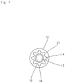
- FIG. 7 is a bottom view of the caulking bolt according to the embodiment of the present invention.
- FIG. 8 is a front view of a rolling die used in the manufacture of the caulking bolt of the present invention.
- FIG. 9 is a sectional view showing a state where the caulking bolt of the present invention has been driven into a metal plate.
- FIG. 10 is a sectional view showing a state where a thin-plate member to be fastened has been fastened.
- FIG. 11 is a graph showing the falling-out load of a caulking bolt of an Example.
- FIG. 12 is a graph showing the idling torque of the caulking bolt of the Example.
- FIG. 6 is a front view of a caulking bolt of an embodiment
- FIG. 7 is a bottom view thereof.
- the caulking bolt of the present invention also includes a head part 11 and a shaft part 12 .
- a non-circular, flat, rotation preventive protrusion 14 is formed on a seat surface 13 of the head part as shown in FIG. 7 .
- the rotation preventive protrusion 14 of this embodiment has a toothed gear shape having concave parts 15 and convex parts 16 formed alternately. While FIG. 7 shows an example where eight concave parts 15 and eight convex parts 16 are formed, the number of each of these parts may also be 3 or 10. However, when the numbers of these parts are increased excessively, the shape of the rotation preventive protrusion 14 gradually approximates a circle, leading to reduction in rotation preventing effect. Therefore, the numbers of concaves and convexes are each preferably defined within a range of about 3 to about 12.
- the radial depth of the concaves and convexes can be determined in consideration of the kind of the metal plate to be caulked.
- the diameter of the concave parts 15 is 60% of the diameter of the head part 11
- the diameter of the convex parts 16 is 60% to 80% of the diameter of the head part 11 .
- the thickness of the rotation preventive protrusion 14 is defined as preferably 1 pitch or less, more preferably about 0.5 pitches of the normal complete thread part 17 formed in the shaft part 12 .
- the pitch of the normal complete thread is 1 mm in the case of M6 bolt, and thus the thickness of the rotation preventive protrusion 14 is defined as 1 mm or less, preferably about 0.5 mm.
- the thickness of the rotation preventive protrusion 14 must be at least about 0.2 mm.
- the characteristic of the caulking bolt of the present invention resides in that the upper end of the normal complete thread part 17 formed in the shaft part 12 is brought close to the seat surface 13 of the head part with a distance of 3 pitches or less, and the incomplete thread part 18 formed at the portion of 3 pitches or less is used as a stopper part into which metal flows when the bolt is driven into the metal plate.
- This method involves forming, in the terminal part of a rolling die 19 , a terminal screw thread part 21 having a lead angle ⁇ which is larger than a lead angle ⁇ of a common screw thread part 20 as shown in FIG. 8 , and, in a final stage of screw rolling by the common screw thread part 20 , moving a blank by a distance corresponding to a lead angle difference ( ⁇ ) to the die side in the terminal screw thread part 21 , thereby making it possible to form the normal complete thread part 17 up to the vicinity of the seat surface 13 of the head part.
- the incomplete thread part 18 is formed at the upper end of the normal complete thread part 17 by this method.
- Such an incomplete thread part 18 has hitherto been considered to be an unnecessary portion which does not function as a screw, but the present invention involves flowing the metal into this portion so that the portion functions as a stopper part, focusing on the fact that this incomplete thread part 18 has concaves and convexes formed in an axial direction.
- FIG. 9 shows a state where the caulking bolt of the embodiment has been driven into a metal plate 22 , and the metal of the metal plate 22 has flowed into the incomplete thread part 18 .
- the metal is made to flow into the incomplete thread part 18 in this manner, the upper surface of the screw thread of the incomplete thread part 18 is constrained by the metal having flowed therein even when axial (upward) pullout load acts on the caulking bolt, so that the fitted bolt cannot be pulled out.
- the caulking bolt of the present invention is configured so that the upper end of the normal complete thread part 17 is brought close to the seat surface 13 of the head part with a distance of 3 pitches or less.
- the metal plate 22 and the member 23 to be fastened are thin plates, fastening by a general nut 24 is possible as shown in FIG. 10 .
- the plate thickness of the metal plate 22 is 1.5 mm (1.5 pitches)
- the distance from the seat surface 13 of the head part to the rear surface of the metal plate 22 is 1.5 mm or less
- the member 23 to be fastened having a plate thickness of 1.5 mm can be fastened by the nut 24 .
- the rear surface 25 of the metal plate 22 into which the caulking bolt has been driven is made flat up to the vicinity of the normal complete thread part 17 in the shaft part 12 . Therefore, the hole diameter of the bolt insertion hole formed in the member 23 to be fastened can be decreased, and the pressure receiving surface at the time of fastening the member 23 to be fastened by means of the nut 24 can be increased.
- a caulking bolt of M6 size as shown in FIGS. 6 and 7 was manufactured by a rolling method.
- the upper end of a normal complete thread part was brought close to a seat surface of a head part with a distance of 1 pitch, and the length of an incomplete thread part was defined as 1 pitch.
- the thickness of the head part was defined as 1.5 mm
- the outer diameter of the head part was defined as 13 mm. Since this bolt is of M6 size, the screw thread diameter of the normal complete thread part formed in a shaft part is 6 mm.
- This caulking bolt was inserted into aluminum plates with various plate thicknesses in which a pilot hole having a diameter of 6.2 mm was formed, and impact load was applied to the head part of the bolt by a punch for caulking. Then, load was applied, in a direction toward the head part, to the shaft tip end part of the bolt to measure the load when the caulking bolt fell out from the aluminum plates as falling-out load.
- the graph of FIG. 11 shows the relationship between the plate thickness of the aluminum plate and the falling-out load. Also when the plate thickness of the aluminum plate is 1 mm, the falling-out load is 0.5 kN (about 50 kgf), which is a value sufficient to prevent the bolt from falling out during conveyance to the nut fastening step after caulking.
- the graph of FIG. 12 shows the relationship between the plate thickness of the aluminum plate and the idling torque.
- the idling torque was measured by a method including applying a rotation torque to the caulking bolt by means of a torque wrench and then measuring the torque when the bolt started to idle. Also when the plate thickness of the aluminum plate is 1 mm, the idling torque is 8 Nm, which sufficiently satisfies the demands of automobile makers.
Landscapes
- Engineering & Computer Science (AREA)
- General Engineering & Computer Science (AREA)
- Mechanical Engineering (AREA)
- Connection Of Plates (AREA)
Applications Claiming Priority (3)
| Application Number | Priority Date | Filing Date | Title |
|---|---|---|---|
| JP2016040181A JP6214696B2 (ja) | 2016-03-02 | 2016-03-02 | かしめボルト |
| JP2016-040181 | 2016-03-02 | ||
| PCT/JP2017/005846 WO2017150210A1 (en) | 2016-03-02 | 2017-02-17 | Caulking bolt |
Related Parent Applications (1)
| Application Number | Title | Priority Date | Filing Date |
|---|---|---|---|
| PCT/JP2017/005846 Continuation WO2017150210A1 (en) | 2016-03-02 | 2017-02-17 | Caulking bolt |
Publications (2)
| Publication Number | Publication Date |
|---|---|
| US20180266475A1 US20180266475A1 (en) | 2018-09-20 |
| US10655666B2 true US10655666B2 (en) | 2020-05-19 |
Family
ID=58231677
Family Applications (1)
| Application Number | Title | Priority Date | Filing Date |
|---|---|---|---|
| US15/984,723 Active US10655666B2 (en) | 2016-03-02 | 2018-05-21 | Caulking bolt |
Country Status (5)
| Country | Link |
|---|---|
| US (1) | US10655666B2 (ja) |
| EP (1) | EP3359830B1 (ja) |
| JP (1) | JP6214696B2 (ja) |
| CN (1) | CN108700104B (ja) |
| WO (1) | WO2017150210A1 (ja) |
Cited By (2)
| Publication number | Priority date | Publication date | Assignee | Title |
|---|---|---|---|---|
| US20210115961A1 (en) * | 2018-07-27 | 2021-04-22 | Aoyama Seisakusho Co., Ltd. | Nut and fixing structure of nut |
| US11242882B2 (en) * | 2017-05-30 | 2022-02-08 | Aoyama Seisakusho Co., Ltd. | Staking bolt |
Families Citing this family (8)
| Publication number | Priority date | Publication date | Assignee | Title |
|---|---|---|---|---|
| JP2019138368A (ja) | 2018-02-09 | 2019-08-22 | 株式会社青山製作所 | かしめボルト |
| CN110685987B (zh) * | 2018-07-06 | 2024-03-15 | 宾工程工厂公司 | 一种压入式紧固件及包括其的组件 |
| US11735837B2 (en) | 2019-10-17 | 2023-08-22 | Production Spring, LLC | Electrical ground strap assemblies providing increased point of contact between a terminal and a bolt |
| US10998648B1 (en) * | 2019-10-17 | 2021-05-04 | Production Spring, LLC | Electrical ground strap assembly providing increased point of contact between a terminal and a bolt |
| CN115667736A (zh) * | 2020-06-19 | 2023-01-31 | 株式会社青山制作所 | 螺栓的锁紧固定结构、自锁螺栓的锁紧固定方法以及锁紧模具 |
| JP7460078B2 (ja) | 2020-07-13 | 2024-04-02 | 株式会社青山製作所 | ボルトのかしめ構造及びかしめ方法 |
| CN113084017A (zh) * | 2021-04-02 | 2021-07-09 | 无锡华光轿车零件有限公司 | 一种改善螺钉铆接性能的安装工艺 |
| JP7473574B2 (ja) | 2022-03-18 | 2024-04-23 | 株式会社豊田中央研究所 | 締結用部材およびその製造方法 |
Citations (16)
| Publication number | Priority date | Publication date | Assignee | Title |
|---|---|---|---|---|
| US3127919A (en) * | 1959-05-06 | 1964-04-07 | Penn Eng & Mfg Corp | Screw with cavity head |
| US3770037A (en) * | 1971-12-15 | 1973-11-06 | Penn Eng Mfg Corp | Self-clinching stud with a modified head |
| US3782436A (en) * | 1972-07-21 | 1974-01-01 | J Steiner | Clinch stud |
| JPS61293620A (ja) | 1985-06-21 | 1986-12-24 | Obatake Tekkosho:Kk | ボルトの製造方法 |
| US4842463A (en) * | 1984-12-10 | 1989-06-27 | Sps Technologies, Inc. | Vibration resistant fasteners |
| US5356253A (en) * | 1992-04-29 | 1994-10-18 | Whitesell Neil L | Sheet metal screw |
| US5513933A (en) * | 1994-04-04 | 1996-05-07 | Textron Inc. | Staked fastener with undercut |
| US6125524A (en) * | 1994-03-25 | 2000-10-03 | Multifastener Corporation | Rivetable element, assembly, method of assembly and riveting die |
| US6206737B1 (en) * | 1999-02-19 | 2001-03-27 | Hubbell Incorporated | Enhanced terminal screw with impeller wire gripping elements |
| US7462043B2 (en) * | 2006-12-15 | 2008-12-09 | Ge Fanuc Embedded Systems, Inc. | Electrical connector element |
| US7815406B2 (en) * | 2004-12-23 | 2010-10-19 | Profil Verbindungstechnik Gmbh & Co., Kg | Element attachable by riveting to a sheet metal part and also a component assembly and a method for the production of the component assembly |
| JP2011241905A (ja) | 2010-05-18 | 2011-12-01 | Fukui Byora Co Ltd | スタッドボルト及びスタッドボルトの製造方法 |
| EP2402620A1 (en) | 2010-06-30 | 2012-01-04 | Pias Sales Co., Ltd. | Clinch bolt |
| US20130302107A1 (en) | 2011-11-07 | 2013-11-14 | Rifast Systems Llc | Clinch fastener |
| US8939689B2 (en) * | 2012-03-27 | 2015-01-27 | Profil Verbindungstechnik Gmbh & Co. Kg | Functional element in the form of a press-in element |
| US9297405B2 (en) * | 2012-01-20 | 2016-03-29 | Profil Verbindungstechnik Gmbh & Co., Kg | Bolt element and a method for the attachment of a bolt element to a component of a composite material |
Family Cites Families (5)
| Publication number | Priority date | Publication date | Assignee | Title |
|---|---|---|---|---|
| DE19535537A1 (de) * | 1995-09-25 | 1997-03-27 | Profil Verbindungstechnik Gmbh | Bolzenelement, Verfahren zum Einsetzen desselben, Zusammenbauteil und Nietmatrize |
| KR20070049672A (ko) * | 2004-08-23 | 2007-05-11 | 씨케이디 가부시키 가이샤 | 볼트 탈락 방지 구조 및 유지 링 |
| JP2013177934A (ja) * | 2012-02-28 | 2013-09-09 | Sakata Seisakusho:Kk | ボルトの固定方法、被固定体およびボルト固定用金型 |
| JP2014040895A (ja) * | 2012-08-23 | 2014-03-06 | Shinnippon Fastener Kogyo Kk | 圧入ボルト |
| CN204371879U (zh) * | 2014-12-12 | 2015-06-03 | Nec显示器解决方案株式会社 | 固定结构及显示装置 |
-
2016
- 2016-03-02 JP JP2016040181A patent/JP6214696B2/ja active Active
-
2017
- 2017-02-17 EP EP17709203.8A patent/EP3359830B1/en active Active
- 2017-02-17 CN CN201780008322.2A patent/CN108700104B/zh active Active
- 2017-02-17 WO PCT/JP2017/005846 patent/WO2017150210A1/en active Application Filing
-
2018
- 2018-05-21 US US15/984,723 patent/US10655666B2/en active Active
Patent Citations (19)
| Publication number | Priority date | Publication date | Assignee | Title |
|---|---|---|---|---|
| US3127919A (en) * | 1959-05-06 | 1964-04-07 | Penn Eng & Mfg Corp | Screw with cavity head |
| US3770037A (en) * | 1971-12-15 | 1973-11-06 | Penn Eng Mfg Corp | Self-clinching stud with a modified head |
| US3782436A (en) * | 1972-07-21 | 1974-01-01 | J Steiner | Clinch stud |
| US4842463A (en) * | 1984-12-10 | 1989-06-27 | Sps Technologies, Inc. | Vibration resistant fasteners |
| JPS61293620A (ja) | 1985-06-21 | 1986-12-24 | Obatake Tekkosho:Kk | ボルトの製造方法 |
| US5356253A (en) * | 1992-04-29 | 1994-10-18 | Whitesell Neil L | Sheet metal screw |
| US6125524A (en) * | 1994-03-25 | 2000-10-03 | Multifastener Corporation | Rivetable element, assembly, method of assembly and riveting die |
| US5513933A (en) * | 1994-04-04 | 1996-05-07 | Textron Inc. | Staked fastener with undercut |
| US6206737B1 (en) * | 1999-02-19 | 2001-03-27 | Hubbell Incorporated | Enhanced terminal screw with impeller wire gripping elements |
| US7815406B2 (en) * | 2004-12-23 | 2010-10-19 | Profil Verbindungstechnik Gmbh & Co., Kg | Element attachable by riveting to a sheet metal part and also a component assembly and a method for the production of the component assembly |
| US7462043B2 (en) * | 2006-12-15 | 2008-12-09 | Ge Fanuc Embedded Systems, Inc. | Electrical connector element |
| JP2011241905A (ja) | 2010-05-18 | 2011-12-01 | Fukui Byora Co Ltd | スタッドボルト及びスタッドボルトの製造方法 |
| EP2402620A1 (en) | 2010-06-30 | 2012-01-04 | Pias Sales Co., Ltd. | Clinch bolt |
| US20120003059A1 (en) * | 2010-06-30 | 2012-01-05 | Pias Sales Co., Ltd. | Clinch bolt |
| JP2012013121A (ja) | 2010-06-30 | 2012-01-19 | Pias Hanbai Kk | クリンチボルト |
| US20130302107A1 (en) | 2011-11-07 | 2013-11-14 | Rifast Systems Llc | Clinch fastener |
| US8979455B2 (en) * | 2011-11-07 | 2015-03-17 | Rifast Systems Llc | Clinch fastener |
| US9297405B2 (en) * | 2012-01-20 | 2016-03-29 | Profil Verbindungstechnik Gmbh & Co., Kg | Bolt element and a method for the attachment of a bolt element to a component of a composite material |
| US8939689B2 (en) * | 2012-03-27 | 2015-01-27 | Profil Verbindungstechnik Gmbh & Co. Kg | Functional element in the form of a press-in element |
Non-Patent Citations (2)
| Title |
|---|
| Chinese Office Action (Application No. 201780008322.2) dated Mar. 26, 2020. |
| International Search Report and Written Opinion (Application No. PCT/JP2017/005846) dated Apr. 7, 2017. |
Cited By (3)
| Publication number | Priority date | Publication date | Assignee | Title |
|---|---|---|---|---|
| US11242882B2 (en) * | 2017-05-30 | 2022-02-08 | Aoyama Seisakusho Co., Ltd. | Staking bolt |
| US20210115961A1 (en) * | 2018-07-27 | 2021-04-22 | Aoyama Seisakusho Co., Ltd. | Nut and fixing structure of nut |
| US11879492B2 (en) * | 2018-07-27 | 2024-01-23 | Aoyama Seisakusho Co., Ltd. | Nut and fixing structure of nut |
Also Published As
| Publication number | Publication date |
|---|---|
| CN108700104A (zh) | 2018-10-23 |
| EP3359830B1 (en) | 2020-11-25 |
| JP6214696B2 (ja) | 2017-10-18 |
| CN108700104B (zh) | 2020-10-02 |
| JP2017155860A (ja) | 2017-09-07 |
| EP3359830A1 (en) | 2018-08-15 |
| WO2017150210A1 (en) | 2017-09-08 |
| US20180266475A1 (en) | 2018-09-20 |
Similar Documents
| Publication | Publication Date | Title |
|---|---|---|
| US10655666B2 (en) | Caulking bolt | |
| JP4294644B2 (ja) | クリンチ形ブラインドナット | |
| JP3781057B2 (ja) | リベッティング可能な要素、組立体、組立方法及びリベッティングダイ | |
| US6817816B2 (en) | Tapping assist fastening element and method | |
| EP2787221B1 (en) | Pierce nut for high-strength steel sheet | |
| US8839486B2 (en) | Press-in element, pre-installation component, component assembly and method | |
| US20100221087A1 (en) | Preload locking Wire Insert | |
| JP2005504243A (ja) | 固定要素 | |
| US10641307B2 (en) | Radiused lead-in for interference fit fasteners | |
| CN108884854B (zh) | 自冲式压入元件、压入连接部和用于制造这种压入连接部的方法 | |
| CN107559286A (zh) | 盲铆钉螺母、具有盲铆钉螺母的固定装置以及固定方法 | |
| US7878748B2 (en) | Threaded fasteners with ribbed shanks | |
| US3828382A (en) | Method of manufacturing a fastener such as a bolt, rivet, or the like | |
| JP4579943B2 (ja) | 平座金圧着ボルトとその製造法 | |
| GB2446815A (en) | Blind stud insert | |
| EP1241364A2 (en) | Bolt and method of clamping members using the same | |
| US6893198B2 (en) | Self-attaching female fastener element and method of attachment | |
| US20080067811A1 (en) | Fastener assembly and manufacturing method therefor | |
| JP2013113396A (ja) | 圧入ナット | |
| WO2014030386A1 (ja) | 圧入ボルト | |
| US20230138175A1 (en) | Blind fastener | |
| WO2021054205A1 (ja) | カシメナット | |
| CN220354252U (zh) | 压铆螺母以及连接系统 | |
| JP6732389B2 (ja) | 板材へのナットとカラーの取付方法及び取付構造 | |
| CN115681269A (zh) | 一种局部自扣紧紧固件及安装方法 |
Legal Events
| Date | Code | Title | Description |
|---|---|---|---|
| AS | Assignment |
Owner name: AOYAMA SEISAKUSHO CO., LTD., JAPAN Free format text: ASSIGNMENT OF ASSIGNORS INTEREST;ASSIGNORS:HOSHINO, NAOKI;OHTA, TOSHIYA;YOSHIDA, MITSUKI;AND OTHERS;SIGNING DATES FROM 20180416 TO 20180511;REEL/FRAME:045860/0001 |
|
| FEPP | Fee payment procedure |
Free format text: ENTITY STATUS SET TO UNDISCOUNTED (ORIGINAL EVENT CODE: BIG.); ENTITY STATUS OF PATENT OWNER: LARGE ENTITY |
|
| STPP | Information on status: patent application and granting procedure in general |
Free format text: DOCKETED NEW CASE - READY FOR EXAMINATION |
|
| STPP | Information on status: patent application and granting procedure in general |
Free format text: NON FINAL ACTION MAILED |
|
| STPP | Information on status: patent application and granting procedure in general |
Free format text: FINAL REJECTION MAILED |
|
| STPP | Information on status: patent application and granting procedure in general |
Free format text: RESPONSE AFTER FINAL ACTION FORWARDED TO EXAMINER |
|
| STPP | Information on status: patent application and granting procedure in general |
Free format text: NOTICE OF ALLOWANCE MAILED -- APPLICATION RECEIVED IN OFFICE OF PUBLICATIONS |
|
| STPP | Information on status: patent application and granting procedure in general |
Free format text: PUBLICATIONS -- ISSUE FEE PAYMENT VERIFIED |
|
| STCF | Information on status: patent grant |
Free format text: PATENTED CASE |
|
| MAFP | Maintenance fee payment |
Free format text: PAYMENT OF MAINTENANCE FEE, 4TH YEAR, LARGE ENTITY (ORIGINAL EVENT CODE: M1551); ENTITY STATUS OF PATENT OWNER: LARGE ENTITY Year of fee payment: 4 |