US10645244B2 - Image reading apparatus with load applying device - Google Patents
Image reading apparatus with load applying device Download PDFInfo
- Publication number
- US10645244B2 US10645244B2 US16/030,709 US201816030709A US10645244B2 US 10645244 B2 US10645244 B2 US 10645244B2 US 201816030709 A US201816030709 A US 201816030709A US 10645244 B2 US10645244 B2 US 10645244B2
- Authority
- US
- United States
- Prior art keywords
- transport
- document
- rotating shaft
- medium
- transport roller
- Prior art date
- Legal status (The legal status is an assumption and is not a legal conclusion. Google has not performed a legal analysis and makes no representation as to the accuracy of the status listed.)
- Active
Links
- 230000032258 transport Effects 0.000 claims abstract description 275
- 238000011144 upstream manufacturing Methods 0.000 claims abstract description 12
- 238000003825 pressing Methods 0.000 claims abstract description 6
- 230000005540 biological transmission Effects 0.000 claims description 51
- 230000006835 compression Effects 0.000 claims description 34
- 238000007906 compression Methods 0.000 claims description 34
- 239000000314 lubricant Substances 0.000 claims description 19
- 239000000463 material Substances 0.000 claims description 12
- 229920005989 resin Polymers 0.000 claims description 7
- 239000011347 resin Substances 0.000 claims description 7
- 238000000926 separation method Methods 0.000 description 27
- 238000001514 detection method Methods 0.000 description 16
- 239000007788 liquid Substances 0.000 description 9
- 239000002131 composite material Substances 0.000 description 8
- 230000004308 accommodation Effects 0.000 description 6
- 238000000465 moulding Methods 0.000 description 5
- 238000000034 method Methods 0.000 description 4
- 239000004519 grease Substances 0.000 description 3
- 230000035939 shock Effects 0.000 description 3
- 230000008901 benefit Effects 0.000 description 2
- 230000008859 change Effects 0.000 description 2
- 230000006866 deterioration Effects 0.000 description 2
- 229920001971 elastomer Polymers 0.000 description 2
- 239000000806 elastomer Substances 0.000 description 2
- 238000009434 installation Methods 0.000 description 2
- 238000004519 manufacturing process Methods 0.000 description 2
- 230000004048 modification Effects 0.000 description 2
- 238000012986 modification Methods 0.000 description 2
- 229920006324 polyoxymethylene Polymers 0.000 description 2
- 230000004044 response Effects 0.000 description 2
- 238000000018 DNA microarray Methods 0.000 description 1
- 229930182556 Polyacetal Natural products 0.000 description 1
- 239000004743 Polypropylene Substances 0.000 description 1
- 239000004793 Polystyrene Substances 0.000 description 1
- 229920000122 acrylonitrile butadiene styrene Polymers 0.000 description 1
- 238000013459 approach Methods 0.000 description 1
- 238000004891 communication Methods 0.000 description 1
- 239000007772 electrode material Substances 0.000 description 1
- 238000005401 electroluminescence Methods 0.000 description 1
- 239000002783 friction material Substances 0.000 description 1
- 239000011521 glass Substances 0.000 description 1
- 239000004973 liquid crystal related substance Substances 0.000 description 1
- 230000007246 mechanism Effects 0.000 description 1
- 230000003287 optical effect Effects 0.000 description 1
- 239000011368 organic material Substances 0.000 description 1
- -1 polypropylene Polymers 0.000 description 1
- 229920001155 polypropylene Polymers 0.000 description 1
- 229920005990 polystyrene resin Polymers 0.000 description 1
- 230000008569 process Effects 0.000 description 1
- 238000012360 testing method Methods 0.000 description 1
Images


Classifications
-
- H—ELECTRICITY
- H04—ELECTRIC COMMUNICATION TECHNIQUE
- H04N—PICTORIAL COMMUNICATION, e.g. TELEVISION
- H04N1/00—Scanning, transmission or reproduction of documents or the like, e.g. facsimile transmission; Details thereof
- H04N1/00567—Handling of original or reproduction media, e.g. cutting, separating, stacking
- H04N1/00628—Separating, e.g. preventing feeding of two sheets at a time
-
- B—PERFORMING OPERATIONS; TRANSPORTING
- B65—CONVEYING; PACKING; STORING; HANDLING THIN OR FILAMENTARY MATERIAL
- B65H—HANDLING THIN OR FILAMENTARY MATERIAL, e.g. SHEETS, WEBS, CABLES
- B65H5/00—Feeding articles separated from piles; Feeding articles to machines
- B65H5/06—Feeding articles separated from piles; Feeding articles to machines by rollers or balls, e.g. between rollers
-
- H—ELECTRICITY
- H04—ELECTRIC COMMUNICATION TECHNIQUE
- H04N—PICTORIAL COMMUNICATION, e.g. TELEVISION
- H04N1/00—Scanning, transmission or reproduction of documents or the like, e.g. facsimile transmission; Details thereof
- H04N1/00567—Handling of original or reproduction media, e.g. cutting, separating, stacking
- H04N1/0057—Conveying sheets before or after scanning
- H04N1/00599—Using specific components
- H04N1/00602—Feed rollers
-
- H—ELECTRICITY
- H04—ELECTRIC COMMUNICATION TECHNIQUE
- H04N—PICTORIAL COMMUNICATION, e.g. TELEVISION
- H04N1/00—Scanning, transmission or reproduction of documents or the like, e.g. facsimile transmission; Details thereof
- H04N1/00681—Detecting the presence, position or size of a sheet or correcting its position before scanning
- H04N1/00785—Correcting the position of a sheet before scanning
- H04N1/00793—Correcting the position of a sheet before scanning using paper feeding mechanism, e.g. operate drive rollers at different speeds
-
- H—ELECTRICITY
- H04—ELECTRIC COMMUNICATION TECHNIQUE
- H04N—PICTORIAL COMMUNICATION, e.g. TELEVISION
- H04N1/00—Scanning, transmission or reproduction of documents or the like, e.g. facsimile transmission; Details thereof
- H04N1/00795—Reading arrangements
- H04N1/00798—Circuits or arrangements for the control thereof, e.g. using a programmed control device or according to a measured quantity
- H04N1/00801—Circuits or arrangements for the control thereof, e.g. using a programmed control device or according to a measured quantity according to characteristics of the original
- H04N1/00806—According to type of the original, e.g. colour paper or transparency, or reading a plurality of different types of original
-
- B—PERFORMING OPERATIONS; TRANSPORTING
- B65—CONVEYING; PACKING; STORING; HANDLING THIN OR FILAMENTARY MATERIAL
- B65H—HANDLING THIN OR FILAMENTARY MATERIAL, e.g. SHEETS, WEBS, CABLES
- B65H2402/00—Constructional details of the handling apparatus
- B65H2402/70—Lubrication
-
- B—PERFORMING OPERATIONS; TRANSPORTING
- B65—CONVEYING; PACKING; STORING; HANDLING THIN OR FILAMENTARY MATERIAL
- B65H—HANDLING THIN OR FILAMENTARY MATERIAL, e.g. SHEETS, WEBS, CABLES
- B65H2403/00—Power transmission; Driving means
-
- B—PERFORMING OPERATIONS; TRANSPORTING
- B65—CONVEYING; PACKING; STORING; HANDLING THIN OR FILAMENTARY MATERIAL
- B65H—HANDLING THIN OR FILAMENTARY MATERIAL, e.g. SHEETS, WEBS, CABLES
- B65H2403/00—Power transmission; Driving means
- B65H2403/40—Toothed gearings
-
- B—PERFORMING OPERATIONS; TRANSPORTING
- B65—CONVEYING; PACKING; STORING; HANDLING THIN OR FILAMENTARY MATERIAL
- B65H—HANDLING THIN OR FILAMENTARY MATERIAL, e.g. SHEETS, WEBS, CABLES
- B65H2403/00—Power transmission; Driving means
- B65H2403/70—Clutches; Couplings
- B65H2403/72—Clutches, brakes, e.g. one-way clutch +F204
- B65H2403/725—Brakes
-
- B—PERFORMING OPERATIONS; TRANSPORTING
- B65—CONVEYING; PACKING; STORING; HANDLING THIN OR FILAMENTARY MATERIAL
- B65H—HANDLING THIN OR FILAMENTARY MATERIAL, e.g. SHEETS, WEBS, CABLES
- B65H2404/00—Parts for transporting or guiding the handled material
- B65H2404/10—Rollers
- B65H2404/16—Details of driving
- B65H2404/165—Details of driving braking roller
Definitions
- the present invention relates to an image reading apparatus that reads a surface of a medium.
- An example of an image reading apparatus is a scanner that includes an automatic document feeder (such as “ADF”, i.e., “auto document feeder”) and is configured to feed and read a plurality of documents automatically.
- the auto document feeder is formed, for example, such that a document support section that supports documents feeds a document and the document is inverted along a U-shaped transport path, transported to a document-reading position, and subsequently read and discharged toward a discharge tray.
- An example of a scanner equipped with such a type of auto document feeder is described in JP-A-2008-156088.
- rollers are disposed on the document transport path. These rollers include a feed roller that feeds a document from the document support section that supports documents before feeding and a transport roller that is disposed in a region upstream of, and close to, a reading section for reading the document and transports the document to the reading section.
- a separation device is disposed at a position opposing the feed roller, and the feed roller and the separation device nip an individual document so as to prevent multi-feeding.
- the trailing end of a document comes off from a nip position between the feed roller and the separation device, the trailing end of the document may be tossed out from the nip position.
- the document transport speed of the transport roller disposed downstream increases temporarily, which may generate a disturbed portion in a read image (so-called “singularity”).
- One way to avoid such a problem is, for example, to reduce the load that is applied when the document is nipped by the feed roller and the separation device. However, this approach may degrade document separation performance.
- An advantage of some aspects of the invention is that an image reading apparatus that can efficiently suppress disturbance in the document transport speed when the trailing end of a document passes a nip position located upstream of a transport roller is provided.
- An image reading apparatus includes a medium support section that supports a medium before feeding, a reading section that reads the medium that feeds from the medium support section, a transport roller that is disposed upstream of the reading section and transports the medium to the reading section, and a load applying device that applies a load against rotation of the transport roller.
- the image reading apparatus includes the transport roller that is disposed upstream of the reading section and transports the medium to the reading section and the load applying device that applies a load against rotation of the transport roller.
- the load applying device applies a braking force against rotation of the transport roller, which can efficiently suppress the disturbance in the document transport speed of the transport roller.
- the transport roller be disposed on a rotating shaft that extends in a medium width direction that intersects the medium transport direction, and that the load applying device impart the load by pressing a transport roller driving gear disposed at one end of the rotating shaft in a direction from the one end of the rotating shaft to the other end thereof.
- the load applying device imparts the load by pressing a transport roller driving gear disposed at one end of the rotating shaft in a direction from the one end of the rotating shaft to the other end thereof.
- the image reading apparatus further include a position regulator that regulates position of the rotating shaft in the rotation axis direction of the rotating shaft. It is also preferable that in the image reading apparatus, the position regulator be disposed at a position closer to the one end of the rotating shaft than to the other end thereof in the rotation axis direction.
- the position at which the load applying device imparts a load onto the rotating shaft is in a region closer to one end of the rotating shaft, and the position of the position regulator that regulates the position of the rotating shaft in the rotation axis direction is also in a region closer to the same end of the rotating shaft. This can reduce the length of section of the rotating shaft in which torsion occurs, and thereby can suppress disturbance in transport speed caused by the torsion of the rotating shaft.
- At least a portion of the transport roller driving gear be present within a medium transport region in the medium width direction. According to this configuration, at least a portion of the transport roller driving gear is present within the medium transport region. As a result, the distance between the transport roller and the position at which torque is transmitted to the rotating shaft of the transport roller becomes short, thereby reducing torsion of the rotating shaft and consequently suppressing deterioration in the medium transport accuracy of the transport roller.
- the image reading apparatus further include a gear set that transmits power from a drive source to the transport roller driving gear, and a transport path forming unit that supports the gear set on one side of the transport path forming unit in the medium width direction.
- the transport path forming unit have a recess formed on the one side, and at least a portion of the gear set is present in the recess. According to this configuration, the transport path forming unit has the recess formed at the one end, and at least a portion of the gear set is present in the recess, thereby reducing an increase in the size of the apparatus caused by installation of the gear set.
- the transport path forming unit include a shaft support portion that supports the rotating shaft and a lubricant retainer that retains a lubricant to be supplied to the shaft support portion.
- the transport path forming unit includes the shaft support portion that supports the rotating shaft and the lubricant retainer that retains a lubricant to be supplied to the shaft support portion.
- the lubricant supplied by the shaft support portion can reduce wear and tear of the shaft support portion and the rotating shaft.
- the load applying device include a compression spring, and the compression spring exert a spring force on the spring retainer disposed in the recess and also on the transport roller driving gear.
- the load applying device include the compression spring. The load applying device can be thereby formed in a simple structure and at a low cost.
- the compression spring be fixed to the spring retainer, and a sliding member be disposed between the compression spring and the transport roller driving gear.
- the compression spring is fixed to the spring retainer, and the sliding member is disposed between the compression spring and the transport roller driving gear.
- a sliding portion where sliding occurs when the rotating shaft rotates is limited to the portion between the compression spring and the sliding member.
- the sliding load is maintained stable during rotation of the rotating shaft, and wear of the transport roller driving gear can be reduced.
- the transport roller and the rotating shaft be formed by using two types of resin materials.
- the transport roller and the rotating shaft are formed of resin materials by using a double-molding method.
- the transport roller and the rotating shaft can be formed at a low cost.
- the image reading apparatus further include an apparatus body that includes the reading section and a placement table on which a document is placed, and a document transport apparatus that is disposed so as to be openable relative to the apparatus body and that transports the document to a reading region on the placement table.
- the document transport apparatus be formed of the medium support section, the medium feed path, and the transport roller, that the apparatus body include a drive source that provides power to be transmitted to the transport roller, and the drive source be used for moving the reading section relative to the placement table, and that when the document transport apparatus is closed relative to the apparatus body, a transmission path for transmitting driving power from the drive source to the transport roller be formed.
- the drive source is used to drive both the document transport apparatus and the reading section, which can reduce the cost of the apparatus.
- FIG. 1 is a perspective view illustrating an external appearance of a printer according to the invention.
- FIG. 2 is a perspective view illustrating a state of an image reading apparatus according to the invention in which a document transport apparatus is open relative to an apparatus body.
- FIG. 3 is a perspective view illustrating a state of the printer in which the document transport apparatus is ready to feed a document.
- FIG. 4 is a cross-sectional side view illustrating the image reading apparatus and a document transport path in the document transport apparatus.
- FIG. 5 is a perspective view illustrating transport rollers and a rotating shaft for the transport rollers in a transport path forming unit in the document transport apparatus.
- FIG. 6 is a perspective view illustrating a load applying device that imparts a load onto the rotating shaft of the transport rollers.
- FIG. 7 is a cross-sectional side view illustrating the load applying device.
- FIG. 8 is an exploded perspective view illustrating the load applying device.
- FIG. 9 is a perspective view illustrating a spring retainer.
- FIG. 10 is a perspective view illustrating a state in which a compression spring is fixed to the spring retainer.
- FIG. 11 is a cross-sectional side view illustrating another example of the load applying device.
- FIG. 12 is a cross-sectional side view illustrating still another example of the load applying device.
- FIG. 13 is a perspective view illustrating shaft support portions for the rotating shaft and lubricant retainers.
- FIG. 14 is a perspective view illustrating a power transmission device in the document transport apparatus.
- FIG. 15 is a perspective view illustrating a first power transmission path and a second power transmission path.
- FIG. 16 is a plan view illustrating a bottom side of the transport path forming unit.
- FIG. 17 is a plan view illustrating a drive motor disposed in the apparatus body and a transmission path of driving power to the power transmission device.
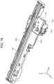
- FIG. 18 is a cross-sectional side view illustrating a state of power transmission from the apparatus body to the document transport apparatus when the document transport apparatus is closed relative to the apparatus body.
- FIG. 19 is a perspective view illustrating a reading section.
- FIG. 20 is an exploded perspective view illustrating the power transmission device in the reading section.
- FIG. 21 is a cross-sectional side view illustrating the power transmission device in the reading section.
- FIG. 22 is a perspective view illustrating a top side of the transport path forming unit.
- FIG. 23 is a cross-sectional side view illustrating a detected state and an undetected state of a document detection sensor in the transport path forming unit.
- FIG. 24 is a cross-sectional side view illustrating a curved inversion section that bends and inverts a document along the document transport path.
- FIG. 25 is a perspective view illustrating an edge portion of the top surface of the apparatus body of the image reading apparatus.
- FIG. 26 is a cross-sectional side view illustrating an edge portion of the top surface of the apparatus body of the image reading apparatus.
- FIG. 1 is a perspective view illustrating an external appearance of a printer according to the invention.
- FIG. 2 is a perspective view illustrating a state of an image reading apparatus according to the invention in which a document transport apparatus is open relative to an apparatus body.
- FIG. 3 is a perspective view illustrating a state of the printer in which the document transport apparatus is ready to feed a document.
- FIG. 4 is a cross-sectional side view illustrating the image reading apparatus and a document transport path in the document transport apparatus.
- FIG. 5 is a perspective view illustrating transport rollers and a rotating shaft for the transport rollers in a transport path forming unit in the document transport apparatus.
- FIG. 6 is a perspective view illustrating a load applying device that imparts a load onto the rotating shaft of the transport rollers.
- FIG. 7 is a cross-sectional side view illustrating the load applying device.
- FIG. 8 is an exploded perspective view illustrating the load applying device.
- FIG. 9 is a perspective view illustrating a spring retainer.
- FIG. 10 is a perspective view illustrating a state in which a compression spring is fixed to the spring retainer.
- FIG. 11 is a cross-sectional side view illustrating another example of the load applying device.
- FIG. 12 is a cross-sectional side view illustrating still another example of the load applying device.
- FIG. 13 is a perspective view illustrating shaft support portions for the rotating shaft and lubricant retainers.
- FIG. 14 is a perspective view illustrating a power transmission device in the document transport apparatus.
- FIG. 15 is a perspective view illustrating a first power transmission path and a second power transmission path.
- FIG. 16 is a plan view illustrating a bottom side of the transport path forming unit.
- FIG. 17 is a plan view illustrating a drive motor disposed in the apparatus body and a transmission path of driving power to the power transmission device.
- FIG. 18 is a cross-sectional side view illustrating a state of power transmission from the apparatus body to the document transport apparatus when the document transport apparatus is closed relative to the apparatus body.
- FIG. 19 is a perspective view illustrating a reading section.
- FIG. 20 is an exploded perspective view illustrating the power transmission device in the reading section.
- FIG. 21 is a cross-sectional side view illustrating the power transmission device in the reading section.
- FIG. 22 is a perspective view illustrating a top side of the transport path forming unit.
- FIG. 23 is a cross-sectional side view illustrating a detected state and an undetected state of a document detection sensor in the transport path forming unit.
- FIG. 24 is a cross-sectional side view illustrating a curved inversion section that bends and inverts a document along the document transport path.
- FIG. 25 is a perspective view illustrating an edge portion of the top surface of the apparatus body of the image reading apparatus.
- FIG. 26 is a cross-sectional side view illustrating an edge portion of the top surface of the apparatus body of the image reading apparatus.
- the X direction represents the width direction of a document, in other words, in the depth direction of the apparatus
- the Y direction represents the transport direction of the document along the transport path in the image reading apparatus, in other words, the width direction of the apparatus
- the Z direction represents the height direction of the apparatus.
- the printer 10 is formed as an ink jet printer, which is an example of a recording apparatus.
- the printer 10 is formed as a multifunction machine constituted by a recording apparatus section 12 and an image reading apparatus 14 .
- the image reading apparatus 14 is formed, for example, as a scanner unit.
- the image reading apparatus 14 is rotatably connected to a backside edge of the recording apparatus section 12 in the apparatus depth direction. Although not illustrated, when the image reading apparatus 14 is rotated toward the backside of the apparatus, an upper portion of the recording apparatus section 12 will be exposed.
- the image reading apparatus 14 includes an apparatus body 16 and a document transport apparatus 18 .
- the document transport apparatus 18 is formed, for example, as an auto document feeder (ADF).
- the document transport apparatus 18 is also rotatably connected to the backside edge of the apparatus body 16 in the apparatus depth direction. Rotating the document transport apparatus 18 toward the backside of the apparatus can expose a document placement table 20 , which is otherwise called a “placement table”, disposed on the top side of the apparatus body 16 . In this state, a document, which is otherwise called a “medium”, can be set on the document placement table 20 .
- the document placement table 20 is formed of a glass plate that is transparent and flat. Note that photographs and text are examples of the “document” according to the embodiment.
- a cover section 22 and a discharge tray 24 are formed on the top side of the document transport apparatus 18 .
- the cover section 22 and the discharge tray 24 are rotatably attached to the document transport apparatus 18 and are formed so as to be switchable between an unfeedable state ( FIG. 1 ) and a feedable state ( FIG. 3 ).
- the cover section 22 and the discharge tray 24 are positioned parallel to the X-axis and the Y-axis and constitute part of a top surface 18 a of the document transport apparatus 18 .
- the top surface 18 a of the document transport apparatus 18 can form a flat surface, which improves the aesthetic appearance of the apparatus.
- a document support section 26 which is otherwise called a “medium support section”, is exposed.
- the document support section 26 is formed so as to enable a plurality of documents to be set thereon and support the documents in collaboration with the cover section 22 assuming the feedable state.
- a document transport path 28 which is otherwise called a “medium feed path”, will be described with reference to FIGS. 4 and 24 .
- the dash-dot-dot line denoted by reference P indicates a transport path of a document transported along the document transport path 28 .
- a feed roller 30 a separation roller 32 , a transport roller pair 34 , a reading device 36 , and a discharge roller pair 38 are disposed downstream of the document support section 26 in this order.
- a portion of the document transport path 28 from the separation roller 32 to the transport roller pair 34 is formed as a curved inversion path 40 .
- the feed roller 30 is formed so as to rotate by receiving power via a first power transmission path 86 ( FIG. 14 ), which will be described later.
- an idler roller 42 is disposed at a position opposing the feed roller 30 .
- the idler roller 42 is formed so as to rotate passively in conjunction with the feed roller 30 .
- the idler roller 42 is provided to reduce friction between the feed roller 30 and an opposing surface when the feed roller 30 finishes feeding a document but is still rotating. This reduces the likelihood of read images being affected by a transport load.
- a separation pad 44 is disposed at a position opposing the separation roller 32 .
- the separation pad 44 is in contact with the separation roller 32 .
- the separation pad 44 is made of, for example, a high-friction material.
- a plurality of documents fed by the feed roller 30 are separated by the separation roller 32 and the separation pad 44 , and consequently, only the document with which the separation roller 32 is in contact is transported toward the transport roller pair 34 disposed downstream in the document transport direction. In the process in which the document is transported from the separation roller 32 to the transport roller pair 34 , in other words, while the document passes the curved inversion path 40 , the document is curved and inverted.
- the document tries to return to its original flat shape.
- the document may stick to a peripheral-side surface of the curved inversion path 40 , which increases the friction between the document and the curved inversion path 40 and may cause paper jamming on the curved inversion path 40 .
- protrusions 46 that are shaped like ribs are disposed on the curved inversion path 40 at positions between the separation roller 32 and pad 44 and the transport roller pair 34 .
- the protruding amount of the protrusions 46 ( FIGS. 22 and 24 ) on the curved inversion path 40 is set such that the curvature of the document on the curved inversion path 40 is made as gentle as possible.
- the protrusions 46 are disposed downstream of, and close to, the separation roller 32 in the document transport direction.
- a plurality of idler rollers are disposed between the transport roller pair 34 and the protrusions 46 of the curved inversion path 40 in the document transport direction.
- three idler rollers 48 A, 48 B, and 48 C are disposed in this order in the document transport direction.
- a document transport speed of the transport roller pair 34 is set faster than that by the separation roller 32 .
- the idler rollers 48 A, 48 B, 48 C come into contact with the document that passes along the inner-side surface of the curved inversion path 40 and cause the document to pass smoothly.
- the idler roller 48 A is disposed at a position overlapping the protrusions 46 on the document transport path, which reduces a transport load applying to the document.
- the transport roller pair 34 includes a transport drive roller 34 a and an idler roller 34 b .
- the transport drive roller 34 a is formed so as to be driven by power received via a second power transmission path ( FIG. 14 ), which will be described later.
- the idler roller 34 b is formed so as to rotate passively in conjunction with the transport drive roller 34 a.
- the reading device 36 is disposed downstream of the transport roller pair 34 .
- the document, which has been transported to the reading device 36 by the transport roller pair 34 is read by a reading section 50 that is positioned at a position that opposes the document with the document placement table 20 interposed therebetween.
- the document, which has been read by the reading section 50 at the document placement table 20 is transported to the discharge roller pair 38 disposed downstream of the reading device 36 on the document transport path 28 , and the discharge roller pair 38 discharges the document onto the discharge tray 24 .
- the discharge roller pair 38 includes a discharge drive roller 38 a and an idler roller 38 b .
- the discharge drive roller 38 a is formed so as to rotate in response to power received via the first power transmission path 86 ( FIG. 14 ), which will be described later.
- the idler roller 38 b is formed so as to rotate passively in conjunction with the discharge drive roller 38 a.
- a transport path forming unit 52 which is illustrated in FIG. 5 , forms the document transport path 28 and part of the curved inversion path 40 in the document transport apparatus 18 .
- the transport path forming unit 52 is made of, for example, ABS resin.
- a plurality of shaft support portions 52 a are disposed at the +Y end of the transport path forming unit 52 in the Y direction and are arranged in a row in the X direction with an appropriate spacing therebetween.
- a rotating shaft 54 is rotatably mounted on the shaft support portions 52 a.
- some of the shaft support portions 52 a have a lubricant retainer 52 b formed therein.
- the lubricant retainer 52 b is formed, for example, as a recess so as to retain a lubricant therein.
- the lubricant retainer 52 b supplies an appropriate amount of the lubricant to the interface between the shaft support portion 52 a and the rotating shaft 54 in response to the rotation of the rotating shaft 54 , thereby improving slidability of the rotating shaft 54 .
- grease may be used as the lubricant.
- a position regulator 52 c is formed at the +Y end of the transport path forming unit 52 in the Y direction.
- the position regulator 52 c In the axial direction of the rotating shaft (in the X direction), the position regulator 52 c is located, along the rotating shaft 54 , at a position closer to one end thereof than to the other end, in other words, closer to the +X end of the rotating shaft 54 in the X direction in FIG. 5 .
- the position regulator 52 c is formed as a recess.
- the transport drive roller 34 a is formed on the rotating shaft 54 at two positions with a spacing therebetween in the X direction.
- two transport drive rollers 34 a are integrally formed with the rotating shaft 54 by using a double-molding method (different-material molding).
- the rotating shaft 54 is formed of a resin material (denatured polypropylene in the embodiment), whereas the transport drive rollers 34 a are formed of an elastomer.
- a position regulator engaging portion 54 a which is shaped like a flange, is also formed on the rotating shaft 54 at a position corresponding to the position regulator 52 c in the X direction.
- the position regulator engaging portion 54 a comes within the position regulator 52 c .
- the position regulator 52 c thereby regulates the position of the rotating shaft 54 in the axial direction of the rotating shaft 54 (in the X direction) with respect to the transport path forming unit 52 .
- a recess 52 e is formed on a +X side 52 d of the transport path forming unit 52 in the X direction.
- the recess 52 e is recessed in the ⁇ X direction from the +X side 52 d .
- One end 54 b of the rotating shaft 54 (the +X end of the rotating shaft 54 in the X direction) is formed so as to protrude within the recess 52 e .
- the other end 54 c of the rotating shaft 54 is positioned within the transport path forming unit 52 in the X direction.
- a transport roller driving gear 56 is fixed to the one end 54 b of the rotating shaft 54 .
- a load applying device 58 ( FIGS. 6 and 7 ) that imparts a load onto the rotating shaft 54 is also attached to the one end 54 b of the rotating shaft 54 .
- a description of the load applying device 58 is as follows. As illustrated in FIG. 8 , the load applying device 58 includes a sliding member 60 , a compression spring 62 , and a spring retainer 64 .
- the transport roller driving gear 56 is formed, for example, of polyacetal resin (POM).
- the sliding member 60 is shaped like a washer and made of Polyslider material.
- the spring retainer 64 has a fixation portion 64 a , a spring accommodation portion 64 b , a groove portion 64 c , and a contact portion 64 d .
- the spring retainer 64 is formed, for example, of polystyrene resin (PS material).
- PS material polystyrene resin
- a through-hole is formed in the fixation portion 64 a and in the spring accommodation portion 64 b .
- the groove portion 64 c is in communication with the spring accommodation portion 64 b .
- the contact portions 64 d are formed as a pair in the groove portion 64 c at positions opposing each other.
- the compression spring 62 shaped like a coil is mounted on the spring accommodation portion 64 b .
- one end of the compression spring 62 is formed so as to protrude from the coil, which serves as a stopper 62 a .
- the stopper 62 a extends from the spring accommodation portion 64 b toward the groove portion 64 c .
- the stopper 62 a comes into contact with one member of the pair of the contact portions 64 d disposed within the groove portion 64 c and prevents the compression spring 62 from rotating on its axis.
- a spring retainer fixation portion 52 f protrudes in the recess 52 e of the transport path forming unit 52 .
- the one end 54 b of the rotating shaft 54 protrudes from the recess 52 e and is passed through the transport roller driving gear 56 , two sliding members 60 , the compression spring 62 , and the through-hole of the spring accommodation portion 64 b of the spring retainer 64 in this order.
- the fixation portion 64 a of the spring retainer 64 engages the spring retainer fixation portion 52 f .
- a fastening member 66 is passed through the through-hole of the fixation portion 64 a of the spring retainer 64 and is tightened so as to fasten the spring retainer 64 to the spring retainer fixation portion 52 f .
- the load applying device 58 is thereby mounted on the transport path forming unit 52 ( FIG. 6 ). Note that the load applying device 58 is attached to the transport path forming unit 52 so as to enable the compression spring 62 to generate an arbitrary load (spring force).
- one end of the compression spring 62 is fixed to the transport path forming unit 52 via the spring retainer 64 .
- the other end of the compression spring 62 presses the transport roller driving gear 56 , which is fixed to the one end 54 b of the rotating shaft 54 , in a direction from the one end 54 b of the rotating shaft 54 (from the +X end of the rotating shaft 54 in the X direction) toward the other end 54 c (toward the ⁇ X end of the rotating shaft 54 ).
- Two sliding members 60 are interposed between the other end of the compression spring 62 and the transport roller driving gear 56 .
- the load applying device 58 thereby imparts a load onto the rotating shaft 54 from the +X end of the rotating shaft 54 toward the ⁇ X end thereof in the axial direction.
- the load imparted by the load applying device 58 generates a braking force (braking load) against the rotation of the rotating shaft 54 and consequently against the rotation of the transport drive rollers 34 a .
- a braking force braking load
- the load applying device 58 can reduce the disturbance in the transport speed of the document and consequently reduce the disturbance in image reading in the reading device 36 .
- the contact portion 64 d restrains the compression spring 62 from rotating relative to the spring retainer 64 . Accordingly, when the rotating shaft 54 rotates, the compression spring 62 does not rotate together with the rotating shaft 54 . Thus, a portion where sliding occurs when the rotating shaft 54 rotates can be limited to the portion between the compression spring 62 and the sliding member 60 . As a result, the sliding load is maintained stable during rotation of the rotating shaft 54 , and wear of the transport roller driving gears 56 can be suppressed.
- the load applying device 58 is formed so as to impart the load from the compression spring 62 to the rotating shaft 54 in the axial direction thereof and thereby apply a braking force to the transport drive rollers 34 a .
- the braking force may be applied to the rotating shaft 54 , and thus to the transport drive rollers 34 a , by applying a load onto the rotating shaft 54 in the radial direction thereof.
- one end 68 a of a torsion spring 68 engages the transport path forming unit 52 , and the other end 68 b is brought into contact with the circumferential surface of the rotating shaft 70 .
- the rotating shaft 70 can be pressed in the radial direction.
- a groove 70 a may be disposed around the circumferential surface of the rotating shaft 70 so as not to displace the other end 68 b in the axial direction of the rotating shaft 70 , wherein the other end 68 b enters the groove 70 a and presses the rotating shaft 70 .
- one end 72 a of a compression spring 72 engages the transport path forming unit 52 , and the other end 72 b is brought into contact with the circumferential surface of the rotating shaft 74 . In this state, the rotating shaft 74 can be pressed in the radial direction thereof.
- a braking force (braking load) can be applied against the rotation of the rotating shaft 70 or 74 .
- the load applying device 58 can reduce the disturbance in the document transport speed of the transport roller pairs 34 .
- a power transmission device 76 will be described with reference to FIGS. 14 and 15 .
- the power transmission device 76 is disposed in a +Y region of the +X side 52 d of the transport path forming unit 52 that forms the document transport path 28 and the curved inversion path 40 .
- the power transmission device 76 is formed so as to transmit the power of a drive motor 78 ( FIGS. 17 and 21 ), which is otherwise called a “drive source” and is disposed in the apparatus body 16 , to the feed roller 30 , the transport drive roller 34 a , and the discharge drive roller 38 a .
- a power transmission path from the drive motor 78 within the apparatus body to the power transmission device 76 will be described later.
- the power transmission device 76 is formed as a gear set that includes a first bevel gear 80 , a second bevel gear 82 , an input gear 84 , a first power transmission path 86 , and a second power transmission path 88 .
- the first bevel gear 80 is disposed in the document transport apparatus 18 with its axis extending in the Z direction.
- the first bevel gear 80 is formed so as to rotate by receiving power transmitted from the drive motor 78 ( FIGS. 17 and 21 ).
- the first bevel gear 80 engages the second bevel gear 82 .
- the second bevel gear 82 is formed, for example, as a composite gear.
- the second bevel gear 82 has a spur gear (not shown), and the spur gear engages the input gear 84 .
- the second bevel gear 82 and the input gear 84 also rotate.
- the input gear 84 is disposed in the power transmission device 76 at a position where the power is distributed to the first power transmission path 86 and to the second power transmission path 88 .
- the input gear 84 which is formed as a composite gear, includes a first input gear 84 A that transmits power to the first power transmission path 86 and a second input gear 84 B that transmits power to the second power transmission path 88 .
- first input gear 84 A is formed so as to engage the spur gear (not shown) of the second bevel gear 82 and receive power from the drive motor 78 ( FIGS. 17 and 21 ).
- the first power transmission path 86 is formed as a gear set including a plurality of gears.
- the first power transmission path 86 includes gears 90 A, 90 B, 90 C, 90 D, and 90 E.
- the gear 90 A engages the first input gear 84 A.
- the gear 90 B engages the gear 90 A, the gear 90 C, and the gear 90 D individually.
- the gear 90 C engages the gear 90 E.
- the gear 90 D rotates in conjunction with the rotation of the gear 90 B that engages the gear 90 D.
- the gear 90 D is fixed to the +X end of a rotating shaft 92 in the X direction.
- the rotation of the rotating shaft 92 transmits power to the feed roller 30 and the separation roller 32 .
- the rotation of the gear 90 C that engages the gear 90 E causes the gear 90 E to rotate.
- the discharge drive roller 38 a is fixed to a rotating shaft 94 that rotates together with the gear 90 E.
- the discharge drive roller 38 a is disposed on a rotating shaft 94 at two positions with a spacing therebetween in the X direction.
- the gear 90 E is fixed to the +X end of the rotating shaft 94 in the X direction. Accordingly, when the gear 90 E rotates, the discharge drive rollers 38 a are caused to rotate via the rotating shaft 94 .
- the second power transmission path 88 includes a gear 96 and the transport roller driving gear 56 .
- the gear 96 engages the second input gear 84 B.
- the transport roller driving gear 56 engages the gear 96 .
- the gear 96 is disposed, together with the transport roller driving gear 56 , within the recess 52 e ( FIG. 8 ) on the +X side 52 d of the transport path forming unit 52 .
- the rotation of the input gear 84 causes the feed roller 30 , the transport drive roller 34 a , and the discharge drive roller 38 a to rotate in a direction of transporting a document from an upstream region to a downstream region along the document transport path 28 .
- the dash-dot-dot line denoted by reference X 1 indicates the +X end of the document transport path 28 (curved inversion path 40 ) in the document width direction (in the X direction).
- at least a portion of the transport roller driving gear 56 is present inside the dash-dot-dot line X 1 in the X direction, in other words, within the curved inversion path 40 .
- the transport roller driving gear 56 can transmit power (torque) to the transport drive rollers 34 a at a position close to the transport drive rollers 34 a in the X direction, thereby suppressing torsion of the rotating shaft 54 .
- the load applying device 58 can apply a load (braking force) to the transport drive rollers 34 a at a position close to the transport drive rollers 34 a , thereby suppressing the torsion of the rotating shaft 54 .
- the reading section 50 is disposed inside the apparatus body 16 .
- the reading section 50 is formed, for example, so as to be movable in the Y direction by using a rack and pinion mechanism.
- the reading section 50 has a carriage 50 a .
- the carriage 50 a includes a sensor 50 b that extends in the X direction, the drive motor 78 ( FIGS. 17 and 21 ), a driving gear 98 ( FIGS. 17 and 20 ), a gear 100 , and a pinion 102 .
- the sensor 50 b is formed, for example, as a contact image sensor module (CISM).
- CISM contact image sensor module
- the driving gear 98 is fixed to the drive shaft of the drive motor 78 .
- the driving gear 98 engages the gear 100 .
- the gear 100 engages the pinion 102 .
- the drive motor 78 is rotationally driven such that the pinion 102 in FIG. 17 rotates clockwise, the pinion 102 engages a rack 104 and moves the reading section 50 in the ⁇ Y direction. This enables the reading section 50 to read a document that is placed on the document placement table 20 while the reading section 50 moves in the Y direction.
- the composite gear 112 has an engaging portion 112 a ( FIG. 18 ) that is shaped like a pipe and formed so as to protrude upward (in the Z direction).
- a connection portion 80 a is disposed at the bottom end of the first bevel gear 80 .
- the connection portion 80 a and the engaging portion 112 a are connected to each other.
- the composite gear 112 and the first bevel gear 80 can rotate together as one body.
- the composite gear 112 is caused to rotate counterclockwise in FIG. 17 by power from the drive motor 78 ( FIGS. 17 and 21 )
- the first bevel gear 80 rotates in the same direction.
- the power of the drive motor 78 is transmitted to the first bevel gear 80 , and consequently to the power transmission device 76 .
- a plurality of gears including those from the gear 100 to the composite gear 112 constitute a third power transmission path 114 ( FIG. 17 ) that transmits power from the drive motor 78 to the power transmission device 76 disposed in the document transport apparatus 18 .
- the carriage 50 a in the reading section 50 has supporting shafts 50 c and 50 d ( FIG. 20 ).
- the gear 100 is inserted to the supporting shaft 50 c so as to be rotatable relative to the supporting shaft 50 c .
- the pinion 102 is inserted to the supporting shaft 50 d so as to be rotatable relative to the supporting shaft 50 d.
- a cover member 116 ( FIG. 20 ) is attached to the carriage 50 a while the gear 100 and the pinion 102 are inserted to the supporting shafts 50 c and 50 d , respectively.
- the cover member 116 defines the top positions of the supporting shafts 50 c and 50 d .
- the cover member 116 serves as a lid while the gear 100 and the pinion 102 are installed to respective supporting shafts 50 c and 50 d .
- the gear 100 or the pinion 102 can be thereby prevented from coming off from the supporting shaft 50 c or 50 d.
- the cover member 116 defines the top positions of the supporting shaft 50 c and 50 d while the cover member 116 is mounted on the carriage 50 a , the distance between the supporting shafts 50 c and 50 d is fixed.
- the shock may cause the gear 100 and the pinion 102 to rotate separately and change the distance between the supporting shaft 50 c and the supporting shaft 50 d.
- the cover member 116 which regulates the distance between the supporting shaft 50 c and the supporting shaft 50 d , can suppress changes in the distance that are caused by a shock. As a result, an appropriate engagement between the gear 100 and the pinion 102 can be maintained, which prevents the gear teeth from skipping or being damaged.
- a document detection lever 118 will be described with reference to FIGS. 22 and 23 .
- a document detection lever 118 is disposed at a position corresponding to the feed roller 30 in the document transport direction. More specifically, as illustrated in FIG. 22 , the document detection lever 118 is disposed in the transport path forming unit 52 .
- the document detection lever 118 is formed so as to be switchable between a protruding position in which the lever protrudes toward the document transport path 28 as illustrated in the top view in FIG. 23 and a withdrawn position in which the lever is withdrawn from the document transport path 28 as illustrated in the bottom view in FIG. 23 .
- the document detection lever 118 is formed as a lever member that is swingable with respect to the transport path forming unit 52 .
- the dash-dot-dot line denoted by reference N 1 schematically indicates the nip position between the feed roller 30 and the idler roller 42 .
- the document detection lever 118 is disposed, in the document transport direction, at a position corresponding to the nip position N 1 between the feed roller 30 and the idler roller 42 .
- the leading end of a document P the bottom view in FIG. 23
- the position at which the document detection lever 118 is caused to assume the document-detected state is located downstream of the nip position N 1 between the feed roller 30 and the idler roller 42 .
- the leading end of the document P has already been nipped by the feed roller 30 and the idler roller 42 , which suppresses or reduces document feed errors.
- an edge portion 16 b of a top surface 16 a of the apparatus body 16 of the image reading apparatus 14 will be described with reference to FIGS. 2, 25 , and 26 .
- an edge portion 16 b which is shaped like a rib, is formed on the side surfaces (the +Y side and the ⁇ Y side) and the front surface (the +X side) of the apparatus so as to surround the document placement table 20 on the top surface 16 a of the apparatus body 16 .
- the edge portion 16 b is also formed on part of the rear surface of the apparatus ( FIG. 25 ).
- a curved portion 16 c is formed in the edge portion 16 b .
- the curved portion 16 c is formed like a bowl when viewed in a direction intersecting the apparatus height direction.
- the curved portion 16 c which is formed in the edge portion 16 b that surrounds the document placement table 20 , can reduce the likelihood of the document being pinched and damaged between the document placement table 20 and the document transport apparatus 18 .
- the document detection lever 118 is formed as the lever member that is swingable with respect to the transport path forming unit 52 .
- the document detection lever 118 may be formed, for example, as an optical sensor or an ultrasonic sensor that detects the leading end of a document P at a position downstream of the nip position N 1 between the feed roller 30 and the idler roller 42 in the document transport direction.
- the image reading apparatus 14 includes the document support section 26 that supports a document before feeding, the document transport path 28 on which the document fed from the document support section 26 is transported, the reading section 50 that reads the document that has passed through the document transport path 28 , the transport drive rollers 34 a that are disposed upstream of the reading section 50 and transports the document to the reading section 50 , and the load applying device 58 that applies a load against rotation of the transport drive rollers 34 a.
- the image reading apparatus 14 includes the transport drive rollers 34 a that are disposed upstream of the reading section 50 and transports the document to the reading section 50 and the load applying device 58 that applies a load against rotation of the transport drive rollers 34 a .
- the load applying device 58 applies a braking force against rotation of the transport drive rollers 34 a , which can efficiently suppress disturbance in the document transport speed of the transport drive rollers 34 a.
- the transport drive rollers 34 a are disposed on the rotating shaft 54 that extends in the document width direction (in the X direction) that intersects the document transport direction (in the Y direction), and the load applying device 58 imparts a load by pressing the transport roller driving gear 56 disposed at one end (the +X end) of the rotating shaft 54 in a direction from the one end (the +X end) of the rotating shaft 54 to the other end (the ⁇ X end) thereof.
- the image reading apparatus 14 further includes the position regulator 52 c that regulates the position of the rotating shaft 54 in the rotation axis direction (in the X direction) of the rotating shaft 54 .
- the position regulator 52 c is disposed at a position closer to the one end (the +X end) of the rotating shaft 54 than to the other end thereof in the rotation axis direction (in the X direction).
- the position at which the load applying device 58 imparts a load onto the rotating shaft 54 is closer to the one end (the +X end) of the rotating shaft 54
- the position of the position regulator 52 c that regulates the position of the rotating shaft 54 in the rotation axis direction is also closer to the one end (the +X end) of the rotating shaft 54 .
- This can reduce the length of section of the rotating shaft 54 in which torsion occurs and thereby can suppress disturbance in transport speed caused by the torsion of the rotating shaft 54 .
- At least a portion of the transport roller driving gear 56 is present within the document transport path 28 in the document width direction (in the X direction).
- the image reading apparatus 14 further includes the power transmission device 76 that transmits power from the drive motor 78 to the transport roller driving gear 56 and the transport path forming unit 52 that forms the document transport path 28 and supports the power transmission device 76 on one side (i.e., the +X side 52 d ) of the transport path forming unit 52 in the document width direction (in the X direction).
- the transport path forming unit 52 has the recess 52 e formed on the +X side 52 d of the transport path forming unit 52 , and at least a portion of the power transmission device 76 , more specifically, at least the transport roller driving gear 56 and the gear 96 , is present in the recess 52 e . With this configuration, an increase in the size of the apparatus caused by installation of the power transmission device 76 can be suppressed.
- the transport path forming unit 52 includes the shaft support portions 52 a that supports the rotating shaft 54 and the lubricant retainers 52 b that retain grease (lubricant) to be supplied to the shaft support portions 52 a .
- the grease (lubricant) supplied by the lubricant retainers 52 b can reduce wear and tear of the shaft support portions 52 a and the rotating shaft 54 .
- the load applying device 58 includes a compression spring 62 , and the compression spring 62 exerts a spring force on the spring retainer 64 disposed in the recess 52 e and on the transport roller driving gear 56 . With this configuration, the load applying device 58 can be formed in a simple structure and at a low cost.
- the compression spring 62 is fixed to the spring retainer 64 , and the sliding member 60 is disposed between the compression spring 62 and the transport roller driving gear 56 .
- a sliding portion where sliding occurs when the rotating shaft 54 rotates can be limited to the portion between the compression spring 62 and the sliding member 60 .
- the sliding load is maintained stable during rotation of the rotating shaft 54 , and wear of the transport roller driving gears 56 can be reduced.
- the transport drive rollers 34 a and the rotating shaft 54 are formed of resin materials by using a double-molding method (different-material molding).
- the rotating shaft 54 is formed of a resin material
- the transport drive rollers 34 a are formed of elastomer. With this configuration, the rotating shaft 54 and the transport drive rollers 34 a can be formed at a low cost.
- the image reading apparatus 14 further includes the apparatus body 16 that includes the reading section 50 and the document placement table 20 on which a document is placed and the document transport apparatus 18 that is disposed so as to be openable relative to the apparatus body 16 and that transports the document to a reading region on the document placement table 20 .
- the document transport apparatus 18 is formed of the document support section 26 , the document transport path 28 , and the transport drive rollers 34 a .
- the apparatus body 16 includes the drive motor 78 that provides power to be transmitted to the transport drive rollers 34 a , and the drive motor 78 is used for moving the reading section 50 relative to the document placement table 20 .
- the third power transmission path 114 which is the transmission path for transmitting driving power from the drive motor 78 to the transport drive rollers 34 a , is formed.
- the drive motor 78 is used to drive both the document transport apparatus 18 and the reading section 50 , which can reduce the cost of the apparatus.
- the load applying device 58 is applied to an ink jet printer, which is an example of a recording apparatus.
- the load applying device 58 can be applied to other types of liquid ejecting apparatuses.
- the liquid ejecting apparatuses are not limited to recording apparatuses, such as printers, copiers, and facsimiles, that use an ink-jet type recording head and perform recording onto a recording medium by ejecting ink from the recording head.
- the liquid ejecting apparatuses also include apparatuses in which a liquid ejecting head, which corresponds to the ink-jet type recording head, ejects liquid, instead of ink, that matches a particular application onto a liquid receiving medium, which corresponds to a recording medium, and adheres the liquid to the liquid receiving medium.
- liquid ejecting head examples include, in addition to the recording head, a color material ejecting head that is used in manufacturing color filters for liquid crystal displays, etc., an electrode material (conductive paste) ejecting head that is used for forming electrodes for organic electroluminescence displays, field emission displays (FED), etc., a living organic material ejecting head that is used in manufacturing biochips, and a test material ejecting head that is used as a precision pipet.
- a color material ejecting head that is used in manufacturing color filters for liquid crystal displays, etc.
- an electrode material (conductive paste) ejecting head that is used for forming electrodes for organic electroluminescence displays, field emission displays (FED), etc.
- FED field emission displays
- a living organic material ejecting head that is used in manufacturing biochips
- test material ejecting head that is used as a precision pipet.
Landscapes
- Engineering & Computer Science (AREA)
- Multimedia (AREA)
- Signal Processing (AREA)
- Mechanical Engineering (AREA)
- Delivering By Means Of Belts And Rollers (AREA)
- Holders For Sensitive Materials And Originals (AREA)
- Facsimiles In General (AREA)
- Sheets, Magazines, And Separation Thereof (AREA)
- Facsimile Scanning Arrangements (AREA)
Applications Claiming Priority (2)
| Application Number | Priority Date | Filing Date | Title |
|---|---|---|---|
| JP2017-135494 | 2017-07-11 | ||
| JP2017135494A JP6879463B2 (ja) | 2017-07-11 | 2017-07-11 | 画像読取装置 |
Publications (2)
| Publication Number | Publication Date |
|---|---|
| US20190020778A1 US20190020778A1 (en) | 2019-01-17 |
| US10645244B2 true US10645244B2 (en) | 2020-05-05 |
Family
ID=64999773
Family Applications (1)
| Application Number | Title | Priority Date | Filing Date |
|---|---|---|---|
| US16/030,709 Active US10645244B2 (en) | 2017-07-11 | 2018-07-09 | Image reading apparatus with load applying device |
Country Status (2)
| Country | Link |
|---|---|
| US (1) | US10645244B2 (enExample) |
| JP (1) | JP6879463B2 (enExample) |
Families Citing this family (1)
| Publication number | Priority date | Publication date | Assignee | Title |
|---|---|---|---|---|
| JP6904042B2 (ja) * | 2017-04-26 | 2021-07-14 | セイコーエプソン株式会社 | 画像読取装置 |
Citations (5)
| Publication number | Priority date | Publication date | Assignee | Title |
|---|---|---|---|---|
| US5482265A (en) * | 1991-12-09 | 1996-01-09 | Ricoh Company, Ltd. | Sheet feeder for an image forming apparatus |
| JP2003174541A (ja) | 2001-12-05 | 2003-06-20 | Canon Inc | 画像読取装置 |
| US20070140771A1 (en) * | 2005-12-15 | 2007-06-21 | Canon Kabushiki Kaisha | Printing apparatus and printing method |
| US20080150222A1 (en) | 2006-12-26 | 2008-06-26 | Brother Kogyo Kabushiki Kaisha | Sheet Conveyor And Image Reading Apparatus |
| US20120228822A1 (en) * | 2011-03-08 | 2012-09-13 | Nisca Corporation | Sheet transport apparatus |
-
2017
- 2017-07-11 JP JP2017135494A patent/JP6879463B2/ja active Active
-
2018
- 2018-07-09 US US16/030,709 patent/US10645244B2/en active Active
Patent Citations (6)
| Publication number | Priority date | Publication date | Assignee | Title |
|---|---|---|---|---|
| US5482265A (en) * | 1991-12-09 | 1996-01-09 | Ricoh Company, Ltd. | Sheet feeder for an image forming apparatus |
| JP2003174541A (ja) | 2001-12-05 | 2003-06-20 | Canon Inc | 画像読取装置 |
| US20070140771A1 (en) * | 2005-12-15 | 2007-06-21 | Canon Kabushiki Kaisha | Printing apparatus and printing method |
| US20080150222A1 (en) | 2006-12-26 | 2008-06-26 | Brother Kogyo Kabushiki Kaisha | Sheet Conveyor And Image Reading Apparatus |
| JP2008156088A (ja) | 2006-12-26 | 2008-07-10 | Brother Ind Ltd | シート搬送装置及び画像読取装置 |
| US20120228822A1 (en) * | 2011-03-08 | 2012-09-13 | Nisca Corporation | Sheet transport apparatus |
Also Published As
| Publication number | Publication date |
|---|---|
| JP6879463B2 (ja) | 2021-06-02 |
| JP2019021958A (ja) | 2019-02-07 |
| US20190020778A1 (en) | 2019-01-17 |
Similar Documents
| Publication | Publication Date | Title |
|---|---|---|
| US10526149B2 (en) | Image processing devices and sheet feeding devices | |
| EP1707392B1 (en) | Image recording device with paper skip correction means | |
| JP2009023831A (ja) | 画像記録装置 | |
| JP4306743B2 (ja) | 画像記録装置 | |
| US20090033024A1 (en) | Sheet conveying devices and image recording apparatuses including the same | |
| US10645244B2 (en) | Image reading apparatus with load applying device | |
| US7401915B2 (en) | Image-recording apparatus | |
| US8579277B2 (en) | Drive transmission apparatus and feeding apparatus | |
| US8746696B2 (en) | Sheet conveying device and image recording apparatus | |
| US20180162663A1 (en) | Feed apparatus and image recording apparatus | |
| JP2007271854A (ja) | 印刷装置 | |
| JP4715773B2 (ja) | 画像記録装置 | |
| JP4444876B2 (ja) | 画像読取記録装置 | |
| JP5029630B2 (ja) | シート搬送装置及び画像記録装置 | |
| JP4385941B2 (ja) | 画像記録装置 | |
| JP5545330B2 (ja) | 画像処理装置、シート搬送装置 | |
| JP3759123B2 (ja) | 用紙送り装置 | |
| JP6341320B2 (ja) | 画像記録装置 | |
| JP4724090B2 (ja) | シート搬送装置および画像形成装置 | |
| JP6156531B2 (ja) | 画像記録装置 | |
| US20190263609A1 (en) | Sheet Supplier | |
| KR20080004357U (ko) | 복사기의 화상형성장치 | |
| CN102211469A (zh) | 输送装置 | |
| JP2003165254A (ja) | 画像記録装置 | |
| JP2009166990A (ja) | 給送装置 |
Legal Events
| Date | Code | Title | Description |
|---|---|---|---|
| FEPP | Fee payment procedure |
Free format text: ENTITY STATUS SET TO UNDISCOUNTED (ORIGINAL EVENT CODE: BIG.); ENTITY STATUS OF PATENT OWNER: LARGE ENTITY |
|
| AS | Assignment |
Owner name: SEIKO EPSON CORPORATION, JAPAN Free format text: ASSIGNMENT OF ASSIGNORS INTEREST;ASSIGNORS:MIYAMOTO, SHINTARO;KOZAKI, KOHEI;REEL/FRAME:046308/0001 Effective date: 20180427 |
|
| STPP | Information on status: patent application and granting procedure in general |
Free format text: DOCKETED NEW CASE - READY FOR EXAMINATION |
|
| STPP | Information on status: patent application and granting procedure in general |
Free format text: NON FINAL ACTION MAILED |
|
| STPP | Information on status: patent application and granting procedure in general |
Free format text: RESPONSE TO NON-FINAL OFFICE ACTION ENTERED AND FORWARDED TO EXAMINER |
|
| STPP | Information on status: patent application and granting procedure in general |
Free format text: NOTICE OF ALLOWANCE MAILED -- APPLICATION RECEIVED IN OFFICE OF PUBLICATIONS |
|
| STPP | Information on status: patent application and granting procedure in general |
Free format text: AWAITING TC RESP., ISSUE FEE NOT PAID |
|
| STPP | Information on status: patent application and granting procedure in general |
Free format text: NOTICE OF ALLOWANCE MAILED -- APPLICATION RECEIVED IN OFFICE OF PUBLICATIONS |
|
| STCF | Information on status: patent grant |
Free format text: PATENTED CASE |
|
| MAFP | Maintenance fee payment |
Free format text: PAYMENT OF MAINTENANCE FEE, 4TH YEAR, LARGE ENTITY (ORIGINAL EVENT CODE: M1551); ENTITY STATUS OF PATENT OWNER: LARGE ENTITY Year of fee payment: 4 |