US10564406B2 - Objective optical system for endoscope - Google Patents
Objective optical system for endoscope Download PDFInfo
- Publication number
- US10564406B2 US10564406B2 US15/950,393 US201815950393A US10564406B2 US 10564406 B2 US10564406 B2 US 10564406B2 US 201815950393 A US201815950393 A US 201815950393A US 10564406 B2 US10564406 B2 US 10564406B2
- Authority
- US
- United States
- Prior art keywords
- lens
- optical system
- positive
- denotes
- objective optical
- Prior art date
- Legal status (The legal status is an assumption and is not a legal conclusion. Google has not performed a legal analysis and makes no representation as to the accuracy of the status listed.)
- Active, expires
Links
Images


Classifications
-
- G—PHYSICS
- G02—OPTICS
- G02B—OPTICAL ELEMENTS, SYSTEMS OR APPARATUS
- G02B13/00—Optical objectives specially designed for the purposes specified below
- G02B13/18—Optical objectives specially designed for the purposes specified below with lenses having one or more non-spherical faces, e.g. for reducing geometrical aberration
-
- A—HUMAN NECESSITIES
- A61—MEDICAL OR VETERINARY SCIENCE; HYGIENE
- A61B—DIAGNOSIS; SURGERY; IDENTIFICATION
- A61B1/00—Instruments for performing medical examinations of the interior of cavities or tubes of the body by visual or photographical inspection, e.g. endoscopes; Illuminating arrangements therefor
- A61B1/00163—Optical arrangements
-
- G—PHYSICS
- G02—OPTICS
- G02B—OPTICAL ELEMENTS, SYSTEMS OR APPARATUS
- G02B13/00—Optical objectives specially designed for the purposes specified below
- G02B13/001—Miniaturised objectives for electronic devices, e.g. portable telephones, webcams, PDAs, small digital cameras
- G02B13/0015—Miniaturised objectives for electronic devices, e.g. portable telephones, webcams, PDAs, small digital cameras characterised by the lens design
- G02B13/002—Miniaturised objectives for electronic devices, e.g. portable telephones, webcams, PDAs, small digital cameras characterised by the lens design having at least one aspherical surface
- G02B13/0045—Miniaturised objectives for electronic devices, e.g. portable telephones, webcams, PDAs, small digital cameras characterised by the lens design having at least one aspherical surface having five or more lenses
-
- G—PHYSICS
- G02—OPTICS
- G02B—OPTICAL ELEMENTS, SYSTEMS OR APPARATUS
- G02B13/00—Optical objectives specially designed for the purposes specified below
- G02B13/04—Reversed telephoto objectives
-
- G—PHYSICS
- G02—OPTICS
- G02B—OPTICAL ELEMENTS, SYSTEMS OR APPARATUS
- G02B23/00—Telescopes, e.g. binoculars; Periscopes; Instruments for viewing the inside of hollow bodies; Viewfinders; Optical aiming or sighting devices
- G02B23/24—Instruments or systems for viewing the inside of hollow bodies, e.g. fibrescopes
- G02B23/2407—Optical details
- G02B23/2415—Stereoscopic endoscopes
-
- G—PHYSICS
- G02—OPTICS
- G02B—OPTICAL ELEMENTS, SYSTEMS OR APPARATUS
- G02B23/00—Telescopes, e.g. binoculars; Periscopes; Instruments for viewing the inside of hollow bodies; Viewfinders; Optical aiming or sighting devices
- G02B23/24—Instruments or systems for viewing the inside of hollow bodies, e.g. fibrescopes
- G02B23/2407—Optical details
- G02B23/2423—Optical details of the distal end
- G02B23/243—Objectives for endoscopes
-
- G—PHYSICS
- G02—OPTICS
- G02B—OPTICAL ELEMENTS, SYSTEMS OR APPARATUS
- G02B9/00—Optical objectives characterised both by the number of the components and their arrangements according to their sign, i.e. + or -
- G02B9/62—Optical objectives characterised both by the number of the components and their arrangements according to their sign, i.e. + or - having six components only
Definitions
- the present invention relates to an objective optical system for endoscope, and particularly to an objective optical system of a medical endoscope.
- An objective optical system for endoscope has a wide angle of view for observing a wide range.
- an angle of view is widened, according to cosine fourth law, an amount of oblique incident light is degraded rapidly.
- an endoscope being an equipment to be inserted into a living body, small-sizing of an inserting portion becomes indispensable. Since an objective optical system for endoscope is to be installed into the inserting portion, small-sizing of lenses becomes indispensable in an objective optical system for endoscope.
- An optical system of retro-focus type includes in order from an object side, a lens group having a negative refractive power, an aperture stop, and a lens group having a positive refractive power.
- Japanese Patent Application Laid-open Publication No. 2009-300797 a taking lens for capsule endoscope has been disclosed.
- the taking lens disclosed in Japanese Patent Application Laid-open Publication No. 2009-300797 includes in order from an object side, a first lens having a negative refractive power, a second lens having a positive refractive power or a negative refractive power, an aperture stop, a third lens having a negative refractive power or a positive refractive power, a fourth lens having a positive refractive power, and a fifth lens having a positive refractive power.
- either four or six aspheric surfaces are used.
- an aspheric surface is used for both surfaces of the first lens and both surfaces of the fifth lens.
- an aspheric surface is used for both surfaces of the first lens, both surfaces of the second lens, and both surfaces of the fifth lens.
- Japanese Patent Application Laid-open Publication No. Hei 11-125767 a taking lens system to be used in cameras such as electronic still cameras has been disclosed.
- the taking lens system disclosed in Japanese Patent Application Laid-open Publication No. Hei 11-125767 includes in order from an object side, a first lens group having a negative refractive power, an aperture stop, and a second lens group having a positive refractive power.
- the first lens group having a negative refractive power includes one or two negative lenses, and one positive lens.
- the second lens group includes a positive lens, a cemented lens, and a positive lens.
- either one or two aspheric surfaces are used.
- an aspheric surface is used for an object-side surface of a lens nearest to object.
- an aspheric surface is used for an object-side surface of a lens nearest to object, and an object-side surface of a lens nearest to image.
- An objective optical system for endoscope of the present invention comprises in order from an object side
- the first group includes in order from the object side, a negative meniscus lens having a convex surface directed toward the object side, and a positive lens having a convex surface directed toward the object side, and
- the second group includes in order from the object side, a predetermined lens, a positive cemented lens, a positive single lens, or includes in order from the object side, a predetermined lens, a positive single lens, and a positive cemented lens, and
- the negative meniscus lens has an aspheric surface
- the predetermined lens is a meniscus lens having a convex surface directed toward an image side
- the positive cemented lens includes an object-side lens positioned on the object side and an image-side lens positioned on the image side, and the following conditional expressions (1′), (2), and (4′) are satisfied: 0.7 ⁇
- R 1 denotes a paraxial radius of curvature of a surface on the object side of the predetermined lens
- R 2 denotes a paraxial radius of curvature of a surface on an image side of the predetermined lens
- FL denotes a focal length of the overall objective optical system for endoscope
- Fc denotes a focal length at a cemented surface of the positive cemented lens
- Rc denotes a paraxial radius of curvature of the cemented surface
- nd denotes a refractive index of the object-side lens for a d-line
- nd′ denotes a refractive index of the image-side lens for the d-line.
- FIG. 1A is a diagram showing an objective optical system for endoscope according to a first embodiment
- FIG. 1B is a diagram showing an objective optical system for endoscope according to a second embodiment
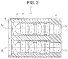
- FIG. 2 is a diagram in which an objective optical system according to the present embodiment is applied to an optical system of a stereoscopic-vision endoscope;
- FIG. 3 is a diagram showing a cross-sectional view of an arrangement of an objective optical system for endoscope according to an example 1;
- FIG. 4A , FIG. 4B , FIG. 4C , FIG. 4D , and FIG. 4E are aberration diagrams of the objective optical system for endoscope according to the example 1;
- FIG. 5 is a diagram showing a cross-sectional view of an arrangement of an objective optical system for endoscope according to an example 2;
- FIG. 6A , FIG. 6B , FIG. 6C , FIG. 6D , and FIG. 6E are aberration diagrams of the objective optical system for endoscope according to the example 2;
- FIG. 7 is a diagram showing a cross-sectional view of an arrangement of an objective optical system for endoscope according to an example 3;
- FIG. 8A , FIG. 8B , FIG. 8C , FIG. 8D , and FIG. 8E are aberration diagrams of the objective optical system for endoscope according to the example 3;
- FIG. 9 is a diagram showing a cross-sectional view of an arrangement of an objective optical system for endoscope according to an example 4.
- FIG. 10A , FIG. 10B , FIG. 10C , FIG. 10D , and FIG. 10E are aberration diagrams of the objective optical system for endoscope according to the example 4;
- FIG. 11 is a diagram showing a cross-sectional view of an arrangement of an objective optical system for endoscope according to an example 5;
- FIG. 12A , FIG. 12B , FIG. 12C , FIG. 12D , and FIG. 12E are aberration diagrams of the objective optical system for endoscope according to the example 5;
- FIG. 13 is a diagram showing a cross-sectional view of an arrangement of an objective optical system for endoscope according to an example 6;
- FIG. 14A , FIG. 14B , FIG. 14C , FIG. 14D , and FIG. 14E are aberration diagrams of the objective optical system for endoscope according to the example 6;
- FIG. 15 is a diagram showing a cross-sectional view of an arrangement of an objective optical system for endoscope according to an example 7;
- FIG. 16A , FIG. 16B , FIG. 16C , FIG. 16D , and FIG. 16E are aberration diagrams of the objective optical system for endoscope according to the example 7;
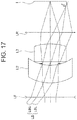
- FIG. 17 is a diagram showing an upper coma
- FIG. 18 is a diagram showing a lower coma.
- An objective optical system for endoscope of the present embodiment includes in order from an object side, a first group having a negative refractive power, an aperture stop, and a second group having a positive refractive power, wherein the first group includes in order from the object side, a negative meniscus lens having a convex surface directed toward the object side, and a positive lens having a convex surface directed toward the object side, and the second group includes in order from the object side, a predetermined lens and two positive lenses, and the negative meniscus lens has an aspheric surface, and the predetermined lens is a meniscus lens having a convex surface directed toward an image side, at least one of the two positive lenses is a cemented lens including a positive lens and a negative lens, and the following conditional expressions (1) and (2) are satisfied: 0.5 ⁇
- R 1 denotes a paraxial radius of curvature of a surface on the object side of the predetermined lens
- R 2 denotes a paraxial radius of curvature of a surface on an image side of the predetermined lens
- FL denotes a focal length of the overall objective optical system for endoscope.
- FIG. 1A and FIG. 1B are diagrams showing the objective optical system for endoscope of the present embodiment, where, FIG. 1A is a diagram showing an objective optical system for endoscope of a first embodiment, and FIG. 1B is a diagram showing an objective optical system for endoscope of a second embodiment.
- the objective optical system for endoscope of the present embodiment is an optical system having a wide angle of view. Therefore, in the objective optical system for endoscope of the present embodiment, for securing a wide angle of view, an optical system of a retro-focus type which is appropriate for widening the angle of view, is adopted.
- the objective optical system for endoscope of the first embodiment and the objective optical system for endoscope of the second embodiment include in order from an object side, a first group G 1 having a negative refractive power, an aperture stop S, and a second group G 2 having a positive refractive power.
- the first group G 1 includes in order from the object side, a negative meniscus lens L 1 having a convex surface directed toward the object side and a positive lens L 2 having a convex surface directed toward the object side.
- the negative meniscus lens L 1 has an aspheric surface.
- the barrel distortion be corrected favorably.
- a height of a principal light ray becomes the maximum at the negative meniscus lens in the first group. Therefore, by making the negative refractive power small in a peripheral portion of the first meniscus lens L 1 , it is possible to make gentle an angle of the principal light ray emerging from the negative meniscus lens L 1 . Accordingly, it is possible to reduce an amount of the barrel distortion that occurs.
- an aspheric surface is used in the negative meniscus lens L 1 . More specifically, a shape of the aspheric surface is such that the negative refractive power in the peripheral portion of the lens surface becomes weak.
- a method for weakening the negative refractive power in the peripheral portion As a method for weakening the negative refractive power in the peripheral portion, a method of making the negative refractive power in the peripheral portion weaker than the negative refractive power in a central portion, and a method of making the refractive power of the peripheral portion a positive refractive power are available.
- the second group G 2 includes the predetermined lens and the two positive lenses.
- the more specific arrangement of the second group G 2 differs in the objective optical system for endoscope of the first embodiment and the objective optical system for endoscope of the second embodiment.
- a second group G 2 includes in order from an object side, a predetermined lens L 3 , a positive lens CL, and a positive lens L 6 .
- the predetermined lens L 3 is a meniscus lens having a convex surface directed toward the image side.
- the positive lens CL includes a positive lens L 4 and a negative lens L 5 .
- a second group G 2 includes in order from an object side, a predetermined lens L 3 , a positive lens L 4 , and a positive lens CL.
- the predetermined lens L 3 is a meniscus lens having a convex surface directed toward the image side.
- the positive lens CL includes a positive lens L 5 and a negative lens L 6 .
- a cover glass C 1 and a cover glass C 2 are disposed on an image side of the second group G 2 .
- An image of an object is formed on an image-side surface of the cover glass C 2 . Therefore, an image pickup surface of an image pickup element is positioned on the image-side surface of the cover glass C 2 .
- the negative refractive power at the peripheral portion of the lens surface becomes smaller than the negative refractive power at the central portion of the lens surface.
- the refractive power at the peripheral portion of the lens surface is let to be the positive refractive power
- the refractive power of the first group G 1 becomes a positive refractive power
- the refractive power of the second group G 2 becomes a positive refractive power.
- the refractive power of the first group G 1 and the refractive power of the second group G 2 differ for a case of not using an aspheric surface and a case of using an aspheric surface.
- the refractive power of the first group G 1 and the refractive power of the second group G 2 are a positive refractive power and a negative refractive power respectively.
- both the refractive power of the first group G 1 and the refractive power of the second group G 2 are a positive refractive power.
- both the refractive power of the first group G 1 and the refractive power of the second group G 2 become a positive refractive power. Consequently, when an aspheric surface is used in the negative meniscus lens L 1 , it is possible to correct the distortion favorably. However, an astigmatism and a curvature of field accompanying the correction of distortion occur newly.
- a method of disposing the positive lens L 2 and the predetermined lens L 3 such that a lens arrangement becomes a lens arrangement of Gaussian type is available.
- the lens arrangement of Gaussian type a pair of meniscus lenses being disposed symmetrically with an aperture stop as a line of symmetry, the astigmatism and the curvature of field are corrected favorably.
- an optical system of Gaussian type each lens being a meniscus lens, it is difficult to make the refractive power large. Consequently, an optical system of Gaussian type is unfavorable for an optical system with a wide angle of view, such as endoscope, or in other words, an optical system that requires a large refractive power.
- any one of the positive lens L 2 and the predetermined lens L 3 is to be let to be a strong meniscus lens.
- a strong meniscus lens is a meniscus lens for which both a radius of curvature of an object-side surface and a radius of curvature of an image-side surface are small.
- FIG. 17 is a diagram showing an upper coma.
- FIG. 18 is a diagram showing a lower coma.
- the upper coma is a coma which occurs due to a light beam passing an upper side of an aperture out of the off-axis light beam
- the lower coma is a coma which occurs due to a light beam passing a lower side of an aperture out of the off-axis light beam.
- a lens LF and a lens LR are drawn in a simplified form as one line.
- a case in which the positive lens L 2 is let to be a strong meniscus lens will be described below.
- a light beam LBL passing through the lower side of the aperture is focused at an image plane I.
- a light beam LBU passing through the upper side of the aperture is focused on the object side of the image plane I as shown by an arrow.
- each lens in the cemented lens is to be made thick to some extent. For such reason, a thickness when the positive lens L 2 is let to be a cemented lens is susceptible to be more than a thickness when the positive lens L 2 is let to be a single lens.
- a space necessary for the cemented lens has to be secured in the first group G 1 .
- the thickness of the cemented lens is susceptible to be more than the thickness of the single lens. Therefore, securing the space in the first group G 1 becomes difficult as compared to a case of disposing the single lens.
- the optical system for endoscope has a feature such that an angle of view is extremely wide.
- an optical system with a wide angle of view as a distance between a negative lens in a first group and an aperture stop becomes long, a light-ray height at the negative lens in the first group becomes high.
- an aberration is susceptible to occur. Consequently, increasing the number of lenses in the first group G 1 , or in other words, letting the positive lens L 2 to be a cemented lens is not desirable.
- the predetermined lens L 3 is let to be a strong meniscus lens
- a light beam LBU passing the upper side of the aperture is focused at an image plane I.
- a light beam LBL passing through the lower side of the aperture is focused on the object side of the image plane I as shown by an arrow.
- the lower coma occurs.
- the upper coma also occurs slightly.
- the object-side surface of the predetermined lens L 3 has a large negative refractive power, the upper coma can be corrected at the object-side surface of the predetermined lens L 3 .
- a light-ray height becomes higher on the image side of the predetermined lens L 3 than a light-ray height at the predetermined lens L 3 . Consequently, by disposing a positive lens on the image side of the predetermined lens L 3 , it is possible to correct the lower coma by this positive lens.
- the positive lens is disposed nearest to image in the second group G 2 .
- the positive lens L 6 corresponds to the positive lens disposed nearest to image
- the positive lens CL corresponds to the positive lens disposed nearest to image. Accordingly, it is possible to prevent deterioration of the coma including a chromatic coma.
- a space for disposing a lens has to be secured between the second group G 2 and the cover glass C 1 . Therefore, in the objective optical system for endoscope of the present embodiment, a meniscus shape of the predetermined lens L 3 is enhanced, and the space for disposing the lens is secured.
- conditional expressions (1) and (2) are satisfied.
- conditional expression (1) When a value exceeds an upper limit value of conditional expression (1), an overall positive refractive power becomes large while the shape of the predetermined lens is a meniscus shape. Consequently, correction of the astigmatism becomes inadequate. When the value falls below a lower limit value of conditional expression (1), an overall negative refractive power becomes large while the shape of the predetermined lens is a meniscus shape. Consequently, correction of the astigmatism becomes excessive.
- conditional expression (1′) be satisfied instead of conditional expression (1).
- conditional expression (2′) be satisfied instead of conditional expression (2).
- conditional expression (3) be satisfied: 0.005 ⁇ ASP /FL ⁇ 0.08 (3)
- ⁇ ASP denotes an aspheric surface amount at a point of intersection of a principal light ray at the maximum image height and an aspheric surface
- FL denotes the focal length of the overall objective optical system for endoscope
- ⁇ ASP c ⁇ ⁇ ⁇ 2 1 + 1 - ( K + 1 ) ⁇ c 2 ⁇ ⁇ 2 + ⁇ i ⁇ A i ⁇ ⁇ i - c ⁇ ⁇ ⁇ 2 1 + 1 - c 2 ⁇ ⁇ 2 ( a )
- c denotes a reciprocal of a paraxial radius of curvature at the aspheric surface
- ⁇ denotes a distance from an optical axis up to the point of intersection, and a distance in a plane orthogonal to the optical axis including the point of intersection,
- K denotes a conical coefficient
- a i denotes an aspherical coefficient
- conditional expression (3) When a value exceeds an upper limit value of conditional expression (3), the aspheric surface amount with respect to the focal length of the overall system becomes excessively large. Consequently, the curvature of field cannot be corrected favorably.
- conditional expression (3) When the value falls below a lower limit value of conditional expression (3), the aspheric surface amount with respect to the focal length of the overall system becomes excessively small. Consequently, the distortion cannot be corrected favorably.
- conditional expression (3′) be satisfied instead of conditional expression (3) 0.02 ⁇ ASP /FL ⁇ 0.04 (3′)
- one of the positive lens and the negative lens in the cemented lens be an object-side lens positioned on the object side, and the other is an image-side lens positioned on the image side, and the following conditional expression (4) be satisfied: 4 ⁇
- Fc denotes a focal length at the cemented surface of the cemented lens
- FL denotes the focal length of the overall objective optical system for endoscope
- Rc denotes a paraxial radius of curvature of the cemented surface
- nd denotes a refractive index of the object-side lens for the d-line
- nd′ denotes a refractive index of the image-side lens for the d-line.
- conditional expression (4) When a value exceeds an upper limit value of conditional expression (4), the refractive power of the cemented surface with respect to the focal length of the overall system becomes excessively small. Consequently, the curvature of field cannot be corrected favorably.
- the value falls below a lower limit value of conditional expression (4) the refractive power of the cemented surface with respect to the focal length of the overall system becomes excessively large. Consequently, correction of the coma and correction of the curvature of field become excessive.
- conditional expression (4′) be satisfied instead of conditional expression (4).
- the two positive lenses are a cemented lens and a single lens, and the following conditional expression (5) be satisfied: 1.5 ⁇
- Ff denotes a focal length of a negative meniscus lens having the convex surface directed toward the object side
- Fr denotes a focal length of the single lens.
- conditional expression (5) When a value falls below a lower limit value of conditional expression (5), the negative meniscus lens having the convex surface directed toward the object side becomes large, and is not suited for the objective optical system for endoscope. When the value exceeds an upper limit value of conditional expression (5), correction of the barrel distortion becomes difficult.
- conditional expression (5′) be satisfied instead of conditional expression (5).
- the two positive lenses in the second group be disposed in order of a cemented lens of a positive lens and a negative lens, and a positive lens, and with this arrangement, to satisfy conditional expression (5) or (5′).
- the distortion is corrected favorably. Therefore, it is possible to use the objective optical system for endoscope of the present embodiment for an objective optical system of a stereoscopic-vision endoscope.
- the distortion is corrected favorably. Therefore, in a stereoscopic-vision endoscope using the objective optical system for endoscope of the present embodiment, it is possible to know accurately the distance up to a lesion part. Therefore, in a case of carrying out a treatment of a lesion part, it is possible to carry out the treatment efficiently.
- FIG. 2 is a diagram showing a front-end portion of a stereoscopic-vision endoscope of the present embodiment.
- a front-end portion 1 includes a front-end member 2 , an objective unit 3 , and an image pickup unit 4 .
- An interior of the front-end member 2 is provided with a circular cylindrical shaped through hole, and the objective unit 3 and the image pickup unit 4 are fitted into the through hole.
- Two objective optical systems 5 a and 5 b are disposed in the objective unit 3 .
- the objective optical system for endoscope of the first embodiment is used for each of the two objective optical systems 5 a and 5 b .
- a plane parallel plate 6 is disposed nearest to object of the two objective optical systems 5 a and 5 b .
- the plane parallel plate 6 is sapphire for example.
- sapphire is an extremely hard material, the sapphire is strong against an external impact. Therefore, a lens surface on the object side is hard to be scratched. By using sapphire, a projection of a scratch on image and an occurrence of flare due to the scratch are hard to occur.
- a glass material of the negative lens is not restricted to sapphire. When a crystalline material having a high hardness is used for the plane parallel plate 6 , a surface of the lens is hardly scratched.
- Two CCDs (charge coupled devices) 7 a and 7 b are disposed in the image pickup unit 4 .
- a center of an image pickup surface of the CCD 7 a is disposed at a position shifted in an upward direction in a paper surface from an optical axis of the objective optical system 5 a .
- a center of an image pickup surface of the CCD 7 b is disposed at a position shifted in a downward direction in the paper surface from an optical axis of the objective optical system 5 b.
- An amount of shift of the CCD 7 a and an amount of shift of the CCD 7 b are same. Accordingly, there is a parallax between an image acquired by the CCD 7 a and an image acquired by the CCD 7 b . As a result, a stereoscopic vision becomes possible.
- the objective optical system for endoscope of the first embodiment is used for each of the two objective optical systems 5 a and 5 b . Therefore, according to the stereoscopic-vision endoscope of the present embodiment, even in a case in which a flat surface is viewed stereoscopically, it can be identified as a flat surface. As a result, it is possible to know accurately the distance up to an object to be observed.
- FIG. 4A , FIG. 6A , FIG. 8A , FIG. 10A , FIG. 12A , FIG. 14A , and FIG. 16A show a spherical aberration (SA).
- FIG. 4B , FIG. 6B , FIG. 8B , FIG. 10B , FIG. 12B , FIG. 14B , and FIG. 16B show an astigmatism (AS).
- FIG. 4C , FIG. 6C , FIG. 8C , FIG. 10C , FIG. 12C , FIG. 14C , and FIG. 16C show a distortion (DT).
- FIG. 4D , FIG. 6D , FIG. 8D , FIG. 10D , FIG. 12D , FIG. 14D , and FIG. 16D show a chromatic aberration of magnification (CC).
- CC chromatic aberration of magnification
- a horizontal axis indicates an aberration amount.
- the unit of aberration amount is mm.
- the unit of aberration amount is %
- ⁇ denotes a half angle of view and the unit thereof is °
- FNO denotes an F-number.
- the unit of a wavelength of an aberration curve is nm.
- a vertical axis indicates an aperture ratio.
- An aberration curve in an X-direction (meridional direction) is indicated by a thin line, and an aberration curve in a Y-direction (sagittal direction) is indicated by a thick line.
- a negative meniscus lens having a convex surface directed toward an object side is disposed nearest to object of an objective optical system for endoscope.
- a plane parallel plate such as sapphire may be disposed on the object side of the negative meniscus lens.
- FIG. 3 is a diagram showing a cross-sectional view of an arrangement of the objective optical system for endoscope according to the example 1.
- FIG. 4A , FIG. 4B , FIG. 4C , FIG. 4D , and FIG. 4E are aberration diagrams of the objective optical system for endoscope according to the example 1.
- the objective optical system for endoscope of the example 1, as shown in FIG. 3 includes in order from an object side, a first group G 1 having a negative refractive power, an aperture stop S, and a second group G 2 having a positive refractive power.
- the first group G 1 includes a negative meniscus lens L 1 having a convex surface directed toward the object side and a planoconvex positive lens L 2 having a convex surface directed toward the object side.
- An aspheric surface is provided to an object-side surface of the negative meniscus lens L 1 .
- the second group G 2 includes a positive meniscus lens L 3 having a convex surface directed toward an image side, a biconvex positive lens L 4 , a negative meniscus lens L 5 having a convex surface directed toward the image side, and a positive meniscus lens L 6 having a convex surface directed toward the object side.
- the biconvex positive lens L 4 and the negative meniscus lens L 5 form a cemented lens having a positive refractive power.
- the positive meniscus lens L 3 is the predetermined lens.
- An optical filter F is disposed between the first group G 1 and the second group G 2 . Moreover, a cover glass C 1 and a cover glass C 2 are disposed on the image side of the second group G 2 .
- the cover glass C 2 is a cover glass of a solid image pickup element.
- FIG. 5 is a diagram showing a cross-sectional view of an arrangement of the objective optical system for endoscope according to the example 2.
- FIG. 6A , FIG. 6B , FIG. 6C , FIG. 6D , and FIG. 6E are aberration diagrams of the objective optical system for endoscope according to the example 2.
- the objective optical system for endoscope of the example 2 includes in order from an object side, a first group G 1 having a negative refractive power, an aperture stop S, and a second group G 2 having a positive refractive power.
- the first group G 1 includes a negative meniscus lens L 1 having a convex surface directed toward the object side and a planoconvex positive lens L 2 having a convex surface directed toward the object side.
- An aspheric surface is provided to an object-side surface of the negative meniscus lens L 1 .
- the second group G 2 includes a positive meniscus lens L 3 having a convex surface directed toward an image side, a negative meniscus lens L 4 having a convex surface directed toward the object side, a biconvex positive lens L 5 , and a biconvex positive lens L 6 .
- the negative meniscus lens L 4 and the biconvex positive lens L 5 form a cemented lens having a positive refractive power.
- the positive meniscus lens L 3 is the predetermined lens.
- An optical filter F is disposed between the first group G 1 and the second group G 2 . Moreover, a cover glass C 1 and a cover glass C 2 are disposed on the image side of the second group G 2 .
- the cover glass C 2 is a cover glass of a solid image pickup element.
- FIG. 7 is a diagram showing a cross-sectional view of an arrangement of the objective optical system for endoscope according to the example 3.
- FIG. 8A , FIG. 8B , FIG. 8C , FIG. 8D , and FIG. 8E are aberration diagrams of the objective optical system for endoscope according to the example 3.
- the objective optical system for endoscope of the example 3, as shown in FIG. 7 includes in order from an object side, a first group G 1 having a negative refractive power, an aperture stop S, and a second group G 2 having a positive refractive power.
- the first group G 1 includes a negative meniscus lens L 1 having a convex surface directed toward the object side and a planoconvex positive lens L 2 having a convex surface directed toward the object side.
- An aspheric surface is provided to an object-side surface of the negative meniscus lens L 1 .
- the second group G 2 includes a positive meniscus lens L 3 having a convex surface directed toward an image side, a biconvex positive lens L 4 , a biconvex positive lens L 5 , and a negative meniscus lens L 6 having a convex surface directed toward the image side.
- the biconvex positive lens L 5 and the negative meniscus lens L 6 form a cemented lens having a positive refractive power.
- the positive meniscus lens L 3 is the predetermined lens.
- An optical filter F is disposed between the first group G 1 and the second group G 2 . Moreover, a cover glass C 1 and a cover glass C 2 are disposed on the image side of the second group G 2 .
- the cover glass C 2 is a cover glass of a solid image pickup element.
- FIG. 9 is a diagram showing a cross-sectional view of an arrangement of the objective optical system for endoscope according to the example 4.
- FIG. 10A , FIG. 10B , FIG. 10C , FIG. 10D , and FIG. 10E are aberration diagrams of the objective optical system for endoscope according to the example 4.
- the objective optical system for endoscope of the example 4, as shown in FIG. 9 includes in order from an object side, a first group G 1 having a negative refractive power, an aperture stop S, and a second group G 2 having a positive refractive power.
- the first group G 1 includes a negative meniscus lens L 1 having a convex surface directed toward the object side and a planoconvex positive lens L 2 having a convex surface directed toward the object side.
- An aspheric surface is provided to an object-side surface of the negative meniscus lens L 1 .
- the second group G 2 includes a positive meniscus lens L 3 having a convex surface directed toward an image side, a biconvex positive lens L 4 , a negative meniscus lens L 5 having a convex surface directed toward the object side, and a biconvex positive lens L 6 .
- the negative meniscus lens L 5 and the biconvex positive lens L 6 form a cemented lens having a positive refractive power.
- the positive meniscus lens L 3 is the predetermined lens.
- An optical filter F is disposed between the first group G 1 and the second group G 2 . Moreover, a cover glass C 1 and a cover glass C 2 are disposed on the image side of the second group G 2 .
- the cover glass C 2 is a cover glass of a solid image pickup element.
- FIG. 11 is a diagram showing a cross-sectional view of an arrangement of the objective optical system for endoscope according to the example 5.
- FIG. 12A , FIG. 12B , FIG. 12C , FIG. 12D , and FIG. 12 E are aberration diagrams of the objective optical system for endoscope according to the example 5.
- the objective optical system for endoscope of the example 5, as shown in FIG. 11 includes in order from an object side, a first group G 1 having a negative refractive power, an aperture stop S, and a second group G 2 having a positive refractive power.
- the first group G 1 includes a negative meniscus lens L 1 having a convex surface directed toward the object side and a positive meniscus lens L 2 having a convex surface directed toward the object side.
- An aspheric surface is provided to an object-side surface of the negative meniscus lens L 1 .
- the second group G 2 includes a positive meniscus lens L 3 having a convex surface directed toward an image side, a negative meniscus lens L 4 having a convex surface directed toward the object side, a biconvex positive lens L 5 , and a positive meniscus lens L 6 having a convex surface directed toward the object side.
- the negative meniscus lens L 4 and the biconvex positive lens L 5 form a cemented lens having a positive refractive power.
- the positive meniscus lens L 3 is the predetermined lens.
- An optical filter F is disposed between the first group G 1 and the second group G 2 . Moreover, a cover glass C 1 and a cover glass C 2 are disposed on the image side of the second group G 2 .
- the cover glass C 2 is a cover glass of a solid image pickup element.
- FIG. 13 is a diagram showing a cross-sectional view of an arrangement of the objective optical system for endoscope according to the example 6.
- FIG. 14A , FIG. 14B , FIG. 14C , FIG. 14D , and FIG. 14E are aberration diagrams of the objective optical system for endoscope according to the example 6.
- the objective optical system for endoscope of the example 6, as shown in FIG. 13 includes in order from an object side, a first group G 1 having a negative refractive power, an aperture stop S, and a second group G 2 having a positive refractive power.
- the first group G 1 includes a negative meniscus lens L 1 having a convex surface directed toward the object side and a planoconvex positive lens L 2 having a convex surface directed toward the object side.
- An aspheric surface is provided to an object-side surface of the negative meniscus lens L 1 .
- the second group G 2 includes a positive meniscus lens L 3 having a convex surface directed toward an image side, a biconvex positive lens L 4 , a negative meniscus lens L 5 having a convex surface directed toward the image side, and a positive meniscus lens L 6 having a convex surface directed toward the object side.
- the biconvex positive lens L 4 and the negative meniscus lens L 5 form a cemented lens having a positive refractive power.
- the positive meniscus lens L 3 is the predetermined lens.
- An optical filter F is disposed between the first group G 1 and the second group G 2 . Moreover, a cover glass C 1 and a cover glass C 2 are disposed on the image side of the second group G 2 .
- the cover glass C 2 is a cover glass of a solid image pickup element.
- FIG. 15 is a diagram showing a cross-sectional view of an arrangement of the objective optical system for endoscope according to the example 7.
- FIG. 16A , FIG. 16B , FIG. 16C , FIG. 16D , and FIG. 16E are aberration diagrams of the objective optical system for endoscope according to the example 7.
- the objective optical system for endoscope of the example 7, as shown in FIG. 15 includes in order from an object side, a first group G 1 having a negative refractive power, an aperture stop S, and a second group G 2 having a positive refractive power.
- the first group G 1 includes a negative meniscus lens L 1 having a convex surface directed toward the object side and a planoconvex positive lens L 2 having a convex surface directed toward the object side.
- An aspheric surface is provided to an object-side surface of the negative meniscus lens L 1 .
- the second group G 2 includes a positive meniscus lens L 3 having a convex surface directed toward an image side, a biconvex positive lens L 4 , a negative meniscus lens L 5 having a convex surface directed toward the image side, and a positive meniscus lens L 6 having a convex surface directed toward the object side.
- the biconvex positive lens L 4 and the negative meniscus lens L 5 form a cemented lens having a positive refractive power.
- the positive meniscus lens L 3 is the predetermined lens.
- An optical filter F is disposed between the first group G 1 and the second group G 2 . Moreover, a cover glass C 1 and a cover glass C 2 are disposed on the image side of the second group G 2 .
- the cover glass C 2 is a cover glass of a solid image pickup element.
- Numerical data of each example described above is shown below.
- r denotes radius of curvature of each lens surface
- d denotes a distance between respective lens surfaces
- nd denotes a refractive index of each lens for a d-line
- ⁇ d denotes an Abbe number for each lens
- * denotes an aspherical surface
- FL denotes a focal length of the overall objective optical system for endoscope
- FNO. denotes an F number
- ⁇ denotes a half angle of view
- ⁇ denotes a point of intersection (aspheric surface amount) of a principal light ray with the maximum image height and an aspheric surface.
- conditional expressions (1) to (5) in each example are shown below.
- Example 1 Example 2 Example 3
- Example 4 (1)
- Conditional expression Example 5 Example 6
- Example 7 (1)
- the objective optical system for endoscope of the present embodiment it is possible to provide an objective optical system for endoscope in which, in addition to the distortion, the astigmatism and the curvature of field are corrected favorably.
- the present invention is useful for an objective optical system for endoscope in which, in addition to the distortion, the astigmatism and the curvature of field are corrected favorably.
Landscapes
- Physics & Mathematics (AREA)
- Optics & Photonics (AREA)
- General Physics & Mathematics (AREA)
- Health & Medical Sciences (AREA)
- Surgery (AREA)
- Life Sciences & Earth Sciences (AREA)
- General Health & Medical Sciences (AREA)
- Radiology & Medical Imaging (AREA)
- Astronomy & Astrophysics (AREA)
- Molecular Biology (AREA)
- Biomedical Technology (AREA)
- Heart & Thoracic Surgery (AREA)
- Medical Informatics (AREA)
- Engineering & Computer Science (AREA)
- Animal Behavior & Ethology (AREA)
- Nuclear Medicine, Radiotherapy & Molecular Imaging (AREA)
- Public Health (AREA)
- Veterinary Medicine (AREA)
- Biophysics (AREA)
- Pathology (AREA)
- Lenses (AREA)
Applications Claiming Priority (3)
| Application Number | Priority Date | Filing Date | Title |
|---|---|---|---|
| JP2015204693 | 2015-10-16 | ||
| JP2015-204693 | 2015-10-16 | ||
| PCT/JP2016/080246 WO2017065169A1 (ja) | 2015-10-16 | 2016-10-12 | 内視鏡用対物光学系 |
Related Parent Applications (1)
| Application Number | Title | Priority Date | Filing Date |
|---|---|---|---|
| PCT/JP2016/080246 Continuation WO2017065169A1 (ja) | 2015-10-16 | 2016-10-12 | 内視鏡用対物光学系 |
Publications (2)
| Publication Number | Publication Date |
|---|---|
| US20180231749A1 US20180231749A1 (en) | 2018-08-16 |
| US10564406B2 true US10564406B2 (en) | 2020-02-18 |
Family
ID=58517204
Family Applications (1)
| Application Number | Title | Priority Date | Filing Date |
|---|---|---|---|
| US15/950,393 Active 2037-01-09 US10564406B2 (en) | 2015-10-16 | 2018-04-11 | Objective optical system for endoscope |
Country Status (4)
| Country | Link |
|---|---|
| US (1) | US10564406B2 (ja) |
| JP (1) | JP6246433B2 (ja) |
| CN (1) | CN108139568B (ja) |
| WO (1) | WO2017065169A1 (ja) |
Cited By (1)
| Publication number | Priority date | Publication date | Assignee | Title |
|---|---|---|---|---|
| US11500366B2 (en) | 2019-03-26 | 2022-11-15 | Ge Aviation Systems Limited | Method and system for fusing disparate industrial asset event information |
Families Citing this family (3)
| Publication number | Priority date | Publication date | Assignee | Title |
|---|---|---|---|---|
| JP6576289B2 (ja) * | 2016-04-04 | 2019-09-18 | 富士フイルム株式会社 | 内視鏡用対物光学系および内視鏡 |
| WO2018235352A1 (ja) * | 2017-06-22 | 2018-12-27 | オリンパス株式会社 | 内視鏡用対物光学系 |
| CN114637098B (zh) * | 2022-04-08 | 2023-10-31 | 鹰利视医疗科技有限公司 | 一种8k腹腔镜的物镜结构 |
Citations (8)
| Publication number | Priority date | Publication date | Assignee | Title |
|---|---|---|---|---|
| JPH0455807A (ja) | 1990-06-26 | 1992-02-24 | Olympus Optical Co Ltd | 内視鏡対物レンズ |
| JPH08166537A (ja) | 1994-12-13 | 1996-06-25 | Konica Corp | レトロフォーカス型レンズ |
| US5625495A (en) | 1994-12-07 | 1997-04-29 | U.S. Precision Lens Inc. | Telecentric lens systems for forming an image of an object composed of pixels |
| JPH10148754A (ja) | 1996-11-19 | 1998-06-02 | Konica Corp | デジタルスチルカメラ |
| JPH11125767A (ja) | 1997-10-21 | 1999-05-11 | Asahi Optical Co Ltd | 撮影レンズ系 |
| JP2008107391A (ja) | 2006-10-23 | 2008-05-08 | Olympus Medical Systems Corp | 内視鏡対物光学系 |
| JP2009300797A (ja) | 2008-06-13 | 2009-12-24 | Fujinon Corp | 撮像レンズ及びカプセル型内視鏡 |
| WO2011152099A1 (ja) | 2010-06-01 | 2011-12-08 | Hoya株式会社 | 内視鏡用対物レンズ、及び内視鏡 |
Family Cites Families (4)
| Publication number | Priority date | Publication date | Assignee | Title |
|---|---|---|---|---|
| JP3369654B2 (ja) * | 1993-07-29 | 2003-01-20 | オリンパス光学工業株式会社 | 広角レンズ |
| JP3765500B2 (ja) * | 1993-12-24 | 2006-04-12 | オリンパス株式会社 | 内視鏡用対物レンズ |
| JP3723637B2 (ja) * | 1996-07-03 | 2005-12-07 | ペンタックス株式会社 | 撮影レンズ |
| CN104919353B (zh) * | 2013-04-22 | 2018-05-15 | 奥林巴斯株式会社 | 广角物镜光学系统 |
-
2016
- 2016-10-12 JP JP2017536052A patent/JP6246433B2/ja active Active
- 2016-10-12 WO PCT/JP2016/080246 patent/WO2017065169A1/ja active Application Filing
- 2016-10-12 CN CN201680060652.1A patent/CN108139568B/zh active Active
-
2018
- 2018-04-11 US US15/950,393 patent/US10564406B2/en active Active
Patent Citations (13)
| Publication number | Priority date | Publication date | Assignee | Title |
|---|---|---|---|---|
| JPH0455807A (ja) | 1990-06-26 | 1992-02-24 | Olympus Optical Co Ltd | 内視鏡対物レンズ |
| US5625495A (en) | 1994-12-07 | 1997-04-29 | U.S. Precision Lens Inc. | Telecentric lens systems for forming an image of an object composed of pixels |
| JPH11500834A (ja) | 1994-12-07 | 1999-01-19 | コーニング インコーポレイテッド | 画素からなる物体の像を形成するテレセントリックレンズシステム |
| JPH08166537A (ja) | 1994-12-13 | 1996-06-25 | Konica Corp | レトロフォーカス型レンズ |
| JPH10148754A (ja) | 1996-11-19 | 1998-06-02 | Konica Corp | デジタルスチルカメラ |
| US5999337A (en) | 1997-10-21 | 1999-12-07 | Asahi Kogaku Kogyo Kabushiki Kaisha | Lens system for electronic photography |
| JPH11125767A (ja) | 1997-10-21 | 1999-05-11 | Asahi Optical Co Ltd | 撮影レンズ系 |
| JP2008107391A (ja) | 2006-10-23 | 2008-05-08 | Olympus Medical Systems Corp | 内視鏡対物光学系 |
| US20080180809A1 (en) | 2006-10-23 | 2008-07-31 | Olympus Medical Systems Corp. | Objective optical system for an endoscope |
| US7466490B2 (en) * | 2006-10-23 | 2008-12-16 | Olympus Medical Systems Corp. | Objective optical system for an endoscope |
| JP2009300797A (ja) | 2008-06-13 | 2009-12-24 | Fujinon Corp | 撮像レンズ及びカプセル型内視鏡 |
| WO2011152099A1 (ja) | 2010-06-01 | 2011-12-08 | Hoya株式会社 | 内視鏡用対物レンズ、及び内視鏡 |
| US20130057666A1 (en) | 2010-06-01 | 2013-03-07 | Hoya Corporation | Objective lens for endoscope, and endoscope |
Non-Patent Citations (4)
| Title |
|---|
| Chinese Office Action dated Nov. 4, 2019 (and English translation thereof) issued in Chinese Application No. 201680060652.1. |
| International Preliminary Report on Patentability (IPRP) (and English language translation thereof) dated Apr. 26, 2018 issued in counterpart International Application No. PCT/JP2016/080246. |
| International Search Report (ISR) dated Dec. 13, 2016 issued in International Application No. PCT/JP2016/080246. |
| Written Opinion dated Dec. 13, 2016 issued in International Application No. PCT/JP2016/080246. |
Cited By (1)
| Publication number | Priority date | Publication date | Assignee | Title |
|---|---|---|---|---|
| US11500366B2 (en) | 2019-03-26 | 2022-11-15 | Ge Aviation Systems Limited | Method and system for fusing disparate industrial asset event information |
Also Published As
| Publication number | Publication date |
|---|---|
| JP6246433B2 (ja) | 2017-12-13 |
| US20180231749A1 (en) | 2018-08-16 |
| WO2017065169A1 (ja) | 2017-04-20 |
| JPWO2017065169A1 (ja) | 2017-10-12 |
| CN108139568B (zh) | 2020-07-24 |
| CN108139568A (zh) | 2018-06-08 |
Similar Documents
| Publication | Publication Date | Title |
|---|---|---|
| US10107993B2 (en) | Wide-angle optical system and image pickup apparatus using the same | |
| US9645383B2 (en) | Objective lens for endoscope and endoscope | |
| US10564406B2 (en) | Objective optical system for endoscope | |
| US9939627B2 (en) | Objective optical system for endoscope | |
| US9766437B2 (en) | Objective optical system for endoscope | |
| US11199682B2 (en) | Imaging optical system and image capturing apparatus | |
| US11079588B2 (en) | Relay optical system, and optical system for rigid endoscope and rigid endoscope using the same | |
| US9568726B2 (en) | Objective optical system for endoscope | |
| US11543647B2 (en) | Objective optical system for endoscope, endoscope, and image pickup unit | |
| US11067788B2 (en) | Bright relay optical system, and optical system for rigid endoscope and rigid endoscope using the same | |
| US10845586B2 (en) | Endoscope optical system | |
| US11903560B2 (en) | Objective optical system, image pickup apparatus, endoscope and endoscope system | |
| US11395578B2 (en) | Optical system for rigid endoscope and rigid endoscope | |
| US9804381B2 (en) | Endoscope objective optical system | |
| JP6230518B2 (ja) | 内視鏡対物光学系 | |
| US10739577B2 (en) | Objective optical system for endoscope | |
| US11150462B2 (en) | Objective optical system | |
| US11169369B2 (en) | Objective optical system for endoscope and endoscope | |
| US20220026702A1 (en) | Endoscope objective optical system and endoscope | |
| US11520135B2 (en) | Objective optical system, and optical system for rigid endoscope and rigid endoscope using the same | |
| WO2016114082A1 (ja) | 対物レンズ及びそれを備えた撮像装置 |
Legal Events
| Date | Code | Title | Description |
|---|---|---|---|
| AS | Assignment |
Owner name: OLYMPUS CORPORATION, JAPAN Free format text: ASSIGNMENT OF ASSIGNORS INTEREST;ASSIGNORS:NAMII, YASUSHI;SASAMOTO, TSUTOMU;REEL/FRAME:045505/0320 Effective date: 20180402 |
|
| FEPP | Fee payment procedure |
Free format text: ENTITY STATUS SET TO UNDISCOUNTED (ORIGINAL EVENT CODE: BIG.); ENTITY STATUS OF PATENT OWNER: LARGE ENTITY |
|
| STPP | Information on status: patent application and granting procedure in general |
Free format text: DOCKETED NEW CASE - READY FOR EXAMINATION |
|
| STPP | Information on status: patent application and granting procedure in general |
Free format text: NOTICE OF ALLOWANCE MAILED -- APPLICATION RECEIVED IN OFFICE OF PUBLICATIONS |
|
| STPP | Information on status: patent application and granting procedure in general |
Free format text: PUBLICATIONS -- ISSUE FEE PAYMENT VERIFIED |
|
| STCF | Information on status: patent grant |
Free format text: PATENTED CASE |
|
| MAFP | Maintenance fee payment |
Free format text: PAYMENT OF MAINTENANCE FEE, 4TH YEAR, LARGE ENTITY (ORIGINAL EVENT CODE: M1551); ENTITY STATUS OF PATENT OWNER: LARGE ENTITY Year of fee payment: 4 |