US1050676A - Seat. - Google Patents
Seat. Download PDFInfo
- Publication number
- US1050676A US1050676A US72161112A US1912721611A US1050676A US 1050676 A US1050676 A US 1050676A US 72161112 A US72161112 A US 72161112A US 1912721611 A US1912721611 A US 1912721611A US 1050676 A US1050676 A US 1050676A
- Authority
- US
- United States
- Prior art keywords
- seat
- tub
- body portion
- hooks
- bent
- Prior art date
- Legal status (The legal status is an assumption and is not a legal conclusion. Google has not performed a legal analysis and makes no representation as to the accuracy of the status listed.)
- Expired - Lifetime
Links
Images
Classifications
-
- A—HUMAN NECESSITIES
- A47—FURNITURE; DOMESTIC ARTICLES OR APPLIANCES; COFFEE MILLS; SPICE MILLS; SUCTION CLEANERS IN GENERAL
- A47K—SANITARY EQUIPMENT; ACCESSORIES THEREFOR, e.g. TOILET ACCESSORIES
- A47K3/00—Baths; Showers; Appurtenances therefor
- A47K3/12—Separate seats or body supports
- A47K3/122—Seats
Definitions
- IIIIIIIIIIIIIII D s'rzlgmz. 1 ,050,676'. Patented Jan. 14, 1913.
- This invent-ion relates to a seat which is intended to be used in connection with a wash tub so that the ordinary tub may be used as a bath tub.
- rlhe principal object of the invention is to provide an improved means for connecting the seat with the side of the tub so that the seat may be either suspended from the edge ot the tub by means of an improved type of hook, or may be supported by a spring clip carried upon the lower face of the seat.
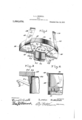
- Figure 1 is a perspective view of the seatlooking at the lower face.
- Fig. 2 is a sectional view through the side of the tub showing the seat suspended by the hooks.
- Fig. 3 is a view similar to Fig. 2 showing the seat supported upon the edge of the tub by t-he resilient clip.
- the seat comprises an arcuate body portion 10 which may be formed of any suitable material such as wood. rlhis body portion is provided with the curved edge so that it will fit into a tub as clearly shown in Fig. 2 with the curved edge resting against the side of the tub.
- a pair of plates 11 and 12 are secured to the lower face of the seat by means ot the screws 13, and each is provided with a hinge ear 14 through which a pin 15 passes.
- each hook is pivotally connected with each of the plates 11 and 12 and has its end portion 16 terminating in the hinge ears 17 through which the pin 15 passes thus pivotally mounting the hook.
- rlhe intermediate portion 18 of the hook extends at an angle to the end portion 16 so that when the hooks are turned as shown in Fig. 1 the upper por tions will converge and it closely against the curved side of the body portion.
- the upper end portion 19 of each hook is bent as shown in Fig. 1 and extends toward the center ot' the body portion so that the upper edge of the hook is parallel with the upper Specicaton of Letters Patent.
- a resilient clip is secured to the lower face of the body portion and is Jformed from a blank of spring metal doubled intermediate its length and then having its arms bent back'upon themselves to form the two plates 21 and 22 which are positioned in spaced relation. It should be noted, however, that these arms are close enough together so that when the seat is placed as shown in Fig. 3
- the two plates will be spread apart a certain amount thus causing them to grip the sides of the tub and thus hold the seat in place.
- the end portions of the blank are bent in opposite directions to form the feet 23 and 211 through which securing screws 25 are passed to securely attach the clip to the seat.
- the hooks When the seat is supported as shown in Fig. 8 the hooks will extend outwardly as shown in Fig. 3 and will thus form supports so that a cake of soap may be supported between the hooks and the lower face of the seat.
- the cake of soap will, therefore, not have to be left lioating in the water where it will be melted and wasted but will be held in a receptacle where it may be conveniently reached when it is desired to use it.
- the hooks will also be formed of spring metal so that they will grip the cake of soap and prevent it from slipping loose.
- a seat has, therefore, been provided which may be suspended within the tub from the upper edge by means of the hooks, or may be supported upon the upper edge of the tub by means of the spring clip, the hooks constituting a device for supporting a cake of soap.
- a seat comprising a body portion, a supporting clip secured to the lower face of said body port-ion and formed from a strip of resilient metal doubled intermediate its length and having its arms bent back upon themselves to form resilient plates, the end portions of the blank being bent in opposite directions to form feet, securing means passingthrough said feet and into said body portion to hold said clip in place, hinge ears carried by said body portion, and resilient Patented Jan. 14,1913.-
- a seat comprising a body portion, means for removably connecting said seat with the upper edge oiC a. tub, and resilient strips carried by said seat and being bent to form hooks extending beneath the seat in spaced relation thereto and forming an article receiving pocket.
- a body portion plates secured to said body portion and carrying hinge ears, strips each having one end portion provided with hinge ears, a pin pivotally connecting the hinge ears of said strip with the hinge ear ot said plate, said strip being bent at an angle intermediate its length whereby said strip will tit close against the bottom and side edge ot said body portion with its upper end por tions converging, and the upper end of said strip being bent at an angle to 'torni hooks having their upper edges extending parallel to the upper edge of said body portion.
Landscapes
- Health & Medical Sciences (AREA)
- Public Health (AREA)
- Epidemiology (AREA)
- General Health & Medical Sciences (AREA)
- Clamps And Clips (AREA)
Description
L. A. MISKELL.
IIIIIIIIIIIIIII D s'rzlgmz. 1 ,050,676'. Patented Jan. 14, 1913.
f4 ha 1 zo f l l if, 49 I 18 l la invrrnp sTATns PATENT OFFICE.
LEWIN A. MISKELL, 0F NELSONVILLE, OHIO.
SEAT.
To all whom t may concern Be it known that I, LnwIN A. MIsKnLL, a citizen of the United States, residing at Nelsonville, in the county of Athens and State of Ohio, have invented certain new and useful improvements in Seats, of which the following is a speciiication, reference being had therein to the accompanying drawing.
This invent-ion relates to a seat which is intended to be used in connection with a wash tub so that the ordinary tub may be used as a bath tub.
rlhe principal object of the invention is to provide an improved means for connecting the seat with the side of the tub so that the seat may be either suspended from the edge ot the tub by means of an improved type of hook, or may be supported by a spring clip carried upon the lower face of the seat.
This invention is illustrated in the accompanying drawings, wherein Figure 1 is a perspective view of the seatlooking at the lower face. Fig. 2 is a sectional view through the side of the tub showing the seat suspended by the hooks. Fig. 3 is a view similar to Fig. 2 showing the seat supported upon the edge of the tub by t-he resilient clip.
Referring to the accompanying drawings it will be seen that the seat comprises an arcuate body portion 10 which may be formed of any suitable material such as wood. rlhis body portion is provided with the curved edge so that it will fit into a tub as clearly shown in Fig. 2 with the curved edge resting against the side of the tub.
A pair of plates 11 and 12 are secured to the lower face of the seat by means ot the screws 13, and each is provided with a hinge ear 14 through which a pin 15 passes. A`
hook is pivotally connected with each of the plates 11 and 12 and has its end portion 16 terminating in the hinge ears 17 through which the pin 15 passes thus pivotally mounting the hook. rlhe intermediate portion 18 of the hook extends at an angle to the end portion 16 so that when the hooks are turned as shown in Fig. 1 the upper por tions will converge and it closely against the curved side of the body portion. The upper end portion 19 of each hook is bent as shown in Fig. 1 and extends toward the center ot' the body portion so that the upper edge of the hook is parallel with the upper Specicaton of Letters Patent.
Application filed September 21, 1912.
Serial No. 721,611.
tace of the body portion thus causing the two hooks to lie Hat upon the upper edge of the tub 20 as clearly shown in Fig. 2. From an inspection of Fig. 2 it will also be seen that these hooks tightly grip the upper edge of the tub so that there is no danger of the hooks working loose.
A resilient clip is secured to the lower face of the body portion and is Jformed from a blank of spring metal doubled intermediate its length and then having its arms bent back'upon themselves to form the two plates 21 and 22 which are positioned in spaced relation. It should be noted, however, that these arms are close enough together so that when the seat is placed as shown in Fig. 3
the two plates will be spread apart a certain amount thus causing them to grip the sides of the tub and thus hold the seat in place. The end portions of the blank are bent in opposite directions to form the feet 23 and 211 through which securing screws 25 are passed to securely attach the clip to the seat. When the seat is supported as shown in Fig. 8 the hooks will extend outwardly as shown in Fig. 3 and will thus form supports so that a cake of soap may be supported between the hooks and the lower face of the seat. The cake of soap will, therefore, not have to be left lioating in the water where it will be melted and wasted but will be held in a receptacle where it may be conveniently reached when it is desired to use it. It is, of course, obvious that the hooks will also be formed of spring metal so that they will grip the cake of soap and prevent it from slipping loose. A seat has, therefore, been provided which may be suspended within the tub from the upper edge by means of the hooks, or may be supported upon the upper edge of the tub by means of the spring clip, the hooks constituting a device for supporting a cake of soap.
Having thus described the invention, what is claimed as new, is
1. A seat comprising a body portion, a supporting clip secured to the lower face of said body port-ion and formed from a strip of resilient metal doubled intermediate its length and having its arms bent back upon themselves to form resilient plates, the end portions of the blank being bent in opposite directions to form feet, securing means passingthrough said feet and into said body portion to hold said clip in place, hinge ears carried by said body portion, and resilient Patented Jan. 14,1913.-
strips pivotally connected with said hinge ears and bent intermediate their length at an angle to their pivotally connected ends, the free ends of said strips being bent back upon themselves at an angle whereby said seat may be suspended VAfrom the upper edge of a tub by the hooked ends of said strips and supported upon the upper edge of a tub by said clip with said strips extending outwardly beneath said seat.
2. A seat comprising a body portion, means for removably connecting said seat with the upper edge oiC a. tub, and resilient strips carried by said seat and being bent to form hooks extending beneath the seat in spaced relation thereto and forming an article receiving pocket.
3. In a seat of the character described a body portion, plates secured to said body portion and carrying hinge ears, strips each having one end portion provided with hinge ears, a pin pivotally connecting the hinge ears of said strip with the hinge ear ot said plate, said strip being bent at an angle intermediate its length whereby said strip will tit close against the bottom and side edge ot said body portion with its upper end por tions converging, and the upper end of said strip being bent at an angle to 'torni hooks having their upper edges extending parallel to the upper edge of said body portion.
ln testimony whereof I hereunto atiix my signature in presence of two witnesses.
LEVIN E. M-ISKELL.
lVitnesses J. J. LANE, S. J. Hown.
Copies of this patent may be obtained for ve cents each, by addressing the Commissioner of Patents, Washington, I). C.
Priority Applications (1)
| Application Number | Priority Date | Filing Date | Title |
|---|---|---|---|
| US72161112A US1050676A (en) | 1912-09-21 | 1912-09-21 | Seat. |
Applications Claiming Priority (1)
| Application Number | Priority Date | Filing Date | Title |
|---|---|---|---|
| US72161112A US1050676A (en) | 1912-09-21 | 1912-09-21 | Seat. |
Publications (1)
| Publication Number | Publication Date |
|---|---|
| US1050676A true US1050676A (en) | 1913-01-14 |
Family
ID=3118940
Family Applications (1)
| Application Number | Title | Priority Date | Filing Date |
|---|---|---|---|
| US72161112A Expired - Lifetime US1050676A (en) | 1912-09-21 | 1912-09-21 | Seat. |
Country Status (1)
| Country | Link |
|---|---|
| US (1) | US1050676A (en) |
Cited By (1)
| Publication number | Priority date | Publication date | Assignee | Title |
|---|---|---|---|---|
| US2714923A (en) * | 1955-08-09 | Child s seat attachment for barber |
-
1912
- 1912-09-21 US US72161112A patent/US1050676A/en not_active Expired - Lifetime
Cited By (1)
| Publication number | Priority date | Publication date | Assignee | Title |
|---|---|---|---|---|
| US2714923A (en) * | 1955-08-09 | Child s seat attachment for barber |
Similar Documents
| Publication | Publication Date | Title |
|---|---|---|
| US644080A (en) | Combined sponge and soap holder. | |
| US1201159A (en) | Tool-holder. | |
| US1760268A (en) | Sink-cleaning implement | |
| US378201A (en) | Goat-hook | |
| US405955A (en) | Bracket for papers | |
| US754369A (en) | Seat for bath-tubs. | |
| US274672A (en) | Adjustable hook | |
| US362189A (en) | Lewis stein | |
| US992173A (en) | Toilet-pad. | |
| US173694A (en) | Improvement in shoe-exhibiting devices | |
| US788252A (en) | Napkin-holder. | |
| US260160A (en) | Hat-holder | |
| US416280A (en) | Shaving-paper holder | |
| US450462A (en) | Soap-dish and brush-holder for scru b-buckets | |
| US966692A (en) | Mop-holder. | |
| US770953A (en) | Rule-holder. | |
| US1122961A (en) | Match-scratcher. | |
| US622199A (en) | Plumber s tack | |
| US930814A (en) | Skirt and garment supporter. | |
| US602243A (en) | X l louis rybold | |
| US1211485A (en) | Mop-holder. | |
| US644417A (en) | Skirt-supporter. | |
| US1017511A (en) | Trousers-leg holder. | |
| US877637A (en) | Holder for hooks and eyes. | |
| US548020A (en) | Dress-hook |