US10326831B2 - Signal generating method, signal generating unit, and non-transitory recording medium storing computer program - Google Patents
Signal generating method, signal generating unit, and non-transitory recording medium storing computer program Download PDFInfo
- Publication number
- US10326831B2 US10326831B2 US15/647,300 US201715647300A US10326831B2 US 10326831 B2 US10326831 B2 US 10326831B2 US 201715647300 A US201715647300 A US 201715647300A US 10326831 B2 US10326831 B2 US 10326831B2
- Authority
- US
- United States
- Prior art keywords
- receiver
- diagram illustrating
- transmitter
- signal
- image
- Prior art date
- Legal status (The legal status is an assumption and is not a legal conclusion. Google has not performed a legal analysis and makes no representation as to the accuracy of the status listed.)
- Active
Links
Images


Classifications
-
- H—ELECTRICITY
- H04—ELECTRIC COMMUNICATION TECHNIQUE
- H04L—TRANSMISSION OF DIGITAL INFORMATION, e.g. TELEGRAPHIC COMMUNICATION
- H04L67/00—Network arrangements or protocols for supporting network services or applications
- H04L67/01—Protocols
- H04L67/10—Protocols in which an application is distributed across nodes in the network
- H04L67/1001—Protocols in which an application is distributed across nodes in the network for accessing one among a plurality of replicated servers
- H04L67/1004—Server selection for load balancing
- H04L67/1006—Server selection for load balancing with static server selection, e.g. the same server being selected for a specific client
-
- G—PHYSICS
- G01—MEASURING; TESTING
- G01R—MEASURING ELECTRIC VARIABLES; MEASURING MAGNETIC VARIABLES
- G01R27/00—Arrangements for measuring resistance, reactance, impedance, or electric characteristics derived therefrom
- G01R27/02—Measuring real or complex resistance, reactance, impedance, or other two-pole characteristics derived therefrom, e.g. time constant
- G01R27/04—Measuring real or complex resistance, reactance, impedance, or other two-pole characteristics derived therefrom, e.g. time constant in circuits having distributed constants, e.g. having very long conductors or involving high frequencies
-
- G—PHYSICS
- G06—COMPUTING; CALCULATING OR COUNTING
- G06F—ELECTRIC DIGITAL DATA PROCESSING
- G06F16/00—Information retrieval; Database structures therefor; File system structures therefor
- G06F16/90—Details of database functions independent of the retrieved data types
- G06F16/95—Retrieval from the web
- G06F16/958—Organisation or management of web site content, e.g. publishing, maintaining pages or automatic linking
-
- G06F17/3089—
-
- H—ELECTRICITY
- H04—ELECTRIC COMMUNICATION TECHNIQUE
- H04B—TRANSMISSION
- H04B10/00—Transmission systems employing electromagnetic waves other than radio-waves, e.g. infrared, visible or ultraviolet light, or employing corpuscular radiation, e.g. quantum communication
- H04B10/11—Arrangements specific to free-space transmission, i.e. transmission through air or vacuum
- H04B10/114—Indoor or close-range type systems
- H04B10/116—Visible light communication
-
- H—ELECTRICITY
- H04—ELECTRIC COMMUNICATION TECHNIQUE
- H04B—TRANSMISSION
- H04B10/00—Transmission systems employing electromagnetic waves other than radio-waves, e.g. infrared, visible or ultraviolet light, or employing corpuscular radiation, e.g. quantum communication
- H04B10/50—Transmitters
-
- H—ELECTRICITY
- H04—ELECTRIC COMMUNICATION TECHNIQUE
- H04B—TRANSMISSION
- H04B3/00—Line transmission systems
- H04B3/02—Details
- H04B3/04—Control of transmission; Equalising
- H04B3/14—Control of transmission; Equalising characterised by the equalising network used
-
- H—ELECTRICITY
- H04—ELECTRIC COMMUNICATION TECHNIQUE
- H04L—TRANSMISSION OF DIGITAL INFORMATION, e.g. TELEGRAPHIC COMMUNICATION
- H04L27/00—Modulated-carrier systems
- H04L27/26—Systems using multi-frequency codes
- H04L27/2601—Multicarrier modulation systems
- H04L27/2602—Signal structure
-
- H—ELECTRICITY
- H04—ELECTRIC COMMUNICATION TECHNIQUE
- H04L—TRANSMISSION OF DIGITAL INFORMATION, e.g. TELEGRAPHIC COMMUNICATION
- H04L67/00—Network arrangements or protocols for supporting network services or applications
- H04L67/01—Protocols
- H04L67/02—Protocols based on web technology, e.g. hypertext transfer protocol [HTTP]
Definitions
- the present disclosure relates to a visible light signal generating method, a signal generating unit, and a non-transitory recording medium having a computer program stored thereon.
- HEMS home energy management system
- IP internet protocol
- LAN wireless local area network
- Patent Literature (PTL) 1 discloses a technique of efficiently establishing communication between devices among limited optical spatial transmission devices which transmit information to a free space using light, by performing communication using plural single color light sources of illumination light.
- the conventional method is limited to a case in which a device to which the method is applied has three color light sources such as an illuminator.
- one non-limiting and exemplary embodiment provides a signal generating method, a signal generating unit, and a non-transitory recording medium having a computer program stored thereon for a visible light signal enabling communication between various devices.
- the techniques disclosed here feature a signal generating method for generating a visible light signal transmitted by way of a luminance change of a light source included in a transmitter, the method including: determining, as a method for transmitting the visible light signal from the transmitter, one of a single-frame transmitting method for transmitting data as one frame and a multiple-frame transmitting method for transmitting the data while dividing the data into a plurality of frames; when the multiple-frame transmitting method is determined to be the method for transmitting the visible light signal, generating partition type information indicating a type of data to be transmitted, and generating combination data by adding the partition type information to the data to be transmitted; generating the plurality of frames, each of which includes each of a plurality of data parts, by dividing the combination data into the plurality of data parts; and generating the visible light signal by adding a preamble, being data indicating a head of a frame, to the head of each of the plurality of frames.
- the present disclosure can provide the signal generating method, the signal generating unit, and the non-transitory recording medium having the computer program stored thereon for the visible light signal enabling the communication between various devices other than lightings.
- FIG. 1 is a diagram illustrating an example of an observation method of luminance of a light emitting unit in Embodiment 1;
- FIG. 2 is a diagram illustrating an example of an observation method of luminance of a light emitting unit in Embodiment 1;
- FIG. 3 is a diagram illustrating an example of an observation method of luminance of a light emitting unit in Embodiment 1;
- FIG. 4 is a diagram illustrating an example of an observation method of luminance of a light emitting unit in Embodiment 1;
- FIG. 5A is a diagram illustrating an example of an observation method of luminance of a light emitting unit in Embodiment 1;
- FIG. 5B is a diagram illustrating an example of an observation method of luminance of a light emitting unit in Embodiment 1;
- FIG. 5C is a diagram illustrating an example of an observation method of luminance of a light emitting unit in Embodiment 1;
- FIG. 5D is a diagram illustrating an example of an observation method of luminance of a light emitting unit in Embodiment 1;
- FIG. 5E is a diagram illustrating an example of an observation method of luminance of a light emitting unit in Embodiment 1;
- FIG. 5F is a diagram illustrating an example of an observation method of luminance of a light emitting unit in Embodiment 1;
- FIG. 5G is a diagram illustrating an example of an observation method of luminance of a light emitting unit in Embodiment 1;
- FIG. 5H is a diagram illustrating an example of an observation method of luminance of a light emitting unit in Embodiment 1;
- FIG. 6A is a flowchart of an information communication method in Embodiment 1;
- FIG. 6B is a block diagram of an information communication device in Embodiment 1;
- FIG. 7 is a diagram illustrating an example of each mode of a receiver in Embodiment 2.
- FIG. 8 is a diagram illustrating an example of imaging operation of a receiver in Embodiment 2.
- FIG. 9 is a diagram illustrating another example of imaging operation of a receiver in Embodiment 2.
- FIG. 10A is a diagram illustrating another example of imaging operation of a receiver in Embodiment 2;
- FIG. 10B is a diagram illustrating another example of imaging operation of a receiver in Embodiment 2;
- FIG. 10C is a diagram illustrating another example of imaging operation of a receiver in Embodiment 2.
- FIG. 11A is a diagram illustrating an example of camera arrangement of a receiver in Embodiment 2;
- FIG. 11B is a diagram illustrating another example of camera arrangement of a receiver in Embodiment 2;
- FIG. 12 is a diagram illustrating an example of display operation of a receiver in Embodiment 2;
- FIG. 13 is a diagram illustrating an example of display operation of a receiver in Embodiment 2;
- FIG. 14 is a diagram illustrating an example of operation of a receiver in Embodiment 2.
- FIG. 15 is a diagram illustrating another example of operation of a receiver in Embodiment 2.
- FIG. 16 is a diagram illustrating another example of operation of a receiver in Embodiment 2.
- FIG. 17 is a diagram illustrating another example of operation of a receiver in Embodiment 2.
- FIG. 18 is a diagram illustrating another example of operation of a receiver in Embodiment 2.
- FIG. 19 is a diagram illustrating another example of operation of a receiver in Embodiment 2.
- FIG. 20 is a diagram illustrating another example of operation of a receiver in Embodiment 2.
- FIG. 21 is a diagram illustrating an example of operation of a receiver, a transmitter, and a server in Embodiment 2;
- FIG. 22 is a diagram illustrating another example of operation of a receiver in Embodiment 2.
- FIG. 23 is a diagram illustrating another example of operation of a receiver in Embodiment 2.
- FIG. 24 is a diagram illustrating an example of initial setting of a receiver in Embodiment 2;
- FIG. 25 is a diagram illustrating another example of operation of a receiver in Embodiment 2.
- FIG. 26 is a diagram illustrating another example of operation of a receiver in Embodiment 2.
- FIG. 27 is a diagram illustrating another example of operation of a receiver in Embodiment 2.
- FIG. 28 is a diagram illustrating another example of operation of a receiver in Embodiment 2.
- FIG. 29 is a diagram illustrating another example of operation of a receiver in Embodiment 2.
- FIG. 30 is a diagram illustrating another example of operation of a receiver in Embodiment 2.
- FIG. 31A is a diagram illustrating a pen used to operate a receiver in Embodiment 2;
- FIG. 31B is a diagram illustrating operation of a receiver using a pen in Embodiment 2;
- FIG. 32 is a diagram illustrating an example of appearance of a receiver in Embodiment 2.
- FIG. 33 is a diagram illustrating another example of appearance of a receiver in Embodiment 2.
- FIG. 34 is a diagram illustrating another example of operation of a receiver in Embodiment 2.
- FIG. 35A is a diagram illustrating another example of operation of a receiver in Embodiment 2.
- FIG. 35B is a diagram illustrating an example of application using a receiver in Embodiment 2;
- FIG. 36A is a diagram illustrating another example of operation of a receiver in Embodiment 2.
- FIG. 36B is a diagram illustrating an example of application using a receiver in Embodiment 2;
- FIG. 37A is a diagram illustrating an example of operation of a transmitter in Embodiment 2.
- FIG. 37B is a diagram illustrating another example of operation of a transmitter in Embodiment 2.
- FIG. 38 is a diagram illustrating another example of operation of a transmitter in Embodiment 2.
- FIG. 39 is a diagram illustrating another example of operation of a transmitter in Embodiment 2.
- FIG. 40 is a diagram illustrating an example of communication form between a plurality of transmitters and a receiver in Embodiment 2;
- FIG. 41 is a diagram illustrating an example of operation of a plurality of transmitters in Embodiment 2;
- FIG. 42 is a diagram illustrating another example of communication form between a plurality of transmitters and a receiver in Embodiment 2;
- FIG. 43 is a diagram illustrating another example of operation of a receiver in Embodiment 2.
- FIG. 44 is a diagram illustrating an example of application of a receiver in Embodiment 2.
- FIG. 45 is a diagram illustrating an example of application of a receiver in Embodiment 2.
- FIG. 46 is a diagram illustrating an example of application of a receiver in Embodiment 2.
- FIG. 47 is a diagram illustrating an example of application of a transmitter in Embodiment 2.
- FIG. 48 is a diagram illustrating an example of application of a transmitter in Embodiment 2.
- FIG. 49 is a diagram illustrating an example of application of a reception method in Embodiment 2;
- FIG. 50 is a diagram illustrating an example of application of a transmitter in Embodiment 2.
- FIG. 51 is a diagram illustrating an example of application of a transmitter in Embodiment 2.
- FIG. 52 is a diagram illustrating an example of application of a transmitter in Embodiment 2.
- FIG. 53 is a diagram illustrating another example of operation of a receiver in Embodiment 2.
- FIG. 54 is a flowchart illustrating an example of operation of a receiver in Embodiment 3.
- FIG. 55 is a flowchart illustrating another example of operation of a receiver in Embodiment 3.
- FIG. 56A is a block diagram illustrating an example of a transmitter in Embodiment 3.
- FIG. 56B is a block diagram illustrating another example of a transmitter in Embodiment 3.
- FIG. 57 is a diagram illustrating an example of a structure of a system including a plurality of transmitters in Embodiment 3;
- FIG. 58 is a block diagram illustrating another example of a transmitter in Embodiment 3.
- FIG. 59A is a diagram illustrating an example of a transmitter in Embodiment 3.
- FIG. 59B is a diagram illustrating an example of a transmitter in Embodiment 3.
- FIG. 59C is a diagram illustrating an example of a transmitter in Embodiment 3.
- FIG. 60A is a diagram illustrating an example of a transmitter in Embodiment 3.
- FIG. 60B is a diagram illustrating an example of a transmitter in Embodiment 3.
- FIG. 61 is a diagram illustrating an example of processing operation of a receiver, a transmitter, and a server in Embodiment 3;
- FIG. 62 is a diagram illustrating an example of processing operation of a receiver, a transmitter, and a server in Embodiment 3;
- FIG. 63 is a diagram illustrating an example of processing operation of a receiver, a transmitter, and a server in Embodiment 3;
- FIG. 64A is a diagram for describing synchronization between a plurality of transmitters in Embodiment 3;
- FIG. 64B is a diagram for describing synchronization between a plurality of transmitters in Embodiment 3;
- FIG. 65 is a diagram illustrating an example of operation of a transmitter and a receiver in Embodiment 3;
- FIG. 66 is a diagram illustrating an example of operation of a transmitter and a receiver in Embodiment 3;
- FIG. 67 is a diagram illustrating an example of operation of a transmitter, a receiver, and a server in Embodiment 3;
- FIG. 68 is a diagram illustrating an example of operation of a transmitter and a receiver in Embodiment 3;
- FIG. 69 is a diagram illustrating an example of appearance of a receiver in Embodiment 3.
- FIG. 70 is a diagram illustrating an example of operation of a transmitter, a receiver, and a server in Embodiment 3;
- FIG. 71 is a diagram illustrating an example of operation of a transmitter and a receiver in Embodiment 3;
- FIG. 72 is a diagram illustrating an example of operation of a transmitter and a receiver in Embodiment 3;
- FIG. 73 is a diagram illustrating an example of operation of a transmitter and a receiver in Embodiment 3;
- FIG. 74 is a diagram illustrating an example of operation of a transmitter and a receiver in Embodiment 3;
- FIG. 75A is a diagram illustrating another example of a structure of information transmitted by a transmitter in Embodiment 3;
- FIG. 75B is a diagram illustrating another example of a structure of information transmitted by a transmitter in Embodiment 3;
- FIG. 76 is a diagram illustrating an example of a 4-value PPM modulation scheme by a transmitter in Embodiment 3;
- FIG. 77 is a diagram illustrating an example of a PPM modulation scheme by a transmitter in Embodiment 3;
- FIG. 78 is a diagram illustrating an example of a PPM modulation scheme by a transmitter in Embodiment 3;
- FIG. 79A is a diagram illustrating an example of a luminance change pattern corresponding to a header (preamble part) in Embodiment 3;
- FIG. 79B is a diagram illustrating an example of a luminance change pattern in Embodiment 3.
- FIG. 80A is a diagram illustrating an example of a luminance change pattern in Embodiment 3.
- FIG. 80B is a diagram illustrating an example of a luminance change pattern in Embodiment 3.
- FIG. 81 is a diagram illustrating an example of operation of a receiver in an in-front-of-store situation in Embodiment 4;
- FIG. 82 is a diagram illustrating another example of operation of a receiver in an in-front-of-store situation in Embodiment 4;
- FIG. 83 is a diagram illustrating an example of next operation of a receiver in an in-front-of-store situation in Embodiment 4;
- FIG. 84 is a diagram illustrating an example of next operation of a receiver in an in-front-of-store situation in Embodiment 4;
- FIG. 85 is a diagram illustrating an example of next operation of a receiver in an in-front-of-store situation in Embodiment 4.
- FIG. 86 is a diagram illustrating an example of operation of a display device in an in-front-of-store situation in Embodiment 4.
- FIG. 87 is a diagram illustrating an example of next operation of a display device in an in-front-of-store situation in Embodiment 4;
- FIG. 88 is a diagram illustrating an example of next operation of a display device in an in-front-of-store situation in Embodiment 4;
- FIG. 89 is a diagram illustrating an example of next operation of a receiver in an in-front-of-store situation in Embodiment 4.
- FIG. 90 is a diagram illustrating an example of next operation of a receiver in an in-front-of-store situation in Embodiment 4.
- FIG. 91 is a diagram illustrating an example of next operation of a receiver in an in-front-of-store situation in Embodiment 4;
- FIG. 92 is a diagram illustrating an example of next operation of a receiver in an in-front-of-store situation in Embodiment 4;
- FIG. 93 is a diagram illustrating an example of next operation of a receiver in an in-front-of-store situation in Embodiment 4.
- FIG. 94 is a diagram illustrating an example of next operation of a receiver in an in-front-of-store situation in Embodiment 4.
- FIG. 95 is a diagram illustrating an example of operation of a receiver in a store search situation in Embodiment 4.
- FIG. 96 is a diagram illustrating an example of next operation of a receiver in a store search situation in Embodiment 4.
- FIG. 97 is a diagram illustrating an example of next operation of a receiver in a store search situation in Embodiment 4.
- FIG. 98 is a diagram illustrating an example of operation of a receiver in a movie advertisement situation in Embodiment 4.
- FIG. 99 is a diagram illustrating an example of next operation of a receiver in a movie advertisement situation in Embodiment 4.
- FIG. 100 is a diagram illustrating an example of next operation of a receiver in a movie advertisement situation in Embodiment 4.
- FIG. 101 is a diagram illustrating an example of next operation of a receiver in a movie advertisement situation in Embodiment 4.
- FIG. 102 is a diagram illustrating an example of operation of a receiver in a museum situation in Embodiment 4.
- FIG. 103 is a diagram illustrating an example of next operation of a receiver in a museum situation in Embodiment 4;
- FIG. 104 is a diagram illustrating an example of next operation of a receiver in a museum situation in Embodiment 4.
- FIG. 105 is a diagram illustrating an example of next operation of a receiver in a museum situation in Embodiment 4.
- FIG. 106 is a diagram illustrating an example of next operation of a receiver in a museum situation in Embodiment 4.
- FIG. 107 is a diagram illustrating an example of next operation of a receiver in a museum situation in Embodiment 4.
- FIG. 108 is a diagram illustrating an example of operation of a receiver in a bus stop situation in Embodiment 4.
- FIG. 109 is a diagram illustrating an example of next operation of a receiver in a bus stop situation in Embodiment 4.
- FIG. 110 is a diagram for describing imaging in Embodiment 4.
- FIG. 111 is a diagram for describing transmission and imaging in Embodiment 4.
- FIG. 112 is a diagram for describing transmission in Embodiment 4.
- FIG. 113 is a diagram illustrating an example of operation of a transmitter in Embodiment 5.
- FIG. 114 is a diagram illustrating an example of operation of a transmitter in Embodiment 5.
- FIG. 115 is a diagram illustrating an example of operation of a transmitter in Embodiment 5.
- FIG. 116 is a diagram illustrating an example of operation of a transmitter and a receiver in Embodiment 5;
- FIG. 117 is a diagram illustrating an example of operation of a receiver in Embodiment 5.
- FIG. 118 is a diagram illustrating an example of operation of a receiver in Embodiment 5.
- FIG. 119 is a diagram illustrating an example of operation of a system including a transmitter, a receiver, and a server in Embodiment 5;
- FIG. 120 is a block diagram illustrating a structure of a transmitter in Embodiment 5.
- FIG. 121 is a block diagram illustrating a structure of a receiver in Embodiment 5.
- FIG. 122 is a diagram illustrating an example of operation of a transmitter in Embodiment 5.
- FIG. 123 is a diagram illustrating an example of operation of a transmitter in Embodiment 5.
- FIG. 124 is a diagram illustrating an example of operation of a transmitter in Embodiment 5.
- FIG. 125 is a diagram illustrating an example of operation of a transmitter in Embodiment 5.
- FIG. 126 is a diagram illustrating an example of operation of a transmitter in Embodiment 5.
- FIG. 127 is a diagram illustrating an example of operation of a transmitter in Embodiment 5.
- FIG. 128 is a diagram illustrating an example of operation of a transmitter in Embodiment 5.
- FIG. 129 is a diagram illustrating an example of operation of a transmitter and a receiver in Embodiment 5;
- FIG. 130 is a diagram illustrating an example of operation of a transmitter and a receiver in Embodiment 5;
- FIG. 131 is a diagram illustrating an example of operation of a transmitter and a receiver in Embodiment 5;
- FIG. 132 is a diagram illustrating an example of operation of a transmitter and a receiver in Embodiment 5;
- FIG. 133 is a diagram illustrating an example of operation of a transmitter and a receiver in Embodiment 5;
- FIG. 134 is a diagram illustrating an example of operation of a transmitter and a receiver in Embodiment 5;
- FIG. 135 is a diagram illustrating an example of operation of a transmitter and a receiver in Embodiment 5;
- FIG. 136 is a diagram illustrating an example of operation of a transmitter and a receiver in Embodiment 5;
- FIG. 137 is a diagram illustrating an example of operation of a transmitter and a receiver in Embodiment 5;
- FIG. 138 is a diagram illustrating an example of operation of a transmitter and a receiver in Embodiment 5;
- FIG. 139 is a diagram illustrating an example of operation of a transmitter and a receiver in Embodiment 5;
- FIG. 140 is a diagram illustrating an example of operation of a transmitter and a receiver in Embodiment 5;
- FIG. 141 is a diagram illustrating an example of operation of a transmitter and a receiver in Embodiment 5;
- FIG. 142 is a diagram illustrating a coding scheme in Embodiment 5.
- FIG. 143 is a diagram illustrating a coding scheme that can receive light even in the case of capturing an image in an oblique direction in Embodiment 5;
- FIG. 144 is a diagram illustrating a coding scheme that differs in information amount depending on distance in Embodiment 5;
- FIG. 145 is a diagram illustrating a coding scheme that differs in information amount depending on distance in Embodiment 5;
- FIG. 146 is a diagram illustrating a coding scheme that divides data in Embodiment 5.
- FIG. 147 is a diagram illustrating an opposite-phase image insertion effect in Embodiment 5.
- FIG. 148 is a diagram illustrating an opposite-phase image insertion effect in Embodiment 5.
- FIG. 149 is a diagram illustrating a superresolution process in Embodiment 5.
- FIG. 150 is a diagram illustrating a display indicating visible light communication capability in Embodiment 5.
- FIG. 151 is a diagram illustrating information obtainment using a visible light communication signal in Embodiment 5;
- FIG. 152 is a diagram illustrating a data format in Embodiment 5.
- FIG. 153 is a diagram illustrating reception by estimating a stereoscopic shape in Embodiment 5.
- FIG. 154 is a diagram illustrating reception by estimating a stereoscopic shape in Embodiment 5.
- FIG. 155 is a diagram illustrating stereoscopic projection in Embodiment 5.
- FIG. 156 is a diagram illustrating stereoscopic projection in Embodiment 5.
- FIG. 157 is a diagram illustrating an example of operation of a transmitter and a receiver in Embodiment 5;
- FIG. 158 is a diagram illustrating an example of operation of a transmitter and a receiver in Embodiment 5;
- FIG. 159 is a diagram illustrating an example of a transmission signal in Embodiment 6;
- FIG. 160 is a diagram illustrating an example of a transmission signal in Embodiment 6;
- FIG. 161A is a diagram illustrating an example of an image (bright line image) captured by a receiver in Embodiment 6;
- FIG. 161B is a diagram illustrating an example of an image (bright line image) captured by a receiver in Embodiment 6;
- FIG. 161C is a diagram illustrating an example of an image (bright line image) captured by a receiver in Embodiment 6.
- FIG. 162A is a diagram illustrating an example of an image (bright line image) captured by a receiver in Embodiment 6;
- FIG. 162B is a diagram illustrating an example of an image (bright line image) captured by a receiver in Embodiment 6;
- FIG. 163A is a diagram illustrating an example of an image (bright line image) captured by a receiver in Embodiment 6;
- FIG. 163B is a diagram illustrating an example of an image (bright line image) captured by a receiver in Embodiment 6;
- FIG. 163C is a diagram illustrating an example of an image (bright line image) captured by a receiver in Embodiment 6;
- FIG. 164 is a diagram illustrating an example of an image (bright line image) captured by a receiver in Embodiment 6;
- FIG. 165 is a diagram illustrating an example of a transmission signal in Embodiment 6;
- FIG. 166 is a diagram illustrating an example of operation of a receiver in Embodiment 6;
- FIG. 167 is a diagram illustrating an example of an instruction to a user displayed on a screen of a receiver in Embodiment 6;
- FIG. 168 is a diagram illustrating an example of an instruction to a user displayed on a screen of a receiver in Embodiment 6;
- FIG. 169 is a diagram illustrating an example of a signal transmission method in Embodiment 6;
- FIG. 170 is a diagram illustrating an example of a signal transmission method in Embodiment 6;
- FIG. 171 is a diagram illustrating an example of a signal transmission method in Embodiment 6;
- FIG. 172 is a diagram illustrating an example of a signal transmission method in Embodiment 6;
- FIG. 173 is a diagram illustrating a service provision system using the reception method described in any of the foregoing embodiments.
- FIG. 174 is a flowchart illustrating service provision flow
- FIG. 175 is a flowchart illustrating service provision in another example
- FIG. 176 is a flowchart illustrating service provision in another example
- FIG. 177A is a diagram for describing a modulation scheme that facilitates reception in Embodiment 8.
- FIG. 177B is a diagram for describing a modulation scheme that facilitates reception in Embodiment 8.
- FIG. 178 is a diagram for describing a modulation scheme that facilitates reception in Embodiment 8.
- FIG. 179 is a diagram for describing communication using bright lines and image recognition in Embodiment 8.
- FIG. 180A is a diagram for describing an imaging element use method suitable for visible light signal reception in Embodiment 8.
- FIG. 180B is a diagram for describing an imaging element use method suitable for visible light signal reception in Embodiment 8.
- FIG. 180C is a diagram for describing an imaging element use method suitable for visible light signal reception in Embodiment 8.
- FIG. 180D is a diagram for describing an imaging element use method suitable for visible light signal reception in Embodiment 8.
- FIG. 180E is a flowchart for describing an imaging element use method suitable for visible light signal reception in Embodiment 8;
- FIG. 181 is a diagram illustrating a captured image size suitable for visible light signal reception in Embodiment 8.
- FIG. 182A is a diagram illustrating a captured image size suitable for visible light signal reception in Embodiment 8.
- FIG. 182B is a flowchart illustrating operation for switching to a captured image size suitable for visible light signal reception in Embodiment 8;
- FIG. 182C is a flowchart illustrating operation for switching to a captured image size suitable for visible light signal reception in Embodiment 8;
- FIG. 183 is a diagram for describing visible light signal reception using zoom in Embodiment 8.
- FIG. 184 is a diagram for describing an image data size reduction method suitable for visible light signal reception in Embodiment 8;
- FIG. 185 is a diagram for describing a modulation scheme with high reception error detection accuracy in Embodiment 8.
- FIG. 186 is a diagram for describing a change of operation of a receiver according to situation in Embodiment 8;
- FIG. 187 is a diagram for describing notification of visible light communication to humans in Embodiment 8.
- FIG. 188 is a diagram for describing expansion in reception range by a diffusion plate in Embodiment 8.
- FIG. 189 is a diagram for describing a method of synchronizing signal transmission from a plurality of projectors in Embodiment 8.
- FIG. 190 is a diagram for describing a method of synchronizing signal transmission from a plurality of displays in Embodiment 8.
- FIG. 191 is a diagram for describing visible light signal reception by an illuminance sensor and an image sensor in Embodiment 8;
- FIG. 192 is a diagram for describing a reception start trigger in Embodiment 8.
- FIG. 193 is a diagram for describing a reception start gesture in Embodiment 8.
- FIG. 194 is a diagram for describing an example of application to a car navigation system in Embodiment 8.
- FIG. 195 is a diagram for describing an example of application to a car navigation system in Embodiment 8.
- FIG. 196 is a diagram for describing an example of application to content protection system in Embodiment 8.
- FIG. 197A is a diagram for describing an example of application to an electronic lock in Embodiment 8.
- FIG. 197B is a flowchart of an information communication method in Embodiment 8.
- FIG. 197C is a block diagram of an information communication device in Embodiment 8.
- FIG. 198 is a diagram for describing an example of application to store visit information transmission in Embodiment 8.
- FIG. 199 is a diagram for describing an example of application to location-dependent order control in Embodiment 8.
- FIG. 200 is a diagram for describing an example of application to route guidance in Embodiment 8.
- FIG. 201 is a diagram for describing an example of application to location notification in Embodiment 8.
- FIG. 202 is a diagram for describing an example of application to use log storage and analysis in Embodiment 8;
- FIG. 203 is a diagram for describing an example of application to screen sharing in Embodiment 8.
- FIG. 204 is a diagram for describing an example of application to screen sharing in Embodiment 8.
- FIG. 205 is a diagram for describing an example of application to position estimation using a wireless access point in Embodiment 8;
- FIG. 206 is a diagram illustrating a structure of performing position estimation by visible light communication and wireless communication in Embodiment 8;
- FIG. 207 is a diagram illustrating an example of application of an information communication method in Embodiment 8.
- FIG. 208 is a flowchart illustrating an example of application of an information communication method in Embodiment 8.
- FIG. 209 is a flowchart illustrating an example of application of an information communication method in Embodiment 8.
- FIG. 210 is a diagram illustrating an example of application of a transmitter and a receiver in Embodiment 9;
- FIG. 211 is a diagram illustrating an example of application of a transmitter in Embodiment 9;
- FIG. 212 is a flowchart of an information communication method in Embodiment 9;
- FIG. 213 is a block diagram of an information communication device in Embodiment 9;
- FIG. 214A is a diagram illustrating an example of application of a transmitter and a receiver in Embodiment 9;
- FIG. 214B is a flowchart illustrating an example of operation of a receiver in Embodiment 9;
- FIG. 215 is a diagram illustrating an example of application of a transmitter and a receiver in Embodiment 9;
- FIG. 216 is a diagram illustrating an example of application of a transmitter in Embodiment 9;
- FIG. 217A is a diagram illustrating an example of application of a transmitter and a receiver in Embodiment 9;
- FIG. 217B is a flowchart illustrating an example of operation of a receiver in Embodiment 9;
- FIG. 218 is a diagram illustrating operation of a receiver in Embodiment 9;
- FIG. 219 is a diagram illustrating an example of application of a transmitter in Embodiment 9;
- FIG. 220 is a diagram illustrating an example of application of a receiver in Embodiment 9;
- FIG. 221A is a flowchart illustrating an example of operation of a transmitter in Embodiment 9;
- FIG. 221B is a flowchart illustrating an example of operation of a transmitter in Embodiment 9;
- FIG. 222 is a flowchart illustrating an example of operation of a transmitter in Embodiment 9;
- FIG. 223 is a flowchart illustrating an example of operation of an imaging device in Embodiment 9;
- FIG. 224 is a flowchart illustrating an example of operation of an imaging device in Embodiment 9;
- FIG. 225 is a diagram illustrating an example of a signal transmitted by a transmitter in Embodiment 9;
- FIG. 226 is a diagram illustrating an example of a signal transmitted by a transmitter in Embodiment 9;
- FIG. 227 is a diagram illustrating an example of a signal transmitted by a transmitter in Embodiment 9;
- FIG. 228 is a diagram illustrating an example of a signal transmitted by a transmitter in Embodiment 9;
- FIG. 229 is a diagram illustrating an example of a structure of a system including a transmitter and a receiver in Embodiment 9;
- FIG. 230 is a diagram illustrating an example of a structure of a system including a transmitter and a receiver in Embodiment 9;
- FIG. 231 is a diagram illustrating an example of a structure of a system including a transmitter and a receiver in Embodiment 9;
- FIG. 232 is a diagram illustrating an example of operation of a transmitter in Embodiment 9;
- FIG. 233 is a diagram illustrating an example of operation of a transmitter in Embodiment 9;
- FIG. 234 is a diagram illustrating an example of operation of a transmitter in Embodiment 9;
- FIG. 235 is a diagram illustrating an example of operation of a transmitter in Embodiment 9;
- FIG. 236 is a diagram illustrating a watch including light sensors in Embodiment 10.
- FIG. 237 is a diagram illustrating an example of a receiver in Embodiment 10.
- FIG. 238 is a diagram illustrating an example of a receiver in Embodiment 10.
- FIG. 239A is a flowchart of an information communication method according to an aspect of the present disclosure.
- FIG. 239B is a block diagram of a mobile terminal according to an aspect of the present disclosure.
- FIG. 240 is a diagram illustrating an example of a reception system in Embodiment 10.
- FIG. 241 is a diagram illustrating an example of a reception system in Embodiment 10.
- FIG. 242A is a diagram illustrating an example of a modulation scheme in Embodiment 10.
- FIG. 242B is a diagram illustrating an example of a modulation scheme in Embodiment 10.
- FIG. 242C is a diagram illustrating an example of a modulation scheme in Embodiment 10.
- FIG. 242D is a diagram illustrating an example of separation of a mixed signal in Embodiment 10.
- FIG. 242E is a diagram illustrating an example of separation of a mixed signal in Embodiment 10.
- FIG. 242F is a flowchart illustrating processing of an image processing program in Embodiment 10.
- FIG. 242G is a block diagram of an information processing apparatus in Embodiment 10.
- FIG. 243A is a diagram illustrating an example of a visible light communication system in Embodiment 10.
- FIG. 243B is a diagram for describing a use case in Embodiment 10.
- FIG. 243C is a diagram illustrating an example of a signal transmission and reception system in Embodiment 10.
- FIG. 244 is a flowchart illustrating a reception method in which interference is eliminated in Embodiment 10.
- FIG. 245 is a flowchart illustrating a transmitter direction estimation method in Embodiment 10.
- FIG. 246 is a flowchart illustrating a reception start method in Embodiment 10.
- FIG. 247 is a flowchart illustrating a method of generating an ID additionally using information of another medium in Embodiment 10;
- FIG. 248 is a flowchart illustrating a reception scheme selection method by frequency separation in Embodiment 10.
- FIG. 249 is a flowchart illustrating a signal reception method in the case of a long exposure time in Embodiment 10;
- FIG. 250 is a diagram illustrating an example of a transmitter light adjustment (brightness adjustment) method in Embodiment 10;
- FIG. 251 is a diagram illustrating an exemplary method of performing a transmitter light adjustment function in Embodiment 10.
- FIG. 252A is a flowchart illustrating an example of operation of a receiver in Embodiment 11;
- FIG. 252B is a flowchart illustrating an example of operation of a receiver in Embodiment 11;
- FIG. 252C is a flowchart illustrating an example of operation of a receiver in Embodiment 11;
- FIG. 252D is a flowchart illustrating an example of operation of a receiver in Embodiment 11;
- FIG. 253 is a diagram for describing EX zoom
- FIG. 254A is a flowchart illustrating processing of a reception program in Embodiment 10.
- FIG. 254B is a block diagram of a reception device in Embodiment 10.
- FIG. 255 is a diagram illustrating an example of a signal reception method in Embodiment 12.
- FIG. 256 is a diagram illustrating an example of a signal reception method in Embodiment 12.
- FIG. 257 is a diagram illustrating an example of a signal reception method in Embodiment 12.
- FIG. 258 is a diagram illustrating an example of a screen display method used by a receiver in Embodiment 12;
- FIG. 259 is a diagram illustrating an example of a signal reception method in Embodiment 12.
- FIG. 260 is a diagram illustrating an example of a signal reception method in Embodiment 12.
- FIG. 261 is a flowchart illustrating an example of a signal reception method in Embodiment 12;
- FIG. 262 is a diagram illustrating an example of a signal reception method in Embodiment 12.
- FIG. 263A is a flowchart illustrating processing of a reception program in Embodiment 12;
- FIG. 263B is a block diagram of a reception device in Embodiment 12.
- FIG. 264 is a diagram illustrating an example of what is displayed on a receiver when a visible light signal is received
- FIG. 265 is a diagram illustrating an example of what is displayed on a receiver when a visible light signal is received
- FIG. 266 is a diagram illustrating a display example of obtained data image
- FIG. 267 is a diagram illustrating an operation example for storing or discarding obtained data
- FIG. 268 is a diagram illustrating an example of what is displayed when obtained data is browsed.
- FIG. 269 is a diagram illustrating an example of a transmitter in Embodiment 12.
- FIG. 270 is a diagram illustrating an example of a reception method in Embodiment 12.
- FIG. 271 is a diagram illustrating an example of a header pattern in Embodiment 13;
- FIG. 272 is a diagram for describing an example of a packet structure in a communication protocol in Embodiment 13;
- FIG. 273 is a flowchart illustrating an example of a reception method in Embodiment 13;
- FIG. 274 is a flowchart illustrating an example of a reception method in Embodiment 13;
- FIG. 275 is a flowchart illustrating an example of a reception method in Embodiment 13;
- FIG. 276 is a diagram for describing a reception method in which a receiver in Embodiment 13 uses a exposure time longer than a period of a modulation frequency (a modulation period);
- FIG. 277 is a diagram for describing a reception method in which a receiver in Embodiment 13 uses a exposure time longer than a period of a modulation frequency (a modulation period);
- FIG. 278 is a diagram indicating an efficient number of divisions relative to a size of transmission data in Embodiment 13;
- FIG. 279A is a diagram illustrating an example of a setting method in Embodiment 13;
- FIG. 279B is a diagram illustrating another example of a setting method in Embodiment 13;
- FIG. 280A is a flowchart illustrating processing of an image processing program in Embodiment 13;
- FIG. 280B is a block diagram of an information processing apparatus in Embodiment 13;
- FIG. 281 is a diagram for describing an example of application of a transmission and reception system in Embodiment 13;
- FIG. 282 is a flowchart illustrating processing operation of a transmission and reception system in Embodiment 13;
- FIG. 283 is a diagram for describing an example of application of a transmission and reception system in Embodiment 13;
- FIG. 284 is a flowchart illustrating processing operation of a transmission and reception system in Embodiment 13;
- FIG. 285 is a diagram for describing an example of application of a transmission and reception system in Embodiment 13;
- FIG. 286 is a flowchart illustrating processing operation of a transmission and reception system in Embodiment 13;
- FIG. 287 is a diagram for describing an example of application of a transmitter in Embodiment 13;
- FIG. 288 is a diagram for describing an example of application of a transmission and reception system in Embodiment 14;
- FIG. 289 is a diagram for describing an example of application of a transmission and reception system in Embodiment 14;
- FIG. 290 is a diagram for describing an example of application of a transmission and reception system in Embodiment 14;
- FIG. 291 is a diagram for describing an example of application of a transmission and reception system in Embodiment 14;
- FIG. 292 is a diagram for describing an example of application of a transmission and reception system in Embodiment 14;
- FIG. 293 is a diagram for describing an example of application of a transmission and reception system in Embodiment 14;
- FIG. 294 is a diagram for describing an example of application of a transmission and reception system in Embodiment 14;
- FIG. 295 is a diagram for describing an example of application of a transmission and reception system in Embodiment 14;
- FIG. 296 is a diagram for describing an example of application of a transmission and reception system in Embodiment 14;
- FIG. 297 is a diagram for describing an example of application of a transmission and reception system in Embodiment 14;
- FIG. 298 is a diagram for describing an example of application of a transmission and reception system in Embodiment 14;
- FIG. 299 is a diagram for describing an example of application of a transmission and reception system in Embodiment 14;
- FIG. 300 is a diagram for describing an example of application of a transmission and reception system in Embodiment 14;
- FIG. 301 is a diagram for describing an example of application of a transmission and reception system in Embodiment 14;
- FIG. 302 is a diagram for describing operation of a receiver in Embodiment 15;
- FIG. 303A is a diagram for describing another operation of a receiver in Embodiment 15;
- FIG. 303B is a diagram illustrating an example of an indicator displayed by an output unit 1215 in Embodiment 15;
- FIG. 303C is a diagram illustrating an AR display example in Embodiment 15;
- FIG. 304A is a diagram for describing an example of a transmitter in Embodiment 15;
- FIG. 304B is a diagram for describing another example of a transmitter in Embodiment 15;
- FIG. 305A is a diagram for describing an example of synchronous transmission from a plurality of transmitters in Embodiment 15;
- FIG. 305B is a diagram for describing another example of synchronous transmission from a plurality of transmitters in Embodiment 15;
- FIG. 306 is a diagram for describing another example of synchronous transmission from a plurality of transmitters in Embodiment 15;
- FIG. 307 is a diagram for describing signal processing of a transmitter in Embodiment 15;
- FIG. 308 is a flowchart illustrating an example of a reception method in Embodiment 15;
- FIG. 309 is a diagram for describing an example of a reception method in Embodiment 15;
- FIG. 310 is a flowchart illustrating another example of a reception method in Embodiment 15;
- FIG. 311 is a diagram illustrating an example in which an exposure time is three times longer than a transmission period and a transmission signal is a binary signal of 0 or 1 in Embodiment 15;
- FIG. 312 is a diagram illustrating a state transition path in Embodiment 15;
- FIG. 313 is images captured of a high-speed blinking object in Embodiment 16.
- FIG. 314 is a diagram illustrating a receiving period and a blind period by LSS in Embodiment 16;
- FIG. 315 is a diagram illustrating cutting out scanning for continuous receiving in Embodiment 16.
- FIG. 316 illustrates an example of frequency-modulated symbols in Embodiment 16.
- FIG. 317 illustrates a frequency response of LSS in Embodiment 16.
- FIG. 318 is a diagram illustrating an example of 4PPM symbols and V4PPM symbols in Embodiment 16;
- FIG. 319 is a diagram illustrating an example of Manchester coding symbols and VPPM symbols in Embodiment 16;
- FIG. 320 is a diagram for describing efficiency of V4PPM and VPPM by comparison in Embodiment 16;
- FIG. 321 illustrates signal and noise power in frequency domain in Embodiment 16.
- FIG. 322A illustrates a difference between a transmission frequency and a reception frequency (the maximum frequency of received signals) in Embodiment 16;
- FIG. 322B illustrates an example of error rates for each frequency margin in Embodiment 16.
- FIG. 322C illustrates another example of error rates for each frequency margin in Embodiment 16.
- FIG. 322D illustrates another example of error rates for each frequency margin in Embodiment 16.
- FIG. 322E illustrates another example of error rates for each frequency margin in Embodiment 16.
- FIG. 322F illustrates another example of error rates for each frequency margin in Embodiment 16.
- FIG. 323 illustrates a packet receiving error rate of V4PPM symbols in Embodiment 16
- FIG. 324 is a block diagram illustrating a configuration of a display system according to Embodiment 17;
- FIG. 325 illustrates a configuration of signal transmission by an image standard signal sending unit and signal receipt by an image standard signal receiving unit, according to Embodiment 17;
- FIG. 326 illustrates an example of a specific configuration of signal transmission by the image standard signal sending unit and signal receipt by the image standard signal receiving unit, according to Embodiment 17;
- FIG. 327 illustrates another example of a specific configuration of signal transmission by the image standard signal sending unit and signal receipt by the image standard signal receiving unit, according to Embodiment 17;
- FIG. 328 illustrates another example of a specific configuration of signal transmission by the image standard signal sending unit and signal receipt by the image standard signal receiving unit, according to Embodiment 17;
- FIG. 329A illustrates an example of power which is sent through a power sending transmission path, according to Embodiment 17;
- FIG. 329B illustrates another example of power which is sent through the power sending transmission path, according to Embodiment 17;
- FIG. 330 illustrates another example of a specific configuration of signal transmission by the image standard signal sending unit and signal receipt by the image standard signal receiving unit, according to Embodiment 17;
- FIG. 331 illustrates another example of a specific configuration of signal transmission by the image standard signal sending unit and signal receipt by the image standard signal receiving unit, according to Embodiment 17;
- FIG. 332 is a schematic view of one example of a visible light communication system according to Embodiment 18;
- FIG. 333 is a block diagram of one example of an outline configuration of a display device according to Embodiment 18;
- FIG. 334A illustrates one example of a state before visible light communication signals are superimposed on BL control signals according to Example 1 of Embodiment 18;
- FIG. 334B illustrates one example of a state after the visible light communication signals have been superimposed on the BL control signals according to Example 1 of Embodiment 18;
- FIG. 335 is a timing chart illustrating a first method according to Example 2 of Embodiment 18;
- FIG. 336 is a timing chart illustrating the first method according to Example 2 of Embodiment 18;
- FIG. 337A is a timing chart illustrating a second method according to Example 2 of Embodiment 18;
- FIG. 337B is a timing chart illustrating the second method according to Example 2 of Embodiment 18;
- FIG. 337C is a timing chart illustrating the second method according to Example 2 of Embodiment 18;
- FIG. 337D is a timing chart illustrating the second method according to Example 2 of Embodiment 18;
- FIG. 338A is a timing chart illustrating the second method according to Example 2 of Embodiment 18;
- FIG. 338B is a timing chart illustrating the second method according to Example 2 of Embodiment 18;
- FIG. 338C is a timing chart illustrating the second method according to Example 2 of Embodiment 18;
- FIG. 338D is a timing chart illustrating the second method according to Example 2 of Embodiment 18;
- FIG. 339 is a timing chart illustrating a method according to Example 3 of Embodiment 18 of superimposing visible light communication signals on BL control signals;
- FIG. 340 is a flow chart illustrating operations performed by the second processor according to Embodiment 19;
- FIG. 341A illustrates a specific method for superimposing encoded signals on BL control signals according to Embodiment 19;
- FIG. 341B illustrates a specific method for superimposing encoded signals on BL control signals according to Embodiment 19;
- FIG. 341C illustrates a specific method for superimposing encoded signals on BL control signals according to Embodiment 19;
- FIG. 341D illustrates a specific method for superimposing encoded signals on BL control signals according to Embodiment 19;
- FIG. 342 illustrates a different specific method for superimposing encoded signals on BL control signals according to Embodiment 19;
- FIG. 343 is a flow chart illustrating operations performed by the second processor according to Embodiment 20;
- FIG. 344 is a timing chart of an example of the division of the regions into groups according to Embodiment 20;
- FIG. 345 is a timing chart of another example of the division of the regions into groups according to Embodiment 20;
- FIG. 346 is a timing chart of another example of the division of the regions into groups according to Embodiment 20;
- FIG. 347 is a flow chart illustrating operations performed by the second processor according to Embodiment 21;
- FIG. 348A illustrates the relationship between the phases of the BL control signal and the visible light communication signal according to Embodiment 21;
- FIG. 348B illustrates the relationship between the phases of the BL control signal and the visible light communication signal according to Embodiment 21;
- FIG. 349A is a timing chart illustrating operations performed by the second processor according to Embodiment 21;
- FIG. 349B is a timing chart illustrating operations performed by the second processor according to Embodiment 21;
- FIG. 349C is a timing chart illustrating operations performed by the second processor according to Embodiment 21;
- FIG. 350A is a timing chart illustrating operations performed by the second processor according to Embodiment 22;
- FIG. 350B is a timing chart illustrating operations performed by the second processor according to Embodiment 22;
- FIG. 351 is a timing chart illustrating backlight control when local dimming is used according to Embodiment 23;
- FIG. 352 is a flow chart illustrating an example of operations performed by the second processor according to Embodiment 23;
- FIG. 353 is a timing chart illustrating an example of operations performed by the second processor according to Embodiment 23;
- FIG. 354 is a flow chart illustrating an example of operations performed by the second processor according to Embodiment 23;
- FIG. 355 is a timing chart illustrating an example of operations performed by the second processor according to Embodiment 23;
- FIG. 356 is a timing chart illustrating an example of operations performed by the second processor according to Embodiment 23;
- FIG. 357 schematically illustrates a visible light communication system according to Embodiment 24;
- FIG. 358 is a block diagram of a display device according to Embodiment 24;
- FIG. 359 is a diagram for describing an example of generating a visible light communication signal according to Embodiment 24;
- FIG. 360 is a block diagram of a reception device according to Embodiment 24;
- FIG. 361 is a diagram for describing a captured image in a reception device for ON and OFF states of a backlight of a display device according to Embodiment 24;
- FIG. 362 is a diagram for describing a captured image in a reception device for a transmission frame from a display device according to Embodiment 24;
- FIG. 363 is a diagram for describing the relationship between a transmission clock frequency of a display device and a frame rate of an imaging unit of a reception device according to Embodiment 24;
- FIG. 364 is a diagram for describing a first example of generating a transmission frame for one signal unit according to Embodiment 24;
- FIG. 365A is a diagram for describing a second example of generating a transmission frame for one signal unit according to Embodiment 24;
- FIG. 365B is a diagram for describing a third example of generating a transmission frame for one signal unit according to Embodiment 24;
- FIG. 365C is a diagram for describing a fourth example of generating a transmission frame for one signal unit according to Embodiment 24;
- FIG. 365D is a diagram for describing a fifth example of generating a transmission frame for one signal unit according to Embodiment 24;
- FIG. 365E is a diagram for describing a sixth example of generating a transmission frame for one signal unit according to Embodiment 24;
- FIG. 366 is a flowchart for describing operation of a visible light communication signal processing unit of a display device according to Embodiment 24;
- FIG. 367 is a flowchart for describing operation of a visible light communication signal processing unit of a display device according to Embodiment 25;
- FIG. 368 is a diagram for describing an example of how to determine the number of times of transmission of an arbitrary block of a transmission frame for one signal unit according to Embodiment 25;
- FIG. 369 is a diagram for describing an example of generating a transmission frame for one signal unit according to Embodiment 25;
- FIG. 370 is a flowchart for describing operation of a visible light communication signal processing unit of a display device according to Embodiment 26;
- FIG. 371 is a diagram for describing an example of how to determine the number of times of transmitting an arbitrary block of a transmission frame for one signal unit according to Embodiment 26;
- FIG. 372 is a diagram for describing an example of generating a transmission frame for one signal unit that is output from a display device according to Embodiment 26;
- FIG. 373 is a diagram for describing another example of generating a transmission frame for one signal unit that is output from a display device according to Embodiment 26;
- FIG. 374 is a diagram for describing a first example of generating a transmission frame for one signal unit according to Embodiment 27;
- FIG. 375A is a diagram for describing a second example of generating a transmission frame for one signal unit according to Embodiment 27;
- FIG. 375B is a diagram for describing a third example of generating a transmission frame for one signal unit according to Embodiment 27;
- FIG. 375C is a diagram for describing a fourth example of generating a transmission frame for one signal unit according to Embodiment 27;
- FIG. 376 is a flowchart for describing operation of a visible light communication signal processing unit of a display device according to Embodiment 27;
- FIG. 377 is a diagram for describing control of switching visible light communication according to Embodiment 28 in which a transmitting apparatus is a video display device such as a television;
- FIG. 378 is a diagram illustrating a process of transmitting logical data via visible light communication according to Embodiment 29;
- FIG. 379 is a diagram illustrating a process of transmitting logical data via visible light communication according to Embodiment 29;
- FIG. 380 is a diagram for describing a dividing process performed by a logical data dividing unit according to Embodiment 29;
- FIG. 381 is a diagram for describing a dividing process performed by a logical data dividing unit according to Embodiment 29;
- FIG. 382 is a diagram illustrating an example of a transmission signal in Embodiment 29.
- FIG. 383 is a diagram illustrating another example of a transmission signal in Embodiment 29.
- FIG. 384 is a diagram illustrating another example of a transmission signal in Embodiment 29.
- FIG. 385A is a diagram for describing a transmitter in Embodiment 30.
- FIG. 385B is a diagram illustrating a change in luminance of each of R, G, and B in Embodiment 30;
- FIG. 386 is a diagram illustrating persistence properties of a green phosphorus element and a red phosphorus element in Embodiment 30;
- FIG. 387 is a diagram for explaining a new problem that will occur in an attempt to reduce errors in reading a barcode in Embodiment 30;
- FIG. 388 is a diagram for describing downsampling performed by a receiver in Embodiment 30;
- FIG. 389 is a flowchart illustrating processing operation of a receiver in Embodiment 30.
- FIG. 390 is a diagram illustrating processing operation of a reception device (an imaging device) in Embodiment 31;
- FIG. 392 is a diagram illustrating processing operation of a reception device (an imaging device) in Embodiment 31;
- FIG. 393 is a diagram illustrating processing operation of a reception device (an imaging device) in Embodiment 31;
- FIG. 394 is a diagram illustrating an example of an application in Embodiment 32.
- FIG. 395 is a diagram illustrating an example of an application in Embodiment 32.
- FIG. 396 is a diagram illustrating an example of a transmission signal and an example of an audio synchronization method in Embodiment 32;
- FIG. 397 is a diagram illustrating an example of a transmission signal in Embodiment 32.
- FIG. 398 is a diagram illustrating an example of a process flow of a receiver in Embodiment 32;
- FIG. 399 is a diagram illustrating an example of a user interface of a receiver in Embodiment 32;
- FIG. 400 is a diagram illustrating an example of a process flow of a receiver in Embodiment 32;
- FIG. 401 is a diagram illustrating another example of a process flow of a receiver in Embodiment 32;
- FIG. 402A is a diagram for describing a specific method of synchronous reproduction in Embodiment 32;
- FIG. 402B is a block diagram illustrating a configuration of a reproduction apparatus (a receiver) which performs synchronous reproduction in Embodiment 32;
- FIG. 402C is a flowchart illustrating processing operation of a reproduction apparatus (a receiver) which performs synchronous reproduction in Embodiment 32;
- FIG. 403 is a diagram for describing advance preparation of synchronous reproduction in Embodiment 32;
- FIG. 404 is a diagram illustrating an example of application of a receiver in Embodiment 32;
- FIG. 405A is a front view of a receiver held by a holder in Embodiment 32;
- FIG. 405B is a rear view of a receiver held by a holder in Embodiment 32;
- FIG. 406 is a diagram for describing a use case of a receiver held by a holder in Embodiment 32;
- FIG. 407 is a flowchart illustrating processing operation of a receiver held by a holder in Embodiment 32;
- FIG. 408 is a diagram illustrating an example of an image displayed by a receiver in Embodiment 32;
- FIG. 409 is a diagram illustrating another example of a holder in Embodiment 32.
- FIG. 410A is a diagram illustrating an example of a visible light signal in Embodiment 33;
- FIG. 410B is a diagram illustrating an example of a visible light signal in Embodiment 33;
- FIG. 410C is a diagram illustrating an example of a visible light signal in Embodiment 33;
- FIG. 410D is a diagram illustrating an example of a visible light signal in Embodiment 33.
- FIG. 411 is a diagram illustrating a structure of a visible light signal in Embodiment 33;
- FIG. 412 is a diagram illustrating an example of a bright line image obtained through imaging by a receiver in Embodiment 33;
- FIG. 413 is a diagram illustrating another example of a bright line image obtained through imaging by a receiver in Embodiment 33;
- FIG. 414 is a diagram illustrating another example of a bright line image obtained through imaging by a receiver in Embodiment 33;
- FIG. 415 is a diagram for describing application of a receiver to a camera system which performs HDR compositing in Embodiment 33;
- FIG. 416 is a diagram for describing processing operation of a visible light communication system in Embodiment 33;
- FIG. 417A is a diagram illustrating an example of vehicle-to-vehicle communication using visible light in Embodiment 33;
- FIG. 417B is a diagram illustrating another example of vehicle-to-vehicle communication using visible light in Embodiment 33;
- FIG. 418 is a diagram illustrating an example of a method of determining positions of a plurality of LEDs in Embodiment 33;
- FIG. 419 is a diagram illustrating an example of a bright line image obtained by capturing an image of a vehicle in Embodiment 33;
- FIG. 420 is a diagram illustrating an example of application of a receiver and a transmitter in Embodiment 33. A rear view of a vehicle is given in FIG. 420 ;
- FIG. 421 is a flowchart illustrating an example of processing operation of a receiver and a transmitter in Embodiment 33;
- FIG. 422 is a diagram illustrating an example of application of a receiver and a transmitter in Embodiment 33;
- FIG. 423 is a flowchart illustrating an example of processing operation of a receiver 7007 a and a transmitter 7007 b in Embodiment 33;
- FIG. 424 is a diagram illustrating components of a visible light communication system applied to the interior of a train in Embodiment 33;
- FIG. 425 is a diagram illustrating components of a visible light communication system applied to amusement parks and the like facilities in Embodiment 33;
- FIG. 426 is a diagram illustrating an example of a visible light communication system including a play tool and a smartphone in Embodiment 33;
- FIG. 427 is a diagram illustrating an example of a transmission signal in Embodiment 34.
- FIG. 428 is a diagram illustrating an example of a transmission signal in Embodiment 34.
- FIG. 429 is a diagram illustrating an example of a transmission signal in Embodiment 34.
- FIG. 430 is a diagram illustrating an example of a transmission signal in Embodiment 34;
- FIG. 431 is a diagram illustrating an example of a transmission signal in Embodiment 34.
- FIG. 432 is a diagram illustrating an example of a transmission signal in Embodiment 34.
- FIG. 433 is a diagram illustrating an example of a transmission signal in Embodiment 34.
- FIG. 434 is a diagram illustrating an example of a reception algorithm in Embodiment 34;
- FIG. 435 is a diagram illustrating an example of a reception algorithm in Embodiment 34.
- FIG. 436 is a diagram illustrating an example of a reception algorithm in Embodiment 34;
- FIG. 437 is a diagram illustrating an example of a reception algorithm in Embodiment 34;
- FIG. 438 is a diagram illustrating an example of a transmission signal in Embodiment 35;
- FIG. 439 is a diagram illustrating an example of a transmission signal in Embodiment 35;
- FIG. 440 is a diagram illustrating an example of a transmission signal in Embodiment 35;
- FIG. 441 is a diagram illustrating an example of a transmission signal in Embodiment 35;
- FIG. 442 is a diagram illustrating an example of a transmission signal in Embodiment 35;
- FIG. 443 is a diagram illustrating an example of a transmission signal in Embodiment 35;
- FIG. 444 is a diagram illustrating an example of a transmission signal in Embodiment 35;
- FIG. 445 is a diagram illustrating an example of a transmission signal in Embodiment 35;
- FIG. 446 is a diagram illustrating an example of a transmission and reception system in Embodiment 35;
- FIG. 447 is a flowchart illustrating an example of processing operation of a transmission and reception system in Embodiment 35;
- FIG. 448 is a flowchart illustrating operation of a server in Embodiment 35;
- FIG. 449 is a flowchart illustrating an example of operation of a receiver in Embodiment 35;
- FIG. 450 is a flowchart illustrating a method of calculating a status of progress in a simple mode in Embodiment 35;
- FIG. 451 is a flowchart illustrating a method of calculating a status of progress in a maximum likelihood estimation mode in Embodiment 35;
- FIG. 452 is a flowchart illustrating a display method in which a status of progress does not change downward in Embodiment 35;
- FIG. 453 is a flowchart illustrating a method of displaying a status of progress when there is a plurality of packet lengths in Embodiment 35;
- FIG. 454 is a diagram illustrating an example of an operating state of a receiver in Embodiment 35;
- FIG. 455 is a diagram illustrating an example of a transmission signal in Embodiment 35;
- FIG. 456 is a diagram illustrating an example of a transmission signal in Embodiment 35;
- FIG. 457 is a diagram illustrating an example of a transmission signal in Embodiment 35;
- FIG. 458 is a diagram illustrating an example of a transmission signal in Embodiment 35;
- FIG. 459 is a block diagram illustrating an example of a transmitter in Embodiment 35;
- FIG. 460 is a diagram illustrating a timing chart of when an LED display in Embodiment 35 is driven by a light ID modulated signal according to the present disclosure
- FIG. 461 is a diagram illustrating a timing chart of when an LED display in Embodiment 35 is driven by a light ID modulated signal according to the present disclosure
- FIG. 462 is a diagram illustrating a timing chart of when an LED display in Embodiment 35 is driven by a light ID modulated signal according to the present disclosure
- FIG. 463A is a flowchart illustrating a transmission method according to an aspect of the present disclosure.
- FIG. 463B is a block diagram illustrating a functional configuration of a transmitting apparatus according to an aspect of the present disclosure
- FIG. 464 is a diagram illustrating an example of a transmission signal in Embodiment 35;
- FIG. 465 is a diagram illustrating an example of a transmission signal in Embodiment 35;
- FIG. 466 is a diagram illustrating an example of a transmission signal in Embodiment 35;
- FIG. 467 is a diagram illustrating an example of a transmission signal in Embodiment 35;
- FIG. 468 is a diagram illustrating an example of a transmission signal in Embodiment 35;
- FIG. 469 is a diagram illustrating an example of a transmission signal in Embodiment 35;
- FIG. 470A is a flowchart illustrating an example of a signal generating method of Embodiment 35.
- FIG. 470B is a block diagram illustrating an example of a configuration of a signal generating unit of embodiment 35.
- a signal generating method is a signal generating method for generating a visible light signal to be transmitted by way of a luminance change of a light source included in a transmitter, the method including: determining, as a method for transmitting the visible light signal from the transmitter, one of a single-frame transmitting method for transmitting data as one frame and a multiple-frame transmitting method for transmitting the data while dividing the data into a plurality of frames; when the multiple-frame transmitting method is determined to be the method for transmitting the visible light signal, generating partition type information indicating a type of data to be transmitted, and generating combination data by adding the partition type information to the data to be transmitted; generating the plurality of frames each of which includes each of a plurality of data parts by dividing the combination data into the plurality of data parts; and generating the visible light signal by adding a preamble, being data indicating a head of a frame, to the head of each of the plurality of frames.
- the single-frame transmitting method is a method for transmitting the data with a frame configuration of the single frame transmission illustrated in FIG. 438 or FIG. 464 .
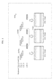
- the multiple-frame transmitting method is a method for transmitting the data with a frame configuration of the multiple frame transmission illustrated in FIG. 440 or FIG. 465 .
- One of the single-frame transmitting method and the multiple-frame transmitting method is determined.
- PTYPE illustrated in FIG. 465 is generated as the partition type information
- the combination data is generated by adding the partition type information to the data to be transmitted that is BODY.
- the visible light signal constructed with the plurality of frames each of which includes the preamble (PRE) is generated by dividing the combination data.
- the data to be transmitted is transmitted as the visible light signal constructed with the plurality of frames, so that long-distance communication is conducted, and a reception error and a reception delay can be reduced.
- the transmission method can properly be selected according to a communication distance or an amount of data to be transmitted. For example, when the reception delay occurs by dividing the small amount of data to be transmitted, the reception delay can be prevented by selecting the single-frame transmitting method.
- the partition type information is added to the data to be transmitted, so that the receiver can properly receive the data to be transmitted based on the partition type information. Accordingly, the communication can be conducted between various devices.
- the frame is a data unit, and is also referred to as a packet or a block.
- a first preamble may be added to the head of the frame located at a last position in an array of the plurality of frames as the preamble, and a second preamble different from the first preamble may be added to the head of the frame located at a position that is not the last position in the array as the preamble.
- the second preamble may be added to the head of each of the plurality of frames located at the positions that are not the last position.
- the first preamble (a last address of PRE) is added to the head of the frame located at the last position
- the second preamble (a not-last address of PRE) is added to the head of the frame located at the position that is not the last position. Therefore, the receiver that receives the visible light signal can easily find a break or boundary between the data to be transmitted and the next data to be transmitted, and the receiver can receive the plurality of pieces of data to be transmitted while properly distinguishing the plurality of pieces of data to be transmitted from each other.
- Each of the first and second preambles may be constructed with an N-bit (N is an integer of 2 or more) bit string, and the bit string may indicate a number previously correlated with a bit length of the data part included in each of the plurality of frames.
- each of the first and second preambles is a 12-bit bit string.
- the bit string indicates a number (for example, “1101 0000 0000” or “0000 0000 1101”) previously correlated with the bit length (for example, 64 bits) of the data part (DATAPART). Therefore, because the first and second preambles indicate the bit length of the data part while indicating the head of the frame, data that is used only to notify the receiver of the bit length of the data part needs not to be provided in the frame. Accordingly, time necessary for the transmission of the data to be transmitted can be shortened.
- the receiver can identify the bit length of the data part subsequent to the preambles. Resultantly, the receiver can properly receive the data part.
- M is an integer that is greater than or equal to 2 and less than N
- each of the first and second preambles correlated with a 64-bit data part is constructed with a 4-bit first bit string indicating “1101” and an 8-bit second bit string indicating “0000 0000”.
- the second bit string “0000 0000” is disposed next to the first bit string “1101”.
- the first bit string “1101” is disposed next to the second bit string “0000 0000”.
- the first preamble differs from the second preamble in the order in which the first bit string “1101” and the second bit string “0000 0000” are disposed.
- the first and second preambles are constructed as the bit strings different from each other, and include the partially common bit string. Therefore, the receiver can search the first and second preambles using the partially common bit string without distinguishing the first and second preambles from each other, and can search only the first preamble or the second preamble using the whole bit string of the preamble. Accordingly, data search efficiency can be improved.
- the partition type information may indicate, as the type of the data to be transmitted, a first type or a second type in which a restriction of a data configuration is stricter than that of the first type, and when the partition type information indicating the second type is added in the first addition step, length information indicating the bit length of the data to be transmitted, and ID type information indicating a type of identification information expressed by the data to be transmitted may further be added to the data to be transmitted.
- PTYPE that is the partition type information indicates the first type that is a data stream or the second type that is a single frame compatible.
- IDLEN and IDTYPE are added to the data to be transmitted (ID) as illustrated in (a) of FIG. 467 .
- IDLEN is length information indicating the bit length of the data to be transmitted
- IDTYPE indicates a type of ID (identification information) expressed by the data to be transmitted.
- a data format can be commonalized. That is, the receiver can properly receive the data to be transmitted irrespective of whether the data to be transmitted is transmitted by either the single-frame transmitting method or the multiple-frame transmitting method.
- FIG. 1 illustrates an example of imaging where imaging elements arranged in a line are exposed simultaneously, with the exposure start time being shifted in order of lines.
- the simultaneously exposed imaging elements are referred to as “exposure line”, and the line of pixels in the image corresponding to the imaging elements is referred to as “bright line”.
- the luminance change of the light source at a speed higher than the imaging frame rate can be estimated.
- transmitting a signal as the luminance change of the light source enables communication at a speed not less than the imaging frame rate.
- the lower luminance value is referred to as “low” (LO)
- the higher luminance value is referred to as “high” (HI).
- the low may be a state in which the light source emits no light, or a state in which the light source emits weaker light than in the high.
- the exposure time is set to less than 10 milliseconds, for example.
- FIG. 2 illustrates a situation where, after the exposure of one exposure line ends, the exposure of the next exposure line starts.
- the transmission speed is flm bits per second at the maximum, where m is the number of pixels per exposure line.
- each exposure line caused by the light emission of the light emitting unit is recognizable in a plurality of levels as illustrated in FIG. 3 , more information can be transmitted by controlling the light emission time of the light emitting unit in a shorter unit of time than the exposure time of each exposure line.
- information can be transmitted at a speed of flElv bits per second at the maximum.
- a fundamental period of transmission can be recognized by causing the light emitting unit to emit light with a timing slightly different from the timing of exposure of each exposure line.
- FIG. 4 illustrates a situation where, before the exposure of one exposure line ends, the exposure of the next exposure line starts. That is, the exposure times of adjacent exposure lines partially overlap each other.
- This structure has the feature (1): the number of samples in a predetermined time can be increased as compared with the case where, after the exposure of one exposure line ends, the exposure of the next exposure line starts. The increase of the number of samples in the predetermined time leads to more appropriate detection of the light signal emitted from the light transmitter which is the subject. In other words, the error rate when detecting the light signal can be reduced.
- the structure also has the feature (2): the exposure time of each exposure line can be increased as compared with the case where, after the exposure of one exposure line ends, the exposure of the next exposure line starts.
- the structure in which the exposure times of adjacent exposure lines partially overlap each other does not need to be applied to all exposure lines, and part of the exposure lines may not have the structure of partially overlapping in exposure time.
- the occurrence of an intermediate color caused by exposure time overlap is suppressed on the imaging screen, as a result of which bright lines can be detected more appropriately.
- the exposure time is calculated from the brightness of each exposure line, to recognize the light emission state of the light emitting unit.
- the light emitting unit in the case of determining the brightness of each exposure line in a binary fashion of whether or not the luminance is greater than or equal to a threshold, it is necessary for the light emitting unit to continue the state of emitting no light for at least the exposure time of each line, to enable the no light emission state to be recognized.
- FIG. 5A illustrates the influence of the difference in exposure time in the case where the exposure start time of each exposure line is the same.
- the exposure end time of one exposure line and the exposure start time of the next exposure line are the same.
- the exposure time is longer than that in 7500 a .
- the structure in which the exposure times of adjacent exposure lines partially overlap each other as in 7500 b allows a longer exposure time to be used. That is, more light enters the imaging element, so that a brighter image can be obtained.
- the imaging sensitivity for capturing an image of the same brightness can be reduced, an image with less noise can be obtained. Communication errors are prevented in this way.
- FIG. 5B illustrates the influence of the difference in exposure start time of each exposure line in the case where the exposure time is the same.
- the exposure end time of one exposure line and the exposure start time of the next exposure line are the same.
- the exposure of one exposure line ends after the exposure of the next exposure line starts.
- the structure in which the exposure times of adjacent exposure lines partially overlap each other as in 7501 b allows more lines to be exposed per unit time. This increases the resolution, so that more information can be obtained. Since the sample interval (i.e. the difference in exposure start time) is shorter, the luminance change of the light source can be estimated more accurately, contributing to a lower error rate. Moreover, the luminance change of the light source in a shorter time can be recognized. By exposure time overlap, light source blinking shorter than the exposure time can be recognized using the difference of the amount of exposure between adjacent exposure lines.
- the communication speed can be dramatically improved by using, for signal transmission, the bright line pattern generated by setting the exposure time shorter than in the normal imaging mode.
- Setting the exposure time in visible light communication to less than or equal to 1/480 second enables an appropriate bright line pattern to be generated.
- FIG. 5C illustrates the advantage of using a short exposure time in the case where each exposure line does not overlap in exposure time.
- the exposure time is long, even when the light source changes in luminance in a binary fashion as in 7502 a , an intermediate-color part tends to appear in the captured image as in 7502 e , making it difficult to recognize the luminance change of the light source.
- predetermined non-exposure blank time (predetermined wait time) t D2 from when the exposure of one exposure line ends to when the exposure of the next exposure line starts as in 7502 d , however, the luminance change of the light source can be recognized more easily. That is, a more appropriate bright line pattern can be detected as in 7502 f .
- the provision of the predetermined non-exposure blank time is possible by setting a shorter exposure time t E than the time difference t D between the exposure start times of the exposure lines, as in 7502 d .
- the exposure time is shortened from the normal imaging mode so as to provide the predetermined non-exposure blank time.
- the exposure end time of one exposure line and the exposure start time of the next exposure line are the same in the normal imaging mode, too, the exposure time is shortened so as to provide the predetermined non-exposure time.
- the predetermined non-exposure blank time (predetermined wait time) t D2 from when the exposure of one exposure line ends to when the exposure of the next exposure line starts may be provided by increasing the interval t D between the exposure start times of the exposure lines, as in 7502 g .
- This structure allows a longer exposure time to be used, so that a brighter image can be captured. Moreover, a reduction in noise contributes to higher error tolerance. Meanwhile, this structure is disadvantageous in that the number of samples is small as in 7502 h , because fewer exposure lines can be exposed in a predetermined time. Accordingly, it is desirable to use these structures depending on circumstances. For example, the estimation error of the luminance change of the light source can be reduced by using the former structure in the case where the imaging object is bright and using the latter structure in the case where the imaging object is dark.
- the structure in which the exposure times of adjacent exposure lines partially overlap each other does not need to be applied to all exposure lines, and part of the exposure lines may not have the structure of partially overlapping in exposure time.
- the structure in which the predetermined non-exposure blank time (predetermined wait time) is provided from when the exposure of one exposure line ends to when the exposure of the next exposure line starts does not need to be applied to all exposure lines, and part of the exposure lines may have the structure of partially overlapping in exposure time. This makes it possible to take advantage of each of the structures.
- the same reading method or circuit may be used to read a signal in the normal imaging mode in which imaging is performed at the normal frame rate (30 fps, 60 fps) and the visible light communication mode in which imaging is performed with the exposure time less than or equal to 1/480 second for visible light communication.
- the use of the same reading method or circuit to read a signal eliminates the need to employ separate circuits for the normal imaging mode and the visible light communication mode. The circuit size can be reduced in this way.
- FIG. 5D illustrates the relation between the minimum change time t S of light source luminance, the exposure time t E , the time difference t D between the exposure start times of the exposure lines, and the captured image.
- t E +t D ⁇ t S imaging is always performed in a state where the light source does not change from the start to end of the exposure of at least one exposure line.
- an image with clear luminance is obtained as in 7503 d , from which the luminance change of the light source is easily recognizable.
- 2t E >t S a bright line pattern different from the luminance change of the light source might be obtained, making it difficult to recognize the luminance change of the light source from the captured image.
- FIG. 5E illustrates the relation between the transition time t T of light source luminance and the time difference t D between the exposure start times of the exposure lines.
- t D is large as compared with t T , fewer exposure lines are in the intermediate color, which facilitates estimation of light source luminance. It is desirable that t D >t T , because the number of exposure lines in the intermediate color is two or less consecutively. Since t T is less than or equal to 1 microsecond in the case where the light source is an LED and about 5 microseconds in the case where the light source is an organic EL device, setting t D to greater than or equal to 5 microseconds facilitates estimation of light source luminance.
- FIG. 5F illustrates the relation between the high frequency noise t HT of light source luminance and the exposure time t E .
- t E When t E is large as compared with t HT , the captured image is less influenced by high frequency noise, which facilitates estimation of light source luminance.
- t E When t E is an integral multiple of t HT , there is no influence of high frequency noise, and estimation of light source luminance is easiest. For estimation of light source luminance, it is desirable that t E >t HT .
- High frequency noise is mainly caused by a switching power supply circuit. Since t HT is less than or equal to 20 microseconds in many switching power supplies for lightings, setting t E to greater than or equal to 20 microseconds facilitates estimation of light source luminance.
- FIG. 5G is a graph representing the relation between the exposure time t E and the magnitude of high frequency noise when t HT is 20 microseconds. Given that t HT varies depending on the light source, the graph demonstrates that it is efficient to set t E to greater than or equal to 15 microseconds, greater than or equal to 35 microseconds, greater than or equal to 54 microseconds, or greater than or equal to 74 microseconds, each of which is a value equal to the value when the amount of noise is at the maximum.
- t E is desirably larger in terms of high frequency noise reduction, there is also the above-mentioned property that, when t E is smaller, an intermediate-color part is less likely to occur and estimation of light source luminance is easier.
- t E may be set to greater than or equal to 15 microseconds when the light source luminance change period is 15 to 35 microseconds, to greater than or equal to 35 microseconds when the light source luminance change period is 35 to 54 microseconds, to greater than or equal to 54 microseconds when the light source luminance change period is 54 to 74 microseconds, and to greater than or equal to 74 microseconds when the light source luminance change period is greater than or equal to 74 microseconds.
- FIG. 5H illustrates the relation between the exposure time t E and the recognition success rate. Since the exposure time t E is relative to the time during which the light source luminance is constant, the horizontal axis represents the value (relative exposure time) obtained by dividing the light source luminance change period t S by the exposure time t E . It can be understood from the graph that the recognition success rate of approximately 100% can be attained by setting the relative exposure time to less than or equal to 1.2. For example, the exposure time may be set to less than or equal to approximately 0.83 millisecond in the case where the transmission signal is 1 kHz.
- the recognition success rate greater than or equal to 95% can be attained by setting the relative exposure time to less than or equal to 1.25
- the recognition success rate greater than or equal to 80% can be attained by setting the relative exposure time to less than or equal to 1.4.
- the recognition success rate sharply decreases when the relative exposure time is about 1.5 and becomes roughly 0% when the relative exposure time is 1.6, it is necessary to set the relative exposure time not to exceed 1.5. After the recognition rate becomes 0% at 7507 c , it increases again at 7507 d , 7507 e , and 7507 f .
- the exposure time may be set so that the relative exposure time is 1.9 to 2.2, 2.4 to 2.6, or 2.8 to 3.0.
- Such an exposure time may be used, for instance, as an intermediate mode in FIG. 7 .
- FIG. 6A is a flowchart of an information communication method in this embodiment.
- the information communication method in this embodiment is an information communication method of obtaining information from a subject, and includes Steps SK 91 to SK 93 .
- the information communication method includes: a first exposure time setting step SK 91 of setting a first exposure time of an image sensor so that, in an image obtained by capturing the subject by the image sensor, a plurality of bright lines corresponding to a plurality of exposure lines included in the image sensor appear according to a change in luminance of the subject; a first image obtainment step SK 92 of obtaining a bright line image including the plurality of bright lines, by capturing the subject changing in luminance by the image sensor with the set first exposure time; and an information obtainment step SK 93 of obtaining the information by demodulating data specified by a pattern of the plurality of bright lines included in the obtained bright line image, wherein in the first image obtainment step SK 92 , exposure starts sequentially for the plurality of exposure lines each at a different time, and exposure of each of the plurality of exposure lines starts after a predetermined blank time elapses from when exposure of an adjacent exposure line adjacent to the exposure line ends.
- FIG. 6B is a block diagram of an information communication device in this embodiment.
- An information communication device K 90 in this embodiment is an information communication device that obtains information from a subject, and includes structural elements K 91 to K 93 .
- the information communication device K 90 includes: an exposure time setting unit K 91 that sets an exposure time of an image sensor so that, in an image obtained by capturing the subject by the image sensor, a plurality of bright lines corresponding to a plurality of exposure lines included in the image sensor appear according to a change in luminance of the subject; an image obtainment unit K 92 that includes the image sensor, and obtains a bright line image including the plurality of bright lines by capturing the subject changing in luminance with the set exposure time; and an information obtainment unit K 93 that obtains the information by demodulating data specified by a pattern of the plurality of bright lines included in the obtained bright line image, wherein exposure starts sequentially for the plurality of exposure lines each at a different time, and exposure of each of the plurality of exposure lines starts after a predetermined blank time elapses from when exposure of an adjacent exposure line adjacent to the exposure line ends.
- the exposure of each of the plurality of exposure lines starts a predetermined blank time after the exposure of the adjacent exposure line adjacent to the exposure line ends, for instance as illustrated in FIG. 5C .
- each of the constituent elements may be constituted by dedicated hardware, or may be obtained by executing a software program suitable for the constituent element.
- Each constituent element may be achieved by a program execution unit such as a CPU or a processor reading and executing a software program stored in a recording medium such as a hard disk or semiconductor memory.
- the program causes a computer to execute the information communication method illustrated in the flowchart of FIG. 6A .
- This embodiment describes each example of application using a receiver such as a smartphone which is the information communication device K 90 and a transmitter for transmitting information as a blink pattern of the light source such as an LED or an organic EL device in Embodiment 1 described above.
- FIG. 7 is a diagram illustrating an example of each mode of a receiver in this embodiment.
- a receiver 8000 performs imaging at a shutter speed of 1/100 second as an example to obtain a normal captured image, and displays the normal captured image on a display.
- a subject such as a street lighting or a signage as a store sign and its surroundings are clearly shown in the normal captured image.
- the receiver 8000 performs imaging at a shutter speed of 1/10000 second as an example, to obtain a visible light communication image.
- a visible light communication image For example, in the case where the above-mentioned street lighting or signage is transmitting a signal by way of luminance change as the light source described in Embodiment 1, that is, a transmitter, one or more bright lines (hereafter referred to as “bright line pattern”) are shown in the signal transmission part of the visible light communication image, while nothing is shown in the other part. That is, in the visible light communication image, only the bright line pattern is shown and the part of the subject not changing in luminance and the surroundings of the subject are not shown.
- the receiver 8000 performs imaging at a shutter speed of 1/3000 second as an example, to obtain an intermediate image.
- the bright line pattern is shown, and the part of the subject not changing in luminance and the surroundings of the subject are shown, too.
- the receiver 8000 displaying the intermediate image on the display, the user can find out from where or from which position the signal is being transmitted.
- the bright line pattern, the subject, and its surroundings shown in the intermediate image are not as clear as the bright line pattern in the visible light communication image and the subject and its surroundings in the normal captured image respectively, but have the level of clarity recognizable by the user.
- the normal imaging mode or imaging in the normal imaging mode is referred to as “normal imaging”
- the visible light communication mode or imaging in the visible light communication mode is referred to as “visible light imaging” (visible light communication).
- Imaging in the intermediate mode may be used instead of normal imaging and visible light imaging, and the intermediate image may be used instead of the below-mentioned synthetic image.
- FIG. 8 is a diagram illustrating an example of imaging operation of a receiver in this embodiment.
- the receiver 8000 switches the imaging mode in such a manner as normal imaging, visible light communication, normal imaging, . . . .
- the receiver 8000 synthesizes the normal captured image and the visible light communication image to generate a synthetic image in which the bright line pattern, the subject, and its surroundings are clearly shown, and displays the synthetic image on the display.
- the synthetic image is an image generated by superimposing the bright line pattern of the visible light communication image on the signal transmission part of the normal captured image.
- the bright line pattern, the subject, and its surroundings shown in the synthetic image are clear, and have the level of clarity sufficiently recognizable by the user. Displaying such a synthetic image enables the user to more distinctly find out from which position the signal is being transmitted.
- FIG. 9 is a diagram illustrating another example of imaging operation of a receiver in this embodiment.
- the receiver 8000 includes a camera Ca 1 and a camera Ca 2 .
- the camera Ca 1 performs normal imaging
- the camera Ca 2 performs visible light imaging.
- the camera Ca 1 obtains the above-mentioned normal captured image
- the camera Ca 2 obtains the above-mentioned visible light communication image.
- the receiver 8000 synthesizes the normal captured image and the visible light communication image to generate the above-mentioned synthetic image, and displays the synthetic image on the display.
- FIG. 10A is a diagram illustrating another example of imaging operation of a receiver in this embodiment.
- the camera Ca 1 switches the imaging mode in such a manner as normal imaging, visible light communication, normal imaging, . . . . Meanwhile, the camera Ca 2 continuously performs normal imaging.
- the receiver 8000 estimates the distance (hereafter referred to as “subject distance”) from the receiver 8000 to the subject based on the normal captured images obtained by these cameras, through the use of stereoscopy (triangulation principle). By using such estimated subject distance, the receiver 8000 can superimpose the bright line pattern of the visible light communication image on the normal captured image at the appropriate position. The appropriate synthetic image can be generated in this way.
- FIG. 10B is a diagram illustrating another example of imaging operation of a receiver in this embodiment.
- the receiver 8000 includes three cameras (cameras Ca 1 , Ca 2 , and Ca 3 ) as an example.
- two cameras (cameras Ca 2 and Ca 3 ) continuously perform normal imaging, and the remaining camera (camera Ca 1 ) continuously performs visible light communication.
- the subject distance can be estimated at any timing, based on the normal captured images obtained by two cameras engaged in normal imaging.
- FIG. 10C is a diagram illustrating another example of imaging operation of a receiver in this embodiment.
- the receiver 8000 includes three cameras (cameras Ca 1 , Ca 2 , and Ca 3 ) as an example.
- each camera switches the imaging mode in such a manner as normal imaging, visible light communication, normal imaging, . . . .
- the imaging mode of each camera is switched per period so that, in one period, two cameras perform normal imaging and the remaining camera performs visible light communication. That is, the combination of cameras engaged in normal imaging is changed periodically.
- the subject distance can be estimated in any period, based on the normal captured images obtained by two cameras engaged in normal imaging.
- FIG. 11A is a diagram illustrating an example of camera arrangement of a receiver in this embodiment.
- the receiver 8000 includes two cameras Ca 1 and Ca 2
- the two cameras Ca 1 and Ca 2 are positioned away from each other as illustrated in FIG. 11A .
- the subject distance can be accurately estimated in this way. In other words, the subject distance can be estimated more accurately when the distance between two cameras is longer.
- FIG. 11B is a diagram illustrating another example of camera arrangement of a receiver in this embodiment.
- the receiver 8000 includes three cameras Ca 1 , Ca 2 , and Ca 3
- the two cameras Ca 1 and Ca 2 for normal imaging are positioned away from each other as illustrated in FIG. 11B
- the camera Ca 3 for visible light communication is, for example, positioned between the cameras Ca 1 and Ca 2 .
- the subject distance can be accurately estimated in this way. In other words, the subject distance can be accurately estimated by using two farthest cameras for normal imaging.
- FIG. 12 is a diagram illustrating an example of display operation of a receiver in this embodiment.
- the receiver 8000 switches the imaging mode in such a manner as visible light communication, normal imaging, visible light communication, . . . , as mentioned above.
- the receiver 8000 starts an application program.
- the receiver 8000 estimates its position based on the signal received by visible light communication.
- the receiver 8000 displays AR (Augmented Reality) information on the normal captured image obtained by normal imaging.
- the AR information is obtained based on, for example, the position estimated as mentioned above.
- the receiver 8000 also estimates the change in movement and direction of the receiver 8000 based on the detection result of the 9-axis sensor, the motion detection in the normal captured image, and the like, and moves the display position of the AR information according to the estimated change in movement and direction. This enables the AR information to follow the subject image in the normal captured image.
- the receiver 8000 When switching the imaging mode from normal imaging to visible light communication, in visible light communication the receiver 8000 superimposes the AR information on the latest normal captured image obtained in immediately previous normal imaging. The receiver 8000 then displays the normal captured image on which the AR information is superimposed. The receiver 8000 also estimates the change in movement and direction of the receiver 8000 based on the detection result of the 9-axis sensor, and moves the AR information and the normal captured image according to the estimated change in movement and direction, in the same way as in normal imaging. This enables the AR information to follow the subject image in the normal captured image according to the movement of the receiver 8000 and the like in visible light communication, as in normal imaging. Moreover, the normal image can be enlarged or reduced according to the movement of the receiver 8000 and the like.
- FIG. 13 is a diagram illustrating an example of display operation of a receiver in this embodiment.
- the receiver 8000 may display the synthetic image in which the bright line pattern is shown, as illustrated in (a) in FIG. 13 .
- the receiver 8000 may superimpose, instead of the bright line pattern, a signal specification object which is an image having a predetermined color for notifying signal transmission on the normal captured image to generate the synthetic image, and display the synthetic image, as illustrated in (b) in FIG. 13 .
- the receiver 8000 may display, as the synthetic image, the normal captured image in which the signal transmission part is indicated by a dotted frame and an identifier (e.g. ID: 101 , ID: 102 , etc.), as illustrated in (c) in FIG. 13 .
- the receiver 8000 may superimpose, instead of the bright line pattern, a signal identification object which is an image having a predetermined color for notifying transmission of a specific type of signal on the normal captured image to generate the synthetic image, and display the synthetic image, as illustrated in (d) in FIG. 13 .
- the color of the signal identification object differs depending on the type of signal output from the transmitter. For example, a red signal identification object is superimposed in the case where the signal output from the transmitter is position information, and a green signal identification object is superimposed in the case where the signal output from the transmitter is a coupon.
- FIG. 14 is a diagram illustrating an example of display operation of a receiver in this embodiment.
- the receiver 8000 may output a sound for notifying the user that the transmitter has been discovered, while displaying the normal captured image.
- the receiver 8000 may change the type of output sound, the number of outputs, or the output time depending on the number of discovered transmitters, the type of received signal, the type of information specified by the signal, or the like.
- FIG. 15 is a diagram illustrating another example of operation of a receiver in this embodiment.
- the receiver 8000 when the user touches the bright line pattern shown in the synthetic image, the receiver 8000 generates an information notification image based on the signal transmitted from the subject corresponding to the touched bright line pattern, and displays the information notification image.
- the information notification image indicates, for example, a coupon or a location of a store.
- the bright line pattern may be the signal specification object, the signal identification object, or the dotted frame illustrated in FIG. 13 . The same applies to the below-mentioned bright line pattern.
- FIG. 16 is a diagram illustrating another example of operation of a receiver in this embodiment.
- the receiver 8000 when the user touches the bright line pattern shown in the synthetic image, the receiver 8000 generates an information notification image based on the signal transmitted from the subject corresponding to the touched bright line pattern, and displays the information notification image.
- the information notification image indicates, for example, the current position of the receiver 8000 by a map or the like.
- FIG. 17 is a diagram illustrating another example of operation of a receiver in this embodiment.
- the receiver 8000 receives signals from two street lightings which are subjects as transmitters.
- the receiver 8000 estimates the current position of the receiver 8000 based on these signals, in the same way as above.
- the receiver 8000 displays the normal captured image, and also superimposes an information notification image (an image showing latitude, longitude, and the like) indicating the estimation result on the normal captured image.
- the receiver 8000 may also display an auxiliary information notification image on the normal captured image.
- the auxiliary information notification image prompts the user to perform an operation for calibrating the 9-axis sensor (particularly the geomagnetic sensor), i.e. an operation for drift cancellation. As a result of such an operation, the current position can be estimated with high accuracy.
- the receiver 8000 may display the map showing the estimated position, instead of the normal captured image.
- FIG. 18 is a diagram illustrating another example of operation of a receiver in this embodiment.
- the receiver 8000 displays the normal captured image including the dotted frame and the identifier like the normal captured image illustrated in (c) in FIG. 13 , and also displays a list of information to follow the swipe operation.
- the list includes information specified by the signal transmitted from the part (transmitter) identified by each identifier.
- the swipe may be, for example, an operation of moving the user's finger from outside the display of the receiver 8000 on the right side into the display.
- the swipe may be an operation of moving the user's finger from the top, bottom, or left side of the display into the display.
- the receiver 8000 may display an information notification image (e.g. an image showing a coupon) indicating the information in more detail.
- an information notification image e.g. an image showing a coupon
- FIG. 19 is a diagram illustrating another example of operation of a receiver in this embodiment.
- the receiver 8000 when the user swipes on the receiver 8000 on which the synthetic image is displayed, the receiver 8000 superimposes an information notification image on the synthetic image, to follow the swipe operation.
- the information notification image indicates the subject distance with an arrow so as to be easily recognizable by the user.
- the swipe may be, for example, an operation of moving the user's finger from outside the display of the receiver 8000 on the bottom side into the display.
- the swipe may be an operation of moving the user's finger from the left, top, or right side of the display into the display.
- FIG. 20 is a diagram illustrating another example of operation of a receiver in this embodiment.
- the receiver 8000 captures, as a subject, a transmitter which is a signage showing a plurality of stores, and displays the normal captured image obtained as a result.
- the receiver 8000 When the user taps a signage image of one store included in the subject shown in the normal captured image, the receiver 8000 generates an information notification image based on the signal transmitted from the signage of the store, and displays an information notification image 8001 .
- the information notification image 8001 is, for example, an image showing the availability of the store and the like.
- FIG. 21 is a diagram illustrating an example of operation of a receiver, a transmitter, and a server in this embodiment.
- a transmitter 8012 as a television transmits a signal to a receiver 8011 by way of luminance change.
- the signal includes information prompting the user to buy content relating to a program being viewed. Having received the signal by visible light communication, the receiver 8011 displays an information notification image prompting the user to buy content, based on the signal.
- the receiver 8011 transmits at least one of information included in a SIM (Subscriber Identity Module) card inserted in the receiver 8011 , a user ID, a terminal ID, credit card information, charging information, a password, and a transmitter ID, to a server 8013 .
- the server 8013 manages a user ID and payment information in association with each other, for each user.
- the server 8013 specifies a user ID based on the information transmitted from the receiver 8011 , and checks payment information associated with the user ID. By this check, the server 8013 determines whether or not to permit the user to buy the content. In the case of determining to permit the user to buy the content, the server 8013 transmits permission information to the receiver 8011 . Having received the permission information, the receiver 8011 transmits the permission information to the transmitter 8012 . Having received the permission information, the transmitter 8012 obtains the content via a network as an example, and reproduces the content.
- the transmitter 8012 may transmit information including the ID of the transmitter 8012 to the receiver 8011 , by way of luminance change.
- the receiver 8011 transmits the information to the server 8013 .
- the server 8013 can determine that, for example, the television program is being viewed on the transmitter 8012 , and conduct television program rating research.
- the receiver 8011 may include information of an operation (e.g. voting) performed by the user in the above-mentioned information and transmit the information to the server 8013 , to allow the server 8013 to reflect the information on the television program.
- An audience participation program can be realized in this way.
- the receiver 8011 may include the post in the above-mentioned information and transmit the information to the server 8013 , to allow the server 8013 to reflect the post on the television program, a network message board, or the like.
- the server 8013 can charge for television program viewing by paid broadcasting or on-demand TV.
- the server 8013 can also cause the receiver 8011 to display an advertisement, or the transmitter 8012 to display detailed information of the displayed television program or an URL of a site showing the detailed information.
- the server 8013 may also obtain the number of times the advertisement is displayed on the receiver 8011 , the price of a product bought from the advertisement, or the like, and charge the advertiser according to the number of times or the price. Such price-based charging is possible even in the case where the user seeing the advertisement does not buy the product immediately.
- the server 8013 may provide a service (e.g. payment for selling the product) to the manufacturer indicated by the information.
- FIG. 22 is a diagram illustrating another example of operation of a receiver in this embodiment.
- the user points a camera of a receiver 8021 at a plurality of transmitters 8020 a to 8020 d as lightings.
- the receiver 8021 is moved so that the transmitters 8020 a to 8020 d are sequentially captured as a subject.
- the receiver 8021 receives a signal from each of the transmitters 8020 a to 8020 d .
- the signal includes information indicating the position of the transmitter.
- the receiver 8021 estimates the position of the receiver 8021 using the triangulation principle, based on the positions indicated by the signals received from the transmitters 8020 a to 8020 d , the detection result of the 9-axis sensor included in the receiver 8021 , and the movement of the captured image. In this case, the drift of the 9-axis sensor (particularly the geomagnetic sensor) is canceled by moving the receiver 8021 , so that the position can be estimated with higher accuracy.
- FIG. 23 is a diagram illustrating another example of operation of a receiver in this embodiment.
- a receiver 8030 is a head-mounted display including a camera.
- the receiver 8030 starts imaging in the visible light communication mode, i.e. visible light communication.
- the receiver 8030 notifies the user of information corresponding to the received signal. The notification is made, for example, by outputting a sound from a speaker included in the receiver 8030 , or by displaying an image.
- Visible light communication may be started not only when the start button is pressed, but also when the receiver 8030 receives a sound instructing the start or when the receiver 8030 receives a signal instructing the start by wireless communication.
- Visible light communication may also be started when the change width of the value obtained by a 9-axis sensor included in the receiver 8030 exceeds a predetermined range or when a bright line pattern, even if only slightly, appears in the normal captured image.
- FIG. 24 is a diagram illustrating an example of initial setting of a receiver in this embodiment.
- the receiver 8030 displays an alignment image 8031 upon initial setting.
- the alignment image 8031 is used to align the position pointed by the user in the image captured by the camera of the receiver 8030 and the image displayed on the receiver 8030 .
- the receiver 8030 associates the position of the fingertip and the position of the circle, and performs alignment. That is, the position pointed by the user is calibrated.
- FIG. 25 is a diagram illustrating another example of operation of a receiver in this embodiment.
- the receiver 8030 specifies a signal transmission part by visible light communication, and displays a synthetic image 8034 in which a bright line pattern is shown in the part.
- the user performs an operation such as a tap or a double tap, on the bright line pattern.
- the receiver 8030 receives the operation, specifies the bright line pattern subjected to the operation, and displays an information notification image 8032 based on a signal transmitted from the part corresponding to the bright line pattern.
- FIG. 26 is a diagram illustrating another example of operation of a receiver in this embodiment.
- the receiver 8030 displays the synthetic image 8034 in the same way as above.
- the user performs an operation of moving his or her fingertip so as to encircle the bright line pattern in the synthetic image 8034 .
- the receiver 8030 receives the operation, specifies the bright line pattern subjected to the operation, and displays an information notification image 8032 based on a signal transmitted from the part corresponding to the bright line pattern.
- FIG. 27 is a diagram illustrating another example of operation of a receiver in this embodiment.
- the receiver 8030 displays the synthetic image 8034 in the same way as above.
- the user performs an operation of placing his or her fingertip at the bright line pattern in the synthetic image 8034 for a predetermined time or more.
- the receiver 8030 receives the operation, specifies the bright line pattern subjected to the operation, and displays an information notification image 8032 based on a signal transmitted from the part corresponding to the bright line pattern.
- FIG. 28 is a diagram illustrating another example of operation of a receiver in this embodiment.
- the receiver 8030 displays the synthetic image 8034 in the same way as above.
- the user performs an operation of moving his or her fingertip toward the bright line pattern in the synthetic image 8034 by a swipe.
- the receiver 8030 receives the operation, specifies the bright line pattern subjected to the operation, and displays an information notification image 8032 based on a signal transmitted from the part corresponding to the bright line pattern.
- FIG. 29 is a diagram illustrating another example of operation of a receiver in this embodiment.
- the receiver 8030 displays the synthetic image 8034 in the same way as above.
- the user performs an operation of continuously directing his or her gaze to the bright line pattern in the synthetic image 8034 for a predetermined time or more.
- the user performs an operation of blinking a predetermined number of times while directing his or her gaze to the bright line pattern.
- the receiver 8030 receives the operation, specifies the bright line pattern subjected to the operation, and displays an information notification image 8032 based on a signal transmitted from the part corresponding to the bright line pattern.
- FIG. 30 is a diagram illustrating another example of operation of a receiver in this embodiment.
- the receiver 8030 displays the synthetic image 8034 in the same way as above, and also displays an arrow associated with each bright line pattern in the synthetic image 8034 .
- the arrow of each bright line pattern differs in direction.
- the user performs an operation of moving his or her head along one of the arrows.
- the receiver 8030 receives the operation based on the detection result of the 9-axis sensor, and specifies the bright line pattern associated with the arrow corresponding to the operation, i.e. the arrow in the direction in which the head is moved.
- the receiver 8030 displays the information notification image 8032 based on the signal transmitted from the part corresponding to the bright line pattern.
- FIG. 31A is a diagram illustrating a pen used to operate a receiver in this embodiment.
- a pen 8033 includes a transmitter 8033 a for transmitting a signal by way of luminance change, and buttons 8033 b and 8033 c .
- the transmitter 8033 a transmits a predetermined first signal.
- the transmitter 8033 a transmits a predetermined second signal different from the first signal.
- FIG. 31B is a diagram illustrating operation of a receiver using a pen in this embodiment.
- the pen 8033 is used instead of the user's finger mentioned above, like a stylus pen.
- the pen 8033 can be used like a normal pen or an eraser.
- FIG. 32 is a diagram illustrating an example of appearance of a receiver in this embodiment.
- the receiver 8030 includes a first touch sensor 8030 a and a second touch sensor 8030 b . These touch sensors are attached to the frame of the receiver 8030 . For example, when the user places his or her fingertip on the first touch sensor 8030 a and moves the fingertip, the receiver 8030 moves the pointer in the image displayed to the user, according to the movement of the fingertip. When the user touches the second touch sensor 8030 b , the receiver 8030 selects the object pointed by the pointer in the image displayed to the user.
- FIG. 33 is a diagram illustrating another example of appearance of a receiver in this embodiment.
- the receiver 8030 includes a touch sensor 8030 c .
- the touch sensor 8030 c is attached to the frame of the receiver 8030 .
- the receiver 8030 moves the pointer in the image displayed to the user, according to the movement of the fingertip.
- the receiver 8030 selects the object pointed by the pointer in the image displayed to the user.
- the touch sensor 8030 c is thus realized as a clickable touch sensor.
- FIG. 34 is a diagram illustrating another example of operation of a receiver in this embodiment.
- the receiver 8030 displays the synthetic image 8034 in the same way as above, and also displays a pointer 8035 in the synthetic image 8034 .
- the receiver 8030 includes the first touch sensor 8030 a and the second touch sensor 8030 b
- the user places his or her fingertip on the first touch sensor 8030 a and moves the fingertip, to move the pointer to the object as the bright line pattern.
- the user touches the second touch sensor 8030 b , to cause the receiver 8030 to select the bright line pattern.
- the receiver 8030 displays the information notification image 8032 based on the signal transmitted from the part corresponding to the bright line pattern.
- the receiver 8030 includes the touch sensor 8030 c
- the user places his or her fingertip on the touch sensor 8030 c and moves the fingertip, to move the pointer to the object as the bright line pattern.
- the user then presses the touch sensor 8030 c , to cause the receiver 8030 to select the bright line pattern.
- the receiver 8030 displays the information notification image 8032 based on the signal transmitted from the part corresponding to the bright line pattern.
- FIG. 35A is a diagram illustrating another example of operation of a receiver in this embodiment.
- the receiver 8030 displays a gesture confirmation image 8036 based on a signal obtained by visible light communication.
- the gesture confirmation image 8036 prompts the user to make a predetermined gesture, to provide a service to the user as an example.
- FIG. 35B is a diagram illustrating an example of application using a receiver in this embodiment.
- a user 8038 carrying the receiver 8030 is in a shop or the like.
- the receiver 8030 displays the above-mentioned gesture confirmation image 8036 to the user 8038 .
- the user 8038 makes the predetermined gesture according to the gesture confirmation image 8036 .
- a staff 8039 in the shop carries a receiver 8037 .
- the receiver 8037 is a head-mounted display including a camera, and may have the same structure as the receiver 8030 .
- the receiver 8037 displays the gesture confirmation image 8036 based on a signal obtained by visible light communication, too.
- the staff 8039 determines whether or not the predetermined gesture indicated by the displayed gesture confirmation image 8036 and the gesture made by the user 8038 match. In the case of determining that the predetermined gesture and the gesture made by the user 8038 match, the staff 8039 provides the service associated with the gesture confirmation image 8036 , to the user 8038 .
- FIG. 36A is a diagram illustrating another example of operation of a receiver in this embodiment.
- the receiver 8030 displays a gesture confirmation image 8040 based on a signal obtained by visible light communication.
- the gesture confirmation image 8040 prompts the user to make a predetermined gesture, to permit wireless communication as an example.
- FIG. 36B is a diagram illustrating an example of application using a receiver in this embodiment.
- the user 8038 carries the receiver 8030 .
- the receiver 8030 displays the above-mentioned gesture confirmation image 8040 to the user 8038 .
- the user 8038 makes the predetermined gesture according to the gesture confirmation image 8040 .
- a person 8041 around the user 8038 carries the receiver 8037 .
- the receiver 8037 is a head-mounted display including a camera, and may have the same structure as the receiver 8030 .
- the receiver 8037 captures the predetermined gesture made by the user 8038 , to obtain authentication information such as a password included in the gesture. In the case where the receiver 8037 determines that the authentication information matches predetermined information, the receiver 8037 establishes wireless connection with the receiver 8030 . Subsequently, the receivers 8030 and 8037 can wirelessly communicate with each other.
- FIG. 37A is a diagram illustrating an example of operation of a transmitter in this embodiment.
- the transmitter alternately transmits signals 1 and 2, for example in a predetermined period.
- the transmission of the signal 1 and the transmission of the signal 2 are each carried out by way of luminance change such as blinking of visible light.
- a luminance change pattern for transmitting the signal 1 and a luminance change pattern for transmitting the signal 2 are different from each other.
- FIG. 37B is a diagram illustrating another example of operation of a transmitter in this embodiment.
- the transmitter may transmit the signals 1 and 2 intermittently with a buffer time, instead of continuously transmitting the signals 1 and 2 as mentioned above. In the buffer time, the transmitter does not change in luminance. Alternatively, in the buffer time, the transmitter may transmit a signal indicating that the transmitter is in the buffer time by way of luminance change, or perform a luminance change different from the luminance change for transmitting the signal 1 or the luminance change for transmitting the signal 2. This enables the receiver to appropriately receive the signals 1 and 2 without interference.
- FIG. 38 is a diagram illustrating another example of operation of a transmitter in this embodiment.
- the transmitter repeatedly transmits a signal sequence made up of a preamble, a block 1, a block 2, a block 3, and a check signal, by way of luminance change.
- the block 1 includes a preamble, an address 1, data 1, and a check signal.
- the blocks 2 and 3 each have the same structure as the block 1. Specific information is obtained by using data included in the blocks 1, 2, and 3.
- one set of data or information is stored in a state of being divided into three blocks. Accordingly, even when a receiver that needs a blanking interval for imaging cannot receive all data of the blocks 1, 2, and 3 from one signal sequence, the receiver can receive the remaining data from another signal sequence. As a result, even a receiver that needs a blanking interval can appropriately obtain the specific information from at least one signal sequence.
- a preamble and a check signal are provided for a set of three blocks.
- a receiver capable of receiving light without needing a blanking interval such as a receiver including an illuminance sensor, can receive one signal sequence at one time through the use of the preamble and the check signal provided for the set, thus obtaining the specific information in a short time.
- FIG. 39 is a diagram illustrating another example of operation of a transmitter in this embodiment.
- the transmitter may change, for each signal sequence, the order of the blocks included in the signal sequence. For example, the blocks 1, 2, and 3 are included in this order in the first signal sequence, and the blocks 3, 1, and 2 are included in this order in the next signal sequence.
- a receiver that requires a periodic blanking interval can therefore avoid obtaining only the same block.
- FIG. 40 is a diagram illustrating an example of communication form between a plurality of transmitters and a receiver in this embodiment.
- a receiver 8050 may receive signals (visible light) transmitted from transmitters 8051 a and 8051 b as lightings and reflected by a reflection surface.
- the receiver 8050 can thus receive signals from many transmitters all together.
- the transmitters 8051 a and 8051 b transmit signals of different frequencies or protocols.
- the receiver 8050 can receive the signals from the transmitters without interference.
- FIG. 41 is a diagram illustrating an example of operation of a plurality of transmitters in this embodiment.
- One of the transmitters 8051 a and 8051 b may monitor the signal transmission state of the other transmitter, and transmit a signal to avoid interference with a signal of the other transmitter. For instance, one transmitter receives a signal transmitted from the other transmitter, and transmits a signal of a protocol different from the received signal. Alternatively, one transmitter detects a time period during which no signal is transmitted from the other transmitter, and transmits a signal during the time period.
- FIG. 42 is a diagram illustrating another example of communication form between a plurality of transmitters and a receiver in this embodiment.
- the transmitters 8051 a and 8051 b may transmit signals of the same frequency or protocol.
- the receiver 8050 specifies the strength of the signal transmitted from each of the transmitters, i.e. the edge strength of the bright line included in the captured image. The strength is lower when the distance between the receiver 8050 and the transmitter is longer. In the case where the distance between the receiver 8050 and the transmitter 8051 a and the distance between the receiver 8050 and the transmitter 8051 b are different from each other, the difference in distance can be exploited in this way.
- the receiver 8050 can separately receive the signals transmitted from the transmitters 8051 a and 8051 b appropriately, according to the specified strengths.
- FIG. 43 is a diagram illustrating another example of operation of a receiver in this embodiment.
- the receiver 8050 receives a signal transmitted from the transmitter 8051 a and reflected by a reflection surface.
- the receiver 8050 may estimate the position of the transmitter 8051 a , based on the strength distribution of luminance (the difference in luminance between a plurality of positions) in the captured image.
- FIG. 44 is a diagram illustrating an example of application of a receiver in this embodiment.
- a receiver 7510 a such as a smartphone captures a light source 7510 b by a back camera (out camera) 7510 c to receive a signal transmitted from the light source 7510 b , and obtains the position and direction of the light source 7510 b from the received signal.
- the receiver 7510 a estimates the position and direction of the receiver 7510 a , from the state of the light source 7510 b in the captured image and the sensor value of the 9-axis sensor included in the receiver 7510 a .
- the receiver 7510 a captures a user 7510 e by a front camera (face camera, in camera) 7510 f , and estimates the position and direction of the head and the gaze direction (the position and direction of the eye) of the user 7510 e by image processing.
- the receiver 7510 a transmits the estimation result to the server.
- the receiver 7510 a changes the behavior (display content or playback sound) according to the gaze direction of the user 7510 e .
- the imaging by the back camera 7510 c and the imaging by the front camera 7510 f may be performed simultaneously or alternately.
- FIG. 45 is a diagram illustrating an example of application of a receiver in this embodiment.
- Receivers 7511 d and 7511 i such as smartphones respectively receive signals from light sources 7511 b and 7511 g , estimate the positions and directions of the receivers 7511 d and 7511 i , and estimate the gaze directions of users 7511 e and 7511 j , as in the above-mentioned way.
- the receivers 7511 d and 7511 i respectively obtain information of surrounding objects 7511 a to 7511 c and 7511 f to 7511 h from a server, based on the received data.
- the receivers 7511 d and 7511 i change their display contents as if the users can see the objects on the opposite side through the receivers 7511 d and 7511 i .
- the receivers 7511 d and 7511 i display an AR (Augmented Reality) object such as 7511 k , according to the display contents.
- the receiver 7511 i displays that the range is exceeded, as in 7511 l .
- the receiver 7511 i displays an AR object or other information in the area outside the range.
- the receiver 7511 i displays a previously captured image in the area outside the range in a state of being connected to the current image.
- FIG. 46 is a diagram illustrating an example of application of a receiver in this embodiment.
- a receiver 7512 c such as a smartphone receives a signal from a light source 7512 a , estimates the position and direction of the receiver 7512 c , and estimates the gaze direction of a user 7512 d , as in the above-mentioned way.
- the receiver 7512 c performs a process relating to an object 7512 b in the gaze direction of the user 7512 d .
- the receiver 7512 c displays information about the object 7512 b on the screen.
- the receiver 7512 g determines that the user 7512 h is interested in the object 7512 f , and continues the process relating to the object 7512 f . For example, the receiver 7512 g keeps displaying the information of the object 7512 f on the screen.
- FIG. 47 is a diagram illustrating an example of application of a transmitter in this embodiment.
- a transmitter 7513 a such as a lighting is high in luminance. Regardless of whether the luminance is high or low as a transmission signal, the transmitter 7513 a captured by a receiver exceeds an upper limit of brightness, and as a result no bright line appears as in 7513 b . Accordingly, a transmitter 7513 c includes a part 7513 d such as a diffusion plate or a prism for diffusing or weakening light, to reduce the luminance. As a result, the receiver can capture bright lines as in 7513 e.
- FIG. 48 is a diagram illustrating an example of application of a transmitter in this embodiment.
- a transmitter 7514 a such as a lighting does not have a uniform light source, and so the luminance is not uniform in a captured image 7514 b , causing a reception error.
- a transmitter 7514 c includes a part 7514 d such as a diffusion plate or a prism for diffusing light, to attain uniform luminance as in 7514 c . A reception error can be prevented in this way.
- FIG. 49 is a diagram illustrating an example of application of a receiver in this embodiment.
- Transmitters 7515 a and 7515 b are each high in luminance in the center part, so that bright lines appear not in the center part but in the peripheral part in an image captured by a receiver. Since the bright lines are discontinuous, the receiver cannot receive a signal from a part 7515 d , but can receive a signal from a part 7515 c . By reading bright lines along a path 7515 e , the receiver can receive a signal from more bright lines than in the part 7515 c.
- FIG. 50 is a diagram illustrating an example of application of a transmitter in this embodiment.
- Transmitters 7516 a , 7516 b , 7516 c , and 7516 d such as lightings are high in luminance like 7513 a , and bright lines tend not to appear when captured by a receiver. Accordingly, a diffusion plate/prism 7516 e , a reflection plate 7516 f , a reflection plate/half mirror 7516 g , a reflection plate 7516 h , or a diffusion plate/prism 7516 j is included to diffuse light, with it being possible to widen the part where bright lines appear. These transmitters are each captured with bright lines appearing in the periphery, like 7515 a .
- the receiver estimates the distance between the receiver and the transmitter using the size of the transmitter in the captured image
- the part where light is diffused is set as the size of the light source and stored in a server or the like in association with the transmission ID, as a result of which the receiver can accurately estimate the distance to the transmitter.
- FIG. 51 is a diagram illustrating an example of application of a transmitter in this embodiment.
- a transmitter 7517 a such as a lighting is high in luminance like 7513 a , and bright lines tend not to appear when captured by a receiver. Accordingly, a reflection plate 7517 b is included to diffuse light, with it being possible to widen the part where bright lines appear.
- FIG. 52 is a diagram illustrating an example of application of a transmitter in this embodiment.
- a transmitter 7518 a reflects light from a light source by a reflection plate 7518 c , as a result of which a receiver can capture bright lines in a wide range.
- a transmitter 7518 d directs a light source toward a diffusion plate or prism 7518 e , as a result of which a receiver can capture bright lines in a wide range.
- FIG. 53 is a diagram illustrating another example of operation of a receiver in this embodiment.
- a receiver displays a bright line pattern using the above-mentioned synthetic image, intermediate image, or the like.
- the receiver may be incapable of receiving a signal from a transmitter corresponding to the bright line pattern.
- the receiver displays the synthetic image or intermediate image in which the bright line pattern is enlarged by optical zoom.
- optical zoom the receiver can appropriately receive the signal from the transmitter corresponding to the bright line pattern. That is, even when the captured image is too small to obtain the signal, the signal can be appropriately received by performing optical zoom. In the case where the displayed image is large enough to obtain the signal, too, faster reception is possible by optical zoom.
- An information communication method in this embodiment is an information communication method of obtaining information from a subject, the information communication method including: setting an exposure time of an image sensor so that, in an image obtained by capturing the subject by the image sensor, a bright line corresponding to an exposure line included in the image sensor appears according to a change in luminance of the subject; obtaining a bright line image by capturing the subject that changes in luminance by the image sensor with the set exposure time, the bright line image being an image including the bright line; displaying, based on the bright line image, a display image in which the subject and surroundings of the subject are shown, in a form that enables identification of a spatial position of a part where the bright line appears; and obtaining transmission information by demodulating data specified by a pattern of the bright line included in the obtained bright line image.
- a synthetic image or an intermediate image illustrated in, for instance, FIGS. 7 to 9 and 13 is displayed as the display image.
- the spatial position of the part where the bright line appears is identified by a bright line pattern, a signal specification object, a signal identification object, a dotted frame, or the like.
- the information communication method may further include: setting a longer exposure time than the exposure time; obtaining a normal captured image by capturing the subject and the surroundings of the subject by the image sensor with the longer exposure time; and generating a synthetic image by specifying, based on the bright line image, the part where the bright line appears in the normal captured image, and superimposing a signal object on the normal captured image, the signal object being an image indicating the part, wherein in the displaying, the synthetic image is displayed as the display image.
- the signal object is, for example, a bright line pattern, a signal specification object, a signal identification object, a dotted frame, or the like, and the synthetic image is displayed as the display image as illustrated in FIGS. 8, 9, and 13 .
- the user can more easily find the subject that is transmitting the signal through the change in luminance.
- the exposure time may be set to 1/3000 second
- the bright line image in which the surroundings of the subject are shown may be obtained
- the bright line image may be displayed as the display image.
- the bright line image is obtained and displayed as an intermediate image, for instance as illustrated in FIG. 7 .
- the image sensor may include a first image sensor and a second image sensor, in the obtaining of the normal captured image, the normal captured image may be obtained by image capture by the first image sensor, and in the obtaining of a bright line image, the bright line image may be obtained by image capture by the second image sensor simultaneously with the first image sensor.
- the normal captured image and the visible light communication image which is the bright line image are obtained by the respective cameras, for instance as illustrated in FIG. 9 .
- the images can be obtained promptly, contributing to a faster process.
- the information communication method may further include presenting, in the case where the part where the bright line appears is designated in the display image by an operation by a user, presentation information based on the transmission information obtained from the pattern of the bright line in the designated part.
- the operation by the user include: a tap; a swipe; an operation of continuously placing the user's fingertip on the part for a predetermined time or more; an operation of continuously directing the user's gaze to the part for a predetermined time or more; an operation of moving a part of the user's body according to an arrow displayed in association with the part; an operation of placing a pen tip that changes in luminance on the part; and an operation of pointing to the part with a pointer displayed in the display image by touching a touch sensor.
- the presentation information is displayed as an information notification image, for instance as illustrated in FIGS. 15 to 20 and 25 to 34 . Desired information can thus be presented to the user.
- the image sensor may be included in a head-mounted display, and in the displaying, the display image may be displayed by a projector included in the head-mounted display.
- the information can be easily presented to the user, for instance as illustrated in FIGS. 23 to 30 .
- an information communication method of obtaining information from a subject may include: setting an exposure time of an image sensor so that, in an image obtained by capturing the subject by the image sensor, a bright line corresponding to an exposure line included in the image sensor appears according to a change in luminance of the subject; obtaining a bright line image by capturing the subject that changes in luminance by the image sensor with the set exposure time, the bright line image being an image including the bright line; and obtaining the information by demodulating data specified by a pattern of the bright line included in the obtained bright line image, wherein in the obtaining of a bright line image, the bright line image including a plurality of parts where the bright line appears is obtained by capturing a plurality of subjects in a period during which the image sensor is being moved, and in the obtaining of the information, a position of each of the plurality of subjects is obtained by demodulating, for each of the plurality of parts, the data specified by the pattern of the bright line in the part, and the information communication method may further include estimating a position of the image sensor
- the position of the receiver including the image sensor can be accurately estimated based on the changes in luminance of the plurality of subjects such as lightings, for instance as illustrated in FIG. 22 .
- an information communication method of obtaining information from a subject may include: setting an exposure time of an image sensor so that, in an image obtained by capturing the subject by the image sensor, a bright line corresponding to an exposure line included in the image sensor appears according to a change in luminance of the subject; obtaining a bright line image by capturing the subject that changes in luminance by the image sensor with the set exposure time, the bright line image being an image including the bright line; obtaining the information by demodulating data specified by a pattern of the bright line included in the obtained bright line image; and presenting the obtained information, wherein in the presenting, an image prompting to make a predetermined gesture is presented to a user of the image sensor as the information.
- an information communication method of obtaining information from a subject may include: setting an exposure time of an image sensor so that, in an image obtained by capturing the subject by the image sensor, a bright line corresponding to an exposure line included in the image sensor appears according to a change in luminance of the subject; obtaining a bright line image by capturing the subject that changes in luminance by the image sensor with the set exposure time, the bright line image being an image including the bright line; and obtaining the information by demodulating data specified by a pattern of the bright line included in the obtained bright line image, wherein in the obtaining of a bright line image, the bright line image is obtained by capturing a plurality of subjects reflected on a reflection surface, and in the obtaining of the information, the information is obtained by separating a bright line corresponding to each of the plurality of subjects from bright lines included in the bright line image according to a strength of the bright line and demodulating, for each of the plurality of subjects, the data specified by the pattern of the bright line corresponding to the subject.
- an information communication method of obtaining information from a subject may include: setting an exposure time of an image sensor so that, in an image obtained by capturing the subject by the image sensor, a bright line corresponding to an exposure line included in the image sensor appears according to a change in luminance of the subject; obtaining a bright line image by capturing the subject that changes in luminance by the image sensor with the set exposure time, the bright line image being an image including the bright line; and obtaining the information by demodulating data specified by a pattern of the bright line included in the obtained bright line image, wherein in the obtaining of a bright line image, the bright line image is obtained by capturing the subject reflected on a reflection surface, and the information communication method may further include estimating a position of the subject based on a luminance distribution in the bright line image.
- the appropriate position of the subject can be estimated based on the luminance distribution, for instance as illustrated in FIG. 43 .
- an information communication method of transmitting a signal using a change in luminance may include: determining a first pattern of the change in luminance, by modulating a first signal to be transmitted; determining a second pattern of the change in luminance, by modulating a second signal to be transmitted; and transmitting the first signal and the second signal by a light emitter alternately changing in luminance according to the determined first pattern and changing in luminance according to the determined second pattern.
- the first signal and the second signal can each be transmitted without a delay, for instance as illustrated in FIG. 37A .
- a buffer time may be provided when switching the change in luminance between the change in luminance according to the first pattern and the change in luminance according to the second pattern.
- an information communication method of transmitting a signal using a change in luminance may include: determining a pattern of the change in luminance by modulating the signal to be transmitted; and transmitting the signal by a light emitter changing in luminance according to the determined pattern, wherein the signal is made up of a plurality of main blocks, each of the plurality of main blocks includes first data, a preamble for the first data, and a check signal for the first data, the first data is made up of a plurality of sub-blocks, and each of the plurality of sub-blocks includes second data, a preamble for the second data, and a check signal for the second data.
- an information communication method of transmitting a signal using a change in luminance may include: determining, by each of a plurality of transmitters, a pattern of the change in luminance by modulating the signal to be transmitted; and transmitting, by each of the plurality of transmitters, the signal by a light emitter in the transmitter changing in luminance according to the determined pattern, wherein in the transmitting, the signal of a different frequency or protocol is transmitted.
- an information communication method of transmitting a signal using a change in luminance may include: determining, by each of a plurality of transmitters, a pattern of the change in luminance by modulating the signal to be transmitted; and transmitting, by each of the plurality of transmitters, the signal by a light emitter in the transmitter changing in luminance according to the determined pattern, wherein in the transmitting, one of the plurality of transmitters receives a signal transmitted from a remaining one of the plurality of transmitters, and transmits an other signal in a form that does not interfere with the received signal.
- This embodiment describes each example of application using a receiver such as a smartphone and a transmitter for transmitting information as a blink pattern of an LED, an organic EL device, or the like in Embodiment 1 or 2 described above.
- FIG. 54 is a flowchart illustrating an example of operation of a receiver in Embodiment 3.
- a receiver receives a signal by an illuminance sensor (Step 8101 ).
- the receiver obtains information such as position information from a server, based on the received signal (Step 8102 ).
- the receiver then activates an image sensor capable of capturing the light reception direction of the illuminance sensor (Step 8103 ).
- the receiver receives all or part of a signal by the image sensor, and determines whether or not all or part of the signal is the same as the signal received by the illuminance sensor (Step 8104 ).
- the receiver estimates the position of the receiver, from the position of the transmitter in the captured image, information from a 9-axis sensor included in the receiver, and the position information of the transmitter (Step 8105 ).
- the receiver activates the illuminance sensor of low power consumption and, in the case where the signal is received by the illuminance sensor, activates the image sensor.
- the receiver then performs position estimation using image capture by the image sensor. In this way, the position of the receiver can be accurately estimated while saving power.
- FIG. 55 is a flowchart illustrating another example of operation of a receiver in Embodiment 3.
- a receiver recognizes a periodic change of luminance from the sensor value of an illuminance sensor (Step 8111 ).
- the receiver then activates an image sensor capable of capturing the light reception direction of the illuminance sensor, and receives a signal (Step 8112 ).
- the receiver activates the illuminance sensor of low power consumption and, in the case where the periodic change of luminance is received by the illuminance sensor, activates the image sensor, in the same way as above.
- the receiver then receives the accurate signal using image capture by the image sensor. In this way, the accurate signal can be received while saving power.
- FIG. 56A is a diagram illustrating an example of operation of a transmitter in Embodiment 3.
- a transmitter 8115 includes a power supply unit 8115 a , a signal control unit 8115 b , a light emitting unit 8115 c , and a light emitting unit 8115 d .
- the power supply unit 8115 a supplies power to the signal control unit 8115 b .
- the signal control unit 8115 b divides the power supplied from the power supply unit 8115 a into the light emitting units 8115 c and 8115 d , and controls the luminance changes of the light emitting units 8115 c and 8115 d.
- FIG. 56B is a diagram illustrating another example of operation of a transmitter in Embodiment 3.
- a transmitter 8116 includes a power supply unit 8116 a , a signal control unit 8116 b , a light emitting unit 8116 c , and a light emitting unit 8116 d .
- the power supply unit 8116 a supplies power to the light emitting units 8116 c and 8116 d .
- the signal control unit 8116 b controls the power supplied from the power supply unit 8116 a , thereby controlling the luminance changes of the light emitting units 8116 c and 8116 d .
- the power use efficiency can be enhanced by the signal control unit 8116 b controlling the power supply unit 8116 a that supplies power to each of the light emitting units 8116 c and 8116 d.
- FIG. 57 is a diagram illustrating an example of a structure of a system including a plurality of transmitters in Embodiment 3.
- the system includes a centralized control unit 8118 , a transmitter 8117 , and a transmitter 8120 .
- the centralized control unit 8118 controls signal transmission by a change in luminance of each of the transmitters 8117 and 8120 .
- the centralized control unit 8118 causes the transmitters 8117 and 8120 to transmit the same signal at the same time, or causes one of the transmitters to transmit a signal unique to the transmitter.
- the transmitter 8120 includes two transmission units 8121 and 8122 , a signal change unit 8123 , a signal storage unit 8124 , a synchronous signal input unit 8125 , a synchronous control unit 8126 , and a light receiving unit 8127 .
- the two transmission units 8121 and 8122 each have the same structure as the transmitter 8115 illustrated in FIG. 56A , and transmits a signal by changing in luminance.
- the transmission unit 8121 includes a power supply unit 8121 a , a signal control unit 8121 b , a light emitting unit 8121 c , and a light emitting unit 8121 d .
- the transmission unit 8122 includes a power supply unit 8122 a , a signal control unit 8122 b , a light emitting unit 8122 c , and a light emitting unit 8122 d.
- the signal change unit 8123 modulates a signal to be transmitted, to a signal indicating a luminance change pattern.
- the signal storage unit 8124 stores the signal indicating the luminance change pattern.
- the signal control unit 8121 b in the transmission unit 8121 reads the signal stored in the signal storage unit 8124 , and causes the light emitting units 8121 c and 8121 d to change in luminance according to the signal.
- the synchronous signal input unit 8125 obtains a synchronous signal according to control by the centralized control unit 8118 .
- the synchronous control unit 8126 synchronizes the luminance changes of the transmission units 8121 and 8122 , when the synchronous signal is obtained. That is, the synchronous control unit 8126 controls the signal control units 8121 b and 8122 b , to synchronize the luminance changes of the transmission units 8121 and 8122 .
- the light receiving unit 8127 detects light emission from the transmission units 8121 and 8122 .
- the synchronous control unit 8126 feedback-controls the signal control units 8121 b and 8122 b , according to the light detected by the light receiving unit 8127 .
- FIG. 58 is a block diagram illustrating another example of a transmitter in Embodiment 3.
- a transmitter 8130 includes a transmission unit 8131 that transmits a signal by changing in luminance, and a non-transmission unit 8132 that emits light without transmitting a signal.
- the transmission unit 8131 has the same structure as the transmitter 8115 illustrated in FIG. 56A , and includes a power supply unit 8131 a , a signal control unit 8131 b , and light emitting units 8131 c to 8131 f .
- the non-transmission unit 8132 includes a power supply unit 8132 a and light emitting units 8132 c to 8132 f , but does not include a signal control unit.
- a signal control unit is provided in only one of the plurality of units to cause the unit to change in luminance, as in the structure illustrated in FIG. 58 .
- the light emitting units 8131 c to 8131 f in the transmission unit 8131 are continuously arranged in a line. That is, none of the light emitting units 8132 c to 8132 f in the non-transmission unit 8132 is mixed in the set of the light emitting units 8131 c to 8131 f . This makes the light emitter that changes in luminance larger in size, so that the receiver can easily receive the signal transmitted using the change in luminance.
- FIG. 59A is a diagram illustrating an example of a transmitter in Embodiment 3.
- a transmitter 8134 such as a signage includes three light emitting units (light emitting areas) 8134 a to 8134 c . Light from these light emitting units 8134 a to 8134 c do not interfere with each other. In the case where only one of the light emitting units 8134 a to 8134 c can be changed in luminance to transmit a signal, it is desirable to change in luminance the light emitting unit 8134 b at the center, as illustrated in (a) in FIG. 59A .
- FIG. 59B is a diagram illustrating an example of a transmitter in Embodiment 3.
- a transmitter 8135 such as a signage includes three light emitting units 8135 a to 8135 c . Light from adjacent light emitting units of these light emitting units 8135 a to 8135 c interferes with each other. In the case where only one of the light emitting units 8135 a to 8135 c can be changed in luminance to transmit a signal, it is desirable to change in luminance the light emitting unit 8135 a or 8135 c at either edge, as illustrated in (a) in FIG. 59B . This prevents light from another light emitting unit from interfering with the luminance change for signal transmission.
- FIG. 59C is a diagram illustrating an example of a transmitter in Embodiment 3.
- the light emitting units 8134 a and 8134 c at both edges may be changed in luminance, as illustrated in FIG. 50C .
- the imaging range in which the luminance change part is shown can be widened in the image capture by the receiver.
- FIG. 60A is a diagram illustrating an example of a transmitter in Embodiment 3.
- a transmitter 8137 such as a signage transmits a signal by a character part “A Shop” and a light emitting unit 8137 a changing in luminance.
- the light emitting unit 8137 a is formed like a horizontally long rectangle, and uniformly changes in luminance. The uniform change in luminance of the light emitting unit 8137 a enables the receiver to appropriately receive the signal transmitted using the change in luminance.
- FIG. 60B is a diagram illustrating an example of a transmitter in Embodiment 3.
- a transmitter 8138 such as a signage transmits a signal by a character part “A Shop” and a light emitting unit 8138 a changing in luminance.
- the light emitting unit 8138 a is formed like a frame along the edges of the signage, and uniformly changes in luminance. That is, the light emitting unit 8138 a is formed so that, when the light emitting unit is projected onto an arbitrary straight line, the length of the continuous projection part is at the maximum.
- the uniform change in luminance of the light emitting unit 8138 a enables the receiver to more appropriately receive the signal transmitted using the change in luminance.
- FIG. 61 is a diagram illustrating an example of processing operation of a receiver, a transmitter, and a server in Embodiment 3.
- a receiver 8142 such as a smartphone obtains position information indicating the position of the receiver 8142 , and transmits the position information to a server 8141 .
- the receiver 8142 obtains the position information when using a GPS or the like or receiving another signal.
- the server 8141 transmits an ID list associated with the position indicated by the position information, to the receiver 8142 .
- the ID list includes each ID such as “abcd” and information associated with the ID.
- the receiver 8142 receives a signal from a transmitter 8143 such as a lighting device.
- the receiver 8142 may be able to receive only a part (e.g. “b”) of an ID as the above-mentioned signal.
- the receiver 8142 searches the ID list for the ID including the part.
- the receiver 8142 further receives a signal including another part of the ID, from the transmitter 8143 .
- the receiver 8142 thus obtains a larger part (e.g. “bc”) of the ID.
- the receiver 8142 again searches the ID list for the ID including the part (e.g. “bc”). Through such search, the receiver 8142 can specify the whole ID even in the case where the ID can be obtained only partially.
- the receiver 8142 receives not only the part of the ID but also a check portion such as a CRC (Cyclic Redundancy Check).
- CRC Cyclic Redundancy Check
- FIG. 62 is a diagram illustrating an example of processing operation of a receiver, a transmitter, and a server in Embodiment 3.
- a receiver 8152 such as a smartphone obtains position information indicating the position of the receiver 8152 .
- the receiver 8152 obtains the position information when using a GPS or the like or receiving another signal.
- the receiver 8152 also receives a signal from a transmitter 8153 such as a lighting device.
- the signal includes only a part (e.g. “b”) of an ID.
- the receiver 8152 transmits the position information and the part of the ID to a server 8151 .
- the server 8151 searches an ID list associated with the position indicated by the position information, for the ID including the part. In the case where the unique ID is not found, the server 8151 notifies the receiver 8152 that the specification of the ID has failed.
- the receiver 8152 receives a signal including another part of the ID, from the transmitter 8153 .
- the receiver 8152 thus obtains a large part (e.g. “be”) of the ID.
- the receiver 8152 transmits the part (e.g. “be”) of the ID and the position information to the server 8151 .
- the server 8151 searches the ID list associated with the position indicated by the position information, for the ID including the part. When the unique ID is found, the server 8151 notifies the receiver 8152 that the ID (e.g. “abef”) has been specified, and transmits information associated with the ID to the receiver 8152 .
- the ID e.g. “abef”
- FIG. 63 is a diagram illustrating an example of processing operation of a receiver, a transmitter, and a server in Embodiment 3.
- the receiver 8152 may transmit not the part of the ID but the whole ID to the server 8151 , together with the position information.
- the server 8151 notifies the receiver 8152 of an error.
- FIG. 64A is a diagram for describing synchronization between a plurality of transmitters in Embodiment 3.
- Transmitters 8155 a and 8155 b transmit a signal by changing in luminance.
- the transmitter 8155 a transmits a synchronous signal to the transmitter 8155 b , thereby changing in luminance synchronously with the transmitter 8155 b .
- the transmitters 8155 a and 8155 b each obtain a signal from a source, and change in luminance according to the signal.
- the time (first delay time) taken for the signal transmission from the source to the transmitter 8155 a and the time (second delay time) taken for the signal transmission from the source to the transmitter 8155 b are different.
- the signal round-trip time between each of the transmitters 8155 a and 8155 b and the source is measured, and 1 ⁇ 2 of the round-trip time is specified as the first or second delay time.
- the transmitter 8155 a transmits the synchronous signal so as to cancel out the difference between the first and second delay times, thereby changing in luminance synchronously with the transmitter 8155 b.
- FIG. 64B is a diagram for describing synchronization between a plurality of transmitters in Embodiment 3.
- a light receiving sensor 8156 detects light from the transmitters 8155 a and 8155 b , and outputs the result to the transmitters 8155 a and 8155 b as a detection signal. Having received the detection signal from the light receiving sensor 8156 , the transmitters 8155 a and 8155 b change in luminance synchronously or adjust the signal strength based on the detection signal.
- FIG. 65 is a diagram illustrating an example of operation of a transmitter and a receiver in Embodiment 3.
- a transmitter 8165 such as a television obtains an image and an ID (ID 1000 ) associated with the image, from a control unit 8166 .
- the transmitter 8165 displays the image, and also transmits the ID (ID 1000 ) to a receiver 8167 by changing in luminance.
- the receiver 8167 captures the transmitter 8165 to receive the ID (ID 1000 ), and displays information associated with the ID (ID 1000 ).
- the control unit 8166 then changes the image output to the transmitter 8165 , to another image.
- the control unit 8166 also changes the ID output to the transmitter 8165 . That is, the control unit 8166 outputs the other image and the other ID (ID 1001 ) associated with the other image, to the transmitter 8165 .
- the transmitter 8165 displays the other image, and transmits the other ID (ID 1001 ) to the receiver 8167 by changing in luminance.
- the receiver 8167 captures the transmitter 8165 to receive the other ID (ID 1001 ), and displays information associated with the other ID (ID 1001 ).
- FIG. 66 is a diagram illustrating an example of operation of a transmitter and a receiver in Embodiment 3.
- a transmitter 8170 such as a signage displays images by switching between them.
- the transmitter 8170 transmits, to a receiver 8171 , ID time information indicating the ID corresponding to the displayed image and the time at which the image is displayed, by changing in luminance.
- ID time information indicating the ID corresponding to the displayed image and the time at which the image is displayed.
- the transmitter 8170 transmits not only the ID time information corresponding to the currently displayed image but also ID time information corresponding to at least one previously displayed image. For example, at time t 2 , the transmitter 8170 displays an image showing a square, and transmits ID time information indicating the ID (ID: 1001 ) corresponding to the image and the time (TIME: t 2 ) at which the image is displayed. At this time, the transmitter 8170 also transmits the ID time information indicating the ID (ID: 1000 ) corresponding to the image showing the circle and the time (TIME: t 1 ) at which the image is displayed.
- the transmitter 8170 displays an image showing a triangle, and transmits ID time information indicating the ID (ID: 1002 ) corresponding to the image and the time (TIME: t 3 ) at which the image is displayed. At this time, the transmitter 8170 also transmits the ID time information indicating the ID (ID: 1001 ) corresponding to the image showing the square and the time (TIME: t 2 ) at which the image is displayed. Thus, the transmitter 8170 transmits a plurality of sets of ID time information at the same time.
- the user points an image sensor of the receiver 8171 at the transmitter 8170 and starts image capture by the receiver 8171 , at the time t 2 at which the image showing the square is displayed.
- the receiver 8171 may not be able to obtain the ID time information corresponding to the image showing the square while the image is displayed on the transmitter 8170 . Even in such a case, since the ID time information corresponding to the previously displayed image is also transmitted from the transmitter 8170 as mentioned above, at time t 3 the receiver 8171 can obtain not only the ID time information (ID: 1002 , TIME: t 3 ) corresponding to the image showing the triangle but also the ID time information (ID: 1001 , TIME: t 2 ) corresponding to the image showing the square.
- the receiver 8171 selects, from these ID time information, the ID time information (ID: 1001 , TIME: t 2 ) indicating the time (t 2 ) at which the receiver 8171 is pointed at the transmitter 8170 , and specifies the ID (ID: 1001 ) indicated by the ID time information.
- the receiver 8171 can obtain, from a server or the like, information related to the image showing the square based on the specified ID (ID: 1001 ).
- the above-mentioned time is not limited to an absolute time, and may be a time (relative time) between the time at which the receiver 8171 is pointed at the transmitter 8170 and the time at which the receiver 8171 receives the ID time information.
- the transmitter 8170 may transmit ID time information corresponding to an image to be displayed in the future.
- the transmitter 8170 may transmit more sets of previous or future ID time information.
- the transmitter 8170 may transmit information indicating a channel corresponding to a displayed image, instead of ID time information.
- the display time of the image displayed on the transmitter 8170 can be uniquely specified for each channel.
- the receiver 8171 can specify the time at which the receiver 8171 is pointed at the transmitter 8170 , i.e. the time at which the receiver 8171 starts capturing, based on the captured image and the channel. The receiver 8171 can then obtain, from a server or the like, information related to the captured image based on the channel and the time.
- the transmitter 8170 may transmit information indicating the display time of the displayed image, instead of ID time information.
- the receiver 8171 searches all television programs being broadcasted, for a television program including the captured image. The receiver 8171 can then obtain, from a server or the like, information related to the image based on the channel and display time of the television program.
- FIG. 67 is a diagram illustrating an example of operation of a transmitter, a receiver, and a server in Embodiment 3.
- a receiver 8176 captures a transmitter 8175 to obtain an image including a bright line, and specifies (obtains) the ID of the transmitter 8175 from the image.
- the receiver 8176 transmits the ID to a server 8177 , and obtains information associated with the ID from the server 8177 .
- the receiver 8176 may capture the transmitter 8175 to obtain the image including the bright line, and transmit the image to the server 8177 as captured data.
- the receiver 8176 may also perform, on the image including the bright line, such preprocessing that reduces the amount of information of the image, and transmit the preprocessed image to the server 8177 as captured data.
- the preprocessing is, for instance, image binarization.
- the server 8177 specifies (obtains) the ID of the transmitter 8175 from the image indicated by the captured data. The server 8177 then transmits the information associated with the ID to the receiver 8176 .
- FIG. 68 is a diagram illustrating an example of operation of a transmitter and a receiver in Embodiment 3.
- a receiver 8183 specifies the position of the receiver 8183 , by obtaining a signal transmitted from a transmitter 8181 that changes in luminance.
- the receiver 8183 displays a point 8183 b indicating the specified position, together with an error range 8183 a of the position.
- the receiver 8183 when the user moves from position A to position B, the receiver 8183 cannot obtain a signal from the transmitter 8181 .
- the receiver 8183 accordingly estimates the position of the receiver 8183 , using a 9-axis sensor and the like included in the receiver 8183 .
- the receiver 8183 displays the point 8183 b indicating the estimated position, together with the error range 8183 a of the position. Since this position is estimated by the 9-axis sensor, a larger error range 8183 a is displayed.
- the receiver 8183 specifies the position of the receiver 8183 , by obtaining a signal transmitted from another transmitter 8182 that changes in luminance.
- the receiver 8183 displays the point 8183 b indicating the specified position, together with the error range 8183 a of the position.
- the receiver 8183 does not instantly switch the display from the point 8183 b indicating the position estimated using the 9-axis sensor and its error range 8183 a to the position specified as mentioned above and its error range, but smoothly switches the display with movement.
- the error range 8183 a becomes smaller as a result.
- FIG. 69 is a diagram illustrating an example of appearance of a receiver in Embodiment 3.
- the receiver 8183 such as a smartphone (advanced mobile phone) includes an image sensor 8183 c , an illuminance sensor 8183 d , and a display 8183 e on its front surface, as illustrated in (a) in FIG. 69 .
- the image sensor 8183 c obtains an image including a bright line by capturing a subject that changes in luminance as mentioned above.
- the illuminance sensor 8183 d detects the change in luminance of the subject. Hence, the illuminance sensor 8183 d can be used in place of the image sensor 8183 c , depending on the state or situation of the subject.
- the display 8183 e displays an image and the like.
- the receiver 8183 may also have a function as a subject that changes in luminance. In this case, the receiver 8183 transmits a signal by causing the display 8183 e to change in luminance.
- the receiver 8183 also includes an image sensor 8183 f , an illuminance sensor 8183 g , and a flash light emitting unit 8183 h on its back surface, as illustrated in (b) in FIG. 69 .
- the image sensor 8183 f is the same as the above-mentioned image sensor 8183 c , and obtains an image including a bright line by capturing a subject that changes in luminance as mentioned above.
- the illuminance sensor 8183 g is the same as the above-mentioned illuminance sensor 8183 d , and detects the change in luminance of the subject.
- the illuminance sensor 8183 g can be used in place of the image sensor 8183 f , depending on the state or situation of the subject.
- the flash light emitting unit 8183 h emits a flash for imaging.
- the receiver 8183 may also have a function as a subject that changes in luminance. In this case, the receiver 8183 transmits a signal by causing the flash light emitting unit 8183 h to change in luminance.
- FIG. 70 is a diagram illustrating an example of operation of a transmitter, a receiver, and a server in Embodiment 3.
- a transmitter 8185 such as a smartphone transmits information indicating “Coupon 100 yen off” as an example, by causing a part of a display 8185 a except a barcode part 8185 b to change in luminance, i.e. by visible light communication.
- the transmitter 8185 also causes the barcode part 8185 b to display a barcode without changing in luminance.
- the barcode indicates the same information as the above-mentioned information transmitted by visible light communication.
- the transmitter 8185 further causes the part of the display 8185 a except the barcode part 8185 b to display the characters or pictures, e.g. the characters “Coupon 100 yen off”, indicating the information transmitted by visible light communication. Displaying such characters or pictures allows the user of the transmitter 8185 to easily recognize what kind of information is being transmitted.
- a receiver 8186 performs image capture to obtain the information transmitted by visible light communication and the information indicated by the barcode, and transmits these information to a server 8187 .
- the server 8187 determines whether or not these information match or relate to each other. In the case of determining that these information match or relate to each other, the server 8187 executes a process according to these information. Alternatively, the server 8187 transmits the determination result to the receiver 8186 so that the receiver 8186 executes the process according to these information.
- the transmitter 8185 may transmit a part of the information indicated by the barcode, by visible light communication. Moreover, the URL of the server 8187 may be indicated in the barcode. Furthermore, the transmitter 8185 may obtain an ID as a receiver, and transmit the ID to the server 8187 to thereby obtain information associated with the ID. The information associated with the ID is the same as the information transmitted by visible light communication or the information indicated by the barcode. The server 8187 may transmit an ID associated with information (visible light communication information or barcode information) transmitted from the transmitter 8185 via the receiver 8186 , to the transmitter 8185 .
- information visible light communication information or barcode information
- FIG. 71 is a diagram illustrating an example of operation of a transmitter and a receiver in Embodiment 3.
- the transmitter 8185 such as a smartphone transmits a signal by causing the display 8185 a to change in luminance.
- a receiver 8188 includes a light-resistant cone-shaped container 8188 b and an illuminance sensor 8188 a .
- the illuminance sensor 8188 a is contained in the container 8188 b , and located near the tip of the container 8188 b .
- the opening (bottom) of the container 8188 b in the receiver 8188 is directed to the display 8185 a .
- the illuminance sensor 8188 a in the receiver 8188 can appropriately receive the light from the display 8185 a without being affected by any light which is noise. As a result, the receiver 8188 can appropriately receive the signal from the transmitter 8185 .
- FIG. 72 is a diagram illustrating an example of operation of a transmitter and a receiver in Embodiment 3.
- a transmitter 8190 such as a bus stop sign transmits operation information indicating a bus operation state and the like to the receiver 8183 , by changing in luminance. For instance, the operation information indicating the destination of a bus, the arrival time of the bus at the bus stop, the current position of the bus, and the like is transmitted to the receiver 8183 . Having received the operation information, the receiver 8183 displays the contents of the operation information on its display.
- the transmitter 8190 transmits operation information about these buses with the different destinations. Having received these operation information, the receiver 8183 selects operation information of a bus with a destination that is frequently used by the user, and displays the contents of the selected operation information on the display.
- the receiver 8183 specifies the destination of each bus used by the user through a GPS or the like, and records a history of destinations. With reference to this history, the receiver 8183 selects operation information of a bus with a destination frequently used by the user.
- the receiver 8183 may display the contents of operation information selected by the user from these operation information, on the display.
- the receiver 8183 may display, with priority, operation information of a bus with a destination frequently selected by the user.
- FIG. 73 is a diagram illustrating an example of operation of a transmitter and a receiver in Embodiment 3.
- a transmitter 8191 such as a signage transmits information of a plurality of shops to the receiver 8183 , by changing in luminance.
- This information summarizes information about the plurality of shops, and is not information unique to each shop. Accordingly, having received the information by image capture, the receiver 8183 can display information about not only one shop but the plurality of shops.
- the receiver 8183 selects information about a shop (e.g. “B shop”) within the imaging range from the information about the plurality of shops, and displays the selected information.
- the receiver 8183 translates the language for expressing the information to a language registered beforehand, and displays the information in the translated language.
- a message prompting for image capture by an image sensor (camera) of the receiver 8183 may be displayed on the transmitter 8191 using characters or the like.
- a special application program is started to display, on the transmitter 8191 , a message (e.g. “Get information with camera”) informing that information can be provided if the transmitter 8191 is captured by camera.
- FIG. 74 is a diagram illustrating an example of operation of a transmitter and a receiver in Embodiment 3.
- the receiver 8183 captures a subject including a plurality of persons 8197 and a street lighting 8195 .
- the street lighting 8195 includes a transmitter 8195 a that transmits information by changing in luminance.
- the receiver 8183 obtains an image in which the image of the transmitter 8195 a appears as the above-mentioned bright line pattern.
- the receiver 8183 obtains an AR object 8196 a associated with an ID indicated by the bright line pattern, from a server or the like.
- the receiver 8183 superimposes the AR object 8196 a on a normal captured image 8196 obtained by normal imaging, and displays the normal captured image 8196 on which the AR object 8196 a is superimposed.
- FIG. 75A is a diagram illustrating an example of a structure of information transmitted by a transmitter in Embodiment 3.
- information transmitted by a transmitter is made up of a preamble part, a data part of fixed length, and a check part.
- a receiver checks the data part using the check part, thus successfully receiving the information made up of these units.
- the receiver receives the preamble part and the data part but cannot receive the check part, the receiver omits the check using the check part. Even in such a case where the check is omitted, the receiver can successfully receive the information made up of these units.
- FIG. 75B is a diagram illustrating another example of a structure of information transmitted by a transmitter in Embodiment 3.
- information transmitted by a transmitter is made up of a preamble part, a check part, and a data part of variable length.
- the next information transmitted by the transmitter is equally made up of the preamble part, the check part, and the data part of variable length.
- the receiver recognizes information from the preamble part to immediately before the next preamble part, as one set of significant information.
- the receiver may also use the check part, to specify the end of the data part received following the check part. In this case, even when the receiver cannot receive the above-mentioned next preamble part (all or part of the preamble part), the receiver can appropriately receive one set of significant information transmitted immediately before.
- FIG. 76 is a diagram illustrating an example of a 4-value PPM modulation scheme by a transmitter in Embodiment 3.
- a transmitter modulates a transmission signal (signal to be transmitted) to a luminance change pattern by a 4-value PPM modulation scheme. When doing so, the transmitter can maintain the brightness of light that changes in luminance constant, regardless of the transmission signal.
- the transmitter modulates each of the transmission signals “00”, “01”, “10”, and “11” to a luminance change pattern in which luminance L (Low) is represented in one of four consecutive slots and luminance H (High) is represented in the other three slots.
- the transmitter modulates the transmission signal “00” to a luminance change pattern (L, H, H, H) in which luminance L is represented in the first slot and luminance H is represented in the second to fourth slots. In this luminance change, the luminance rises between the first and second slots.
- the transmitter modulates the transmission signal “01” to a luminance change pattern (H, L, H, H) in which luminance L is represented in the second slot and luminance H is represented in the first, third, and fourth slots.
- luminance change the luminance rises between the second and third slots.
- the transmitter modulates each of the transmission signals “00”, “01”, “10”, and “11” to a luminance change pattern in which luminance L (Low) is represented in two of the four slots and luminance H (High) is represented in the other two slots.
- the transmitter modulates the transmission signal “00” to a luminance change pattern (L, H, H, L) in which luminance L is represented in the first and fourth slots and luminance H is represented in the second and third slots. In this luminance change, the luminance rises between the first and second slots.
- the transmitter modulates the transmission signal “01” to a luminance change pattern (L, L, H, H) in which luminance L is represented in the first and second slots and luminance H is represented in the third and fourth slots.
- the transmitter modulates the transmission signal “01” to a luminance change pattern (H, L, H, L) in which luminance L is represented in the second and fourth slots and luminance H is represented in the first and third slots. In this luminance change, the luminance rises between the second and third slots.
- the transmitter modulates each of the transmission signals “00”, “01”, “10”, and “11” to a luminance change pattern in which luminance L (Low) is represented in three of the four slots and luminance H (High) is represented in the other slot.
- the transmitter modulates the transmission signal “00” to a luminance change pattern (L, H, L, L) in which luminance L is represented in the first, third, and fourth slots and luminance H is represented in the second slot. In this luminance change, the luminance rises between the first and second slots.
- the transmitter modulates the transmission signal “01” to a luminance change pattern (L, L, H, L) in which luminance L is represented in the first, second, and fourth slots and luminance H is represented in the third slot.
- a luminance change pattern L, L, H, L
- luminance L is represented in the first, second, and fourth slots
- luminance H is represented in the third slot.
- the luminance rises between the second and third slots.
- the transmitter can suppress flicker, and also easily adjust the brightness in levels.
- a receiver can appropriately demodulate the luminance change pattern by specifying the position at which the luminance rises.
- the receiver does not use but ignores whether or not the luminance rises at the boundary between one slot group made up of four slots and the next slot group, when demodulating the luminance change pattern.
- FIG. 77 is a diagram illustrating an example of a PPM modulation scheme by a transmitter in Embodiment 3.
- a transmitter modulates a transmission signal to a luminance change pattern, as in the 4-value PPM modulation scheme illustrated in FIG. 76 .
- the transmitter may perform PPM modulation without switching the luminance between L and H per slot.
- the transmitter performs PPM modulation by switching the position at which the luminance rises in the duration (time width) (hereafter referred to as “unit duration”) of four consecutive slots illustrated in FIG. 76 , depending on the transmission signal.
- the transmitter modulates the transmission signal “00” to a luminance change pattern in which the luminance rises at the position of 25% in the unit duration, as illustrated in FIG. 77 .
- the transmitter modulates the transmission signal “01” to a luminance change pattern in which the luminance rises at the position of 50% of the unit duration, as illustrated in FIG. 77 .
- the transmitter modulates the transmission signal “00” to a luminance change pattern in which luminance L is represented in the position of 0 to 25% and luminance H is represented in the position of 25 to 100% in the unit duration.
- the transmitter modulates the transmission signal “00” to a luminance change pattern in which luminance L is represented in the position of 24 to 25% and luminance H is represented in the position of 0 to 24% and the position of 25 to 100% in the unit duration.
- the transmitter modulates the transmission signal “00” to a luminance change pattern in which luminance L is represented in the position of 0 to 25% and the position of 26 to 100% and luminance H is represented in the position of 25 to 26% in the unit duration.
- FIG. 78 is a diagram illustrating an example of a PPM modulation scheme by a transmitter in Embodiment 3.
- a transmitter performs modulation in the same way as in the PPM modulation scheme illustrated in FIG. 77 .
- the transmitter modulates the signal to a luminance change pattern in which luminance H is represented at the start of the unit duration and luminance L is represented at the end of the unit duration. Since the luminance rises at the boundary between one unit duration and the next unit duration, a receiver can appropriately specify the boundary. Therefore, the receiver and the transmitter can correct clock discrepancies.
- FIG. 79A is a diagram illustrating an example of a luminance change pattern corresponding to a header (preamble part) in Embodiment 3.
- a transmitter changes in luminance according to a pattern illustrated in FIG. 79A .
- the transmitter changes in luminance according to the pattern “L, H, L, H, L, H, H”.
- the transmitter changes in luminance according to the pattern “H, L, H, L, H, L, H, H”.
- FIG. 79B is a diagram illustrating an example of a luminance change pattern in Embodiment 3.
- the transmitter modulates the signal to one of the two patterns, as illustrated in FIG. 76 .
- the transmitter modulates the signal to the first pattern “L, L, H, H” or the second pattern “H, L, H, L”.
- the transmitter modulates the transmission signal “01” to the first pattern “L, L, H, H”.
- the transmission signal “11, 01, 11” included in the data part is modulated to the pattern “H, H, L, L, L, L, H, H, H, H, L, L”.
- the transmission signal “11, 01, 11” included in the data part is modulated to the pattern “H, H, L, L, H, L, H, L, H, H, L, L”.
- the pattern “H, H, L, L, H, L, H, L, H, L, H, H, L, L” includes the same pattern as the pattern of the header made up of 7 slots illustrated in FIG. 79A .
- FIG. 80A is a diagram illustrating an example of a luminance change pattern in Embodiment 3.
- the transmitter modulates the signal to the pattern “H, H, H, L”, the pattern “H, H, L, L”, or the pattern “H, L, L, L” so as not to cause a rise in luminance, as illustrated in FIG. 76 .
- the transmitter may modulate the transmission signal “11” to the pattern “H, H, H, H” or the pattern “L, L, L, L” in order to adjust the brightness, as illustrated in FIG. 80A .
- FIG. 80B is a diagram illustrating an example of a luminance change pattern in Embodiment 3.
- the transmitter modulates the signal to the pattern “H, H, H, L, L, H, H, H”, as illustrated in FIG. 76 .
- each of the consecutive values of luminance L other than the last value may be changed to H so that luminance L is not consecutive. That is, the transmitter modulates the signal “11, 00” to the pattern “H, H, H, H, L, H, H, H”.
- luminance L is not consecutive
- the load on the transmitter can be reduced.
- the capacitance of the capacitor included in the transmitter can be reduced, enabling a reduction in control circuit capacity.
- a lighter load on the light source of the transmitter facilitates the production of the light source.
- the power efficiency of the transmitter can also be enhanced.
- the receiver can easily demodulate the luminance change pattern.
- An information communication method in this embodiment is an information communication method of transmitting a signal using a change in luminance, the information communication method including: determining a pattern of the change in luminance by modulating the signal to be transmitted; and transmitting the signal by a light emitter changing in luminance according to the determined pattern, wherein the pattern of the change in luminance is a pattern in which one of two different luminance values occurs in each arbitrary position in a predetermined duration, and in the determining, the pattern of the change in luminance is determined so that, for each of different signals to be transmitted, a luminance change position in the duration is different and an integral of luminance of the light emitter in the duration is a same value corresponding to preset brightness, the luminance change position being a position at which the luminance rises or a position at which the luminance falls.
- the luminance change pattern is determined so that, for each of the different signals “00”, “01”, “10”, and “11” to be transmitted, the position at which the luminance rises (luminance change position) is different and also the integral of luminance of the light emitter in the predetermined duration (unit duration) is the same value corresponding to the preset brightness (e.g. 99% or 1%), for instance as illustrated in FIG. 77 .
- the brightness of the light emitter can be maintained constant for each signal to be transmitted, with it being possible to suppress flicker.
- a receiver that captures the light emitter can appropriately demodulate the luminance change pattern based on the luminance change position.
- the luminance change pattern is a pattern in which one of two different luminance values (luminance H (High) or luminance L (Low)) occurs in each arbitrary position in the unit duration, the brightness of the light emitter can be changed continuously.
- the information communication method may include sequentially displaying a plurality of images by switching between the plurality of images, wherein in the determining, each time an image is displayed in the sequentially displaying, the pattern of the change in luminance for identification information corresponding to the displayed image is determined by modulating the identification information as the signal, and in the transmitting, each time the image is displayed in the sequentially displaying, the identification information corresponding to the displayed image is transmitted by the light emitter changing in luminance according to the pattern of the change in luminance determined for the identification information.
- the identification information corresponding to the displayed image is transmitted, for instance as illustrated in FIG. 65 .
- the user can easily select the identification information to be received by the receiver.
- identification information corresponding to a previously displayed image may be further transmitted by the light emitter changing in luminance according to the pattern of the change in luminance determined for the identification information.
- the receiver can appropriately receive the identification information transmitted before the switching because the identification information corresponding to the previously displayed image is transmitted together with the identification information corresponding to the currently displayed image, for instance as illustrated in FIG. 66 .
- the pattern of the change in luminance for the identification information corresponding to the displayed image and a time at which the image is displayed may be determined by modulating the identification information and the time as the signal
- the transmitting each time the image is displayed in the sequentially displaying, the identification information and the time corresponding to the displayed image may be transmitted by the light emitter changing in luminance according to the pattern of the change in luminance determined for the identification information and the time, and the identification information and a time corresponding to the previously displayed image may be further transmitted by the light emitter changing in luminance according to the pattern of the change in luminance determined for the identification information and the time.
- each time an image is displayed a plurality of sets of ID time information (information made up of identification information and a time) are transmitted, for instance as illustrated in FIG. 66 .
- the receiver can easily select, from the received plurality of sets of ID time information, a previously transmitted identification signal which the receiver cannot be received, based on the time included in each set of ID time information.
- the light emitter may have a plurality of areas each of which emits light, and in the transmitting, in the case where light from adjacent areas of the plurality of areas interferes with each other and only one of the plurality of areas changes in luminance according to the determined pattern of the change in luminance, only an area located at an edge from among the plurality of areas may change in luminance according to the determined pattern of the change in luminance.
- the area located at the edge and an area adjacent to the area located at the edge from among the plurality of areas may change in luminance according to the determined pattern of the change in luminance.
- the area (light emitting unit) located at the edge and the area (light emitting unit) adjacent to the area located at the edge change in luminance, for instance as illustrated in (b) in FIG. 59B .
- the spatially continuous luminance change range has a wide area, as compared with the case where areas apart from each other change in luminance. As a result, the receiver can capture the luminance change pattern appropriately.
- An information communication method in this embodiment is an information communication method of obtaining information from a subject, the information communication method including: transmitting position information indicating a position of an image sensor used to capture the subject; receiving an ID list that is associated with the position indicated by the position information and includes a plurality of sets of identification information; setting an exposure time of the image sensor so that, in an image obtained by capturing the subject by the image sensor, a bright line corresponding to an exposure line included in the image sensor appears according to a change in luminance of the subject; obtaining a bright line image including the bright line, by capturing the subject that changes in luminance by the image sensor with the set exposure time; obtaining the information by demodulating data specified by a pattern of the bright line included in the obtained bright line image; and searching the ID list for identification information that includes the obtained information.
- the appropriate identification information “abcd” can be specified based on the ID list, for instance as illustrated in FIG. 61 .
- the obtaining of a bright line image and the obtaining of the information may be repeated to obtain new information, and the information communication method may further include searching the ID list for the identification information that includes the obtained information and the new information.
- the new information “c” is obtained and so the appropriate identification information “abcd” can be specified based on the new information and the ID list, for instance as illustrated in FIG. 61 .
- An information communication method in this embodiment is an information communication method of obtaining information from a subject, the information communication method including: setting an exposure time of an image sensor so that, in an image obtained by capturing the subject by the image sensor, a bright line corresponding to an exposure line included in the image sensor appears according to a change in luminance of the subject; obtaining a bright line image including the bright line, by capturing the subject that changes in luminance by the image sensor with the set exposure time; obtaining identification information by demodulating data specified by a pattern of the bright line included in the obtained bright line image; transmitting the obtained identification information and position information indicating a position of the image sensor; and receiving error notification information for notifying an error, in the case where the obtained identification information is not included in an ID list that is associated with the position indicated by the position information and includes a plurality of sets of identification information.
- the error notification information is received in the case where the obtained identification information is not included in the ID list, for instance as illustrated in FIG. 63 .
- the user of the receiver can easily recognize that information associated with the obtained identification information cannot be obtained.
- This embodiment describes each example of application using a receiver such as a smartphone and a transmitter for transmitting information as a blink pattern of an LED, an organic EL device, or the like in Embodiments 1 to 3 described above, according to situation.
- FIGS. 81 to 85 An example of application in a situation where a user carrying a receiver is in front of a store bearing an advertisement sign which functions as a transmitter is described first, with reference to FIGS. 81 to 85 .
- FIG. 81 is a diagram illustrating an example of operation of a receiver in the in-front-of-store situation.
- the sign 8301 is a transmitter (subject) that transmits a signal using a change in luminance, like the transmitter in any of Embodiments 1 to 3 described above.
- the user is interested in the store and, upon determining that the sign 8301 is transmitting a signal by changing in luminance, operates the receiver 8300 to start visible light communication application software (hereafter referred to as “communication application”) of the receiver 8300 .
- FIG. 82 is a diagram illustrating another example of operation of the receiver 8300 in the in-front-of-store situation.
- the receiver 8300 may automatically start the communication application, without being operated by the user. For example, the receiver 8300 detects the current position of the receiver 8300 using a GPS, a 9-axis sensor, or the like, and determines whether or not the current position is in a predetermined specific area for the sign 8301 .
- the specific area is an area near the sign 8301 . In the case of determining that the current position of the receiver 8300 is in the specific area, the receiver 8300 starts the communication application.
- the receiver 8300 may also start the communication application upon detecting, through its 9-axis sensor or the like, the user sticking the receiver 8300 out or turning the receiver 8300 . This saves the user operation, and provides ease of use.
- FIG. 83 is a diagram illustrating an example of next operation of the receiver 8300 in the in-front-of-store situation.
- the receiver 8300 After starting the communication application as described above, the receiver 8300 captures (visible light imaging) the sign 8301 that functions as a transmitter for transmitting a signal using a change in luminance. That is, the receiver 8300 performs visible light communication with the sign 8301 .
- FIG. 84 is a diagram illustrating an example of next operation of the receiver 8300 in the in-front-of-store situation.
- the receiver 8300 obtains an image including a bright line, as a result of capturing the sign 8301 .
- the receiver 8300 obtains a device ID of the sign 8301 , by demodulating data specified by the pattern of the bright line. That is, the receiver 8300 obtains the device ID from the sign 8301 , by visible light imaging or visible light communication in Embodiments 1 to 3.
- the receiver 8300 transmits the device ID to a server, and obtains advertisement information (service information) associated with the device ID from the server.
- the receiver 8300 may obtain the advertisement information associated with the device ID, from a plurality of sets of advertisement information held beforehand. In this case, when determining that the current position of the receiver 8300 is in the above-mentioned specific area, the receiver 8300 notifies the server of the specific area or the current position, and obtains all device IDs corresponding to the specific area and advertisement information associated with each of the device IDs from the server and holds (caches) them beforehand. By doing so, upon obtaining the device ID of the sign 8301 in the specific area, the receiver 8300 can promptly obtain the advertisement information associated with the device ID of the sign 8301 from the pre-stored advertisement information associated with each device ID, with no need to request the advertisement information associated with the device ID from the server.
- the receiver 8300 Upon obtaining the advertisement information associated with the device ID of the sign 8301 , the receiver 8300 displays the advertisement information. For instance, the receiver 8300 displays a coupon and availability of the store shown by the sign 8301 and a barcode indicating the same contents.
- the receiver 8300 may obtain not only the device ID but also privilege data from the sign 8301 by visible light communication.
- the privilege data indicates a random ID (random number), the time at which or period during which the privilege data is transmitted, or the like.
- the receiver 8300 transmits the privilege data to the server together with the device ID.
- the receiver 8300 obtains advertisement information associated with the device ID and the privilege data.
- the receiver 8300 can thus receive different advertisement information according to the privilege data.
- the sign 8301 is captured early in the morning, the receiver 8300 can obtain and display advertisement information indicating an early bird discount coupon.
- the advertisement by the same sign can be varied according to the privilege data (e.g. hours).
- the user can be provided with a service suitable for hours and the like.
- the presentation (display) of information such as service information to the user is referred to as “service provision”.
- the receiver 8300 may also obtain, by visible light communication, 3D information indicating the spatial placement of the sign 8301 with high accuracy (within a tolerance of 1 m), from the sign 8301 together with the device ID.
- the receiver 8300 may obtain the 3D information associated with the device ID from the server.
- the receiver 8300 may obtain size information indicating the size of the sign 8301 , instead of or together with the 3D information.
- the receiver 8300 can calculate the distance from the receiver 8300 to the sign 8301 , based on the difference between the size of the sign 8301 indicated by the size information and the size of the sign 8301 shown in the captured image.
- the receiver 8300 may transmit retention information (ancillary information) retained in the receiver 8300 to the server together with the device ID.
- the retention information is personal information (e.g. age, sex) or a user ID of the user of the receiver 8300 .
- the server transmits advertisement information associated with the retention information (the personal information or user ID) from among one or more sets of advertisement information associated with the device ID, to the receiver 8300 .
- the receiver 8300 can thus receive store advertisement information suitable for the personal information and the like, store advertisement information corresponding to the user ID, or the like. As a result, the user can be provided with a more valuable service.
- the retention information indicates a reception condition set in the receiver 8300 beforehand.
- the reception condition is the number of customers.
- the server transmits advertisement information associated with the reception condition (the number of customers) from among one or more sets of advertisement information associated with the device ID, to the receiver 8300 .
- the receiver 8300 can thus receive store advertisement information suitable for the number of customers, such as availability information for the number of customers.
- the store can achieve customer attraction and profit optimization, by displaying advertisement information with a different discount rate according to the number of customers, the day of the week, or the time of day.
- the retention information indicates the current position detected by the receiver 8300 beforehand. Having received such retention information together with the device ID, the server transmits not only advertisement information associated with the device ID but also one or more other device IDs corresponding to the current position (the current position and its surroundings) indicated by the retention information and advertisement information associated with each of the other device IDs, to the receiver 8300 .
- the receiver 8300 can cache the other device IDs and the advertisement information associated with each of the other device IDs. Accordingly, when the receiver 8300 performs visible light communication with another transmitter in the current position (the current position and its surroundings), the receiver 8300 can promptly obtain advertisement information associated with the device ID of this other transmitter, with no need to access the server.
- FIG. 85 is a diagram illustrating an example of next operation of the receiver 8300 in the in-front-of-store situation.
- the receiver 8300 Upon obtaining the advertisement information from the server as described above, the receiver 8300 displays, for example, the “Seats available” button as the availability indicated by the advertisement information.
- the receiver 8300 notifies the server of the operation.
- the server makes a provisional reservation at the store of the sign 8301 , and notifies the receiver 8300 of the completion of the provisional reservation.
- the receiver 8300 receives the notification from the server, and displays the character string “Provisional reservation” indicating the completion of the provisional reservation, instead of the “Seats available” button.
- the receiver 8300 stores an image including: the coupon of the store shown by the sign 8301 ; the character string “Provisional reservation” proving the provisional reservation at the store; and a barcode indicating the same contents, in a memory as a prior obtainment image.
- the server can log information relating to visible light communication performed between the sign 8301 and the receiver 8300 , by the operation described with reference to FIGS. 84 and 85 .
- the server can log the device ID of the transmitter (sign) performing visible light communication, the location where visible light communication is performed (the current position of the receiver 8300 ), the privilege data indicating, for example, the time when visible light communication is performed, the personal information of the user of the receiver 8300 performing visible light communication, and so on.
- the server can analyze the value of the sign 8301 , i.e. the contribution of the sign 8301 to the advertisement of the store, as advertising effectiveness.
- FIG. 86 is a diagram illustrating an example of operation of a display device in the in-store situation.
- the user of the receiver 8300 that has performed visible light communication with the above-mentioned sign 8301 enters the store corresponding to the displayed advertisement information.
- the receiver 8300 detects the user entering the store corresponding to the advertisement information displayed using visible light communication (i.e. detects the entrance).
- the receiver 8300 obtains store information indicating the location of the store associated with the device ID of the sign 8301 , from the server.
- the receiver 8300 determines whether or not the current position of the receiver 8300 obtained using the GPS, the 9-axis sensor, or the like enters the location of the store indicated by the store information.
- the receiver 8300 detects the above-mentioned entrance, by determining that the current position enters the location of the store.
- the receiver 8300 Upon detecting the entrance, the receiver 8300 notifies a display device 8300 b of the entrance, via the server or the like. Alternatively, the receiver 8300 notifies the display device 8300 b of the entrance by visible light communication or wireless communication. When notified of the entrance, the display device 8300 b obtains product service information indicating, for example, a menu of products or services provided in the store, and displays the menu indicated by the product service information.
- the display device 8300 b may be a mobile terminal carried by the user of the receiver 8300 or the store staff, or a device installed in the store.
- FIG. 87 is a diagram illustrating an example of next operation of the display device 8300 b in the in-store situation.
- the user selects a desired product from the menu displayed on the display device 8300 b .
- the user performs an operation of touching the part of the menu where the name of the desired product is displayed.
- the display device 8300 b receives the product selection operation result.
- FIG. 88 is a diagram illustrating an example of next operation of the display device 8300 b in the in-store situation.
- the display device 8300 b Upon receiving the product selection operation result, the display device 8300 b displays an image representing the selected product and the price of the product. The display device 8300 b thus prompts the user to confirm the selected product.
- the image representing the product, information indicating the price of the product, and the like are included, for example, in the above-mentioned product service information.
- FIG. 89 is a diagram illustrating an example of next operation of the receiver 8300 in the in-store situation.
- the receiver 8300 When prompted to confirm the selected product, the user performs an operation for ordering the product. After the operation is performed, the receiver 8300 notifies payment information necessary for electronic payment to a POS (Point of Sale) system of the store via the display device 8300 b or the server. The receiver 8300 also determines whether or not there is the above-mentioned prior obtainment image which is obtained using visible light communication with the sign 8301 of the store and stored. In the case of determining that there is the prior obtainment image, the receiver 8300 displays the prior obtainment image.
- POS Point of Sale
- the receiver 8300 may perform the processes by the display device 8300 b instead, without using the display device 8300 b .
- the receiver 8300 upon detecting the entrance, the receiver 8300 obtains, from the server, the product service information indicating, for example, the menu of products or services provided in the store, and displays the menu indicated by the product service information.
- the receiver 8300 upon receiving the operation for ordering the product, the receiver 8300 notifies the ordered product and the payment information necessary for electronic payment, to the POS system of the store via the server.
- FIG. 90 is a diagram illustrating an example of next operation of the receiver 8300 in the in-store situation.
- the store staff applies a barcode scanner 8302 of the POS system to the barcode in the prior obtainment image displayed on the receiver 8300 .
- the barcode scanner 8302 reads the barcode in the prior obtainment image.
- the POS system completes the electronic payment according to the coupon indicated by the barcode.
- the barcode scanner 8302 of the POS system then transmits, to the receiver 8300 , payment completion information indicating the completion of the electronic payment, by changing in luminance.
- the barcode scanner 8302 also has a function as a transmitter in visible light communication.
- the receiver 8300 receives the payment completion information by visible light communication, and displays the payment completion information.
- the payment completion information indicates the message “Thank you for your purchase” and the amount paid.
- the POS system, the server, and the receiver 8300 can determine that, in the store corresponding to the advertisement information (service information) displayed in front of the store, the user uses the service indicated by the advertisement information.
- the product in the store is ordered through the operation of the receiver 8300 , the POS system, and the like as illustrated in FIGS. 86 to 90 . Accordingly, the user who has entered the store can order the product from the menu of the store automatically displayed on the display device 8300 b or the receiver 8300 . In other words, there is no need for the store staff to show the menu to the user and directly receive the order for the product from the user. This significantly reduces the burden on the store staff.
- the barcode scanner 8302 reads the barcode in the above example, the barcode scanner 8302 may not be used. For instance, the receiver 8300 may transmit the information indicated by the barcode, to the POS system via the server.
- the receiver 8300 may then obtain the payment completion information from the POS system via the server. This further reduces the store staff's workload, and allows the user to order the product without the store staff.
- the display device 8300 b and the receiver 8300 may transfer the order and charging data with each other by visible light communication, or transfer the data by wireless communication using a key exchanged by visible light communication.
- the sign 8301 is displayed by one of a plurality of stores belonging to a chain.
- the advertisement information obtained from the sign 8301 using visible light communication can be used in all stores of the chain.
- the service provided to the user may be different between a store (advertisement store) displaying the sign 8301 and a store (non-advertisement store) not displaying the sign 8301 , even though they belong to the same chain.
- the user receives the service of the discount rate (e.g. 20%) according to the coupon indicated by the prior obtainment image.
- the user receives the service of a higher discount rate (e.g. 30%) than the discount rate of the coupon.
- the receiver 8300 obtains additional service information indicating an additional discount of 10% from the server, and displays an image indicating a discount rate of 30% (20%+10%) instead of the prior obtainment image illustrated in FIG. 89 .
- the receiver 8300 detects whether the user enters the advertisement store or the non-advertisement store, based on the above-mentioned store information obtained from the server.
- the store information indicates the location of each of the plurality of stores belonging to the chain, and whether the store is the advertisement store or the non-advertisement store.
- the service provided to the user may be different in each of the non-advertisement stores.
- the service according to the distance from the position of the sign 8301 or the current position of the receiver 8300 when performing visible light communication with the sign 8301 to the non-advertisement store is provided to the user entering the non-advertisement store.
- the service according to the difference (time difference) between the time at which the receiver 8300 and the sign 8301 perform visible light communication and the time at which the user enters the non-advertisement store is provided to the user entering the non-advertisement store.
- the receiver 8300 obtains, from the server, additional service information indicating an additional discount that differs depending on the above-mentioned distance (the position of the sign 8301 ) and time difference, and displays an image indicating a discount rate (e.g. 30%) on which the additional discount has been reflected, instead of the prior obtainment image illustrated in FIG. 89 .
- additional service information indicating an additional discount that differs depending on the above-mentioned distance (the position of the sign 8301 ) and time difference
- an image indicating a discount rate e.g. 30%
- the POS system of the non-advertisement store may pass part of the amount earned as a result of the order, to the POS system of the advertisement store.
- the server may determine whether or not the advertisement information is used. By collecting the determination results, the server can easily analyze the advertising effectiveness of the sign 8301 . Moreover, by collecting at least one of: the position of the sign 8301 ; the time at which the advertisement information is displayed; the position of the store in which the advertisement information is used; the time at which the advertisement information is used; and the time at which the user enters the store, the server can improve the accuracy of analyzing the advertising effectiveness of the sign 8301 , and find the position of the sign 8301 highest in advertising effectiveness.
- the receiver 8300 may also obtain, from the server, additional service information indicating an additional discount corresponding to the number of times the advertisement information is used to order the product (the number of uses), and display an image indicating a discount rate (e.g. 30%) on which the additional discount corresponding to the number of uses has been reflected, instead of the prior obtainment image illustrated in FIG. 89 .
- the server may provide such a service that sets a higher discount rate when the number of uses is larger, in cooperation with the POS system.
- the server may provide a good-value service to the user entering the store of the sign 8301 .
- the good-value service include a service of a very high discount rate and a service of offering a product other than the ordered product free of charge.
- the receiver 8300 obtains additional service information indicating an additional discount from the server as the above-mentioned good-value service, and displays an image indicating a discount rate (e.g. 50%) on which the additional discount has been reflected, instead of the prior obtainment image illustrated in FIG. 89 .
- additional service information indicating an additional discount from the server as the above-mentioned good-value service
- the receiver 8300 may also obtain, from the server, additional service information indicating an additional discount that differs depending on the difference between the time at which the receiver 8300 performs visible light communication with the sign 8301 and displays the advertisement information and the time at which the user enters the store, and display an image indicating a discount rate (e.g. 30%) on which the additional discount has been reflected, instead of the prior obtainment image illustrated in FIG. 89 .
- additional service information indicating a higher discount rate when the difference is smaller, from the server.
- FIG. 91 is a diagram illustrating an example of next operation of the receiver 8300 in the in-store situation.
- the receiver 8300 receives a signal transmitted from a transmitter such as a lighting device in the store by changing in luminance, and transmits the signal to the server, thus obtaining an in-store guide map indicating the seat position (e.g. black circle) of the user.
- the receiver 8300 also specifies the position of the receiver 8300 using the received signal, as in any of Embodiments 1 to 3 described above.
- the receiver 8300 displays the specified position (e.g. star) of the receiver 8300 in the guide map. This enables the user to easily find the way to his or her seat.
- the receiver 8300 While the user is moving, too, the receiver 8300 frequently specifies the position of the receiver 8300 by performing visible light communication with a nearby transmitter such as a lighting device in the store. Hence, the receiver 8300 sequentially updates the displayed position (e.g. start) of the receiver 8300 . The user can be appropriately guided to the seat in this manner.
- FIG. 92 is a diagram illustrating an example of next operation of the receiver 8300 in the in-store situation.
- the receiver 8300 When the user is seated, the receiver 8300 specifies the position of the receiver 8300 by performing visible light communication with a transmitter 8303 such as a lighting device, and determines that the position is the seat position of the user. The receiver 8300 notifies, together with the user name or nickname, that the user is seated, to a terminal in the store via the server. This enables the store staff to recognize which seat the user is in.
- a transmitter 8303 such as a lighting device
- FIG. 93 is a diagram illustrating an example of next operation of the receiver 8300 in the in-store situation.
- the transmitter 8303 transmits a signal including a customer ID and a message informing that the ordered product is ready, by changing in luminance.
- the receiver 8300 also obtains the customer ID from the server and holds it.
- the receiver 8300 receives the signal, by performing visible light imaging on the transmitter 8303 .
- the receiver 8300 determines whether or not the customer ID included in the signal matches the customer ID held beforehand. In the case of determining that they match, the receiver 8300 displays the message (e.g. “Your order is ready”) included in the signal.
- FIG. 94 is a diagram illustrating an example of next operation of the receiver 8300 in the in-store situation.
- the store staff having delivered the ordered product to the user's seat, directs a handheld terminal 8302 a to the receiver 8300 in order to prove that the ordered product has been delivered.
- the handheld terminal 8302 a functions as a transmitter.
- the handheld terminal 8302 a transmits, to the receiver 8300 , a signal indicating the delivery of the ordered product by changing in luminance.
- the receiver 8300 captures the handheld terminal 8302 a to receive the signal, and displays a message (e.g. “Please enjoy your meal”) indicated by the signal.
- FIG. 95 is a diagram illustrating an example of operation of the receiver 8300 in the store search situation.
- the user finds a signage 8304 showing restaurants of interest.
- the user operates the receiver 8300 to start the communication application of the receiver 8300 , as in the example illustrated in FIG. 81 .
- the receiver 8300 may automatically start the communication application as in the example illustrated in FIG. 82 .
- FIG. 96 is a diagram illustrating an example of next operation of the receiver 8300 in the store search situation.
- the receiver 8300 captures the entire signage 8304 or a part of the signage 8304 showing a restaurant of the user's interest, to receive an ID for identifying the signage 8304 or the restaurant.
- FIG. 97 is a diagram illustrating an example of next operation of the receiver 8300 in the store search situation.
- the receiver 8300 Upon receiving the ID mentioned above, the receiver 8300 transmits the ID to the server, and obtains advertisement information (service information) associated with the ID from the server and displays it.
- the receiver 8300 may notify the number of people (ancillary information) who are about to enter the restaurant, to the server together with the ID.
- the receiver 8300 can obtain advertisement information corresponding to the number of people. For example, the receiver 8300 can obtain advertisement information indicating that seats are available in the restaurant for the notified number of people.
- FIG. 98 is a diagram illustrating an example of operation of the receiver 8300 in the movie advertisement situation.
- the user finds a signage 8305 including a movie advertisement of interest, and a signage 8306 such as a liquid crystal display for displaying movie advertisement video.
- the signage 8305 includes, for example, a transparent film on which an image representing the movie advertisement is drawn, and a plurality of LEDs arranged on the back side of the film and lights the film. That is, the signage 8305 brightly displays the image drawn on the film by the light emission from the plurality of LEDs, as a still image.
- the signage 8305 is a transmitter for transmitting a signal by changing in luminance.
- the user Upon determining that the signage 8305 is transmitting a signal by changing in luminance, the user operates the receiver 8300 to start the communication application of the receiver 8300 , as in the example illustrated in FIG. 81 .
- the receiver 8300 may automatically start the communication application as in the example illustrated in FIG. 82 .
- FIG. 99 is a diagram illustrating an example of next operation of the receiver 8300 in the movie advertisement situation.
- the receiver 8300 captures the signage 8305 , to obtain the ID of the signage 8305 .
- the receiver 8300 transmits the ID to the server, downloads movie advertisement video data associated with the ID from the server as service information, and reproduces the video.
- FIG. 100 is a diagram illustrating an example of next operation of the receiver 8300 in the movie advertisement situation.
- Video displayed by reproducing the downloaded video data as mentioned above is the same as the video displayed by the signage 8306 as an example. Accordingly, in the case where the user wants to watch the movie advertisement video, the user can watch the video in any location without stopping in front of the signage 8306 .
- FIG. 101 is a diagram illustrating an example of next operation of the receiver 8300 in the movie advertisement situation.
- the receiver 8300 may download not only the video data but also showing information indicating the showtimes of the movie and the like together with the video data, as service information.
- the receiver 8300 can then display the showing information to inform the user, and also share the showing information with other terminals (e.g. other smartphones).
- FIG. 102 is a diagram illustrating an example of operation of the receiver 8300 in the museum situation.
- the user when entering the museum, the user finds a signboard 8307 on the entrance of the museum. Upon determining that the signboard 8307 is transmitting a signal by changing in luminance, the user operates the receiver 8300 to start the communication application of the receiver 8300 , as in the example illustrated in FIG. 81 . Alternatively, the receiver 8300 may automatically start the communication application as in the example illustrated in FIG. 82 .
- FIG. 103 is a diagram illustrating an example of operation of the receiver 8300 in the museum situation.
- the receiver 8300 captures the signboard 8307 , to obtain the ID of the signboard 8307 .
- the receiver 8300 transmits the ID to the server, downloads a guide application program of the museum (hereafter referred to as “museum application”) from the server as service information associated with the ID, and starts the museum application.
- museum application a guide application program of the museum
- FIG. 104 is a diagram illustrating an example of next operation of the receiver 8300 in the museum situation.
- the receiver 8300 displays a museum guide map according to the museum application.
- the receiver 8300 also specifies the position of the receiver 8300 in the museum, as in any of Embodiments 1 to 3 described above.
- the receiver 8300 displays the specified position (e.g. star) of the receiver 8300 in the guide map.
- the receiver 8300 obtains form information indicating the size, shape, and the like of the signboard 8307 from the server, for example when downloading the museum application.
- the receiver 8300 specifies the relative position of the receiver 8300 to the signboard 8307 by triangulation or the like, based on the size and shape of the signboard 8307 indicated by the form information and the size and shape of the signboard 8307 shown in the captured image.
- FIG. 105 is a diagram illustrating an example of next operation of the receiver 8300 in the museum situation.
- the receiver 8300 which has started the museum application as mentioned above frequently specifies the position of the receiver 8300 by performing visible light communication with a nearby transmitter such as a lighting device in the museum. For example, the receiver 8300 captures a transmitter 8308 such as a lighting device, to obtain the ID of the transmitter 8308 from the transmitter 8308 . The receiver 8300 then obtains position information indicating the position of the transmitter 8308 and form information indicating the size, shape, and the like of the transmitter 8308 which are associated with the ID, from the server.
- a transmitter 8308 such as a lighting device
- the receiver 8300 estimates the relative position of the receiver 8300 to the transmitter 8308 by triangulation or the like, based on the size and shape of the transmitter 8308 indicated by the form information and the size and shape of the transmitter 8308 shown in the captured image.
- the receiver 8300 also specifies the position of the receiver 8300 in the museum, based on the position of the transmitter 8308 indicated by the position information obtained from the server and the estimated relative position of the receiver 8300 .
- the receiver 8300 moves the displayed star to the specified new position.
- the user who has entered the museum can easily know his or her position in the museum, from the guide map and the star displayed on the receiver 8300 .
- FIG. 106 is a diagram illustrating an example of next operation of the receiver 8300 in the museum situation.
- the user who has entered the museum upon finding an exhibit 8309 of interest, performs an operation of pointing the receiver 8300 at the exhibit 8309 so that the receiver 8300 can capture the exhibit 8309 .
- the exhibit 8309 is lit by light from a lighting device 8310 .
- the lighting device 8310 is used exclusively for the exhibit 8309 , and is a transmitter for transmitting a signal by changing in luminance. Accordingly, the exhibit 8309 which is lit by the light changing in luminance is indirectly transmitting the signal from the lighting device 8310 .
- the receiver 8300 Upon detecting the operation of pointing the receiver 8300 at the exhibit 8309 based on the output from the internal 9-axis sensor or the like, the receiver 8300 captures the exhibit 8309 to receive the signal from the lighting device 8310 .
- the signal indicates the ID of the exhibit 8309 , as an example.
- the receiver 8300 then obtains introduction information (service information) of the exhibit 8309 associated with the ID, from the server.
- the introduction information indicates a figure for introducing the exhibit 8309 , and text for introduction in the language of each country such as Japanese, English, and French.
- the receiver 8300 Having obtained the introduction information from the server, the receiver 8300 displays the figure and the text indicated by the introduction information.
- the receiver 8300 extracts text of a language set by the user beforehand from among text of each language, and displays only the text of the language.
- the receiver 8300 may change the language according to a selection operation by the user.
- FIG. 107 is a diagram illustrating an example of next operation of the receiver 8300 in the museum situation.
- the receiver 8300 After the display of the figure and the text in the introduction information ends according to a user operation, the receiver 8300 again specifies the position of the receiver 8300 by performing visible light communication with a nearby transmitter such as a lighting device (e.g. a lighting device 8311 ). Upon specifying the new position of the receiver 8300 , the receiver 8300 moves the displayed star to the specified new position. Hence, the user who has appreciated the exhibit 8309 can easily move to the next exhibit of interest, by referring to the guide map and the star displayed on the receiver 8300 .
- a lighting device e.g. a lighting device 8311
Landscapes
- Engineering & Computer Science (AREA)
- Computer Networks & Wireless Communication (AREA)
- Signal Processing (AREA)
- Physics & Mathematics (AREA)
- Electromagnetism (AREA)
- Theoretical Computer Science (AREA)
- Databases & Information Systems (AREA)
- General Physics & Mathematics (AREA)
- Data Mining & Analysis (AREA)
- General Engineering & Computer Science (AREA)
- Optical Communication System (AREA)
- Time-Division Multiplex Systems (AREA)
- Synchronisation In Digital Transmission Systems (AREA)
Priority Applications (1)
| Application Number | Priority Date | Filing Date | Title |
|---|---|---|---|
| US16/383,206 US10455006B2 (en) | 2015-02-27 | 2019-04-12 | Signal generating method, signal generating unit, and non-transitory recording medium storing computer program |
Applications Claiming Priority (5)
| Application Number | Priority Date | Filing Date | Title |
|---|---|---|---|
| JP2015-039605 | 2015-02-27 | ||
| JP2015039605 | 2015-02-27 | ||
| JP2015-040806 | 2015-03-02 | ||
| JP2015040806 | 2015-03-02 | ||
| PCT/JP2016/000993 WO2016136256A1 (ja) | 2015-02-27 | 2016-02-25 | 信号生成方法、信号生成装置およびプログラム |
Related Parent Applications (1)
| Application Number | Title | Priority Date | Filing Date |
|---|---|---|---|
| PCT/JP2016/000993 Continuation WO2016136256A1 (ja) | 2015-02-27 | 2016-02-25 | 信号生成方法、信号生成装置およびプログラム |
Related Child Applications (1)
| Application Number | Title | Priority Date | Filing Date |
|---|---|---|---|
| US16/383,206 Continuation US10455006B2 (en) | 2015-02-27 | 2019-04-12 | Signal generating method, signal generating unit, and non-transitory recording medium storing computer program |
Publications (2)
| Publication Number | Publication Date |
|---|---|
| US20170310743A1 US20170310743A1 (en) | 2017-10-26 |
| US10326831B2 true US10326831B2 (en) | 2019-06-18 |
Family
ID=56788524
Family Applications (2)
| Application Number | Title | Priority Date | Filing Date |
|---|---|---|---|
| US15/647,300 Active US10326831B2 (en) | 2015-02-27 | 2017-07-12 | Signal generating method, signal generating unit, and non-transitory recording medium storing computer program |
| US16/383,206 Active US10455006B2 (en) | 2015-02-27 | 2019-04-12 | Signal generating method, signal generating unit, and non-transitory recording medium storing computer program |
Family Applications After (1)
| Application Number | Title | Priority Date | Filing Date |
|---|---|---|---|
| US16/383,206 Active US10455006B2 (en) | 2015-02-27 | 2019-04-12 | Signal generating method, signal generating unit, and non-transitory recording medium storing computer program |
Country Status (9)
| Country | Link |
|---|---|
| US (2) | US10326831B2 (zh) |
| EP (1) | EP3264636B1 (zh) |
| JP (1) | JP6649120B2 (zh) |
| KR (1) | KR102419544B1 (zh) |
| CN (1) | CN106605377B (zh) |
| MX (1) | MX368265B (zh) |
| RU (1) | RU2696613C2 (zh) |
| SG (1) | SG11201705527PA (zh) |
| WO (1) | WO2016136256A1 (zh) |
Cited By (2)
| Publication number | Priority date | Publication date | Assignee | Title |
|---|---|---|---|---|
| US20190238307A1 (en) * | 2018-02-01 | 2019-08-01 | Omron Corporation | Data sampling device, and data sampling method |
| US10615872B2 (en) * | 2016-11-24 | 2020-04-07 | Yuyang Dnu Co., Ltd. | Method and apparatus for managing visible light communication devices |
Families Citing this family (41)
| Publication number | Priority date | Publication date | Assignee | Title |
|---|---|---|---|---|
| WO2016047030A1 (ja) * | 2014-09-26 | 2016-03-31 | パナソニックIpマネジメント株式会社 | 表示装置及び表示方法 |
| US10560188B2 (en) * | 2015-02-17 | 2020-02-11 | Kookmin University Industry Academy Cooperation Foundation | Image sensor communication system and communication method using rolling shutter modulation |
| EP3403146A4 (en) * | 2016-01-15 | 2019-08-21 | iRobot Corporation | AUTONOMOUS MONITORING ROBOT SYSTEMS |
| US10324168B2 (en) * | 2016-09-12 | 2019-06-18 | The Boeing Company | Systems and methods for spatial filtering using data with widely different error magnitudes |
| US20180098215A1 (en) * | 2016-09-30 | 2018-04-05 | Richard D. Roberts | Data processing and authentication of light communication sources |
| JP6722086B2 (ja) * | 2016-10-07 | 2020-07-15 | 株式会社ジャパンディスプレイ | 表示装置 |
| US10200150B2 (en) | 2017-01-17 | 2019-02-05 | Iheartmedia Management Services, Inc. | Digital radio channel error detection |
| EP3396871A1 (fr) * | 2017-04-25 | 2018-10-31 | ETA SA Manufacture Horlogère Suisse | Procede de transmission de donnees d'un appareil electronique vers un dispositif electronique |
| EP3416092A1 (en) * | 2017-06-16 | 2018-12-19 | Thomson Licensing | Method and devices to optimize marker management for pose estimation |
| CN107222260B (zh) * | 2017-06-23 | 2020-01-17 | 上海大学 | 一种基于变数据区长度的可见光通信编码扩码方法 |
| US11972409B2 (en) * | 2017-06-28 | 2024-04-30 | Ncr Voyix Corporation | Retransmission of environmental indications for lost prevention at a checkout terminal |
| TWI655867B (zh) * | 2017-09-14 | 2019-04-01 | 財團法人工業技術研究院 | 結合光碼與影片之系統及其方法 |
| TWI663563B (zh) * | 2017-10-18 | 2019-06-21 | 耀達電腦股份有限公司 | 可縮放顯示二維條碼之訂購系統 |
| CN111316574A (zh) * | 2017-11-13 | 2020-06-19 | 松下电器(美国)知识产权公司 | 通信装置 |
| WO2019134143A1 (zh) * | 2018-01-05 | 2019-07-11 | 华为技术有限公司 | 一种通信方法及装置 |
| CN111656766B (zh) * | 2018-01-29 | 2022-10-28 | 昕诺飞控股有限公司 | 用于基于图像的服务的设备 |
| JP2019168622A (ja) * | 2018-03-26 | 2019-10-03 | スタンレー電気株式会社 | 視線誘導シート、視線誘導システム、車両用照明装置、および、車両 |
| CN108918961B (zh) * | 2018-04-08 | 2020-08-04 | 三峡大学 | 一种针对频率时变正弦信号的快速频率测量方法 |
| US10816939B1 (en) | 2018-05-07 | 2020-10-27 | Zane Coleman | Method of illuminating an environment using an angularly varying light emitting device and an imager |
| US11184967B2 (en) | 2018-05-07 | 2021-11-23 | Zane Coleman | Angularly varying light emitting device with an imager |
| CN108804667B (zh) * | 2018-06-08 | 2021-11-02 | 百度在线网络技术(北京)有限公司 | 用于呈现信息的方法和装置 |
| WO2019235870A1 (ko) * | 2018-06-08 | 2019-12-12 | 숭실대학교산학협력단 | 광 신호 송신 장치 및 광 신호 통신 장치 |
| JP7010161B2 (ja) * | 2018-07-11 | 2022-02-10 | 株式会社デンソー | 信号処理装置 |
| US10567079B1 (en) * | 2018-08-31 | 2020-02-18 | Ford Global Technologies, Llc | Robust visual light communication for vehicle-to-vehicle communication |
| US10868618B2 (en) * | 2018-09-13 | 2020-12-15 | Kristin Renee Little | Device and method for providing a synchronized pattern sequence on multiple devices |
| CN109151538B (zh) * | 2018-09-17 | 2021-02-05 | 深圳Tcl新技术有限公司 | 图像显示方法、装置、智能电视及可读存储介质 |
| AU2019355489A1 (en) * | 2018-10-02 | 2021-04-15 | Panasonic Intellectual Property Corporation Of America | Three-dimensional data encoding method, three-dimensional data decoding method, three-dimensional data encoding device, and three-dimensional data decoding device |
| JP7386438B2 (ja) * | 2018-12-20 | 2023-11-27 | パナソニックIpマネジメント株式会社 | 生体計測装置、生体計測方法、コンピュータ読み取り可能な記録媒体、およびプログラム |
| TWI693814B (zh) * | 2018-12-24 | 2020-05-11 | 華碩電腦股份有限公司 | 電子裝置之控制方法 |
| JP6587764B1 (ja) * | 2019-03-05 | 2019-10-09 | 国立大学法人信州大学 | 表示装置、表示システム、及び表示方法 |
| KR20200118333A (ko) * | 2019-04-05 | 2020-10-15 | 삼성전자주식회사 | 조명 시스템 및 조명 장치 |
| CN110087043A (zh) * | 2019-05-20 | 2019-08-02 | 湖南工程学院 | 一种智慧野外营区监视系统 |
| KR20220003120A (ko) * | 2019-07-02 | 2022-01-07 | 엘지전자 주식회사 | 디스플레이 디바이스 및 그 제어 방법 |
| JP7294428B2 (ja) * | 2019-08-07 | 2023-06-20 | 日本電信電話株式会社 | 無線通信システム、無線端末装置、無線基地局装置及び無線通信方法 |
| CN110991002B (zh) * | 2019-11-01 | 2021-08-31 | 浙江大学 | 一种高压缩比的双向反射材质压缩表示模型、方法及装置 |
| CN111065129B (zh) * | 2019-12-13 | 2020-09-22 | 吴云 | 一种用于数据发射归一化的电子设备及其实施方法 |
| CN110879387B (zh) * | 2019-12-17 | 2021-10-15 | 成都华创电科信息技术有限公司 | 一种基于无线电宽带信号测距仪 |
| JP2021108421A (ja) * | 2019-12-27 | 2021-07-29 | ローランド株式会社 | 無線通信装置 |
| WO2023060090A1 (en) * | 2021-10-04 | 2023-04-13 | The Regents Of The University Of California | A wirelessly powered, battery-less closed loop biopotential recording ic for implantable medical applications |
| WO2022241328A1 (en) * | 2022-05-20 | 2022-11-17 | Innopeak Technology, Inc. | Hand gesture detection methods and systems with hand shape calibration |
| US20240110777A1 (en) * | 2022-09-29 | 2024-04-04 | Allegro Microsystems, Llc | Sensor with estimated real-time parameter data |
Citations (11)
| Publication number | Priority date | Publication date | Assignee | Title |
|---|---|---|---|---|
| JP2002290335A (ja) | 2001-03-28 | 2002-10-04 | Sony Corp | 光空間伝送装置 |
| US20050007312A1 (en) * | 2003-07-08 | 2005-01-13 | Nec Plasma Display Corporation | Plasma display device and driving method used for same |
| US20080215391A1 (en) * | 2000-08-07 | 2008-09-04 | Philips Solid-State Lighting Solutions | Universal lighting network methods and systems |
| US20080279304A1 (en) | 2007-05-01 | 2008-11-13 | Fumihiro Fukae | Data transmitting device, data transmitting method, data transmitting and receiving system, data transmitting computer program and stroage medium therefor, data receiving device, data receiving method, and data receiving computer program and storage medium therefor |
| JP2008301472A (ja) | 2007-05-01 | 2008-12-11 | Sharp Corp | データ送信装置、データ送信方法、データ送受信システム、データ送信プログラムおよびその記録媒体、データ受信装置、データ受信方法、データ受信プログラムおよびその記録媒体 |
| US20090154496A1 (en) * | 2007-12-17 | 2009-06-18 | Nec Corporation | Communication apparatus and program therefor, and data frame transmission control method |
| US20100247112A1 (en) | 2009-03-31 | 2010-09-30 | Soo-Young Chang | System and Method for Visible Light Communications |
| US20110002695A1 (en) | 2008-02-21 | 2011-01-06 | Jeong-Seok Choi | Apparatus and method for transmitting and receiving data using visible light communication |
| WO2011055895A1 (en) | 2009-11-06 | 2011-05-12 | Samsung Electronics Co., Ltd. | Method and device for determining output of visible frame in visible light communication system |
| US20110141929A1 (en) * | 2009-07-10 | 2011-06-16 | Qualcomm Incorporated | Media forwarding for a group communication session in a wireless communications system |
| JP2014225790A (ja) | 2013-05-16 | 2014-12-04 | パナソニック株式会社 | 可視光通信装置 |
Family Cites Families (9)
| Publication number | Priority date | Publication date | Assignee | Title |
|---|---|---|---|---|
| JPS4922458B1 (zh) | 1970-03-23 | 1974-06-08 | ||
| JPH08279787A (ja) * | 1995-04-04 | 1996-10-22 | Canon Inc | 赤外光通信装置 |
| KR100641461B1 (ko) * | 1998-10-07 | 2006-10-31 | 지멘스 악티엔게젤샤프트 | 펑쳐링 또는 반복된 데이타를 전송하는 방법 및 장치 |
| CN101107834B (zh) * | 2005-01-28 | 2013-02-27 | 夏普株式会社 | 通信设备、通信系统、通信方法、通信程序、通信电路 |
| JP2008236734A (ja) * | 2007-02-19 | 2008-10-02 | Sharp Corp | データ受信装置、その制御プログラムおよび該制御プログラムを記録したコンピュータ読取り可能な記録媒体、データ送受信システムならびに制御方法 |
| JP2008258987A (ja) * | 2007-04-05 | 2008-10-23 | Sony Corp | 光情報処理システム、端末装置、光情報処理方法、プログラム及び記録媒体 |
| KR101442243B1 (ko) * | 2007-12-21 | 2014-09-30 | 삼성전자주식회사 | 파장 분할 병렬 가시광 통신 시스템에서 2차원 프레임 번호를 이용한 데이터 통신 방법 및 장치 |
| JP5936902B2 (ja) * | 2012-04-13 | 2016-06-22 | 株式会社東芝 | 伝送システム、送信装置および受信装置 |
| US10637574B2 (en) * | 2013-03-05 | 2020-04-28 | Shilat Optronics Ltd. | Free space optical communication system |
-
2016
- 2016-02-25 EP EP16755006.0A patent/EP3264636B1/en active Active
- 2016-02-25 KR KR1020177003464A patent/KR102419544B1/ko active IP Right Grant
- 2016-02-25 RU RU2017127470A patent/RU2696613C2/ru active
- 2016-02-25 WO PCT/JP2016/000993 patent/WO2016136256A1/ja active Application Filing
- 2016-02-25 CN CN201680002137.8A patent/CN106605377B/zh active Active
- 2016-02-25 MX MX2017010235A patent/MX368265B/es active IP Right Grant
- 2016-02-25 SG SG11201705527PA patent/SG11201705527PA/en unknown
- 2016-02-26 JP JP2016036062A patent/JP6649120B2/ja active Active
-
2017
- 2017-07-12 US US15/647,300 patent/US10326831B2/en active Active
-
2019
- 2019-04-12 US US16/383,206 patent/US10455006B2/en active Active
Patent Citations (15)
| Publication number | Priority date | Publication date | Assignee | Title |
|---|---|---|---|---|
| US9955541B2 (en) * | 2000-08-07 | 2018-04-24 | Philips Lighting Holding B.V. | Universal lighting network methods and systems |
| US20080215391A1 (en) * | 2000-08-07 | 2008-09-04 | Philips Solid-State Lighting Solutions | Universal lighting network methods and systems |
| US20020167701A1 (en) | 2001-03-28 | 2002-11-14 | Shoji Hirata | Optical transmission apparatus employing an illumination light |
| JP2002290335A (ja) | 2001-03-28 | 2002-10-04 | Sony Corp | 光空間伝送装置 |
| US20050007312A1 (en) * | 2003-07-08 | 2005-01-13 | Nec Plasma Display Corporation | Plasma display device and driving method used for same |
| US20080279304A1 (en) | 2007-05-01 | 2008-11-13 | Fumihiro Fukae | Data transmitting device, data transmitting method, data transmitting and receiving system, data transmitting computer program and stroage medium therefor, data receiving device, data receiving method, and data receiving computer program and storage medium therefor |
| JP2008301472A (ja) | 2007-05-01 | 2008-12-11 | Sharp Corp | データ送信装置、データ送信方法、データ送受信システム、データ送信プログラムおよびその記録媒体、データ受信装置、データ受信方法、データ受信プログラムおよびその記録媒体 |
| US20090154496A1 (en) * | 2007-12-17 | 2009-06-18 | Nec Corporation | Communication apparatus and program therefor, and data frame transmission control method |
| US20110002695A1 (en) | 2008-02-21 | 2011-01-06 | Jeong-Seok Choi | Apparatus and method for transmitting and receiving data using visible light communication |
| JP2011517868A (ja) | 2008-02-21 | 2011-06-16 | サムスン エレクトロニクス カンパニー リミテッド | 可視光通信を用いたデータ送受信装置及び方法 |
| JP4922458B2 (ja) | 2008-02-21 | 2012-04-25 | サムスン エレクトロニクス カンパニー リミテッド | 可視光通信を用いたデータ送受信装置及び方法 |
| US20100247112A1 (en) | 2009-03-31 | 2010-09-30 | Soo-Young Chang | System and Method for Visible Light Communications |
| US20110141929A1 (en) * | 2009-07-10 | 2011-06-16 | Qualcomm Incorporated | Media forwarding for a group communication session in a wireless communications system |
| WO2011055895A1 (en) | 2009-11-06 | 2011-05-12 | Samsung Electronics Co., Ltd. | Method and device for determining output of visible frame in visible light communication system |
| JP2014225790A (ja) | 2013-05-16 | 2014-12-04 | パナソニック株式会社 | 可視光通信装置 |
Non-Patent Citations (2)
| Title |
|---|
| International Search Report of PCT application No. PCT/JP2016/000993 dated May 17, 2016. |
| The Extended European Search Report dated Jan. 29, 2018 for European Patent Application No. 16755006.0. |
Cited By (3)
| Publication number | Priority date | Publication date | Assignee | Title |
|---|---|---|---|---|
| US10615872B2 (en) * | 2016-11-24 | 2020-04-07 | Yuyang Dnu Co., Ltd. | Method and apparatus for managing visible light communication devices |
| US20190238307A1 (en) * | 2018-02-01 | 2019-08-01 | Omron Corporation | Data sampling device, and data sampling method |
| US10637639B2 (en) * | 2018-02-01 | 2020-04-28 | Omron Corporation | Data sampling device, and data sampling method |
Also Published As
| Publication number | Publication date |
|---|---|
| KR20170124521A (ko) | 2017-11-10 |
| US20170310743A1 (en) | 2017-10-26 |
| RU2017127470A (ru) | 2019-02-04 |
| RU2017127470A3 (zh) | 2019-04-04 |
| EP3264636B1 (en) | 2023-11-08 |
| KR102419544B1 (ko) | 2022-07-11 |
| JP6649120B2 (ja) | 2020-02-19 |
| SG11201705527PA (en) | 2017-08-30 |
| CN106605377A (zh) | 2017-04-26 |
| EP3264636A4 (en) | 2018-02-28 |
| WO2016136256A1 (ja) | 2016-09-01 |
| US10455006B2 (en) | 2019-10-22 |
| EP3264636A1 (en) | 2018-01-03 |
| MX2017010235A (es) | 2018-03-23 |
| RU2696613C2 (ru) | 2019-08-05 |
| BR112017016130A2 (pt) | 2018-04-17 |
| US20190238631A1 (en) | 2019-08-01 |
| JP2016167805A (ja) | 2016-09-15 |
| CN106605377B (zh) | 2020-09-15 |
| MX368265B (es) | 2019-09-26 |
Similar Documents
| Publication | Publication Date | Title |
|---|---|---|
| US10455006B2 (en) | Signal generating method, signal generating unit, and non-transitory recording medium storing computer program | |
| US10187147B2 (en) | Signal decoding method, signal decoding device, and non-transitory computer-readable recording medium storing program | |
| US10389446B2 (en) | Reproduction method for reproducing contents | |
| US9998220B2 (en) | Transmitting method, transmitting apparatus, and program | |
| US10361780B2 (en) | Information processing program, reception program, and information processing apparatus | |
| US9871587B2 (en) | Information processing method for generating encoded signal for visible light communication | |
| US10521668B2 (en) | Display method and display apparatus | |
| US10530486B2 (en) | Transmitting method, transmitting apparatus, and program | |
| US10819428B2 (en) | Transmitting method, transmitting apparatus, and program | |
| EP3089381B1 (en) | Information processing program, receiving program and information processing device | |
| EP3236598B1 (en) | Transmission method, transmission device and program | |
| JP6707342B2 (ja) | 送信方法、送信装置およびプログラム |
Legal Events
| Date | Code | Title | Description |
|---|---|---|---|
| AS | Assignment |
Owner name: PANASONIC INTELLECTUAL PROPERTY CORPORATION OF AME Free format text: ASSIGNMENT OF ASSIGNORS INTEREST;ASSIGNORS:AOYAMA, HIDEKI;OSHIMA, MITSUAKI;SIGNING DATES FROM 20170523 TO 20170530;REEL/FRAME:043236/0262 |
|
| STPP | Information on status: patent application and granting procedure in general |
Free format text: NOTICE OF ALLOWANCE MAILED -- APPLICATION RECEIVED IN OFFICE OF PUBLICATIONS |
|
| STPP | Information on status: patent application and granting procedure in general |
Free format text: PUBLICATIONS -- ISSUE FEE PAYMENT VERIFIED |
|
| STCF | Information on status: patent grant |
Free format text: PATENTED CASE |
|
| MAFP | Maintenance fee payment |
Free format text: PAYMENT OF MAINTENANCE FEE, 4TH YEAR, LARGE ENTITY (ORIGINAL EVENT CODE: M1551); ENTITY STATUS OF PATENT OWNER: LARGE ENTITY Year of fee payment: 4 |