US10271580B2 - Apparel item configured for reduced cling perception - Google Patents
Apparel item configured for reduced cling perception Download PDFInfo
- Publication number
- US10271580B2 US10271580B2 US15/263,537 US201615263537A US10271580B2 US 10271580 B2 US10271580 B2 US 10271580B2 US 201615263537 A US201615263537 A US 201615263537A US 10271580 B2 US10271580 B2 US 10271580B2
- Authority
- US
- United States
- Prior art keywords
- apparel item
- nodes
- self
- fabric material
- apertures
- Prior art date
- Legal status (The legal status is an assumption and is not a legal conclusion. Google has not performed a legal analysis and makes no representation as to the accuracy of the status listed.)
- Active, expires
Links
Images




Classifications
-
- A—HUMAN NECESSITIES
- A41—WEARING APPAREL
- A41B—SHIRTS; UNDERWEAR; BABY LINEN; HANDKERCHIEFS
- A41B1/00—Shirts
- A41B1/08—Details
-
- A—HUMAN NECESSITIES
- A41—WEARING APPAREL
- A41D—OUTERWEAR; PROTECTIVE GARMENTS; ACCESSORIES
- A41D31/00—Materials specially adapted for outerwear
- A41D31/04—Materials specially adapted for outerwear characterised by special function or use
- A41D31/14—Air permeable, i.e. capable of being penetrated by gases
-
- A—HUMAN NECESSITIES
- A41—WEARING APPAREL
- A41B—SHIRTS; UNDERWEAR; BABY LINEN; HANDKERCHIEFS
- A41B17/00—Selection of special materials for underwear
- A41B17/005—Low friction features
-
- A—HUMAN NECESSITIES
- A41—WEARING APPAREL
- A41D—OUTERWEAR; PROTECTIVE GARMENTS; ACCESSORIES
- A41D31/00—Materials specially adapted for outerwear
- A41D31/04—Materials specially adapted for outerwear characterised by special function or use
- A41D31/12—Hygroscopic; Water retaining
-
- A—HUMAN NECESSITIES
- A41—WEARING APPAREL
- A41B—SHIRTS; UNDERWEAR; BABY LINEN; HANDKERCHIEFS
- A41B2400/00—Functions or special features of shirts, underwear, baby linen or handkerchiefs not provided for in other groups of this subclass
- A41B2400/20—Air permeability; Ventilation
-
- A—HUMAN NECESSITIES
- A41—WEARING APPAREL
- A41B—SHIRTS; UNDERWEAR; BABY LINEN; HANDKERCHIEFS
- A41B9/00—Undergarments
- A41B9/06—Undershirts; Chemises
-
- A—HUMAN NECESSITIES
- A41—WEARING APPAREL
- A41D—OUTERWEAR; PROTECTIVE GARMENTS; ACCESSORIES
- A41D1/00—Garments
- A41D1/04—Vests, jerseys, sweaters or the like
-
- A—HUMAN NECESSITIES
- A41—WEARING APPAREL
- A41D—OUTERWEAR; PROTECTIVE GARMENTS; ACCESSORIES
- A41D13/00—Professional, industrial or sporting protective garments, e.g. surgeons' gowns or garments protecting against blows or punches
- A41D13/0015—Sports garments other than provided for in groups A41D13/0007 - A41D13/088
-
- A41D2400/20—
-
- A41D2400/22—
-
- A—HUMAN NECESSITIES
- A41—WEARING APPAREL
- A41D—OUTERWEAR; PROTECTIVE GARMENTS; ACCESSORIES
- A41D2400/00—Functions or special features of garments
- A41D2400/24—Reducing drag or turbulence in air or water
-
- A41D2400/60—
-
- A—HUMAN NECESSITIES
- A41—WEARING APPAREL
- A41D—OUTERWEAR; PROTECTIVE GARMENTS; ACCESSORIES
- A41D2500/00—Materials for garments
- A41D2500/10—Knitted
-
- A—HUMAN NECESSITIES
- A41—WEARING APPAREL
- A41D—OUTERWEAR; PROTECTIVE GARMENTS; ACCESSORIES
- A41D2500/00—Materials for garments
- A41D2500/20—Woven
-
- A—HUMAN NECESSITIES
- A41—WEARING APPAREL
- A41D—OUTERWEAR; PROTECTIVE GARMENTS; ACCESSORIES
- A41D2600/00—Uses of garments specially adapted for specific purposes
- A41D2600/10—Uses of garments specially adapted for specific purposes for sport activities
-
- A—HUMAN NECESSITIES
- A41—WEARING APPAREL
- A41D—OUTERWEAR; PROTECTIVE GARMENTS; ACCESSORIES
- A41D27/00—Details of garments or of their making
- A41D27/28—Means for ventilation
-
- A—HUMAN NECESSITIES
- A41—WEARING APPAREL
- A41D—OUTERWEAR; PROTECTIVE GARMENTS; ACCESSORIES
- A41D31/00—Materials specially adapted for outerwear
- A41D31/04—Materials specially adapted for outerwear characterised by special function or use
- A41D31/18—Elastic
- A41D31/185—Elastic using layered materials
-
- B—PERFORMING OPERATIONS; TRANSPORTING
- B32—LAYERED PRODUCTS
- B32B—LAYERED PRODUCTS, i.e. PRODUCTS BUILT-UP OF STRATA OF FLAT OR NON-FLAT, e.g. CELLULAR OR HONEYCOMB, FORM
- B32B1/00—Layered products having a non-planar shape
-
- B—PERFORMING OPERATIONS; TRANSPORTING
- B32—LAYERED PRODUCTS
- B32B—LAYERED PRODUCTS, i.e. PRODUCTS BUILT-UP OF STRATA OF FLAT OR NON-FLAT, e.g. CELLULAR OR HONEYCOMB, FORM
- B32B2307/00—Properties of the layers or laminate
- B32B2307/70—Other properties
- B32B2307/724—Permeability to gases, adsorption
-
- B—PERFORMING OPERATIONS; TRANSPORTING
- B32—LAYERED PRODUCTS
- B32B—LAYERED PRODUCTS, i.e. PRODUCTS BUILT-UP OF STRATA OF FLAT OR NON-FLAT, e.g. CELLULAR OR HONEYCOMB, FORM
- B32B2307/00—Properties of the layers or laminate
- B32B2307/70—Other properties
- B32B2307/746—Slipping, anti-blocking, low friction
-
- B—PERFORMING OPERATIONS; TRANSPORTING
- B32—LAYERED PRODUCTS
- B32B—LAYERED PRODUCTS, i.e. PRODUCTS BUILT-UP OF STRATA OF FLAT OR NON-FLAT, e.g. CELLULAR OR HONEYCOMB, FORM
- B32B2437/00—Clothing
-
- B—PERFORMING OPERATIONS; TRANSPORTING
- B32—LAYERED PRODUCTS
- B32B—LAYERED PRODUCTS, i.e. PRODUCTS BUILT-UP OF STRATA OF FLAT OR NON-FLAT, e.g. CELLULAR OR HONEYCOMB, FORM
- B32B3/00—Layered products comprising a layer with external or internal discontinuities or unevennesses, or a layer of non-planar shape; Layered products comprising a layer having particular features of form
- B32B3/26—Layered products comprising a layer with external or internal discontinuities or unevennesses, or a layer of non-planar shape; Layered products comprising a layer having particular features of form characterised by a particular shape of the outline of the cross-section of a continuous layer; characterised by a layer with cavities or internal voids ; characterised by an apertured layer
- B32B3/266—Layered products comprising a layer with external or internal discontinuities or unevennesses, or a layer of non-planar shape; Layered products comprising a layer having particular features of form characterised by a particular shape of the outline of the cross-section of a continuous layer; characterised by a layer with cavities or internal voids ; characterised by an apertured layer characterised by an apertured layer, the apertures going through the whole thickness of the layer, e.g. expanded metal, perforated layer, slit layer regular cells B32B3/12
-
- B—PERFORMING OPERATIONS; TRANSPORTING
- B32—LAYERED PRODUCTS
- B32B—LAYERED PRODUCTS, i.e. PRODUCTS BUILT-UP OF STRATA OF FLAT OR NON-FLAT, e.g. CELLULAR OR HONEYCOMB, FORM
- B32B3/00—Layered products comprising a layer with external or internal discontinuities or unevennesses, or a layer of non-planar shape; Layered products comprising a layer having particular features of form
- B32B3/26—Layered products comprising a layer with external or internal discontinuities or unevennesses, or a layer of non-planar shape; Layered products comprising a layer having particular features of form characterised by a particular shape of the outline of the cross-section of a continuous layer; characterised by a layer with cavities or internal voids ; characterised by an apertured layer
- B32B3/28—Layered products comprising a layer with external or internal discontinuities or unevennesses, or a layer of non-planar shape; Layered products comprising a layer having particular features of form characterised by a particular shape of the outline of the cross-section of a continuous layer; characterised by a layer with cavities or internal voids ; characterised by an apertured layer characterised by a layer comprising a deformed thin sheet, i.e. the layer having its entire thickness deformed out of the plane, e.g. corrugated, crumpled
-
- B—PERFORMING OPERATIONS; TRANSPORTING
- B32—LAYERED PRODUCTS
- B32B—LAYERED PRODUCTS, i.e. PRODUCTS BUILT-UP OF STRATA OF FLAT OR NON-FLAT, e.g. CELLULAR OR HONEYCOMB, FORM
- B32B3/00—Layered products comprising a layer with external or internal discontinuities or unevennesses, or a layer of non-planar shape; Layered products comprising a layer having particular features of form
- B32B3/26—Layered products comprising a layer with external or internal discontinuities or unevennesses, or a layer of non-planar shape; Layered products comprising a layer having particular features of form characterised by a particular shape of the outline of the cross-section of a continuous layer; characterised by a layer with cavities or internal voids ; characterised by an apertured layer
- B32B3/30—Layered products comprising a layer with external or internal discontinuities or unevennesses, or a layer of non-planar shape; Layered products comprising a layer having particular features of form characterised by a particular shape of the outline of the cross-section of a continuous layer; characterised by a layer with cavities or internal voids ; characterised by an apertured layer characterised by a layer formed with recesses or projections, e.g. hollows, grooves, protuberances, ribs
-
- D—TEXTILES; PAPER
- D03—WEAVING
- D03D—WOVEN FABRICS; METHODS OF WEAVING; LOOMS
- D03D13/00—Woven fabrics characterised by the special disposition of the warp or weft threads, e.g. with curved weft threads, with discontinuous warp threads, with diagonal warp or weft
- D03D13/004—Woven fabrics characterised by the special disposition of the warp or weft threads, e.g. with curved weft threads, with discontinuous warp threads, with diagonal warp or weft with weave pattern being non-standard or providing special effects
-
- D—TEXTILES; PAPER
- D03—WEAVING
- D03D—WOVEN FABRICS; METHODS OF WEAVING; LOOMS
- D03D27/00—Woven pile fabrics
- D03D27/12—Woven pile fabrics wherein pile tufts are inserted during weaving
-
- D—TEXTILES; PAPER
- D03—WEAVING
- D03D—WOVEN FABRICS; METHODS OF WEAVING; LOOMS
- D03D3/00—Woven fabrics characterised by their shape
- D03D3/08—Arched, corrugated, or like fabrics
-
- D—TEXTILES; PAPER
- D04—BRAIDING; LACE-MAKING; KNITTING; TRIMMINGS; NON-WOVEN FABRICS
- D04B—KNITTING
- D04B1/00—Weft knitting processes for the production of fabrics or articles not dependent on the use of particular machines; Fabrics or articles defined by such processes
- D04B1/02—Pile fabrics or articles having similar surface features
-
- D—TEXTILES; PAPER
- D04—BRAIDING; LACE-MAKING; KNITTING; TRIMMINGS; NON-WOVEN FABRICS
- D04B—KNITTING
- D04B1/00—Weft knitting processes for the production of fabrics or articles not dependent on the use of particular machines; Fabrics or articles defined by such processes
- D04B1/10—Patterned fabrics or articles
-
- D—TEXTILES; PAPER
- D04—BRAIDING; LACE-MAKING; KNITTING; TRIMMINGS; NON-WOVEN FABRICS
- D04B—KNITTING
- D04B1/00—Weft knitting processes for the production of fabrics or articles not dependent on the use of particular machines; Fabrics or articles defined by such processes
- D04B1/22—Weft knitting processes for the production of fabrics or articles not dependent on the use of particular machines; Fabrics or articles defined by such processes specially adapted for knitting goods of particular configuration
- D04B1/24—Weft knitting processes for the production of fabrics or articles not dependent on the use of particular machines; Fabrics or articles defined by such processes specially adapted for knitting goods of particular configuration wearing apparel
- D04B1/246—Upper torso garments, e.g. sweaters, shirts, leotards
-
- Y—GENERAL TAGGING OF NEW TECHNOLOGICAL DEVELOPMENTS; GENERAL TAGGING OF CROSS-SECTIONAL TECHNOLOGIES SPANNING OVER SEVERAL SECTIONS OF THE IPC; TECHNICAL SUBJECTS COVERED BY FORMER USPC CROSS-REFERENCE ART COLLECTIONS [XRACs] AND DIGESTS
- Y10—TECHNICAL SUBJECTS COVERED BY FORMER USPC
- Y10S—TECHNICAL SUBJECTS COVERED BY FORMER USPC CROSS-REFERENCE ART COLLECTIONS [XRACs] AND DIGESTS
- Y10S2/00—Apparel
- Y10S2/01—Ventilated garment
-
- Y—GENERAL TAGGING OF NEW TECHNOLOGICAL DEVELOPMENTS; GENERAL TAGGING OF CROSS-SECTIONAL TECHNOLOGIES SPANNING OVER SEVERAL SECTIONS OF THE IPC; TECHNICAL SUBJECTS COVERED BY FORMER USPC CROSS-REFERENCE ART COLLECTIONS [XRACs] AND DIGESTS
- Y10—TECHNICAL SUBJECTS COVERED BY FORMER USPC
- Y10T—TECHNICAL SUBJECTS COVERED BY FORMER US CLASSIFICATION
- Y10T428/00—Stock material or miscellaneous articles
- Y10T428/24—Structurally defined web or sheet [e.g., overall dimension, etc.]
- Y10T428/24174—Structurally defined web or sheet [e.g., overall dimension, etc.] including sheet or component perpendicular to plane of web or sheet
- Y10T428/24182—Inward from edge of web or sheet
-
- Y—GENERAL TAGGING OF NEW TECHNOLOGICAL DEVELOPMENTS; GENERAL TAGGING OF CROSS-SECTIONAL TECHNOLOGIES SPANNING OVER SEVERAL SECTIONS OF THE IPC; TECHNICAL SUBJECTS COVERED BY FORMER USPC CROSS-REFERENCE ART COLLECTIONS [XRACs] AND DIGESTS
- Y10—TECHNICAL SUBJECTS COVERED BY FORMER USPC
- Y10T—TECHNICAL SUBJECTS COVERED BY FORMER US CLASSIFICATION
- Y10T428/00—Stock material or miscellaneous articles
- Y10T428/24—Structurally defined web or sheet [e.g., overall dimension, etc.]
- Y10T428/24273—Structurally defined web or sheet [e.g., overall dimension, etc.] including aperture
-
- Y—GENERAL TAGGING OF NEW TECHNOLOGICAL DEVELOPMENTS; GENERAL TAGGING OF CROSS-SECTIONAL TECHNOLOGIES SPANNING OVER SEVERAL SECTIONS OF THE IPC; TECHNICAL SUBJECTS COVERED BY FORMER USPC CROSS-REFERENCE ART COLLECTIONS [XRACs] AND DIGESTS
- Y10—TECHNICAL SUBJECTS COVERED BY FORMER USPC
- Y10T—TECHNICAL SUBJECTS COVERED BY FORMER US CLASSIFICATION
- Y10T428/00—Stock material or miscellaneous articles
- Y10T428/24—Structurally defined web or sheet [e.g., overall dimension, etc.]
- Y10T428/24273—Structurally defined web or sheet [e.g., overall dimension, etc.] including aperture
- Y10T428/24281—Struck out portion type
-
- Y—GENERAL TAGGING OF NEW TECHNOLOGICAL DEVELOPMENTS; GENERAL TAGGING OF CROSS-SECTIONAL TECHNOLOGIES SPANNING OVER SEVERAL SECTIONS OF THE IPC; TECHNICAL SUBJECTS COVERED BY FORMER USPC CROSS-REFERENCE ART COLLECTIONS [XRACs] AND DIGESTS
- Y10—TECHNICAL SUBJECTS COVERED BY FORMER USPC
- Y10T—TECHNICAL SUBJECTS COVERED BY FORMER US CLASSIFICATION
- Y10T428/00—Stock material or miscellaneous articles
- Y10T428/24—Structurally defined web or sheet [e.g., overall dimension, etc.]
- Y10T428/24628—Nonplanar uniform thickness material
-
- Y—GENERAL TAGGING OF NEW TECHNOLOGICAL DEVELOPMENTS; GENERAL TAGGING OF CROSS-SECTIONAL TECHNOLOGIES SPANNING OVER SEVERAL SECTIONS OF THE IPC; TECHNICAL SUBJECTS COVERED BY FORMER USPC CROSS-REFERENCE ART COLLECTIONS [XRACs] AND DIGESTS
- Y10—TECHNICAL SUBJECTS COVERED BY FORMER USPC
- Y10T—TECHNICAL SUBJECTS COVERED BY FORMER US CLASSIFICATION
- Y10T428/00—Stock material or miscellaneous articles
- Y10T428/24—Structurally defined web or sheet [e.g., overall dimension, etc.]
- Y10T428/24628—Nonplanar uniform thickness material
- Y10T428/24636—Embodying mechanically interengaged strand[s], strand-portion[s] or strand-like strip[s] [e.g., weave, knit, etc.]
-
- Y—GENERAL TAGGING OF NEW TECHNOLOGICAL DEVELOPMENTS; GENERAL TAGGING OF CROSS-SECTIONAL TECHNOLOGIES SPANNING OVER SEVERAL SECTIONS OF THE IPC; TECHNICAL SUBJECTS COVERED BY FORMER USPC CROSS-REFERENCE ART COLLECTIONS [XRACs] AND DIGESTS
- Y10—TECHNICAL SUBJECTS COVERED BY FORMER USPC
- Y10T—TECHNICAL SUBJECTS COVERED BY FORMER US CLASSIFICATION
- Y10T442/00—Fabric [woven, knitted, or nonwoven textile or cloth, etc.]
- Y10T442/30—Woven fabric [i.e., woven strand or strip material]
-
- Y—GENERAL TAGGING OF NEW TECHNOLOGICAL DEVELOPMENTS; GENERAL TAGGING OF CROSS-SECTIONAL TECHNOLOGIES SPANNING OVER SEVERAL SECTIONS OF THE IPC; TECHNICAL SUBJECTS COVERED BY FORMER USPC CROSS-REFERENCE ART COLLECTIONS [XRACs] AND DIGESTS
- Y10—TECHNICAL SUBJECTS COVERED BY FORMER USPC
- Y10T—TECHNICAL SUBJECTS COVERED BY FORMER US CLASSIFICATION
- Y10T442/00—Fabric [woven, knitted, or nonwoven textile or cloth, etc.]
- Y10T442/30—Woven fabric [i.e., woven strand or strip material]
- Y10T442/3179—Woven fabric is characterized by a particular or differential weave other than fabric in which the strand denier or warp/weft pick count is specified
-
- Y—GENERAL TAGGING OF NEW TECHNOLOGICAL DEVELOPMENTS; GENERAL TAGGING OF CROSS-SECTIONAL TECHNOLOGIES SPANNING OVER SEVERAL SECTIONS OF THE IPC; TECHNICAL SUBJECTS COVERED BY FORMER USPC CROSS-REFERENCE ART COLLECTIONS [XRACs] AND DIGESTS
- Y10—TECHNICAL SUBJECTS COVERED BY FORMER USPC
- Y10T—TECHNICAL SUBJECTS COVERED BY FORMER US CLASSIFICATION
- Y10T442/00—Fabric [woven, knitted, or nonwoven textile or cloth, etc.]
- Y10T442/40—Knit fabric [i.e., knit strand or strip material]
-
- Y—GENERAL TAGGING OF NEW TECHNOLOGICAL DEVELOPMENTS; GENERAL TAGGING OF CROSS-SECTIONAL TECHNOLOGIES SPANNING OVER SEVERAL SECTIONS OF THE IPC; TECHNICAL SUBJECTS COVERED BY FORMER USPC CROSS-REFERENCE ART COLLECTIONS [XRACs] AND DIGESTS
- Y10—TECHNICAL SUBJECTS COVERED BY FORMER USPC
- Y10T—TECHNICAL SUBJECTS COVERED BY FORMER US CLASSIFICATION
- Y10T442/00—Fabric [woven, knitted, or nonwoven textile or cloth, etc.]
- Y10T442/40—Knit fabric [i.e., knit strand or strip material]
- Y10T442/45—Knit fabric is characterized by a particular or differential knit pattern other than open knit fabric or a fabric in which the strand denier is specified
Definitions
- Apparel items, such as tops, worn during these activities may quickly become saturated with perspiration, may “cling” or adhere to the skin of the wearer, and/or may become uncomfortable to the wearer, e.g., due to an increased perception of cling and/or an increased weight of the apparel item from sweat absorption.
- an increased perception of cling by the wearer may mentally distract the wearer during athletic activities.
- an increased weight of the apparel item due to sweat absorption may physically impede the wearer's performance.
- aspects herein are directed to an apparel item, such as a top, that is configured to reduce the perception of cling. This is achieved, in one aspect, through a combination of inwardly- and outwardly-projecting nodes that extend from the fabric surface of the apparel item.
- the nodes in one aspect, help to decrease the surface area of the apparel item that comes into contact with the wearer's skin. By reducing the amount of surface area of the apparel item that comes into contact with the wearer's skin, there is less surface area available to become saturated with sweat and to cling to the wearer.
- the inwardly-projecting nodes may create channels and/or passages between the inner-facing surface of the apparel item and the wearer's skin. Moreover, the outwardly-projecting nodes may have apertures that help to channel air into and out of the apparel item. This combination may create air flow paths in the space between the apparel item and the wearer's skin helping to cool the wearer, facilitate drying of the apparel item, and thus help to reduce the perception of cling.
- the apparel item may also comprise a plurality of perforations located at areas of the apparel item that are positioned adjacent to high heat-producing areas of the wearer such as the mid-front torso area and the mid-back torso area.
- the perforations facilitate the flow of ambient air into the apparel item. This also helps to cool the wearer and may cause the apparel item to dry faster, both of which may lessen the perception of cling.
- the apparel item may comprise integrally-formed offset structures located on an inner-facing surface of the apparel item.
- the offset structures may be located along the sides and the bottom margins of the apparel item and help to “lift” the apparel item off the wearer's skin in these areas. These locations generally correspond to areas often noted as being associated with increased cling.
- the number, size and density of the offset structures are such as to reduce the surface area of the apparel item that comes into contact with the wearer's skin and thereby reduce the potential for sweat saturation of the apparel item.
- the apparel item suitable for sports requiring high amount of aerobic activity, especially bursts of aerobic activity, such as soccer, basketball, tennis, and the like.
- bursts of aerobic activity such as soccer, basketball, tennis, and the like.
- the aerobic activity associated with these types of sports often results in the athlete producing large quantities of perspiration or sweat.
- FIG. 1 illustrates a front view of an exemplary apparel item configured to reduce the perception of cling in an un-worn configuration in accordance with aspects hereof;
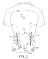
- FIG. 2 illustrates a back view of the exemplary apparel item of FIG. 1 in accordance with aspects hereof;
- FIG. 3 illustrates a front perspective view of the exemplary apparel item configured to reduce the perception of cling of FIG. 1 in an as-worn configuration in accordance with aspects hereof;
- FIG. 4 illustrates a back perspective view of the exemplary apparel item of FIG. in accordance with aspects hereof;
- FIG. 5 illustrates a close-up view of the area indicated on FIG. 1 and illustrates a plurality of perforations and a gradient in the density of the perforations in accordance with aspects hereof;
- FIG. 6 illustrates a close-up view of the area indicated on FIG. 1 and illustrates outwardly-projecting and inwardly-projecting nodes in accordance with aspects hereof;
- FIG. 7A illustrates a view of another exemplary node structure in accordance with aspects herein;
- FIG. 7B illustrates a view of another exemplary node structure having a tapered structure in accordance with aspects herein;
- FIG. 7C illustrates a view of another exemplary node structure having a tapered and exterior channeled structured in accordance with aspects herein;
- FIG. 8 illustrates a cross-sectional view taken along line 8 - 8 of FIG. 1 and illustrates outwardly-projecting and inwardly-projecting nodes in accordance with aspects hereof;
- FIG. 9 illustrates an inner-facing view of an exemplary set of outwardly-projecting and inwardly-projecting nodes in accordance with aspects hereof;
- FIG. 10 illustrates a cross-sectional view taken along line 8 - 8 of FIG. 1 and illustrates an air flow path between outwardly-projecting nodes, inwardly-projecting nodes, and a wearer's skin surface in accordance with aspects hereof;
- FIG. 11 illustrates a cross-sectional view taken along line 11 - 11 of FIG. 1 and illustrates integrated offset structures in accordance with aspects hereof;
- FIG. 12 illustrates an inner-facing view of the integrated offset structures of FIG. 10 in accordance with aspects hereof;
- FIG. 13 illustrates a flow diagram of an exemplary method of forming an apparel item configured to reduce the perception of cling in accordance with aspects hereof;
- FIG. 14 illustrates a flow diagram of an exemplary method of forming nodes on an apparel item in accordance with aspects hereof;
- FIG. 15A-15D illustrate cross-sectional views of a process for forming exemplary nodes in accordance with aspects hereof.
- FIG. 16 illustrates a front perspective view of exemplary apparel item configured to reduce the perception of cling in an as-worn configuration in accordance with aspects hereof.
- an apparel item such as a top, configured to reduce the perception of cling.
- Cling may be experienced by a wearer of an article of apparel when the article becomes sodden with sweat or other moisture (e.g., rain). This “clinging” of the article to a wearer (e.g., the wearer's skin) is often perceived to be more pronounced and therefore perceptionally worse along the side and bottom portions of the article.
- an upper torso garment such as a shirt, jersey, or top
- the wearer may complain of the garment clinging to the flank areas of the wearer (e.g., left and right lumbar region on the posterior and/or anterior portions of the wearer), which can be distracting to the wearer.
- flank areas of the wearer e.g., left and right lumbar region on the posterior and/or anterior portions of the wearer
- the configurations and structures described herein may be applied to other articles of apparel to achieve similar effects. Examples of alternative articles of apparel will be provided below when applicable.
- the apparel item described herein comprises a first set of self-standing, integrally-formed nodes projecting or extending outward from the base fabric material used to form the apparel item.
- the nodes are configured to project toward an external environment and away from a wearer's skin surface when the apparel item is in an as-worn configuration.
- the outwardly-projecting nodes may be located along right and left front side portions and right and left back side portions of the apparel item in exemplary aspects.
- the outwardly-projecting nodes located at the front side portions of the apparel item may comprise a set of apertures that are positioned on a leading edge of the nodes such that they are oriented or facing toward a front midline of the apparel item.
- the outwardly-projecting nodes located at the back side portions of the apparel item may also comprise a set of apertures. These apertures, however, may be positioned on a trailing edge of the nodes such that they are oriented or facing toward a back midline of the apparel item.
- the apparel item described herein further comprises a second set of self-standing, integrally-formed nodes that project inward from the base fabric material used to form the apparel item.
- the nodes are adapted to project toward a wearer's skin surface and away from the external environment when the apparel item is in the as-worn configuration.
- the inwardly-projecting nodes may be located between the outwardly-projecting nodes on the front side portions of the apparel item and the outwardly-projecting nodes located on the back side portions of the apparel item.
- the inwardly-projecting nodes may be located generally along side portions of the apparel item.
- the inwardly-projecting nodes may be adapted to be positioned adjacent to a mid-axillary line of the wearer.
- the inwardly-projecting nodes may not have any apertures.
- the surface area of the fabric material contacting the wearer's skin in these areas is effectively reduced.
- the configuration described reduces the surface area of the fabric material exposed to sweat which ultimately may help to reduce the perception of cling in these areas.
- the configuration described may also act as valves that allow heated air located in the space between the apparel item and the wearer's skin to escape. More specifically, air located in the space between the inner-facing surface of the apparel item and the wearer's skin surface may be heated by the wearer's intrinsic heat production. Once heated, the air may increase in volume and become more buoyant.
- the apertures located on the outwardly-projecting nodes may thus act as escape valves allowing the buoyant and heated air to escape into the external environment thereby helping to cool the wearer and potentially helping to reduce the perception of cling.
- the apertures located on the outwardly-projecting nodes may help to channel air from the external environment to the area or space between the inner-facing surface of the apparel item and the wearer's skin surface. For instance, by configuring the apertures on the outwardly-projecting nodes located along the front side portions of the apparel item to face toward the front midline, the apertures are positioned to channel wind or air flowing toward and over the front of the wearer. This type of air flow pattern often occurs when the wearer is moving (e.g., running) in a forward direction.
- the inwardly-projecting nodes which may be positioned in a honeycomb-like or staggered pattern—create channels or passages through which the air can continue to flow.
- This air flow pattern may help to speed up the rate at which the apparel item dries, which, in turn, may further reduce the wearer's perception of cling.
- the channeled air may help to cool the wearer via, for instance, evaporative cooling.
- the heating of the air by the wearer's intrinsic body heat may create convection currents that ultimately carry the air to the outwardly-projecting nodes located on, for instance, the back side portions and/or the front side portions of the apparel item by which the air can leave the interior space via the apertures located on these nodes.
- the apparel item described herein may be further configured to help reduce cling perception by comprising a plurality of perforations that extend through the thickness of the fabric material forming the apparel item.
- the perforations may be generally located over the front and back sides of the apparel item.
- the density of the perforations moreover, may be greater over the front midline and the back midline of the apparel item as these portions are positioned adjacent to high-heat producing areas of the body (e.g., the center front torso and the center back torso of the wearer).
- the perforations further help to facilitate air flow into the space between the apparel item and the wearer's body facilitating faster drying of the apparel item and helping to cool the wearer.
- the apparel item may comprise a plurality of integrated offsets structures located on an inner-facing surface of the apparel item.
- the offset structures may, in exemplary aspects, be located along the sides of the apparel item and along the bottom margins of the back and front of the apparel item.
- the offset structures may be formed through, for instance, a knitting process.
- the material used to form the apparel item may be a knit material knitted using a Jacquard knitting machine.
- the Jacquard knitting machine may be programmed to alter the stitch pattern in preconfigured areas to form the integrated offset structures.
- the offset structures may project inwardly a short distance from the base contact level of the material thus helping to “lift” the material away from the wearer's skin when the apparel item is worn.
- the size, number, and density of the offset structures may be such so as to reduce the surface area of the apparel item that comes into contact with the wearer's skin in the areas where the offset structures are located thereby helping to reduce the perception of cling.
- an apparel item for an upper torso of a wearer configured for reduced cling perception.
- the apparel item comprises a front portion and a back portion that together help to form the apparel item.
- the front portion and the back portion are formed from a fabric material having a base contact level.
- the apparel item further comprises a first set of self-standing nodes located in a first area of the apparel item, where the first set of self-standing nodes project outward from the fabric material a first distance from the base contact level. At least a portion of the first set of self-standing nodes has a plurality of apertures.
- the apparel item further comprises a second set of self-standing nodes located in a second area of the apparel item, where the second set of self-standing nodes project outward from the fabric material a second distance from the base contact level. At least a portion of the second set of self-standing nodes has a plurality of apertures.
- the apparel item additionally comprises a third set of self-standing nodes located in a third area of the apparel item, where the third set of self-standing nodes project inward from the fabric material a third distance from the base contact level.
- an apparel item for an upper torso of a wearer configured to reduce the perception of cling.
- the apparel item comprises a front and back portion formed from a knit material having a base contact level.
- the apparel item further comprises a plurality of inwardly-projecting nodes; a plurality of perforations; and a plurality of integrated offset structures located on an inner-facing surface of the apparel item.
- a method of manufacturing an apparel item configured to reduce the perception of cling.
- the method comprises providing a fabric material having a first surface and an opposite second surface; forming a first plurality of nodes on the first surface of the fabric material at one or more discrete areas of the fabric material, the first plurality of nodes projecting from the first surface of the fabric material; forming a plurality of apertures in at least a subset of the first plurality of nodes; and forming the fabric material into the apparel item.
- FIGS. 1 and 2 a front view and a back view respectively of an exemplary apparel item 100 configured to reduce the perception of cling in an un-worn configuration is illustrated in accordance with aspects herein.
- FIGS. 3 and 4 illustrate front and back perspective views respectively of the apparel item 100 in an as-worn state.
- the apparel item 100 in FIGS. 1-4 is in the form of a top having sleeves. This depiction is exemplary only, and it is contemplated that the apparel item 100 may take other forms such as a sleeveless shirt, a shirt having full-length sleeves, a jacket, and the like.
- aspects described herein may be implemented in other types of apparel items such as shorts, pants, and the like. Any and all such aspects, and any variation thereof, are contemplated as being within the scope herein.
- the apparel item 100 comprises a front portion 110 .
- the front portion 110 is adapted to cover a front torso area of the wearer when the apparel item 100 is worn as shown in FIG. 3 .
- the apparel item 100 further comprises a back portion 210 adapted to cover a back torso area of the wearer when the apparel item 100 is worn as shown in FIG. 4 .
- the front portion 110 may be affixed to the back portion 210 at one or more seams using affixing technologies known in the art such as stitching, bonding, welding, adhesives, and the like.
- the front portion 110 and the back portion 210 may be of a unitary construction such that there are little to no seams affixing the portions 110 and 210 together.
- the front portion 110 and the back portion 210 in exemplary aspects, may be made of a knitted material formed, for instance, through a Jacquard knitting process. In other exemplary aspects, the front portion 110 and the back portion 210 may be made of a woven material formed through a weaving process. Any and all aspects, and any variation thereof, are contemplated as being within the scope herein.
- the front and back portions 110 and 210 comprise a number of different structures and/or configurations designed to help reduce the perception of cling.
- both the front portion 110 and the back portion 210 comprise a plurality of perforations 112 .
- the perforations 112 extend through the thickness of the front portion 110 and the back portion 210 such that they provide a passage or communication path between an outer-facing surface of the front and back portions 110 and 210 and an inner-facing surface of the front and back portions 110 and 210 (i.e., a passage from the external environment to an interior environment such as the wearer's skin surface).
- the perforations 112 are generally located along and adjacent to a midline of the front portion 110 (e.g., a line bisecting the front portion 110 into equal right and left halves) and the midline of the back portion 210 (e.g., a line bisecting the back portion 210 into equal right and left halves), although the perforations 112 may extend to the left and right side portions of the front portion 110 and the back portion 210 . As well, the perforations 112 may extend from a collar or neckline portion of the front portion 110 and the back portion 210 to a lower margin or edge of the front portion 110 and the back portion 210 . The perforations 112 may also extend onto sleeve portions of the apparel item 100 . Any and all such aspects, and any variation thereof, are contemplated as being within the scope herein.
- the size of the perforations 112 as well as the number of perforations 112 may be variable. Further, the density of the perforations 112 may be variable. For instance, the perforations 112 may be larger in size, greater in number, and/or more densely arranged closer to the midline of the front portion 110 and the back portion 210 . Moreover, the perforations 112 may be larger in size, greater in number, and/or more densely arranged in upper portions of the front portion 110 and the back portion 210 as opposed to lower portions of the front and back portions 110 and 210 .
- FIGS. 3 and 4 show that these areas of the front portion 110 and back portion 210 are configured to lay flat against an upper front torso area of a wearer and an upper back torso of the wearer respectively as shown in FIGS. 3 and 4 , and these areas are often high heat and/or sweat-producing locations.
- the depictions of the perforations 112 in FIGS. 1 and 2 are exemplary only, and it is contemplated that other configurations and locations of the perforations 112 are within the scope herein.
- FIG. 5 depicts a close-up view of the perforations 112 in the area indicated in FIG. 1 in accordance with aspects herein.
- a close-up view of the perforations 112 on the back portion 210 would be similar, and the discussion of FIG. 5 is equally applicable to the perforations 112 located on the back portion 210 .
- the perforations 112 generally have a linear or slit-like shape although other shapes are contemplated herein such as circles, ellipses, squares, triangles, and the like.
- the perforations 112 may be formed by incising the material used to form the apparel item 100 using, for instance, mechanical cutting, laser cutting, ultrasonic cutting, water jet cutting, and the like such that the perforations 112 extend entirely through the thickness of the material.
- the perforations 112 may be engineered into the fabric material using a knitting and/or weaving process. Any and all aspects, and any variation thereof, are contemplated as being within the scope herein.
- the perforations 112 may be variably-sized with larger-sized perforations 113 being located closer to the midline of the apparel item 100 and smaller-sized perforations 115 being located away from the midline and more toward the periphery of the front portion 110 and the back portion 210 . Further, as shown in FIG. 5 , the perforations 112 may be greater in number and/or be arranged in a denser pattern closer to the midline of the apparel item 100 and be less densely arranged in areas located away from the midline. As discussed above, increasing the density and/or size of the perforations 112 toward the midline of the apparel item 100 helps to facilitate increased air flow in this area.
- this portion of the apparel item 100 is generally positioned adjacent to relatively high heat-producing areas of the wearer when worn.
- the material forming the front portion 110 and the back portion 210 may dry quicker and the wearer may cool more quickly thus helping to reduce the perception of cling.
- the front portion 110 further comprises a first set of outwardly-projecting nodes 114 .
- the first set of nodes 114 may be located generally along the right and left front side portions of the front portion 110 . These areas may generally correspond in part to the flank area of a wearer when the apparel item 100 is in the as-worn configuration as shown in FIG. 3 .
- the first set of nodes 114 may comprise between 5 to 20 ellipsoid or diamond-shaped nodes arranged in a staggered pattern as shown. In other words, the nodes 114 located closer to the midline of the front portion 110 may be offset from the nodes 114 located closer to the lateral margin of the front portion 110 .
- the number and the patterning of the first set of nodes 114 shown in FIG. 1 is exemplary only, and it is contemplated that the first set of nodes 114 may be arranged in different types of patterns and may comprise a different number than shown in FIG. 1 .
- Each of the first set of nodes 114 may comprise a number of apertures located along a leading edge of each node 114 . In other words, the apertures may be oriented on the nodes 114 such that they face toward the midline of the front portion 110 .
- FIG. 6 A more detailed description of the first set of nodes 114 , including the apertures, will be provided with respect to FIG. 6 .
- the front portion 110 also comprises a second set of inwardly-projecting nodes 116 .
- the second set of inwardly-projecting nodes 116 is located lateral to the first set of nodes 114 on both the right and left sides of the front portion 110 .
- the second set of nodes 116 may extend around the sides of the apparel item 100 to the back portion 210 as shown in FIGS. 2 and 4 .
- the second set of nodes 116 including those located on the back portion 210 , may comprise between 5 and 40 in number although numbers outside of that range are contemplated herein.
- the nodes 116 may comprise an ellipsoid or diamond shape although other shapes are contemplated herein.
- the second set of nodes 116 may be arranged in a staggered or honeycomb-like pattern similar to the first set of nodes 114 such that nodes 116 in adjacent vertical columns are offset from one another.
- the number and the patterning of the second set of nodes 116 shown in FIGS. 1-4 is exemplary only, and it is contemplated that the second set of nodes 116 may be arranged in different types of patterns and may comprise a different number than shown in FIGS. 1-4 . A more detailed description of the second set of nodes 116 will be provided with respect to FIG. 6 .
- the back portion 210 of the apparel item 100 comprises a third set of outwardly-projecting nodes 214 .
- the third set of nodes 214 may be located generally along the right and left back side portions of the back portion 210 . These areas may generally correspond in part to the flank area of a wearer when the apparel item 100 is in the as-worn configuration as shown in FIG. 4 .
- the third set of nodes 214 may comprise between 5 to 20 ellipsoid or diamond-shaped nodes arranged in a staggered pattern as shown.
- the nodes 214 located closer to the midline of the back portion 210 may be offset from the nodes 214 located closer to the lateral margin of the back portion 210 .
- the number and the patterning of the third set of nodes 214 shown in FIG. 2 is exemplary only, and it is contemplated that the third set of nodes 214 may be arranged in different types of patterns and may comprise a different number than shown in FIG. 2 .
- Each of the third set of nodes 214 may comprise a number of apertures located on a trailing edge of the node 214 . In other words, the apertures are oriented on the nodes 214 such that they face toward a midline of the back portion 210 .
- a more detailed description of the third set of nodes 214 including the apertures, will be provided with respect to FIG. 6 .
- the back portion 210 further comprises the second set of nodes 116 that wrap around from the front portion 110 of the apparel item 100 .
- the second set of nodes 116 is interposed or located between the first set of nodes 114 and the third set of nodes 214 .
- the second set of nodes 116 is located lateral to the third set of nodes 214 on both the right and left sides of the back portion 210 .
- the apparel item 100 is in the as-worn configuration as shown in FIGS. 3 and 4
- the second set of nodes 116 is generally positioned adjacent to the sides of the wearer.
- the second set of nodes 116 is configured to generally be positioned adjacent to a mid-axillary line of the wearer.
- FIG. 6 a close-up view of the nodes is provided in the areas indicated in FIG. 1 in accordance with aspects herein. Because the close-up view is the same for both the front portion 110 and the back portion 210 in this area, FIG. 6 is equally applicable to both the front portion 110 and the back portion 210 .
- the distinction between the first set of nodes 114 and the third set of nodes 214 will be noted when appropriate.
- FIG. 6 depicts a portion of the first/third set of nodes 114 / 214 and a portion of the second set of nodes 116 .
- each node 114 / 214 may be integrally formed at least in part from the material that is used to make the front portion 110 and the back portion 210 respectively and extends or projects outward from the material surface by a first distance.
- each node 114 / 214 extends toward an external environment and away from, for instance, a wearer's skin surface when the apparel item 100 is worn.
- each node 114 / 214 may be formed via an embossing process and/or each node 114 / 214 may be formed by applying an ink containing a foaming additive to the fabric forming the apparel item 100 and activating the ink.
- each node 114 / 214 may extend or project outward from the material surface a distance between, for example, 2.0 mm to 4.0 mm, 2.3 mm to 3.5 mm, and/or 2.5 mm to 3.0 mm, although distances above and below these ranges are contemplated herein.
- each node 114 / 214 may have a length, L, as measured along the long axis of the node 114 / 214 of between 1.5 cm to 2.5 cm, 1.75 cm to 2.25 cm, and/or between 1.9 cm and 2.1 cm, although lengths above and below these ranges are contemplated herein.
- Each node 114 / 214 may have a width, W, as measured across its short axis of between 1.0 cm to 2.0 cm, 1.2 cm to 1.8 cm, and/or between 1.4 cm to 1.5 cm, although widths above and below these ranges are contemplated herein. Further, each node 114 / 214 may be generally separated from an adjacent node 114 / 214 by distances in the range of 1.0 cm to 3.0 cm, 1.5 cm to 2.5 cm, and/or 1.9 cm to 2.1 cm, although distances greater than or less than these are contemplated herein.
- each node 114 / 214 may comprise a plurality of apertures 118 arranged adjacent to an edge of the node 114 / 214 .
- the apertures 118 may be located along a leading edge of the node 114 .
- the apertures 118 may be oriented on each node 114 to face toward a midline of the front portion 110 .
- the apertures 118 may be arranged generally along a midline of the node 114 , and/or generally along a trailing edge of the node 114 (i.e., oriented to face away from the midline of the front portion 110 and to face in a backward direction when the apparel item 100 is worn). Any and all aspects, and any variation thereof, are contemplated as being within the scope herein.
- the apertures 118 may be located along a trailing edge of the node 214 .
- the apertures 118 may be oriented on each node 214 to face toward a midline of the back portion 210 .
- the apertures 118 may be arranged along a midline of the node 214 , and/or along a leading edge of the node 214 (i.e., oriented to face away from the midline of the back portion 210 and to face in a forward direction when the apparel item 100 is worn). Any and all aspects, and any variation thereof, are contemplated as being within the scope herein.
- each node 114 / 214 may comprise between 2 to 8 apertures, 3 to 7 apertures, and/or between 4 to 6 apertures, although numbers greater than or less than these are contemplated herein.
- the apertures 118 may have a diameter in the range of 0.5 mm to 3.0 mm, 1.0 mm to 2.75 mm, and/or between 1.9 mm and 2.1 mm, although diameters above and below these ranges are contemplated herein.
- the apertures 118 may have a gradation in diameter such that the aperture 118 with the largest diameter is positioned centrally on its respective node, and the apertures 118 extending away from the central aperture 118 gradually decrease in diameter as shown in FIG. 6 .
- each node 116 of the second set of nodes 116 may be integrally formed from the material that is used to make the front portion 110 and back portion 210 and extends or projects inward from the material surface by a second distance. In other words, each node 116 extends away from an external environment and toward an interior environment such as a wearer's skin surface when the apparel item 100 is worn. As will be explained more fully below, each node 116 may be formed via a debossing process and/or each node 116 may be formed by applying an ink containing a foaming additive to the fabric forming the apparel item 100 and activating the ink.
- each node 116 may extend inward from the material surface a distance in the range of 2.0 mm to 4.0 mm, 2.3 mm to 3.5 mm, and/or 2.5 mm to 3.0 mm, although distances above and below these ranges are contemplated herein.
- each node 116 may have a length, L, as measured along the long axis of the node 116 of between 1.5 cm to 2.5 cm, 1.75 cm to 2.25 cm, and/or between 1.9 cm and 2.1 cm, although lengths above and below these ranges are contemplated herein.
- Each node 116 may have a width, W, as measured across its short axis of between 1.0 cm to 2.0 cm, 1.2 cm to 1.8 cm, and/or between 1.4 cm to 1.5 cm, although widths above and below these ranges are contemplated herein. Further, each node 116 may be generally separated from an adjacent node 116 by distances in the range of 1.0 cm to 3.0 cm, 1.5 cm to 2.5 cm, and/or 1.9 cm to 2.1 cm, although distances greater than or less than these are contemplated herein. In exemplary aspects, the nodes 116 may not comprise apertures such as the apertures 118 located on the first set of nodes 114 and the third set of nodes 214 . A description of the function of the nodes 114 , 116 , and 214 will be discussed later.
- FIG. 7A depicts an alternative shape configuration for the first and third set of nodes 114 and 214 and is referenced generally by the numeral 700 .
- the node 700 may comprise more of a square-like cuboid shape having distinct edges and faces.
- the dimensions of the node 700 may be generally similar to the dimensions for the nodes 114 , 116 , and 214 .
- the node 700 may extend from the fabric surface a distance in the range of 2.0 mm to 4.0 mm, 2.3 mm to 3.5 mm, and/or 2.5 mm to 3.0 mm, and may have a length/width in the range of 1.0 cm to 2.7 cm, 1.5 cm to 2.5 cm, 1.75 cm to 2.25 cm, and/or between 1.9 cm and 2.1 cm.
- a length extending between a face 712 and an opposite surface 715 may be 1.0 cm to 2.7 cm, 1.5 cm to 2.5 cm, 1.75 cm to 2.25 cm, and/or between 1.9 cm and 2.1 cm, in an exemplary aspect. Dimensions provided in association with node 700 that are above and below these ranges are contemplated herein.
- Apertures 710 may be located on the face 712 of the node 700 that is oriented toward the midline of the front portion 110 with respect to the first set of nodes 114 and toward the midline of the back portion 210 with respect to the third set of nodes 214 . Similar to the apertures 118 , the apertures 710 may vary in number and may have a gradation in diameter within the ranges set forth for the apertures 118 .
- the shape configuration depicted for the node 700 may also be used for the second set of nodes 116 excluding, for instance, the apertures 710 . Additional shape configurations are contemplated herein for the first, second, and third set of nodes 114 , 116 , and 214 respectively.
- the nodes 114 , 116 , and 214 may have more of a hemispherical configuration, a prism configuration, a rectangular cuboid-shaped configuration, conical configuration, octahedron configuration, tetrahedron configuration, cylindrical configuration, and the like. Further, the orientation of each of the node configurations relative to the fabric and/or the wearer when worn may be varied to achieve varied results as contemplated herein.
- FIG. 7B is a view of another exemplary node structure having a tapered structure in accordance with aspects herein and generally referred to by the numeral 702 .
- the node 702 may comprise more of a wedge-like triangular prism shape having distinct edges, faces, and a tapered profile.
- the dimensions of the node 702 may be generally similar to the dimensions for the nodes 114 , 116 , and 214 .
- the node 702 may extend from the fabric surface proximate the face 712 a distance 713 in the range of 2.0 mm to 4.0 mm, 2.3 mm to 3.5 mm, and/or 2.5 mm to 3.0 mm.
- the node 702 extends a lesser distance than distance 713 .
- the tapered edge 714 converges with the fabric and therefore the node 702 is flush with the fabric at the tapered edge 714 , in an exemplary aspect.
- the tapered edge 714 extends from the fabric a distance of less than 1 mm, in an exemplary aspect.
- the node 702 may have a length/width in the range of 1.0 cm to 2.7 cm, 1.5 cm to 2.5 cm, 1.75 cm to 2.25 cm, and/or between 1.9 cm and 2.1 cm.
- a length extending between the face 712 and the tapered edge 714 may be 1.0 cm to 2.7 cm, 1.5 cm to 2.5 cm, 1.75 cm to 2.25 cm, and/or between 1.9 cm and 2.1 cm, in an exemplary aspect. Dimensions provided in association with node 702 that are above and below these ranges are contemplated herein. Apertures 710 may be located on the face 712 of the node 702 that is oriented toward the midline of the front portion 110 with respect to the first set of nodes 114 and toward the midline of the back portion 210 with respect to the third set of nodes 214 .
- the apertures 710 may vary in number and may have a gradation in diameter within the ranges set forth for the apertures 118 .
- the shape configuration depicted for the node 702 may also be used for the second set of nodes 116 excluding, for instance, the apertures 710 .
- FIG. 7C is a view of another exemplary node structure having a tapered structure with an exterior channel structure in accordance with aspects herein and generally referred to by the numeral 704 .
- the node 704 may comprise more of a wedge-like triangular prism shape having distinct edges, faces, and a tapered profile.
- the dimensions of the node 704 may be generally similar to the dimensions for the node 702 .
- the node 704 may extend from the fabric surface proximate the face (not shown, but the surface on which apertures 710 are located) a distance in the range of 2.0 mm to 4.0 mm, 2.3 mm to 3.5 mm, and/or 2.5 mm to 3.0 mm.
- the node 704 extends a lesser distance than the distance at the face.
- the tapered edge 714 converges with the fabric and therefore the node 704 is flush with the fabric at the tapered edge 714 , in an exemplary aspect.
- the tapered edge 714 extends from the fabric a distance of less than 1 mm, in an exemplary aspect.
- the node 704 may have a length/width in the range of 1.0 cm to 2.7 cm, 1.5 cm to 2.5 cm, 1.75 cm to 2.25 cm, and/or between 1.9 cm and 2.1 cm.
- a length extending between the face and the tapered edge 714 may be 1.0 cm to 2.7 cm, 1.5 cm to 2.5 cm, 1.75 cm to 2.25 cm, and/or between 1.9 cm and 2.1 cm, in an exemplary aspect.
- the node 704 is depicted having a plurality of channels 716 .
- the plurality of channels extend from a top surface 718 of the node 704 to a channel surface 720 that, in this example, is recessed from the top surface 718 .
- one or more of the channels 716 extend beyond the top surface 718 as embossed rather than the depicted debossed configuration.
- the plurality of channels may align with the one or more apertures 710 to provide structural integrity to the node 704 and/or direct air movement relative to the apertures 710 , in exemplary aspects.
- an exemplary configurations is provided having a tapered channel wall 722 that has a greater depth of recession proximate the face and a lesser depth of recession proximate the tapered edge 714 .
- This tapered channel wall 722 configuration may provide fluid flow characteristics that assist in achieving aspects provided herein.
- Apertures 710 may be located on the face of the node 704 that is oriented toward the midline of the front portion 110 with respect to the first set of nodes 114 and toward the midline of the back portion 210 with respect to the third set of nodes 214 . Similar to the apertures 118 , the apertures 710 may vary in number and may have a gradation in diameter within the ranges set forth for the apertures 118 .
- the shape configuration depicted for the node 704 may also be used for the second set of nodes 116 excluding, for instance, the apertures 710 .
- the face of the node 704 is depicted having an angled surface relative to the underlying fabric (non-perpendicular). This angled approach of the face may provide for fluid flow characteristics that achieve aspects provided herein. As such, it is contemplated that a variety of node configuration may be implemented in various sizes, orientations, and structures to achieve aspects provided herein.
- FIG. 8 illustrates a cross-section of the apparel item 100 taken along cut line 8 - 8 of FIG. 1 in accordance with aspects herein.
- the apparel item 100 comprises an outer-facing surface 810 and an inner-facing surface 812 of a fabric material used to form the apparel item 100 .
- the inner-facing surface 812 is adapted to face toward, for example, a wearer's skin surface and/or a base layer worn under the apparel item 100
- the outer-facing surface 810 is adapted to face toward the external environment and/or an outer layer worn over the apparel item 100 .
- the fabric material comprises a base contact level without the nodes 114 , 116 , and 214 .
- first set of nodes 114 the second set of nodes 116 , and the third set of nodes 214 .
- first set of nodes 114 and the third set of nodes 214 extend or project outward from the base contact level of the fabric material a first distance, D 1
- second set of nodes 116 extend or project inward from the base contact level of the fabric material a second distance, D 2 .
- the first distance and the second distance may, in exemplary aspects, be the same or different.
- the apertures 118 of the first set of nodes 114 are oriented to face in a forward direction (e.g., toward the front midline of the apparel item 100 ), and the apertures 118 of the third set of nodes 214 are oriented to face in a backward direction (e.g., toward the back midline of the apparel item 100 ) when the apparel item 100 is in the as-worn configuration.
- the inner-facing surfaces 812 of each of the nodes 114 , 116 , and 214 may be reinforced with a heat-activated reinforcement material 814 .
- the reinforcement material 814 comprises a polyurethane or thermoplastic polyurethane material that is heat bonded to the inner-facing surfaces 812 of the nodes 114 , 116 , and 214 .
- the reinforcement material 814 may be bonded during an embossing process used to form the first and third set of nodes 114 and 214 and during a debossing process used to form the second set of nodes 116 . This process will be explained in greater depth below.
- the reinforcement material 814 helps to provide structural integrity to the nodes 114 , 116 , and 214 so that the nodes 114 , 116 , and 214 are self-standing and are able to withstand daily wear-and-tear including washings. As shown in FIG. 8 , the apertures 118 extend through the thickness of the reinforcement material 814 . Since the reinforcement material 814 is located on the inner-facing surface 812 of the apparel item 100 , the reinforcement material 814 may be processed to have a soft hand so as to be comfortable against the skin of the wearer.
- the reinforcement material 814 may comprise polyurethane (PU), thermoplastic polyurethane (TPU) film and/or the like.
- the texture of the reinforcement material 814 may be augmented through the texture of a carrier paper on which the reinforcement material 814 is formed.
- the PU or TPU may be extruded onto a carrier paper and the surface of the PU or TPU in contact with the carrier paper may take on a similar surface structure as that of the carrier paper.
- a texture on the carrier paper may be used to transfer the texture to the film (e.g., to achieve a buckskin-like texture on the film having a soft hand), in an exemplary aspect.
- a texture and feel may be manipulated as part of the material formation, forming/molding, or other processes steps.
- FIG. 9 depicts an exemplary inner-facing view of the nodes 114 , 116 , and 214 in accordance with aspects herein.
- This view is exemplary only, and it is contemplated that there may be a greater number of nodes 116 located between the first set of nodes 114 and the third set of nodes 214 .
- each of the first, second, and third sets of nodes 114 , 116 and 214 respectively has reinforcement material 814 bonded to its inner-facing surface 812 .
- the reinforcement material 814 comprises discrete segments, where each segment is associated with a particular node 114 , 116 , or 214 .
- the reinforcement material 814 for each node 114 , 116 , and 214 is generally formed such that it extends beyond the boundaries of the underlying node 114 , 116 , and 214 .
- FIG. 10 is a side view of a portion of the apparel item 100 comprising the nodes 114 , 116 , and 214 in relation to a skin surface of the wearer's skin 1000 of a wearer in accordance with aspects herein.
- the nodes 114 , 116 , and 214 are shown without the reinforcement material 814 , although it is contemplated that the nodes 114 , 116 and 214 may comprise the reinforcement material 814 .
- FIG. 10 is provided to illustrate how the nodes 114 , 116 , and 214 act to reduce the perception of cling by the wearer. As a first example, and as illustrated in FIG.
- use of the nodes 114 , 116 , and 214 decreases the amount of contact between the fabric material used to form the apparel item 100 and the wearer's skin 1000 in the area where the nodes 114 , 116 , and 214 are located.
- the second set of inwardly-projecting nodes 116 helps to lift the base contact level of the fabric material used to form the apparel item 100 away from the wearer's skin 1000 .
- the only contact between the apparel item 100 and the wearer's skin 1000 may be limited to the apexes of the nodes 116 .
- the fabric material By reducing the amount of contact between the fabric material forming the apparel item 100 and the wearer's skin 1000 , the fabric material is less likely to absorb perspiration produced by the wearer's skin 1000 . This helps to keep the apparel item 100 from becoming weighted down with perspiration and clinging to the wearer.
- the nodes 114 , 116 , and 214 further act to reduce the perception of cling by the wearer by facilitating air flow between the external environment and the space between the apparel item 100 and the wearer's skin 1000 .
- the apertures 118 on the first set of nodes 114 are oriented to face toward a front midline of the apparel item 100 . Physical movements by the wearer such as running often cause air to flow over the front over the wearer's torso.
- the air may flow into the apertures 118 as indicated by the arrow 1012 .
- the nodes 114 are better positioned to capture and channel this air flow as opposed to apertures that lay flat against the surface of the apparel item 100 .
- the air enters into a space or void created by the inwardly-projecting second set of nodes 116 as indicated by the arrow 1014 . More specifically, because the nodes 116 project inward, the nodes 116 create channels or passages in the space between the inner-facing surface 812 of the apparel item 100 and the wearer's skin 1000 . Air flowing through the passages or channels created by the nodes 116 and the wearer's skin 1000 helps to cool the wearer and may also effect drying of the apparel item 100 helping to reduce the perception of cling. In one aspect, the air may exit this space by leaving through the apertures 118 located on the third set of nodes 214 as indicated by the arrow 1016 .
- air flow within the channels or passages created between the inner-facing surface 812 of the apparel item 100 and the wearer's skin 1000 by the nodes 116 may be heated by the wearer's intrinsic body heat.
- the air may also pick up moisture vapor produced by the wearer's body. As the air is heated it may increase in volume and become more buoyant which may force the air out of the apertures 118 of the first and third set of nodes 114 and 214 carrying the moisture vapor with it which further helps to cool the wearer, dry the apparel item, and reduce the perception of cling.
- the front portion 110 and the back portion 210 of the apparel item 100 may further comprise a plurality of integrated offset structures 120 located generally within the boundaries defined by the dotted line 122 , the right and left margins of the apparel item 100 and the lower or bottom margins of the front portion 110 and the back portion 210 , although it is contemplated herein that the integrated offset structures 120 may extend outside of this area.
- the integrated offset structures 120 are generally located on an inner-facing surface of the front portion 110 and the back portion 210 , although an indication of the integrated offset structures 120 may appear on the outer-facing surface of the apparel item 100 as shown, for example, in FIGS. 1 and 2 . A better view of the integrated offset structures 120 is shown in FIGS. 11 and 12 .
- FIG. 11 is a cross-section taken along line 11 - 11 of FIG. 1 in accordance with aspects herein and is referenced generally by the numeral 1100 .
- FIG. 11 illustrates the outer-facing surface 810 of the apparel item 100 and the inner-facing surface 812 of the apparel item 100 .
- the plurality of integrated offset structures 120 are shown extending inwardly from the inner-facing surface 812 .
- the Jacquard knitting machine may be programmed to alter the stitch pattern in the areas indicated in FIGS. 1 and 2 to create the integrated offset structures 120 . For instance, additional stitches may be added to create the integrated offset structures 120 .
- the weaving device may be programmed to alter the weave pattern in the areas indicated in FIGS. 1 and 2 to create the integrated offset structures 120 .
- the integrated offset structures 120 extend away from the inner-facing surface 812 of the apparel item 100 in the range of 0.25 mm to 1.5 mm, 0.5 mm to 1.25 mm, and/or 0.75 mm to 1.0 mm, although distances greater than or lesser than these values are contemplated as being within the scope herein.
- FIG. 12 referenced generally by the numeral 1200 , is a perspective view of the inner-facing surface of the apparel item 100 in the areas comprising the integrated offset structures 120 and is used to illustrate the shape configuration and patterning of the integrated offset structures 120 in accordance with aspects herein.
- the integrated offset structures 120 may be configured in a diamond shape although other shape configurations are contemplated herein such as circles, triangles, squares, and the like.
- Each offset structure 120 may generally have a length and width in the range of 3.0 mm to 1.0 cm, 4.0 mm to 8.0 mm, and/or 5.0 mm to 7.0 mm, although lengths and widths greater than or lesser than these values are contemplated herein.
- the integrated offset structures 120 may be arranged in a repeating pattern where offset structures 120 in one row are offset or staggered from the offset structures 120 in an adjacent row. Each offset structure 120 may be separated from an adjacent offset structure 120 by distances in the range of 1.0 mm to 5.0 mm, 1.1 mm to 4.0 mm, and/or 1.2 mm to 3.0 mm, although distances greater than or less than these values are contemplated herein.
- the integrated offset structures 120 may be knit or woven to comprise a set of apertures 1210 located generally along a lower or inferior portion of the integrated offset structures 120 when the apparel item 100 is in an as-worn configuration.
- the apertures 1210 may impart a degree of permeability or breathability to the integrated offset structures 120 to potentially offset the increased thickness of the material in the areas where the integrated offset structures 120 are located.
- the dimensions associated with the integrated offset structures 120 along with the patterning of the integrated offset structures 120 help to decrease the amount of contact between the inner-facing surface 812 of the apparel item 100 and, for instance, the wearer's skin when the apparel item 100 is in an as-worn configuration.
- the integrated offset structures 120 generally contact the skin in the areas designated in FIGS. 1 and 2 , but those portions of the material located between the integrated offset structures 120 are held away from the wearer's skin thus effectively reducing the surface area of the material coming into contact with the wearer's skin. As explained above, this may help to reduce the perception of cling by decreasing the surface area available to absorb perspiration.
- FIG. 13 depicts a flow diagram of a first exemplary method 1300 of manufacturing an apparel item, such as the apparel item 100 , configured to reduce the perception of cling in accordance with aspects herein.
- a fabric material having a first surface and a second surface is provided.
- the fabric material may be cut to form, for instance, a front portion and a back portion of an apparel item such as the front portion 110 and the back portion 210 of the apparel item 100 .
- other formation techniques may be implemented. For example, seamless knitting or weaving may be used in whole or in part to form at least portions of the garment.
- structures may be formed integrally or as a post process to the formation of an underlying article. Therefore, while exemplary aspects are discussed specifically herein, alternative options are contemplated.
- the fabric material may comprise a knit or woven material that is knitted or woven to have a relatively tight pattern, as opposed to more of a mesh-like pattern. This helps to provide structural integrity to apparel items formed from the fabric material allowing the apparel items to withstand high amounts of wear-and-tear. However, although this may result in a sturdy apparel item, the apparel item may lack some of the breathability/permeability characteristics of apparel items formed from more mesh-like materials, hence the need to configure the apparel item to comprise some or all of the structures and configurations described herein.
- the fabric material may be knitted or woven to form integrated offset structures, such as the integrated offset structures 120 , extending from the back side of the fabric material.
- integrated offset structures may be formed in selected portions of the fabric material by adding extra stitches to offset the structures from the base contact level of the fabric material.
- the integrated offset structures 120 may be formed from molding processes, such as an integrated TPU material (e.g., yarn) that is heat formed into a desired structure, such as an offset structure.
- one or more manufacturing techniques may be implemented to integrally form the integrated offset structures 120 .
- the structures may be integrally knit or woven into the material with techniques and equipment able to achieve flat knit, circular knit, woven, and the like.
- a plurality of discrete heat-activated reinforcement material segments are applied to the second surface of the fabric material at discrete portions of the fabric material using, for example, an adhesive located on one surface of the reinforcement material segments.
- the reinforcement material segments may be on a carrier sheet, and the carrier sheet may then be applied to the second surface of the fabric material in selected portions of the fabric material.
- the reinforcement material segments When applied to the front portion and the back portion cut from the fabric material, the reinforcement material segments are applied to what will be the inner-facing surface of these portions.
- the reinforcement material segments may comprise a polyurethane or thermoplastic polyurethane film although other heat-activated films are contemplated herein.
- the heat-activated reinforcement material segments may be processed to produce a soft hand to the surface of the reinforcement material segments as these segments may come into contact with the wearer's skin when the apparel item is worn. While application of a film is provided in this exemplary aspect, it is contemplated that alternative methods and techniques may be used to achieve the creation of one or more embossed and/or debossed nodes.
- knitting technique weaving techniques, knitting machines, weaving machines, integrated materials (e.g., PU, TPU), molding, activating, pressing, and/or other forming techniques may be used in any combination to achieve the structures and/or results as provided and contemplated herein.
- integrated materials e.g., PU, TPU
- molding, activating, pressing, and/or other forming techniques may be used in any combination to achieve the structures and/or results as provided and contemplated herein.
- Another exemplary method of forming the nodes is provided below with respect to FIG. 14 and FIGS. 15A-15D .
- apertures such as the apertures 118 , may be formed on subsets of the fabric material comprising the heat-activated reinforcement material segments.
- a mechanical cutter, a laser cutter, an ultrasonic cutter, a water-jet cutter, and the like may be used to form the apertures.
- the apertures may be formed through both the fabric material and the reinforcement material segments.
- an embossing process is applied to those portions of the fabric material comprising the heat-activated reinforcement material segments and the apertures.
- the embossing process comprises applying pressure via a heated mold to the second surface of the fabric material in those portions of the fabric material comprising the heat-activated reinforcement material segments and the apertures to bond the reinforcement material segments to the fabric material while imparting a three-dimensional shape to those portions.
- the embossing process may be used to form, for example, the first set of nodes 114 and the third set of nodes 214 discussed above.
- a debossing process is applied to those portions of the fabric material comprising the heat-activated reinforcement material segments without the apertures.
- the debossing process comprises applying pressure via a heated mold to the first surface of the fabric material in those portions of the fabric material comprising the heat-activated reinforcement material segments without the apertures to bond the reinforcement material segments to the fabric material while imparting a three-dimensional shape to those portions.
- the debossing process may be used to form, for example, the second set of nodes 116 .
- the fabric material may be formed into the apparel item.
- the front portion may be affixed to the back portion at one or more seams.
- the fabric material may comprise an engineered fabric having a front portion integrally formed with the back portion with no seams.
- perforations such as the perforations 112
- perforations may be formed in selected portions of the fabric material using mechanical cutters, laser cutters, ultrasonic cutters, water-jet cutters, and the like.
- the perforations may be integrally knitted or woven into the fabric material.
- steps are depicted as discrete serial steps, it is contemplated that two or more steps may be performed in parallel.
- the embossing of step 1340 and the debossing of step 1350 may be performed simultaneously, such as through a common forming structure (e.g., a mold or dimensioned press).
- one or more steps may be omitted completely while still achieving aspects provided herein.
- the step 1320 may be omitted and instead the provided fabric material from step 1310 may have integrated materials that serve as reinforcement material to discrete portions.
- the fabric includes TPU (or similar materials) that are capable of serving as a heat activated reinforcement material without subsequent application of such materials to serve as forming and reinforcement materials, for example.
- FIG. 14 depicts a flow diagram of another exemplary method for forming nodes such as the nodes 114 , 116 , and 214 of FIGS. 1-4 .
- a fabric material is provided, where the fabric material has a first surface and a second surface opposite of the first surface.
- At a step 1412 at least a first layer of ink having a foaming additive is printed on or applied to at least a portion of the first surface of the fabric material, where the first layer of ink is applied at one or more discrete portions of the fabric material.
- the ink may be applied by utilizing a screen printing process, a 2-D printing process, a 3-D printing process, manual application, and the like.
- an optional primer layer may be applied to the first surface, where the primer layer may comprise a clear silicone-based layer with or without a foaming additive. When used, the primer layer may be partially cured before the method 1400 continues.
- the first layer of ink is partially cured to help activate the foaming additive and to help at least partially set the ink formulation.
- the method 1400 may further comprise at a step 1416 , optionally applying one or more additional layers of ink/foaming additive formulations on top of the first layer, where each layer is partially cured before application of the next layer.
- Each of the layers, including the primer layer when used, may be applied in a different pattern or the same pattern as the preceding layer. Further, each of the layers may occupy a smaller surface area than the preceding layer such that the top layer occupies the smallest surface area compared to the other layers.
- the partial-curing step may comprise exposing the ink/foaming additive formulation to a predefined temperature for a predefined period of time. Different temperatures and/or different time periods may be used for each layer or the same temperature and time period may be used for each layer. Any and all aspects, and any variation thereof, are contemplated as being within the scope herein.
- an optional top layer that may or may not have a foaming additive may be applied to help seal the resulting foam node and/or to impart a soft feel or texture to the node since the top layer may be in contact with a wearer's skin surface.
- a final curing step may be done at a step 1418 to fully set the node and to complete the activation of the foaming additive.
- the final curing step may be at a different temperature and time period than the partial curing steps (e.g., at a higher temperature and for a longer period of time).
- the partial-curing steps and the final curing step may be achieved using modalities such as infra-red light, ultrasound, radio-frequency waves, chemicals, water, ultra-violet lights, and the like. Any and all aspects, and any variation thereof, are contemplated as being within the scope herein.
- the method 1400 further contemplates forming one or more foam nodes on one or more discrete portions of the second surface of the fabric material.
- the method 1400 may further comprise perforating some or all of the foam nodes via, for instance, a mechanical process, laser cutting, water-jet cutting, ultrasonic cutting, and the like.
- FIG. 15A illustrate a cross-sectional view of a base material 1500 having an inner-facing surface 1510 and an outer-facing surface 1512 in accordance with aspects herein.
- the base material 1500 may, in exemplary aspects, have a weight between 130 gsm and 300 gsm (i.e., may be formed of a lightweight material).
- a first layer 1514 of ink having a foaming additive is printed on to the inner-facing surface 1510 of the base material 1500 .
- a partial-curing step (e.g., a flash-curing step) is then carried out as indicated by the arrow to help set the ink and to begin activation of the foaming additive.
- FIG. 15B illustrates the base material 1500 after the initial curing step.
- the first layer 1514 has expanded in all directions (e.g., in an x-direction, a y-direction, and a z-direction) due to activation of the foaming additive by the heat as indicated by the arrows in FIG. 15B .
- the first layer 1514 extends convexly away from the inner-facing surface 1510 .
- the layer 1514 may “lift” the underlying base material 1500 . This may be possible due to the lightweight and elastic nature of the material. The result is that the base material 1500 “puckers” to form a debossed region 1516 on the outer-facing surface 1512 of the base material 1500 . As shown, the debossed region 1516 extends concavely away from the outer-facing surface 1512 of the base material 1500 .
- the specific formulation of the ink and/or foaming additive, parameters associated with the curing or activation process, as well as the application pattern may be selected to achieve this deboss effect.
- FIG. 15C illustrates the base material 1500 at a point when a second layer 1518 of ink having a foaming additive (which may be the same formulation or a different formulation than the first layer 1514 ) is printed on to the surface of the first layer 1514 of partially cured ink.
- a second partial-curing step (e.g., a flash-curing step) is then carried out as indicated by the arrow.
- FIG. 15D illustrates the base material 1500 after the second curing step.
- the second layer 1518 has expanded in all directions (as indicated by the arrows) due to the activation of the foaming additive by the heat.
- the activation of the second layer 1518 may cause further lifting or puckering of the underlying base material 1500 to increase the amount of offset associated with the debossed region 1516 .
- the degree of puckering or degree of deboss of the base material 1500 may be more pronounced in areas corresponding to the second layer 1518 .
- the shape of the deboss pattern may be sculpted or modified so that greater deboss is achieved in areas corresponding to multiple layers of ink/foaming additive and lesser deboss is achieved in areas corresponding to single layers of the ink/foaming additive formulation.
- a final curing step may be carried out to set the ink and to optionally complete activation of the foaming additive.
- the height of the debossed region 1516 when combined with the height of the first and second layers 1514 and 1518 (and/or optional additional layers) may create a total stand-off height for the resulting node between a desired range as indicated above when describing the nodes 114 , 116 , and 214 . It is contemplated herein that additional layers of ink with a foaming additive may be added, while balancing comfort to the wearer, to further increase the stand-off height of the resulting node.
- the different structures described herein such as the perforations, the nodes, and the integrated offset structures may be positioned at areas of an apparel item other than those described with respect to the apparel item 100 in accordance with aspects herein.
- the different placement patterns for these structures may be dependent upon, for instance, air pressure maps of the human body, skin temperature maps of the human body, sweat maps of the human body, and/or contact maps of the human body (maps indicating parts of the body that come into contact with a loose-fitting garment averaged over several athletic positions). With respect to one or more of these maps, such as contact maps, the contact map may be for a particular sport.
- the placement of the nodes may be adjusted such that besides being positioned along the side portions of the apparel item, the nodes may also be positioned along the upper front and shoulder regions of the apparel item as contact maps may indicate a higher contact of the jersey with the basketball player's skin in these areas.
- contact maps other exemplary areas in which nodes may be located comprise, for example, the upper back portions of shirts, or jerseys, sleeve portions in areas configured to be positioned adjacent to the shoulder or deltoid area of the wearer.
- the nodes When the apparel item is in the form of a pant, the nodes may be positioned along an anterior aspect of the leg portions of the pant such that they are positioned adjacent to the quadriceps muscle group of the wearer when the pant is worn, and they may be positioned along a posterior aspect of the leg portions of the pant such that they are positioned adjacent to the calf muscles of the wearer. Any and all aspects, and any variation thereof, are contemplated as being within aspects herein. By providing stand-off in these areas, the perception of cling may be reduced thereby improving wearer comfort.
- FIG. 16 depicts a front perspective view of an exemplary apparel item 1600 in an as-worn configuration.
- the apparel item 1600 is in the form of a sleeveless jersey, although it is contemplated herein that the apparel item 1600 may comprise sleeves.
- the apparel item 1600 may be configured for use by athletes participating in the sport of basketball.
- the apparel item 1600 comprises at least a torso portion 1605 adapted to be positioned adjacent to a front and back torso area of a wearer when the apparel item 1600 is worn.
- the apparel item 1600 comprises a plurality of perforations 1610 that extend through the material forming the torso portion 1605 .
- the perforations are generally located along the front midline of the torso portion 1605 .
- the perforations 1610 may also extend along left and right side portions of the torso portion 1605 and may extend along the back midline of the torso portion 1605 .
- the perforations 1610 may extend from a collar or neckline portion of the torso portion 1605 to a lower margin or edge of the torso portion 1605 . Any and all aspects, and any variation thereof, are contemplated as being within aspects herein.
- the apparel item 1600 may comprise a plurality of integrated offset structures 1612 located on an inner-facing surface of the torso portion 1605 .
- the integrated offset structures 120 with respect to the apparel item 100 is equally applicable to the integrated offset structures 1612 .
- the location of the integrated offset structures 1612 may be similar to the location of the integrated offset structures 120 (proximate to the bottom margin of the torso portion 1605 of the apparel item 1600 and along the right and left side portions of the torso portion 1605 ).
- the apparel item 1600 may further comprise a first plurality of inwardly-facing nodes 1614 located proximate (i.e., within 2 cm to 30 cm) of the neckline of the torso portion 1605 and extending along the shoulder straps of the torso portion 1605 .
- the apparel item 1600 may also comprise a second plurality of inwardly-facing nodes 1616 extending along the right and left side portions of the torso portion 1605 . In other words, both the nodes 1614 and the nodes 1616 extend away from the fabric material forming the apparel item 1600 toward a body surface of a wearer when the apparel item 1600 is worn.
- the nodes 1614 and 1616 may not comprise perforations, although it is contemplated herein that some or all of the nodes 1614 and 1616 may be perforated.
- the nodes 1614 and 1616 may be formed using the method 1300 and/or the method 1400 . Any and all aspects, and any variation thereof, are contemplated as being within aspects herein.
Landscapes
- Engineering & Computer Science (AREA)
- Textile Engineering (AREA)
- Chemical & Material Sciences (AREA)
- Materials Engineering (AREA)
- Professional, Industrial, Or Sporting Protective Garments (AREA)
Priority Applications (5)
| Application Number | Priority Date | Filing Date | Title |
|---|---|---|---|
| US15/263,537 US10271580B2 (en) | 2015-09-14 | 2016-09-13 | Apparel item configured for reduced cling perception |
| HK18114459.5A HK1255323B (en) | 2015-09-14 | 2016-09-14 | Apparel item configured for reduced cling perception |
| PCT/US2016/051573 WO2017048743A1 (en) | 2015-09-14 | 2016-09-14 | Apparel item configured for reduced cling perception |
| CN201680059357.4A CN108135294B (zh) | 2015-09-14 | 2016-09-14 | 构造成用于减少贴附感受的服装物品 |
| EP16770175.4A EP3349606B1 (de) | 2015-09-14 | 2016-09-14 | Kleidungsartikel für verminderte wahrnehmung von enge |
Applications Claiming Priority (2)
| Application Number | Priority Date | Filing Date | Title |
|---|---|---|---|
| US201562218187P | 2015-09-14 | 2015-09-14 | |
| US15/263,537 US10271580B2 (en) | 2015-09-14 | 2016-09-13 | Apparel item configured for reduced cling perception |
Publications (2)
| Publication Number | Publication Date |
|---|---|
| US20170071275A1 US20170071275A1 (en) | 2017-03-16 |
| US10271580B2 true US10271580B2 (en) | 2019-04-30 |
Family
ID=58257718
Family Applications (1)
| Application Number | Title | Priority Date | Filing Date |
|---|---|---|---|
| US15/263,537 Active 2036-12-19 US10271580B2 (en) | 2015-09-14 | 2016-09-13 | Apparel item configured for reduced cling perception |
Country Status (4)
| Country | Link |
|---|---|
| US (1) | US10271580B2 (de) |
| EP (1) | EP3349606B1 (de) |
| CN (1) | CN108135294B (de) |
| WO (1) | WO2017048743A1 (de) |
Cited By (4)
| Publication number | Priority date | Publication date | Assignee | Title |
|---|---|---|---|---|
| US20180295902A1 (en) * | 2011-03-03 | 2018-10-18 | Nike, Inc. | Sports garments with enhanced visual and/or moisture management properties |
| USD981682S1 (en) * | 2021-07-28 | 2023-03-28 | Nike, Inc. | Garment |
| USD991625S1 (en) * | 2021-07-28 | 2023-07-11 | Nike, Inc. | Garment |
| USD996777S1 (en) * | 2021-07-28 | 2023-08-29 | Nike, Inc. | Garment |
Families Citing this family (24)
| Publication number | Priority date | Publication date | Assignee | Title |
|---|---|---|---|---|
| US7437774B2 (en) | 2004-03-19 | 2008-10-21 | Nike, Inc. | Article of apparel incorporating a zoned modifiable textile structure |
| US9332792B2 (en) * | 2005-02-17 | 2016-05-10 | Nike, Inc. | Articles of apparel utilizing targeted venting or heat retention zones that may be defined based on thermal profiles |
| US9056662B2 (en) * | 2012-02-29 | 2015-06-16 | Nike, Inc. | Wetsuits with hydrodynamic interlocking and kinesiologic features |
| DE102014110623A1 (de) * | 2014-07-28 | 2016-01-28 | Hexonia Gmbh | Textiles Bekleidungsstück mit einer ballistischen Schutzausrüstung |
| US20160338435A1 (en) * | 2015-05-22 | 2016-11-24 | Nike, Inc. | Lower body article of apparel having dynamic vent-slit structure |
| US10814514B2 (en) | 2015-05-22 | 2020-10-27 | Nike, Inc. | Method of manufacturing an article of apparel having dynamic vent-slits |
| US10716340B2 (en) * | 2015-05-27 | 2020-07-21 | Nike, Inc. | System and device for affecting drag properties of an object |
| US10285463B2 (en) * | 2016-01-11 | 2019-05-14 | Nike, Inc. | Apparel item with integrated parachute structure |
| US10264834B2 (en) * | 2016-03-25 | 2019-04-23 | Nike, Inc. | Foam nodes for creating stand off on apparel items |
| BR112018071706A2 (pt) * | 2016-04-21 | 2019-02-19 | O&M Halyard International Unlimited Company | estrutura com múltiplas camadas resistente a espirros e artigo |
| EP3525611B1 (de) | 2016-09-28 | 2023-10-25 | Under Armour, Inc. | Bekleidung für sportliche aktivitäten |
| US20180343932A1 (en) * | 2017-05-30 | 2018-12-06 | Nike, Inc. | Garment With Wipe Zones |
| US10383381B2 (en) * | 2017-07-12 | 2019-08-20 | Joel F. Price | Glove |
| USD820604S1 (en) * | 2017-10-20 | 2018-06-19 | Nike, Inc. | Garment |
| USD819982S1 (en) * | 2017-10-20 | 2018-06-12 | Nike, Inc. | Garment |
| IT201800001151A1 (it) * | 2018-01-17 | 2019-07-17 | Pro Eight S R L | Struttura di indumento. |
| CN109497635A (zh) * | 2018-12-18 | 2019-03-22 | 浙江理工大学 | 一种湿态舒适的功能服装及其制造方法 |
| CN110150775B (zh) * | 2019-04-29 | 2021-05-14 | 匹克(中国)有限公司 | 一种马拉松男士专用t恤 |
| US11559092B2 (en) | 2019-08-12 | 2023-01-24 | Nike, Inc. | Apparel with dynamic vent structure |
| US12167761B2 (en) | 2019-08-12 | 2024-12-17 | Nike, Inc. | Apparel with dynamic vent structure |
| US12268256B1 (en) * | 2019-09-17 | 2025-04-08 | B J Zarcone | Wearable fogging apparatus |
| US12150495B2 (en) * | 2020-04-30 | 2024-11-26 | Ishi Studios Inc. | Seamless male garment |
| US11785999B2 (en) | 2020-05-19 | 2023-10-17 | Nike, Inc. | Garment with adaptive stand-off features |
| CN118716715A (zh) * | 2024-06-17 | 2024-10-01 | 苏州闰博尔纺织科技有限公司 | 一种四针床编织的全成形滑雪压缩服及其编织方法 |
Citations (85)
| Publication number | Priority date | Publication date | Assignee | Title |
|---|---|---|---|---|
| US2738566A (en) * | 1955-05-17 | 1956-03-20 | Carter William Co | Puckered knit fabric and method of producing same |
| GB1447173A (en) | 1973-08-20 | 1976-08-25 | Nijverdal Ten Cate Textiel | Warp knitted interlining material |
| US4057981A (en) * | 1976-12-02 | 1977-11-15 | Crescent Hosiery Mills | Ventilated cushion foot sock and method |
| US4451934A (en) * | 1981-10-16 | 1984-06-05 | Gioello Debbie A | Ribbed ventilating undergarment for protective garments |
| GB2193429A (en) * | 1986-08-07 | 1988-02-10 | Nick Gracey | Thermoregulatory clothing |
| US5547733A (en) | 1995-06-02 | 1996-08-20 | Malden Mills Industries, Inc. | Plaited double-knit fabric |
| JPH1053941A (ja) * | 1996-06-05 | 1998-02-24 | Asahi Chem Ind Co Ltd | 清涼性を有する布帛 |
| US5724673A (en) | 1993-11-12 | 1998-03-10 | Lion Apparel, Inc. | Firefighter garment with low friction liner system including patches |
| US5809567A (en) * | 1996-02-02 | 1998-09-22 | Jacobs; David L. | Method and system for reducing drag on the movement of bluff bodies through a fluid medium and increasing heat transfer |
| US5829057A (en) * | 1994-03-24 | 1998-11-03 | Robert T. Gunn | Low friction outer apparel |
| US5913406A (en) * | 1995-02-21 | 1999-06-22 | Molnlycke Health Care Ab | Surgical coat |
| KR19990037414U (ko) * | 1998-03-02 | 1999-10-05 | 박윤수 | 방충 옷 |
| JPH11302939A (ja) * | 1998-04-20 | 1999-11-02 | Toray Ind Inc | 衣料用インナー |
| KR20000012332A (ko) * | 1999-11-26 | 2000-03-06 | 이세희 | 통풍 미니런닝셔츠 |
| JP2000158577A (ja) * | 1998-09-21 | 2000-06-13 | Falcon Technology:Kk | 2層構造の布、および衣服 |
| GB2344738A (en) * | 2000-02-22 | 2000-06-21 | Michael Alec Ralph Willans | Upper body garment with thermal insulation |
| JP2001081607A (ja) * | 1999-09-13 | 2001-03-27 | Wacoal Corp | 肌に接して着用される衣料 |
| US6276178B1 (en) * | 2000-05-05 | 2001-08-21 | Liberty Fabrics | Open mesh fabric structure with stand-off design |
| EP1241286A1 (de) * | 2001-03-05 | 2002-09-18 | Karin Co., Ltd | Miederware |
| WO2002089616A1 (en) * | 2001-04-25 | 2002-11-14 | Wacoal Corporation | Wear having insulating portion |
| US20030077967A1 (en) * | 2001-10-23 | 2003-04-24 | Moshe Rock | Enhanced composite sweatshirt fabric with knit constructed channels |
| JP2003147605A (ja) * | 2001-11-13 | 2003-05-21 | Toray Ind Inc | 衣料製品 |
| US20030101776A1 (en) * | 2001-09-28 | 2003-06-05 | Fumio Shirasaki | Three dimensional knitted fabric having unevenness |
| JP2003239102A (ja) * | 2002-02-08 | 2003-08-27 | Traders Japan:Kk | 衣 服 |
| JP2004204411A (ja) * | 2002-12-26 | 2004-07-22 | Kanebo Ltd | インナー・ウェア |
| WO2004064554A1 (de) * | 2003-01-24 | 2004-08-05 | Empa St. Gallen | Kühlendes kleidungsstück für sportler |
| US20050126229A1 (en) * | 2002-06-21 | 2005-06-16 | Asahi Kasei Fibers Corporation | Cloth |
| US20050204449A1 (en) * | 2004-03-19 | 2005-09-22 | Nike, Inc. | Article of apparel incorporating a zoned modifiable textile structure |
| JP2006028648A (ja) * | 2004-07-12 | 2006-02-02 | Iida Kutsushita Kk | 衣料 |
| JP2006037310A (ja) * | 2004-07-30 | 2006-02-09 | Descente Ltd | 流体抵抗減少衣服 |
| US20060037154A1 (en) | 2004-08-19 | 2006-02-23 | Goineau Andre M | Multi-colored pile fabric and process |
| US20060070162A1 (en) * | 2004-09-28 | 2006-04-06 | Frank Ronald H | Self-ventilating body-worn articles |
| US20060080754A1 (en) * | 2004-10-14 | 2006-04-20 | Nike, Inc. | Article of apparel incorporating an embossed material |
| US7043766B1 (en) * | 2002-09-02 | 2006-05-16 | Enventys, Llc | Garment for cooling and insulating |
| US20060179539A1 (en) * | 2005-02-17 | 2006-08-17 | Nike Uk Ltd. | Articles of apparel utilizing targeted venting or heat retention zones that may be defined based on thermal profiles |
| US20060277950A1 (en) * | 2005-05-19 | 2006-12-14 | Moshe Rock | Engineered fabric articles |
| US20070033696A1 (en) * | 2004-02-11 | 2007-02-15 | Dominique Sellier | Garment serving to combat cellulite and/or venous and lymphatic insufficiency |
| US20070094762A1 (en) * | 2005-10-19 | 2007-05-03 | Nike, Inc. | Article of apparel with material elements having a reversible structure |
| DE202007004756U1 (de) * | 2007-03-29 | 2007-05-24 | Hubert Schmitz Gmbh & Co. Kg | Bekleidungsstück |
| US20070144221A1 (en) * | 2005-02-23 | 2007-06-28 | Sytz Ronald M | 3-D fabric knitted stretch spacer material having molded domed patterns and method of making |
| EP1806061A1 (de) | 2006-01-10 | 2007-07-11 | Wangbunyen Tanakorn | Verfahren zur Herstellung von Lufteinschnitten auf einem flexiblen Substrat mit Chemikalien zur Regulierung der Öffnung der Lufteinschnitten und so hergestelltes Substrat |
| US20070220673A1 (en) * | 2006-03-24 | 2007-09-27 | Susan Nichols | Clothing articles having raised projections |
| US20070293106A1 (en) * | 2006-06-19 | 2007-12-20 | Nike, Inc. | Fabrics and articles of apparel including dimensionalized mesh and other fabrics |
| CN200994420Y (zh) * | 2007-01-25 | 2007-12-26 | 上海市民办文绮中学 | 一种透气运动t恤衫 |
| JP2008038259A (ja) * | 2006-08-01 | 2008-02-21 | Karin:Kk | 衣類 |
| US20080075850A1 (en) * | 2006-06-09 | 2008-03-27 | Moshe Rock | Temperature responsive smart textile |
| KR100828077B1 (ko) * | 2007-02-05 | 2008-05-07 | 신현길 | 방충복용 원단구조 |
| WO2008069522A1 (en) * | 2006-12-04 | 2008-06-12 | Seung Gyun Woo | A knitting and inner wear |
| US20080189824A1 (en) * | 2004-06-24 | 2008-08-14 | Malden Mills Industries, Inc. | Engineered Fabric Articles |
| US20080189839A1 (en) | 2004-09-23 | 2008-08-14 | X-Technology Swiss Gmbh | Piece of Garment |
| JP2008214775A (ja) * | 2007-02-28 | 2008-09-18 | Pip Fujimoto Co Ltd | 衣類用の編地 |
| US20080289078A1 (en) * | 2007-05-08 | 2008-11-27 | Nike, Inc. | Articles of Apparel Including Zones Having Increased Thermally Insulative and Thermally Resistive Properties |
| US20090031486A1 (en) * | 2007-08-02 | 2009-02-05 | Nike, Inc. | Articles Of Base Layer Apparel Including Zones Having Different Thermal Properties |
| US20090104404A1 (en) * | 2006-03-21 | 2009-04-23 | Geox S.P.A. | Fabric, particularly for items of clothing and shoes |
| US20090276936A1 (en) * | 2006-01-17 | 2009-11-12 | Seiren Co., Ltd. | Shape changeable textile fabric |
| US20100064415A1 (en) * | 2005-09-30 | 2010-03-18 | Nike, Inc. | Article Of Apparel With Zonal Stretch Resistance |
| US7737056B2 (en) | 2007-03-05 | 2010-06-15 | Shih-Chieh Chang | Moisture-wicking and fast drying cloth |
| US20110099680A1 (en) * | 2009-10-22 | 2011-05-05 | Josh Robert Gordon | Apparel |
| US20110177294A1 (en) * | 2010-01-19 | 2011-07-21 | Mmi-Ipco, Llc | Composite textile fabrics |
| US20110239350A1 (en) * | 2010-03-15 | 2011-10-06 | Chu Po Ho | Ventilated Garment |
| CN202023101U (zh) * | 2011-02-28 | 2011-11-02 | 赵振宇 | 泡泡衬衫面料 |
| CN102650105A (zh) * | 2011-02-28 | 2012-08-29 | 赵振宇 | 泡泡衬衫面料 |
| US20130078415A1 (en) * | 2006-06-09 | 2013-03-28 | Mmi-Ipco, Llc | Temperature Responsive Smart Textile |
| US20130074250A1 (en) * | 2008-04-09 | 2013-03-28 | Lion Apparel, Inc. | Protective garment with low friction characteristics |
| JP2013067910A (ja) * | 2011-09-22 | 2013-04-18 | Gunze Ltd | インナーウエア |
| US20130133123A1 (en) * | 2007-02-09 | 2013-05-30 | Nike, Inc. | Apparel with Reduced Drag Coefficient |
| US8479322B2 (en) | 2009-05-07 | 2013-07-09 | Columbia Sportswear North America, Inc. | Zoned functional fabrics |
| US20130178146A1 (en) | 2012-01-10 | 2013-07-11 | Ryan C. Stockett | Auto-ventilated outerwear |
| US20130212767A1 (en) * | 2009-06-24 | 2013-08-22 | Nike, Inc. | Aerodynamic Garment With Applied Edge Treatments |
| US20130247268A1 (en) * | 2010-12-01 | 2013-09-26 | Toray Industries, Inc | Woven fabric for swimsuits, and swimsuit |
| US8555414B2 (en) | 2004-05-06 | 2013-10-15 | Nike, Inc. | Article of apparel utilizing zoned venting and/or other body cooling features or methods |
| CN103815556A (zh) * | 2012-11-16 | 2014-05-28 | 季建良 | 泡泡衬衫导湿透气面料 |
| CN103815558A (zh) * | 2012-11-16 | 2014-05-28 | 徐浩 | 泡泡衬衫弹性面料 |
| US20140259276A1 (en) | 2013-03-15 | 2014-09-18 | Alyx Fier | Breathable garment |
| US20140310847A1 (en) * | 2013-04-19 | 2014-10-23 | Helly Hansen As | Garment with an incorporated micro climate system |
| CN104621719A (zh) * | 2013-11-10 | 2015-05-20 | 江苏金丝狐服饰有限公司 | 具有网格状透气部的男士衬衣 |
| US20150366281A1 (en) * | 2013-01-30 | 2015-12-24 | Miller D. Stephen | Resilient prominence fabric and articles made therefrom |
| US20160050981A1 (en) * | 2014-08-20 | 2016-02-25 | Susan Costa | Textured Undergarment |
| US20160192723A1 (en) * | 2015-01-05 | 2016-07-07 | Xiaoyi Zhu | Clothing and clothing article |
| US20160302495A1 (en) * | 2015-04-20 | 2016-10-20 | Smart Aero Technology Limited | Low drag garment |
| US20160302494A1 (en) * | 2015-04-20 | 2016-10-20 | Smart Aero Technology Limited | Low drag garment |
| US9635889B1 (en) * | 2013-03-14 | 2017-05-02 | Tda Research, Inc. | Cooling garment |
| US20170340037A1 (en) * | 2016-05-31 | 2017-11-30 | Nike, Inc. | Apparel Thermo-Regulatory System |
| US20170354266A1 (en) * | 2014-12-02 | 2017-12-14 | Climazleeper Holding Aps | A ventilation or heating/cooling element and a ventilation or heating/cooling clothing item |
| US20180035727A1 (en) * | 2015-01-13 | 2018-02-08 | Under Armour, Inc. | Suit For Athletic Activities |
Family Cites Families (7)
| Publication number | Priority date | Publication date | Assignee | Title |
|---|---|---|---|---|
| GB9827412D0 (en) * | 1998-12-11 | 1999-02-03 | Middleton Nigel J | Breathable articles and fabrics |
| US6459378B2 (en) * | 1999-01-29 | 2002-10-01 | Innotek, Inc. | Animal shock collar with low impedance transformer |
| ITPD20010016A1 (it) * | 2001-01-24 | 2002-07-24 | Nottington Holding Bv | Dispositivo di aerazione da applicare su capi di vestiario per la traspirazione del corpo umano e procedimento per la produzione di detto di |
| US20030203691A1 (en) * | 2002-04-30 | 2003-10-30 | Kimberly-Clark Worldwide, Inc. | Nonwoven materials having surface features |
| AT7525U1 (de) * | 2004-04-01 | 2005-04-25 | Physiotherm Gmbh | Heizeinrichtung |
| CN102666990A (zh) * | 2009-12-23 | 2012-09-12 | Sca卫生用品公司 | 用于生产诸如纸或无纺物的柔性材料的多层幅的方法 |
| CN102754475B (zh) * | 2012-04-17 | 2015-04-29 | 华为技术有限公司 | 确定协同多点传输的协作集的方法、装置 |
-
2016
- 2016-09-13 US US15/263,537 patent/US10271580B2/en active Active
- 2016-09-14 WO PCT/US2016/051573 patent/WO2017048743A1/en not_active Ceased
- 2016-09-14 EP EP16770175.4A patent/EP3349606B1/de active Active
- 2016-09-14 CN CN201680059357.4A patent/CN108135294B/zh active Active
Patent Citations (93)
| Publication number | Priority date | Publication date | Assignee | Title |
|---|---|---|---|---|
| US2738566A (en) * | 1955-05-17 | 1956-03-20 | Carter William Co | Puckered knit fabric and method of producing same |
| GB1447173A (en) | 1973-08-20 | 1976-08-25 | Nijverdal Ten Cate Textiel | Warp knitted interlining material |
| US4057981A (en) * | 1976-12-02 | 1977-11-15 | Crescent Hosiery Mills | Ventilated cushion foot sock and method |
| US4451934A (en) * | 1981-10-16 | 1984-06-05 | Gioello Debbie A | Ribbed ventilating undergarment for protective garments |
| GB2193429A (en) * | 1986-08-07 | 1988-02-10 | Nick Gracey | Thermoregulatory clothing |
| US5724673A (en) | 1993-11-12 | 1998-03-10 | Lion Apparel, Inc. | Firefighter garment with low friction liner system including patches |
| US5829057A (en) * | 1994-03-24 | 1998-11-03 | Robert T. Gunn | Low friction outer apparel |
| US5913406A (en) * | 1995-02-21 | 1999-06-22 | Molnlycke Health Care Ab | Surgical coat |
| US5547733A (en) | 1995-06-02 | 1996-08-20 | Malden Mills Industries, Inc. | Plaited double-knit fabric |
| US5809567A (en) * | 1996-02-02 | 1998-09-22 | Jacobs; David L. | Method and system for reducing drag on the movement of bluff bodies through a fluid medium and increasing heat transfer |
| JPH1053941A (ja) * | 1996-06-05 | 1998-02-24 | Asahi Chem Ind Co Ltd | 清涼性を有する布帛 |
| KR19990037414U (ko) * | 1998-03-02 | 1999-10-05 | 박윤수 | 방충 옷 |
| JPH11302939A (ja) * | 1998-04-20 | 1999-11-02 | Toray Ind Inc | 衣料用インナー |
| JP2000158577A (ja) * | 1998-09-21 | 2000-06-13 | Falcon Technology:Kk | 2層構造の布、および衣服 |
| JP2001081607A (ja) * | 1999-09-13 | 2001-03-27 | Wacoal Corp | 肌に接して着用される衣料 |
| KR20000012332A (ko) * | 1999-11-26 | 2000-03-06 | 이세희 | 통풍 미니런닝셔츠 |
| GB2344738A (en) * | 2000-02-22 | 2000-06-21 | Michael Alec Ralph Willans | Upper body garment with thermal insulation |
| US6276178B1 (en) * | 2000-05-05 | 2001-08-21 | Liberty Fabrics | Open mesh fabric structure with stand-off design |
| US20010042388A1 (en) * | 2000-05-05 | 2001-11-22 | West Roger Donald | Fabric structure with stand-off design |
| EP1241286A1 (de) * | 2001-03-05 | 2002-09-18 | Karin Co., Ltd | Miederware |
| WO2002089616A1 (en) * | 2001-04-25 | 2002-11-14 | Wacoal Corporation | Wear having insulating portion |
| US20030101776A1 (en) * | 2001-09-28 | 2003-06-05 | Fumio Shirasaki | Three dimensional knitted fabric having unevenness |
| US20030077967A1 (en) * | 2001-10-23 | 2003-04-24 | Moshe Rock | Enhanced composite sweatshirt fabric with knit constructed channels |
| US6927182B2 (en) | 2001-10-23 | 2005-08-09 | Malden Mills Industries, Inc. | Enhanced composite sweatshirt fabric with knit constructed channels |
| JP2003147605A (ja) * | 2001-11-13 | 2003-05-21 | Toray Ind Inc | 衣料製品 |
| JP2003239102A (ja) * | 2002-02-08 | 2003-08-27 | Traders Japan:Kk | 衣 服 |
| US20050126229A1 (en) * | 2002-06-21 | 2005-06-16 | Asahi Kasei Fibers Corporation | Cloth |
| US7043766B1 (en) * | 2002-09-02 | 2006-05-16 | Enventys, Llc | Garment for cooling and insulating |
| JP2004204411A (ja) * | 2002-12-26 | 2004-07-22 | Kanebo Ltd | インナー・ウェア |
| WO2004064554A1 (de) * | 2003-01-24 | 2004-08-05 | Empa St. Gallen | Kühlendes kleidungsstück für sportler |
| US20070033696A1 (en) * | 2004-02-11 | 2007-02-15 | Dominique Sellier | Garment serving to combat cellulite and/or venous and lymphatic insufficiency |
| US20050204449A1 (en) * | 2004-03-19 | 2005-09-22 | Nike, Inc. | Article of apparel incorporating a zoned modifiable textile structure |
| US20140310846A1 (en) * | 2004-03-19 | 2014-10-23 | Nike, Inc. | Article Of Apparel Incorporating A Zoned Modifiable Textile Structure |
| US8555414B2 (en) | 2004-05-06 | 2013-10-15 | Nike, Inc. | Article of apparel utilizing zoned venting and/or other body cooling features or methods |
| US20080189824A1 (en) * | 2004-06-24 | 2008-08-14 | Malden Mills Industries, Inc. | Engineered Fabric Articles |
| JP2006028648A (ja) * | 2004-07-12 | 2006-02-02 | Iida Kutsushita Kk | 衣料 |
| JP2006037310A (ja) * | 2004-07-30 | 2006-02-09 | Descente Ltd | 流体抵抗減少衣服 |
| US20060037154A1 (en) | 2004-08-19 | 2006-02-23 | Goineau Andre M | Multi-colored pile fabric and process |
| US20080189839A1 (en) | 2004-09-23 | 2008-08-14 | X-Technology Swiss Gmbh | Piece of Garment |
| US20060070162A1 (en) * | 2004-09-28 | 2006-04-06 | Frank Ronald H | Self-ventilating body-worn articles |
| US20060080754A1 (en) * | 2004-10-14 | 2006-04-20 | Nike, Inc. | Article of apparel incorporating an embossed material |
| US20060179539A1 (en) * | 2005-02-17 | 2006-08-17 | Nike Uk Ltd. | Articles of apparel utilizing targeted venting or heat retention zones that may be defined based on thermal profiles |
| US20070144221A1 (en) * | 2005-02-23 | 2007-06-28 | Sytz Ronald M | 3-D fabric knitted stretch spacer material having molded domed patterns and method of making |
| US20060277950A1 (en) * | 2005-05-19 | 2006-12-14 | Moshe Rock | Engineered fabric articles |
| US7428772B2 (en) | 2005-05-19 | 2008-09-30 | Mmi-Ipco, Llc | Engineered fabric articles |
| US20100064415A1 (en) * | 2005-09-30 | 2010-03-18 | Nike, Inc. | Article Of Apparel With Zonal Stretch Resistance |
| US20070094762A1 (en) * | 2005-10-19 | 2007-05-03 | Nike, Inc. | Article of apparel with material elements having a reversible structure |
| EP1806061A1 (de) | 2006-01-10 | 2007-07-11 | Wangbunyen Tanakorn | Verfahren zur Herstellung von Lufteinschnitten auf einem flexiblen Substrat mit Chemikalien zur Regulierung der Öffnung der Lufteinschnitten und so hergestelltes Substrat |
| US20090276936A1 (en) * | 2006-01-17 | 2009-11-12 | Seiren Co., Ltd. | Shape changeable textile fabric |
| US20090104404A1 (en) * | 2006-03-21 | 2009-04-23 | Geox S.P.A. | Fabric, particularly for items of clothing and shoes |
| US20070220673A1 (en) * | 2006-03-24 | 2007-09-27 | Susan Nichols | Clothing articles having raised projections |
| US8187984B2 (en) | 2006-06-09 | 2012-05-29 | Malden Mills Industries, Inc. | Temperature responsive smart textile |
| US20130078415A1 (en) * | 2006-06-09 | 2013-03-28 | Mmi-Ipco, Llc | Temperature Responsive Smart Textile |
| US20080075850A1 (en) * | 2006-06-09 | 2008-03-27 | Moshe Rock | Temperature responsive smart textile |
| US8133824B2 (en) | 2006-06-19 | 2012-03-13 | Nike, Inc. | Fabrics and articles of apparel including dimensionalized mesh and other fabrics |
| US20070293106A1 (en) * | 2006-06-19 | 2007-12-20 | Nike, Inc. | Fabrics and articles of apparel including dimensionalized mesh and other fabrics |
| JP2008038259A (ja) * | 2006-08-01 | 2008-02-21 | Karin:Kk | 衣類 |
| WO2008069522A1 (en) * | 2006-12-04 | 2008-06-12 | Seung Gyun Woo | A knitting and inner wear |
| CN200994420Y (zh) * | 2007-01-25 | 2007-12-26 | 上海市民办文绮中学 | 一种透气运动t恤衫 |
| KR100828077B1 (ko) * | 2007-02-05 | 2008-05-07 | 신현길 | 방충복용 원단구조 |
| US20130133123A1 (en) * | 2007-02-09 | 2013-05-30 | Nike, Inc. | Apparel with Reduced Drag Coefficient |
| JP2008214775A (ja) * | 2007-02-28 | 2008-09-18 | Pip Fujimoto Co Ltd | 衣類用の編地 |
| US7737056B2 (en) | 2007-03-05 | 2010-06-15 | Shih-Chieh Chang | Moisture-wicking and fast drying cloth |
| DE202007004756U1 (de) * | 2007-03-29 | 2007-05-24 | Hubert Schmitz Gmbh & Co. Kg | Bekleidungsstück |
| US20080289078A1 (en) * | 2007-05-08 | 2008-11-27 | Nike, Inc. | Articles of Apparel Including Zones Having Increased Thermally Insulative and Thermally Resistive Properties |
| US20090031486A1 (en) * | 2007-08-02 | 2009-02-05 | Nike, Inc. | Articles Of Base Layer Apparel Including Zones Having Different Thermal Properties |
| US20130074250A1 (en) * | 2008-04-09 | 2013-03-28 | Lion Apparel, Inc. | Protective garment with low friction characteristics |
| US8650668B2 (en) | 2008-04-09 | 2014-02-18 | Lion Apparel, Inc. | Protective garment with low friction characteristics |
| US8479322B2 (en) | 2009-05-07 | 2013-07-09 | Columbia Sportswear North America, Inc. | Zoned functional fabrics |
| US20130212767A1 (en) * | 2009-06-24 | 2013-08-22 | Nike, Inc. | Aerodynamic Garment With Applied Edge Treatments |
| US8910313B2 (en) | 2009-10-22 | 2014-12-16 | Adidas Ag | Apparel |
| US20110099680A1 (en) * | 2009-10-22 | 2011-05-05 | Josh Robert Gordon | Apparel |
| US20110177294A1 (en) * | 2010-01-19 | 2011-07-21 | Mmi-Ipco, Llc | Composite textile fabrics |
| US20110239350A1 (en) * | 2010-03-15 | 2011-10-06 | Chu Po Ho | Ventilated Garment |
| US20130247268A1 (en) * | 2010-12-01 | 2013-09-26 | Toray Industries, Inc | Woven fabric for swimsuits, and swimsuit |
| CN102650105A (zh) * | 2011-02-28 | 2012-08-29 | 赵振宇 | 泡泡衬衫面料 |
| CN202023101U (zh) * | 2011-02-28 | 2011-11-02 | 赵振宇 | 泡泡衬衫面料 |
| JP2013067910A (ja) * | 2011-09-22 | 2013-04-18 | Gunze Ltd | インナーウエア |
| US20130178146A1 (en) | 2012-01-10 | 2013-07-11 | Ryan C. Stockett | Auto-ventilated outerwear |
| CN103815556A (zh) * | 2012-11-16 | 2014-05-28 | 季建良 | 泡泡衬衫导湿透气面料 |
| CN103815558A (zh) * | 2012-11-16 | 2014-05-28 | 徐浩 | 泡泡衬衫弹性面料 |
| US20150366281A1 (en) * | 2013-01-30 | 2015-12-24 | Miller D. Stephen | Resilient prominence fabric and articles made therefrom |
| US9635889B1 (en) * | 2013-03-14 | 2017-05-02 | Tda Research, Inc. | Cooling garment |
| US20140259276A1 (en) | 2013-03-15 | 2014-09-18 | Alyx Fier | Breathable garment |
| US20140310847A1 (en) * | 2013-04-19 | 2014-10-23 | Helly Hansen As | Garment with an incorporated micro climate system |
| CN104621719A (zh) * | 2013-11-10 | 2015-05-20 | 江苏金丝狐服饰有限公司 | 具有网格状透气部的男士衬衣 |
| US20160050981A1 (en) * | 2014-08-20 | 2016-02-25 | Susan Costa | Textured Undergarment |
| US20170354266A1 (en) * | 2014-12-02 | 2017-12-14 | Climazleeper Holding Aps | A ventilation or heating/cooling element and a ventilation or heating/cooling clothing item |
| US20160192723A1 (en) * | 2015-01-05 | 2016-07-07 | Xiaoyi Zhu | Clothing and clothing article |
| US20180035727A1 (en) * | 2015-01-13 | 2018-02-08 | Under Armour, Inc. | Suit For Athletic Activities |
| US20160302495A1 (en) * | 2015-04-20 | 2016-10-20 | Smart Aero Technology Limited | Low drag garment |
| US20160302494A1 (en) * | 2015-04-20 | 2016-10-20 | Smart Aero Technology Limited | Low drag garment |
| US20170340037A1 (en) * | 2016-05-31 | 2017-11-30 | Nike, Inc. | Apparel Thermo-Regulatory System |
Non-Patent Citations (5)
| Title |
|---|
| "A New Method for Designing Sportswear by Using Three Dimensional Computer Graphic Based Anisotropic Hyperlastic Models and Musculoskeletal Simulations", www.sciencedirect.com Last accessed Jul. 3, 2015 at: http://www.sciencedirect.com/science/article/pii/S187770581301120X. |
| "Natural Workout Wear-prevents skin irritation and unwanted odors"; soulintraining.wordpress.com Last accessed Jul. 3, 2015 at: https://soulintraining.wordpress.com/category/philippine-star-column/page/5/. |
| "Performance. Strength. Confidence." www.marenagroup.com Last accessed Jul. 3, 2015 at: https://www.marenagroup.com/athletics8/pages/why-marena/how-it-works.html. |
| International Preliminary Report on Patentability dated Mar. 29, 2018 in International Patent Application No. PCT/US2016/051573, 13 pages. |
| International Search Report and Written Opinion dated Feb. 22, 2017 in International Patent Application No. PCT/US2016/051573, 18 pages. |
Cited By (5)
| Publication number | Priority date | Publication date | Assignee | Title |
|---|---|---|---|---|
| US20180295902A1 (en) * | 2011-03-03 | 2018-10-18 | Nike, Inc. | Sports garments with enhanced visual and/or moisture management properties |
| US10905178B2 (en) * | 2011-03-03 | 2021-02-02 | Nike, Inc. | Sports garments with enhanced visual and/or moisture management properties |
| USD981682S1 (en) * | 2021-07-28 | 2023-03-28 | Nike, Inc. | Garment |
| USD991625S1 (en) * | 2021-07-28 | 2023-07-11 | Nike, Inc. | Garment |
| USD996777S1 (en) * | 2021-07-28 | 2023-08-29 | Nike, Inc. | Garment |
Also Published As
| Publication number | Publication date |
|---|---|
| US20170071275A1 (en) | 2017-03-16 |
| CN108135294B (zh) | 2020-02-11 |
| EP3349606B1 (de) | 2019-10-23 |
| HK1255323A1 (zh) | 2019-08-16 |
| WO2017048743A1 (en) | 2017-03-23 |
| CN108135294A (zh) | 2018-06-08 |
| EP3349606A1 (de) | 2018-07-25 |
Similar Documents
| Publication | Publication Date | Title |
|---|---|---|
| EP3349606B1 (de) | Kleidungsartikel für verminderte wahrnehmung von enge | |
| US10765158B2 (en) | Foam nodes for creating stand off on apparel items | |
| US11857003B2 (en) | Apparel thermo-regulatory system | |
| EP3297473B1 (de) | Bekleidung mit dynamischer belüftungsschlitzstruktur | |
| US11832665B2 (en) | Lower body article of apparel having dynamic vent-slit structure | |
| US10814514B2 (en) | Method of manufacturing an article of apparel having dynamic vent-slits | |
| EP2505092B1 (de) | Bekleidungsartikel mit verstärkter Körperhaltungsresonanz | |
| EP2962583B1 (de) | Bekleidungsartikel mit verstärkter körperhaltungsresonanz | |
| EP3217818A1 (de) | Doppelschichtiges verkleidungsteil | |
| HK1255323B (en) | Apparel item configured for reduced cling perception | |
| HK40001913A (en) | Apparel item with foam ink nodes for creating stand off on apparel items |
Legal Events
| Date | Code | Title | Description |
|---|---|---|---|
| AS | Assignment |
Owner name: NIKE, INC., OREGON Free format text: ASSIGNMENT OF ASSIGNORS INTEREST;ASSIGNOR:DARBY, CHRISTIAN;REEL/FRAME:041123/0639 Effective date: 20161020 |
|
| STPP | Information on status: patent application and granting procedure in general |
Free format text: PUBLICATIONS -- ISSUE FEE PAYMENT VERIFIED |
|
| STCF | Information on status: patent grant |
Free format text: PATENTED CASE |
|
| CC | Certificate of correction | ||
| MAFP | Maintenance fee payment |
Free format text: PAYMENT OF MAINTENANCE FEE, 4TH YEAR, LARGE ENTITY (ORIGINAL EVENT CODE: M1551); ENTITY STATUS OF PATENT OWNER: LARGE ENTITY Year of fee payment: 4 |