US10264834B2 - Foam nodes for creating stand off on apparel items - Google Patents
Foam nodes for creating stand off on apparel items Download PDFInfo
- Publication number
- US10264834B2 US10264834B2 US15/263,899 US201615263899A US10264834B2 US 10264834 B2 US10264834 B2 US 10264834B2 US 201615263899 A US201615263899 A US 201615263899A US 10264834 B2 US10264834 B2 US 10264834B2
- Authority
- US
- United States
- Prior art keywords
- panel
- foam
- facing surface
- ink
- node
- Prior art date
- Legal status (The legal status is an assumption and is not a legal conclusion. Google has not performed a legal analysis and makes no representation as to the accuracy of the status listed.)
- Active, expires
Links
Images


Classifications
-
- A—HUMAN NECESSITIES
- A41—WEARING APPAREL
- A41D—OUTERWEAR; PROTECTIVE GARMENTS; ACCESSORIES
- A41D27/00—Details of garments or of their making
- A41D27/28—Means for ventilation
-
- A—HUMAN NECESSITIES
- A41—WEARING APPAREL
- A41B—SHIRTS; UNDERWEAR; BABY LINEN; HANDKERCHIEFS
- A41B1/00—Shirts
- A41B1/08—Details
-
- A—HUMAN NECESSITIES
- A41—WEARING APPAREL
- A41D—OUTERWEAR; PROTECTIVE GARMENTS; ACCESSORIES
- A41D13/00—Professional, industrial or sporting protective garments, e.g. surgeons' gowns or garments protecting against blows or punches
- A41D13/015—Professional, industrial or sporting protective garments, e.g. surgeons' gowns or garments protecting against blows or punches with shock-absorbing means
- A41D13/0158—Professional, industrial or sporting protective garments, e.g. surgeons' gowns or garments protecting against blows or punches with shock-absorbing means having ventilation features
-
- A—HUMAN NECESSITIES
- A41—WEARING APPAREL
- A41D—OUTERWEAR; PROTECTIVE GARMENTS; ACCESSORIES
- A41D31/00—Materials specially adapted for outerwear
- A41D31/04—Materials specially adapted for outerwear characterised by special function or use
- A41D31/10—Impermeable to liquids, e.g. waterproof; Liquid-repellent
- A41D31/102—Waterproof and breathable
-
- A—HUMAN NECESSITIES
- A41—WEARING APPAREL
- A41D—OUTERWEAR; PROTECTIVE GARMENTS; ACCESSORIES
- A41D31/00—Materials specially adapted for outerwear
- A41D31/04—Materials specially adapted for outerwear characterised by special function or use
- A41D31/12—Hygroscopic; Water retaining
-
- A—HUMAN NECESSITIES
- A41—WEARING APPAREL
- A41D—OUTERWEAR; PROTECTIVE GARMENTS; ACCESSORIES
- A41D31/00—Materials specially adapted for outerwear
- A41D31/04—Materials specially adapted for outerwear characterised by special function or use
- A41D31/12—Hygroscopic; Water retaining
- A41D31/125—Moisture handling or wicking function through layered materials
-
- A—HUMAN NECESSITIES
- A41—WEARING APPAREL
- A41D—OUTERWEAR; PROTECTIVE GARMENTS; ACCESSORIES
- A41D31/00—Materials specially adapted for outerwear
- A41D31/04—Materials specially adapted for outerwear characterised by special function or use
- A41D31/14—Air permeable, i.e. capable of being penetrated by gases
- A41D31/145—Air permeable, i.e. capable of being penetrated by gases using layered materials
-
- D—TEXTILES; PAPER
- D06—TREATMENT OF TEXTILES OR THE LIKE; LAUNDERING; FLEXIBLE MATERIALS NOT OTHERWISE PROVIDED FOR
- D06N—WALL, FLOOR, OR LIKE COVERING MATERIALS, e.g. LINOLEUM, OILCLOTH, ARTIFICIAL LEATHER, ROOFING FELT, CONSISTING OF A FIBROUS WEB COATED WITH A LAYER OF MACROMOLECULAR MATERIAL; FLEXIBLE SHEET MATERIAL NOT OTHERWISE PROVIDED FOR
- D06N7/00—Flexible sheet materials not otherwise provided for, e.g. textile threads, filaments, yarns or tow, glued on macromolecular material
- D06N7/0092—Non-continuous polymer coating on the fibrous substrate, e.g. plastic dots on fabrics
-
- A—HUMAN NECESSITIES
- A41—WEARING APPAREL
- A41B—SHIRTS; UNDERWEAR; BABY LINEN; HANDKERCHIEFS
- A41B2400/00—Functions or special features of shirts, underwear, baby linen or handkerchiefs not provided for in other groups of this subclass
- A41B2400/20—Air permeability; Ventilation
-
- A41D2400/20—
-
- A41D2400/22—
-
- A41D2400/60—
-
- A41D2400/62—
-
- A—HUMAN NECESSITIES
- A41—WEARING APPAREL
- A41D—OUTERWEAR; PROTECTIVE GARMENTS; ACCESSORIES
- A41D2500/00—Materials for garments
- A41D2500/10—Knitted
-
- A—HUMAN NECESSITIES
- A41—WEARING APPAREL
- A41D—OUTERWEAR; PROTECTIVE GARMENTS; ACCESSORIES
- A41D2500/00—Materials for garments
- A41D2500/20—Woven
-
- A—HUMAN NECESSITIES
- A41—WEARING APPAREL
- A41D—OUTERWEAR; PROTECTIVE GARMENTS; ACCESSORIES
- A41D2600/00—Uses of garments specially adapted for specific purposes
- A41D2600/10—Uses of garments specially adapted for specific purposes for sport activities
-
- A—HUMAN NECESSITIES
- A41—WEARING APPAREL
- A41D—OUTERWEAR; PROTECTIVE GARMENTS; ACCESSORIES
- A41D3/00—Overgarments
-
- B—PERFORMING OPERATIONS; TRANSPORTING
- B05—SPRAYING OR ATOMISING IN GENERAL; APPLYING FLUENT MATERIALS TO SURFACES, IN GENERAL
- B05D—PROCESSES FOR APPLYING FLUENT MATERIALS TO SURFACES, IN GENERAL
- B05D5/00—Processes for applying liquids or other fluent materials to surfaces to obtain special surface effects, finishes or structures
- B05D5/08—Processes for applying liquids or other fluent materials to surfaces to obtain special surface effects, finishes or structures to obtain an anti-friction or anti-adhesive surface
- B05D5/083—Processes for applying liquids or other fluent materials to surfaces to obtain special surface effects, finishes or structures to obtain an anti-friction or anti-adhesive surface involving the use of fluoropolymers
- B05D5/086—Processes for applying liquids or other fluent materials to surfaces to obtain special surface effects, finishes or structures to obtain an anti-friction or anti-adhesive surface involving the use of fluoropolymers having an anchoring layer
-
- B—PERFORMING OPERATIONS; TRANSPORTING
- B32—LAYERED PRODUCTS
- B32B—LAYERED PRODUCTS, i.e. PRODUCTS BUILT-UP OF STRATA OF FLAT OR NON-FLAT, e.g. CELLULAR OR HONEYCOMB, FORM
- B32B2255/00—Coating on the layer surface
- B32B2255/02—Coating on the layer surface on fibrous or filamentary layer
-
- B—PERFORMING OPERATIONS; TRANSPORTING
- B32—LAYERED PRODUCTS
- B32B—LAYERED PRODUCTS, i.e. PRODUCTS BUILT-UP OF STRATA OF FLAT OR NON-FLAT, e.g. CELLULAR OR HONEYCOMB, FORM
- B32B2255/00—Coating on the layer surface
- B32B2255/26—Polymeric coating
-
- B—PERFORMING OPERATIONS; TRANSPORTING
- B32—LAYERED PRODUCTS
- B32B—LAYERED PRODUCTS, i.e. PRODUCTS BUILT-UP OF STRATA OF FLAT OR NON-FLAT, e.g. CELLULAR OR HONEYCOMB, FORM
- B32B2255/00—Coating on the layer surface
- B32B2255/28—Multiple coating on one surface
-
- B—PERFORMING OPERATIONS; TRANSPORTING
- B32—LAYERED PRODUCTS
- B32B—LAYERED PRODUCTS, i.e. PRODUCTS BUILT-UP OF STRATA OF FLAT OR NON-FLAT, e.g. CELLULAR OR HONEYCOMB, FORM
- B32B2305/00—Condition, form or state of the layers or laminate
- B32B2305/02—Cellular or porous
- B32B2305/022—Foam
-
- B—PERFORMING OPERATIONS; TRANSPORTING
- B32—LAYERED PRODUCTS
- B32B—LAYERED PRODUCTS, i.e. PRODUCTS BUILT-UP OF STRATA OF FLAT OR NON-FLAT, e.g. CELLULAR OR HONEYCOMB, FORM
- B32B2307/00—Properties of the layers or laminate
- B32B2307/70—Other properties
- B32B2307/724—Permeability to gases, adsorption
-
- B—PERFORMING OPERATIONS; TRANSPORTING
- B32—LAYERED PRODUCTS
- B32B—LAYERED PRODUCTS, i.e. PRODUCTS BUILT-UP OF STRATA OF FLAT OR NON-FLAT, e.g. CELLULAR OR HONEYCOMB, FORM
- B32B2307/00—Properties of the layers or laminate
- B32B2307/70—Other properties
- B32B2307/746—Slipping, anti-blocking, low friction
-
- B—PERFORMING OPERATIONS; TRANSPORTING
- B32—LAYERED PRODUCTS
- B32B—LAYERED PRODUCTS, i.e. PRODUCTS BUILT-UP OF STRATA OF FLAT OR NON-FLAT, e.g. CELLULAR OR HONEYCOMB, FORM
- B32B2307/00—Properties of the layers or laminate
- B32B2307/70—Other properties
- B32B2307/75—Printability
-
- B—PERFORMING OPERATIONS; TRANSPORTING
- B32—LAYERED PRODUCTS
- B32B—LAYERED PRODUCTS, i.e. PRODUCTS BUILT-UP OF STRATA OF FLAT OR NON-FLAT, e.g. CELLULAR OR HONEYCOMB, FORM
- B32B2437/00—Clothing
-
- B—PERFORMING OPERATIONS; TRANSPORTING
- B32—LAYERED PRODUCTS
- B32B—LAYERED PRODUCTS, i.e. PRODUCTS BUILT-UP OF STRATA OF FLAT OR NON-FLAT, e.g. CELLULAR OR HONEYCOMB, FORM
- B32B27/00—Layered products comprising a layer of synthetic resin
- B32B27/06—Layered products comprising a layer of synthetic resin as the main or only constituent of a layer, which is next to another layer of the same or of a different material
-
- B—PERFORMING OPERATIONS; TRANSPORTING
- B32—LAYERED PRODUCTS
- B32B—LAYERED PRODUCTS, i.e. PRODUCTS BUILT-UP OF STRATA OF FLAT OR NON-FLAT, e.g. CELLULAR OR HONEYCOMB, FORM
- B32B27/00—Layered products comprising a layer of synthetic resin
- B32B27/12—Layered products comprising a layer of synthetic resin next to a fibrous or filamentary layer
-
- B—PERFORMING OPERATIONS; TRANSPORTING
- B32—LAYERED PRODUCTS
- B32B—LAYERED PRODUCTS, i.e. PRODUCTS BUILT-UP OF STRATA OF FLAT OR NON-FLAT, e.g. CELLULAR OR HONEYCOMB, FORM
- B32B3/00—Layered products comprising a layer with external or internal discontinuities or unevennesses, or a layer of non-planar form; Layered products having particular features of form
- B32B3/02—Layered products comprising a layer with external or internal discontinuities or unevennesses, or a layer of non-planar form; Layered products having particular features of form characterised by features of form at particular places, e.g. in edge regions
- B32B3/08—Layered products comprising a layer with external or internal discontinuities or unevennesses, or a layer of non-planar form; Layered products having particular features of form characterised by features of form at particular places, e.g. in edge regions characterised by added members at particular parts
- B32B3/085—Layered products comprising a layer with external or internal discontinuities or unevennesses, or a layer of non-planar form; Layered products having particular features of form characterised by features of form at particular places, e.g. in edge regions characterised by added members at particular parts spaced apart pieces on the surface of a layer
-
- B—PERFORMING OPERATIONS; TRANSPORTING
- B32—LAYERED PRODUCTS
- B32B—LAYERED PRODUCTS, i.e. PRODUCTS BUILT-UP OF STRATA OF FLAT OR NON-FLAT, e.g. CELLULAR OR HONEYCOMB, FORM
- B32B3/00—Layered products comprising a layer with external or internal discontinuities or unevennesses, or a layer of non-planar form; Layered products having particular features of form
- B32B3/26—Layered products comprising a layer with external or internal discontinuities or unevennesses, or a layer of non-planar form; Layered products having particular features of form characterised by a particular shape of the outline of the cross-section of a continuous layer; characterised by a layer with cavities or internal voids ; characterised by an apertured layer
- B32B3/266—Layered products comprising a layer with external or internal discontinuities or unevennesses, or a layer of non-planar form; Layered products having particular features of form characterised by a particular shape of the outline of the cross-section of a continuous layer; characterised by a layer with cavities or internal voids ; characterised by an apertured layer characterised by an apertured layer, the apertures going through the whole thickness of the layer, e.g. expanded metal, perforated layer, slit layer regular cells B32B3/12
-
- B—PERFORMING OPERATIONS; TRANSPORTING
- B32—LAYERED PRODUCTS
- B32B—LAYERED PRODUCTS, i.e. PRODUCTS BUILT-UP OF STRATA OF FLAT OR NON-FLAT, e.g. CELLULAR OR HONEYCOMB, FORM
- B32B3/00—Layered products comprising a layer with external or internal discontinuities or unevennesses, or a layer of non-planar form; Layered products having particular features of form
- B32B3/26—Layered products comprising a layer with external or internal discontinuities or unevennesses, or a layer of non-planar form; Layered products having particular features of form characterised by a particular shape of the outline of the cross-section of a continuous layer; characterised by a layer with cavities or internal voids ; characterised by an apertured layer
- B32B3/28—Layered products comprising a layer with external or internal discontinuities or unevennesses, or a layer of non-planar form; Layered products having particular features of form characterised by a particular shape of the outline of the cross-section of a continuous layer; characterised by a layer with cavities or internal voids ; characterised by an apertured layer characterised by a layer comprising a deformed thin sheet, i.e. the layer having its entire thickness deformed out of the plane, e.g. corrugated, crumpled
-
- B—PERFORMING OPERATIONS; TRANSPORTING
- B32—LAYERED PRODUCTS
- B32B—LAYERED PRODUCTS, i.e. PRODUCTS BUILT-UP OF STRATA OF FLAT OR NON-FLAT, e.g. CELLULAR OR HONEYCOMB, FORM
- B32B3/00—Layered products comprising a layer with external or internal discontinuities or unevennesses, or a layer of non-planar form; Layered products having particular features of form
- B32B3/26—Layered products comprising a layer with external or internal discontinuities or unevennesses, or a layer of non-planar form; Layered products having particular features of form characterised by a particular shape of the outline of the cross-section of a continuous layer; characterised by a layer with cavities or internal voids ; characterised by an apertured layer
- B32B3/30—Layered products comprising a layer with external or internal discontinuities or unevennesses, or a layer of non-planar form; Layered products having particular features of form characterised by a particular shape of the outline of the cross-section of a continuous layer; characterised by a layer with cavities or internal voids ; characterised by an apertured layer characterised by a layer formed with recesses or projections, e.g. hollows, grooves, protuberances, ribs
-
- B—PERFORMING OPERATIONS; TRANSPORTING
- B32—LAYERED PRODUCTS
- B32B—LAYERED PRODUCTS, i.e. PRODUCTS BUILT-UP OF STRATA OF FLAT OR NON-FLAT, e.g. CELLULAR OR HONEYCOMB, FORM
- B32B5/00—Layered products characterised by the non- homogeneity or physical structure, i.e. comprising a fibrous, filamentary, particulate or foam layer; Layered products characterised by having a layer differing constitutionally or physically in different parts
- B32B5/22—Layered products characterised by the non- homogeneity or physical structure, i.e. comprising a fibrous, filamentary, particulate or foam layer; Layered products characterised by having a layer differing constitutionally or physically in different parts characterised by the presence of two or more layers which are next to each other and are fibrous, filamentary, formed of particles or foamed
- B32B5/32—Layered products characterised by the non- homogeneity or physical structure, i.e. comprising a fibrous, filamentary, particulate or foam layer; Layered products characterised by having a layer differing constitutionally or physically in different parts characterised by the presence of two or more layers which are next to each other and are fibrous, filamentary, formed of particles or foamed at least two layers being foamed and next to each other
-
- D—TEXTILES; PAPER
- D06—TREATMENT OF TEXTILES OR THE LIKE; LAUNDERING; FLEXIBLE MATERIALS NOT OTHERWISE PROVIDED FOR
- D06N—WALL, FLOOR, OR LIKE COVERING MATERIALS, e.g. LINOLEUM, OILCLOTH, ARTIFICIAL LEATHER, ROOFING FELT, CONSISTING OF A FIBROUS WEB COATED WITH A LAYER OF MACROMOLECULAR MATERIAL; FLEXIBLE SHEET MATERIAL NOT OTHERWISE PROVIDED FOR
- D06N2203/00—Macromolecular materials of the coating layers
-
- D—TEXTILES; PAPER
- D06—TREATMENT OF TEXTILES OR THE LIKE; LAUNDERING; FLEXIBLE MATERIALS NOT OTHERWISE PROVIDED FOR
- D06N—WALL, FLOOR, OR LIKE COVERING MATERIALS, e.g. LINOLEUM, OILCLOTH, ARTIFICIAL LEATHER, ROOFING FELT, CONSISTING OF A FIBROUS WEB COATED WITH A LAYER OF MACROMOLECULAR MATERIAL; FLEXIBLE SHEET MATERIAL NOT OTHERWISE PROVIDED FOR
- D06N2205/00—Condition, form or state of the materials
- D06N2205/04—Foam
-
- D—TEXTILES; PAPER
- D06—TREATMENT OF TEXTILES OR THE LIKE; LAUNDERING; FLEXIBLE MATERIALS NOT OTHERWISE PROVIDED FOR
- D06N—WALL, FLOOR, OR LIKE COVERING MATERIALS, e.g. LINOLEUM, OILCLOTH, ARTIFICIAL LEATHER, ROOFING FELT, CONSISTING OF A FIBROUS WEB COATED WITH A LAYER OF MACROMOLECULAR MATERIAL; FLEXIBLE SHEET MATERIAL NOT OTHERWISE PROVIDED FOR
- D06N2209/00—Properties of the materials
- D06N2209/10—Properties of the materials having mechanical properties
- D06N2209/108—Slipping, anti-blocking, low friction
-
- D—TEXTILES; PAPER
- D06—TREATMENT OF TEXTILES OR THE LIKE; LAUNDERING; FLEXIBLE MATERIALS NOT OTHERWISE PROVIDED FOR
- D06N—WALL, FLOOR, OR LIKE COVERING MATERIALS, e.g. LINOLEUM, OILCLOTH, ARTIFICIAL LEATHER, ROOFING FELT, CONSISTING OF A FIBROUS WEB COATED WITH A LAYER OF MACROMOLECULAR MATERIAL; FLEXIBLE SHEET MATERIAL NOT OTHERWISE PROVIDED FOR
- D06N2209/00—Properties of the materials
- D06N2209/12—Permeability or impermeability properties
- D06N2209/121—Permeability to gases, adsorption
- D06N2209/123—Breathable
-
- D—TEXTILES; PAPER
- D06—TREATMENT OF TEXTILES OR THE LIKE; LAUNDERING; FLEXIBLE MATERIALS NOT OTHERWISE PROVIDED FOR
- D06N—WALL, FLOOR, OR LIKE COVERING MATERIALS, e.g. LINOLEUM, OILCLOTH, ARTIFICIAL LEATHER, ROOFING FELT, CONSISTING OF A FIBROUS WEB COATED WITH A LAYER OF MACROMOLECULAR MATERIAL; FLEXIBLE SHEET MATERIAL NOT OTHERWISE PROVIDED FOR
- D06N2209/00—Properties of the materials
- D06N2209/16—Properties of the materials having other properties
- D06N2209/1657—Printability
-
- D—TEXTILES; PAPER
- D06—TREATMENT OF TEXTILES OR THE LIKE; LAUNDERING; FLEXIBLE MATERIALS NOT OTHERWISE PROVIDED FOR
- D06N—WALL, FLOOR, OR LIKE COVERING MATERIALS, e.g. LINOLEUM, OILCLOTH, ARTIFICIAL LEATHER, ROOFING FELT, CONSISTING OF A FIBROUS WEB COATED WITH A LAYER OF MACROMOLECULAR MATERIAL; FLEXIBLE SHEET MATERIAL NOT OTHERWISE PROVIDED FOR
- D06N2211/00—Specially adapted uses
- D06N2211/10—Clothing
-
- D—TEXTILES; PAPER
- D06—TREATMENT OF TEXTILES OR THE LIKE; LAUNDERING; FLEXIBLE MATERIALS NOT OTHERWISE PROVIDED FOR
- D06N—WALL, FLOOR, OR LIKE COVERING MATERIALS, e.g. LINOLEUM, OILCLOTH, ARTIFICIAL LEATHER, ROOFING FELT, CONSISTING OF A FIBROUS WEB COATED WITH A LAYER OF MACROMOLECULAR MATERIAL; FLEXIBLE SHEET MATERIAL NOT OTHERWISE PROVIDED FOR
- D06N2213/00—Others characteristics
- D06N2213/03—Fibrous web coated on one side with at least two layers of the same polymer type, e.g. two coatings of polyolefin
-
- D—TEXTILES; PAPER
- D06—TREATMENT OF TEXTILES OR THE LIKE; LAUNDERING; FLEXIBLE MATERIALS NOT OTHERWISE PROVIDED FOR
- D06N—WALL, FLOOR, OR LIKE COVERING MATERIALS, e.g. LINOLEUM, OILCLOTH, ARTIFICIAL LEATHER, ROOFING FELT, CONSISTING OF A FIBROUS WEB COATED WITH A LAYER OF MACROMOLECULAR MATERIAL; FLEXIBLE SHEET MATERIAL NOT OTHERWISE PROVIDED FOR
- D06N2213/00—Others characteristics
- D06N2213/04—Perforated layer
-
- Y—GENERAL TAGGING OF NEW TECHNOLOGICAL DEVELOPMENTS; GENERAL TAGGING OF CROSS-SECTIONAL TECHNOLOGIES SPANNING OVER SEVERAL SECTIONS OF THE IPC; TECHNICAL SUBJECTS COVERED BY FORMER USPC CROSS-REFERENCE ART COLLECTIONS [XRACs] AND DIGESTS
- Y10—TECHNICAL SUBJECTS COVERED BY FORMER USPC
- Y10T—TECHNICAL SUBJECTS COVERED BY FORMER US CLASSIFICATION
- Y10T428/00—Stock material or miscellaneous articles
- Y10T428/24—Structurally defined web or sheet [e.g., overall dimension, etc.]
- Y10T428/24273—Structurally defined web or sheet [e.g., overall dimension, etc.] including aperture
- Y10T428/24322—Composite web or sheet
-
- Y—GENERAL TAGGING OF NEW TECHNOLOGICAL DEVELOPMENTS; GENERAL TAGGING OF CROSS-SECTIONAL TECHNOLOGIES SPANNING OVER SEVERAL SECTIONS OF THE IPC; TECHNICAL SUBJECTS COVERED BY FORMER USPC CROSS-REFERENCE ART COLLECTIONS [XRACs] AND DIGESTS
- Y10—TECHNICAL SUBJECTS COVERED BY FORMER USPC
- Y10T—TECHNICAL SUBJECTS COVERED BY FORMER US CLASSIFICATION
- Y10T428/00—Stock material or miscellaneous articles
- Y10T428/24—Structurally defined web or sheet [e.g., overall dimension, etc.]
- Y10T428/24479—Structurally defined web or sheet [e.g., overall dimension, etc.] including variation in thickness
- Y10T428/24496—Foamed or cellular component
-
- Y—GENERAL TAGGING OF NEW TECHNOLOGICAL DEVELOPMENTS; GENERAL TAGGING OF CROSS-SECTIONAL TECHNOLOGIES SPANNING OVER SEVERAL SECTIONS OF THE IPC; TECHNICAL SUBJECTS COVERED BY FORMER USPC CROSS-REFERENCE ART COLLECTIONS [XRACs] AND DIGESTS
- Y10—TECHNICAL SUBJECTS COVERED BY FORMER USPC
- Y10T—TECHNICAL SUBJECTS COVERED BY FORMER US CLASSIFICATION
- Y10T428/00—Stock material or miscellaneous articles
- Y10T428/24—Structurally defined web or sheet [e.g., overall dimension, etc.]
- Y10T428/24628—Nonplanar uniform thickness material
-
- Y—GENERAL TAGGING OF NEW TECHNOLOGICAL DEVELOPMENTS; GENERAL TAGGING OF CROSS-SECTIONAL TECHNOLOGIES SPANNING OVER SEVERAL SECTIONS OF THE IPC; TECHNICAL SUBJECTS COVERED BY FORMER USPC CROSS-REFERENCE ART COLLECTIONS [XRACs] AND DIGESTS
- Y10—TECHNICAL SUBJECTS COVERED BY FORMER USPC
- Y10T—TECHNICAL SUBJECTS COVERED BY FORMER US CLASSIFICATION
- Y10T428/00—Stock material or miscellaneous articles
- Y10T428/24—Structurally defined web or sheet [e.g., overall dimension, etc.]
- Y10T428/24802—Discontinuous or differential coating, impregnation or bond [e.g., artwork, printing, retouched photograph, etc.]
- Y10T428/2481—Discontinuous or differential coating, impregnation or bond [e.g., artwork, printing, retouched photograph, etc.] including layer of mechanically interengaged strands, strand-portions or strand-like strips
-
- Y—GENERAL TAGGING OF NEW TECHNOLOGICAL DEVELOPMENTS; GENERAL TAGGING OF CROSS-SECTIONAL TECHNOLOGIES SPANNING OVER SEVERAL SECTIONS OF THE IPC; TECHNICAL SUBJECTS COVERED BY FORMER USPC CROSS-REFERENCE ART COLLECTIONS [XRACs] AND DIGESTS
- Y10—TECHNICAL SUBJECTS COVERED BY FORMER USPC
- Y10T—TECHNICAL SUBJECTS COVERED BY FORMER US CLASSIFICATION
- Y10T428/00—Stock material or miscellaneous articles
- Y10T428/249921—Web or sheet containing structurally defined element or component
- Y10T428/249953—Composite having voids in a component [e.g., porous, cellular, etc.]
-
- Y—GENERAL TAGGING OF NEW TECHNOLOGICAL DEVELOPMENTS; GENERAL TAGGING OF CROSS-SECTIONAL TECHNOLOGIES SPANNING OVER SEVERAL SECTIONS OF THE IPC; TECHNICAL SUBJECTS COVERED BY FORMER USPC CROSS-REFERENCE ART COLLECTIONS [XRACs] AND DIGESTS
- Y10—TECHNICAL SUBJECTS COVERED BY FORMER USPC
- Y10T—TECHNICAL SUBJECTS COVERED BY FORMER US CLASSIFICATION
- Y10T442/00—Fabric [woven, knitted, or nonwoven textile or cloth, etc.]
- Y10T442/20—Coated or impregnated woven, knit, or nonwoven fabric which is not [a] associated with another preformed layer or fiber layer or, [b] with respect to woven and knit, characterized, respectively, by a particular or differential weave or knit, wherein the coating or impregnation is neither a foamed material nor a free metal or alloy layer
- Y10T442/273—Coating or impregnation provides wear or abrasion resistance
Definitions
- Creating a space between an inner-facing surface of an apparel item and a wearer's body surface may be important to promote evaporative cooling and/or to reduce the perception of cling.
- Traditional athletic apparel often lacks any type of stand-off. When stand-off is present, current methods of creating stand-off may be labor intensive and expensive.
- FIG. 1 illustrates a front view of an inner-facing surface of an exemplary apparel item with foam nodes in accordance with aspects herein;
- FIG. 2 illustrates a back view of the inner-facing surface of the exemplary apparel item of FIG. 1 in accordance with aspects herein;
- FIG. 3 illustrates a front view of an outer-facing surface of the exemplary apparel item of FIG. 1 in accordance with aspects herein;
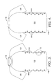
- FIG. 4 illustrates a back view of the outer-facing surface of the exemplary apparel item of FIG. 3 in accordance with aspects herein;
- FIG. 5 illustrates a close-up view of the outer-facing surface of the exemplary apparel item of FIG. 3 in accordance with aspects herein;
- FIG. 6 illustrates a close-up view of the inner-facing surface of the exemplary apparel item of FIG. 1 in accordance with aspects herein;
- FIG. 7A-7D illustrate cross-sectional views of an exemplary foam node undergoing a curing process in accordance with aspects herein;
- FIG. 8 illustrates a top-down view of an exemplary foam node in accordance with aspects herein;
- FIG. 9A illustrates an exemplary foam node on a first surface of a textile in accordance with aspects herein;
- FIG. 9B illustrates a second opposite surface of the textile of FIG. 9A in accordance with aspects herein;
- FIG. 10A illustrates an exemplary foam node on a first surface of a textile in accordance with aspects herein;
- FIG. 10B illustrates a second opposite surface of the textile of FIG. 9A in accordance with aspects herein;
- FIG. 11 illustrates an exploded view of an exemplary apparel system that utilizes foam nodes in accordance with aspects herein;
- FIG. 12 illustrates the exemplary apparel system of FIG. 11 in an as-assembled configuration in accordance with aspects herein;
- FIG. 13 illustrates a cross-sectional view of an exemplary perforated foam node in accordance with aspects herein;
- FIG. 14 illustrates a cross-sectional view of an exemplary foam node on a first surface of a base material that creates an emboss pattern and a deboss pattern on a second opposite surface of the base material in accordance with aspects herein;
- FIG. 15 illustrates a flow diagram of an exemplary method of manufacturing an apparel item having one or more foam nodes in accordance with aspects herein;
- FIGS. 16A-16H illustrate exemplary shapes for foam nodes in accordance with aspects herein.
- foam nodes or “foam ink nodes”
- the foam ink nodes may be used to create stand-off between an apparel item and a wearer's skin surface. This may be useful for reducing the perception of cling and for creating a space in which air can circulate to help cool the wearer by enhancing at least evaporative heat transfer.
- one or more of the foam nodes, or areas of the textile surrounding the foam nodes may be perforated to provide a fluid communication path between an inner-facing surface and an outer-facing surface of the apparel item. The communication path may be used to facilitate air exchange between the external environment and the wearer's body and/or to provide an exit path for moisture vapor generated by the wearer.
- the foam nodes described herein may also be used to create stand-off between, for instance, a first layer apparel item and a second layer apparel item configured to be worn over the first layer. Creating stand-off between these layers may provide an insulative effect as warmed air circulates in the space between the two layers.
- the creation of foam nodes on a first surface of the apparel item may create a deboss pattern and an optional emboss pattern on a second opposite surface of the apparel item.
- the deboss pattern (and the emboss pattern when present) may help to further increase the amount of stand-off associated with a particular node.
- the deboss patterns may be used to create channels or paths to, for instance, guide water or air traveling over the apparel item.
- directional terms such as anterior, posterior, superior, inferior, lateral, medial, upper, lower, front, back, and the like are to be given their common anatomical meaning and are used with respect to the apparel item being in an as-worn configuration by a wearer standing in anatomical position.
- terms such as coupling, affixing, securing, and the like may comprise releasably securing items together or permanently securing items together using affixing technologies known in the art such as stitching, bonding, adhesives, welding, buttons, snaps, zippers, hook-and-loop fasteners, and the like.
- foam node or “foam ink node” may be defined as a node formed by incorporating a foaming additive into one or more ink formulations (water-based, silicone-based, polyurethane-based, rubber-based, acrylic-based, plastisol inks, and the like).
- Exemplary ratios of the foaming additive (which may be pre-mixed) to the ink formulation may comprise 80:20, 70:30, 60:40, and/or 50:50 although ratios other than those listed are contemplated herein.
- the percentage of foaming additive, and/or the type of foaming additive may help to determine the amount of stand-off associated with a particular foam node.
- the percentage of foaming additive, and/or the type of foaming additive may be selected to achieve varying levels or degrees of emboss or deboss on the opposite surface of the foam node.
- the foaming additive/ink formulation may be applied or adhered to an apparel item utilizing, for instance, screen printing (using, for instance, a regular screen or a high-density screen), two-dimensional (2-D) printing, 3-D printing, manual application, and the like.
- screen printing using, for instance, a regular screen or a high-density screen
- two-dimensional (2-D) printing 3-D printing
- manual application and the like.
- an activator such as heat, light, radio-frequency waves, ultrasound, water, chemicals, and the like
- the foaming additive expands to form cells or microspheres within the base ink.
- the ink formulation “rises” or extends away from the surface plane of the apparel item in all directions (e.g., in an x-direction, a y-direction, and a z-direction) by a predetermined amount which may be dependent upon the particular foaming additive/ink formulation used and/or may be dependent upon the variables associated with the activation process such as time, temperature, intensity, and the like.
- the term “foam node” or “foam ink node” may encompass a single layer of the foaming additive/ink formulation or multiple layers of the foaming additive/ink formulation (2 layers, 3 layers, up to, for instance, 6 layers).
- each layer may be partially activated or cured (the terms “activated” and “cured” may be used interchangeably herein) before the addition of the new layer.
- the partial activation may help to at least partially set the ink (e.g., causing the ink to assume a gel-like consistency) and to initiate the expansion of the foaming additive.
- Partially setting the ink may help to prevent the ink from spreading on the base textile when a subsequent ink layer is applied.
- One exemplary process for partially setting the ink may comprise flash curing the ink layers by exposing the applied foaming additive/ink formulation to temperatures within a predetermined range for a predetermined amount of time. Once all the layers have been applied, the foam node may undergo a final activation or curing step that fully sets the ink and completes the activation of the foaming additive.
- the final curing step may comprise exposing the applied layers to a temperature that is higher than the temperature used to partially cure the foaming additive/ink formulation.
- each layer may comprise the same foaming additive/ink formulation, or different foaming additive/ink formulations may be used for one or more of the layers. It is further contemplated herein, that one or more of the layers may not comprise a foaming additive.
- a base or primer layer may be used to help seal the base textile and to help control the direction the foam node expands, where the base layer may not comprise a foaming additive.
- a top layer may be used to help seal the node and/or provide a soft feel since this layer may come into contact with a wearer's skin surface, where the top layer may not comprise a foaming additive.
- the top layer may also be configured to provide a cooling feature to the wearer when the layer comes into contact with the wearer's skin.
- the top layer may be impregnated with a cooling agent such as a menthol, peppermint, spearmint oil, and the like that may provide the perception of cooling when it comes into contact with a wearer's skin.
- a cooling agent such as a menthol, peppermint, spearmint oil, and the like that may provide the perception of cooling when it comes into contact with a wearer's skin.
- each layer may have the same thickness, or one or more of the layers may have a different thickness. Any and all aspects, and any variation thereof, are contemplated as being within the scope herein.
- an apparel item comprising at least one panel of material having an inner-facing surface and an outer-facing surface.
- the apparel item further comprises one or more foam ink nodes located on the inner-facing surface of the panel of material.
- a method of manufacturing an apparel item having one or more foam ink nodes may comprise providing at least a first panel of material having a first surface and a second opposite surface, applying at least a first layer of ink having a foaming additive in a first predetermined pattern to at least a portion of the first surface, activating or curing the ink, and forming the apparel item from at least the first panel such that the first surface of the first panel forms an inner-facing surface of the apparel item.
- a layered apparel system comprises an inner article having a first plurality of foam ink nodes located on at least one of an inner-facing surface or an outer-facing surface of the inner apparel item, and an outer article configured to be layered over the inner article.
- the outer article comprises a second plurality of foam ink nodes located on an inner-facing surface of the outer article.
- a further aspect provides for an apparel item comprising at least one panel of material comprising an inner-facing surface and an outer-facing surface, and at least one foam node applied to the inner-facing surface of the panel of material, where the foam node extends convexly away from the surface plane of the panel of material, and where on the outer-facing surface of the panel of material at a location corresponding to the foam node a deboss pattern is formed.
- FIGS. 1 and 2 a front view and a back view respectively of an inner-facing surface of an exemplary apparel item 100 are depicted in accordance with aspects herein.
- the apparel item 100 is shown “turned inside out.”
- the apparel item 100 may comprise a front panel 110 , a first sleeve portion 112 , and a second sleeve portion 114 .
- the apparel item 100 may further comprise a back panel 210 that together with the front panel 110 help to define at least a neckline opening 116 , a waist opening 118 and right and left sleeve openings (not shown) to which the sleeve portions 112 and 114 extend.
- front panel and back panel are used, it is contemplated herein that the front panel 110 and the back panel 210 (and optionally the sleeve portions 112 , 114 ) may comprise a unitary panel formed through, for instance, a knitting and/or weaving process and assembled to form the apparel item 100 .
- one or more additional panels e.g., side panels, additional front panels, additional back panels, shoulder panels
- the apparel item may take the form of a sleeveless shirt, a long sleeve shirt, a jacket, a short, a pant, a sock, a hat, and the like. Any and all aspects, and any variation thereof, are contemplated as being within the scope herein.
- the material used to form the front panel 110 , the back panel 210 , and/or the sleeve portions 112 and 114 may comprise a knitted, woven, or non-woven lightweight fabric.
- Exemplary weights for the fabric may comprise less than 300 grams per square meter (gsm), less than 250 gsm, less than 200 gsm, less than 150 gsm, less than 140 gsm, and/or less than 130 gsm, although weights above, below, and between these values are contemplated herein.
- the material may have a degree of elasticity (two-way stretch and/or four-way stretch) imparted by using elastic yarns or fibers such as spandex, elastane, lycra, and the like.
- the material in exemplary aspects, may further exhibit moisture-management characteristics (i.e., the ability of a fabric to move moisture from a first face of the fabric to a second opposite face of the fabric), and/or other characteristics such as enhanced air permeability, resistance to water, and the like. Any and all aspects, and any variation thereof, are contemplated as being within the scope herein.
- one or more foam nodes 120 may be applied to the inner-facing surface of the front panel 110 such that they extend convexly away from the inner-facing surface of the front panel 110 (i.e., in a z-direction toward a body surface of a wearer when the apparel item 100 is worn).
- Application may be by, for instance, screen-printing, 2-D printing, 3-D printing, manual application, and the like.
- FIG. 1 shows that the inner-facing surface of the front panel 110 may be applied to the inner-facing surface of the front panel 110 such that they extend convexly away from the inner-facing surface of the front panel 110 (i.e., in a z-direction toward a body surface of a wearer when the apparel item 100 is worn).
- Application may be by, for instance, screen-printing, 2-D printing, 3-D printing, manual application, and the like.
- the foam nodes 120 may also be applied to the inner-facing surface of the back panel 210 such that they extend convexly away from the inner-facing surface of the back panel 210 (i.e., in a z-direction toward the body surface of a wearer when the apparel item 100 is worn).
- the foams nodes 120 may be positioned on the apparel item 100 based on cling or contact maps (maps indicating parts of the body that come into contact with a loose-fitting garment averaged over several athletic positions). However, it is further contemplated herein that the foam nodes 120 may be positioned on the apparel item 100 based on, for example, skin temperature maps, sweat maps, air pressure maps, and the like
- the foam nodes 120 may be positioned along the sides of the apparel item 100 from a location generally inferior to the sleeve openings for the first and second sleeve portions 112 and 114 to an area generally near the bottom edge of the apparel item 100 (i.e., within 5 cm to 40 cm of the bottom edge of the apparel item 100 ).
- This area is typically associated with moderate to high amounts of cling or contact between the apparel item 100 and the wearer's body surface.
- Other areas known to have moderate to high cling may comprise for instance the superior region of the front panel 110 and/or the superior region of the back panel 210 .
- the foam nodes 120 may be positioned along an anterior aspect of the leg portions of the pant such that they are positioned adjacent to the quadriceps muscle group of the wearer when the pant is worn, and they may be positioned along a posterior aspect of the leg portions of the pant such that they are positioned adjacent to the calf muscles of the wearer. Any and all aspects, and any variation thereof, are contemplated as being within aspects herein. By providing stand-off in these areas, the perception of cling may be reduced thereby improving wearer comfort.
- the foam nodes 120 may also be positioned at areas of the apparel item 100 that correspond to moderate to high sweat-producing areas of the wearer.
- the nodes 120 may be positioned at the superior, central region of the front panel 110 and/or the superior, central region of the back panel 210 (areas corresponding to the upper chest area and upper back area of the wearer when the apparel item 100 is worn). By providing stand-off in these areas, air may circulate in the space between the inner-facing surface of the apparel item 100 and the wearer's skin surface and thus promote evaporative cooling.
- some or all of the nodes 120 may be perforated to form a fluid communication path from the inner-facing surface of the apparel item 100 to the outer-facing surface of the apparel item 100 .
- the perforations may provide an exit point for moisture vapor produced by the wearer to exit the apparel item 100 and/or may provide an ingress path for air from the external environment to enter the apparel item 100 .
- the depiction of the location, size, pattern, and orientation of the foam nodes 120 in FIGS. 1 and 2 are exemplary only, and it is contemplated herein that other locations, sizes, patterns, and orientations for the nodes 120 may be within the scope of this disclosure.
- the nodes 120 may be located on the sleeve portions 112 and 113 as well as the other locations described above.
- the nodes 120 are generally depicted relatively large in size for illustrative purposes. Exemplary dimensions for the nodes 120 may vary depending on the particular pattern associated with each node, but in general each node may range from 0.5 cm to 4 cm in length and from 0.5 cm to 2 cm in width. As will be explained in greater depth below with respect to FIG. 7 , exemplary heights of the nodes 120 may comprise between 1 mm up to 6 mm. Any and all aspects, and any variation thereof, are contemplated as being within the scope herein.
- FIG. 6 a close-up view of a portion of the foam nodes 120 taken at the area indicated on FIG. 1 is provided in accordance with aspects herein.
- the foam nodes 120 are depicted as having multiple layers, although it is contemplated herein that one or more of the nodes 120 may comprise a single layer or just two layers.
- a first layer 610 is shown as well as a second layer 612 , and a third layer 614 .
- the first layer 610 occupies a greater surface area than the second layer 612
- the second layer 612 occupies a greater surface area than the third layer 614 .
- the third layer 614 which is the top layer of the node 605 , may comprise the smallest surface area as this layer may be configured to be in contact with the wearer's skin when the apparel item 100 is worn.
- the deboss pattern produced by the respective node may be sculpted to have a shape generally matching that of the respective node (e.g., a greater depth of the deboss pattern in areas corresponding to the third layer 614 , and a lesser depth of the deboss pattern in areas corresponding to the first or second layers 610 or 612 ).
- the ink formulation for the third layer 614 may be selected to have a soft feel or hand as this layer may be adjacent to a skin surface of the wearer when the apparel item 100 is worn.
- a silicone-based ink formulation may be selected as these formulations generally have a soft feel and exhibit a degree of elasticity that allows them to stretch without cracking or breaking.
- Ink formulations that are considered to be hypoallergenic may also be selected to reduce the chances of skin irritation.
- different finishes may be applied to the third layer 614 to further increase the soft feel and/or comfort of the third layer 614 . Examples include flocking, creating a “suede-type” finish using one or more additives, and the like.
- an additive such as glass beads, may be added to the ink formulation for the third layer 614 to create a slick or smooth surface.
- one or more of the nodes 120 may be perforated.
- the node indicated by the reference numeral 616 comprises a perforation 618 that extends through the node 616 and the underlying base material of the apparel item 100 .
- the perforation 618 forms a fluid communication path from the inner-facing surface of the apparel item 100 to the outer-facing surface of the apparel item 100 .
- the perforation 618 may be formed by a mechanical process, laser cutting, water-jet cutting, ultrasonic cutting, and the like. Although only one perforation is shown, it is contemplated herein that multiple perforations may extend through the node 616 and the underlying base material of the apparel item 100 .
- the location of the perforation 618 on the node 616 may be selected based on the shape configuration of the node 616 . For instance, and as will be more fully explained below, the perforation 618 may be located near the trailing edge of the node 616 (the edge of the node 616 that is further away from the vertical midline of the front panel 110 ). By positioning the perforation 618 in this location, air traveling over the front of the apparel item 100 may be channeled toward and into the perforation 618 to optimize air flowing into the apparel item 100 .
- the perforation 618 may be located at other areas of the node 616 (e.g., at a leading edge, midway between the leading edge and the trailing edge, and the like). Any and all aspects, and any variation thereof, are contemplated as being within aspects herein.
- perforations may also be formed in one or more areas adjacent to the node 616 .
- perforations may extend through the base textile surrounding the node 616 .
- FIG. 8 depicts a top view of an exemplary foam node structure 805 printed on a base material 800 .
- the foam node structure 805 comprises a primer layer 810 which, in exemplary aspects, may comprise a clear silicone base.
- the primer layer 810 may not contain a foaming additive.
- the primer layer 810 may be applied to the base material 800 (via, for instance, a screen printing process, a 2-D printing process, a 3-D printing process, a manual application, and the like), and may help to reinforce or seal the base material 800 in areas where foam nodes are located.
- the foam node structure 805 further comprises a plurality of foam elements 812 , 814 , 816 , 818 , and 822 printed on to the primer layer 810 .
- perforations such as perforations 820 , 824 and 826 may be formed through just the primer layer 810 of the foam node structure 805 .
- additional perforations may be formed through one or more of the foam elements 812 , 814 , 816 , 818 , or 822 .
- the perforations 820 , 824 , and 826 are less likely to tear or extend beyond their original boundaries thereby helping to maintain the structural integrity of the base material 800 .
- the pattern associated with the foam node structure 805 is exemplary only, and it is contemplated herein that other patterns for the primer layer and/or the foam elements are within the scope of the disclosure.
- FIGS. 3 and 4 front and back views respectively of an outer-facing surface of the apparel item 100 are depicted in accordance with aspects herein.
- the outer-facing surface of the apparel item 100 may comprise debossed regions 320 that correspond to the underlying foam nodes 120 .
- a depiction of how the debossed regions 320 are formed is illustrated in FIGS. 7A-7D .
- FIG. 7A illustrates a cross-sectional view of a base material 700 having an inner-facing surface 710 and an outer-facing surface 712 in accordance with aspects herein.
- the base material 700 may, in exemplary aspects, have a weight between 130 gsm and 300 gsm (i.e., may be formed of a lightweight material).
- the base material 700 may also have a degree of elasticity such that its modulus of elasticity is above a threshold value.
- a first layer 714 of ink having a foaming additive is printed on to the inner-facing surface 710 of the base material 700 .
- a partial-curing step (e.g., a flash-curing step) is then carried out as indicated by the arrow to help set the ink and to begin activation of the foaming additive.
- FIG. 7B illustrates the base material 700 after the initial curing step.
- the first layer 714 has expanded in all directions (e.g., in an x-direction, a y-direction, and a z-direction) due to activation of the foaming additive by the heat as indicated by the arrows in FIG. 7B .
- the first layer 714 extends convexly away from the inner-facing surface 710 .
- the layer 714 is adhered to the underlying base material 700 , as the layer 714 expands in all directions, it may “lift” the underlying base material 700 . This may be possible due to the lightweight and elastic nature of the material. The result is that the base material 700 “puckers” to form a debossed region 716 on the outer-facing surface 712 of the base material 700 . As shown, the debossed region 716 extends concavely away from the outer-facing surface 712 of the base material 700 .
- the specific formulation of the ink and/or foaming additive, parameters associated with the curing or activation process, as well as the application pattern may be selected to achieve this deboss effect.
- FIG. 7C illustrates the base material 700 at a point when a second layer 718 of ink having a foaming additive (which may be the same formulation or a different formulation than the first layer 714 ) is printed on to the surface of the first layer 714 of partially cured ink.
- a second partial-curing step (e.g., a flash-curing step) is then carried out as indicated by the arrow.
- FIG. 7D illustrates the base material 700 after the second curing step.
- the second layer 718 has expanded in all directions (as indicated by the arrows) due to the activation of the foaming additive by the heat.
- the activation of the second layer 718 may cause further lifting or puckering of the underlying base material 700 to increase the amount of offset associated with the debossed region 716 .
- a minimum depth for the debossed region 716 may comprise between 0.5 mm and 1.0 mm.
- the degree of puckering or degree of deboss of the base material 700 may be more pronounced in areas corresponding to the second layer 718 .
- the shape of the deboss pattern may be sculpted or modified so that greater deboss is achieved in areas corresponding to multiple layers of ink/foaming additive and lesser deboss is achieved in areas corresponding to single layers of the ink/foaming additive formulation.
- a final curing step may be carried out to set the ink and to optionally complete activation of the foaming additive.
- the height of the debossed region 716 when combined with the height of the first and second layers 714 and 718 (and/or optional additional layers) may create a total stand-off height for the resulting node of between 1.5 mm to 6 mm, between 3 mm to 5 mm, or between 3 mm to 4 mm as indicated by the reference numeral 722 . It is contemplated herein that additional layers of ink with a foaming additive may be added, while balancing comfort to the wearer, to further increase the stand-off height of the resulting node.
- the shape, pattern, and location of the debossed regions 320 correspond to the shape, pattern, and location of the underlying foam nodes 120 . This is shown more clearly in FIG. 5 which depicts a close-up view of the debossed regions 320 taken at the area indicated on FIG. 3 .
- the debossed regions 320 comprise indentations or offsets in the fabric forming the outer-facing surface of the apparel item 100 .
- the debossed regions 320 project concavely inward from the outer-facing surface of the apparel item 100 (i.e., toward a body surface of a wearer when the apparel item 100 is in an as-worn configuration).
- the debossed regions 320 have a shape and location corresponding to the shape and location of the underlying foam nodes 120 (shown in FIG. 6 ).
- the perforation 618 (also shown in FIG. 6 ) is depicted as extending through the debossed region 320 to form a communication path from the outer-facing surface to the inner-facing surface of the apparel item 100 .
- FIG. 9A illustrates a perspective view of a first surface of a base material 900 having a foam node 910 printed thereon.
- the foam node 910 comprises a series of foam arms 912 that radially extend away from a central area 914 , where the central area 914 does not have any foam ink printed thereon.
- the emboss/deboss effect achieved by this pattern can be seen in FIG.
- FIG. 9B which illustrates a second opposite-facing surface of the base material 900 .
- the foam arms 912 have created a corresponding set of debossed channels 916 on the second surface of the base material 900 .
- An embossed region 918 is created at the center of the debossed channels 916 , where the embossed region 918 corresponds to the central area 914 between the foam arms 912 of the foam node 910 . As shown, the embossed region 918 extends convexly away from the second surface.
- the embossed region 918 may be created due to a radial puckering or “drawing-in” of the surrounding fabric by the foam arms 912 causing the material at the embossed region 918 to be pushed outwardly away from the surface plane of the base material 900 .
- a minimum height of the embossed region 918 may comprise between 0.5 mm and 1.0 mm.
- FIGS. 10A and 10B illustrate another emboss/deboss pattern created by utilizing a particular configuration for the foam node.
- FIG. 10A depicts a first surface of a base material 1000 having a foam node 1010 printed thereon.
- the foam node 1010 comprises a plurality of separate elements including at least a triangular element 1012 and two leg elements 1014 . Areas of the base material 1000 between the triangular element 1012 and the leg elements 1014 , and between the two leg elements 1014 do not have any foam ink material printed thereon.
- FIG. 10B which illustrates a second opposite-facing surface of the base material 1000 . As shown in FIG.
- the triangular element 1012 and the two leg elements 1014 have created corresponding deboss regions 1016 and 1018 respectively.
- the deboss regions 1018 in particular, form channels or paths on the base material 1000 .
- Embossed regions 1020 and 1022 are created between the deboss region 1016 and 1018 , and between the two debossed regions 1018 respectively.
- a corresponding deboss pattern is formed on the opposite surface.
- both a deboss pattern and an emboss pattern may be formed on the opposite surface where the deboss pattern corresponds to the separate foam elements, and the emboss pattern is formed in the spaces between the separate foam elements. It is contemplated herein, that any number of foam nodes patterns may be formed on the base material with a corresponding number of deboss/emboss patterns formed on the second opposite surface.
- foam nodes having a shape similar to the foam nodes 120 may be formed over the majority of the inner-facing surface of, for example, the front panel 110 of the apparel item 100 .
- Corresponding debossed regions 320 would be formed on the outer-facing surface of the apparel item 100 (similar to the dimples formed on a golf ball).
- the debossed regions 320 When air flows over the front panel 110 (due to, for instance, a running action by the wearer), the debossed regions 320 would create a degree of turbulence in the air. As the air travel around the sides and shoulders of the apparel item 100 , the turbulence may help the flowing air to conform more closely to the wearer creating a smaller vortex and less drag.
- FIG. 13 depicts a cross-sectional view of a portion of a base material 1300 of an apparel item, such as the apparel item 100 , being worn by a wearer.
- the inner-facing surface of the base material 1300 is indicated by the reference numeral 1312
- the outer-facing surface of the base material 1300 is indicated by the reference numeral 1310
- the skin surface of the wearer is indicated by the reference numeral 1314 .
- a foam node 1319 having a first layer 1316 and a second layer 1318 is printed on to the inner-facing surface 1312 of the base material 1300 such that it is generally in contact with the wearer's skin surface 1314 when the apparel item is worn.
- a corresponding debossed region 1313 is formed on the outer-facing surface 1310 of the base material 1300 .
- a perforation 1320 is formed through the first and second layers 1316 and 1318 as well as the base material 1300 .
- the node 1319 is positioned such that its long axis lies along a generally horizontal plane of the apparel item when the apparel item is worn, and the perforation 1320 is positioned at the rear of the node 1319 . To put it another way, the perforation 1320 is positioned at a trailing edge of the node 1319 . Air flow is indicated by the arrow 1322 and is shown traveling generally from the front (indicated) to the rear (indicated) of the apparel item.
- the debossed region 1313 may help to capture and funnel the air flow 1322 such that it enters the perforation 1320 and circulates in the space between the inner-facing surface 1312 of the base material 1300 and the wearer's skin surface 1314 where it may help to cool the wearer by promoting evaporative heat transfer.
- FIG. 14 depicts a cross-sectional view of a base material 1400 having a foam node printed thereon similar to that shown in FIG. 9A .
- the base material 1400 comprises a first surface 1410 and a second opposite surface 1412 .
- Two foam arms 1414 are shown printed on the second surface 1412 .
- Reference numeral 1416 indicates a central area on the second surface 1412 that does not have foam ink material printed thereon, where the central area 1416 is located between the foam arms 1414 .
- debossed regions 1418 are created that correspond to the foam arms 1414 , and an embossed region 1420 is formed that corresponds to the central area 1416 .
- a height 1422 taken from top of the embossed region 1420 to the lowermost point of the foam arms 1414 is greater than a height 1424 taken from the surface plane of the base material 1400 to the lowermost point of the foam arms 1414 .
- greater stand-off may be achieved by utilizing a foam node pattern that creates debossed regions as well as embossed regions.
- a perforation may be formed through the embossed region 1420 to help channel air into and out of the base material 1400 .
- This may be advantageous when the embossed region 1420 is formed on the outer-facing surface of the base material 1400 such that the embossed region 1420 represents an area of the apparel item that projects furthest away from the surface plane of the base material 1400 .
- the embossed region 1420 may be positioned such that it is better exposed to air traveling over the base material 1400 , and air may enter the base material 1400 via the perforation. Any and all aspects, and any variation thereof, are contemplated as being within the scope herein.
- foam node having elements that create debossed channels or paths on the opposite surface may be used to create channel or paths on the opposite surface of the base textile (such as the debossed regions 1018 in FIG. 10B ). These channels or paths may be used to guide air flowing over the apparel item (e.g., guide air to one or more perforations or vent openings), and or to guide water flowing over the apparel item (e.g., guide rain or precipitation to shed points using the channels). It is contemplated that any number of foam node patterns may be used on a single apparel item to achieve some of the functional benefits described above: creating stand-off, guiding air flow, guiding water flow, promoting breathability, and the like.
- FIGS. 16A-16H illustrate some additional exemplary foam node shapes in accordance with aspects herein.
- the nodes depicted in FIGS. 16A-16H may comprise a single layer or multiple layers of ink. Moreover, the nodes may comprise an optional primer layer.
- FIG. 16A depicts a node 1600 having an elongate oval shape. In exemplary aspects, the node 1600 may have a length between, for example, 10 mm and 40 mm and have a stand-off height between, for example, 2.5 mm and 7.5 mm.
- FIG. 16B depicts a node 1610 have a circular shape.
- the node 1610 may have a diameter between 4.5 mm and 30 mm and have a stand-off height between 2.5 mm and 7.5 mm.
- FIG. 16C depicts a node 1620 having an ellipsoid shape.
- the long axis of the node 1620 may have a length between 10 mm and 35 mm, and the node 1620 may have a stand-off height between, for instance, 2.5 mm and 7.5 mm.
- FIG. 16D depicts a node 1630 having a generally quatrefoil shape.
- the node 1630 may have a length between, for example, 5.5. mm and 12.5 mm and have a stand-off height between, for instance, 2.5 mm and 6.5 mm.
- FIGS. 16E-16H depict exemplary shapes for nodes comprising areas with foam ink and areas without foam ink.
- FIG. 16 depicts a node 1640 with a quatrefoil shape comprising areas 1642 with foam ink and areas 1644 without foam ink.
- the node 1640 may have a length between 5.5 mm and 12.5 mm and a stand-off height between 2.5 mm and 6.5 mm.
- FIG. 16F depicts a node 1650 with an elongated oval shape.
- the node 1650 may have a length between, for example, 34 mm and 36 mm and have a stand-off height between 2.5 mm and 7.5 mm.
- FIG. 16G depicts a node 1660 comprising an ellipsoid shape.
- the length, as measured along the long axis of the node 1660 may be between 34 mm and 36 mm, and the node 1660 may have a stand-off height between 2.5 mm and 7.5 mm.
- FIG. 16H depicts a node 1670 having a circular shape.
- the node 1670 may have a diameter between 4.5 mm and 30 mm and have a stand-off height between 2.5 mm and 6.5 mm. Any and all aspects, and any variation thereof, are contemplated as being within aspects herein.
- an apparel system that utilizes printed foam nodes to create stand-off between, for instance, a base layer and a wearer's skin surface, between the base layer and an overlying layer, between a mid-layer and an outer layer, and the like.
- FIGS. 11-12 depict an exploded view of an exemplary apparel system 1100 that utilizes printed foam nodes in accordance with aspects herein.
- the system 1100 is comprised of a base layer inner article 1110 and an outer article 1112 .
- the base layer inner article 1110 may comprise at least a front panel 1118 , and a back panel (not shown) that help to define in part at least a neckline opening, a waist opening, and first and second sleeve openings.
- the base layer inner article 1110 may further optionally comprise a first sleeve portion 1114 and a second sleeve portion 1116 .
- the base layer inner article 1110 may be in the form of a pant, shorts, a glove, a sock, a hat, and the like.
- the base layer inner article 1110 may be formed from a material that is acceptable for skin contact.
- the base layer inner article 1110 may be formed from a lightweight knit or woven material.
- the base layer inner article 1110 may exhibit moisture-management characteristics.
- the outer article 1112 is contemplated as being worn over the base layer inner article 1110 when in an assembled configuration.
- the outer article 1112 may be unaffixed to the base layer inner article 1110 prior to being donned.
- the outer article 1112 may be affixed to the base layer inner article 1110 in one or more locations.
- the outer article 1112 may comprise at least a front panel 1124 , and a back panel (not shown) that together with the front panel help to define at least in part a neckline opening, a waist opening, and first and second sleeve openings.
- the outer article 1112 may further optionally comprise a first sleeve portion 1120 and a second sleeve portion 1122 .
- the outer article 1112 corresponds in shape to the base layer inner article 1110 .
- the base layer inner article 1110 is configured as a pant, shorts, a glove, a sock, or a hat, the outer article 1112 would assume a similar configuration.
- the outer article 1112 may be formed of a material suitable for this type of contact.
- the outer article 1112 may comprise a knitted or woven material having a heavier weight and/or greater durability than the base layer inner article 1110 (although, in exemplary aspects, the outer article 1112 may still have a weight less than 300 gsm).
- the outer article 1112 in exemplary aspects, may be treated with a durable water repellant (DWR) finish.
- DWR durable water repellant
- the depiction of the base layer inner article 1110 and the outer article 1112 in FIGS. 11 and 12 focuses on the use of foam nodes to provide offset between, for instance, the base layer inner article 1110 and the wearer's skin and/or between the outer article 1112 and the base layer inner article 1110 .
- the debossed/embossed features described above are not shown in FIGS. 11 and 12 although it is contemplated herein that each of the articles 1110 and 1112 may include the emboss/deboss features described above to provide the functional benefits described above.
- the article 1110 may comprise a set of foam nodes 1126 located on the inner-facing surface of the base layer inner article 1110 (as indicated by the dashed lines in FIG. 11 ).
- the foam nodes 1126 may provide stand-off between the inner-facing surface of the base layer inner article 1110 and the wearer's skin surface. The stand-off may help to reduce the perception of cling as well as provide a space in which air can circulate to help cool the wearer by promoting, for instance, evaporative heat transfer.
- some or all of the nodes 1126 may comprise perforations to provide a communication path from the inner-facing surface to the outer-facing surface of the base layer inner article 1110 . This, in turn, may help promote breathability of the base layer inner article 1110 .
- the size and placement of the foam nodes 1126 is illustrative and exemplary only, and it contemplated herein, that the nodes 1126 may be different sizes or be located in other areas of the base layer inner article 1110 (e.g., the back, the sleeves, and/or front middle of the article 1110 ). Any and all aspects, and any variation thereof, are contemplated as being within the scope herein.
- the base layer inner article 1110 may optionally further comprise foam nodes 1130 located on the outer-facing surface of the article 1110 .
- the nodes 1130 may have a different shape configuration or the same shape configuration as the foam nodes 1126 .
- the foam nodes 1130 may be used to provide stand-off between the base layer inner article 1110 and the outer article 1112 as will be explained in greater depth below. Some or all of the foam nodes 1130 may comprise perforations extending therethrough.
- the location and size of the foam nodes 1130 is exemplary only, and it is contemplated herein, that the foam nodes 1130 may be located in other areas (e.g., the sides, sleeve portions, and/or back of the base layer inner article 1110 ) and/or be different sizes and shapes. Any and all aspects, and any variation thereof, are contemplated as being within the scope herein.
- the outer article 1112 may further comprise foam nodes 1128 located on the inner-facing surface of the outer article 1112 (as indicated by the dashed lines).
- the foam nodes 1128 may produce stand-off from the base layer inner article 1110 .
- the foam nodes 1128 alone, or in combination with the optional foam nodes 1130 may help to create a space between the outer-facing surface of the base layer inner article 1110 and the inner-facing surface of the outer article 1112 . Air that has been warmed by the wearer may circulate in this space to provide an insulative effect.
- one or more of the foam nodes 1128 may be perforated to provide an egress point for moisture vapor to exit the apparel system 1100 and/or an ingress point for ambient air to enter the space between the outer article 1112 and the base layer inner article 1110 .
- the location and size of the foam nodes 1128 is exemplary only, and it is contemplated herein, that the foam nodes 1128 may be located in other areas (e.g., the sides, sleeve portions, upper front, and/or back of the outer article 1112 ) and/or be different sizes and shapes. Any and all aspects, and any variation thereof, are contemplated as being within the scope herein.
- the location and/or pattern of the foam nodes 1128 located on the outer article 1112 may be complementary to the location and/or pattern of the foam nodes 1126 and optionally the foam nodes 1130 located on the base layer inner article 1110 .
- the respective nodes 1126 , 1128 , and/or 1130 may be positioned such that they do not directly contact each other when the apparel system 1100 is worn.
- FIG. 12 depicts the outer article 1112 positioned over the base layer inner article 1110 (shown by the dashed lines). As shown, the nodes 1126 , 1128 , and 1130 are positioned on the respective articles such that they do not directly contact each other.
- the nodes By configuring the nodes as such, a greater percentage of stand-off over the apparel system 1100 may be achieved without utilizing an increased number of foam nodes. This, in turn, may help keep manufacturing costs down and also improve wearer comfort. However, it is contemplated herein that there may be examples where foam nodes located on either the base layer inner article 1110 or the outer article 1112 may contact or partially contact one another. Further, it is contemplated herein, that the amount of stand-off associated with the foam nodes 1126 and 1130 may be the same, less than, or greater than the amount of stand-off associated with the nodes 1128 .
- foam nodes may be located just on the inner-facing surface of the outer article 1112 (and not on the base layer inner article 1110 ), or on just the outer-facing surface of the base layer inner article 1110 to provide stand-off between the base layer inner article 1110 and the outer article 1112 . Any and all aspects, and any variation thereof, are contemplated as being within the scope herein.
- a flow diagram of an exemplary method 1500 of manufacturing an apparel item, such as the apparel item 100 , having one or more printed foam ink nodes is illustrated in accordance with aspects herein.
- a first panel of material is provided, where the first panel of material has a first surface and a second surface opposite of the first surface.
- the first panel of material may be comprise a knitted or woven material having a weight less than or equal to, for instance, 300 gsm and having a modulus of elasticity above a predefined threshold.
- At a step 1512 at least a first layer of ink having a foaming additive is printed on or applied to at least a portion of the first surface of the panel of material, where the first layer of ink is applied in a predetermined pattern.
- the ink may be applied by utilizing a screen printing process, a 2-D printing process, a 3-D printing process, manual application, and the like.
- an optional primer layer may be applied to the first surface, where the primer layer may comprise a clear silicone-based layer with or without a foaming additive. When used, the primer layer may be partially cured before the method 1500 continues.
- the first layer of ink is partially cured to help activate the foaming additive and to help at least partially set the ink formulation.
- the method 1500 may further comprise applying one or more additional layers of ink/foaming additive formulations on top of the first layer, where each layer is partially cured before application of the next layer.
- Each of the layers, including the primer layer when used, may be applied in a different pattern or the same pattern as the preceding layer. Further, each of the layers may occupy a smaller surface area than the preceding layer such that the top layer occupies the smallest surface area compared to the other layers.
- the partial-curing step may comprise exposing the ink/foaming additive formulation to a predefined temperature for a predefined period of time.
- an optional top layer that may or may not have a foaming additive may be applied to help seal the resulting foam node and/or to impart a soft feel or texture to the node since the top layer may be in contact with a wearer's skin surface.
- the top layer may be impregnated with a cooling agent such as, for example, a menthol, spearmint, or peppermint oil that may provide a perception of cooling when it comes into contact with a wearer's skin.
- a final curing step may be done to fully set the node and to complete the activation of the foaming additive.
- the final curing step may be at a different temperature and time period than the partial curing steps (e.g., at a higher temperature and for a longer period of time).
- the partial-curing steps and the final curing step may be achieved using modalities such as infra-red light, ultrasound, radio-frequency waves, chemicals, water, ultra-violet lights, and the like. Any and all aspects, and any variation thereof, are contemplated as being within the scope herein.
- the apparel item is formed using at least the first panel such that when incorporated into the apparel item, the first surface of the panel forms an inner-facing surface of the apparel item.
- the apparel item may be initially formed and the foam nodes applied in a post-processing step.
- the method 1500 may further comprise perforating the foam node via, for instance, a mechanical process, laser cutting, water-jet cutting, ultrasonic cutting, and the like. The steps outlined above for the method 1500 may occur in any order.
- the foam node may be applied to the first panel after the first panel has been incorporated into the apparel item.
- the foam node may be perforated before or after the first panel has been incorporated into the apparel item. Any and all aspects, and any variation thereof, are contemplated as being within the scope herein.
Abstract
Aspects herein relate to apparel items and apparel systems that utilize applied or printed foam nodes to provide, among other things, stand-off between an apparel item and a wearer's skin surface. One or more of the foam nodes, or areas of the textile surrounding the foam nodes, may be perforated to provide a fluid communication path between an inner-facing surface and an outer-facing surface of the apparel item. The communication path may be used to facilitate air exchange between the external environment and the wearer's body and/or to provide an exit path for moisture vapor generated by the wearer.
Description
This application, entitled “Foam Nodes for Creating Stand Off on Apparel Items,” claims priority to U.S. Prov. App. No. 62/313,316, entitled “Foam Nodes for Creating Stand Off on Apparel Items,” and filed Mar. 25, 2016. The entirety of the aforementioned application is incorporated by reference herein.
Aspects herein relate to creating stand-off on apparel items using foam nodes.
Creating a space between an inner-facing surface of an apparel item and a wearer's body surface may be important to promote evaporative cooling and/or to reduce the perception of cling. Traditional athletic apparel often lacks any type of stand-off. When stand-off is present, current methods of creating stand-off may be labor intensive and expensive.
Examples of the present invention are described in detail below with reference to the attached drawing figures, wherein:
The subject matter of the present invention is described with specificity herein to meet statutory requirements. However, the description itself is not intended to limit the scope of this disclosure. Rather, the inventors have contemplated that the disclosed or claimed subject matter might also be embodied in other ways, to include different steps or combinations of steps similar to the ones described in this document, in conjunction with other present or future technologies. Moreover, although the terms “step” and/or “block” might be used herein to connote different elements of methods employed, the terms should not be interpreted as implying any particular order among or between various steps herein disclosed unless and except when the order of individual steps is explicitly stated.
Aspects herein relate to apparel items and apparel systems that utilize applied or printed foam nodes (hereinafter known as “foam nodes” or “foam ink nodes”) to provide stand-off as well as other functional benefits. In exemplary aspects, the foam ink nodes may be used to create stand-off between an apparel item and a wearer's skin surface. This may be useful for reducing the perception of cling and for creating a space in which air can circulate to help cool the wearer by enhancing at least evaporative heat transfer. In exemplary aspects, one or more of the foam nodes, or areas of the textile surrounding the foam nodes, may be perforated to provide a fluid communication path between an inner-facing surface and an outer-facing surface of the apparel item. The communication path may be used to facilitate air exchange between the external environment and the wearer's body and/or to provide an exit path for moisture vapor generated by the wearer.
The foam nodes described herein may also be used to create stand-off between, for instance, a first layer apparel item and a second layer apparel item configured to be worn over the first layer. Creating stand-off between these layers may provide an insulative effect as warmed air circulates in the space between the two layers.
Moreover, the creation of foam nodes on a first surface of the apparel item may create a deboss pattern and an optional emboss pattern on a second opposite surface of the apparel item. The deboss pattern (and the emboss pattern when present) may help to further increase the amount of stand-off associated with a particular node. As well, the deboss patterns may be used to create channels or paths to, for instance, guide water or air traveling over the apparel item.
As used throughout this disclosure, directional terms such as anterior, posterior, superior, inferior, lateral, medial, upper, lower, front, back, and the like are to be given their common anatomical meaning and are used with respect to the apparel item being in an as-worn configuration by a wearer standing in anatomical position. Moreover, unless indicated otherwise, terms such as coupling, affixing, securing, and the like may comprise releasably securing items together or permanently securing items together using affixing technologies known in the art such as stitching, bonding, adhesives, welding, buttons, snaps, zippers, hook-and-loop fasteners, and the like.
Continuing, as used throughout this disclosure, the term “foam node” or “foam ink node” may be defined as a node formed by incorporating a foaming additive into one or more ink formulations (water-based, silicone-based, polyurethane-based, rubber-based, acrylic-based, plastisol inks, and the like). Exemplary ratios of the foaming additive (which may be pre-mixed) to the ink formulation may comprise 80:20, 70:30, 60:40, and/or 50:50 although ratios other than those listed are contemplated herein. The percentage of foaming additive, and/or the type of foaming additive, may help to determine the amount of stand-off associated with a particular foam node. As well, the percentage of foaming additive, and/or the type of foaming additive, may be selected to achieve varying levels or degrees of emboss or deboss on the opposite surface of the foam node.
The foaming additive/ink formulation may be applied or adhered to an apparel item utilizing, for instance, screen printing (using, for instance, a regular screen or a high-density screen), two-dimensional (2-D) printing, 3-D printing, manual application, and the like. Upon exposure to an activator such as heat, light, radio-frequency waves, ultrasound, water, chemicals, and the like, the foaming additive expands to form cells or microspheres within the base ink. The result is that the ink formulation “rises” or extends away from the surface plane of the apparel item in all directions (e.g., in an x-direction, a y-direction, and a z-direction) by a predetermined amount which may be dependent upon the particular foaming additive/ink formulation used and/or may be dependent upon the variables associated with the activation process such as time, temperature, intensity, and the like.
Further, it is contemplated herein that the term “foam node” or “foam ink node” may encompass a single layer of the foaming additive/ink formulation or multiple layers of the foaming additive/ink formulation (2 layers, 3 layers, up to, for instance, 6 layers). With this aspect, each layer may be partially activated or cured (the terms “activated” and “cured” may be used interchangeably herein) before the addition of the new layer. In exemplary aspects, the partial activation may help to at least partially set the ink (e.g., causing the ink to assume a gel-like consistency) and to initiate the expansion of the foaming additive. Partially setting the ink, in turn, may help to prevent the ink from spreading on the base textile when a subsequent ink layer is applied. One exemplary process for partially setting the ink may comprise flash curing the ink layers by exposing the applied foaming additive/ink formulation to temperatures within a predetermined range for a predetermined amount of time. Once all the layers have been applied, the foam node may undergo a final activation or curing step that fully sets the ink and completes the activation of the foaming additive. In exemplary aspects, the final curing step may comprise exposing the applied layers to a temperature that is higher than the temperature used to partially cure the foaming additive/ink formulation.
When the foam node comprises multiple layers, it is contemplated herein that each layer may comprise the same foaming additive/ink formulation, or different foaming additive/ink formulations may be used for one or more of the layers. It is further contemplated herein, that one or more of the layers may not comprise a foaming additive. For instance, a base or primer layer may be used to help seal the base textile and to help control the direction the foam node expands, where the base layer may not comprise a foaming additive. In another example, a top layer may be used to help seal the node and/or provide a soft feel since this layer may come into contact with a wearer's skin surface, where the top layer may not comprise a foaming additive. The top layer may also be configured to provide a cooling feature to the wearer when the layer comes into contact with the wearer's skin. For example, the top layer may be impregnated with a cooling agent such as a menthol, peppermint, spearmint oil, and the like that may provide the perception of cooling when it comes into contact with a wearer's skin. Moreover, it is contemplated herein that each layer may have the same thickness, or one or more of the layers may have a different thickness. Any and all aspects, and any variation thereof, are contemplated as being within the scope herein.
Accordingly, in a first aspect, an apparel item is provided that comprises at least one panel of material having an inner-facing surface and an outer-facing surface. The apparel item further comprises one or more foam ink nodes located on the inner-facing surface of the panel of material.
In another aspect, a method of manufacturing an apparel item having one or more foam ink nodes is provided. The method may comprise providing at least a first panel of material having a first surface and a second opposite surface, applying at least a first layer of ink having a foaming additive in a first predetermined pattern to at least a portion of the first surface, activating or curing the ink, and forming the apparel item from at least the first panel such that the first surface of the first panel forms an inner-facing surface of the apparel item.
In yet another aspect, a layered apparel system is provided. The layered apparel system comprises an inner article having a first plurality of foam ink nodes located on at least one of an inner-facing surface or an outer-facing surface of the inner apparel item, and an outer article configured to be layered over the inner article. The outer article comprises a second plurality of foam ink nodes located on an inner-facing surface of the outer article.
A further aspect provides for an apparel item comprising at least one panel of material comprising an inner-facing surface and an outer-facing surface, and at least one foam node applied to the inner-facing surface of the panel of material, where the foam node extends convexly away from the surface plane of the panel of material, and where on the outer-facing surface of the panel of material at a location corresponding to the foam node a deboss pattern is formed.
Turning now to FIGS. 1 and 2 , a front view and a back view respectively of an inner-facing surface of an exemplary apparel item 100 are depicted in accordance with aspects herein. In other words, the apparel item 100 is shown “turned inside out.” As shown in FIG. 1 , the apparel item 100 may comprise a front panel 110, a first sleeve portion 112, and a second sleeve portion 114. As shown in FIG. 2 , the apparel item 100 may further comprise a back panel 210 that together with the front panel 110 help to define at least a neckline opening 116, a waist opening 118 and right and left sleeve openings (not shown) to which the sleeve portions 112 and 114 extend. Although the term front panel and back panel are used, it is contemplated herein that the front panel 110 and the back panel 210 (and optionally the sleeve portions 112, 114) may comprise a unitary panel formed through, for instance, a knitting and/or weaving process and assembled to form the apparel item 100. In another aspect, one or more additional panels (e.g., side panels, additional front panels, additional back panels, shoulder panels) may be used to form the apparel item 100. Further, although shown as a short-sleeve shirt, it is contemplated herein that the apparel item may take the form of a sleeveless shirt, a long sleeve shirt, a jacket, a short, a pant, a sock, a hat, and the like. Any and all aspects, and any variation thereof, are contemplated as being within the scope herein.
In exemplary aspects, the material used to form the front panel 110, the back panel 210, and/or the sleeve portions 112 and 114 may comprise a knitted, woven, or non-woven lightweight fabric. Exemplary weights for the fabric may comprise less than 300 grams per square meter (gsm), less than 250 gsm, less than 200 gsm, less than 150 gsm, less than 140 gsm, and/or less than 130 gsm, although weights above, below, and between these values are contemplated herein. In exemplary aspects, the material may have a degree of elasticity (two-way stretch and/or four-way stretch) imparted by using elastic yarns or fibers such as spandex, elastane, lycra, and the like. The material, in exemplary aspects, may further exhibit moisture-management characteristics (i.e., the ability of a fabric to move moisture from a first face of the fabric to a second opposite face of the fabric), and/or other characteristics such as enhanced air permeability, resistance to water, and the like. Any and all aspects, and any variation thereof, are contemplated as being within the scope herein.
With respect to FIG. 1 , one or more foam nodes 120 may be applied to the inner-facing surface of the front panel 110 such that they extend convexly away from the inner-facing surface of the front panel 110 (i.e., in a z-direction toward a body surface of a wearer when the apparel item 100 is worn). Application may be by, for instance, screen-printing, 2-D printing, 3-D printing, manual application, and the like. Similarly, as shown in FIG. 2 , the foam nodes 120 may also be applied to the inner-facing surface of the back panel 210 such that they extend convexly away from the inner-facing surface of the back panel 210 (i.e., in a z-direction toward the body surface of a wearer when the apparel item 100 is worn).
In exemplary aspects, the foams nodes 120 may be positioned on the apparel item 100 based on cling or contact maps (maps indicating parts of the body that come into contact with a loose-fitting garment averaged over several athletic positions). However, it is further contemplated herein that the foam nodes 120 may be positioned on the apparel item 100 based on, for example, skin temperature maps, sweat maps, air pressure maps, and the like
For instance, and as shown in FIGS. 1 and 2 , based on contact maps the foam nodes 120 may be positioned along the sides of the apparel item 100 from a location generally inferior to the sleeve openings for the first and second sleeve portions 112 and 114 to an area generally near the bottom edge of the apparel item 100 (i.e., within 5 cm to 40 cm of the bottom edge of the apparel item 100). This area is typically associated with moderate to high amounts of cling or contact between the apparel item 100 and the wearer's body surface. Other areas known to have moderate to high cling may comprise for instance the superior region of the front panel 110 and/or the superior region of the back panel 210. These areas may correspond to the upper chest area and upper back area of the wearer when the apparel item 100 is worn. Additional areas may comprise, for instance, the sleeve portions 112 and 114 in areas configured to be positioned adjacent to the shoulder or deltoid area of the wearer. When the apparel item 100 is in the form of a pant, the foam nodes 120 may be positioned along an anterior aspect of the leg portions of the pant such that they are positioned adjacent to the quadriceps muscle group of the wearer when the pant is worn, and they may be positioned along a posterior aspect of the leg portions of the pant such that they are positioned adjacent to the calf muscles of the wearer. Any and all aspects, and any variation thereof, are contemplated as being within aspects herein. By providing stand-off in these areas, the perception of cling may be reduced thereby improving wearer comfort.
Continuing, in exemplary aspects, the foam nodes 120 may also be positioned at areas of the apparel item 100 that correspond to moderate to high sweat-producing areas of the wearer. For instance, the nodes 120 may be positioned at the superior, central region of the front panel 110 and/or the superior, central region of the back panel 210 (areas corresponding to the upper chest area and upper back area of the wearer when the apparel item 100 is worn). By providing stand-off in these areas, air may circulate in the space between the inner-facing surface of the apparel item 100 and the wearer's skin surface and thus promote evaporative cooling.
In an optional aspect, some or all of the nodes 120 may be perforated to form a fluid communication path from the inner-facing surface of the apparel item 100 to the outer-facing surface of the apparel item 100. The perforations may provide an exit point for moisture vapor produced by the wearer to exit the apparel item 100 and/or may provide an ingress path for air from the external environment to enter the apparel item 100.
The depiction of the location, size, pattern, and orientation of the foam nodes 120 in FIGS. 1 and 2 are exemplary only, and it is contemplated herein that other locations, sizes, patterns, and orientations for the nodes 120 may be within the scope of this disclosure. For instance, the nodes 120 may be located on the sleeve portions 112 and 113 as well as the other locations described above. The nodes 120 are generally depicted relatively large in size for illustrative purposes. Exemplary dimensions for the nodes 120 may vary depending on the particular pattern associated with each node, but in general each node may range from 0.5 cm to 4 cm in length and from 0.5 cm to 2 cm in width. As will be explained in greater depth below with respect to FIG. 7 , exemplary heights of the nodes 120 may comprise between 1 mm up to 6 mm. Any and all aspects, and any variation thereof, are contemplated as being within the scope herein.
Turning now to FIG. 6 , a close-up view of a portion of the foam nodes 120 taken at the area indicated on FIG. 1 is provided in accordance with aspects herein. The foam nodes 120 are depicted as having multiple layers, although it is contemplated herein that one or more of the nodes 120 may comprise a single layer or just two layers. For example, for the node indicated by reference numeral 605, a first layer 610 is shown as well as a second layer 612, and a third layer 614. As depicted, the first layer 610 occupies a greater surface area than the second layer 612, and the second layer 612 occupies a greater surface area than the third layer 614. By gradually decreasing the surface area associated with the layers 610, 612, and 614 respectively as illustrated, the area of contact with the wearer's skin surface is minimized which may help to improve wearer comfort. In other words, the third layer 614, which is the top layer of the node 605, may comprise the smallest surface area as this layer may be configured to be in contact with the wearer's skin when the apparel item 100 is worn. As will be explained in greater depth below, by graduating the surface area occupied by the different layers 610, 612, and 614, the deboss pattern produced by the respective node may be sculpted to have a shape generally matching that of the respective node (e.g., a greater depth of the deboss pattern in areas corresponding to the third layer 614, and a lesser depth of the deboss pattern in areas corresponding to the first or second layers 610 or 612).
Continuing, in exemplary aspects, the ink formulation for the third layer 614 may be selected to have a soft feel or hand as this layer may be adjacent to a skin surface of the wearer when the apparel item 100 is worn. For instance, a silicone-based ink formulation may be selected as these formulations generally have a soft feel and exhibit a degree of elasticity that allows them to stretch without cracking or breaking. Ink formulations that are considered to be hypoallergenic may also be selected to reduce the chances of skin irritation. Moreover, different finishes may be applied to the third layer 614 to further increase the soft feel and/or comfort of the third layer 614. Examples include flocking, creating a “suede-type” finish using one or more additives, and the like. In one example, an additive, such as glass beads, may be added to the ink formulation for the third layer 614 to create a slick or smooth surface.
As further shown in FIG. 6 , one or more of the nodes 120 may be perforated. For instance, the node indicated by the reference numeral 616 comprises a perforation 618 that extends through the node 616 and the underlying base material of the apparel item 100. In other words, the perforation 618 forms a fluid communication path from the inner-facing surface of the apparel item 100 to the outer-facing surface of the apparel item 100. The perforation 618 may be formed by a mechanical process, laser cutting, water-jet cutting, ultrasonic cutting, and the like. Although only one perforation is shown, it is contemplated herein that multiple perforations may extend through the node 616 and the underlying base material of the apparel item 100.
The location of the perforation 618 on the node 616 may be selected based on the shape configuration of the node 616. For instance, and as will be more fully explained below, the perforation 618 may be located near the trailing edge of the node 616 (the edge of the node 616 that is further away from the vertical midline of the front panel 110). By positioning the perforation 618 in this location, air traveling over the front of the apparel item 100 may be channeled toward and into the perforation 618 to optimize air flowing into the apparel item 100. However, it is also contemplated herein that the perforation 618 may be located at other areas of the node 616 (e.g., at a leading edge, midway between the leading edge and the trailing edge, and the like). Any and all aspects, and any variation thereof, are contemplated as being within aspects herein.
It is further contemplated herein, that perforations may also be formed in one or more areas adjacent to the node 616. In other words, perforations may extend through the base textile surrounding the node 616. This aspect is illustrated in FIG. 8 which depicts a top view of an exemplary foam node structure 805 printed on a base material 800. The foam node structure 805 comprises a primer layer 810 which, in exemplary aspects, may comprise a clear silicone base. In exemplary aspects, the primer layer 810 may not contain a foaming additive. The primer layer 810 may be applied to the base material 800 (via, for instance, a screen printing process, a 2-D printing process, a 3-D printing process, a manual application, and the like), and may help to reinforce or seal the base material 800 in areas where foam nodes are located. The foam node structure 805 further comprises a plurality of foam elements 812, 814, 816, 818, and 822 printed on to the primer layer 810. In exemplary aspects, perforations, such as perforations 820, 824 and 826 may be formed through just the primer layer 810 of the foam node structure 805. Although not shown, additional perforations may be formed through one or more of the foam elements 812, 814, 816, 818, or 822. By reinforcing the base material 800 with the primer layer 810, the perforations 820, 824, and 826 are less likely to tear or extend beyond their original boundaries thereby helping to maintain the structural integrity of the base material 800. The pattern associated with the foam node structure 805 is exemplary only, and it is contemplated herein that other patterns for the primer layer and/or the foam elements are within the scope of the disclosure.
Turning now to FIGS. 3 and 4 , front and back views respectively of an outer-facing surface of the apparel item 100 are depicted in accordance with aspects herein. In exemplary aspects, the outer-facing surface of the apparel item 100 may comprise debossed regions 320 that correspond to the underlying foam nodes 120. A depiction of how the debossed regions 320 are formed is illustrated in FIGS. 7A-7D .
A first layer 714 of ink having a foaming additive is printed on to the inner-facing surface 710 of the base material 700. A partial-curing step (e.g., a flash-curing step) is then carried out as indicated by the arrow to help set the ink and to begin activation of the foaming additive. FIG. 7B illustrates the base material 700 after the initial curing step. The first layer 714 has expanded in all directions (e.g., in an x-direction, a y-direction, and a z-direction) due to activation of the foaming additive by the heat as indicated by the arrows in FIG. 7B . As such, the first layer 714 extends convexly away from the inner-facing surface 710. Because the layer 714 is adhered to the underlying base material 700, as the layer 714 expands in all directions, it may “lift” the underlying base material 700. This may be possible due to the lightweight and elastic nature of the material. The result is that the base material 700 “puckers” to form a debossed region 716 on the outer-facing surface 712 of the base material 700. As shown, the debossed region 716 extends concavely away from the outer-facing surface 712 of the base material 700. In exemplary aspects, the specific formulation of the ink and/or foaming additive, parameters associated with the curing or activation process, as well as the application pattern may be selected to achieve this deboss effect.
The height of the debossed region 716 when combined with the height of the first and second layers 714 and 718 (and/or optional additional layers) may create a total stand-off height for the resulting node of between 1.5 mm to 6 mm, between 3 mm to 5 mm, or between 3 mm to 4 mm as indicated by the reference numeral 722. It is contemplated herein that additional layers of ink with a foaming additive may be added, while balancing comfort to the wearer, to further increase the stand-off height of the resulting node.
Returning now to FIGS. 3 and 4 , the shape, pattern, and location of the debossed regions 320 correspond to the shape, pattern, and location of the underlying foam nodes 120. This is shown more clearly in FIG. 5 which depicts a close-up view of the debossed regions 320 taken at the area indicated on FIG. 3 . As shown, the debossed regions 320 comprise indentations or offsets in the fabric forming the outer-facing surface of the apparel item 100. In other words, the debossed regions 320 project concavely inward from the outer-facing surface of the apparel item 100 (i.e., toward a body surface of a wearer when the apparel item 100 is in an as-worn configuration). The debossed regions 320 have a shape and location corresponding to the shape and location of the underlying foam nodes 120 (shown in FIG. 6 ). The perforation 618 (also shown in FIG. 6 ) is depicted as extending through the debossed region 320 to form a communication path from the outer-facing surface to the inner-facing surface of the apparel item 100.
In exemplary aspects, different patterns of foam nodes may be used to simultaneously achieve a deboss effect and an emboss effect on the outer-facing surface of the apparel item 100 in accordance with aspects herein. This aspect is illustrated in FIGS. 9A-9B , and FIGS. 10A-10B . FIG. 9A illustrates a perspective view of a first surface of a base material 900 having a foam node 910 printed thereon. The foam node 910 comprises a series of foam arms 912 that radially extend away from a central area 914, where the central area 914 does not have any foam ink printed thereon. The emboss/deboss effect achieved by this pattern can be seen in FIG. 9B which illustrates a second opposite-facing surface of the base material 900. As shown in FIG. 9B , the foam arms 912 have created a corresponding set of debossed channels 916 on the second surface of the base material 900. An embossed region 918 is created at the center of the debossed channels 916, where the embossed region 918 corresponds to the central area 914 between the foam arms 912 of the foam node 910. As shown, the embossed region 918 extends convexly away from the second surface. In exemplary aspects, the embossed region 918 may be created due to a radial puckering or “drawing-in” of the surrounding fabric by the foam arms 912 causing the material at the embossed region 918 to be pushed outwardly away from the surface plane of the base material 900. In exemplary aspects, a minimum height of the embossed region 918 may comprise between 0.5 mm and 1.0 mm.
Thus, in general, when a foam node comprises a unitary or single-piece construction (i.e., formed without utilizing separate foam elements), a corresponding deboss pattern is formed on the opposite surface. However, when a foam node comprises a number of separate elements clustered together, both a deboss pattern and an emboss pattern may be formed on the opposite surface where the deboss pattern corresponds to the separate foam elements, and the emboss pattern is formed in the spaces between the separate foam elements. It is contemplated herein, that any number of foam nodes patterns may be formed on the base material with a corresponding number of deboss/emboss patterns formed on the second opposite surface.
From a functional perspective, forming the underlying foam nodes 120 in specific shapes and/or patterns may help to achieve certain functional benefits for the outer-facing surface of the apparel item 100. For instance, foam nodes having a shape similar to the foam nodes 120 may be formed over the majority of the inner-facing surface of, for example, the front panel 110 of the apparel item 100. Corresponding debossed regions 320 would be formed on the outer-facing surface of the apparel item 100 (similar to the dimples formed on a golf ball). When air flows over the front panel 110 (due to, for instance, a running action by the wearer), the debossed regions 320 would create a degree of turbulence in the air. As the air travel around the sides and shoulders of the apparel item 100, the turbulence may help the flowing air to conform more closely to the wearer creating a smaller vortex and less drag.
As briefly discussed above, another benefit may be achieved by forming the nodes 120 in an ovoid or elliptical shape, orienting the foam nodes 120 such that their long-axes extend along a generally horizontal plane, and perforating the nodes 120 at their trailing edges. This aspect is shown more clearly in FIG. 13 which depicts a cross-sectional view of a portion of a base material 1300 of an apparel item, such as the apparel item 100, being worn by a wearer. The inner-facing surface of the base material 1300 is indicated by the reference numeral 1312, the outer-facing surface of the base material 1300 is indicated by the reference numeral 1310, and the skin surface of the wearer is indicated by the reference numeral 1314. A foam node 1319 having a first layer 1316 and a second layer 1318 is printed on to the inner-facing surface 1312 of the base material 1300 such that it is generally in contact with the wearer's skin surface 1314 when the apparel item is worn. A corresponding debossed region 1313 is formed on the outer-facing surface 1310 of the base material 1300. And a perforation 1320 is formed through the first and second layers 1316 and 1318 as well as the base material 1300.
Continuing, the node 1319 is positioned such that its long axis lies along a generally horizontal plane of the apparel item when the apparel item is worn, and the perforation 1320 is positioned at the rear of the node 1319. To put it another way, the perforation 1320 is positioned at a trailing edge of the node 1319. Air flow is indicated by the arrow 1322 and is shown traveling generally from the front (indicated) to the rear (indicated) of the apparel item. The debossed region 1313, in exemplary aspects, may help to capture and funnel the air flow 1322 such that it enters the perforation 1320 and circulates in the space between the inner-facing surface 1312 of the base material 1300 and the wearer's skin surface 1314 where it may help to cool the wearer by promoting evaporative heat transfer.
In another example, by using a foam node pattern similar to that shown in FIG. 9A , a greater degree of stand-off may be achieved. This aspect is illustrated in FIG. 14 which depicts a cross-sectional view of a base material 1400 having a foam node printed thereon similar to that shown in FIG. 9A . More specifically, the base material 1400 comprises a first surface 1410 and a second opposite surface 1412. Two foam arms 1414, each having two layers, are shown printed on the second surface 1412. Reference numeral 1416 indicates a central area on the second surface 1412 that does not have foam ink material printed thereon, where the central area 1416 is located between the foam arms 1414. On the first surface 1410 of the base material 1400, debossed regions 1418 are created that correspond to the foam arms 1414, and an embossed region 1420 is formed that corresponds to the central area 1416. A height 1422 taken from top of the embossed region 1420 to the lowermost point of the foam arms 1414 is greater than a height 1424 taken from the surface plane of the base material 1400 to the lowermost point of the foam arms 1414. Thus, greater stand-off may be achieved by utilizing a foam node pattern that creates debossed regions as well as embossed regions.
In exemplary aspects, a perforation may be formed through the embossed region 1420 to help channel air into and out of the base material 1400. This may be advantageous when the embossed region 1420 is formed on the outer-facing surface of the base material 1400 such that the embossed region 1420 represents an area of the apparel item that projects furthest away from the surface plane of the base material 1400. Thus, the embossed region 1420 may be positioned such that it is better exposed to air traveling over the base material 1400, and air may enter the base material 1400 via the perforation. Any and all aspects, and any variation thereof, are contemplated as being within the scope herein.
Another functional advantage may be obtained by using a foam node having elements that create debossed channels or paths on the opposite surface. For instance, a foam node having leg elements similar to those shown in FIG. 10A may be used to create channel or paths on the opposite surface of the base textile (such as the debossed regions 1018 in FIG. 10B ). These channels or paths may be used to guide air flowing over the apparel item (e.g., guide air to one or more perforations or vent openings), and or to guide water flowing over the apparel item (e.g., guide rain or precipitation to shed points using the channels). It is contemplated that any number of foam node patterns may be used on a single apparel item to achieve some of the functional benefits described above: creating stand-off, guiding air flow, guiding water flow, promoting breathability, and the like.
In additional exemplary aspects herein, an apparel system is contemplated that utilizes printed foam nodes to create stand-off between, for instance, a base layer and a wearer's skin surface, between the base layer and an overlying layer, between a mid-layer and an outer layer, and the like. This aspect is illustrated in FIGS. 11-12 . FIG. 11 depicts an exploded view of an exemplary apparel system 1100 that utilizes printed foam nodes in accordance with aspects herein. The system 1100 is comprised of a base layer inner article 1110 and an outer article 1112. In exemplary aspects, the base layer inner article 1110 may comprise at least a front panel 1118, and a back panel (not shown) that help to define in part at least a neckline opening, a waist opening, and first and second sleeve openings. The base layer inner article 1110 may further optionally comprise a first sleeve portion 1114 and a second sleeve portion 1116. Although depicted as a shirt, it is contemplated herein that the base layer inner article 1110 may be in the form of a pant, shorts, a glove, a sock, a hat, and the like.
As the base layer inner article 1110 is contemplated as a base layer having direct contact with a wearer's skin when worn, the base layer inner article 1110 may be formed from a material that is acceptable for skin contact. For example, the base layer inner article 1110 may be formed from a lightweight knit or woven material. In exemplary aspects, the base layer inner article 1110 may exhibit moisture-management characteristics.
The outer article 1112 is contemplated as being worn over the base layer inner article 1110 when in an assembled configuration. In exemplary aspects, the outer article 1112 may be unaffixed to the base layer inner article 1110 prior to being donned. However, it is also contemplated that the outer article 1112 may be affixed to the base layer inner article 1110 in one or more locations. The outer article 1112 may comprise at least a front panel 1124, and a back panel (not shown) that together with the front panel help to define at least in part a neckline opening, a waist opening, and first and second sleeve openings. The outer article 1112 may further optionally comprise a first sleeve portion 1120 and a second sleeve portion 1122. In general, the outer article 1112 corresponds in shape to the base layer inner article 1110. As such, when the base layer inner article 1110 is configured as a pant, shorts, a glove, a sock, or a hat, the outer article 1112 would assume a similar configuration.
Because the outer article 1112 is contemplated as the layer in contact with the external environment when worn, the outer article 1112 may be formed of a material suitable for this type of contact. Thus, in exemplary aspects, the outer article 1112 may comprise a knitted or woven material having a heavier weight and/or greater durability than the base layer inner article 1110 (although, in exemplary aspects, the outer article 1112 may still have a weight less than 300 gsm). Further, the outer article 1112, in exemplary aspects, may be treated with a durable water repellant (DWR) finish.
The depiction of the base layer inner article 1110 and the outer article 1112 in FIGS. 11 and 12 focuses on the use of foam nodes to provide offset between, for instance, the base layer inner article 1110 and the wearer's skin and/or between the outer article 1112 and the base layer inner article 1110. As such, the debossed/embossed features described above are not shown in FIGS. 11 and 12 although it is contemplated herein that each of the articles 1110 and 1112 may include the emboss/deboss features described above to provide the functional benefits described above.
With respect to the base layer inner article 1110, it is contemplated herein that the article 1110 may comprise a set of foam nodes 1126 located on the inner-facing surface of the base layer inner article 1110 (as indicated by the dashed lines in FIG. 11 ). The foam nodes 1126 may provide stand-off between the inner-facing surface of the base layer inner article 1110 and the wearer's skin surface. The stand-off may help to reduce the perception of cling as well as provide a space in which air can circulate to help cool the wearer by promoting, for instance, evaporative heat transfer. In exemplary aspects, some or all of the nodes 1126 may comprise perforations to provide a communication path from the inner-facing surface to the outer-facing surface of the base layer inner article 1110. This, in turn, may help promote breathability of the base layer inner article 1110. The size and placement of the foam nodes 1126 is illustrative and exemplary only, and it contemplated herein, that the nodes 1126 may be different sizes or be located in other areas of the base layer inner article 1110 (e.g., the back, the sleeves, and/or front middle of the article 1110). Any and all aspects, and any variation thereof, are contemplated as being within the scope herein.
Continuing, in exemplary aspects, the base layer inner article 1110 may optionally further comprise foam nodes 1130 located on the outer-facing surface of the article 1110. The nodes 1130 may have a different shape configuration or the same shape configuration as the foam nodes 1126. The foam nodes 1130 may be used to provide stand-off between the base layer inner article 1110 and the outer article 1112 as will be explained in greater depth below. Some or all of the foam nodes 1130 may comprise perforations extending therethrough. The location and size of the foam nodes 1130 is exemplary only, and it is contemplated herein, that the foam nodes 1130 may be located in other areas (e.g., the sides, sleeve portions, and/or back of the base layer inner article 1110) and/or be different sizes and shapes. Any and all aspects, and any variation thereof, are contemplated as being within the scope herein.
The outer article 1112 may further comprise foam nodes 1128 located on the inner-facing surface of the outer article 1112 (as indicated by the dashed lines). The foam nodes 1128 may produce stand-off from the base layer inner article 1110. In other words, the foam nodes 1128 alone, or in combination with the optional foam nodes 1130, may help to create a space between the outer-facing surface of the base layer inner article 1110 and the inner-facing surface of the outer article 1112. Air that has been warmed by the wearer may circulate in this space to provide an insulative effect. In exemplary aspects, one or more of the foam nodes 1128 may be perforated to provide an egress point for moisture vapor to exit the apparel system 1100 and/or an ingress point for ambient air to enter the space between the outer article 1112 and the base layer inner article 1110. The location and size of the foam nodes 1128 is exemplary only, and it is contemplated herein, that the foam nodes 1128 may be located in other areas (e.g., the sides, sleeve portions, upper front, and/or back of the outer article 1112) and/or be different sizes and shapes. Any and all aspects, and any variation thereof, are contemplated as being within the scope herein.
Moreover, in exemplary aspects, the location and/or pattern of the foam nodes 1128 located on the outer article 1112 may be complementary to the location and/or pattern of the foam nodes 1126 and optionally the foam nodes 1130 located on the base layer inner article 1110. For instance, the respective nodes 1126, 1128, and/or 1130 may be positioned such that they do not directly contact each other when the apparel system 1100 is worn. This aspect is illustrated in FIG. 12 which depicts the outer article 1112 positioned over the base layer inner article 1110 (shown by the dashed lines). As shown, the nodes 1126, 1128, and 1130 are positioned on the respective articles such that they do not directly contact each other. By configuring the nodes as such, a greater percentage of stand-off over the apparel system 1100 may be achieved without utilizing an increased number of foam nodes. This, in turn, may help keep manufacturing costs down and also improve wearer comfort. However, it is contemplated herein that there may be examples where foam nodes located on either the base layer inner article 1110 or the outer article 1112 may contact or partially contact one another. Further, it is contemplated herein, that the amount of stand-off associated with the foam nodes 1126 and 1130 may be the same, less than, or greater than the amount of stand-off associated with the nodes 1128. Moreover, it is contemplated herein, that foam nodes may be located just on the inner-facing surface of the outer article 1112 (and not on the base layer inner article 1110), or on just the outer-facing surface of the base layer inner article 1110 to provide stand-off between the base layer inner article 1110 and the outer article 1112. Any and all aspects, and any variation thereof, are contemplated as being within the scope herein.
Turning now to FIG. 15 , a flow diagram of an exemplary method 1500 of manufacturing an apparel item, such as the apparel item 100, having one or more printed foam ink nodes is illustrated in accordance with aspects herein. At a step 1510, a first panel of material is provided, where the first panel of material has a first surface and a second surface opposite of the first surface. In exemplary aspects, the first panel of material may be comprise a knitted or woven material having a weight less than or equal to, for instance, 300 gsm and having a modulus of elasticity above a predefined threshold.
At a step 1512, at least a first layer of ink having a foaming additive is printed on or applied to at least a portion of the first surface of the panel of material, where the first layer of ink is applied in a predetermined pattern. In exemplary aspects, the ink may be applied by utilizing a screen printing process, a 2-D printing process, a 3-D printing process, manual application, and the like. In some exemplary aspects, prior to applying the first layer of ink, an optional primer layer may be applied to the first surface, where the primer layer may comprise a clear silicone-based layer with or without a foaming additive. When used, the primer layer may be partially cured before the method 1500 continues.
At a step 1514, the first layer of ink is partially cured to help activate the foaming additive and to help at least partially set the ink formulation. The method 1500 may further comprise applying one or more additional layers of ink/foaming additive formulations on top of the first layer, where each layer is partially cured before application of the next layer. Each of the layers, including the primer layer when used, may be applied in a different pattern or the same pattern as the preceding layer. Further, each of the layers may occupy a smaller surface area than the preceding layer such that the top layer occupies the smallest surface area compared to the other layers. In exemplary aspects, the partial-curing step may comprise exposing the ink/foaming additive formulation to a predefined temperature for a predefined period of time. Different temperatures and/or different time periods may be used for each layer or the same temperature and time period may be used for each layer. Any and all aspects, and any variation thereof, are contemplated as being within the scope herein. In exemplary aspects, an optional top layer that may or may not have a foaming additive may be applied to help seal the resulting foam node and/or to impart a soft feel or texture to the node since the top layer may be in contact with a wearer's skin surface. Further as described above, the top layer may be impregnated with a cooling agent such as, for example, a menthol, spearmint, or peppermint oil that may provide a perception of cooling when it comes into contact with a wearer's skin.
Once all the layers have been applied, a final curing step may be done to fully set the node and to complete the activation of the foaming additive. The final curing step may be at a different temperature and time period than the partial curing steps (e.g., at a higher temperature and for a longer period of time). In exemplary aspects, the partial-curing steps and the final curing step may be achieved using modalities such as infra-red light, ultrasound, radio-frequency waves, chemicals, water, ultra-violet lights, and the like. Any and all aspects, and any variation thereof, are contemplated as being within the scope herein.
At a step 1516, the apparel item is formed using at least the first panel such that when incorporated into the apparel item, the first surface of the panel forms an inner-facing surface of the apparel item. However, it is contemplated herein that the apparel item may be initially formed and the foam nodes applied in a post-processing step. Continuing, the method 1500 may further comprise perforating the foam node via, for instance, a mechanical process, laser cutting, water-jet cutting, ultrasonic cutting, and the like. The steps outlined above for the method 1500 may occur in any order. As mentioned, the foam node may be applied to the first panel after the first panel has been incorporated into the apparel item. Or the foam node may be perforated before or after the first panel has been incorporated into the apparel item. Any and all aspects, and any variation thereof, are contemplated as being within the scope herein.
Aspects of the present invention have been described with the intent to be illustrative rather than restrictive. Alternative aspects will become apparent to those skilled in the art that do not depart from its scope. A skilled artisan may develop alternative means of implementing the aforementioned improvements without departing from the scope of the present invention.
It will be understood that certain features and subcombinations are of utility and may be employed without reference to other features and subcombinations and are contemplated within the scope of the claims. Not all steps listed in the various figures need be carried out in the specific order described.
Claims (18)
1. An apparel item comprising:
at least one panel of material having an inner-facing surface and an outer-facing surface; and
one or more foam ink nodes located on the inner-facing surface of the panel of material, wherein at least a portion of the one or more foam ink nodes comprise a perforation extending through the foam ink nodes and the panel of material to form a fluid communication path from the inner-facing surface of the panel of material to the outer-facing surface of the panel of material.
2. The apparel item of claim 1 , further comprising one or more perforations located in an area adjacent to at least a portion of the one or more foam ink nodes, wherein the one or more perforations extend through the inner-facing surface and the outer-facing surface of the panel of material to form a fluid communication path.
3. The apparel item of claim 1 , wherein at least a portion of the one or more foam ink nodes comprise a single layer of ink with a foaming additive.
4. The apparel item of claim 1 , wherein at least a portion of the one or more foam ink nodes comprise multiple layers of ink with a foaming additive such that a base layer of a respective node comprises the layer in contact with the inner-facing surface of the panel of material, an outer-most layer of the respective node comprises the layer adapted to be adjacent to a wearer's body surface when the apparel item is in an as-worn configuration, and an intermediate layer of the respective node is interposed between the base layer and the outer-most layer.
5. The apparel item of claim 4 , wherein the base layer occupies a greater surface area of the panel of material than the outer-most layer and the intermediate layer of the respective foam ink node.
6. The apparel item of claim 4 , wherein the base layer comprises a primer layer.
7. The apparel item of claim 1 , wherein the outer-facing surface of the panel of material in a location corresponding to a respective foam ink node is debossed in a pattern corresponding to a pattern associated with the respective foam ink node.
8. An apparel item comprising;
at least one panel of material comprising an inner-facing surface and an outer-facing surface; and
at least one foam ink node applied to the inner-facing surface of the panel of material, wherein the foam ink node extends convexly away from the inner-facing surface of the panel of material, wherein a deboss pattern is formed on the outer-facing surface of the panel of material at a location corresponding to the foam ink node, and wherein the foam ink node comprises a perforation extending through the foam ink node and the panel of material to form a fluid communication path from the inner-facing surface of the panel of material to the outer-facing surface of the panel of material.
9. The apparel item of claim 8 , wherein the foam ink node is applied in a predetermined pattern.
10. The apparel item of claim 9 , wherein the deboss pattern has a shape pattern corresponding to at least a portion the predetermined pattern of the foam ink node.
11. The apparel item of claim 8 , wherein the deboss pattern extends concavely away from the outer-facing surface of the panel of material.
12. The apparel item of claim 11 , wherein a minimum depth of the deboss pattern is between at least 0.5 mm and 1.0 mm.
13. The apparel item of claim 8 , wherein an emboss pattern is further formed on the outer-facing surface of the panel of material at the location corresponding to the foam ink node.
14. A method of manufacturing an apparel item having one or more foam ink nodes, the method comprising:
providing at least a panel of material having a first surface and a second opposite surface;
applying at least a first layer of ink having a foaming additive in a first predetermined pattern to at least a portion of the first surface;
curing the ink to form a foam ink node;
perforating the foam ink node and the panel of material to form a fluid communication path from the first surface of the panel of material to the second opposite surface of the panel of material; and
forming the apparel item from at least the panel of material such that the first surface of the panel of material forms an inner-facing surface of the apparel item.
15. The method of claim 14 , further comprising applying at least a second layer of ink having a foaming additive on top of the first layer of ink.
16. The method of claim 14 , wherein the first predetermined pattern of ink causes at least a deboss pattern at a portion of the second surface of the panel of material that is opposite the portion of the first surface of the panel of material, wherein the deboss pattern corresponds to the first predetermined pattern of ink.
17. The method of claim 14 , wherein the first predetermined pattern of ink causes at least an emboss pattern at a portion of the second surface of the panel of material that is opposite the portion of the first surface of the panel of material, wherein the emboss pattern has a second pattern different from the first predetermined pattern.
18. The method of claim 14 , wherein the first predetermined pattern of ink causes an emboss pattern and a deboss pattern at a portion of the second surface of the panel of material that is opposite the portion of the first surface of the panel of material.
Priority Applications (6)
| Application Number | Priority Date | Filing Date | Title |
|---|---|---|---|
| US15/263,899 US10264834B2 (en) | 2016-03-25 | 2016-09-13 | Foam nodes for creating stand off on apparel items |
| PCT/US2016/051574 WO2017164929A1 (en) | 2016-03-25 | 2016-09-14 | Apparel item with foam ink nodes for creating stand off on apparel items |
| CN201680083891.9A CN109121386A (en) | 2016-03-25 | 2016-09-14 | Apparel article with the foam ink node for generating the portion that pushes away on apparel article |
| EP16770176.2A EP3432745B1 (en) | 2016-03-25 | 2016-09-14 | Apparel item with foam ink nodes for creating stand off on apparel items |
| EP20166027.1A EP3708015B1 (en) | 2016-03-25 | 2016-09-14 | Apparel item with foam ink nodes for creating stand off on apparel items |
| US16/286,177 US10765158B2 (en) | 2016-03-25 | 2019-02-26 | Foam nodes for creating stand off on apparel items |
Applications Claiming Priority (2)
| Application Number | Priority Date | Filing Date | Title |
|---|---|---|---|
| US201662313316P | 2016-03-25 | 2016-03-25 | |
| US15/263,899 US10264834B2 (en) | 2016-03-25 | 2016-09-13 | Foam nodes for creating stand off on apparel items |
Related Child Applications (1)
| Application Number | Title | Priority Date | Filing Date |
|---|---|---|---|
| US16/286,177 Continuation US10765158B2 (en) | 2016-03-25 | 2019-02-26 | Foam nodes for creating stand off on apparel items |
Publications (2)
| Publication Number | Publication Date |
|---|---|
| US20170273377A1 US20170273377A1 (en) | 2017-09-28 |
| US10264834B2 true US10264834B2 (en) | 2019-04-23 |
Family
ID=59896953
Family Applications (2)
| Application Number | Title | Priority Date | Filing Date |
|---|---|---|---|
| US15/263,899 Active 2037-01-09 US10264834B2 (en) | 2016-03-25 | 2016-09-13 | Foam nodes for creating stand off on apparel items |
| US16/286,177 Active US10765158B2 (en) | 2016-03-25 | 2019-02-26 | Foam nodes for creating stand off on apparel items |
Family Applications After (1)
| Application Number | Title | Priority Date | Filing Date |
|---|---|---|---|
| US16/286,177 Active US10765158B2 (en) | 2016-03-25 | 2019-02-26 | Foam nodes for creating stand off on apparel items |
Country Status (4)
| Country | Link |
|---|---|
| US (2) | US10264834B2 (en) |
| EP (2) | EP3708015B1 (en) |
| CN (1) | CN109121386A (en) |
| WO (1) | WO2017164929A1 (en) |
Cited By (2)
| Publication number | Priority date | Publication date | Assignee | Title |
|---|---|---|---|---|
| US11134730B1 (en) | 2020-06-18 | 2021-10-05 | FTM Corporation | Cushion including flexible projections for low force sealing applications |
| US11317663B2 (en) * | 2005-10-19 | 2022-05-03 | Nike, Inc. | Article of apparel with material elements having a reversible structure |
Families Citing this family (12)
| Publication number | Priority date | Publication date | Assignee | Title |
|---|---|---|---|---|
| US10285463B2 (en) * | 2016-01-11 | 2019-05-14 | Nike, Inc. | Apparel item with integrated parachute structure |
| KR102386159B1 (en) * | 2016-04-21 | 2022-04-13 | 오앤엠 할리야드 인터내셔널 언리미티드 컴퍼니 | Multilayer structure having improved splash resistance by increased interlayer spacing and articles formed therefrom |
| WO2018064310A1 (en) | 2016-09-28 | 2018-04-05 | Under Armour, Inc. | Apparel for athletic activities |
| US10959906B2 (en) * | 2017-02-02 | 2021-03-30 | Harrison Legacy 301, Llc | Conditioning massage sleeve for gamers |
| US20180343932A1 (en) * | 2017-05-30 | 2018-12-06 | Nike, Inc. | Garment With Wipe Zones |
| US20220034003A1 (en) * | 2017-10-16 | 2022-02-03 | Columbia Sportswear North America, Inc. | Limited conduction heat retaining materials |
| USD821761S1 (en) | 2017-10-20 | 2018-07-03 | Nike, Inc. | Garment |
| US11889877B2 (en) * | 2018-05-31 | 2024-02-06 | Nike, Inc. | Garment with adaptive ventilation |
| US11122846B2 (en) * | 2018-10-25 | 2021-09-21 | Cornell University | Breathable fabrics with smart pores |
| US20210045476A1 (en) * | 2019-08-12 | 2021-02-18 | Nike, Inc. | Apparel with adaptive fit |
| US11785999B2 (en) * | 2020-05-19 | 2023-10-17 | Nike, Inc. | Garment with adaptive stand-off features |
| EP4122341A1 (en) * | 2021-07-24 | 2023-01-25 | Aeromind, LLC | Aerodynamically enhanced appendage coverings |
Citations (96)
| Publication number | Priority date | Publication date | Assignee | Title |
|---|---|---|---|---|
| GB1094893A (en) * | 1963-06-17 | 1967-12-13 | Kagan Textiles Ltd | Improved fabric and method of making same |
| US3914487A (en) * | 1972-10-23 | 1975-10-21 | Claude Azoulay | Fabric with discrete spaced projections of synthetic plastic material |
| US4206514A (en) * | 1976-06-23 | 1980-06-10 | Akira Yamauchi | Sanitary footgear articles |
| US4655868A (en) * | 1983-08-26 | 1987-04-07 | Kuener Textilwerke GmbH | Top cloth for articles of clothing as well as a manufacturing process and transfer unit for it |
| JPH03227230A (en) * | 1990-02-01 | 1991-10-08 | Achilles Corp | Foamed sheet with rugged pattern |
| US5168576A (en) * | 1990-10-03 | 1992-12-08 | Krent Edward D | Body protective device |
| US5575012A (en) * | 1993-05-17 | 1996-11-19 | Fox; Maurice | Method for treating legwear and product |
| US5590420A (en) * | 1994-03-24 | 1997-01-07 | Gunn; Robert T. | Low friction apparel |
| JPH09225045A (en) * | 1996-02-26 | 1997-09-02 | Marusan Shokai Kk | Heat reserving fabric and its manufacture |
| US5918317A (en) * | 1997-07-11 | 1999-07-06 | Bernhardt; Frederick S. | Garment and method for preventing contact sores with the human body |
| WO1999035926A1 (en) * | 1998-01-14 | 1999-07-22 | Gore Enterprise Holdings, Inc. | Waterproof and thermal barrier material |
| KR100237062B1 (en) * | 1994-03-24 | 2000-01-15 | 로버트 티이. 군 | Low friction apparel |
| JP3078366U (en) * | 2000-12-18 | 2001-07-10 | 株式会社デサント | Rugby and other clothing |
| US6332221B1 (en) * | 1989-12-28 | 2001-12-25 | Nicholas Dynes Gracey | Thermoregulatory clothing |
| DE10047549C1 (en) * | 2000-09-22 | 2002-01-31 | Michael Reschewitz | Sports pants, especially for use as cycling garments, comprises and interrupted anti-slip coating inside, facing the body |
| US20020072289A1 (en) * | 1999-04-26 | 2002-06-13 | Jasani Kantilal A. | Plastisol-printed dyed polyester fabrics and method of producing same |
| JP2002180302A (en) * | 2000-12-11 | 2002-06-26 | Bondy:Kk | Slip down-prevented socks and method for producing the same |
| US20020197924A1 (en) * | 1996-08-15 | 2002-12-26 | David George Halley | Water-vapour-permeable composite material |
| US20030017772A1 (en) * | 2001-01-25 | 2003-01-23 | Alexander Sloot | Plastic trimmed fabric product |
| US6520926B2 (en) * | 1999-02-24 | 2003-02-18 | Lohmann Rauscher, Inc. | Compression support sleeve |
| US20030054141A1 (en) * | 2001-01-25 | 2003-03-20 | Worley James Brice | Coated articles having enhanced reversible thermal properties and exhibiting improved flexibility, softness, air permeability, or water vapor transport properties |
| JP2003105608A (en) * | 2001-09-28 | 2003-04-09 | Mizuno Corp | Wear for skate competition |
| US20030143381A1 (en) * | 2002-01-30 | 2003-07-31 | Sympatex Technologies Gmbh | Water-vapor-permeable, water-resistant composite material, clothing produced from the same, and method of making the same |
| US20040111782A1 (en) * | 2002-10-15 | 2004-06-17 | Salomon S.A. | Thermally insulated article of clothing |
| US20040132367A1 (en) * | 1999-07-02 | 2004-07-08 | Moshe Rock | Multi-layer garment system |
| US6770579B1 (en) * | 1999-05-10 | 2004-08-03 | The Secretary Of State For Defense | Smart porous film or material |
| EP1473059A2 (en) * | 2003-04-29 | 2004-11-03 | Ardmel Automation Limited | Thermal protection clothing |
| US20040267226A1 (en) * | 2003-06-30 | 2004-12-30 | Shmuel Dabi | Absorbent article including in situ cover |
| US20050053759A1 (en) * | 2003-08-07 | 2005-03-10 | Malden Mills Industries, Inc. | Controlled air permeability composite fabric articles having enhanced surface durability |
| US20050086721A1 (en) * | 2002-02-08 | 2005-04-28 | Lambertz Bodo W. | Thermoregulating item of clothing and method for removing humidity from areas of the skin |
| US20050095940A1 (en) * | 2003-11-04 | 2005-05-05 | Moshe Rock | Composite fabric with engineered pattern |
| US20050176324A1 (en) * | 2002-05-24 | 2005-08-11 | Joyce Michel | Article of clothing with moisture absorbent portion |
| US20050191920A1 (en) * | 2004-02-26 | 2005-09-01 | Hiroki Sadato | Waterproof and breathable composite film, and waterproof and breathable composite fabric |
| US20060080754A1 (en) * | 2004-10-14 | 2006-04-20 | Nike, Inc. | Article of apparel incorporating an embossed material |
| US20060080755A1 (en) * | 2004-10-14 | 2006-04-20 | Nike, Inc. | Article of apparel incorporating a flocked material |
| US20060199456A1 (en) * | 2005-03-04 | 2006-09-07 | Taylor David S | Flexible material and method of manufacturing the flexible material |
| US20070028365A1 (en) * | 2005-07-22 | 2007-02-08 | Cole Williams | Sock with gripping dots and a method of making same |
| US20070033696A1 (en) * | 2004-02-11 | 2007-02-15 | Dominique Sellier | Garment serving to combat cellulite and/or venous and lymphatic insufficiency |
| US20070074328A1 (en) * | 2005-09-30 | 2007-04-05 | Nike, Inc. | Article of apparel with zonal stretch resistance |
| US20070094762A1 (en) * | 2005-10-19 | 2007-05-03 | Nike, Inc. | Article of apparel with material elements having a reversible structure |
| DE202007004756U1 (en) * | 2007-03-29 | 2007-05-24 | Hubert Schmitz Gmbh & Co. Kg | Protective jacket has inner padded ribbing running over the shoulders for carrying shoulder loads |
| US20070220673A1 (en) * | 2006-03-24 | 2007-09-27 | Susan Nichols | Clothing articles having raised projections |
| JP3138350U (en) * | 2007-10-17 | 2007-12-27 | 賽斯柏運動科技股▲分▼有限公司 | Woven fabric structure for yoga |
| US20080075850A1 (en) * | 2006-06-09 | 2008-03-27 | Moshe Rock | Temperature responsive smart textile |
| US20080113143A1 (en) * | 2006-10-31 | 2008-05-15 | David Stirling Taylor | Flexible Material and Method of Manufacturing the Flexible Material |
| US20080188152A1 (en) * | 2007-02-02 | 2008-08-07 | Chiu-Shiung Tsai | Moisture-vapor- permeable and water-resistant fiber |
| US20080233368A1 (en) * | 2007-03-20 | 2008-09-25 | Outlast Technologies, Inc. | Articles having enhanced reversible thermal properties and enhanced moisture wicking properties to control hot flashes |
| US20090126057A1 (en) * | 2006-05-30 | 2009-05-21 | Moshe Rock | Advanced engineered garment |
| US20090235429A1 (en) * | 2006-07-11 | 2009-09-24 | Regent Medical Limited | Elastomeric article with patterned surface to control tack or grip |
| US20090255038A1 (en) * | 2008-04-09 | 2009-10-15 | Lion Apparel, Inc. | Protective garment with low friction characteristics |
| US20090276936A1 (en) * | 2006-01-17 | 2009-11-12 | Seiren Co., Ltd. | Shape changeable textile fabric |
| US20090297794A1 (en) * | 2008-05-27 | 2009-12-03 | Chun-Wei Lin | Laminate and article for daily use |
| US20090320174A1 (en) * | 2008-06-27 | 2009-12-31 | Nike, Inc. | Apparel With Reduced Friction Zones |
| US20100031706A1 (en) * | 2007-02-22 | 2010-02-11 | Olympia | Textile device for body protection |
| JP2010043388A (en) * | 2008-08-15 | 2010-02-25 | Katsuhiro Yoshie | Sheet for clothing |
| JP2010065332A (en) * | 2008-09-09 | 2010-03-25 | Hyogo Seni Sox:Kk | Sock material or sock formed with perforated pattern on tiptoe part, and method for knitting the sock material or sock formed with perforated patter on tiptoe part |
| US20100186435A1 (en) * | 2006-02-01 | 2010-07-29 | Emcools-Emergency Medical Cooling Systems Ag | Arrangement for Cooling the Body of Individuals or the Like |
| US20100221972A1 (en) * | 2007-08-15 | 2010-09-02 | Soane Labs, Llc | Composite Fiber-Based Compositions and Methods |
| US20100282433A1 (en) * | 2009-05-07 | 2010-11-11 | Columbia Sportswear North America, Inc. | Patterned heat management material |
| US20100293703A1 (en) * | 2007-05-29 | 2010-11-25 | Celine Tezartes-Strauss | Garment with built-in protecting pads |
| US7891026B1 (en) * | 2007-01-08 | 2011-02-22 | Nike, Inc. | Athletic garment with articulated body protective underlayer |
| US20110083246A1 (en) * | 2009-10-14 | 2011-04-14 | Ranil Kirthi Vitarana | Garment with Elastomeric Coating |
| US20110088137A1 (en) * | 2009-10-21 | 2011-04-21 | Under Armour, Inc. | Revesible Garment with Warming Side and Cooling Side |
| US20110104448A1 (en) * | 2009-10-29 | 2011-05-05 | Formosa Taffeta Co., Ltd. | Unilateral sweat-absorbing quick-drying comfortable fabric and method for preparing the same |
| US20110265242A1 (en) * | 2009-01-09 | 2011-11-03 | Lambertz Bodo W | Article of clothing |
| US20120015155A1 (en) * | 2009-05-07 | 2012-01-19 | Columbia Sportswear North America, Inc. | Zoned functional fabrics |
| US20120052266A1 (en) | 2010-08-25 | 2012-03-01 | Tee Yithong | Oleophobic Membrane Including A Printed Patterned Layer of Particles and Method |
| US20120058316A1 (en) * | 2010-09-03 | 2012-03-08 | James Paul Cherneski | Construction Of A Gripping Fabric |
| US20120058315A1 (en) * | 2009-04-27 | 2012-03-08 | Chomarat Textiles Industries | Method for producing a textile complex including decorative patterns, and complex thus produced |
| US20120131720A1 (en) * | 2009-06-24 | 2012-05-31 | Nike,Inc. | Aerodynamic Garment With Applied Surface Roughness And Method Of Manufacture |
| US20120174282A1 (en) * | 2011-01-11 | 2012-07-12 | Reebok International Ltd. | Performance Apparel With Flexible Portion |
| US20120210487A1 (en) * | 2011-02-18 | 2012-08-23 | Nike, Inc. | Garment |
| US20120244312A1 (en) * | 2008-10-03 | 2012-09-27 | Edizone, Llc | Breathable gel |
| US20130004747A1 (en) * | 2009-11-09 | 2013-01-03 | Stephen Schwarz | Textile Composite Article |
| US20130078415A1 (en) * | 2006-06-09 | 2013-03-28 | Mmi-Ipco, Llc | Temperature Responsive Smart Textile |
| US20130263859A1 (en) * | 2010-12-13 | 2013-10-10 | Koninklijke Philips N.V. | Headgear strap members with enhanced comfort |
| US20130263360A1 (en) * | 2012-04-04 | 2013-10-10 | Lee L. Thibodeau | Socks and other footwear with selective friction reducing features |
| US20130298589A1 (en) * | 2011-01-17 | 2013-11-14 | Milinda Holdsworth-Layton | Cooling linings |
| US20140026285A1 (en) * | 2011-04-02 | 2014-01-30 | Michael Baldino | Apparatus and method for fabricating and using non-slip garments |
| US20140053311A1 (en) | 2012-08-27 | 2014-02-27 | Nike, Inc. | Dynamic materials integrated into articles for adjustable physical dimensional characteristics |
| EP2702884A1 (en) | 2012-08-31 | 2014-03-05 | Under Armour, Inc. | Articles of apparel including auxetic materials |
| US20140069624A1 (en) * | 2012-09-11 | 2014-03-13 | Kraton Polymers U.S. Llc | Fabrics and other substrates with enhanced cooling |
| US20140087615A1 (en) * | 2012-09-21 | 2014-03-27 | Robinson Outdoor Products | Composite fabric with adsorbent polymer material |
| US20140230124A1 (en) * | 2011-10-11 | 2014-08-21 | Puma SE | Article of clothing |
| CN203807860U (en) * | 2014-01-23 | 2014-09-03 | 北京探路者户外用品股份有限公司 | Waterproof and moisture permeable grid printed fabric |
| US20140255664A1 (en) * | 2011-10-13 | 2014-09-11 | Schoeller Textil Ag | Textiles having a protective function against abrasion and contact heat |
| US20140259333A1 (en) * | 2013-03-15 | 2014-09-18 | Russell Brands, Llc | Foam material for padding and body protection |
| US20140310847A1 (en) * | 2013-04-19 | 2014-10-23 | Helly Hansen As | Garment with an incorporated micro climate system |
| US20150135396A1 (en) * | 2012-10-19 | 2015-05-21 | Under Armour, Inc. | Apparel including interconnected wicking structure |
| NL1040558C2 (en) * | 2013-12-20 | 2015-06-26 | Sportconfex Internat B V | SPORTS SUIT, IN PARTICULAR A SKATE SUIT. |
| US20150210032A1 (en) * | 2011-11-29 | 2015-07-30 | Columbia Sportswear North America, Inc. | Cooling material |
| US20150366735A1 (en) * | 2013-01-22 | 2015-12-24 | Anatomic Focus Limited | Anatomically targeted compression clothing |
| US20160227857A1 (en) * | 2015-02-10 | 2016-08-11 | Nike, Inc. | Vented cooling garment |
| US20160327113A1 (en) * | 2015-05-07 | 2016-11-10 | Kevin Shelley | Apparatus, system, and method for absorbing mechanical energy |
| US20170120082A1 (en) * | 2015-11-04 | 2017-05-04 | Innotex Inc. | Firefighter protective garment having a thermal barrier with spacers to increase dissipation of metabolic heat |
| US20180035727A1 (en) * | 2015-01-13 | 2018-02-08 | Under Armour, Inc. | Suit For Athletic Activities |
Family Cites Families (11)
| Publication number | Priority date | Publication date | Assignee | Title |
|---|---|---|---|---|
| US5133088A (en) * | 1991-08-20 | 1992-07-28 | Dunlap Albert R | Sock pad and method |
| US7437774B2 (en) * | 2004-03-19 | 2008-10-21 | Nike, Inc. | Article of apparel incorporating a zoned modifiable textile structure |
| US20070141940A1 (en) * | 2005-10-28 | 2007-06-21 | Lightweight, breathable, waterproof, soft shell composite apparel and technical alpine apparel | |
| US20060026743A1 (en) * | 2004-08-06 | 2006-02-09 | Brian Farnworth | Gas distribution garment |
| US8087096B2 (en) * | 2005-01-18 | 2012-01-03 | Gore Enterprise Holdings, Inc. | Slip resistant multi-layered articles |
| FR2889033B1 (en) * | 2005-07-29 | 2007-12-28 | Salomon Sa | CLOTHED GARMENT |
| DE202006001380U1 (en) * | 2006-01-27 | 2006-06-22 | X-Technology Swiss Gmbh | Combination clothing for climate regulation |
| US8856964B2 (en) * | 2007-05-08 | 2014-10-14 | Nike, Inc. | Articles of apparel including zones having increased thermally insulative and thermally resistive properties |
| CN202552217U (en) * | 2012-05-23 | 2012-11-28 | 郑开全 | Sports garment |
| CN204653823U (en) * | 2015-05-30 | 2015-09-23 | 泉州迈特富纺织科技有限公司 | Perspire vapor-permeable type jacket |
| US10271580B2 (en) * | 2015-09-14 | 2019-04-30 | Nike, Inc. | Apparel item configured for reduced cling perception |
-
2016
- 2016-09-13 US US15/263,899 patent/US10264834B2/en active Active
- 2016-09-14 WO PCT/US2016/051574 patent/WO2017164929A1/en active Application Filing
- 2016-09-14 EP EP20166027.1A patent/EP3708015B1/en active Active
- 2016-09-14 CN CN201680083891.9A patent/CN109121386A/en active Pending
- 2016-09-14 EP EP16770176.2A patent/EP3432745B1/en active Active
-
2019
- 2019-02-26 US US16/286,177 patent/US10765158B2/en active Active
Patent Citations (98)
| Publication number | Priority date | Publication date | Assignee | Title |
|---|---|---|---|---|
| GB1094893A (en) * | 1963-06-17 | 1967-12-13 | Kagan Textiles Ltd | Improved fabric and method of making same |
| US3914487A (en) * | 1972-10-23 | 1975-10-21 | Claude Azoulay | Fabric with discrete spaced projections of synthetic plastic material |
| US4206514A (en) * | 1976-06-23 | 1980-06-10 | Akira Yamauchi | Sanitary footgear articles |
| US4655868A (en) * | 1983-08-26 | 1987-04-07 | Kuener Textilwerke GmbH | Top cloth for articles of clothing as well as a manufacturing process and transfer unit for it |
| US6332221B1 (en) * | 1989-12-28 | 2001-12-25 | Nicholas Dynes Gracey | Thermoregulatory clothing |
| JPH03227230A (en) * | 1990-02-01 | 1991-10-08 | Achilles Corp | Foamed sheet with rugged pattern |
| US5168576A (en) * | 1990-10-03 | 1992-12-08 | Krent Edward D | Body protective device |
| US5575012A (en) * | 1993-05-17 | 1996-11-19 | Fox; Maurice | Method for treating legwear and product |
| US5590420A (en) * | 1994-03-24 | 1997-01-07 | Gunn; Robert T. | Low friction apparel |
| KR100237062B1 (en) * | 1994-03-24 | 2000-01-15 | 로버트 티이. 군 | Low friction apparel |
| JPH09225045A (en) * | 1996-02-26 | 1997-09-02 | Marusan Shokai Kk | Heat reserving fabric and its manufacture |
| US20020197924A1 (en) * | 1996-08-15 | 2002-12-26 | David George Halley | Water-vapour-permeable composite material |
| US5918317A (en) * | 1997-07-11 | 1999-07-06 | Bernhardt; Frederick S. | Garment and method for preventing contact sores with the human body |
| WO1999035926A1 (en) * | 1998-01-14 | 1999-07-22 | Gore Enterprise Holdings, Inc. | Waterproof and thermal barrier material |
| US6520926B2 (en) * | 1999-02-24 | 2003-02-18 | Lohmann Rauscher, Inc. | Compression support sleeve |
| US20020072289A1 (en) * | 1999-04-26 | 2002-06-13 | Jasani Kantilal A. | Plastisol-printed dyed polyester fabrics and method of producing same |
| US6770579B1 (en) * | 1999-05-10 | 2004-08-03 | The Secretary Of State For Defense | Smart porous film or material |
| US20040132367A1 (en) * | 1999-07-02 | 2004-07-08 | Moshe Rock | Multi-layer garment system |
| DE10047549C1 (en) * | 2000-09-22 | 2002-01-31 | Michael Reschewitz | Sports pants, especially for use as cycling garments, comprises and interrupted anti-slip coating inside, facing the body |
| JP2002180302A (en) * | 2000-12-11 | 2002-06-26 | Bondy:Kk | Slip down-prevented socks and method for producing the same |
| JP3078366U (en) * | 2000-12-18 | 2001-07-10 | 株式会社デサント | Rugby and other clothing |
| US20030054141A1 (en) * | 2001-01-25 | 2003-03-20 | Worley James Brice | Coated articles having enhanced reversible thermal properties and exhibiting improved flexibility, softness, air permeability, or water vapor transport properties |
| US20040033743A1 (en) * | 2001-01-25 | 2004-02-19 | Worley James Brice | Coated articles having enhanced reversible thermal properties and exhibiting improved flexibility, softness, air permeability, or water vapor transport properties |
| US20030017772A1 (en) * | 2001-01-25 | 2003-01-23 | Alexander Sloot | Plastic trimmed fabric product |
| JP2003105608A (en) * | 2001-09-28 | 2003-04-09 | Mizuno Corp | Wear for skate competition |
| US20030143381A1 (en) * | 2002-01-30 | 2003-07-31 | Sympatex Technologies Gmbh | Water-vapor-permeable, water-resistant composite material, clothing produced from the same, and method of making the same |
| US20050086721A1 (en) * | 2002-02-08 | 2005-04-28 | Lambertz Bodo W. | Thermoregulating item of clothing and method for removing humidity from areas of the skin |
| US20050176324A1 (en) * | 2002-05-24 | 2005-08-11 | Joyce Michel | Article of clothing with moisture absorbent portion |
| US20040111782A1 (en) * | 2002-10-15 | 2004-06-17 | Salomon S.A. | Thermally insulated article of clothing |
| EP1473059A2 (en) * | 2003-04-29 | 2004-11-03 | Ardmel Automation Limited | Thermal protection clothing |
| US20040267226A1 (en) * | 2003-06-30 | 2004-12-30 | Shmuel Dabi | Absorbent article including in situ cover |
| US20050053759A1 (en) * | 2003-08-07 | 2005-03-10 | Malden Mills Industries, Inc. | Controlled air permeability composite fabric articles having enhanced surface durability |
| US20050095940A1 (en) * | 2003-11-04 | 2005-05-05 | Moshe Rock | Composite fabric with engineered pattern |
| US20070033696A1 (en) * | 2004-02-11 | 2007-02-15 | Dominique Sellier | Garment serving to combat cellulite and/or venous and lymphatic insufficiency |
| US20050191920A1 (en) * | 2004-02-26 | 2005-09-01 | Hiroki Sadato | Waterproof and breathable composite film, and waterproof and breathable composite fabric |
| US20060080754A1 (en) * | 2004-10-14 | 2006-04-20 | Nike, Inc. | Article of apparel incorporating an embossed material |
| US20060080755A1 (en) * | 2004-10-14 | 2006-04-20 | Nike, Inc. | Article of apparel incorporating a flocked material |
| US20060199456A1 (en) * | 2005-03-04 | 2006-09-07 | Taylor David S | Flexible material and method of manufacturing the flexible material |
| US20070028365A1 (en) * | 2005-07-22 | 2007-02-08 | Cole Williams | Sock with gripping dots and a method of making same |
| US20070074328A1 (en) * | 2005-09-30 | 2007-04-05 | Nike, Inc. | Article of apparel with zonal stretch resistance |
| US20070094762A1 (en) * | 2005-10-19 | 2007-05-03 | Nike, Inc. | Article of apparel with material elements having a reversible structure |
| US20090276936A1 (en) * | 2006-01-17 | 2009-11-12 | Seiren Co., Ltd. | Shape changeable textile fabric |
| US20100186435A1 (en) * | 2006-02-01 | 2010-07-29 | Emcools-Emergency Medical Cooling Systems Ag | Arrangement for Cooling the Body of Individuals or the Like |
| US20070220673A1 (en) * | 2006-03-24 | 2007-09-27 | Susan Nichols | Clothing articles having raised projections |
| US20090126057A1 (en) * | 2006-05-30 | 2009-05-21 | Moshe Rock | Advanced engineered garment |
| US20130078415A1 (en) * | 2006-06-09 | 2013-03-28 | Mmi-Ipco, Llc | Temperature Responsive Smart Textile |
| US20080075850A1 (en) * | 2006-06-09 | 2008-03-27 | Moshe Rock | Temperature responsive smart textile |
| US20090235429A1 (en) * | 2006-07-11 | 2009-09-24 | Regent Medical Limited | Elastomeric article with patterned surface to control tack or grip |
| US20080113143A1 (en) * | 2006-10-31 | 2008-05-15 | David Stirling Taylor | Flexible Material and Method of Manufacturing the Flexible Material |
| US7891026B1 (en) * | 2007-01-08 | 2011-02-22 | Nike, Inc. | Athletic garment with articulated body protective underlayer |
| US20080188152A1 (en) * | 2007-02-02 | 2008-08-07 | Chiu-Shiung Tsai | Moisture-vapor- permeable and water-resistant fiber |
| US20100031706A1 (en) * | 2007-02-22 | 2010-02-11 | Olympia | Textile device for body protection |
| US20080233368A1 (en) * | 2007-03-20 | 2008-09-25 | Outlast Technologies, Inc. | Articles having enhanced reversible thermal properties and enhanced moisture wicking properties to control hot flashes |
| DE202007004756U1 (en) * | 2007-03-29 | 2007-05-24 | Hubert Schmitz Gmbh & Co. Kg | Protective jacket has inner padded ribbing running over the shoulders for carrying shoulder loads |
| US20100293703A1 (en) * | 2007-05-29 | 2010-11-25 | Celine Tezartes-Strauss | Garment with built-in protecting pads |
| US20100221972A1 (en) * | 2007-08-15 | 2010-09-02 | Soane Labs, Llc | Composite Fiber-Based Compositions and Methods |
| JP3138350U (en) * | 2007-10-17 | 2007-12-27 | 賽斯柏運動科技股▲分▼有限公司 | Woven fabric structure for yoga |
| US20090255038A1 (en) * | 2008-04-09 | 2009-10-15 | Lion Apparel, Inc. | Protective garment with low friction characteristics |
| US20090297794A1 (en) * | 2008-05-27 | 2009-12-03 | Chun-Wei Lin | Laminate and article for daily use |
| US20090320174A1 (en) * | 2008-06-27 | 2009-12-31 | Nike, Inc. | Apparel With Reduced Friction Zones |
| JP2010043388A (en) * | 2008-08-15 | 2010-02-25 | Katsuhiro Yoshie | Sheet for clothing |
| JP2010065332A (en) * | 2008-09-09 | 2010-03-25 | Hyogo Seni Sox:Kk | Sock material or sock formed with perforated pattern on tiptoe part, and method for knitting the sock material or sock formed with perforated patter on tiptoe part |
| US20120244312A1 (en) * | 2008-10-03 | 2012-09-27 | Edizone, Llc | Breathable gel |
| US20110265242A1 (en) * | 2009-01-09 | 2011-11-03 | Lambertz Bodo W | Article of clothing |
| US20120058315A1 (en) * | 2009-04-27 | 2012-03-08 | Chomarat Textiles Industries | Method for producing a textile complex including decorative patterns, and complex thus produced |
| US20100282433A1 (en) * | 2009-05-07 | 2010-11-11 | Columbia Sportswear North America, Inc. | Patterned heat management material |
| US20120015155A1 (en) * | 2009-05-07 | 2012-01-19 | Columbia Sportswear North America, Inc. | Zoned functional fabrics |
| US20120131720A1 (en) * | 2009-06-24 | 2012-05-31 | Nike,Inc. | Aerodynamic Garment With Applied Surface Roughness And Method Of Manufacture |
| US20110083246A1 (en) * | 2009-10-14 | 2011-04-14 | Ranil Kirthi Vitarana | Garment with Elastomeric Coating |
| US20110088137A1 (en) * | 2009-10-21 | 2011-04-21 | Under Armour, Inc. | Revesible Garment with Warming Side and Cooling Side |
| US20110104448A1 (en) * | 2009-10-29 | 2011-05-05 | Formosa Taffeta Co., Ltd. | Unilateral sweat-absorbing quick-drying comfortable fabric and method for preparing the same |
| US20130004747A1 (en) * | 2009-11-09 | 2013-01-03 | Stephen Schwarz | Textile Composite Article |
| US20120052266A1 (en) | 2010-08-25 | 2012-03-01 | Tee Yithong | Oleophobic Membrane Including A Printed Patterned Layer of Particles and Method |
| US20120058316A1 (en) * | 2010-09-03 | 2012-03-08 | James Paul Cherneski | Construction Of A Gripping Fabric |
| US20130263859A1 (en) * | 2010-12-13 | 2013-10-10 | Koninklijke Philips N.V. | Headgear strap members with enhanced comfort |
| EP2484234A2 (en) | 2011-01-11 | 2012-08-08 | Reebok International Limited | Performance apparel with flexible portion |
| US20120174282A1 (en) * | 2011-01-11 | 2012-07-12 | Reebok International Ltd. | Performance Apparel With Flexible Portion |
| US20130298589A1 (en) * | 2011-01-17 | 2013-11-14 | Milinda Holdsworth-Layton | Cooling linings |
| US20120210487A1 (en) * | 2011-02-18 | 2012-08-23 | Nike, Inc. | Garment |
| US20140026285A1 (en) * | 2011-04-02 | 2014-01-30 | Michael Baldino | Apparatus and method for fabricating and using non-slip garments |
| US20140230124A1 (en) * | 2011-10-11 | 2014-08-21 | Puma SE | Article of clothing |
| US20140255664A1 (en) * | 2011-10-13 | 2014-09-11 | Schoeller Textil Ag | Textiles having a protective function against abrasion and contact heat |
| US20150210032A1 (en) * | 2011-11-29 | 2015-07-30 | Columbia Sportswear North America, Inc. | Cooling material |
| US20130263360A1 (en) * | 2012-04-04 | 2013-10-10 | Lee L. Thibodeau | Socks and other footwear with selective friction reducing features |
| US20140053311A1 (en) | 2012-08-27 | 2014-02-27 | Nike, Inc. | Dynamic materials integrated into articles for adjustable physical dimensional characteristics |
| EP2702884A1 (en) | 2012-08-31 | 2014-03-05 | Under Armour, Inc. | Articles of apparel including auxetic materials |
| US20140069624A1 (en) * | 2012-09-11 | 2014-03-13 | Kraton Polymers U.S. Llc | Fabrics and other substrates with enhanced cooling |
| US20140087615A1 (en) * | 2012-09-21 | 2014-03-27 | Robinson Outdoor Products | Composite fabric with adsorbent polymer material |
| US20150135396A1 (en) * | 2012-10-19 | 2015-05-21 | Under Armour, Inc. | Apparel including interconnected wicking structure |
| US20150366735A1 (en) * | 2013-01-22 | 2015-12-24 | Anatomic Focus Limited | Anatomically targeted compression clothing |
| US20140259333A1 (en) * | 2013-03-15 | 2014-09-18 | Russell Brands, Llc | Foam material for padding and body protection |
| US20140310847A1 (en) * | 2013-04-19 | 2014-10-23 | Helly Hansen As | Garment with an incorporated micro climate system |
| NL1040558C2 (en) * | 2013-12-20 | 2015-06-26 | Sportconfex Internat B V | SPORTS SUIT, IN PARTICULAR A SKATE SUIT. |
| CN203807860U (en) * | 2014-01-23 | 2014-09-03 | 北京探路者户外用品股份有限公司 | Waterproof and moisture permeable grid printed fabric |
| US20180035727A1 (en) * | 2015-01-13 | 2018-02-08 | Under Armour, Inc. | Suit For Athletic Activities |
| US20160227857A1 (en) * | 2015-02-10 | 2016-08-11 | Nike, Inc. | Vented cooling garment |
| US20160327113A1 (en) * | 2015-05-07 | 2016-11-10 | Kevin Shelley | Apparatus, system, and method for absorbing mechanical energy |
| US20170120082A1 (en) * | 2015-11-04 | 2017-05-04 | Innotex Inc. | Firefighter protective garment having a thermal barrier with spacers to increase dissipation of metabolic heat |
Non-Patent Citations (4)
| Title |
|---|
| International Preliminary Report on Patentability dated Oct. 4, 2018 in International Patent Application No. PCT/US2016/051574, 8 pages. |
| International Search Report and Written Opinion dated Dec. 9, 2016 in International Application No. PCT/US2016/051574, 12 pages. |
| Machine Translation of CN 203807860 U, Sep. 2014 (Year: 2014). * |
| Machine Translation of DE 202007004756 U1, May 2007 (Year: 2007). * |
Cited By (2)
| Publication number | Priority date | Publication date | Assignee | Title |
|---|---|---|---|---|
| US11317663B2 (en) * | 2005-10-19 | 2022-05-03 | Nike, Inc. | Article of apparel with material elements having a reversible structure |
| US11134730B1 (en) | 2020-06-18 | 2021-10-05 | FTM Corporation | Cushion including flexible projections for low force sealing applications |
Also Published As
| Publication number | Publication date |
|---|---|
| US20170273377A1 (en) | 2017-09-28 |
| EP3432745B1 (en) | 2020-04-29 |
| WO2017164929A1 (en) | 2017-09-28 |
| US20190191800A1 (en) | 2019-06-27 |
| CN109121386A (en) | 2019-01-01 |
| US10765158B2 (en) | 2020-09-08 |
| EP3432745A1 (en) | 2019-01-30 |
| EP3708015A1 (en) | 2020-09-16 |
| EP3708015B1 (en) | 2023-10-18 |
Similar Documents
| Publication | Publication Date | Title |
|---|---|---|
| US10765158B2 (en) | Foam nodes for creating stand off on apparel items | |
| EP3349606B1 (en) | Apparel item configured for reduced cling perception | |
| US11857003B2 (en) | Apparel thermo-regulatory system | |
| CN108135291B (en) | Motion activated ventilation system | |
| EP3297473B1 (en) | Apparel having dynamic vent-slit structure | |
| CN109640720B (en) | Garment with selected stretch zones | |
| EP2962583B1 (en) | Articles of apparel providing enhanced body position feedback | |
| EP3541217B1 (en) | Garment with wipe zones | |
| US20110083246A1 (en) | Garment with Elastomeric Coating | |
| EP3586659A1 (en) | Double-layer trim piece | |
| EP3977879B1 (en) | Garment with wipe zones | |
| EP3402353A1 (en) | Garment with integral wipe zones | |
| US20240122276A1 (en) | Apparel thermo-regulatory system | |
| US20230210204A1 (en) | Dynamic vent structure for apparel | |
| WO2017027735A1 (en) | Liquid-actuated fabric for body temperature and moisture level management |
Legal Events
| Date | Code | Title | Description |
|---|---|---|---|
| AS | Assignment |
Owner name: NIKE, INC., OREGON Free format text: ASSIGNMENT OF ASSIGNORS INTEREST;ASSIGNORS:AIHARA, YUKI;FOCKELE, ALICE;TURNER, DAVID;AND OTHERS;SIGNING DATES FROM 20160929 TO 20161019;REEL/FRAME:040827/0151 |
|
| STPP | Information on status: patent application and granting procedure in general |
Free format text: PUBLICATIONS -- ISSUE FEE PAYMENT VERIFIED |
|
| STCF | Information on status: patent grant |
Free format text: PATENTED CASE |
|
| MAFP | Maintenance fee payment |
Free format text: PAYMENT OF MAINTENANCE FEE, 4TH YEAR, LARGE ENTITY (ORIGINAL EVENT CODE: M1551); ENTITY STATUS OF PATENT OWNER: LARGE ENTITY Year of fee payment: 4 |