US10240312B2 - Aquatic contaminator elimination device - Google Patents
Aquatic contaminator elimination device Download PDFInfo
- Publication number
- US10240312B2 US10240312B2 US15/030,603 US201415030603A US10240312B2 US 10240312 B2 US10240312 B2 US 10240312B2 US 201415030603 A US201415030603 A US 201415030603A US 10240312 B2 US10240312 B2 US 10240312B2
- Authority
- US
- United States
- Prior art keywords
- water
- inlet
- intake pipe
- removing apparatus
- contaminant removing
- Prior art date
- Legal status (The legal status is an assumption and is not a legal conclusion. Google has not performed a legal analysis and makes no representation as to the accuracy of the status listed.)
- Expired - Fee Related, expires
Links
Images


Classifications
-
- E—FIXED CONSTRUCTIONS
- E02—HYDRAULIC ENGINEERING; FOUNDATIONS; SOIL SHIFTING
- E02B—HYDRAULIC ENGINEERING
- E02B15/00—Cleaning or keeping clear the surface of open water; Apparatus therefor
- E02B15/04—Devices for cleaning or keeping clear the surface of open water from oil or like floating materials by separating or removing these materials
- E02B15/10—Devices for removing the material from the surface
-
- B—PERFORMING OPERATIONS; TRANSPORTING
- B01—PHYSICAL OR CHEMICAL PROCESSES OR APPARATUS IN GENERAL
- B01D—SEPARATION
- B01D15/00—Separating processes involving the treatment of liquids with solid sorbents; Apparatus therefor
- B01D15/02—Separating processes involving the treatment of liquids with solid sorbents; Apparatus therefor with moving adsorbents
-
- B—PERFORMING OPERATIONS; TRANSPORTING
- B63—SHIPS OR OTHER WATERBORNE VESSELS; RELATED EQUIPMENT
- B63B—SHIPS OR OTHER WATERBORNE VESSELS; EQUIPMENT FOR SHIPPING
- B63B35/00—Vessels or similar floating structures specially adapted for specific purposes and not otherwise provided for
- B63B35/32—Vessels or similar floating structures specially adapted for specific purposes and not otherwise provided for for collecting pollution from open water
-
- B—PERFORMING OPERATIONS; TRANSPORTING
- B63—SHIPS OR OTHER WATERBORNE VESSELS; RELATED EQUIPMENT
- B63B—SHIPS OR OTHER WATERBORNE VESSELS; EQUIPMENT FOR SHIPPING
- B63B45/00—Arrangements or adaptations of signalling or lighting devices
- B63B45/02—Arrangements or adaptations of signalling or lighting devices the devices being intended to illuminate the way ahead or other areas of environments
-
- C—CHEMISTRY; METALLURGY
- C02—TREATMENT OF WATER, WASTE WATER, SEWAGE, OR SLUDGE
- C02F—TREATMENT OF WATER, WASTE WATER, SEWAGE, OR SLUDGE
- C02F1/00—Treatment of water, waste water, or sewage
- C02F1/28—Treatment of water, waste water, or sewage by sorption
-
- E—FIXED CONSTRUCTIONS
- E02—HYDRAULIC ENGINEERING; FOUNDATIONS; SOIL SHIFTING
- E02B—HYDRAULIC ENGINEERING
- E02B15/00—Cleaning or keeping clear the surface of open water; Apparatus therefor
- E02B15/04—Devices for cleaning or keeping clear the surface of open water from oil or like floating materials by separating or removing these materials
- E02B15/045—Separating means for recovering oil floating on a surface of open water
-
- E—FIXED CONSTRUCTIONS
- E02—HYDRAULIC ENGINEERING; FOUNDATIONS; SOIL SHIFTING
- E02B—HYDRAULIC ENGINEERING
- E02B15/00—Cleaning or keeping clear the surface of open water; Apparatus therefor
- E02B15/04—Devices for cleaning or keeping clear the surface of open water from oil or like floating materials by separating or removing these materials
- E02B15/10—Devices for removing the material from the surface
- E02B15/106—Overflow skimmers with suction heads; suction heads
-
- C—CHEMISTRY; METALLURGY
- C02—TREATMENT OF WATER, WASTE WATER, SEWAGE, OR SLUDGE
- C02F—TREATMENT OF WATER, WASTE WATER, SEWAGE, OR SLUDGE
- C02F2101/00—Nature of the contaminant
- C02F2101/30—Organic compounds
- C02F2101/32—Hydrocarbons, e.g. oil
-
- C—CHEMISTRY; METALLURGY
- C02—TREATMENT OF WATER, WASTE WATER, SEWAGE, OR SLUDGE
- C02F—TREATMENT OF WATER, WASTE WATER, SEWAGE, OR SLUDGE
- C02F2103/00—Nature of the water, waste water, sewage or sludge to be treated
- C02F2103/007—Contaminated open waterways, rivers, lakes or ponds
-
- C—CHEMISTRY; METALLURGY
- C02—TREATMENT OF WATER, WASTE WATER, SEWAGE, OR SLUDGE
- C02F—TREATMENT OF WATER, WASTE WATER, SEWAGE, OR SLUDGE
- C02F2201/00—Apparatus for treatment of water, waste water or sewage
- C02F2201/008—Mobile apparatus and plants, e.g. mounted on a vehicle
-
- Y—GENERAL TAGGING OF NEW TECHNOLOGICAL DEVELOPMENTS; GENERAL TAGGING OF CROSS-SECTIONAL TECHNOLOGIES SPANNING OVER SEVERAL SECTIONS OF THE IPC; TECHNICAL SUBJECTS COVERED BY FORMER USPC CROSS-REFERENCE ART COLLECTIONS [XRACs] AND DIGESTS
- Y02—TECHNOLOGIES OR APPLICATIONS FOR MITIGATION OR ADAPTATION AGAINST CLIMATE CHANGE
- Y02A—TECHNOLOGIES FOR ADAPTATION TO CLIMATE CHANGE
- Y02A20/00—Water conservation; Efficient water supply; Efficient water use
- Y02A20/20—Controlling water pollution; Waste water treatment
- Y02A20/204—Keeping clear the surface of open water from oil spills
Definitions
- the present invention generally relates to an apparatus for removing water contaminants. More particularly, the present invention relates to an apparatus for removing water contaminants, the apparatus being able to take in water contaminants and catch water contaminants using absorption cloth by causing water contaminants to pass through the absorption cloth when water contaminants, such as oil, green algae, or red algae, are formed on the surface of water, and being able to periodically or continuously roll the absorption cloth, thereby continuously maintaining the absorption performance of the absorption cloth contaminated by water contaminants.
- oil-removing treatments include a method of disposing a floating fence (an oil boom) surrounding water contaminants to prevent water contaminants from spreading, submerging absorption cloth in locations in which oil is present, such that the absorption cloth absorbs oil, and then removing oil remains permeated into the absorption cloth, and a method of decomposing water contaminants by spraying an oil treatment agent onto water contaminants.
- a floating fence an oil boom
- the method of spraying an oil treatment agent is not used unless an emergency situation has occurred, since this method has a side effect of destroying the marine ecosystem.
- oil washed up on the coastline is removed by allowing oil remains to adhere to sand or pebbles and then sterilizing sand or pebbles to which oil remains have adhered through heating.
- this method of heating sand and pebbles to which oil remains have adhered also removes marine micro-organisms, which is problematic.
- the most reliable and least problematic method among the existing oil removing methods is to remove oil remains using absorption cloth.
- Korean Patent No. 10-1221579 discloses an apparatus equipped in a vessel for removing green and red algae.
- the apparatus includes a water introducing part, a water pump, an inline mixer, a chemical introducing part, an electrical cell, a floating and separating bath, a disk filter, an outlet, and a control unit.
- the water introducing part introduces contaminated water in order to remove floating matter using a filter.
- the water pump pumps contaminated water through the water introducing part.
- the inline mixer stirs contaminated water supplied through the water pump.
- the chemical introducing part introduces chemicals into contaminated water in order to purify contaminated water in the inline mixer.
- the electrical cell electrically coagulates contaminants in contaminated water and oxidizes and reduces contaminated water.
- the floating and separating bath allows contaminated water treated in the electrical cell to remain for a predetermined period of time in order to purify contaminated water through chemical reactions, and removes fine particles from contaminated water by floating fine particles upwards, thereby producing a supernatant through floating and separation processing.
- the disk filter filters fine particulates from the supernatant purified through the floating and separating bath.
- the supernatant, from which fine particulates are removed through the disk filter is discharged to the sea through the outlet.
- the control unit controls contaminated water treatment processing using a programmable logic controller (PLC) program.
- PLC programmable logic controller
- the apparatus for removing green and red algae can remove green algae, red algae, or causative substances of green and red algae from seawater or a source of water supply.
- the present invention has been made keeping in mind the above problems occurring in the related art, and the present invention is intended to propose a water contaminant removing apparatus able to very easily remove water contaminants without destroying the marine ecosystem in operations of removing water contaminants.
- a water contaminant removing apparatus for removing water contaminants, such as oil, red algae, or green algae.
- the apparatus may include: an intake pipe through which water contaminants are taken in from a second inlet; an intake pump to which the intake pipe is connected, wherein the intake pump takes in water such that the water contaminants taken in towards an outlet of the intake pipe; and the absorption cloth disposed adjacent to the second inlet of the intake pipe.
- the absorption cloth is movably disposed in the second inlet to absorb the water contaminants.
- the water contaminant removing apparatus may further include: a first roller disposed above the intake pipe or in a portion of a body of a ship above the surface of water when the intake pipe is not provided, one edge of the absorption cloth being wound on an outer circumference of the first roller; a first motor connected to the first roller, the first motor having a handle, with which the first roller is manually rotated, a reduction gear, or a speed-reducing belt; an upper housing surrounding the first roller on which the absorption cloth is wound, having a first opening through which absorption cloth is movable downwards, and fixing the first motor; a second roller disposed below the intake pipe, the other edge of the absorption cloth being wound on an outer circumference of the second roller; and a lower housing surrounding the second roller on which the absorption cloth is wound, and having a second opening through which the absorption cloth is movable upwards.
- the water contaminant removing apparatus may further include: a first coupling member coupling the upper housing with the intake pipe; and a second coupling member coupling the lower housing with the intake pipe.
- the second inlet may have fixing holes in upper and lower portions thereof, wherein the absorption cloth is movably fixed to the fixing holes such that the absorption cloth is not deflected in a transverse direction when water is introduced by the pump or the like.
- the fixing holes may be formed in upper and lower portions of the second inlet on the upward-downward movement route such that the absorption cloth is movable.
- Water stoppers formed of an elastic material may be disposed in front of and behind the lower fixing hole of the second inlet to be attached in a compressive manner, thereby preventing water from entering or structures, such as a wall, are formed on edges of the lower fixing hole of the second inlet, thereby preventing water from entering.
- the water contaminant removing apparatus may further include a lattice-shaped support film disposed in the inlet of the intake pipe.
- the water contaminant removing apparatus may further include a buoyancy unit coupled to the surrounding portion of the intake pipe.
- the buoyancy unit may adjust the buoyancy of the intake pipe such that the lower space of the inlet is situated below the surface of water and the upper space of the inlet is situated above the surface of water.
- the water contaminant removing apparatus may be coupled with a ship or a submarine.
- the pump is configured such that the first inlet of the intake pipe is submerged in water and the second inlet of the intake pipe is disposed between water containing oil, red algae, or green algae and the first inlet to surround the first inlet in a watertight manner.
- the diameter of the second inlet is greater than the diameter of the first inlet.
- the second inlet extends from above to below the surface of water.
- the water contaminant removing apparatus may further include: a length adjustable pipe disposed on the second inlet; and a length-adjusting unit coupled to a side portion of the length adjustable pipe to adjust the length of the length adjustable pipe.
- the water contaminant removing apparatus may further include: an underwater camera disposed adjacent to an inlet of the length adjustable pipe that adjusts the length of the intake pipe; and a monitor working in concert with the underwater camera to display images captured by the underwater camera by receiving images therefrom.
- the water contaminant removing apparatus may further include a lighting unit disposed adjacent to the underwater camera to radiate light in a direction in which the underwater camera captures images.
- the present invention can remove contaminants using absorption cloth by periodically or continuously arranging a clean portion of the absorption cloth in the inlet, thereby removing contaminants more efficiently than manual operations of the related art without influencing on the marine ecosystem.
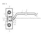
- FIG. 1 is a front cross-sectional view illustrating a water contaminant removing apparatus according to an embodiment of the present invention
- FIG. 2 is a left side elevation view of the water contaminant removing apparatus illustrated in FIG. 1 ;
- FIG. 3 is a partially enlarged perspective view illustrating the surroundings of an inlet of the water contaminant removing apparatus illustrated in FIG. 1 ;
- FIG. 4 is a view illustrating a configuration in which an extension pipe is added to the inlet of the intake pipe and a length adjustable pipe is disposed on the extension pipe.
- a water contaminant removing apparatus for removing water contaminants, such as oil, red algae, or green algae.
- the apparatus includes an intake pipe having an absorption cloth housing in which a scroll of absorption cloth is disposed to be movable along an upward-downward movement route.
- the scroll of absorption cloth moves through the fixing holes, and when no fixing holes are formed on the upward-downward movement route, the scroll of absorption cloth is able to be wound around a central axis of the absorption cloth housing.
- the absorption cloth housing is positioned in an upper and lower part of water or above or below a surface of water containing oil, red algae, or green algae. Water contaminants are taken in through the intake pipe from a second inlet.
- the water contaminant removing apparatus further includes an intake pump to which the intake pipe is connected.
- the intake pump takes in water such that the water contaminants taken in towards an outlet of the intake pipe;
- the water contaminant removing apparatus further includes the absorption cloth disposed adjacent to the second inlet of the intake pipe.
- the absorption cloth may be movably disposed in the second inlet to absorb the water contaminants.
- the pump may be configured such that the first inlet of the intake pipe is submerged in water and the second inlet of the intake pipe is disposed in front of the first inlet to surround the first inlet in a watertight manner, the diameter of the second inlet being greater than the diameter of the first inlet, and the second inlet extending from above to below the surface of water.
- a buoyancy unit may be disposed inside or outside of the intake pipe, the buoyancy unit allowing the second inlet to extend from above to below the surface of water and the first inlet to be submerged in water.
- the second inlet may have fixing holes in upper and lower portions thereof.
- the absorption cloth is movably fixed to the fixing holes such that the absorption cloth is not deflected in a transverse direction when water is introduced by the pump or the like.
- the water contaminant removing apparatus may further include a support film, such as a lattice-shaped support film, disposed in the inlet of the intake pipe.
- a support film such as a lattice-shaped support film
- the support film prevents the absorption cloth from being pushed backwards to prevent water from being taken in through the inlet.
- a first roller may be further provided above the intake pipe or in a portion of a body of a ship above the surface of water when the intake pipe is not provided, one edge of the absorption cloth being wound on an outer circumference of the first roller.
- a first motor may be connected to the first roller, the first motor having a handle, with which the first roller is manually rotated, a reduction gear, or a speed-reducing belt.
- An upper housing may be configured to surround the first roller on which the absorption cloth is wound.
- the upper housing has a first opening through which absorption cloth is movable downwards.
- the upper housing may fix the first motor.
- a second roller may be disposed below the intake pipe.
- the other edge of the absorption cloth is wound on an outer circumference of the second roller.
- a lower housing may be configured to surround the second roller on which the absorption cloth is wound.
- the lower housing has a second opening through which the absorption cloth is movable upwards.
- a first coupling member may be configured to couple the upper housing with the intake pipe.
- a second coupling member may be configured to couple the lower housing with the intake pipe.
- the upper housing and the lower housing are coupled using coupling members or are formed integrally to bring more portions of the absorption cloth into contact with the surface of water.
- the fixing holes may be formed in upper and lower portions of the second inlet on the upward-downward movement route such that the absorption cloth is movable.
- Water stoppers formed of an elastic material may be disposed in front of and behind the lower fixing hole of the second inlet to be attached in a compressive manner, thereby preventing water from entering or structures, such as a wall, are formed on edges of the lower fixing hole of the second inlet, thereby preventing water from entering, since, when water is introduced through the lower fixing hole in the intake pipe, an amount of force for taking in water through the second inlet in front of the intake pipe decreases, such that clean water is introduced through the lower fixing hole of the intake pipe.
- a length adjustable pipe is disposed on the second inlet or coupled using a coupling member to adjust a length of the intake pipe.
- a length-adjusting unit coupled to a side portion of the length adjustable pipe to adjust the length of the length adjustable pipe.
- the water contaminant removing apparatus as described above may be coupled with one selected from the group consisting of a ship, a submarine, a robot ship, a remote control (RC) ship, a robot submarine, and an RC submarine.
- an underwater camera disposed adjacent to an inlet of the length adjustable pipe that adjusts the length of the intake pipe.
- the water contaminant removing apparatus further includes a lighting unit disposed adjacent to the underwater camera to radiate light in a direction in which the underwater camera captures images.
- FIG. 1 is a front cross-sectional view illustrating a water contaminant removing apparatus according to the embodiment of the present invention.
- FIG. 2 is a left side elevation view of the water contaminant removing apparatus illustrated in FIG. 1 .
- FIG. 3 is a partially enlarged perspective view illustrating the surroundings of an inlet of the water contaminant removing apparatus illustrated in FIG. 1 .
- the water contaminant removing apparatus includes an intake pipe 1 , an intake pump 2 , and absorption cloth 3 .
- the intake pipe 1 has a first inlet 1 c submerged under the surface of water and a second inlet 1 a disposed in front of the first inlet 1 c of the pump.
- the diameter of the second inlet 1 a is greater than that of the first inlet 1 c such that the second inlet 1 a surrounds the first inlet 1 c in a watertight manner.
- the second inlet 1 a is disposed such that the second inlet 1 a extends from above to below the surface of water containing oil, red algae, or green algae. In the case of taking in water, the interior of the pipe is sufficiently filled with water.
- the intake pump 2 is connected to the intake pipe 1 .
- the intake pump 2 may be connected and coupled to a region of the body of the intake pipe 1 disposed above the surface of water.
- the intake pump 2 allows water contaminants to be taken through the inlet 1 a in the direction of an outlet 1 b of the intake pipe 1 .
- the absorption cloth 3 is disposed adjacent to the inlet 1 a of the intake pipe 1 to be movable with respect to the inlet 1 a in order to absorb water contaminants, such as oil, red algae, or green algae, introduced through the inlet 1 a.
- the intake pump 2 is driven to take in water containing water contaminants through the second inlet 1 a of the intake pipe 1 disposed on the surface of water.
- the absorption cloth 3 is periodically or continuously moved in the bottom-to-top direction, such that a clean portion of the absorption cloth 3 can be periodically or continuously arranged adjacent to the second inlet 1 a to remove water contaminants.
- the water contaminant removing apparatus can remove contaminants by periodically or continuously arranging a clean portion of the absorption cloth 3 adjacent to the first inlet 1 a without having an effect on the aquatic ecosystem, thereby removing water contaminants in a more efficient manner compared to the related-art method of manually removing water contaminants.
- the water contaminant removing apparatus further includes a first roller 4 , a first electric motor 5 , an upper housing 6 , a second roller 7 , and a lower housing 8 .
- the first roller 4 is disposed above the intake pipe 1 . In this case, one edge of the absorption cloth 3 is wound on the outer circumference of the first roller 4 .
- the first electric motor 5 is connected to the first roller 4 to rotate the first roller 4 .
- the upper housing 6 surrounds the first roller 4 on which the absorption cloth 3 is wound, has a first opening through which the absorption cloth 3 can move downwards, and surrounds the first electric motor 5 .
- the upper housing 6 defines a space in which the first electric motor 5 can be fixed, such that the first electric motor 5 and the first roller 4 can be fixed in a specific position.
- the upper housing 6 surrounds the contaminated absorption cloth 3 wound on the first roller 4 and the first electric motor 5 , thereby preventing debris of the absorption cloth 3 from being discharged externally or the electric motor from being short-circuited by water.
- the second roller 7 is disposed below the intake pipe 1 , and the other edge of the absorption cloth 3 is wound on the outer circumference of the second roller 7 .
- the lower housing 8 surrounds the second roller 7 on which the absorption cloth 3 is wound, and has a second opening through which the absorption cloth 3 can move upwards.
- the lower housing 8 has defined a space in which the second roller 7 can be rotatably fixed.
- fixing holes 3 a are formed in the upper and lower portions of the second inlet 1 a of the intake pipe 1 .
- the fixing holes 3 a serve to fix the absorption cloth 3 such that the absorption cloth 3 does not lean in the transverse direction when water is introduced using the pump or the like.
- Water stoppers formed of an elastic material are disposed in front of and behind the lower fixing hole of the second inlet 1 a and are attached in a compressive manner, thereby preventing water from entering.
- structures, such as a wall, are formed on the edges of the lower fixing hole of the second inlet 1 a , thereby preventing water from entering.
- the first roller 4 and the second roller 7 with the absorption cloth 3 wound thereon when the electric motor periodically or continuously rotates, the first roller 4 and the second roller 7 roll the absorption cloth 3 such that the absorption cloth 3 periodically or continuously moves in the second inlet 1 a .
- This causes the surfaces of clean portions of the absorption cloth 3 to absorb water contaminants, thereby improving absorption efficiency.
- the water contaminant removing apparatus may further include a first coupling member 9 and a second coupling member 10 .
- the first coupling member 9 is a coupling means, such as a fastening member or a weld, for coupling the upper housing 6 with the intake pipe 1 .
- the second coupling member 10 is a coupling means, such as a fastening member or a weld, for coupling the lower housing 8 with the intake pipe 1 .
- the first coupling member 9 and the second coupling member 10 couple the upper housing 6 and the lower housing 8 to the intake pipe 1 , such that the intake pipe 1 is formed integrally with the first roller 4 , upper housing 6 , the second roller 7 , the lower housing 8 , and the intake pump 2 . Accordingly, the water contaminant removing apparatus according to the embodiment of the present invention can be used while moving on the surface of water.
- the water contaminant removing apparatus is coupled to a water transport apparatus, such as a ship, a submarine, a robot ship, an RC ship, a robot submarine, and an RC submarine.
- a water transport apparatus such as a ship, a submarine, a robot ship, an RC ship, a robot submarine, and an RC submarine.
- the water contaminant removing apparatus may further include a lattice-shaped supporting film 13 .
- the lattice-shaped supporting film 13 is disposed on the inlet 1 a of the intake pipe 1 .
- the lattice-shaped supporting film 13 acts as a support film that supports the absorption cloth 3 to prevent the absorption cloth 3 from being deflected backwards in the intake pipe by the intake force of the pump.
- the water contaminant removing apparatus may further include a buoyancy unit 14 .
- the buoyancy unit 14 is a part, such as Styrofoam or air pockets, for generating buoyancy, and is coupled to the surrounding portion of the intake pipe 1 .
- the buoyancy unit 14 provides buoyancy allowing the intake pipe 1 to float on the surface of water, such that the water contaminant removing apparatus can move on the surface of water.
- the lower space of the inlet 1 a is disposed below the surface of water, and the upper space of the inlet 1 a is disposed above the surface of water, such that the intake pipe 1 is not completely submerged in water. This makes it possible to very easily remove water contaminants, such as oil, floating on the surface of water.
- the first inlet 1 c of the inner pipe disposed within the intake pipe 1 is submerged below the surface of water.
- the second inlet 1 a the diameter of which is greater than that of the first inlet 1 c , is disposed in front of the first inlet 1 c of the pump to surround the first inlet 1 c in a watertight manner.
- the second inlet 1 a is disposed to extend from above to below the surface of water, such that the intake pipe 1 is not completely submerged in water. This makes it possible to very easily remove water contaminants, such as oil, floating on the surface of water.
- FIG. 4 is a view illustrating a configuration in which an extension pipe 15 is added to the inlet 1 a of the intake pipe 1 and a length adjustable pipe 16 is disposed on the extension pipe 15 .
- the water contaminant removing apparatus may further include extension pipe 15 , the length adjustable pipe 16 , and a length-adjusting unit 17 .
- the extension pipe 15 is coupled with the inlet 1 a of the intake pipe 1 to communicate with the inlet 1 a of the intake pipe 1 .
- the length adjustable pipe 16 is implemented as a bellows or an elastic hose, the length of which is adjustable.
- the length adjustable pipe 16 is disposed on the inlet 1 a , or as illustrated in FIG. 4 , is disposed on the extension pipe 15 to communicate with the extension pipe 15 .
- the length-adjusting unit 17 is a transportable part, such as a hydraulic cylinder, coupled with the side portion of the length adjustable pipe 16 .
- a transportable part such as a hydraulic cylinder
- the axial end of a movable rod thereof is engaged with the length adjustable pipe 16
- the other axial end thereof is engaged with the intake pipe 1 or the extension pipe 15 .
- the length-adjusting unit 17 is driven in response to a signal input from an external source to adjust the length of the length adjustable pipe 16 .
- the length of the length adjustable pipe 16 is adjusted by the length-adjusting unit 17 , such that the water contaminant removing apparatus according to the present embodiment can selectively remove water contaminants in water.
- the water contaminant removing apparatus may further include an underwater camera 18 and a monitor 19 .
- the underwater camera 18 is disposed adjacent to the inlet 1 a.
- the monitor 19 works in concert with the underwater camera 18 to display images captured by the underwater camera 18 by receiving images therefrom.
- the underwater camera 18 and the monitor 19 notify an operator of underwater conditions, such that the operator can examine underwater contaminants on the monitor 19 and then selectively adjust the intake position of an intake port 16 a of the length adjustable pipe 16 using the length-adjusting unit 17 , thereby easily removing water contaminants.
- the water contaminant removing apparatus may further include a lighting unit 20 .
- the lighting unit 20 is disposed adjacent to the intake port of the length adjustable pipe 16 or the inlet 1 a of the intake pipe 1 in order to radiate light in the direction in which the underwater camera 18 captures images.
- the lighting unit 20 radiates light in the direction in which the underwater camera 18 captures images, such that the underwater camera 18 can easily capture images in dark underwater areas.
Applications Claiming Priority (17)
| Application Number | Priority Date | Filing Date | Title |
|---|---|---|---|
| KR10-2013-0125001 | 2013-10-20 | ||
| KR20130125001 | 2013-10-20 | ||
| KR10-2014-0003691 | 2014-01-13 | ||
| KR20140003691 | 2014-01-13 | ||
| KR1020140011879A KR20150091557A (ko) | 2014-02-02 | 2014-02-02 | 충격 진동 흡수 블록 |
| KR10-2014-0011879 | 2014-02-02 | ||
| KR10-2014-0013889 | 2014-02-06 | ||
| KR20140013889A KR20150046704A (ko) | 2013-10-20 | 2014-02-06 | 기름 유출, 적조, 녹조 제거 장치 |
| KR20140019296 | 2014-02-19 | ||
| KR10-2014-0019296 | 2014-02-19 | ||
| KR1020140089000A KR20150093567A (ko) | 2014-02-06 | 2014-07-15 | 수상오염물 제거장치 |
| KR10-2014-0089000 | 2014-07-15 | ||
| KR10-2014-0102743 | 2014-08-10 | ||
| KR20140102743A KR20150046719A (ko) | 2013-10-20 | 2014-08-10 | 수상오염물 제거장치 |
| KR10-2014-0138649 | 2014-10-14 | ||
| KR20140138649A KR20150046730A (ko) | 2013-10-20 | 2014-10-14 | 수상오염물 제거장치 |
| PCT/KR2014/009815 WO2015057029A1 (ko) | 2013-10-20 | 2014-10-19 | 수상오염물 제거장치 |
Publications (2)
| Publication Number | Publication Date |
|---|---|
| US20160265179A1 US20160265179A1 (en) | 2016-09-15 |
| US10240312B2 true US10240312B2 (en) | 2019-03-26 |
Family
ID=56050762
Family Applications (1)
| Application Number | Title | Priority Date | Filing Date |
|---|---|---|---|
| US15/030,603 Expired - Fee Related US10240312B2 (en) | 2013-10-20 | 2014-10-19 | Aquatic contaminator elimination device |
Country Status (4)
| Country | Link |
|---|---|
| US (1) | US10240312B2 (zh) |
| EP (1) | EP3059348A4 (zh) |
| JP (1) | JP2017505863A (zh) |
| CN (1) | CN105637148A (zh) |
Families Citing this family (10)
| Publication number | Priority date | Publication date | Assignee | Title |
|---|---|---|---|---|
| CN107130574B (zh) * | 2017-05-30 | 2019-04-16 | 中煤(北京)环保工程有限公司 | 一种环境水处理浒苔自动回收防护网绳 |
| CN107323625A (zh) * | 2017-08-17 | 2017-11-07 | 岑全振 | 一种改善海底环境用除草设备 |
| CN108343040A (zh) * | 2018-03-07 | 2018-07-31 | 广州尚儒自控系统工程有限公司 | 一种改进型的系统生态功能区恢复装置 |
| CN109078888B (zh) * | 2018-09-13 | 2023-08-18 | 黄河机械有限责任公司 | 渠道边坡除藻设备 |
| CN109673252B (zh) * | 2018-12-25 | 2021-11-23 | 交通运输部天津水运工程科学研究所 | 基于大数据分析监测的浒苔自动打捞脱水系统及监控方法 |
| CN111533299B (zh) * | 2020-05-22 | 2022-05-13 | 贵州巨美环境科技有限公司 | 一种工业污水处理用具有分离结构的过滤机构 |
| CN111926785A (zh) * | 2020-07-31 | 2020-11-13 | 于守美 | 一种浮油收集装置 |
| CN112811512B (zh) * | 2021-01-07 | 2022-08-09 | 穆江山 | 一种交通服务区污水处理装置 |
| CN114973771B (zh) * | 2022-04-15 | 2024-02-09 | 重庆交通大学 | 一种桥梁主动防船撞方法 |
| CN116062104B (zh) * | 2023-03-06 | 2023-06-02 | 四川省生态环境科学研究院 | 饮用水源污染物打捞装置 |
Citations (11)
| Publication number | Priority date | Publication date | Assignee | Title |
|---|---|---|---|---|
| US3643804A (en) * | 1970-09-24 | 1972-02-22 | Dallas E Sharpton | Waste oil recovery unit |
| US3763049A (en) * | 1971-07-16 | 1973-10-02 | A Gerber | Process for the continuous recovery of materials from sea water |
| US4145290A (en) * | 1977-07-28 | 1979-03-20 | Nagy Charles E | Skimmer for oil spills |
| KR940004152B1 (ko) | 1985-10-28 | 1994-05-13 | 아메리칸 텔리폰 앤드 텔레그라프 캄파니 | 모듀울 어댑터 및 그의 제조방법 |
| US5532679A (en) * | 1993-08-05 | 1996-07-02 | Baxter, Jr.; John F. | Oil spill detection system |
| KR0132082Y1 (ko) | 1996-04-06 | 1999-03-30 | 이도형 | 해양오염 방지용 오일 방재선 |
| KR20000066838A (ko) | 1999-04-21 | 2000-11-15 | 김복중 | 기름 수거 선박 |
| US20050035070A1 (en) * | 2001-10-04 | 2005-02-17 | Richard Egli | Device and method for the removal of oil or floating materials from a water surface |
| KR100851669B1 (ko) | 2008-02-28 | 2008-08-18 | 김주회 | 유출유 확산방지 및 회수장치 |
| KR200452158Y1 (ko) | 2008-04-18 | 2011-02-10 | 조병호 | 해상 오염 크리닝 장치 |
| KR101221579B1 (ko) | 2012-10-12 | 2013-01-14 | 김규홍 | 선박에 구비된 녹조 및 적조 제거장치 |
Family Cites Families (7)
| Publication number | Priority date | Publication date | Assignee | Title |
|---|---|---|---|---|
| JPS5326451B2 (zh) * | 1972-04-26 | 1978-08-02 | ||
| JPS51143955A (en) * | 1975-06-05 | 1976-12-10 | Shin Meiwa Ind Co Ltd | Device for purifying sea surface |
| US4165282A (en) * | 1976-02-26 | 1979-08-21 | Bennett Pollution Controls Ltd. | Oil recovery method and apparatus |
| JP3910696B2 (ja) * | 1997-09-17 | 2007-04-25 | 日▲吉▼海運株式会社 | 油回収装置、および油回収船 |
| JP4263032B2 (ja) * | 2003-06-26 | 2009-05-13 | 国土交通省四国地方整備局長 | 真空吸引油回収システム |
| CN2887956Y (zh) * | 2005-12-22 | 2007-04-11 | 上海交通大学 | 海上大面积浮油收集与处理装置 |
| CN103254873B (zh) * | 2013-06-04 | 2015-11-25 | 南京工业大学 | 一种连续的可升降式履带快速吸油材料水面吸油装置 |
-
2014
- 2014-10-19 CN CN201480057594.8A patent/CN105637148A/zh active Pending
- 2014-10-19 EP EP14853483.7A patent/EP3059348A4/en not_active Withdrawn
- 2014-10-19 JP JP2016525053A patent/JP2017505863A/ja active Pending
- 2014-10-19 US US15/030,603 patent/US10240312B2/en not_active Expired - Fee Related
Patent Citations (11)
| Publication number | Priority date | Publication date | Assignee | Title |
|---|---|---|---|---|
| US3643804A (en) * | 1970-09-24 | 1972-02-22 | Dallas E Sharpton | Waste oil recovery unit |
| US3763049A (en) * | 1971-07-16 | 1973-10-02 | A Gerber | Process for the continuous recovery of materials from sea water |
| US4145290A (en) * | 1977-07-28 | 1979-03-20 | Nagy Charles E | Skimmer for oil spills |
| KR940004152B1 (ko) | 1985-10-28 | 1994-05-13 | 아메리칸 텔리폰 앤드 텔레그라프 캄파니 | 모듀울 어댑터 및 그의 제조방법 |
| US5532679A (en) * | 1993-08-05 | 1996-07-02 | Baxter, Jr.; John F. | Oil spill detection system |
| KR0132082Y1 (ko) | 1996-04-06 | 1999-03-30 | 이도형 | 해양오염 방지용 오일 방재선 |
| KR20000066838A (ko) | 1999-04-21 | 2000-11-15 | 김복중 | 기름 수거 선박 |
| US20050035070A1 (en) * | 2001-10-04 | 2005-02-17 | Richard Egli | Device and method for the removal of oil or floating materials from a water surface |
| KR100851669B1 (ko) | 2008-02-28 | 2008-08-18 | 김주회 | 유출유 확산방지 및 회수장치 |
| KR200452158Y1 (ko) | 2008-04-18 | 2011-02-10 | 조병호 | 해상 오염 크리닝 장치 |
| KR101221579B1 (ko) | 2012-10-12 | 2013-01-14 | 김규홍 | 선박에 구비된 녹조 및 적조 제거장치 |
Non-Patent Citations (1)
| Title |
|---|
| International Search Report for PCT/KR2014/009815 dated Feb. 16, 2015 from Korean Intellectual Property Office. |
Also Published As
| Publication number | Publication date |
|---|---|
| EP3059348A1 (en) | 2016-08-24 |
| CN105637148A (zh) | 2016-06-01 |
| EP3059348A4 (en) | 2017-07-05 |
| JP2017505863A (ja) | 2017-02-23 |
| US20160265179A1 (en) | 2016-09-15 |
Similar Documents
| Publication | Publication Date | Title |
|---|---|---|
| US10240312B2 (en) | Aquatic contaminator elimination device | |
| Dhaka et al. | A review on physical remediation techniques for treatment of marine oil spills | |
| KR101709143B1 (ko) | 수중 오염원의 제거장치 및 제거방법 | |
| JP2017516935A (ja) | 水底上に沈積した可塑性の泥状物質の収集および除去用装置 | |
| Mrowiec | Plastic pollutants in water environment | |
| KR100851669B1 (ko) | 유출유 확산방지 및 회수장치 | |
| Ahmed et al. | Microplastics in aquatic environments: A comprehensive review of toxicity, removal, and remediation strategies | |
| Sharma et al. | Understanding microplastic pollution of marine ecosystem: a review | |
| KR101644866B1 (ko) | 스크래퍼 타입의 피처리수 여과장치 | |
| KR101412598B1 (ko) | 선박평형수 처리장치 | |
| CN114212949A (zh) | 一种用于畜牧业的海藻爆发海域用海水净化装置 | |
| EP3652059B1 (en) | Method and system for treatment of an underwater surface and material removed from it | |
| KR101832271B1 (ko) | 다목적 해양 오염 방제선박 | |
| KR101552121B1 (ko) | 선저의 부착물 회수장치 | |
| CN106587454A (zh) | 一种车载式突发水污染事故应急净化系统 | |
| KR101627716B1 (ko) | 스크류 타입의 피처리수 여과장치 | |
| RU2505489C1 (ru) | Способ биологической очистки литоральной зоны морей от нефтепродуктов | |
| CN101973369A (zh) | 多功能水环境灾害应急处理船及使用该装置的水污染处理方法 | |
| HUT70676A (en) | Purification of water contaminated with kerosene, oil, petrol and ther organic materials by means of and adsorptional process, adsorptional modules, method and apparatus for purifying such water | |
| KR20180003488U (ko) | 수상오염물 제거장치 | |
| KR20060128458A (ko) | 산업 시설 배출수 처리 시스템 및 그 방법 | |
| CN219930914U (zh) | 一种水藻打捞装置 | |
| KR200237418Y1 (ko) | 수중 슬러지 흡입기의 보조이동장치 | |
| KR20180001109A (ko) | 수상오염물 제거장치 | |
| US20220290393A1 (en) | Devices, systems, and methods for removing waste from bodies of water |
Legal Events
| Date | Code | Title | Description |
|---|---|---|---|
| FEPP | Fee payment procedure |
Free format text: ENTITY STATUS SET TO MICRO (ORIGINAL EVENT CODE: MICR); ENTITY STATUS OF PATENT OWNER: SMALL ENTITY |
|
| STCF | Information on status: patent grant |
Free format text: PATENTED CASE |
|
| FEPP | Fee payment procedure |
Free format text: MAINTENANCE FEE REMINDER MAILED (ORIGINAL EVENT CODE: REM.); ENTITY STATUS OF PATENT OWNER: SMALL ENTITY |
|
| LAPS | Lapse for failure to pay maintenance fees |
Free format text: PATENT EXPIRED FOR FAILURE TO PAY MAINTENANCE FEES (ORIGINAL EVENT CODE: EXP.); ENTITY STATUS OF PATENT OWNER: SMALL ENTITY |
|
| STCH | Information on status: patent discontinuation |
Free format text: PATENT EXPIRED DUE TO NONPAYMENT OF MAINTENANCE FEES UNDER 37 CFR 1.362 |
|
| FP | Lapsed due to failure to pay maintenance fee |
Effective date: 20230326 |