US10202086B2 - Tailgate - Google Patents
Tailgate Download PDFInfo
- Publication number
- US10202086B2 US10202086B2 US15/276,298 US201615276298A US10202086B2 US 10202086 B2 US10202086 B2 US 10202086B2 US 201615276298 A US201615276298 A US 201615276298A US 10202086 B2 US10202086 B2 US 10202086B2
- Authority
- US
- United States
- Prior art keywords
- garnish
- outer panel
- switch unit
- tailgate
- mounting
- Prior art date
- Legal status (The legal status is an assumption and is not a legal conclusion. Google has not performed a legal analysis and makes no representation as to the accuracy of the status listed.)
- Active, expires
Links
Images


Classifications
-
- B—PERFORMING OPERATIONS; TRANSPORTING
- B60—VEHICLES IN GENERAL
- B60J—WINDOWS, WINDSCREENS, NON-FIXED ROOFS, DOORS, OR SIMILAR DEVICES FOR VEHICLES; REMOVABLE EXTERNAL PROTECTIVE COVERINGS SPECIALLY ADAPTED FOR VEHICLES
- B60J5/00—Doors
- B60J5/10—Doors arranged at the vehicle rear
- B60J5/101—Doors arranged at the vehicle rear for non-load transporting vehicles, i.e. family cars including vans
- B60J5/107—Doors arranged at the vehicle rear for non-load transporting vehicles, i.e. family cars including vans constructional details, e.g. about door frame, panels, materials used, reinforcements
-
- B—PERFORMING OPERATIONS; TRANSPORTING
- B60—VEHICLES IN GENERAL
- B60R—VEHICLES, VEHICLE FITTINGS, OR VEHICLE PARTS, NOT OTHERWISE PROVIDED FOR
- B60R13/00—Elements for body-finishing, identifying, or decorating; Arrangements or adaptations for advertising purposes
- B60R13/04—External Ornamental or guard strips; Ornamental inscriptive devices thereon
-
- B—PERFORMING OPERATIONS; TRANSPORTING
- B60—VEHICLES IN GENERAL
- B60J—WINDOWS, WINDSCREENS, NON-FIXED ROOFS, DOORS, OR SIMILAR DEVICES FOR VEHICLES; REMOVABLE EXTERNAL PROTECTIVE COVERINGS SPECIALLY ADAPTED FOR VEHICLES
- B60J5/00—Doors
- B60J5/10—Doors arranged at the vehicle rear
- B60J5/101—Doors arranged at the vehicle rear for non-load transporting vehicles, i.e. family cars including vans
-
- E—FIXED CONSTRUCTIONS
- E05—LOCKS; KEYS; WINDOW OR DOOR FITTINGS; SAFES
- E05F—DEVICES FOR MOVING WINGS INTO OPEN OR CLOSED POSITION; CHECKS FOR WINGS; WING FITTINGS NOT OTHERWISE PROVIDED FOR, CONCERNED WITH THE FUNCTIONING OF THE WING
- E05F15/00—Power-operated mechanisms for wings
- E05F15/70—Power-operated mechanisms for wings with automatic actuation
- E05F15/73—Power-operated mechanisms for wings with automatic actuation responsive to movement or presence of persons or objects
-
- E—FIXED CONSTRUCTIONS
- E05—LOCKS; KEYS; WINDOW OR DOOR FITTINGS; SAFES
- E05Y—INDEXING SCHEME RELATING TO HINGES OR OTHER SUSPENSION DEVICES FOR DOORS, WINDOWS OR WINGS AND DEVICES FOR MOVING WINGS INTO OPEN OR CLOSED POSITION, CHECKS FOR WINGS AND WING FITTINGS NOT OTHERWISE PROVIDED FOR, CONCERNED WITH THE FUNCTIONING OF THE WING
- E05Y2900/00—Application of doors, windows, wings or fittings thereof
- E05Y2900/50—Application of doors, windows, wings or fittings thereof for vehicles
- E05Y2900/53—Application of doors, windows, wings or fittings thereof for vehicles characterised by the type of wing
- E05Y2900/531—Doors
- E05Y2900/532—Back doors or end doors
Definitions
- the present invention relates to the tailgate of a vehicle.
- a tailgate including a switch with which a passenger instructs the opening operation of the tailgate is known as a tailgate for opening/closing an opening on the rear part of a vehicle.
- Japanese Patent No. 5310435 discloses a structure in which such switch is mounted on the outer panel of a tailgate, and covered with a garnish.
- the switch of the tailgate Since the switch of the tailgate is to be operated by a passenger, an operation load may be applied by the passenger to the switch and the garnish around it, and some passengers may apply an operation load more than necessary. A portion of the tailgate around the switch is externally exposed, and may be applied with some external force. Therefore, the switch and the portion around it are desirably, sufficiently resistant to an operation load or external force, and the conventional structure has room for improvement in this point.
- the present invention enables improvement of the rigidity of a tailgate around a switch.
- a tailgate for opening/closing an opening of a vehicle, comprising: an outer panel configured to form an outer surface of the tailgate; a garnish mounted on the outer panel and configured to form the outer surface of the tailgate; and a switch unit including at least a switch configured to instruct an opening operation of the tailgate, wherein the switch unit is arranged in a space between the outer panel and the garnish, and mounted on the outer panel and the garnish.
- FIG. 1A is a front view showing a tailgate according to an embodiment
- FIG. 1B is a bottom view showing the tailgate
- FIG. 1C is a partially enlarged view showing the tailgate
- FIGS. 2A and 2B are views each showing the outer appearance of a switch unit
- FIGS. 3A and 3B are views each showing the outer appearance of the switch unit
- FIGS. 4A and 4B are views each showing the outer appearance of the switch unit
- FIGS. 5A and 5B are views each showing the outer appearance of a bracket
- FIG. 6 is a view showing a state in which the switch unit is mounted on a garnish
- FIG. 7 is a sectional view taken along a line I-I in FIG. 1A and showing a portion around the garnish;
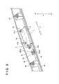
- FIG. 8 is a sectional view taken along a line II-II in FIG. 1A and showing the portion around the garnish;
- FIG. 9 is a sectional view taken along a line III-III in FIG. 1A and showing the portion around the garnish.
- an arrow FR indicates the front-and-rear direction of a vehicle and FT and RR respectively indicate front and rear sides.
- An arrow W indicates a vehicle width direction and LT and RT respectively indicate left and right sides when viewed from the advancing direction of the vehicle.
- An arrow H indicates a vertical direction and UR and LR respectively indicate upper and lower sides.
- FIG. 1A is a front view showing a tailgate 1 (semi-assembled state) according to an embodiment of the present invention, and corresponds to a rear view of a vehicle when the tailgate is assembled in the vehicle.
- FIG. 1B is a bottom view showing the tailgate 1
- FIG. 1C is a partially enlarged view of FIG. 1B .
- the tailgate 1 is a door for opening/closing an opening on the rear part of the vehicle.
- the tailgate 1 is assembled in the vehicle to pivot about a line L in FIG. 1A in the vertical direction.
- the tailgate 1 is applicable to various automobiles, for example, a minivan, SUV, and station wagon.
- the tailgate 1 includes an outer panel 2 and a garnish 3 .
- the outer panel 2 is a member forming most of the outer surface of the tailgate 1 .
- the outer panel 2 includes an opening 21 to which a rear windshield is attached, and a concave portion 23 forming a mounting portion for a license plate.
- the garnish 3 is a decoration body which extends in the vehicle width direction along the upper edge of the concave portion 23 .
- the garnish 3 is mounted on the outer panel 2 , and forms part of the outer surface of the tailgate 1 .
- a switch unit 4 is disposed in the garnish 3 .
- the switch unit 4 is a unit which includes an operation portion 54 facing downward, and includes, in the operation portion 54 , an open switch 54 a for instructing the open operation of the tailgate 1 .
- an open switch 54 a for instructing the open operation of the tailgate 1 .
- the tailgate 1 automatically pivots to open the opening on the rear part of the vehicle.
- a switch for example, a smart switch
- a light emitting device for example, an LED
- FIGS. 2A to 4B are views each showing the outer appearance of the switch unit 4 .
- FIGS. 5A and 5B are views each showing the outer appearance of a bracket 6 included in the switch unit 4 when a main body portion 5 is detached from the switch unit 4 .
- the arrows FR, W, and H in FIGS. 2A to 5B are based on a case in which the switch unit 4 is mounted on the vehicle and the tailgate 1 is in a closed state.
- the switch unit 4 includes the main body portion 5 and the bracket 6 .
- the main body portion 5 is a portion including an electric circuit with the open switch 54 a .
- the bracket 6 is a portion mounted on the outer panel 2 and the garnish 3 .
- the main body portion 5 includes a case 51 which accommodates the electric circuit with the open switch 54 a .
- the case 51 is a hollow body including a concave portion 51 b open to the lower side, and the operation portion 54 is located on the far side of the concave portion 51 b .
- a flange portion 51 a projecting outward is formed at the lower end of the concave portion 51 b to rim the opening of the concave portion 51 b.
- An engaging piece 52 is formed in a portion on one side of the case 51 in the vehicle width direction.
- the engaging piece 52 has an upper end integrally connected to the side wall of the case 51 , and a pawl portion at a lower end, and is elastically deformable in the vehicle width direction around the upper end.
- an engaging pawl 53 is integrally formed in a lower portion on the other side of the case 51 in the vehicle width direction.
- the main body portion 5 is mounted on the bracket 6 by sandwiching a frame portion 621 of the bracket 6 between the pawl portion of the engaging piece 52 and the flange portion 51 a while sandwiching the frame portion 621 of the bracket 6 between the engaging pawl 53 and the flange portion 51 a .
- the main body portion 5 is detachably attached to the bracket 6 by elastic deformation of the engaging piece 52 .
- a coupler 55 is provided in the portion on the other side of the case 51 in the vehicle width direction.
- An electric wire (harness) for electrically connecting the control unit of the vehicle and the electric circuit of the main body portion 5 is connected to the coupler 55 . Connection of the electric wire allows power supply of the electric circuit including the open switch 54 a and transmission of a signal to the control unit.
- the insertion/extraction direction of the electric wire for the coupler 55 is the vehicle width direction.
- the bracket 6 is formed to surround the main body portion 5 . This can protect the main body portion 5 from an external force with the bracket 6 .
- the bracket 6 is constituted by two members, and includes an upper frame body 61 and a lower frame body 62 .
- the bracket 6 can be constituted by one member, it is possible to relatively easily create an arrangement to surround the main body portion 5 by constituting the bracket 6 by two members.
- the upper frame body 61 is a frame body constituting the upper side of the bracket 6 , which extends in the vehicle width direction and has a shape in which the two ends in the vehicle width direction are bent downward. Portions 613 and 614 bent downward are fixed to the lower frame body 62 by welding or the like. A central portion 615 is also fixed to the lower frame body 62 by welding or the like.
- a mounting member 611 and a positioning member 612 are provided in the upper frame body 61 to project upward.
- the mounting member 611 is a member for mounting the garnish 3 and the switch unit 4 on the outer panel 2 at one position.
- the upper portion of the mounting member 611 is engaged with the outer panel 2 and an engaging portion 611 a of the lower portion of the mounting member 611 is engaged with the garnish 3 .
- the positioning member 612 is a positioning pin inserted into a positioning hole formed in the outer panel 2 .
- the lower frame body 62 is a frame body constituting the lower side of the bracket 6 , and includes the frame portion 621 forming an opening 621 a to expose the operation portion 54 of the main body portion 5 .
- the frame portion 621 is formed to overlap the flange portion 51 a , and can protect a portion around the operation portion 54 by the frame portion 621 .
- Portions 623 and 624 bent upward are formed at the two ends of the frame portion 621 in the vehicle width direction. These portions 623 and 624 are respectively fixed to the portions 613 and 614 of the upper frame body 61 by welding or the like.
- a portion 625 bent upward is formed in the central portion of the frame portion 621 in the vehicle width direction on the rear part in the vehicle width direction. The portion 625 is fixed to the portion 615 of the upper frame body 61 by welding or the like.
- the lower frame body 62 includes an extension portion 622 extending from the frame portion 621 in the vehicle width direction.
- a mounting portion 622 a is formed at the end of the extension portion 622 , and mounted on the garnish 3 by a mounting member 622 b .
- FIG. 6 is a view showing a state in which the switch unit 4 is mounted on the garnish 3 , and shows the interior of the garnish 3 .
- FIG. 7 is a sectional view taken along a line I-I in FIG. 1A and showing a portion around the garnish 3 .
- FIG. 8 is a sectional view taken along a line II-II in FIG. 1A and showing the portion around the garnish 3 .
- FIG. 9 is a sectional view taken along a line III-III in FIG. 1A and showing the portion around the garnish 3 .
- the garnish 3 includes a wall portion 31 and a wall portion 32 continuing from the wall portion 31 through a corner 33 , and has an L-shaped vertical sectional shape.
- the wall portion 31 is formed along the surface of the outer panel 2 , and the surface of the wall portion 31 almost continues from the surface of the outer panel 2 .
- the wall portion 32 continues from the wall portion 31 to have an angle (about 90° in this example) with respect to the wall portion 31 , and extends almost in the horizontal direction in this embodiment. Seal members 39 extend at the edges of the wall portions 31 and 32 .
- Mounting members 37 and 38 are spaced apart from each other in the vehicle width direction, and fixed inside the garnish 3 .
- the mounting members 37 and 38 are members used to fix the garnish 3 and outer panel 2 , and are respectively mounted on mounting portions 24 and 25 provided in the outer panel 2 .
- the mounting portions 24 and 25 respectively have holes into which the mounting members 37 and 38 are inserted.
- the switch unit 4 is arranged in a space S between the outer panel 2 and the garnish 3 (a space surrounded by the outer panel 2 and the garnish 3 ).
- a mounting portion 34 is provided inside the corner portion 33 of the garnish 3 .
- the mounting portion 34 has a hole into which the mounting member 622 b is inserted. When the mounting member 622 b is inserted into the hole, the mounting portion 34 and the mounting member 622 b are engaged, and thus the mounting portion 622 a of the extension portion 622 is fixed to the mounting portion 34 .
- the mounting portion 34 is formed in the corner portion 33 to bridge the wall portions 31 and 32 . Since the mounting portion 34 is provided in the corner portion 33 where the rigidity is increased, the mounting rigidity of the switch unit 4 can be improved.
- a rib 35 is integrally formed in the garnish 3 .
- the mounting portion 36 engaged with the engaging portion 611 a of the mounting member 611 is provided in the rib 35 .
- a mounting portion 36 is a groove open to the right side in the vehicle width direction (see FIG. 9 ), and is configured so that the engaging portion 611 a and the mounting portion 36 are engaged with each other by moving the engaging portion 611 a from the right side to the left side in the vehicle width direction to fit in the mounting portion 36 .
- the mounting member 611 is mounted on a mounting portion 26 provided in the outer panel 2 .
- the mounting portion 26 has a hole into which the upper portion of the mounting member 611 is inserted. When the upper portion of the mounting member 611 is inserted into the hole, the mounting portion 26 and the mounting member 611 are engaged.
- the mounting member 611 fixes the outer panel 2 , the garnish 3 , and the switch unit 4 at one position.
- the switch unit 4 is assembled in the garnish 3 first, as shown in FIG. 6 .
- the engaging portion 611 a is engaged with the mounting portion 36 , and then the mounting portion 622 a is mounted on the mounting portion 34 by the mounting member 622 b.
- the switch unit 4 has two mounting portions (the engaging portion 611 a of the mounting member 611 and the mounting portion 622 a ) for the garnish 3 .
- the two mounting portions can be spaced apart from each other by providing the mounting portion 622 a at the end of the extension portion 622 . This stabilizes fixing of the switch unit 4 to the garnish 3 .
- the main body portion 5 and the mounting portion 622 a are arranged in the vehicle width direction, it is possible to ensure a wider space in the front-and-rear direction of the vehicle or the vertical direction as the arrangement space of the main body portion 5 . Therefore, with respect to the shape of the main body portion 5 , the degree of freedom in the front-and-rear direction of the vehicle or the vertical direction can be improved. Alternatively, it is also possible to ensure, for the main body portion 5 , a wider gap i the front-and-rear direction of the vehicle or the vertical direction, and to delay the interference of the main body portion 5 with its surrounding portion at the time of input of an external force, thereby facilitating prevention of damage.
- the coupler 55 is located on the side of the extension portion 622 in the vehicle width direction with respect to a central portion C ( FIG. 6 ) of the main body portion 5 in the vehicle width direction. Since the coupler 55 is located adjacent to the extension portion 622 whose rigidity becomes relatively high by mounting on the mounting portion 622 a , it is possible to reduce the possibility that the coupler 55 is damaged upon input of an external force. Note that the arrangement space of the connector of the electric wire connected to the coupler 55 is ensured by providing the mounting portion 622 a at the end of the extension portion 622 .
- the garnish 3 in which the switch unit 4 has been assembled is pressed into the outer panel 2 , and is thus fixed to the outer panel 2 .
- the positioning member 612 of the switch unit 4 is inserted into a positioning hole 27 of the outer panel 2 , which is used as a guide to press the garnish 3 into the outer panel 2 , thereby facilitating alignment between the respective portions.
- the switch unit 4 is mounted on both the outer panel 2 and the garnish 3 .
- the switch unit 4 (especially, the bracket 6 ) functions as a reinforcing member for connecting the outer panel 2 and the garnish 3 in the space S between them. Therefore, the mounting rigidity of the switch unit 4 is improved, and the support rigidity of the garnish 3 is improved by supporting the garnish 3 by the switch unit 4 . Consequently, it is possible to improve the rigidity of the tailgate 1 around the open switch 54 a.
- the number of mounting portions can be decreased to reduce the number of parts and the number of processes, as compared with an arrangement in which a plurality of mounting portions each for fixing two of the three members are provided. Since the mounting member 611 co-fastens the plurality of members, the rigidity of the mounting portion can be improved.
- a plurality of portions for fixing three members like the mounting portion 26 can be provided, only one such portion is provided in this embodiment.
- the outer panel 2 , the garnish 3 , and the switch unit 4 may have different properties such as heat deformation amounts. If a plurality of portions for fixing three members are provided, it is necessary to perform design in consideration of the distortion amount of each member and the like. By providing only one such portion as in this embodiment, such consideration becomes unnecessary and a relatively simple structure can be obtained.
- a tailgate for example, 1 for opening/closing an opening of a vehicle, comprising:
- an outer panel (for example, 2 ) configured to form an outer surface of the tailgate
- a garnish (for example, 3 ) mounted on the outer panel and configured to form the outer surface of the tailgate;
- a switch unit for example, 4 including at least a switch (for example, 54 a ) configured to instruct an opening operation of the tailgate,
- switch unit is arranged in a space (for example, S) between the outer panel and the garnish, and mounted on the outer panel and the garnish (for example, 26 , 34 ).
- the switch unit since the switch unit is mounted on both the outer panel and the garnish, the mounting rigidity of the switch unit is improved, and the support rigidity of the garnish is improved by supporting the garnish by the switch unit. Consequently, it is possible to improve the rigidity of the tailgate around the switch.
- the tailgate (for example, 1 ), wherein
- the garnish includes a first wall portion (for example, 31 ) along a surface of the outer panel, and a second wall portion (for example, 32 ) continuing from the first wall portion through a corner portion (for example, 33 ), and
- the switch unit is mounted on the garnish in a mounting portion (for example, 34 ) provided in the corner portion.
- the rigidity of the garnish can be improved by the shape.
- the mounting portion of the switch unit is provided in the corner portion, the mounting rigidity of the switch unit is also improved.
- the tailgate (for example, 1 ), wherein
- the switch unit includes a main body portion (for example, 5 ) in which the switch is provided, and an extension portion (for example, 622 ) extending from the main body portion in a vehicle width direction, and
- the extension portion is mounted on the mounting portion.
- the main body portion and the mounting portion are arranged in the vehicle width direction, it is possible to ensure a wider space in the front-and-rear direction of the vehicle or the vertical direction as the arrangement space of the main body portion. Therefore, with respect to the shape of the main body portion, the degree of freedom in the front-and-rear direction of the vehicle or the vertical direction can be improved. Alternatively, it is possible to ensure, for the main body portion, a wider gap in the front-and-rear direction of the vehicle or the vertical direction, and to delay the interference of the main body portion with its surrounding portion at the time of input of an external force, thereby facilitating prevention of damage.
- the tailgate (for example, 1 ), wherein
- the main body portion includes a coupler (for example, 55 ) to which an electric wire is connected, and
- the coupler is located on a side of the extension portion in the vehicle width direction with respect to a central portion (for example, C) of the main body portion in the vehicle width direction.
- the tailgate (for example, 1 ), further comprising:
- a mounting member (for example, 612 ) configured to mount the garnish and the switch unit on the outer panel at one position.
- the number of mounting portions can be decreased to reduce the number of parts and the number of processes. Furthermore, since the mounting member fixes the plurality of members, the rigidity of the mounting portion can be improved.
- the tailgate (for example, 1 ), wherein
- the tailgate (for example, 1 ), wherein
- the switch unit includes a main body portion (for example, 5 ) in which the switch is provided, and a bracket (for example, 6 ) configured to support the main body portion to surround the main body portion, and
- the bracket is mounted on the outer panel and the garnish.
- the main body portion can be protected by the bracket.
- the tailgate (for example, 1 ), wherein
- the bracket includes a first member (for example, 61 ) including a first mounting portion (for example, 611 ) mounted on the outer panel, and a second member (for example, 62 ) including a second mounting portion (for example, 622 a , 622 b ) mounted on the garnish, and
- the first member and the second member are fixed.
- the tailgate (for example, 1 ), wherein
- the second member includes a frame portion (for example, 621 ) configured to form an opening (for example, 621 a ) to expose an operation portion of the main body portion, and an extension portion (for example, 622 ) extending from the frame portion in the vehicle width direction and including the second mounting portion.
- a frame portion for example, 621
- an opening for example, 621 a
- an extension portion for example, 622
Applications Claiming Priority (2)
| Application Number | Priority Date | Filing Date | Title |
|---|---|---|---|
| JP2015190300A JP6342867B2 (ja) | 2015-09-28 | 2015-09-28 | テールゲート |
| JP2015-190300 | 2015-09-28 |
Publications (2)
| Publication Number | Publication Date |
|---|---|
| US20170089125A1 US20170089125A1 (en) | 2017-03-30 |
| US10202086B2 true US10202086B2 (en) | 2019-02-12 |
Family
ID=58406821
Family Applications (1)
| Application Number | Title | Priority Date | Filing Date |
|---|---|---|---|
| US15/276,298 Active 2037-03-01 US10202086B2 (en) | 2015-09-28 | 2016-09-26 | Tailgate |
Country Status (3)
| Country | Link |
|---|---|
| US (1) | US10202086B2 (ja) |
| JP (1) | JP6342867B2 (ja) |
| CN (1) | CN107009857B (ja) |
Families Citing this family (3)
| Publication number | Priority date | Publication date | Assignee | Title |
|---|---|---|---|---|
| JP6727258B2 (ja) * | 2018-07-20 | 2020-07-22 | 本田技研工業株式会社 | 自動車のバックドア構造 |
| CN110284782A (zh) * | 2019-07-08 | 2019-09-27 | 烟台三环锁业集团股份有限公司 | 一种空间传动吸合机构 |
| CN115071838B (zh) * | 2022-08-03 | 2023-11-28 | 浙江吉利控股集团有限公司 | 一种汽车尾门及汽车 |
Citations (10)
| Publication number | Priority date | Publication date | Assignee | Title |
|---|---|---|---|---|
| US6123384A (en) * | 1997-06-02 | 2000-09-26 | Valeo Systemes D'essuyage | Motor vehicle tailgate comprising an accessory mounting plate |
| US6834906B2 (en) * | 2002-12-30 | 2004-12-28 | Valeo Electrical Systems, Inc. | Vehicle liftgate with component module applique |
| JP2006282035A (ja) | 2005-04-01 | 2006-10-19 | Toyota Auto Body Co Ltd | 車両の電装部品付き外板装飾部材及びその取り付け構造 |
| JP2010105425A (ja) | 2008-10-28 | 2010-05-13 | Nissan Motor Co Ltd | スイッチを有する外装部品の組付方法及び組付構造 |
| US8132847B2 (en) * | 2006-09-27 | 2012-03-13 | Honda Motor Co., Ltd. | Garnish for vehicle, having U-shaped recessed portion, which is integrally formed along edge in longitudinal direction |
| US8333495B2 (en) * | 2007-11-13 | 2012-12-18 | Stoneridge Control Devices, Inc. | Device for illuminating target surface including an integrated switch |
| JP5310435B2 (ja) | 2009-09-18 | 2013-10-09 | 三菱自動車工業株式会社 | テールゲート用オープンスイッチ誤操作防止構造 |
| US8646831B2 (en) * | 2010-04-26 | 2014-02-11 | Honda Motor Co., Ltd. | Mounting structure for an automotive exterior member |
| JP2014172572A (ja) | 2013-03-12 | 2014-09-22 | Mitsubishi Automob Eng Co Ltd | 車両用ゲート部材の操作ハンドル装置 |
| US8888157B2 (en) * | 2012-08-21 | 2014-11-18 | Mazda Motor Corporation | Rear vehicle-body structure of vehicle |
Family Cites Families (4)
| Publication number | Priority date | Publication date | Assignee | Title |
|---|---|---|---|---|
| JP4381927B2 (ja) * | 2004-08-23 | 2009-12-09 | 本田技研工業株式会社 | 開閉体のオープンスイッチ |
| JP4290694B2 (ja) * | 2005-12-28 | 2009-07-08 | 本田技研工業株式会社 | 車両のドア構造 |
| US8376449B2 (en) * | 2010-08-06 | 2013-02-19 | Honda Motor Co., Ltd. | Spoiler for rear hatch closure assembly |
| JP5513442B2 (ja) * | 2011-05-27 | 2014-06-04 | 株式会社ホンダロック | 車両用ドアのアウトハンドル装置 |
-
2015
- 2015-09-28 JP JP2015190300A patent/JP6342867B2/ja not_active Expired - Fee Related
-
2016
- 2016-09-26 US US15/276,298 patent/US10202086B2/en active Active
- 2016-09-27 CN CN201610857230.9A patent/CN107009857B/zh active Active
Patent Citations (10)
| Publication number | Priority date | Publication date | Assignee | Title |
|---|---|---|---|---|
| US6123384A (en) * | 1997-06-02 | 2000-09-26 | Valeo Systemes D'essuyage | Motor vehicle tailgate comprising an accessory mounting plate |
| US6834906B2 (en) * | 2002-12-30 | 2004-12-28 | Valeo Electrical Systems, Inc. | Vehicle liftgate with component module applique |
| JP2006282035A (ja) | 2005-04-01 | 2006-10-19 | Toyota Auto Body Co Ltd | 車両の電装部品付き外板装飾部材及びその取り付け構造 |
| US8132847B2 (en) * | 2006-09-27 | 2012-03-13 | Honda Motor Co., Ltd. | Garnish for vehicle, having U-shaped recessed portion, which is integrally formed along edge in longitudinal direction |
| US8333495B2 (en) * | 2007-11-13 | 2012-12-18 | Stoneridge Control Devices, Inc. | Device for illuminating target surface including an integrated switch |
| JP2010105425A (ja) | 2008-10-28 | 2010-05-13 | Nissan Motor Co Ltd | スイッチを有する外装部品の組付方法及び組付構造 |
| JP5310435B2 (ja) | 2009-09-18 | 2013-10-09 | 三菱自動車工業株式会社 | テールゲート用オープンスイッチ誤操作防止構造 |
| US8646831B2 (en) * | 2010-04-26 | 2014-02-11 | Honda Motor Co., Ltd. | Mounting structure for an automotive exterior member |
| US8888157B2 (en) * | 2012-08-21 | 2014-11-18 | Mazda Motor Corporation | Rear vehicle-body structure of vehicle |
| JP2014172572A (ja) | 2013-03-12 | 2014-09-22 | Mitsubishi Automob Eng Co Ltd | 車両用ゲート部材の操作ハンドル装置 |
Non-Patent Citations (1)
| Title |
|---|
| Japanese Office Action dated Sep. 4, 2017, issued in corresponding Japanese Application No. 2015-190300 and partial English translation of the same. (7 pages). |
Also Published As
| Publication number | Publication date |
|---|---|
| JP2017065324A (ja) | 2017-04-06 |
| JP6342867B2 (ja) | 2018-06-13 |
| CN107009857A (zh) | 2017-08-04 |
| US20170089125A1 (en) | 2017-03-30 |
| CN107009857B (zh) | 2019-06-07 |
Similar Documents
| Publication | Publication Date | Title |
|---|---|---|
| EP1803594B1 (en) | Door construction for vehicle | |
| US10202086B2 (en) | Tailgate | |
| CN108928395B (zh) | 车身前部构造 | |
| EP2977299B1 (en) | Structure for rear part of vehicle | |
| US8820781B2 (en) | Attachment structure for driver seat airbag device | |
| CN109649313B (zh) | 汽车的前围格栅构造 | |
| JP5864505B2 (ja) | 車両用ドアのハーネス結合部構造 | |
| CN109204127B (zh) | 车辆的车顶构造体 | |
| KR101855749B1 (ko) | 자동차의 도어 프레임 | |
| JP2010132242A (ja) | 自動車のドア用トリムボード及び自動車のバックドア | |
| US20190381876A1 (en) | Mounting portion structure of door mirror | |
| US8850748B2 (en) | Cable feed device on a vehicle door, or flat cable connection | |
| JP2022048562A (ja) | ルーフライニングの取付構造 | |
| JP5152637B2 (ja) | 車両用バックドアの構造 | |
| JP5925499B2 (ja) | 車両用ドアの止水構造 | |
| JP6765351B2 (ja) | 車両用ドア構造 | |
| EP1864858A1 (en) | Installation structure and installation method of garnish and appliance | |
| JP5870595B2 (ja) | 車両のドア構造 | |
| JP5522059B2 (ja) | 車両 | |
| CN211223270U (zh) | 车辆上部结构 | |
| JP2019137118A (ja) | インナーミラーのワイヤーハーネス配設構造 | |
| CN108454529B (zh) | 交通工具用内饰件 | |
| JP2006069276A (ja) | リヤカメラの取付け構造 | |
| WO2023032111A1 (ja) | 自動車用サンバイザ | |
| CN109386803B (zh) | 车辆的车灯装置与外饰零件的定位结构 |
Legal Events
| Date | Code | Title | Description |
|---|---|---|---|
| AS | Assignment |
Owner name: HONDA MOTOR CO., LTD., JAPAN Free format text: ASSIGNMENT OF ASSIGNORS INTEREST;ASSIGNORS:SATO, SHUN;KIMURA, YOSUKE;NISHIMURA, NOBUYUKI;REEL/FRAME:039859/0160 Effective date: 20160901 |
|
| STCF | Information on status: patent grant |
Free format text: PATENTED CASE |
|
| MAFP | Maintenance fee payment |
Free format text: PAYMENT OF MAINTENANCE FEE, 4TH YEAR, LARGE ENTITY (ORIGINAL EVENT CODE: M1551); ENTITY STATUS OF PATENT OWNER: LARGE ENTITY Year of fee payment: 4 |