US10158804B2 - Imaging device, control method and recording medium having stored program - Google Patents
Imaging device, control method and recording medium having stored program Download PDFInfo
- Publication number
- US10158804B2 US10158804B2 US15/588,501 US201715588501A US10158804B2 US 10158804 B2 US10158804 B2 US 10158804B2 US 201715588501 A US201715588501 A US 201715588501A US 10158804 B2 US10158804 B2 US 10158804B2
- Authority
- US
- United States
- Prior art keywords
- tilt
- distortion correction
- image data
- image
- lens
- Prior art date
- Legal status (The legal status is an assumption and is not a legal conclusion. Google has not performed a legal analysis and makes no representation as to the accuracy of the status listed.)
- Active, expires
Links
Images


Classifications
-
- H04N5/23287—
-
- H—ELECTRICITY
- H04—ELECTRIC COMMUNICATION TECHNIQUE
- H04N—PICTORIAL COMMUNICATION, e.g. TELEVISION
- H04N23/00—Cameras or camera modules comprising electronic image sensors; Control thereof
- H04N23/60—Control of cameras or camera modules
- H04N23/67—Focus control based on electronic image sensor signals
-
- H—ELECTRICITY
- H04—ELECTRIC COMMUNICATION TECHNIQUE
- H04N—PICTORIAL COMMUNICATION, e.g. TELEVISION
- H04N23/00—Cameras or camera modules comprising electronic image sensors; Control thereof
- H04N23/60—Control of cameras or camera modules
- H04N23/68—Control of cameras or camera modules for stable pick-up of the scene, e.g. compensating for camera body vibrations
- H04N23/682—Vibration or motion blur correction
- H04N23/685—Vibration or motion blur correction performed by mechanical compensation
- H04N23/687—Vibration or motion blur correction performed by mechanical compensation by shifting the lens or sensor position
-
- H—ELECTRICITY
- H04—ELECTRIC COMMUNICATION TECHNIQUE
- H04N—PICTORIAL COMMUNICATION, e.g. TELEVISION
- H04N23/00—Cameras or camera modules comprising electronic image sensors; Control thereof
- H04N23/60—Control of cameras or camera modules
- H04N23/62—Control of parameters via user interfaces
-
- H—ELECTRICITY
- H04—ELECTRIC COMMUNICATION TECHNIQUE
- H04N—PICTORIAL COMMUNICATION, e.g. TELEVISION
- H04N23/00—Cameras or camera modules comprising electronic image sensors; Control thereof
- H04N23/60—Control of cameras or camera modules
- H04N23/63—Control of cameras or camera modules by using electronic viewfinders
-
- H—ELECTRICITY
- H04—ELECTRIC COMMUNICATION TECHNIQUE
- H04N—PICTORIAL COMMUNICATION, e.g. TELEVISION
- H04N23/00—Cameras or camera modules comprising electronic image sensors; Control thereof
- H04N23/70—Circuitry for compensating brightness variation in the scene
- H04N23/743—Bracketing, i.e. taking a series of images with varying exposure conditions
-
- H—ELECTRICITY
- H04—ELECTRIC COMMUNICATION TECHNIQUE
- H04N—PICTORIAL COMMUNICATION, e.g. TELEVISION
- H04N23/00—Cameras or camera modules comprising electronic image sensors; Control thereof
- H04N23/95—Computational photography systems, e.g. light-field imaging systems
- H04N23/951—Computational photography systems, e.g. light-field imaging systems by using two or more images to influence resolution, frame rate or aspect ratio
-
- H04N5/23212—
-
- H04N5/23216—
-
- H04N5/23232—
-
- H04N5/23293—
-
- H04N5/2356—
Definitions
- the present invention is related to an imaging device having a tilt-distortion correction function, a control method of such an imaging device, and a recording medium having stored a program used by such an imaging device.
- this type of camera fails to bring the entire subject into focus because an image projection plane is tilted with respect to the subject in tilt photography as shown in for example FIG. 17 . This may result in a case as shown in for example FIG. 18 in which an image not having the entire subject in focus (an image having part of the subject out of focus) is obtained even though distortion of the subject in the image has been corrected by a tilt-distortion correction.
- a camera having a lens shift mechanism as shown in for example FIG. 19 can perform photography while keeping the image projection plane parallel to the subject by using the lens shift mechanism. Accordingly, photography using this type of camera can generate an image not involving distortion of the subject and having the entire subject in focus as shown in for example FIG. 20 .
- cameras that can generate natural images equivalent to those obtained through tilt photography in a simple manner are also known (see Japanese Laid-open Patent Publication No. 2010-210671 for example).
- This type of camera performs focus bracket photography four times while bringing four divisional areas (divisional areas in the photography window) into focus, the divisional areas corresponding to the tilt photography patterns selected by the user from among a plurality of tilt photography patterns. Then, the camera cuts out the divisional areas in focus from data of the obtained four images so as to generate synthetic image data.
- One aspect of the present invention provides an imaging device including an imaging unit, an input unit, a tilt-distortion correction image generation unit, a display panel, a live-view controller, and a focus bracket controller.
- the imaging unit is configured to output image data.
- the imaging unit includes a focusing lens, an image sensor, and a signal converter.
- the focusing lens is configured to move so as to form a subject image.
- the image sensor is configured to image a formed subject image so as to output an image signal.
- the signal converter is configured to convert the image signal into image data.
- the input unit is configured to input a tilt-distortion correction level.
- the tilt-distortion correction image generation unit is configured to generate tilt-distortion correction image data in accordance with the tilt-distortion correction level.
- the display panel is configured to display a tilt-distortion correction image represented by the tilt-distortion correction image data.
- the live-view controller is configured to issue a series of instructions for making the imaging unit output image data, making, on the basis of the image data, the tilt-distortion correction image generation unit generate tilt-distortion correction image data, and making a display panel display a tilt-distortion correction image represented by the tilt-distortion correction image data.
- the focus bracket controller is configured to instruct the focusing lens to move to each of a plurality of lens positions determined on the basis of the tilt-distortion correction level and instruct the imaging unit to output image data when the focusing lens has moved to each of the plurality of lens positions.
- Another aspect of the present invention provides a control method of an imaging device, the method including inputting a tilt-distortion correction level, performing live view control in which control of imaging a subject image formed by a focusing lens so as to output image data, generating tilt-distortion correction image data in accordance with the tilt-distortion correction level on the basis of the image data, and displaying a tilt-distortion correction image represented by the tilt-distortion correction image data is performed repeatedly, and performing focus bracket control in which control of moving the focusing lens to each of a plurality of lens positions determined on the basis of the tilt-distortion correction level and imaging a subject image formed by the focusing lens so as to output image data when the focusing lens has moved to each of the plurality of lens positions is performed.
- Still another aspect of the present invention provides a non-transitory computer-readable recording medium storing a computer program for causing a computer of an imaging device to implement an input function of inputting a tilt-distortion correction level of an image, a live view control function of repeatedly performing control of imaging a subject image formed by a focusing lens so as to output image data, generating tilt-distortion correction image data in accordance with the tilt-distortion correction level on the basis of the image data, and displaying a tilt-distortion correction image represented by the tilt-distortion correction image data, and a focus bracket control function of performing control of moving the focusing lens to each of a plurality of lens positions determined on the basis of the tilt-distortion correction level and imaging a subject image formed by the focusing lens so as to output image data when the focusing lens has moved to each of the plurality of lens positions.
- FIG. 1 shows a configuration example of a camera, which is an imaging device according to an embodiment of the present invention
- FIG. 2 is a flowchart showing an example of operations of the camera according to an embodiment
- FIG. 3 is a first view schematically showing an example of S 115 through S 121 (processes for recording a still image);
- FIG. 4 is a second view schematically showing an example of S 115 through S 121 (processes for recording a still image);
- FIG. 5 shows a monitor window example displayed in a monitor when a tilt-distortion correction level is set
- FIG. 6 schematically shows an example of a tilt-distortion correction table used when a tilt-distortion correction is performed
- FIG. 7 shows an example of coordinates before and after a tilt-distortion correction
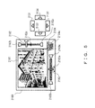
- FIG. 8 is a first view that explains an example of a calculation method of eight projection transform parameters
- FIG. 9 is a second view that explains an example of the calculation method of eight projection transform parameters
- FIG. 10 is a third view that explains an example of the calculation method of eight projection transform parameters
- FIG. 11 is a flowchart showing an example of a focus bracket photography process
- FIG. 12 explains an example of a calculation method of a focus movement range
- FIG. 13 is a first view that explains an example of a depth synthesization process
- FIG. 14 is a second view that explains an example of the depth synthesization process
- FIG. 15 is a flowchart showing a modification example of operations of the camera according to an embodiment
- FIG. 16 is a flowchart showing another modification example of operations of the camera according to an embodiment
- FIG. 17 shows an example in which tilt photography is performed
- FIG. 18 shows an example in which a tilt-distortion correction is performed on an image that was obtained through tilt photography
- FIG. 19 shows an example in which photography is performed by a camera having a lens shift mechanism
- FIG. 20 shows an example of an image obtained by a camera having a lens shift mechanism.
- FIG. 1 shows a configuration example of a camera, which is an imaging device according to an embodiment of the present invention.
- this camera is an interchangeable lens camera, it may be a camera with a fixed lens.
- the camera 1 has an interchangeable lens 10 and a camera body 20 , and is configured so that the interchangeable lens 10 is removable from the camera body 20 .
- the interchangeable lens 10 and the camera body 20 can perform communications via an I/F (interface) 30 .
- the I/F 30 is configured to connect for example electric contacts that are provided to the interchangeable lens 10 and the camera body 20 , when the interchangeable lens 10 is mounted on the camera body 20 .
- the interchangeable lens 10 includes a photography lens 101 , a diaphragm 102 , a driver 103 , a microcomputer 104 and a flash memory 105 .
- the photography lens 101 is an optical system for condensing a light flux coming from the subject (not shown) to an image sensor 202 in the camera body 20 , and includes a focusing lens.
- the photography lens 101 may include a zoom lens.
- the diaphragm 102 is configured to open and close freely so as to adjust the amount of the light flux entering through the photography lens 101 .
- the driver 103 has a motor etc., and is a driving mechanism that, under control of the microcomputer 104 , drives (moves) the focusing lens in the photography lens 101 in its optical axial directions and opens and closes the diaphragm 102 .
- the microcomputer 104 executes a program stored in the flash memory 105 so as to control operations of the interchangeable lens 10 .
- the microcomputer 104 performs, under control of a microcomputer 211 in the camera body 20 , driving control of the focusing lens in the photography lens 101 , the open-close driving control of the diaphragm 102 , etc. during focus bracket photography, which will be described later.
- the flash memory 105 stores a program executed by the microcomputer 104 , data used for the execution of that program, etc.
- the camera body 20 includes a mechanical shutter 201 , an image sensor 202 , an analog process unit 203 , an A/D (Analog/Digital) conversion unit 204 , an image process unit 205 , a tilt-distortion correction unit 206 , a depth synthesization process unit 207 , an AE (Auto Exposure) process unit 208 , an AF (Auto Focus) process unit 209 , a JPEG (Joint Photographic Experts Group) process unit 210 , a microcomputer 211 , a flash memory 212 , a manipulation unit 213 , an SDRAM (Synchronous Dynamic Random Access Memory) 214 , a memory I/F 215 , a recording medium 216 , a monitor driver 217 , a monitor 218 and a bus 219 .
- the mechanical shutter 201 is configured to move freely so as to bring the photoelectric conversion plane of the image sensor 202 into a light-blocked state or an exposed state. By moving this mechanical shutter 201 , the exposure time of the image sensor 202 is adjusted. Note that the mechanical shutter 201 is for example a focal plane shutter.
- the image sensor 202 has a photoelectric conversion plane on which a light flux from the subject that was condensed by the photography lens 101 is formed.
- the photoelectric conversion plane includes a plurality of pixels that are arranged in two dimensions.
- the light-entering side of the photoelectric conversion plane has a color filter in for example a Bayer array.
- This image sensor 202 converts an image (subject image) corresponding to the light flux formed on the photoelectric conversion plane into an electric signal corresponding to the light amount of the light flux (which will be referred to as an image signal hereinafter) in order to output the resultant signal.
- the image sensor 202 picks up the subject image formed on the photoelectric conversion plane so as to output an image signal corresponding to the subject image.
- the image sensor 202 has an electronic shutter function that controls the exposure time electronically.
- the image sensor 202 is for example an image sensor such as a CCD (Charge Coupled Device), a CMOS (Complementary Metal Oxide Semiconductor), etc.
- the analog process unit 203 performs an analog process such as a CDS (Correlated Double Sampling) process, an AGC (Automatic Gain Control) process, etc. on an image signal output from the image sensor 202 .
- an analog process such as a CDS (Correlated Double Sampling) process, an AGC (Automatic Gain Control) process, etc.
- the A/D conversion unit 204 converts an image signal that received an analog process by the analog process unit 203 into a digital signal (which will be referred to as RAW image data hereinafter). Note that RAW image data is “raw” image data before receiving an image process by the image process unit 205 .
- the analog process unit 203 and the A/D conversion unit 204 function as a signal converter that converts an image signal output from the image sensor 202 into image data.
- the image process unit 205 performs various types of image processes on RAW image data so as to generate to-be-recorded image data (such as focus bracket image data) or to-be-displayed image data (such as live view image data). Note that different parameters were used in the image processes between to-be-recorded image data and to-be-displayed image data.
- the image process unit 205 includes a synchronization process unit 2051 , an edge enhancement process unit 2052 , a noise reduction process unit 2053 and a distortion correction process unit 2054 .
- the synchronization process unit 2051 converts image data, such as RAW image data etc. output via the image sensor 202 and corresponding to for example a Bayer array, in which one pixel corresponds to one color component into RGB image data in which one pixel corresponds to a plurality of color components.
- the edge enhancement process unit 2052 extracts a plurality of frequency component signals (edge signals) from RGB image data so as to correct the frequency characteristic of each of the extracted edge signals.
- the noise reduction process unit 2053 using a coring process etc., removes noise components in RGB image data.
- the distortion correction process unit 2054 corrects distortion based on the distortion aberration of the photography lens 101 in the RGB image data.
- to-be-recorded image data or to-be-displayed image data generated by the image process unit 205 is also RGB image data after receiving the processes by the respective process units in the image process unit 205 .
- the tilt-distortion correction unit 206 performs a tilt-distortion correction in accordance with the set tilt-distortion correction level so as to correct distortion of the subject in the image represented by the image data.
- the tilt-distortion correction unit 206 performs a tilt-distortion correction so as to correct distortion of the subject in the live view image represented by the live view image data and distortion of the subject in the image represented by synthesis image data generated by the depth synthesization process unit 207 . Note that this distortion of the subject is caused when the image projection plane of the camera 1 is tilted with respect to the subject as shown in for example FIG. 17 .
- the depth synthesization process unit 207 performs a depth synthesization process so as to generate, from a plurality of pieces of focus bracket image data obtained through the focus bracket photography process etc., a synthesis image data that represents an image in which the entire subject is in focus.
- the AE process unit 208 calculates the subject brightness by using image data (such as RAW image data). Note that the subject brightness may be measured by for example a dedicated photometric sensor.
- the AF process unit 209 extracts signals of a high-frequency component from image data (such as RAW image data) and integrates the extracted signals of high-frequency component so as to obtain a focus evaluation value for AF.
- the JPEG process unit 210 performs a JPEG compression process on image data and a JPEG decompression process on image data that received a JPEG compression process.
- the microcomputer 211 executes a program stored in the flash memory 212 so as to control operations of the camera 1 (interchangeable lens 10 and the camera body 20 ). For example, the microcomputer 211 controls operations shown in FIG. 2 , which will be described later.
- the flash memory 212 stores a program executed by the microcomputer 211 , data used for the execution of that program, etc.
- the manipulation unit 213 corresponds to various types of manipulation members manipulated by the user.
- the manipulation unit 213 includes up-arrow, down-arrow, left-arrow and right-arrow buttons, a release button, a play button, a menu button, a power button, etc.
- the up-arrow, down-arrow, left-arrow and right-arrow buttons are used for inputting setting instructions for the tilt-distortion correction level by the user, as will be described later by referring to FIG. 5 .
- the release button is a two-step button having a halfway-pressed (first release) mode and a fully-pressed (second release) mode, and is used for inputting a photography preparation instruction and a photography instruction by the user.
- the play button is used for inputting a play instruction by the user.
- the menu button is used for inputting a menu window display instruction by the user.
- the power button is used for inputting turn-on/turn-off instructions by the user. Note that some or all of these buttons may be configured as a virtual manipulation unit that is manipulated through a touch panel.
- the SDRAM 214 is a memory used as a working area etc., and temporarily stores for example data that is being processed (such as image data or other data).
- the memory I/F 215 is an interface used by the microcomputer 211 etc. for accessing the recording medium 216 .
- the recording medium 216 is a memory card that is detachable from the camera body 20 .
- This recording medium 216 records an image file etc.
- An image file is a file obtained by for example adding header information to image data that received JPEG compression by the JPEG process unit 210 .
- the recording medium 216 may be embedded in the camera body 20 (does not have to be detachable).
- the monitor driver 217 is for example a display driver IC (Integrated Circuit), and converts image data (such as live view image data that received a tilt-distortion correction) into an image signal so as to output the image signal to the monitor 218 .
- image data such as live view image data that received a tilt-distortion correction
- the monitor 218 is for example a liquid crystal display (LED) panel, and displays an image (such as a live view image that received a tilt-distortion correction) in accordance with an image signal input from the monitor driver 217 .
- an image such as a live view image that received a tilt-distortion correction
- the bus 219 is a transfer line for transferring various types of pieces of data in the camera body 20 .
- At least the focusing lens, the image sensor 202 , the analog process unit 203 and the A/D conversion unit 204 are examples of an imaging unit that outputs image data.
- the manipulation unit 213 is an example of an input unit that inputs the tilt-distortion correction level.
- the tilt-distortion correction unit 206 is an example of a tilt-distortion correction image generation unit that generates tilt-distortion correction image data in accordance with the tilt-distortion correction level.
- the monitor 218 is an example of a display panel that displays the tilt-distortion correction image represented by the tilt-distortion correction image data.
- the function of part of the microcomputer 211 is an example of the live-view controller that repeatedly issues a series of instructions for making the imaging unit output image data, making the tilt-distortion correction image generation unit generate tilt-distortion correction image data on the basis of the image data, and making the display panel display the tilt-distortion correction image represented by the tilt-distortion correction image data.
- the function of different parts of the microcomputer 211 is an example of a focus bracket controller that instructs the focusing lens to move to each of a plurality of lens positions determined on the basis of the tilt-distortion correction level and that instructs the imaging unit to output image data when the focusing lens has moved to each of the plurality of lens positions.
- the analog process unit 203 , the A/D conversion unit 204 , the image process unit 205 , the tilt-distortion correction unit 206 , the depth synthesization process unit 207 , the AE process unit 208 , the AF process unit 209 and the JPEG process unit 210 for example are realized by electronic circuits such as an ASIC (Application Specific Integrated Circuit), an FPGA (Field Programmable Gate Array), etc.
- ASIC Application Specific Integrated Circuit
- FPGA Field Programmable Gate Array
- FIG. 2 is a flowchart showing an example of operations of the camera 1 .
- the microcomputer 211 first initializes the respective units of the camera 1 (S 101 ).
- the microcomputer 211 determines whether or not the play button included in the manipulation unit 213 has been pressed (S 102 ).
- the microcomputer 211 When the determination result is YES in S 102 , the microcomputer 211 performs playing of an image file (image data) recorded in the recording medium 216 , editing of that image data, etc. in accordance with the manipulations on the manipulation unit 213 (S 103 ). When the determination result is NO in S 102 , S 103 is skipped.
- the microcomputer 211 determines whether or not a manipulation for a camera setting has been performed on the manipulation unit 213 (S 104 ).
- the microcomputer 211 performs camera setting in accordance with the manipulation on the manipulation unit 213 (S 105 ).
- the user can conduct setting of the tilt-distortion correction mode, the tilt-distortion correction level, the RAW recording mode, etc.
- the setting of the tilt-distortion correction level can be performed after the tilt-distortion correction mode is set. The method of setting the tilt-distortion correction level will be described later by referring to FIG. 5 .
- S 105 is skipped.
- the tilt-distortion correction mode is set in S 105 after S 104 in which the determination result is YES, and explanations will be given for the process after S 105 . Note that when the tilt-distortion correction mode has been set, the subsequent processes are performed on an assumption that the user will conduct tilt photography.
- the microcomputer 211 determines whether or not the release button included in the manipulation unit 213 has transitioned from the off state (the state in which it is not pressed) to a first release state (halfway-pressed state) (S 106 ).
- the microcomputer 211 performs the AE process and the AF process, which are photography preparation processes (S 107 ).
- the microcomputer 211 makes the AE process unit 208 calculate the subject brightness so as to determine the ISO sensitivity, the F-number, and the shutter speed for the execution of a photography process in accordance with that subject brightness.
- the microcomputer 211 makes the AF process unit 209 obtain the focus evaluation value and instructs the microcomputer 104 to drive the focusing lens in the photography lens 101 by a short distance at a time while evaluating the contrast on the basis of that focus evaluation value.
- the microcomputer 211 instructs the microcomputer 104 to stop the driving of the focusing lens.
- An AF process as described above is an AF process based on a so-called contrast method. Note that a phase difference AF process may be performed as the AF process. Also, in this AF process, the SDRAM 214 for example stores information related to an image focus position, which indicates what position is in focus in the image.
- the microcomputer 211 determines whether or not the power button included in the manipulation unit 213 has been pressed (S 108 ).
- the power of the camera is turned off so as to terminate the present operation. Note that in the camera 1 , when the power button is pressed with the power of the camera in an off state, the power of the camera is turned off.
- the determination result is NO in S 108 , the process returns to S 102 .
- the microcomputer 211 determines whether or not the release button included in manipulation unit 213 has transitioned to a second state (fully-pressed state) (S 109 ).
- the case where the determination result is NO in S 106 is a case where the release button is in an off state or a case where the release button has transitioned from an off state to a first release state and the first release state is thereafter maintained.
- the microcomputer 211 starts processes for live view display (S 110 through S 114 ).
- the microcomputer 211 first performs a photography process using an electronic shutter (the electronic shutter function of the image sensor 202 ) (S 110 ).
- the microcomputer 211 makes the image sensor 202 perform imaging, makes the analog process unit 203 perform an analog process, and makes the A/D conversion unit 204 perform an A/D conversion and output RAW image data.
- the microcomputer 211 makes the image process unit 205 perform an image process on that RAW image data and generate live view image data (S 111 ).
- the microcomputer 211 makes the tilt-distortion correction unit 206 perform, on that live view image data, a tilt-distortion correction in accordance with the set tilt-distortion correction level (S 112 ).
- the microcomputer 211 superimposes a GUI (Graphical User Interface) on the live view image data (an example of tilt-distortion correction image data) on which that tilt-distortion correction was performed (S 113 ).
- GUI Graphic User Interface
- the GUI is for example a slide bar, an icon, etc., which will be described later by referring to FIG. 5 .
- the microcomputer 211 makes the monitor 218 display a live view image represented by the live view image data on which that GUI is superimposed (S 114 ).
- the microcomputer 211 starts processes for recording a still image (S 115 through S 121 ).
- the microcomputer 211 first performs a focus bracket photography process (S 115 ).
- this focus bracket photography process the focusing lens in the photography lens 101 moves to a plurality of different lens positions and a photography process is performed at each of the lens positions so that a plurality of pieces of RAW image data are obtained, as will be explained later in detail by referring to FIG. 11 .
- the microcomputer 211 determines whether or not the RAW recording mode is set (S 116 ).
- the microcomputer 211 records, in the recording medium 216 , a plurality of pieces of RAW image data obtained in S 115 (S 117 ).
- S 117 is skipped.
- the microcomputer 211 makes the image process unit 205 perform an image process on each of the plurality of pieces of RAW image data obtained in S 115 and generate a plurality of pieces of focus bracket image data (S 118 ).
- the microcomputer 211 makes the depth synthesization process unit 207 perform a depth synthesization process on the plurality of pieces of focus bracket image data and generate synthesis image data that represents an image in which the entire subject is in focus (S 119 ).
- the microcomputer 211 makes the tilt-distortion correction unit 206 perform a tilt-distortion correction on the synthesis image data in accordance with the set tilt-distortion correction on the basis of the set tilt-distortion correction level (S 120 ).
- the microcomputer 211 records, in the recording medium 216 , the synthetic image data (an example of tilt-distortion correction image data) on which that tilt-distortion correction was performed (S 121 ). However, when a plurality of pieces of RAW image data were recorded in S 117 , the synthetic image data on which the tilt-distortion correction was performed is recorded in association with the plurality of pieces of RAW image data.
- FIG. 3 and FIG. 4 schematically show an example of S 115 through S 121 (processes for recording a still image).
- a focus bracket photography process first moves the focusing lens in the photography lens 101 to each of a plurality of different lens positions, and a photography process is performed at each of the lens positions so that a plurality of pieces of RAW image data are obtained.
- an image process is performed on each of the plurality of pieces of RAW image data so that a plurality of pieces of focus bracket image data are generated.
- the focus bracket image represented by each of the plurality of pieces of focus bracket image data is an image in which part of the subject is out of focus.
- a depth synthesization process generates a synthetic image data that represents an image in which the entire subject is in focus.
- the image represented by that synthetic image data is an image in which the entire subject is in focus.
- a tilt-distortion correction is performed on that synthetic image data.
- the image represented by the synthetic image data after the tilt-distortion correction is an image equivalent to a photography image obtained by the effect of the lens shift mechanism explained by referring to FIG. 19 and FIG. 20 (an image not involving distortion of the subject and having the entire subject in focus).
- FIG. 5 shows a monitor window example displayed in the monitor 218 when the tilt-distortion correction level is set in S 105 above (S 105 that is performed after S 114 ).
- a monitor window 2180 then displays slide bars 2182 , 2183 and an image shape 2184 after receiving the tilt-distortion correction, etc., together with a live view image 2181 after receiving the tilt-distortion correction in accordance with the tilt-distortion correction level set at that moment.
- the slide bar 2182 is used for setting the tilt-distortion correction level in the vertical directions of the image.
- This slide bar 2182 moves upward and downward in accordance with the manipulations of an up-arrow button 2131 and a down-arrow button 2132 included in the manipulation unit 213 , and the tilt-distortion correction level in the vertical directions of the image is set in accordance with the movement amount of the slide bar 2182 from a center position 2182 a .
- the tilt-distortion correction level in the vertical directions of the image is set to be zero, and with an increasing movement amount of the slide bar 2182 from the center position 2182 a , the tilt-distortion correction level is set to be higher in the movement direction. Note that when the tilt-distortion correction level is set to zero, a tilt-distortion correction will not be performed. Also, a tilt-distortion correction level that has been set to be too high increases the degree of the tilt-distortion correction and a tilt-distortion correction level that has been set to be too low decreases the degree of the tilt-distortion correction.
- An icon 2182 b displayed on the upper side of the slide bar 2182 displays the tendency of an image shape after receiving a tilt-distortion correction in a case when the slide bar 2182 has moved upward from the center position 2182 a .
- An icon 2182 c displayed on the lower side of the slide bar 2182 displays the tendency of the image shape after receiving a tilt-distortion correction in a case when the slide bar 2182 has moved downward from the center position 2182 a.
- the slide bar 2183 is used for setting a tilt-distortion correction level in the horizontal directions of the image.
- This slide bar 2183 moves leftward and rightward in accordance with the manipulations of the left-arrow button 2133 and the right-arrow button 2134 included in the manipulation unit 213 , and the tilt-distortion correction level in the horizontal directions of the image is set in accordance with the movement amount of the slide bar 2183 from a center position 2183 a (which is depicted by dashed lines because it overlaps the slide bar 2183 in FIG. 5 ).
- the tilt-distortion correction level in the horizontal directions of the image is set to be zero, and with an increasing movement amount of the slide bar 2183 from the center position 2183 a , the tilt-distortion correction level is set to be higher in the movement direction.
- An icon 2183 b displayed on the left side of the slide bar 2183 displays the tendency of an image shape after receiving a tilt-distortion correction in a case when the slide bar 2183 has moved leftward from the center position 2183 a .
- An icon 2183 c displayed on the right side of the slide bar 2183 displays the tendency of an image shape after receiving a tilt-distortion correction in a case when the slide bar 2183 has moved rightward from the center position 2183 a.
- the image shape 2184 after the tilt-distortion correction represents an image shape after receiving the tilt-distortion correction in accordance with the tilt-distortion correction level set at that moment.
- a rectangle 2184 a in the image shape 2184 represents an area used for recording or displaying an image.
- FIG. 6 schematically shows an example of a tilt-distortion correction table used when a tilt-distortion correction is performed in the processes in S 112 and S 120 described above. Note that this tilt-distortion correction table is stored in for example the flash memory 212 .
- the tilt-distortion correction table stores “type”, “tilt angle” and “projection transform formula” of tilt-distortion corrections corresponding to the tilt-distortion correction levels set in response to movements of the slide bar 2182 or the slide bar 2183 shown in FIG. 5 .
- “Type” of a tilt-distortion correction corresponds to the icons 2182 b , 2182 c , 2183 b and 2183 c shown in FIG. 5 .
- “Tilt angle” is a tilt angle that is to be corrected.
- “Projection transform formula” is a projection transform formula used for a tilt-distortion correction.
- x and y are coordinates before a tilt-distortion correction and X and Y are coordinates after a tilt-distortion correction.
- a, b, c, d, e, f, g, and h are projection transform parameters.
- a projection transform formula corresponding to a set tilt-distortion correction level is selected from the above tilt-distortion correction table, a tilt-distortion correction is performed by using that projection transform formula, and tilt-distortion correction image data is generated.
- FIG. 7 shows an example of coordinates before and after a tilt-distortion correction.
- coordinates p (x i ,y j ) in an image 41 before receiving a tilt-distortion correction will become for example coordinates q (X i ,Y j ) after receiving a tilt-distortion correction.
- P x represents the length in the horizontal directions (corresponding to the number of pixels in the horizontal directions) of the image 41 and P y represents the length in the vertical directions (corresponding to the number of pixels in the horizontal directions) of the image 41 .
- an image 41 ′ which is enclosed by the dashed line, represents an image after a tilt-distortion correction and an area 42 , enclosed by the sold line, in the image 41 ′ represents an area that is used for recording or displaying an image.
- FIG. 8 through FIG. 10 explain an example of a calculation method of the above eight projection transform parameters. Note that FIG. 9 shows plane A of FIG. 8 seen from above.
- tilt photography was performed by using the camera 1 at tilt angle ⁇ with respect to the horizontal directions and a tilt-distortion correction is to be performed on tilt angle ⁇ .
- tilt angle ⁇ corresponds to a tilt angle stored in the tilt-distortion correction table.
- ⁇ represents a photography angle of field, and is obtained by equation (2) below.
- h represents the size in the vertical directions of the image sensor 202 and F represents a focal length.
- upper side length W′ of the image projection plane 52 after a tilt-distortion correction with respect to upper side length W of the image projection plane 51 before a tilt-distortion correction is obtained by equation (3) below.
- the upper side length (horizontal length) P x and vertical length P y of the image 41 before a tilt-distortion correction are represented by (W′/W) ⁇ P x and (H′/H) ⁇ P y in the image 41 ′ after a tilt-distortion correction.
- the above eight projection transform parameters can be obtained from a simultaneous equation consisting of eight equations on the basis of the positional relationships between the four vertex coordinates of the image 41 before a tilt-distortion correction and the four vertex coordinates of the image 41 ′ after a tilt-distortion correction.
- FIG. 11 is a flowchart showing an example of the focus bracket photography process in S 115 above.
- the microcomputer 211 calculates a focus movement range (corresponding to a movement range of the focusing lens in the photography lens 101 ), which will be described later by referring to FIG. 12 (S 201 ).
- the microcomputer 211 sets a focus movement step (corresponding to a movement step of a focusing lens) on the basis of the diaphragm etc. during the photography process (S 202 ). It is desired that this focus movement step be an interval narrower than the range of a depth of field that is determined by the state, such as the diaphragm etc., of the interchangeable lens 10 and the pixel pitch (permissible circle of confusion).
- the microcomputer 211 performs a photography process on each of a plurality of focus positions such as the nearest-side focus position and the farthest-side focus position in the focus movement range calculated in S 201 and the focus position for each focus movement step set in S 202 (S 203 through S 205 ).
- the microcomputer 211 first selects one of the above plurality of focus positions as a process target focus position, moves the focusing lens to the lens position corresponding to the process target focus position, and performs a photography process (S 203 ).
- the microcomputer 211 makes the image sensor 202 perform an imaging process, makes the analog process unit 203 perform an analog process, and makes the A/D conversion unit 204 perform an A/D conversion and output RAW image data.
- the microcomputer 211 determines whether or not the photography processes on all focus positions have been terminated (whether or not all focus positions became process target focus positions) (S 204 ).
- the microcomputer 211 changes a process target focus position (treats, as a new process target focus position, a focus position that has not become a process target focus position) (S 205 ), and the process returns to S 203 .
- FIG. 12 explains an example of a calculation method of the above focus movement range.
- ⁇ represents a photography angle of field, and is obtained by equation (2) above.
- ⁇ represents a tilt angle
- D o represents a subject distance of the AF focus point (focus point upon the AF process in S 107 above).
- H f is the image height of an AF focus point, and is obtained by equation (4) below.
- y f represents the y coordinate (y coordinate of the image focus position represented by information on an image focus position stored in the SDRAM 214 in the AF process in S 107 above) of the AF focus point in the image.
- P y is the vertical length of the image as described above.
- the focus movement range is represented as a range resulting from adding D S and D L by referring to the subject position at subject distance D 0 shown in FIG. 12 .
- D S is a range of nearest-side subject distances, and is obtained by equation (5).
- D L is a range of farthest-side subject distances, and is obtained by equation (6) below.
- the lens position of the focusing lens corresponding to Do can also be treated as a reference position for determining the plurality of lens positions described above.
- FIG. 13 and FIG. 14 explain an example of the depth synthesization process in S 119 above.
- photography image 0 “photography image 1 ”, “photography image 2 ”, “photography image 3 ” and “photography image 4 ” are images represented by a plurality of pieces of focus bracket image data that are targets of a depth synthesization process.
- D 0 is the subject distance when the image data representing “photography image 0 ” is obtained.
- D 1 is the subject distance when the image data representing “photography image 1 ” is obtained.
- D 2 is the subject distance when the image data representing “photography image 2 ” is obtained.
- D 3 is the subject distance when the image data representing “photography image 3 ” is obtained.
- D 4 is the subject distance when the image data representing “photography image 4 ” is obtained.
- ⁇ is a photography angle of field, and is obtained by equation (2) above. ⁇ represents a tilt angle.
- the pieces of image data representing the respective photography images receive weighted synthesization in accordance with the image positions (image Y coordinates in the present example) in the photography images so that synthetic image data representing an image in which the entire subject is in focus is obtained.
- this weighted synthesization assigns weights 0 through 1 to the respective pixels in the y directions of each photography image as shown in FIG. 13 .
- 1 through 0 are assigned as the weights of “photography image 0 ”
- 0 through 1 are assigned as the weights of “photography image 1 ”
- ⁇ is assigned as the weights of the other photography images.
- 1 through 0 are assigned as the weights of “photography image 1 ”
- 0 through 1 are assigned as the weights of “photography image 2 ”
- 0 is assigned as the weights of the other photography images.
- y 1 , y 2 and y 3 are obtained by the equation (7) below.
- a general depth synthesization process (for example the process described in Japanese Laid-open Patent Publication No. 2008-271240) may be employed.
- a general depth synthesization process will result in an image in which all portions of the image are in focus (for example an image in which not only the building but also the other portions are in focus).
- an image equivalent to a photography image obtained by the effect of the lens shift mechanism explained in FIG. 19 and FIG. 20 is desired, it is better to adopt the depth synthesization process explained by FIG. 13 and FIG. 14 .
- the present embodiment performs a tilt-distortion correction in accordance with a tilt-distortion correction level set by the user so that the user can obtain an image in which the entire subject is in focus just by the user performing photography after adjusting the tilt-distortion correction level while looking at the live view image. Also, because a plurality of focus positions in a focus bracket photography process performed then are automatically determined by the camera 1 without the necessity of particular manipulations performed by the user, the user does not have to pay attention to the depth range of the subject etc. while performing photography.
- the operations of the camera 1 shown in FIG. 2 may be modified as follows.
- FIG. 15 is a flowchart showing a modification example of operations of the camera 1 .
- the present modification example performs a depth synthesization process (S 131 ) after the microcomputer 211 performs the focus bracket photography process (S 115 ).
- the microcomputer 211 makes the depth synthesization process unit 207 perform a depth synthesization process on a plurality of pieces of RAW image data obtained in the focus bracket photography process so that synthetic RAW image data that represents an image in which the entire subject is in focus is generated.
- the microcomputer 211 determines whether or not the RAW recording mode is set (S 132 ).
- the microcomputer 211 records, in the recording medium 216 , synthetic RAW image data generated in S 131 (S 133 ).
- S 133 is skipped.
- the microcomputer 211 makes the image process unit 205 perform an image process on the synthetic RAW image data generated in S 131 so that to-be-recorded image data is generated (S 134 ).
- the microcomputer 211 makes the tilt-distortion correction unit 206 perform a tilt-distortion correction in accordance with the set tilt-distortion correction level on that to-be-recorded image data (S 135 ).
- the microcomputer 211 records, in the recording medium 216 , the to-be-recorded image data that received the tilt-distortion correction (S 136 ). However, when synthetic RAW image data has been recorded in S 133 , the image data that received the tilt-distortion correction is recorded in association with that piece of synthetic RAW image data.
- FIG. 15 The other processes shown in FIG. 15 are similar to those shown in FIG. 2 .
- this modification example may be configured to further allow the user to edit the synthetic RAW image data recorded in the recording medium 216 in S 103 in FIG. 15 . In such a case, it may be possible to permit a tilt-distortion correction in accordance with a desired tilt-distortion correction level as editing of synthetic RAW image data.
- FIG. 16 is a flowchart showing another modification example of operations performed by the camera 1 .
- the microcomputer 211 determines whether or not the interchangeable lens 10 is a corresponding lens and that point in time is a point in time after the execution of the AF process in S 107 (S 141 ).
- a corresponding lens is an interchangeable lens that is configured to be able to move the focusing lens at high speeds.
- the microcomputer 211 starts the processes for different live view displays (S 142 through S 148 ).
- the microcomputer 211 first changes the set diaphragm condition by for example increasing the F-number or by performing other operations so that the depth of field becomes greater (S 142 ).
- the microcomputer 211 performs a focus bracket photography process (S 143 ). While the focus bracket photography process performed then is as shown in FIG. 11 , because the diaphragm condition has been set so that the depth of field becomes greater in S 142 , a greater value is set as the focus movement step in S 202 in FIG. 11 . This reduces the number of photography processes in the focus bracket photography process, leading to a smaller number of pieces of RAW image data that are obtained.
- the microcomputer 211 makes the image process unit 205 perform an image process on each of a plurality of pieces of RAW image data obtained in S 143 so as to generate a plurality of pieces of live view image data (S 144 ).
- the microcomputer 211 makes the depth synthesization process unit 207 perform a depth synthesization process on those plurality of pieces of live view image data so as to generate synthetic live view image data of an image in which the entire subject is in focus (S 145 ).
- the microcomputer 211 makes the tilt-distortion correction unit 206 perform a tilt-distortion correction in accordance with a set tilt-distortion correction level on that synthetic live view image data (S 146 ).
- the microcomputer 211 superimposes a GUI (a GUI similar to that in S 113 ) on the synthetic live view image data on which that tilt-distortion correction was performed (S 147 ).
- the microcomputer 211 makes the monitor 218 display a synthetic live view image represented by the synthetic live view image data on which that GUI has been superimposed (S 148 ).
- FIG. 16 The other processes shown in FIG. 16 are similar to those in FIG. 2 .
- the modification example as described above makes it possible to make the monitor 218 display a live view image that is an image in which the entire subject is in focus and that is an image on which a tilt-distortion correction has been performed, when the determination result is YES in S 141 .
- the process in S 142 may also be omitted in this modification example when there is no possibility of process delay.
- a tilt-distortion correction may be performed in accordance with a tilt detected by a sensor by for example providing a sensor for detecting the tilt of the camera 1 (for example a gyro sensor) to the camera 1 .
Landscapes
- Engineering & Computer Science (AREA)
- Multimedia (AREA)
- Signal Processing (AREA)
- Computing Systems (AREA)
- Theoretical Computer Science (AREA)
- Human Computer Interaction (AREA)
- Studio Devices (AREA)
- Details Of Cameras Including Film Mechanisms (AREA)
- Lens Barrels (AREA)
- Image Processing (AREA)
Applications Claiming Priority (2)
| Application Number | Priority Date | Filing Date | Title |
|---|---|---|---|
| JP2016109247A JP6644641B2 (ja) | 2016-05-31 | 2016-05-31 | 撮像装置、制御方法、及びプログラム |
| JP2016-109247 | 2016-05-31 |
Publications (2)
| Publication Number | Publication Date |
|---|---|
| US20170347031A1 US20170347031A1 (en) | 2017-11-30 |
| US10158804B2 true US10158804B2 (en) | 2018-12-18 |
Family
ID=60418627
Family Applications (1)
| Application Number | Title | Priority Date | Filing Date |
|---|---|---|---|
| US15/588,501 Active 2037-05-23 US10158804B2 (en) | 2016-05-31 | 2017-05-05 | Imaging device, control method and recording medium having stored program |
Country Status (2)
| Country | Link |
|---|---|
| US (1) | US10158804B2 (enExample) |
| JP (1) | JP6644641B2 (enExample) |
Families Citing this family (5)
| Publication number | Priority date | Publication date | Assignee | Title |
|---|---|---|---|---|
| WO2018045592A1 (zh) * | 2016-09-12 | 2018-03-15 | 华为技术有限公司 | 拍摄图像方法、装置和终端 |
| KR102473840B1 (ko) * | 2017-11-21 | 2022-12-05 | 삼성전자주식회사 | 디스플레이 드라이버 및 모바일 전자 기기 |
| EP3748283B1 (en) * | 2018-01-31 | 2025-01-01 | FUJIFILM Corporation | Repair length determination method and repair length determination device |
| JP7184654B2 (ja) * | 2019-01-10 | 2022-12-06 | i-PRO株式会社 | 撮影装置、画像補正方法、および画像補正プログラム |
| JP6679779B1 (ja) * | 2019-03-01 | 2020-04-15 | キヤノン株式会社 | 情報処理装置、情報処理方法およびプログラム |
Citations (13)
| Publication number | Priority date | Publication date | Assignee | Title |
|---|---|---|---|---|
| JP2000013665A (ja) | 1998-06-19 | 2000-01-14 | Fuji Photo Film Co Ltd | 電子カメラおよびその制御方法 |
| US20020118292A1 (en) * | 2001-02-28 | 2002-08-29 | Baron John M. | System and method for removal of digital image vertical distortion |
| JP2003348430A (ja) | 2002-05-27 | 2003-12-05 | Nikon Corp | 電子カメラ、画像処理装置、画像処理プログラム、および画像処理方法 |
| JP2008271240A (ja) | 2007-04-20 | 2008-11-06 | Fujifilm Corp | 撮像装置、画像処理装置、撮像方法、及び画像処理方法 |
| US20100128163A1 (en) * | 2008-11-25 | 2010-05-27 | Sony Corporation | Imaging device and imaging method |
| JP2010210671A (ja) | 2009-03-06 | 2010-09-24 | Hoya Corp | アオリ撮影方法及びアオリ撮影可能なカメラ |
| JP2011041092A (ja) | 2009-08-13 | 2011-02-24 | Nikon Corp | 撮像装置及びレンズ鏡筒 |
| US20150138383A1 (en) * | 2013-11-21 | 2015-05-21 | International Business Machines Corporation | Automated tilt and shift optimization |
| US9294679B1 (en) * | 2014-11-26 | 2016-03-22 | Visual Supply Company | Real-time perspective correction |
| US20160112652A1 (en) * | 2013-07-04 | 2016-04-21 | Sony Corporation | Method, apparatus and system for image processing |
| US20160205308A1 (en) * | 2015-01-09 | 2016-07-14 | Canon Kabushiki Kaisha | Display apparatus, image capturing apparatus, image capturing system, control method for display apparatus, control method for image capturing apparatus, and storage medium |
| US20170078577A1 (en) * | 2015-09-15 | 2017-03-16 | Canon Kabushiki Kaisha | Image-blur correction apparatus, tilt correction apparatus, method of controlling image-blur correction apparatus, and method of controlling tilt correction apparatus |
| US20170352132A1 (en) * | 2014-12-22 | 2017-12-07 | Zte Corporation | Method and apparatus for correcting tilt of subject ocuured in photographing, mobile terminal, and storage medium |
Family Cites Families (3)
| Publication number | Priority date | Publication date | Assignee | Title |
|---|---|---|---|---|
| JP5747474B2 (ja) * | 2010-10-29 | 2015-07-15 | カシオ計算機株式会社 | 撮像装置、撮像処理方法及びプログラム |
| JP6486603B2 (ja) * | 2014-04-03 | 2019-03-20 | シャープ株式会社 | 画像処理装置 |
| JP6320251B2 (ja) * | 2014-09-09 | 2018-05-09 | オリンパス株式会社 | 撮像装置、撮像方法、およびプログラム |
-
2016
- 2016-05-31 JP JP2016109247A patent/JP6644641B2/ja not_active Expired - Fee Related
-
2017
- 2017-05-05 US US15/588,501 patent/US10158804B2/en active Active
Patent Citations (14)
| Publication number | Priority date | Publication date | Assignee | Title |
|---|---|---|---|---|
| JP2000013665A (ja) | 1998-06-19 | 2000-01-14 | Fuji Photo Film Co Ltd | 電子カメラおよびその制御方法 |
| US20020118292A1 (en) * | 2001-02-28 | 2002-08-29 | Baron John M. | System and method for removal of digital image vertical distortion |
| JP2003348430A (ja) | 2002-05-27 | 2003-12-05 | Nikon Corp | 電子カメラ、画像処理装置、画像処理プログラム、および画像処理方法 |
| US8023000B2 (en) | 2007-04-20 | 2011-09-20 | Fujifilm Corporation | Image pickup apparatus, image processing apparatus, image pickup method, and image processing method |
| JP2008271240A (ja) | 2007-04-20 | 2008-11-06 | Fujifilm Corp | 撮像装置、画像処理装置、撮像方法、及び画像処理方法 |
| US20100128163A1 (en) * | 2008-11-25 | 2010-05-27 | Sony Corporation | Imaging device and imaging method |
| JP2010210671A (ja) | 2009-03-06 | 2010-09-24 | Hoya Corp | アオリ撮影方法及びアオリ撮影可能なカメラ |
| JP2011041092A (ja) | 2009-08-13 | 2011-02-24 | Nikon Corp | 撮像装置及びレンズ鏡筒 |
| US20160112652A1 (en) * | 2013-07-04 | 2016-04-21 | Sony Corporation | Method, apparatus and system for image processing |
| US20150138383A1 (en) * | 2013-11-21 | 2015-05-21 | International Business Machines Corporation | Automated tilt and shift optimization |
| US9294679B1 (en) * | 2014-11-26 | 2016-03-22 | Visual Supply Company | Real-time perspective correction |
| US20170352132A1 (en) * | 2014-12-22 | 2017-12-07 | Zte Corporation | Method and apparatus for correcting tilt of subject ocuured in photographing, mobile terminal, and storage medium |
| US20160205308A1 (en) * | 2015-01-09 | 2016-07-14 | Canon Kabushiki Kaisha | Display apparatus, image capturing apparatus, image capturing system, control method for display apparatus, control method for image capturing apparatus, and storage medium |
| US20170078577A1 (en) * | 2015-09-15 | 2017-03-16 | Canon Kabushiki Kaisha | Image-blur correction apparatus, tilt correction apparatus, method of controlling image-blur correction apparatus, and method of controlling tilt correction apparatus |
Also Published As
| Publication number | Publication date |
|---|---|
| JP6644641B2 (ja) | 2020-02-12 |
| US20170347031A1 (en) | 2017-11-30 |
| JP2017216592A (ja) | 2017-12-07 |
Similar Documents
| Publication | Publication Date | Title |
|---|---|---|
| US10158804B2 (en) | Imaging device, control method and recording medium having stored program | |
| CN101931752B (zh) | 摄像装置、以及对焦方法 | |
| JP5738080B2 (ja) | 撮像装置及びその制御方法 | |
| US9489747B2 (en) | Image processing apparatus for performing object recognition focusing on object motion, and image processing method therefor | |
| JP6512810B2 (ja) | 撮像装置および制御方法とプログラム | |
| US20130016245A1 (en) | Imaging apparatus | |
| JP2010213232A (ja) | 撮像装置及び撮像方法 | |
| WO2016072103A1 (ja) | 撮像装置、撮像方法、処理プログラム | |
| CN1971398B (zh) | 成像设备和图像处理方法 | |
| KR20110074718A (ko) | 화상의 확대 표시 기능을 구비한 카메라 | |
| US10979620B2 (en) | Image processing apparatus for providing information for focus adjustment, control method of the same, and storage medium | |
| US11689687B2 (en) | Video creation method | |
| JP2010054730A (ja) | 合焦位置検出装置、撮像装置及び合焦位置検出方法 | |
| JP2011066827A (ja) | 画像処理装置、画像処理方法及びプログラム | |
| JP6778340B2 (ja) | 撮像装置、撮像方法、及びプログラム | |
| JP5146015B2 (ja) | 撮像装置及び撮像方法 | |
| US11044397B2 (en) | Image capturing device and image processing device, control methods of the same, and storage medium | |
| US11778321B2 (en) | Image capturing apparatus capable of performing omnifocal photographing, method of controlling same, and storage medium | |
| JP2011044838A (ja) | 撮影装置および方法、並びにプログラム | |
| JP7152557B2 (ja) | 撮像装置、撮像方法、プログラム、及び記録媒体 | |
| CN114554041A (zh) | 摄像装置、摄像方法和存储介质 | |
| US20210029291A1 (en) | Apparatus, method, and storage medium | |
| JP4981955B2 (ja) | 撮像装置、及びその制御方法 | |
| US12542958B2 (en) | Video creation method | |
| JP2003018434A (ja) | 撮像装置 |
Legal Events
| Date | Code | Title | Description |
|---|---|---|---|
| AS | Assignment |
Owner name: OLYMPUS CORPORATION, JAPAN Free format text: ASSIGNMENT OF ASSIGNORS INTEREST;ASSIGNOR:AJITO, TAKEYUKI;REEL/FRAME:042261/0001 Effective date: 20170407 |
|
| STCF | Information on status: patent grant |
Free format text: PATENTED CASE |
|
| AS | Assignment |
Owner name: OM DIGITAL SOLUTIONS CORPORATION, JAPAN Free format text: ASSIGNMENT OF ASSIGNORS INTEREST;ASSIGNOR:OLYMPUS CORPORATION;REEL/FRAME:058294/0274 Effective date: 20210730 |
|
| MAFP | Maintenance fee payment |
Free format text: PAYMENT OF MAINTENANCE FEE, 4TH YEAR, LARGE ENTITY (ORIGINAL EVENT CODE: M1551); ENTITY STATUS OF PATENT OWNER: LARGE ENTITY Year of fee payment: 4 |