US10126481B2 - Light device for motor vehicles - Google Patents
Light device for motor vehicles Download PDFInfo
- Publication number
- US10126481B2 US10126481B2 US15/611,572 US201715611572A US10126481B2 US 10126481 B2 US10126481 B2 US 10126481B2 US 201715611572 A US201715611572 A US 201715611572A US 10126481 B2 US10126481 B2 US 10126481B2
- Authority
- US
- United States
- Prior art keywords
- light guide
- light
- case
- accordance
- arms
- Prior art date
- Legal status (The legal status is an assumption and is not a legal conclusion. Google has not performed a legal analysis and makes no representation as to the accuracy of the status listed.)
- Active
Links
Images


Classifications
-
- G—PHYSICS
- G02—OPTICS
- G02B—OPTICAL ELEMENTS, SYSTEMS OR APPARATUS
- G02B6/00—Light guides; Structural details of arrangements comprising light guides and other optical elements, e.g. couplings
- G02B6/0001—Light guides; Structural details of arrangements comprising light guides and other optical elements, e.g. couplings specially adapted for lighting devices or systems
- G02B6/0011—Light guides; Structural details of arrangements comprising light guides and other optical elements, e.g. couplings specially adapted for lighting devices or systems the light guides being planar or of plate-like form
- G02B6/0013—Means for improving the coupling-in of light from the light source into the light guide
- G02B6/0023—Means for improving the coupling-in of light from the light source into the light guide provided by one optical element, or plurality thereof, placed between the light guide and the light source, or around the light source
- G02B6/0031—Reflecting element, sheet or layer
-
- F—MECHANICAL ENGINEERING; LIGHTING; HEATING; WEAPONS; BLASTING
- F21—LIGHTING
- F21S—NON-PORTABLE LIGHTING DEVICES; SYSTEMS THEREOF; VEHICLE LIGHTING DEVICES SPECIALLY ADAPTED FOR VEHICLE EXTERIORS
- F21S43/00—Signalling devices specially adapted for vehicle exteriors, e.g. brake lamps, direction indicator lights or reversing lights
- F21S43/10—Signalling devices specially adapted for vehicle exteriors, e.g. brake lamps, direction indicator lights or reversing lights characterised by the light source
- F21S43/13—Signalling devices specially adapted for vehicle exteriors, e.g. brake lamps, direction indicator lights or reversing lights characterised by the light source characterised by the type of light source
- F21S43/14—Light emitting diodes [LED]
-
- F—MECHANICAL ENGINEERING; LIGHTING; HEATING; WEAPONS; BLASTING
- F21—LIGHTING
- F21S—NON-PORTABLE LIGHTING DEVICES; SYSTEMS THEREOF; VEHICLE LIGHTING DEVICES SPECIALLY ADAPTED FOR VEHICLE EXTERIORS
- F21S43/00—Signalling devices specially adapted for vehicle exteriors, e.g. brake lamps, direction indicator lights or reversing lights
- F21S43/20—Signalling devices specially adapted for vehicle exteriors, e.g. brake lamps, direction indicator lights or reversing lights characterised by refractors, transparent cover plates, light guides or filters
- F21S43/235—Light guides
- F21S43/236—Light guides characterised by the shape of the light guide
- F21S43/237—Light guides characterised by the shape of the light guide rod-shaped
-
- F—MECHANICAL ENGINEERING; LIGHTING; HEATING; WEAPONS; BLASTING
- F21—LIGHTING
- F21S—NON-PORTABLE LIGHTING DEVICES; SYSTEMS THEREOF; VEHICLE LIGHTING DEVICES SPECIALLY ADAPTED FOR VEHICLE EXTERIORS
- F21S43/00—Signalling devices specially adapted for vehicle exteriors, e.g. brake lamps, direction indicator lights or reversing lights
- F21S43/20—Signalling devices specially adapted for vehicle exteriors, e.g. brake lamps, direction indicator lights or reversing lights characterised by refractors, transparent cover plates, light guides or filters
- F21S43/235—Light guides
- F21S43/242—Light guides characterised by the emission area
- F21S43/245—Light guides characterised by the emission area emitting light from one or more of its major surfaces
-
- F—MECHANICAL ENGINEERING; LIGHTING; HEATING; WEAPONS; BLASTING
- F21—LIGHTING
- F21S—NON-PORTABLE LIGHTING DEVICES; SYSTEMS THEREOF; VEHICLE LIGHTING DEVICES SPECIALLY ADAPTED FOR VEHICLE EXTERIORS
- F21S43/00—Signalling devices specially adapted for vehicle exteriors, e.g. brake lamps, direction indicator lights or reversing lights
- F21S43/20—Signalling devices specially adapted for vehicle exteriors, e.g. brake lamps, direction indicator lights or reversing lights characterised by refractors, transparent cover plates, light guides or filters
- F21S43/235—Light guides
- F21S43/247—Light guides with a single light source being coupled into the light guide
-
- F—MECHANICAL ENGINEERING; LIGHTING; HEATING; WEAPONS; BLASTING
- F21—LIGHTING
- F21S—NON-PORTABLE LIGHTING DEVICES; SYSTEMS THEREOF; VEHICLE LIGHTING DEVICES SPECIALLY ADAPTED FOR VEHICLE EXTERIORS
- F21S43/00—Signalling devices specially adapted for vehicle exteriors, e.g. brake lamps, direction indicator lights or reversing lights
- F21S43/20—Signalling devices specially adapted for vehicle exteriors, e.g. brake lamps, direction indicator lights or reversing lights characterised by refractors, transparent cover plates, light guides or filters
- F21S43/27—Attachment thereof
-
- F—MECHANICAL ENGINEERING; LIGHTING; HEATING; WEAPONS; BLASTING
- F21—LIGHTING
- F21S—NON-PORTABLE LIGHTING DEVICES; SYSTEMS THEREOF; VEHICLE LIGHTING DEVICES SPECIALLY ADAPTED FOR VEHICLE EXTERIORS
- F21S43/00—Signalling devices specially adapted for vehicle exteriors, e.g. brake lamps, direction indicator lights or reversing lights
- F21S43/30—Signalling devices specially adapted for vehicle exteriors, e.g. brake lamps, direction indicator lights or reversing lights characterised by reflectors
- F21S43/31—Optical layout thereof
-
- F—MECHANICAL ENGINEERING; LIGHTING; HEATING; WEAPONS; BLASTING
- F21—LIGHTING
- F21S—NON-PORTABLE LIGHTING DEVICES; SYSTEMS THEREOF; VEHICLE LIGHTING DEVICES SPECIALLY ADAPTED FOR VEHICLE EXTERIORS
- F21S43/00—Signalling devices specially adapted for vehicle exteriors, e.g. brake lamps, direction indicator lights or reversing lights
- F21S43/40—Signalling devices specially adapted for vehicle exteriors, e.g. brake lamps, direction indicator lights or reversing lights characterised by the combination of reflectors and refractors
-
- F—MECHANICAL ENGINEERING; LIGHTING; HEATING; WEAPONS; BLASTING
- F21—LIGHTING
- F21S—NON-PORTABLE LIGHTING DEVICES; SYSTEMS THEREOF; VEHICLE LIGHTING DEVICES SPECIALLY ADAPTED FOR VEHICLE EXTERIORS
- F21S43/00—Signalling devices specially adapted for vehicle exteriors, e.g. brake lamps, direction indicator lights or reversing lights
- F21S43/50—Signalling devices specially adapted for vehicle exteriors, e.g. brake lamps, direction indicator lights or reversing lights characterised by aesthetic components not otherwise provided for, e.g. decorative trim, partition walls or covers
-
- G—PHYSICS
- G02—OPTICS
- G02B—OPTICAL ELEMENTS, SYSTEMS OR APPARATUS
- G02B6/00—Light guides; Structural details of arrangements comprising light guides and other optical elements, e.g. couplings
- G02B6/0001—Light guides; Structural details of arrangements comprising light guides and other optical elements, e.g. couplings specially adapted for lighting devices or systems
- G02B6/0011—Light guides; Structural details of arrangements comprising light guides and other optical elements, e.g. couplings specially adapted for lighting devices or systems the light guides being planar or of plate-like form
- G02B6/0013—Means for improving the coupling-in of light from the light source into the light guide
- G02B6/0023—Means for improving the coupling-in of light from the light source into the light guide provided by one optical element, or plurality thereof, placed between the light guide and the light source, or around the light source
- G02B6/0025—Diffusing sheet or layer; Prismatic sheet or layer
-
- B—PERFORMING OPERATIONS; TRANSPORTING
- B60—VEHICLES IN GENERAL
- B60Q—ARRANGEMENT OF SIGNALLING OR LIGHTING DEVICES, THE MOUNTING OR SUPPORTING THEREOF OR CIRCUITS THEREFOR, FOR VEHICLES IN GENERAL
- B60Q1/00—Arrangement of optical signalling or lighting devices, the mounting or supporting thereof or circuits therefor
- B60Q1/26—Arrangement of optical signalling or lighting devices, the mounting or supporting thereof or circuits therefor the devices being primarily intended to indicate the vehicle, or parts thereof, or to give signals, to other traffic
Definitions
- the invention belongs to the field of the arrangement of optical signaling devices designed mainly for marking of vehicles, their parts or for signaling, and relates to a light device for motor vehicles fitted with a fixing system to secure the required position of the light guide.
- light guides are used to a great extent that are an integral part of the front or rear lamp of the vehicles, and their light-emitting surfaces are one of the predominant elements of the appearance of the car.
- the source of light in the form of LED is usually positioned on one or both of the outwardly oriented frontal surfaces of the light guide.
- the light guide is generally attached to a part of the light device, e.g. to the covering mask, by means of fixing elements that are part of the light guide. Fixing of the light guide to the other components of the light device must meet requirements not only from the functionality point of view, but it must also meet the designer and functional requirements for the light characteristic of the output light trace.
- a light device consisting of a light guide having a longitudinal shape at the front of which a light source is arranged and whose case transmits light in a certain part, forming the output surface for the exit of light rays, is known from the document EP1775511.
- a reflective surface of the case that is fitted with optical elements (prisms) is arranged opposite the output surface.
- One part of the rays flowing through the light guide reflects from the reflective side (from the optical elements) to the direction towards the output side of the light guide and exits through the output side of the light guide.
- the other part of the rays passes through the reflective side out of the light guide, hits a diffusion part arranged outside the light guide and reflects back, passes through the reflective side, reenters the light guide and then exits the light guide through the output side.
- the light device according to the document EP1775511 is disadvantageous mainly because between the diffusion layer and the light guide there is a free space, which reduces efficiency of the optical system.
- the document CZ20100955 discloses a light guide for the light equipment of motor vehicles that is supplied by light emitting diodes (LED), which consists of a transparent material and is fitted with a fixing part.
- the fixing part of this light guide is a longitudinal fixing fin that is installed along more than one half of the light guide length.
- a disadvantage of this design is the fact that the front light emitting surface of the light guide acts as a cylindrical lens that magnifies every item that is found behind it.
- the fixing elements of the light guide e.g. clips, are always visible and at the same time impair the output characteristics of the output light trace, e.g. intensity and homogeneity of the emitted light beam.
- the fixing elements of the light guide complicate the transmission of light from the light source, reducing the efficiency of both binding the light into the light guide and efficient guiding of light in the light guide. At the fixing elements of the light guide, the light gets unbound and reduces its optical efficiency. Another disadvantage is the fact that for the production of the fixing elements that represent an integral part of the light guide, slider mechanisms in the injection mold are necessary.
- the lamp comprises a covering mask that is situated in front of the light guide, as seen from the front, and is designed to mask the fixing zone of the light guide and other uninteresting parts of the lamp from the designer point of view, the covering mask being seated on the fixing element.
- a disadvantage of this solution is the fact that the light guide is not fixed in any way between the fixing elements having the form of fixing hooks, and in these areas, undesired vibrations and subsequent mechanical damage of the light guide or the fixing elements might occur.
- the larger number of components of this fixing system also represents a drawback, both from the point of view of financial costs and from the point of view of production complexity of individual components and their completion into the final product.
- the object of the present invention is to eliminate the above mentioned disadvantages of the prior art, so that no fixing elements can be visible in the view and light-emitting part of the light guide, that the light guide can be homogeneous all along the length of its active surface in the lit as well as unlit state, and that no fixing elements should hinder the transmission of light to ensure high optical efficiency of the light guide.
- the entire fixing system must be robust from the mechanical point of view to avoid undesired vibrations, and at the same time the fixing system must be easy to produce with low financial costs of the production and completion of the final product.
- a light device for motor vehicles comprising a carrier case, covered by a translucent cover, and an inner chamber where the light source for emitting light rays and a light guide of a linear shape for guiding of light rays is mounted, wherein a part of the outer case of the light guide forms the output surface for the exit of light rays.
- the light guide comprises unbinding optical elements designed to direct the light rays towards the output surface, and its body comprises an active part that is designed for the output of light rays from the light guide and further out of the light device, and an inactive part that is not visible in the view of the inner chamber through the translucent cover,
- the light guide includes a case comprising two arms, either of which featuring at least one contact area on its inner surface to attach the light guide in its mounting position between the contact areas of the arms.
- the case is adapted to enable increasing of the distance between the contact areas during the introduction of the light guide into its mounting position, and subsequent reducing of this distance after the introduction of the light guide into its mounting position, to a distance at which the arms are in contact with the light guide surface in the contact areas.
- At least a part of the case is made of an elastic material to ensure the said possibility to increase the distance between the said contact areas.
- the case is an integral molding made of an elastic material.
- the case is fitted with an elastic element, especially a spring or molded addition of an elastic material to ensure the said possibility to increase the distance between said contact areas.
- the case is fitted with a joint, recess or film hinge to ensure the possibility to increase the distance between the contact areas.
- the contact area can be designed as a recess configured in such a way that the complementary part of the surface of the light guide found in the mounting position can bear against its surface.
- At least one of the arms comprises a recess configured in such a way that the contact area is made up of points lying on lines that are approximately parallel to the longitudinal axis of the light guide.
- the inner surface of the arms is planar and the contact area is formed by lines, the light guide being attached in its mounting position by the action of pressure of the arms upon the light guide surface.
- the case that the light guide is attached to in the mounting position is attached to another part of the light device, to prevent an inadvertent change of the distance of the contact areas that the light guide is attached between in the mounting position, to avoid the possibility of unintended releasing of the light guide from this position.
- the light device comprises a covering mask fitted with fixing elements for engagement with the fixing elements created on the case, so that mutual connection of the fixing elements can fix the mutual position of the arms of the case to maintain a permanent distance of the contact areas.
- the light guide is fitted with a locating element for the connection with a locating element the case is fitted with, to prevent rotary movement and sliding movement in the direction of the longitudinal axis of the light guide mounted in the case.
- the locating element on the case designed for the connection to the respective locating element on the light guide, can be created on an arm of the case and/or on the rear face of the case mutually connecting the arms.
- the locating element that the light guide is fitted with can be positioned in the inactive part of the light guide.
- the locating element that the case is fitted with can be an opening, and the opposite locating element, which the light guide is fitted with can be a projection to be inserted into the opening.
- a chamber is defined that contains an active optical element, especially a diffusion optical element and/or reflective optical element, to return the rays that have escaped from the light guide through a part of its surface, different from the output surface, back to the light guide.
- the active optical element can be designed in the form of a diffusion surface and/or reflective surface, which a part or parts of the inner surface that delimits the chamber is/are fitted with.
- the light guide has a smooth surface in all its active part without the presence of any shaped elements, especially projections or recesses, to avoid negative impacts of shaped elements on guiding of light rays in the light guide body.
- FIG. 1 shows a vertical cross-section through a first embodiment example of the light device according to the present invention
- FIG. 2 shows an axonometric view of an embodiment example of the light guide
- FIG. 3 shows a vertical cross-section through a second embodiment example of the light device according to the present invention
- FIG. 4 shows a partial axonometric view of an embodiment example of the case used in the light device of FIG. 3 .
- FIG. 5 shows a partial axonometric view of the position of the light guide in the case of FIG. 4 .
- FIG. 6 shows an axonometric view of the covering mask
- FIG. 7 shows a top view of the light guide
- FIG. 8 shows a vertical cross-section through the light guide and case
- FIG. 9 shows a vertical cross-section through the light guide and case in an alternative embodiment
- FIG. 10 shows a vertical cross-section through another possible embodiment of the light guide and case
- FIG. 11 shows an axonometric view of another embodiment example of the light guide
- FIG. 12 shows a vertical cross-section through a third embodiment example of the light device according to the present invention.
- FIG. 13 shows a vertical cross-section through a fourth embodiment example of the light device according to the present invention.
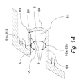
- FIG. 14 shows a vertical cross-section through a fifth embodiment example of the light device according to the present invention.
- FIG. 1 shows a first example of an embodiment of the invention wherein the light device comprises a carrier case 1 covered by a translucent cover 2 , and an inner chamber 3 where a covering mask 4 is mounted, partly limiting the view of the inner chamber 3 , and a light guide 5 designed to emit the output light beam.
- the light guide 5 is mounted in an elastic case 6 whose transversal profile has the shape of U, the elastic case 6 being equipped with two arms 63 oriented opposite each other and fitted with recesses 61 .
- the surface of these recesses 61 represents the contact area 61 a for bearing of the complementary part of the light guide 5 surface to ensure the required mounting position of the light guide 5 , and thus the position of the output surface 51 .
- the outer casing 55 of the light guide 5 in the place of the recess 61 corresponds to the shape of the recess 61 surface with its shape.
- the elastic case 6 and the covering mask 4 are fitted with cooperating fixing elements 7 a , 7 b , e.g. clips and grooves, for firm and dismountable connecting of the case 6 to the covering mask 4 .
- the entire case 6 is made of an elastic material and makes it possible to increase the distance between the arms 63 before the introduction of the light guide 5 into its mounting position, and to reduce the distance again between the arms 63 after the introduction of the light guide 5 into its mounting position.
- the case 6 is connected to the covering mask 4 .
- FIG. 2 shows an example of a light guide for use in the light device in accordance with the invention.
- the linear light guide 5 has a lateral frontal surface 53 on which a light source 8 is arranged to emit light rays 100 into the light guide 5 .
- the light guide 5 made of a plastic transparent material, is fitted with unbinding optical elements 54 in its rear part, e.g. in the form of non-transparent coating or foil attached to the outer casing 55 of the light guide 5 by pressing or injection molding, to direct light rays towards the output surface 51 .
- the light guide 5 is divided into an active part 57 that is designed for the output of light rays 100 out of the light device and into outwardly situated inactive parts 56 .
- the inactive parts 56 are not visible in a view of the inner chamber 3 , e.g. they are concealed with a covering mask 4 .
- locating elements 10 a are situated that are integral parts of the light guide 5 , and are designed to ensure a fixed connection of the light guide 5 to other components of the light device, e.g. the case 6 .
- FIG. 3 shows a second embodiment example of the invention.
- the elastic case 6 of the light guide 5 is firmly connected to the covering mask 4 by means of fixing elements 7 a and 7 b , when a non-dismountable connection is achieved though welding or riveting of the fixing elements 7 a and 7 b .
- the elastic case 6 is fitted with recesses 61 having a shape corresponding to a certain part of the mushroom-like shape of the light guide 5 with the diameter d.
- an active optical element 9 is arranged for reflection of light rays 100 , the active optical element 9 being situated, in a view of the light device, especially behind the unbinding optical elements 54 .
- FIG. 4 shows an elastic case 6 that consists of a transversally oriented rear face 64 from which compression arms 63 lead in the horizontal direction at both the sides.
- the arms 63 are fitted with recesses 61 that form contact areas 61 a for bearing of parts of the light guide 5 surface having the complementary shape.
- fixing arms 62 protrude that form the free ends of the elastic case 6 , their shape and direction corresponding to the covering mask 4 in the place of their mutual contact.
- the arms 63 have surfaces that are situated in parallel, comprising recesses 61 in the form of longitudinally oriented grooves.
- the elastic case 6 is made of an elastic material so that the distance of the arms 63 forming the inner height 65 can be increased at least to the dimension of the diameter “d” of the light guide 5 , the diameter “d” of the light guide 5 corresponding to the mounting height 66 , i.e. the distance between the lowest and highest point of the opposite recesses 61 . (See FIG. 5 .)
- the elastic case 6 is fitted with fixing elements 7 b that are provided on the fixing arms 62 to connect the elastic case 6 and the covering mask 4 .
- the elastic case 6 is fitted with a locating element 10 b on the rear face 64 to fix or stabilize the position of the light guide 5 .
- FIG. 5 and FIG. 6 show a method of attachment of the light guide 5 in a pre-defined and required position.
- the arms 63 can be extended in such a way that the light guide 5 with the diameter “d” can pass through the inner height 65 of the light guide 5 and then bear with a part of its surface on the contact areas 61 a of the elastic case 6 having the corresponding shape.
- the light guide 5 is inserted with its locating element 10 a , situated in the inactive part 56 of the light guide 5 , into the locating element 10 b of the elastic case 6 .
- the arms 63 exert slight thrust upon the light guide 5 .
- the covering mask 4 and the elastic case 6 will get connected to each other by means of the cooperating fixing elements 7 a and 7 b , which will make changing of the distance of the arms 63 , and thus changing of the inner height 65 or the mounting height 66 , impossible.
- the covering mask 4 makes sure that the active part 57 of the light guide 5 is only visible and most of the components of the light device are also hidden.
- FIG. 7 envisages an embodiment wherein the contact area 61 a of the case 6 on each of the arms 63 consists of points lying on two lines (line segments) (see e.g. line 61 b in the embodiment of FIG. 12 ), so the light guide 5 is in contact with the case 6 on each of the arms 63 at the points of its surface lying on the lines 52 .
- FIG. 8 shows a light guide 5 of an elongated shape, on the frontal surface 53 of which a light source 8 is arranged, and whose casing 55 in a certain part, especially in the area of the unbinding optical elements 54 , transmits light rays 100 , forming an emitting surface for the output of light rays 100 that fall upon an active optical element 9 , implemented in the form of a diffusion surface 9 a .
- the active optical element 9 is part of the elastic case 6 and is adapted to reflect light rays 100 .
- the active optical element 9 can be implemented e.g. as reflective foil or as metal plating or as a reflector.
- a part of the light rays 100 flowing through the light guide 5 is reflected from the unbinding optical elements 54 towards the output surface 51 of the light guide 5 .
- a part of the light rays 100 passes through the casing 55 out of the light guide 5 and is reflected from the active optical element 9 , then passes through the casing 55 again, reentering the light guide 5 .
- FIG. 9 shows a light guide 5 transmitting light rays 100 through the casing 55 , the light rays falling upon the optical element 9 implemented in the form of reflective surface 9 b .
- the active optical element 9 is part of the elastic case 6 and is adapted for diffusion of light rays 100 , the light rays 100 being radiated to different directions, being subsequently re-bound to the light guide 5 .
- the elastic case 6 is only situated in the active part 57 of the light guide 5 .
- FIG. 9 envisages an embodiment wherein the contact area 61 a of the case 6 is formed on each of the arms 63 of points lying on a line (line segment) (see e.g., line 61 b in the embodiment of FIG. 14 ), so the light guide 5 is in contact with the case 6 on each of the arms 63 with the points of its surface lying on the line 52 .
- FIG. 10 schematically shows a light guide 5 , the body 58 of which contains unbinding optical elements 54 in the form of diffusion particles 54 b for diffusion and guiding of light rays 100 through the outer casing 55 out of the light guide 5 .
- the light rays 100 exit not only through the output surfaces 51 , but also through the other parts of the outer casing 55 while they fall upon the active optical element 9 situated in a part of the surface of the casing 6 .
- the active optical element 9 is implemented in the form of a diffusion surface 9 a and/or reflective surface 9 b for reflection and/or diffusion of light rays 100 and their binding back to the light guide 5 .
- the light guide 5 is made as one piece with the use of the process of plastic injection molding, the active diffusion particles 54 b being an additive already contained in the plastic before the injection process.
- FIG. 11 is a schematic representation of a light guide 5 whose unbinding optical elements 54 are designed as an array of reflective surfaces 54 a used to reflect light rays towards outer casing 55 or to the body 58 of the light guide 5 .
- FIG. 12 shows a third embodiment example of the light guide wherein the case 6 is fitted with a separate elastic element, which is, in the example shown, molded addition 67 of an elastic material, but a joint or a spring could be used instead.
- the elastic element 69 enables deflection of at least one arm 63 , the arms 63 being fitted with recesses 61 on their inner surface, making it possible to fix the position of the light guide 5 in its mounting position wherein the light guide 5 is in contact with the arms 63 along four lines 61 b altogether.
- the case 6 does not need to be, except the molded addition 67 , made of an elastic material.
- FIG. 13 shows a fourth embodiment example of the light device wherein the case 6 contains a recess 68 , making it possible to extend the arms 63 during the insertion of the light guide 5 into its mounting position, or during withdrawal of the light guide 5 from the mounting position.
- the recess can also be designed as a film hinge.
- the case 6 does not necessarily need to be, except the area of the recess 68 , made of an elastic material.
- FIG. 14 shows a fifth embodiment example of the light device according to the invention wherein the case 6 is, on the transition of the rear face 64 and arm 63 , fitted with a recess 68 having the shape of a notch, making it possible to extend the arms 63 during the insertion of the light guide 5 into its mounting position, or during withdrawal of the light guide 5 from its mounting position.
- the recess 68 can be designed as a film hinge again.
- an active optical element 9 is, forming a chamber 11 together with the light guide 5 in the transversal direction, adapted to reflect/diffuse light rays 100 .
- the contact area 61 a consists of points lying on the line 61 b , and at these points the surface of the light guide 5 touches the arms 63 .
- the light guide 5 has an elliptic shape, the surface of the outer casing 55 being, in all the active area 57 , smooth without protrusions, clicks, recesses and other means that have a negative impact on the guiding of light in the light guide 5 body 58 .
Landscapes
- Engineering & Computer Science (AREA)
- General Engineering & Computer Science (AREA)
- Physics & Mathematics (AREA)
- Optics & Photonics (AREA)
- General Physics & Mathematics (AREA)
- Microelectronics & Electronic Packaging (AREA)
- Planar Illumination Modules (AREA)
Applications Claiming Priority (3)
| Application Number | Priority Date | Filing Date | Title |
|---|---|---|---|
| CZ2016-333A CZ2016333A3 (cs) | 2016-06-03 | 2016-06-03 | Světelné zařízení pro motorová vozidla |
| CZPV2016-333 | 2016-06-03 | ||
| CZ2016-333 | 2016-06-03 |
Publications (2)
| Publication Number | Publication Date |
|---|---|
| US20170350571A1 US20170350571A1 (en) | 2017-12-07 |
| US10126481B2 true US10126481B2 (en) | 2018-11-13 |
Family
ID=60328003
Family Applications (1)
| Application Number | Title | Priority Date | Filing Date |
|---|---|---|---|
| US15/611,572 Active US10126481B2 (en) | 2016-06-03 | 2017-06-01 | Light device for motor vehicles |
Country Status (3)
| Country | Link |
|---|---|
| US (1) | US10126481B2 (de) |
| CZ (1) | CZ2016333A3 (de) |
| DE (1) | DE102017111805B4 (de) |
Families Citing this family (6)
| Publication number | Priority date | Publication date | Assignee | Title |
|---|---|---|---|---|
| US10838137B2 (en) * | 2017-08-29 | 2020-11-17 | Varroc Lighting Systems, s.r.o. | Lighting device with high efficiency and uniformity |
| FR3078140B1 (fr) | 2018-02-19 | 2020-09-11 | Automotive Lighting Rear Lamps France | Dispositif de signalisation de securite attractive pour un vehicule automobile |
| CN112997036B (zh) | 2018-11-02 | 2023-12-01 | 株式会社小糸制作所 | 车辆用灯具 |
| DE102019105250A1 (de) * | 2019-03-01 | 2020-09-03 | HELLA GmbH & Co. KGaA | Leuchtbaugruppe und Verfahren zum Zusammenbauen derselben |
| KR20220045865A (ko) * | 2020-10-06 | 2022-04-13 | 현대자동차주식회사 | 자동차 그릴 |
| DE102021117619A1 (de) * | 2021-07-08 | 2023-01-12 | Bayerische Motoren Werke Aktiengesellschaft | Beleuchtungsvorrichtung für den Außenraum eines Kraftfahrzeugs |
Citations (6)
| Publication number | Priority date | Publication date | Assignee | Title |
|---|---|---|---|---|
| US6402353B2 (en) | 1996-12-17 | 2002-06-11 | Transmatic, Inc. | Lighting system for mass-transit vehicles |
| DE10332977A1 (de) | 2003-07-21 | 2005-07-07 | Hella Kgaa Hueck & Co. | Fahrzeugleuchte |
| EP1775511A1 (de) | 2005-10-11 | 2007-04-18 | Valeo Vision | Kfz-Signal- und/oder Beleuchtungseinrichtung mit einem Lichtleiter |
| CZ2010955A3 (cs) | 2010-12-21 | 2012-07-04 | ŠKODA AUTO a.s. | Zarízení k upevnení svetlometu |
| EP1540389B1 (de) | 2002-09-17 | 2013-12-25 | Tyco Electronics Canada ULC | Beleuchtungsvorrichtung mit lichtleiter und leuchtenanordnung |
| US9182095B2 (en) | 2012-10-04 | 2015-11-10 | Valeo Iluminacion Sociedad Anonima | Lighting and/or signaling module for a vehicle comprising a light guide with a rib and a support with means of attachment collaborating with the rib |
Family Cites Families (3)
| Publication number | Priority date | Publication date | Assignee | Title |
|---|---|---|---|---|
| DE102007010023B4 (de) | 2006-03-03 | 2011-07-21 | Truck-Lite Europe GmbH, 99817 | Fahrzeugleuchte |
| GB0813186D0 (en) | 2008-07-18 | 2008-08-27 | 3M Innovative Properties Co | Lighting device comprising a light guide and a support |
| AT514405B1 (de) | 2013-06-07 | 2015-05-15 | Zkw Slovakia S R O | Beleuchtungskörper für ein Fahrzeug |
-
2016
- 2016-06-03 CZ CZ2016-333A patent/CZ2016333A3/cs unknown
-
2017
- 2017-05-30 DE DE102017111805.5A patent/DE102017111805B4/de active Active
- 2017-06-01 US US15/611,572 patent/US10126481B2/en active Active
Patent Citations (7)
| Publication number | Priority date | Publication date | Assignee | Title |
|---|---|---|---|---|
| US6402353B2 (en) | 1996-12-17 | 2002-06-11 | Transmatic, Inc. | Lighting system for mass-transit vehicles |
| EP1540389B1 (de) | 2002-09-17 | 2013-12-25 | Tyco Electronics Canada ULC | Beleuchtungsvorrichtung mit lichtleiter und leuchtenanordnung |
| DE10332977A1 (de) | 2003-07-21 | 2005-07-07 | Hella Kgaa Hueck & Co. | Fahrzeugleuchte |
| EP1775511A1 (de) | 2005-10-11 | 2007-04-18 | Valeo Vision | Kfz-Signal- und/oder Beleuchtungseinrichtung mit einem Lichtleiter |
| US7726854B2 (en) | 2005-10-11 | 2010-06-01 | Valeo Vision | Lighting or signal device with an optical guide for a motor vehicle |
| CZ2010955A3 (cs) | 2010-12-21 | 2012-07-04 | ŠKODA AUTO a.s. | Zarízení k upevnení svetlometu |
| US9182095B2 (en) | 2012-10-04 | 2015-11-10 | Valeo Iluminacion Sociedad Anonima | Lighting and/or signaling module for a vehicle comprising a light guide with a rib and a support with means of attachment collaborating with the rib |
Non-Patent Citations (1)
| Title |
|---|
| Search Report in Corresponding Czech Application PV 2016-333 dated Oct. 6, 2016 (3 pages). |
Also Published As
| Publication number | Publication date |
|---|---|
| DE102017111805A1 (de) | 2017-12-07 |
| CZ2016333A3 (cs) | 2017-12-13 |
| DE102017111805B4 (de) | 2021-12-02 |
| US20170350571A1 (en) | 2017-12-07 |
Similar Documents
| Publication | Publication Date | Title |
|---|---|---|
| US10126481B2 (en) | Light device for motor vehicles | |
| CN104459869B (zh) | 机动车的照明装置 | |
| EP2990720B1 (de) | Fahrzeugbeleuchtungsvorrichtung | |
| US5816681A (en) | Inconspicuous light sources particularly for vehicular applications | |
| CN106195849B (zh) | 照明装置和包括该装置的照明和/或信号指示模块 | |
| US20140078764A1 (en) | Vehicular Lamp | |
| US20140211493A1 (en) | Vehicle lighting unit | |
| JP2007180027A (ja) | 自動車用光ガイド搭載照明または信号装置 | |
| EP2840300B1 (de) | Kraftfahrzeuglicht | |
| JP6571408B2 (ja) | 車輌用灯具 | |
| CN103885115B (zh) | 导光体及照明装置 | |
| CN107850284B (zh) | 车用灯具 | |
| JP2016178024A (ja) | 車両用灯具 | |
| KR20160123286A (ko) | 차량용 광 가이드를 구비한 조명 및/또는 신호 시스템 | |
| JP2016527685A (ja) | 照明方向の面内にプリント回路基板を備える、特に自動車の照明部材のための照明システム | |
| JP2019160749A (ja) | 車両用灯具 | |
| JP2020503647A (ja) | 自動車ヘッドライト用の導光板を有する発光モジュール | |
| EP2884156A1 (de) | Lichtleitervorrichtung und dazugehörige Leuchte | |
| JP2012064534A (ja) | 車両用灯具 | |
| CN110762479B (zh) | 车辆用灯具 | |
| US20150078023A1 (en) | Lighting Device for Vehicles | |
| JP7100530B2 (ja) | 車輌用灯具 | |
| CN108626679B (zh) | 一种基于光导的用于机动车辆的光源组件 | |
| JP2014164975A (ja) | 車両用灯具 | |
| CN215216048U (zh) | 一种导光装置、车灯及车辆 |
Legal Events
| Date | Code | Title | Description |
|---|---|---|---|
| AS | Assignment |
Owner name: VARROC LIGHTING SYSTEMS, S.R.O., CZECH REPUBLIC Free format text: ASSIGNMENT OF ASSIGNORS INTEREST;ASSIGNORS:GOLD, PAVEL;MARTOCH, JAN;REEL/FRAME:042756/0713 Effective date: 20170608 |
|
| STCF | Information on status: patent grant |
Free format text: PATENTED CASE |
|
| MAFP | Maintenance fee payment |
Free format text: PAYMENT OF MAINTENANCE FEE, 4TH YEAR, LARGE ENTITY (ORIGINAL EVENT CODE: M1551); ENTITY STATUS OF PATENT OWNER: LARGE ENTITY Year of fee payment: 4 |
|
| AS | Assignment |
Owner name: PO LIGHTING CZECH S.R.O., CZECH REPUBLIC Free format text: MERGER;ASSIGNOR:VARROC LIGHTING SYSTEMS, S.R.O.;REEL/FRAME:064126/0456 Effective date: 20221014 |