US10080507B2 - Systems and methods for detecting physical changes without physical contact - Google Patents
Systems and methods for detecting physical changes without physical contact Download PDFInfo
- Publication number
- US10080507B2 US10080507B2 US15/418,328 US201715418328A US10080507B2 US 10080507 B2 US10080507 B2 US 10080507B2 US 201715418328 A US201715418328 A US 201715418328A US 10080507 B2 US10080507 B2 US 10080507B2
- Authority
- US
- United States
- Prior art keywords
- electric field
- amplitude
- changes
- frequency
- response
- Prior art date
- Legal status (The legal status is an assumption and is not a legal conclusion. Google has not performed a legal analysis and makes no representation as to the accuracy of the status listed.)
- Active, expires
Links
Images


Classifications
-
- A—HUMAN NECESSITIES
- A61—MEDICAL OR VETERINARY SCIENCE; HYGIENE
- A61B—DIAGNOSIS; SURGERY; IDENTIFICATION
- A61B5/00—Measuring for diagnostic purposes; Identification of persons
- A61B5/05—Detecting, measuring or recording for diagnosis by means of electric currents or magnetic fields; Measuring using microwaves or radio waves
-
- A—HUMAN NECESSITIES
- A61—MEDICAL OR VETERINARY SCIENCE; HYGIENE
- A61B—DIAGNOSIS; SURGERY; IDENTIFICATION
- A61B5/00—Measuring for diagnostic purposes; Identification of persons
- A61B5/02—Detecting, measuring or recording pulse, heart rate, blood pressure or blood flow; Combined pulse/heart-rate/blood pressure determination; Evaluating a cardiovascular condition not otherwise provided for, e.g. using combinations of techniques provided for in this group with electrocardiography or electroauscultation; Heart catheters for measuring blood pressure
- A61B5/024—Detecting, measuring or recording pulse rate or heart rate
-
- A—HUMAN NECESSITIES
- A61—MEDICAL OR VETERINARY SCIENCE; HYGIENE
- A61B—DIAGNOSIS; SURGERY; IDENTIFICATION
- A61B5/00—Measuring for diagnostic purposes; Identification of persons
- A61B5/72—Signal processing specially adapted for physiological signals or for diagnostic purposes
- A61B5/7228—Signal modulation applied to the input signal sent to patient or subject; demodulation to recover the physiological signal
-
- A—HUMAN NECESSITIES
- A61—MEDICAL OR VETERINARY SCIENCE; HYGIENE
- A61B—DIAGNOSIS; SURGERY; IDENTIFICATION
- A61B5/00—Measuring for diagnostic purposes; Identification of persons
- A61B5/72—Signal processing specially adapted for physiological signals or for diagnostic purposes
- A61B5/7235—Details of waveform analysis
- A61B5/725—Details of waveform analysis using specific filters therefor, e.g. Kalman or adaptive filters
-
- A—HUMAN NECESSITIES
- A61—MEDICAL OR VETERINARY SCIENCE; HYGIENE
- A61B—DIAGNOSIS; SURGERY; IDENTIFICATION
- A61B5/00—Measuring for diagnostic purposes; Identification of persons
- A61B5/72—Signal processing specially adapted for physiological signals or for diagnostic purposes
- A61B5/7271—Specific aspects of physiological measurement analysis
- A61B5/7278—Artificial waveform generation or derivation, e.g. synthesising signals from measured signals
-
- A—HUMAN NECESSITIES
- A61—MEDICAL OR VETERINARY SCIENCE; HYGIENE
- A61B—DIAGNOSIS; SURGERY; IDENTIFICATION
- A61B5/00—Measuring for diagnostic purposes; Identification of persons
- A61B5/74—Details of notification to user or communication with user or patient ; user input means
- A61B5/742—Details of notification to user or communication with user or patient ; user input means using visual displays
-
- G—PHYSICS
- G01—MEASURING; TESTING
- G01R—MEASURING ELECTRIC VARIABLES; MEASURING MAGNETIC VARIABLES
- G01R29/00—Arrangements for measuring or indicating electric quantities not covered by groups G01R19/00 - G01R27/00
- G01R29/08—Measuring electromagnetic field characteristics
- G01R29/0807—Measuring electromagnetic field characteristics characterised by the application
- G01R29/0814—Field measurements related to measuring influence on or from apparatus, components or humans, e.g. in ESD, EMI, EMC, EMP testing, measuring radiation leakage; detecting presence of micro- or radiowave emitters; dosimetry; testing shielding; measurements related to lightning
-
- A—HUMAN NECESSITIES
- A61—MEDICAL OR VETERINARY SCIENCE; HYGIENE
- A61B—DIAGNOSIS; SURGERY; IDENTIFICATION
- A61B5/00—Measuring for diagnostic purposes; Identification of persons
- A61B5/08—Detecting, measuring or recording devices for evaluating the respiratory organs
- A61B5/0816—Measuring devices for examining respiratory frequency
-
- A—HUMAN NECESSITIES
- A61—MEDICAL OR VETERINARY SCIENCE; HYGIENE
- A61B—DIAGNOSIS; SURGERY; IDENTIFICATION
- A61B5/00—Measuring for diagnostic purposes; Identification of persons
- A61B5/72—Signal processing specially adapted for physiological signals or for diagnostic purposes
- A61B5/7225—Details of analog processing, e.g. isolation amplifier, gain or sensitivity adjustment, filtering, baseline or drift compensation
Definitions
- This application relates generally to the technical field of monitoring systems, and more particularly, to a monitoring system that detects physical changes without physical contact.
- monitoring systems may be affected by where a sensor or its parts are placed relative to a target (e.g., a human such as an adult, teen, child, or baby) that is being monitored.
- a target e.g., a human such as an adult, teen, child, or baby
- certain monitoring systems may require a sensor to be in physical contact with a target and may further require a part (e.g., a power or data cable) to be connected from a sensor to a monitoring device.
- a part e.g., a power or data cable
- the sensor might be used to detect changes in occupancy of a vehicle seat. In this case the sensor might also sense vital signs—e.g., pulse and/or respiration—of a seat occupant without direct physical contact.
- a traditional electrocardiogram uses external electrodes to detect a patient's ECG signal.
- the external electrodes are located on the ends of cables and must be physically placed on a patient and near the patient's heart. This often necessitates the use of conductive materials that may be inconvenient to hook up and use, especially for long-term monitoring of a relatively active patient.
- ECG electrocardiogram
- These devices have significant limitations. For example, the patient must be physically connected to the device. If the patient wants to leave his or her bed, the device needs to be detached from, and then re-attached to the patient on his/her return, often by a highly trained staff member.
- monitoring systems are also not well-suited for monitoring more active targets, for example, a baby in a crib or a person driving a vehicle.
- monitoring systems incorporated into devices such as wristbands and armbands they still typically need to be directly in contact with the target, and often provide inaccurate information and limited functionality.
- a monitoring system that does not require a sensor to be directly in contact with a target.
- a monitoring system that can assist in the management of a target's health, fitness, sleep and diet by monitoring physiological changes in a person's body.
- a monitoring system suitable for long-term use that can sense changes in a target and provide timely and appropriate diagnostic, prognostic and prescriptive information.
- This invention includes systems and methods that allow detection of physical changes within a body without physical contact with, or attachment to, the body.
- a body is a mass of matter distinct from other masses.
- Non-limiting examples of a body include, for example, a human's body, an animal's body, a container, a car, a house, etc. These changes might be physiological events such as cardiac function in an animal or changes in the properties of a bulk material such as grain in a silo. These changes could be dimensional changes such as those caused by the function of organs in an animal, or changes in the composition of the material such as water content in lumber.
- a key feature of the measurement technique used in this instrument is that the measurement may be done over an extended volume such that the changes of multiple phenomena may be observed simultaneously. For example, sensing two separate but related physiological parameters (e.g., pulse and respiration) may be accomplished concurrently. The region sensed by this instrument may be changed by sensor element design within the instrument.
- a further extension of bulk sensing capability is the opportunity to use sophisticated computer signature recognition software, such as wavelet-based approaches, to separate individual features from the composite waveform.
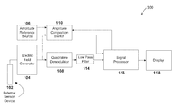
- Disclosed subject matter includes, in one aspect, a system for detecting and analyzing changes in a body.
- the system includes an electric field generator configured to produce an electric field.
- the system includes an external sensor device, coupled to the electric field generator, configured to detect physical changes in the electric field, where the physical changes affect amplitude and frequency of the electric field.
- the system includes a quadrature demodulator, coupled to the electric field generator, configured to detect changes of the frequency of the output of the electric field generator and produce a detected response that includes a low frequency component and a high frequency component.
- the system includes a low pass filter, coupled to the quadrature demodulator, configured to filter out the high frequency component of the detected response to generate a filtered response.
- the system includes an amplitude reference source configured to provide an amplitude reference.
- the system includes an amplitude comparison switch, coupled to the amplitude reference source and the electric field generator, configured to compare the amplitude reference and the amplitude of the electric field to generate an amplitude comparison.
- They system includes a signal processor, coupled to the low pass filter and the amplitude comparison switch, configured to analyze the filtered response and the amplitude comparison response.
- Disclosed subject matter includes, in another aspect, a method for detecting and analyzing changes in a body.
- the method includes establishing an electric field around a desired area of detection with an electric field generator.
- the method includes monitoring frequency of the electrical field with a quadrature demodulator.
- the method includes detecting changes in the frequency of the electric field with the quadrature demodulator.
- the method includes monitoring amplitude of the electric field.
- the method includes detecting changes in the amplitude of the electric field with an amplitude reference source.
- Disclosed subject matter includes, in yet another aspect, a non-transitory computer readable medium having executable instructions operable to cause an apparatus to establish an electric field around a desired area of detection with an electric field generator.
- the instructions are further operable to cause the apparatus to monitor frequency of the electrical field with a quadrature demodulator.
- the instructions are further operable to cause the apparatus to detect changes in the frequency of the electric field with the quadrature demodulator.
- the instructions are further operable to cause the apparatus to monitor amplitude of the electric field.
- the instructions are further operable to cause the apparatus to detect changes in the amplitude of the electric field with an amplitude reference source.
- FIG. 1 illustrates a system for detecting and analyzing changes in a body according to certain embodiments of the present disclosure.
- FIG. 2 illustrates a transfer function of a quadrature demodulator according to certain embodiments of the present disclosure.
- FIG. 3 illustrates a waveform combining both respiration and heart rate signals according to certain embodiments of the present disclosure.
- FIG. 4 illustrates a system for detecting and analyzing changes in a body according to certain embodiments of the present disclosure.
- FIG. 5 illustrates a process of detecting and analyzing changes in a body according to certain embodiments of the present disclosure.
- FIG. 6 illustrates a quadrature demodulator according to certain embodiments of the present disclosure.
- FIG. 7 illustrates a signal processor according to certain embodiments of the present disclosure.
- AC alternating current
- energy storage occurs in both electric and magnetic fields created by the current.
- Dissipation occurs in transformation, in the material, of electrical energy into thermal energy, i.e., heat.
- Dissipation in some materials may be attributed to the magnetic field properties of a material and in other cases to the electric field properties. In more general cases, both of these mechanisms are present. Because of this, there is a convention in which the magnetic field storage properties and any related dissipation are combined in a vector sum and called permeability. Similarly, the vector sum of the electric field storage properties and associated dissipation is called permittivity. These vector sums are expressed as complex values in which the dissipation is the real component and field storage properties are the imaginary component. In the present disclosure, the aggregated change in properties of a body are detected and quantified by measuring changes in the body's electromagnetic properties.
- the instrument in this invention detects changes in permittivity. Detection of any other suitable property or combination of properties that are appreciated by a person skilled in the art is also within the spirit and limit of the disclosed subject matter.
- the dissipative component of permittivity often is expressed as the loss tangent of the material, while the storage term is called capacitance. Measuring these properties is accomplished by sensing the change of phase and amplitude of an electric field generated by the instrument and caused by the aggregated properties of a body within the field.
- FIG. 1 illustrates a system 100 for detecting and analyzing changes in a body according to certain embodiments of the present disclosure.
- the system 100 includes an external sensor device 102 , an electric field generator 104 , an amplitude reference source 106 , a quadrature modulator 108 , an amplitude comparison switch 110 , a low pass filter 114 , a signal processor 116 , and a display 118 .
- the components included in the system 100 can be further broken down into more than one component and/or combined together in any suitable arrangement. Further, one or more components can be rearranged, changed, added, and/or removed. In some embodiments, one or more components of the system 100 can be made by an application specific integrated circuit (ASIC).
- ASIC application specific integrated circuit
- the electric field generator 104 creates an electric field that illuminates the desired area of detection. The frequency and amplitude of this electric field is determined by the characteristics of the body being observed.
- a frequency-determining component of the electric field generator 104 a resonant circuit than can comprised of a combination of inductive, capacitive, and resistive elements—is connected to an external device that creates the electric field providing the desired coverage of the body of material being studied.
- the electric field generator 104 can be an oscillator, such as an inductor-capacitor (LC) tank oscillator.
- the external sensor device 102 may be made from a wide variety of materials; the only requirement of these materials is that they are electrical conductors.
- the external sensor device 102 can be constructed in many different mechanical configurations to provide appropriate coverage of the desired region.
- the external sensor device 102 can be a plurality of metallic plates.
- the shape and/or the orientation of the external sensor device 102 can be changed as needed.
- the external sensor device 102 is not required to physically contact the body being studied.
- the external sensor device 102 and the supporting electronics could be installed in the driver's seat of an over-the-highway truck to detect changes in physiological indicators of driver drowsiness and thus take actions to prevent an accident.
- the sensing process usually is done separately in two paths: (1) in a first path the changes in the real component of the vector sum, e.g., energy dissipation, are detected; (2) in a second path the changes related to the imaginary component—a component such as a capacitance or inductance in which the phase of the current flowing in them is orthogonal to the current in the real component—are separately processed.
- the changes in amplitude of the electric field are detected in the first path, and the changes in frequency of the electric field are detected in the second path.
- the changes in phase of the electric field can be obtained by analyzing the changes in frequency of the electric field.
- FIG. 6 illustrates a quadrature demodulator 108 according to certain embodiments of the present disclosure.
- the quadrature demodulator 108 includes a mixer 602 and a resonant circuit 604 .
- a double balanced mixer is described, but other suitable types of mixers can also be used.
- the components included in the quadrature demodulator 108 can be further broken down into more than one component and/or combined together in any suitable arrangement. Further, one or more components can be rearranged, changed, added, and/or removed.
- An input signal to the quadrature demodulator 108 is split into two paths. One path is connected to one input port of the double balanced mixer 602 , and the other path is connected to the resonant circuit 604 .
- the output of the resonant circuit 604 is connected to the other input port of the double balanced mixer 602 .
- the resonant circuit 604 includes an inductor and a capacitor.
- the resonant circuit 604 includes an inductor, a capacitor, and a resistor.
- the circuit components of the resonant circuit 604 can be connected in series, in parallel, or any other suitable configuration.
- the resonant circuit 604 can also be implemented by other circuit configurations that are appreciated by a person skilled in the art.
- the resonant circuit 604 is tuned to the nominal center frequency of the electric field generator 104 .
- the double balanced mixer 602 multiplies the two signals together (one signal from the input and the other signal from the resonant circuit 604 ).
- the product of the two signals creates two components in the output: one proportional to the difference between the two input frequencies and another at the sum of the two input frequencies.
- the demodulator output is zero.
- the phase difference is less than about +/ ⁇ 90 degrees there will be a DC component in the output of the double balanced mixer 602 .
- the output signal from the quadrature demodulator 108 is fed to a low pass filter 114 .
- the low pass filter 114 is typically an analog circuit that includes resistive, inductive and/or capacitive elements that separates the low frequency component of the quadrature modulator 108 from the much higher frequency component generated by the quadrature modulator 108 .
- the cutoff frequency of the low pass filter is selected to provide low attenuation of the desired signal components while sufficiently suppressing the high frequency terms.
- the signal is connected to the signal processor unit 116 described below.
- Detecting changes in electric field dissipation is processed somewhat different from detecting frequency changes in electric field.
- the output of the electric field generator 104 is multiplied by a phase-shifted version of itself produced by the resonant circuit 604 .
- amplitude variations must be compared with the electric field generator 104 output unchanged by the material being studied.
- an amplitude reference signal is created by measuring the output of the electric field generator 104 in the absence of any external influence and used to set the output level of the amplitude reference source 106 .
- the amplitude reference source 106 is typically a time and temperature stable voltage reference that can be provided by a semiconductor component such as a diode.
- the output of the amplitude reference source 106 is fed to one input of the amplitude comparison switch 110 .
- the switch 110 controlled by the signal processor 116 , alternately connects the amplitude reference source 106 and electric field generator output 104 to the signal processor 116 .
- the amount of power absorbed, e.g., dissipated, by the material under study may be computed.
- the amplitude comparison switch 110 functions by sampling the output of the electric field generator 104 at a rate at least twice as fast as the most rapid variation of the amplitude of the electric field generator 104 and subtracting the value of the amplitude reference source 106 .
- the output of the amplitude comparison switch 110 is thus equal to the difference between the amplitude of the electric field generator 104 and the amplitude of the amplitude reference source 106 .
- the signal processor 116 takes the output of the low pass filter 114 and extracts the desired components into desired formats for further use or processing.
- the signal processor 116 also takes the output of the amplitude comparison switch 110 to analyze the changes in amplitude of the electric field.
- the signal processor 116 can be implemented by use of either analog, digital, or combined circuits.
- FIG. 7 illustrates a signal processor 116 according to certain embodiments of the present disclosure.
- the signal processor 116 includes a sample-and-hold circuit 702 , an analog-to-digital converter (ADC) 704 , a digital signal processor 706 , and a microcontroller 708 .
- ADC analog-to-digital converter
- the components included in the signal processor 116 can be further broken down into more than one component and/or combined together in any suitable arrangement. Further, one or more components can be rearranged, changed, added, and/or removed.
- the sample-and-hold circuit 702 is configured to sample a continuous-time continuous-value signal and hold the value for a specified period of time.
- a typical sample-and-hold circuit 702 includes a capacitor, one or more switches, and one or more operational amplifier. In some embodiments, other suitable circuit implementations can also be used.
- the ADC 704 receives the output of the sample-and-hold circuit 702 and converts it into digital signals.
- the ADC 410 can have a high resolution. Since the changes in bulk permittivity of the entire region within the electric field in many possible applications are expected to be relatively slow, e.g., less than a few hundred Hertz, in some embodiments it can be sufficient to undersample the output of the electric field generator 404 by using the sample-and-hold device 406 to make short samples that can be processed with the ADC 704 with a sample rate in the five thousand samples/sec range. An ADC with 24-bit resolution or 32-bit resolution are readily available. In some embodiments, the ADC 704 can have other suitable resolutions.
- the digital signal processor 706 can be configured process the output of the ADC 704 .
- the digital signal processor 706 can be a microprocessor.
- the microcontroller 708 can be coupled to one or more components of the signal processor 116 .
- the microcontroller 708 can control the sampling rate and/or clock rate of the one or more components of the signal processor 116 .
- the microcontroller 708 can issue command signals to the one or more components of the signal processor 116 .
- the microcontroller 708 can be a generic high performance low power system on chip (SOC) product.
- the microcontroller 708 can be an ARM based processor, such as an ARM Cortex-M4 core processor or any other suitable models.
- the display 118 can be configured to display various results generated by the signal processor 116 .
- the display 118 can be a touch screen, an LCD screen, and/or any other suitable display screen or combination of display screens.
- the output of the signal processor 116 can also be fed to a data logger for signal storage and/or processing.
- FIG. 2 shows a generalized version of the transfer function of a quadrature demodulator 108 showing the typical relationship between the voltage output and frequency of the input signal from the electric field generator 104 .
- the horizontal axis shows frequency of the input signal in Hertz (Hz), and the vertical axis shows demodulator output in Volt (V).
- the center of the horizontal axis 210 indicates the nominal resonant frequency of the resonant circuit 604 . For example, if the nominal resonant frequency of the resonant circuit 604 is 80 MHz, then the center of the horizontal axis 210 is at 80 MHz.
- the slope of the central region 202 of the curve can be made quite linear to allow operation over an extended frequency range while offering the same sensitivity in terms of output voltage as function of phase/frequency change.
- the transfer function is mathematically dependent only on the frequency/phase relationship between the two inputs to the double-balanced mixer 108 . This permits a wide and dynamic range in detection in the phase/frequency changes induced by material properties separate from changes in amplitude due to dissipative properties.
- FIG. 2 illustrates the sensor operating as it might be employed in two different applications while using the same electric field generator 104 and the quadrature demodulator 108 .
- the DC component dependent on the exact value of the frequency and slope of the transfer function—might be, for example, ⁇ 1.5 volts. If there are small variations in the frequency of the electric field generator 104 , there will also be small variations in the quadrature demodulator output voltage. For the example here the output variations will be centered about ⁇ 1.5 volts.
- the DC term might be, for example, around +1.0 volts. However, since the slope of the transfer function is very close to being the same in both regions, the small variations will be centered around 0 volts.
- the aggregated output of the quadrature demodulator 108 can have a mean DC level determined by the contributions of all materials within the electric field region, while still maintaining an essentially constant transfer function for small changes in material properties.
- the small-signal linearity allows signal components from separate constituents of the material being studied to be linearly combined. Linear combination of the various contributions in the output waveform can be readily separated in later signal processing.
- An example of a combined waveform showing both respiration and heart rate (pulse) signals is shown in FIG. 3 .
- FIG. 3 shows a signal comprised of a large, low frequency, roughly triangular waveform that might be typical of respiration by a body and a signal often seen in a heart pulse of smaller amplitude, higher frequency, and more complex waveform.
- the linear addition of these two waveforms is shown as the smaller amplitude, higher frequency, more complex heart pulse “riding” on the larger, slower triangular respiration component.
- FIG. 4 illustrates a system 400 for detecting and analyzing changes in a body according to certain embodiments of the present disclosure.
- the system 400 includes an external sensor device 402 , an electric field generator 404 , a sample-and-hold device 406 , a microcontroller 408 , an ADC 410 , a digital signal processor 416 , and a display 418 .
- the components included in the system 400 can be further broken down into more than one component and/or combined together in any suitable arrangement. Further, one or more components can be rearranged, changed, added, and/or removed. In some embodiments, the components included in FIG. 4 are similar to the corresponding components described in FIG. 1 and/or FIG. 7 .
- the system 400 replaces most analog components described in FIG. 1 with digital or mixed-signal components.
- the “direct-to-digital” concept employs the ADC 410 driven by the sample-and-hold device 406 .
- the ADC 410 can have a high resolution. Since the changes in bulk permittivity of the entire region within the electric field in many possible applications are expected to be relatively slow, e.g., less than a few hundred Hertz, it can be sufficient to undersample the output of the electric field generator 404 by using the sample-and-hold device 406 to make short samples that can be processed with the ADC 410 with a sample rate in the five thousand samples/sec range.
- the signal processor 416 would take over the functions performed by the quadrature demodulator 108 described in FIG. 1 . Since the features of the “direct-to-digital” instrument would be determined by the software in the signal processor 416 , a single hardware set could be loaded with specialized software for different applications. The programmable characteristics of a “direct-to-digital” approach could enable economies of scale, driving down the unit cost and opening new market opportunities.
- the ADC can be made by an application specific integrated circuit (ASIC).
- FIG. 5 is a flow chart illustrating a process 500 of detecting and analyzing changes in a body according to certain embodiments of the present disclosure.
- the process 500 is illustrated in connection with the system 100 shown in FIG. 1 and/or the system 400 shown in FIG. 4 .
- the process 500 can be modified by, for example, having steps rearranged, changed, added, and/or removed.
- an electric field is established around the desired area of detection.
- the desired area of detection is typically around a body that is going to be monitored.
- the electrical field is established by using the electric field generator 104 , which creates an electric field that illuminates the desired area of detection.
- the process 500 then proceeds to step 504 .
- the frequency and amplitude of the electric field of the desired area of detection are monitored.
- the external sensor device 102 is used to monitor the area around and within the body. The external sensor device 102 is not required to physically contact the body being studied. The process 500 then proceeds to step 506 .
- the electric field of the desired area of detection is processed and analyzed to detect any change.
- the process 500 can detect the change of the electric field in both amplitude and frequency/phase. For example, amplitude variations of the electric field can be compared with the electric field generator 104 output unchanged by the material being studied.
- an amplitude reference signal is created by measuring the output of the electric field generator in the absence of any external influence and used to set the output level of the amplitude reference source 106 .
- the output of the amplitude reference source 106 is fed to one input of the amplitude comparison switch 110 .
- the switch 110 controlled by the signal processor 116 , alternately connects the amplitude reference source 106 and electric field generator output 106 to the signal processor.
- the change of the electric field in frequency/phase can be detected and analyzed by the quadrature demodulator configuration discussed in connection with FIG. 1 and FIG. 6 .
- the output of the electric field generator 104 is connected to the quadrature demodulator that is configured to detect the changes of the frequency of the output of the electric field generator 104 and produce a detected response that includes a low frequency component and a high frequency component.
- the detected response is then fed to a low pass filter 114 that is configured to filter out the high frequency component of the detected response to generate a filtered response.
- the changes in phase can be readily derived by people skilled in the art.
- the filtered response and the amplitude comparison response can then be supplied to a signal processor for further analysis.
- the change of the electric field can be analyzed under the “direct-to-digital” approach described in the system 400 in connection with FIG. 4 .
- the output of the electric field generator 404 can be sampled and held by the sample-and-hold device 406 and digitized by the ADC 410 .
- the digitized output of the ADC 410 can then be analyzed by the digital signal processor 416 .
- the process 500 then proceeds to step 508 .
- the electric field can be displayed for visual inspection.
- the changes of the electric field can also be displayed and recorded.
- the changes of the electric field can be extracted to provide specific bodily function features such as vascular processes and conditions, respiration processes and conditions, and other body material characteristics that vary with permittivity.
- the system 100 or the system 400 can include a processor, which can include one or more cores and can accommodate one or more threads to run various applications and modules.
- the software can run on the processor capable of executing computer instructions or computer code.
- the processor may also be implemented in hardware using an application specific integrated circuit (ASIC), programmable logic array (PLA), field programmable gate array (FPGA), or any other integrated circuit.
- ASIC application specific integrated circuit
- PLA programmable logic array
- FPGA field programmable gate array
- the processor can be couple with a memory device, which can be a non-transitory computer readable medium, flash memory, a magnetic disk drive, an optical drive, a PROM, a ROM, or any other memory or combination of memories.
- a memory device can be a non-transitory computer readable medium, flash memory, a magnetic disk drive, an optical drive, a PROM, a ROM, or any other memory or combination of memories.
- the processor can be configured to run a module stored in the memory that is configured to cause the processor to perform various steps that are discussed in the disclosed subject matter.
- changes in capacitor excitation frequency can be remotely sensed to alleviate the need for analog data reduction at the sensor.
- blood pressure can be measured by isolating a body region using a pressure “doughnut” and then releasing pressure and monitoring the return of blood flow as a result.
- Traditional means enclosing a limb to close an artery and monitor the pressure at which the artery opens up as the pressure is released.
- a body region can be determined that excludes blood by closing capillaries (within the ‘doughnut’ pressure region) and monitoring the pressure at which they then open again. This simplification of application could then be applied to in-seat circumstances in hospital/clinic waiting rooms and the like.
- first derivatives can be used to find a recurring pattern in a combined time series signal of heartbeat and respiration such that the respiration signal can be subtracted from the combined signal to leave the heartbeat signal.
- the mathematical notion of Entropy (H) can be used to analyze a heartbeat signal and extract event timing information with respect to characterizing heart processes.
- wavelet analysis can be used to disambiguate complex time series data with highly variable frequency compositions. Signals that vary their frequency in time are resistant to effective analysis using traditional digital techniques such as fast Fourier transform (FFT). Wavelets provide the notion of short pattern correlation that can be applied to a sliding window of time series data in order to provide a second correlation time series that indicates the time at which a test pattern or “wavelet” is found within the first time series.
- FFT fast Fourier transform
- a low resolution FFT can be used to peak search for power levels in a correlation function. This FFT power analysis is then used to set the correlation cutoff level and thus determine higher resolution correlated frequencies based on the power levels provides by the FFT.
- the FFT essentially filters out correlations below a particular power level so that more strongly correlated signals can remain. This provides a way of efficiently ‘normalizing’ the power levels relative to one another in trying to separate low frequency signals that are relatively close in frequency but widely separated in power without having to increase the resolution of the FFT with attendant significantly increased FFT window acquisition time.
- Kalman filters can be used to process the effect of changes in permittivity as indicated by a time series data such that the filter relates the predicted next value in a time series in maintaining a useable moving average for the purposes of normalizing a highly variable signal from a sensor with high dynamic range.
- measurement of the temperature of a body or substance can be obtained by measuring the permittivity of said body or substance where such permittivity may be correlated to temperature.
- measurement of the pressure within a body, substance, and/or liquid can be obtained by measuring the permittivity of said body, substance, and/or liquid where such permittivity may be correlated to pressure.
- stress levels in an individual can be determined by analyzing his or her motion, heartbeat characteristics and respiration using a remote, non-contact, biometric sensor.
- the quality of food in food processing and handling operations can be monitored by correlating the qualities of the food to the measured permittivity of the food item.
- the characteristics e.g., turbulence, flow, density, temperature
- a fluid e.g., paint, blood, reagents, petroleum products
- correlating the characteristics of the fluid can be monitored by correlating the characteristics of the fluid to the objective characteristics of the fluid.
- cavities and/or impurities in solid materials can be found. Such application can be used in areas such as the detection of delamination in composite materials, voids in construction materials, entrained contaminants, and/or the quality of fluid mixing.
- contraband enclosed within solid objects can be found.
- the life signs of infants in cribs, pushchairs and/or car seats can be monitored.
- the presence and life signs located in automobiles can be detected for the purposes of providing increased passenger safety, deploying airbags, and/or prevent baby from being left behind.
- the sentience of a driver can be detected by using heartbeat variability.
- gestures such as the head-nod signature motion.
- the life signs in unauthorized locations can be discovered.
- the quality of glass manufacture can be assessed by detecting variations in thickness, poor mixing, and/or the entrainment of impurities and/or.
- the nature of underground/sub-surface texture and infrastructure can be assessed.
- the external sensor device disclosed herein can be combined with other sensors (e.g., camera, echolocation, pressure/weight/accelerometers) to provide enhanced sensor application using sensor “fusion.”
- sensors e.g., camera, echolocation, pressure/weight/accelerometers
- certain body conditions can be detected.
- the body conditions include conditions of the body relating to heart-lung functions, pulmonary fluid levels, blood flow and function, large and small intestine condition and process, bladder condition (full/empty) and process (rate fill/empty), edema and related fluid conditions, bone density measurement, and any other suitable condition or combination of conditions.
Priority Applications (10)
| Application Number | Priority Date | Filing Date | Title |
|---|---|---|---|
| US15/418,328 US10080507B2 (en) | 2016-01-27 | 2017-01-27 | Systems and methods for detecting physical changes without physical contact |
| US16/058,821 US11026593B2 (en) | 2016-01-27 | 2018-08-08 | Systems and methods for detecting physical changes without physical contact |
| US16/139,993 US10631752B2 (en) | 2016-01-27 | 2018-09-24 | Systems and methods for detecting physical changes without physical contact |
| US16/824,182 US11253163B2 (en) | 2016-01-27 | 2020-03-19 | Systems and methods for detecting physical changes without physical contact |
| US17/316,131 US11523745B2 (en) | 2016-01-27 | 2021-05-10 | Systems and methods for detecting physical changes without physical contact |
| US17/546,679 US11684283B2 (en) | 2016-01-27 | 2021-12-09 | Systems and methods for detecting physical changes without physical contact |
| US17/930,253 US20220409082A1 (en) | 2016-01-27 | 2022-09-07 | Computation of parameters of a body using an electric field |
| US17/930,243 US20230000380A1 (en) | 2016-01-27 | 2022-09-07 | Computation of parameters of a body using an electric field |
| US17/930,247 US20230000381A1 (en) | 2016-01-27 | 2022-09-07 | Computation of parameters of a body using an electric field |
| US18/052,655 US11896357B2 (en) | 2016-01-27 | 2022-11-04 | Systems and methods for detecting physical changes without physical contact |
Applications Claiming Priority (2)
| Application Number | Priority Date | Filing Date | Title |
|---|---|---|---|
| US201662287598P | 2016-01-27 | 2016-01-27 | |
| US15/418,328 US10080507B2 (en) | 2016-01-27 | 2017-01-27 | Systems and methods for detecting physical changes without physical contact |
Related Parent Applications (1)
| Application Number | Title | Priority Date | Filing Date |
|---|---|---|---|
| US16/890,970 Continuation-In-Part US11464452B2 (en) | 2016-01-27 | 2020-06-02 | System and method for attaching and securing a sensor |
Related Child Applications (2)
| Application Number | Title | Priority Date | Filing Date |
|---|---|---|---|
| US16/058,821 Continuation US11026593B2 (en) | 2016-01-27 | 2018-08-08 | Systems and methods for detecting physical changes without physical contact |
| US16/139,993 Continuation-In-Part US10631752B2 (en) | 2016-01-27 | 2018-09-24 | Systems and methods for detecting physical changes without physical contact |
Publications (2)
| Publication Number | Publication Date |
|---|---|
| US20170209065A1 US20170209065A1 (en) | 2017-07-27 |
| US10080507B2 true US10080507B2 (en) | 2018-09-25 |
Family
ID=59360036
Family Applications (4)
| Application Number | Title | Priority Date | Filing Date |
|---|---|---|---|
| US15/418,328 Active 2037-02-23 US10080507B2 (en) | 2016-01-27 | 2017-01-27 | Systems and methods for detecting physical changes without physical contact |
| US16/058,821 Active US11026593B2 (en) | 2016-01-27 | 2018-08-08 | Systems and methods for detecting physical changes without physical contact |
| US17/316,131 Active US11523745B2 (en) | 2016-01-27 | 2021-05-10 | Systems and methods for detecting physical changes without physical contact |
| US18/052,655 Active US11896357B2 (en) | 2016-01-27 | 2022-11-04 | Systems and methods for detecting physical changes without physical contact |
Family Applications After (3)
| Application Number | Title | Priority Date | Filing Date |
|---|---|---|---|
| US16/058,821 Active US11026593B2 (en) | 2016-01-27 | 2018-08-08 | Systems and methods for detecting physical changes without physical contact |
| US17/316,131 Active US11523745B2 (en) | 2016-01-27 | 2021-05-10 | Systems and methods for detecting physical changes without physical contact |
| US18/052,655 Active US11896357B2 (en) | 2016-01-27 | 2022-11-04 | Systems and methods for detecting physical changes without physical contact |
Country Status (8)
| Country | Link |
|---|---|
| US (4) | US10080507B2 (ja) |
| EP (1) | EP3407778B1 (ja) |
| JP (2) | JP7081735B2 (ja) |
| KR (1) | KR20180105202A (ja) |
| CN (1) | CN108601531A (ja) |
| CA (1) | CA3012319A1 (ja) |
| ES (1) | ES2863241T3 (ja) |
| WO (1) | WO2017132514A1 (ja) |
Cited By (5)
| Publication number | Priority date | Publication date | Assignee | Title |
|---|---|---|---|---|
| US10631752B2 (en) | 2016-01-27 | 2020-04-28 | Life Detection Technologies, Inc. | Systems and methods for detecting physical changes without physical contact |
| US11026593B2 (en) | 2016-01-27 | 2021-06-08 | Life Detection Technologies, Inc. | Systems and methods for detecting physical changes without physical contact |
| WO2023107865A1 (en) | 2021-12-06 | 2023-06-15 | Life Detection Technologies, Inc. | Computation of parameters of a body using an electric field |
| WO2023107866A2 (en) | 2021-12-06 | 2023-06-15 | Life Detection Technologies, Inc. | Computation of parameters of a body using an electric field |
| WO2023107864A1 (en) | 2021-12-06 | 2023-06-15 | Life Detection Technologies, Inc. | Computation of parameters of a body using an electric field |
Families Citing this family (3)
| Publication number | Priority date | Publication date | Assignee | Title |
|---|---|---|---|---|
| WO2020068571A1 (en) * | 2018-09-24 | 2020-04-02 | Life Detection Technologies, Inc. | Systems and methods for detecting physical changes without physical contact |
| BE1026732B1 (de) * | 2018-10-26 | 2020-06-03 | Phoenix Contact Gmbh & Co | Messgerät |
| JP7217470B2 (ja) * | 2019-11-08 | 2023-02-03 | 株式会社アイシン | 心拍信号検出装置、及び心拍信号検出プログラム |
Citations (30)
| Publication number | Priority date | Publication date | Assignee | Title |
|---|---|---|---|---|
| US4182315A (en) | 1977-07-21 | 1980-01-08 | Diamond George A | Apparatus and method for detection of body tissue movement |
| US4788869A (en) | 1986-06-27 | 1988-12-06 | Florida State University | Apparatus for measuring fluid flow |
| US20020013538A1 (en) | 1997-09-30 | 2002-01-31 | David Teller | Method and apparatus for health signs monitoring |
| US20020032016A1 (en) | 2000-09-11 | 2002-03-14 | Daxiong Ji | Dual double balanced mixer |
| WO2003048789A2 (en) | 2001-12-07 | 2003-06-12 | Clark Terence D | Electrodynamic sensors and applications thereof |
| US6679830B2 (en) | 2001-02-06 | 2004-01-20 | Hill-Rom Services, Inc. | Infant incubator with non-contact sensing and monitoring |
| US20040100376A1 (en) | 2002-11-26 | 2004-05-27 | Kimberly-Clark Worldwide, Inc. | Healthcare monitoring system |
| US20040181703A1 (en) | 2003-02-12 | 2004-09-16 | Nokia Corporation | Selecting operation modes in electronic device |
| US20040201384A1 (en) * | 2001-07-25 | 2004-10-14 | Berkel Cornelis Van | Active tag for object sensing |
| US20040260346A1 (en) | 2003-01-31 | 2004-12-23 | Overall William Ryan | Detection of apex motion for monitoring cardiac dysfunction |
| US20050104670A1 (en) | 2003-09-23 | 2005-05-19 | Naviasky Eric H. | Voltage controlled oscillator amplitude control circuit |
| US20060154642A1 (en) | 2004-02-20 | 2006-07-13 | Scannell Robert F Jr | Medication & health, environmental, and security monitoring, alert, intervention, information and network system with associated and supporting apparatuses |
| US20060261818A1 (en) | 2002-12-10 | 2006-11-23 | Zank Paul A | Method and apparatus for detecting individuals using electrical field sensors |
| US7173525B2 (en) | 2004-07-23 | 2007-02-06 | Innovalarm Corporation | Enhanced fire, safety, security and health monitoring and alarm response method, system and device |
| US20070285296A1 (en) | 2006-06-07 | 2007-12-13 | Texas Instruments Incorporated | Systems and methods for providing anti-aliasing in a sample-and-hold circuit |
| US20080007445A1 (en) | 2006-01-30 | 2008-01-10 | The Regents Of The University Of Ca | Ultra-wideband radar sensors and networks |
| US7383071B1 (en) | 2003-04-25 | 2008-06-03 | United States Of America As Represented By The Secretary Of The Navy | Microsensor system and method for measuring data |
| US7445605B2 (en) | 2003-01-31 | 2008-11-04 | The Board Of Trustees Of The Leland Stanford Junior University | Detection of apex motion for monitoring cardiac dysfunction |
| US20090048500A1 (en) | 2005-04-20 | 2009-02-19 | Respimetrix, Inc. | Method for using a non-invasive cardiac and respiratory monitoring system |
| FR2923150A1 (fr) | 2007-11-07 | 2009-05-08 | Imra Europ Sas Soc Par Actions | Systeme de mesure du rythme cardiaque d'un utilisateur |
| US20090240160A1 (en) | 2008-03-19 | 2009-09-24 | Thompson Loren M | Infant monitoring system |
| US20090318779A1 (en) | 2006-05-24 | 2009-12-24 | Bao Tran | Mesh network stroke monitoring appliance |
| US8274386B1 (en) | 2009-03-23 | 2012-09-25 | The United States Of America As Represented By The Secretary Of The Navy | Human presence electric field sensor |
| US20130267791A1 (en) | 2008-05-12 | 2013-10-10 | Earlysense Ltd. | Monitoring, predicting and treating clinical episodes |
| US20140055269A1 (en) | 2012-08-24 | 2014-02-27 | Eric Howie | Monitoring vital signs based on sensed changes to an electrical field |
| US20140140444A1 (en) | 2011-07-26 | 2014-05-22 | Sumitomo Electric Industries, Ltd. | Compensation apparatus, signal generator and wireless communication equipment |
| US8842010B2 (en) * | 2005-06-06 | 2014-09-23 | Thomas G. Cehelnik | Method for alerting physical approach |
| US20150031964A1 (en) | 2012-02-22 | 2015-01-29 | Aclaris Medical, Llc | Physiological signal detecting device and system |
| US20150057557A1 (en) | 2012-08-24 | 2015-02-26 | Life Detection Systems, Llc | Systems and Methods for Monitoring Vital Signs Based on Sensed Changes in a Target |
| US20160148034A1 (en) * | 2014-11-25 | 2016-05-26 | Cypress Semiconductor Corporation | Methods and Sensors for MultiPhase Scanning in the Fingerprint and Touch Applications |
Family Cites Families (56)
| Publication number | Priority date | Publication date | Assignee | Title |
|---|---|---|---|---|
| GB2062239B (en) * | 1979-10-27 | 1984-08-30 | Vas R Forrester J | Detection of body tissue movement |
| US4532501A (en) * | 1982-02-02 | 1985-07-30 | E. I. Du Pont De Nemours And Company | Capacitively coupled machine tool safety system |
| JPS60142274A (ja) * | 1983-12-29 | 1985-07-27 | Kokusai Denshin Denwa Co Ltd <Kdd> | 比較測定方式 |
| US4958638A (en) * | 1988-06-30 | 1990-09-25 | Georgia Tech Research Corporation | Non-contact vital signs monitor |
| US5434887A (en) * | 1992-08-25 | 1995-07-18 | Nec Corporation | Quadrature modulation circuit for use in a radio transmitter |
| JPH07288551A (ja) * | 1994-04-19 | 1995-10-31 | Alps Electric Co Ltd | Fsk復調回路 |
| US7421321B2 (en) * | 1995-06-07 | 2008-09-02 | Automotive Technologies International, Inc. | System for obtaining vehicular information |
| JP3003600B2 (ja) * | 1996-11-20 | 2000-01-31 | 日本電気株式会社 | Fm復調回路 |
| JP3663565B2 (ja) * | 1997-11-10 | 2005-06-22 | 富士通株式会社 | 搬送波再生回路 |
| JP3568102B2 (ja) | 1998-07-24 | 2004-09-22 | 松下電器産業株式会社 | 直接変換受信機 |
| US6856125B2 (en) * | 2001-12-12 | 2005-02-15 | Lifescan, Inc. | Biosensor apparatus and method with sample type and volume detection |
| GB2385132A (en) * | 2002-02-12 | 2003-08-13 | Seiko Epson Corp | A capacitance sensor |
| WO2003101061A1 (fr) | 2002-05-24 | 2003-12-04 | Anritsu Corporation | Procede de detection d'erreur de quadrature de porteuse de modulateur en quadrature et dispositif de modulation en quadrature |
| JP4385274B2 (ja) * | 2002-10-29 | 2009-12-16 | ソニー株式会社 | 歩行波形特徴抽出方法及び個人識別装置 |
| GB0226404D0 (en) * | 2002-11-12 | 2002-12-18 | Koninkl Philips Electronics Nv | Object sensing |
| NZ536762A (en) * | 2005-11-22 | 2007-05-31 | Zephyr Technology Ltd | Capacitative pressure, movement and force sensor |
| JP4865733B2 (ja) * | 2005-02-17 | 2012-02-01 | コーニンクレッカ フィリップス エレクトロニクス エヌ ヴィ | ネットワーク内で動作させられることのできる装置、ネットワーク・システム、ネットワーク内で装置を動作させる方法、プログラム要素およびコンピュータ可読媒体 |
| US8311616B2 (en) * | 2005-05-26 | 2012-11-13 | Yissum Research Development Company Of The Hebrew University Of Jerusalem | Method and system for determination of physiological conditions and emotional states of a living organism |
| US8162834B2 (en) * | 2006-10-18 | 2012-04-24 | Board Of Regents, The University Of Texas System | Hemoglobin contrast in ultrasound and optical coherence tomography for diagnosing diseased tissue, cancers, and the like |
| SG129314A1 (en) | 2005-08-02 | 2007-02-26 | Ecospec Global Stechnology Pte | Method and device for water treatment using an electromagnetic field |
| DE602006008637D1 (de) * | 2005-09-07 | 2009-10-01 | Philips Intellectual Property | System und verfahren zum induktiven messen der bioimpedanz eines leitfähigen gewebes |
| US20080119716A1 (en) * | 2006-05-17 | 2008-05-22 | Olga Boric-Lubecke | Determining presence and/or physiological motion of one or more subjects with quadrature doppler radar receiver systems |
| EP2068703A4 (en) * | 2006-09-21 | 2011-07-20 | Noninvasive Medical Technologies Inc | DEVICE AND METHOD FOR NON-INVASIVE THORAX EXPLORATION OVER RADIO |
| US9261474B2 (en) * | 2012-12-28 | 2016-02-16 | General Electric Company | Methods for analysis of fluids |
| US10746680B2 (en) * | 2006-11-16 | 2020-08-18 | General Electric Company | Sensing system and method |
| JP2010537766A (ja) | 2007-09-05 | 2010-12-09 | センシブル メディカル イノヴェイションズ リミテッド | ユーザの組織を監視するために電磁放射を使用するための方法、システム、および装置 |
| WO2009050815A1 (ja) * | 2007-10-18 | 2009-04-23 | Pioneer Corporation | 強誘電体材料の分極方向検出装置および分極方向検出方法 |
| RU2369323C1 (ru) * | 2008-02-20 | 2009-10-10 | Игорь Яковлевич Иммореев | Импульсный сверхширокополосный датчик |
| US20100152600A1 (en) * | 2008-04-03 | 2010-06-17 | Kai Sensors, Inc. | Non-contact physiologic motion sensors and methods for use |
| CA2720871A1 (en) | 2008-04-03 | 2009-10-08 | Kai Medical, Inc. | Non-contact physiologic motion sensors and methods for use |
| US8989837B2 (en) | 2009-12-01 | 2015-03-24 | Kyma Medical Technologies Ltd. | Methods and systems for determining fluid content of tissue |
| US7952425B2 (en) | 2008-09-11 | 2011-05-31 | Siemens Medical Solutions Usa, Inc. | Adaptive filtering system for patient signal monitoring |
| US8482545B2 (en) | 2008-10-02 | 2013-07-09 | Wacom Co., Ltd. | Combination touch and transducer input system and method |
| JP5423023B2 (ja) * | 2009-02-06 | 2014-02-19 | 富士ゼロックス株式会社 | 物体検知装置 |
| US8994536B2 (en) | 2009-02-25 | 2015-03-31 | Xanthia Global Limited | Wireless physiology monitor |
| KR101610109B1 (ko) | 2009-05-19 | 2016-04-11 | 삼성전자주식회사 | 전기장 통신을 이용한 입력 위치 추적 장치 |
| DE102010041571B4 (de) * | 2010-09-28 | 2012-11-22 | Hauni Maschinenbau Ag | Vorrichtung und Verfahren zur Verarbeitung und Messung von Eigenschaften eines bewegten Materialstrangs |
| JP5734740B2 (ja) * | 2011-05-23 | 2015-06-17 | 株式会社豊田中央研究所 | 弾性波検出装置及び弾性波検出プログラム |
| US9060745B2 (en) | 2012-08-22 | 2015-06-23 | Covidien Lp | System and method for detecting fluid responsiveness of a patient |
| US9285889B2 (en) | 2012-12-10 | 2016-03-15 | Intel Corporation | Electrode arrangement for a keyboard proximity and tracking sensor |
| US9088282B2 (en) * | 2013-01-25 | 2015-07-21 | Apple Inc. | Proximity sensors with optical and electrical sensing capabilities |
| US9381365B2 (en) * | 2013-02-07 | 2016-07-05 | Biotronik Se & Co. Kg | Implantable medical device, medical system and method for data communication |
| JP6353194B2 (ja) * | 2013-04-22 | 2018-07-04 | 公立大学法人首都大学東京 | 身体情報測定装置 |
| JP6549359B2 (ja) * | 2013-12-18 | 2019-07-24 | 延世大学校 産学協力団 | 心拍測定装置、心拍測定方法及び運転者モニタリングシステム |
| US9683954B2 (en) * | 2014-01-27 | 2017-06-20 | Sreeram Dhurjaty | System and method for non-contact assessment of changes in critical material properties |
| JP2015205045A (ja) | 2014-04-21 | 2015-11-19 | 株式会社村田製作所 | 電波センサ装置 |
| RS20140247A1 (en) * | 2014-05-14 | 2015-12-31 | Novelic D.O.O. | RADAR SENSOR FOR DETECTION OF SIGNS OF LIFE OPERATING IN THE MILLIMETER FREQUENCY RANGE AND METHOD OF OPERATION |
| US10524723B2 (en) | 2014-07-23 | 2020-01-07 | Alphatec Spine, Inc. | Method for measuring the displacements of a vertebral column |
| EP2979531B1 (en) | 2014-08-01 | 2017-01-25 | Speed France S.A.S. | Trimmer head for a vegetation cutting machine |
| CN104644143A (zh) * | 2015-03-09 | 2015-05-27 | 耿希华 | 一种非接触式生命体征监护系统 |
| US20210228103A1 (en) * | 2015-04-16 | 2021-07-29 | R2Z Innovations, Inc. | System and electronic circuit for conditional information transfer and method therefor |
| US10631752B2 (en) | 2016-01-27 | 2020-04-28 | Life Detection Technologies, Inc. | Systems and methods for detecting physical changes without physical contact |
| EP3407778B1 (en) | 2016-01-27 | 2021-01-06 | Life Detection Technologies, Inc. | Systems and methods for detecting physical changes without physical contact |
| US9685996B1 (en) | 2016-06-23 | 2017-06-20 | Nxp B.V. | Antenna coil tuning mechanism |
| WO2018064554A1 (en) * | 2016-09-30 | 2018-04-05 | The Charles Stark Draper Laboratory, Inc. | Biophysical sensing systems and methods using non-contact electric field detectors |
| WO2018137977A1 (en) | 2017-01-25 | 2018-08-02 | Koninklijke Philips N.V. | A method and apparatus for measuring a physiological characteristic of a subject |
-
2017
- 2017-01-27 EP EP17744973.3A patent/EP3407778B1/en active Active
- 2017-01-27 ES ES17744973T patent/ES2863241T3/es active Active
- 2017-01-27 JP JP2018539839A patent/JP7081735B2/ja active Active
- 2017-01-27 CA CA3012319A patent/CA3012319A1/en active Pending
- 2017-01-27 US US15/418,328 patent/US10080507B2/en active Active
- 2017-01-27 CN CN201780008413.6A patent/CN108601531A/zh active Pending
- 2017-01-27 KR KR1020187024350A patent/KR20180105202A/ko unknown
- 2017-01-27 WO PCT/US2017/015345 patent/WO2017132514A1/en active Application Filing
-
2018
- 2018-08-08 US US16/058,821 patent/US11026593B2/en active Active
-
2021
- 2021-05-10 US US17/316,131 patent/US11523745B2/en active Active
-
2022
- 2022-01-27 JP JP2022011295A patent/JP7468837B2/ja active Active
- 2022-11-04 US US18/052,655 patent/US11896357B2/en active Active
Patent Citations (34)
| Publication number | Priority date | Publication date | Assignee | Title |
|---|---|---|---|---|
| US4182315A (en) | 1977-07-21 | 1980-01-08 | Diamond George A | Apparatus and method for detection of body tissue movement |
| US4788869A (en) | 1986-06-27 | 1988-12-06 | Florida State University | Apparatus for measuring fluid flow |
| US20020013538A1 (en) | 1997-09-30 | 2002-01-31 | David Teller | Method and apparatus for health signs monitoring |
| US20020032016A1 (en) | 2000-09-11 | 2002-03-14 | Daxiong Ji | Dual double balanced mixer |
| US6679830B2 (en) | 2001-02-06 | 2004-01-20 | Hill-Rom Services, Inc. | Infant incubator with non-contact sensing and monitoring |
| US20040201384A1 (en) * | 2001-07-25 | 2004-10-14 | Berkel Cornelis Van | Active tag for object sensing |
| WO2003048789A2 (en) | 2001-12-07 | 2003-06-12 | Clark Terence D | Electrodynamic sensors and applications thereof |
| US7885700B2 (en) | 2001-12-07 | 2011-02-08 | The University Of Sussex | Electrodynamic sensors and applications thereof |
| US20040100376A1 (en) | 2002-11-26 | 2004-05-27 | Kimberly-Clark Worldwide, Inc. | Healthcare monitoring system |
| US20060261818A1 (en) | 2002-12-10 | 2006-11-23 | Zank Paul A | Method and apparatus for detecting individuals using electrical field sensors |
| US20040260346A1 (en) | 2003-01-31 | 2004-12-23 | Overall William Ryan | Detection of apex motion for monitoring cardiac dysfunction |
| US7445605B2 (en) | 2003-01-31 | 2008-11-04 | The Board Of Trustees Of The Leland Stanford Junior University | Detection of apex motion for monitoring cardiac dysfunction |
| US20040181703A1 (en) | 2003-02-12 | 2004-09-16 | Nokia Corporation | Selecting operation modes in electronic device |
| US7383071B1 (en) | 2003-04-25 | 2008-06-03 | United States Of America As Represented By The Secretary Of The Navy | Microsensor system and method for measuring data |
| US8057388B1 (en) | 2003-04-25 | 2011-11-15 | The United States Of America As Represented By The Secretary Of The Navy | Microsensor array system |
| US20050104670A1 (en) | 2003-09-23 | 2005-05-19 | Naviasky Eric H. | Voltage controlled oscillator amplitude control circuit |
| US20060154642A1 (en) | 2004-02-20 | 2006-07-13 | Scannell Robert F Jr | Medication & health, environmental, and security monitoring, alert, intervention, information and network system with associated and supporting apparatuses |
| US7173525B2 (en) | 2004-07-23 | 2007-02-06 | Innovalarm Corporation | Enhanced fire, safety, security and health monitoring and alarm response method, system and device |
| US20090048500A1 (en) | 2005-04-20 | 2009-02-19 | Respimetrix, Inc. | Method for using a non-invasive cardiac and respiratory monitoring system |
| US8842010B2 (en) * | 2005-06-06 | 2014-09-23 | Thomas G. Cehelnik | Method for alerting physical approach |
| US20080007445A1 (en) | 2006-01-30 | 2008-01-10 | The Regents Of The University Of Ca | Ultra-wideband radar sensors and networks |
| US20090318779A1 (en) | 2006-05-24 | 2009-12-24 | Bao Tran | Mesh network stroke monitoring appliance |
| US20070285296A1 (en) | 2006-06-07 | 2007-12-13 | Texas Instruments Incorporated | Systems and methods for providing anti-aliasing in a sample-and-hold circuit |
| FR2923150A1 (fr) | 2007-11-07 | 2009-05-08 | Imra Europ Sas Soc Par Actions | Systeme de mesure du rythme cardiaque d'un utilisateur |
| US20090240160A1 (en) | 2008-03-19 | 2009-09-24 | Thompson Loren M | Infant monitoring system |
| US20130267791A1 (en) | 2008-05-12 | 2013-10-10 | Earlysense Ltd. | Monitoring, predicting and treating clinical episodes |
| US8274386B1 (en) | 2009-03-23 | 2012-09-25 | The United States Of America As Represented By The Secretary Of The Navy | Human presence electric field sensor |
| US20140140444A1 (en) | 2011-07-26 | 2014-05-22 | Sumitomo Electric Industries, Ltd. | Compensation apparatus, signal generator and wireless communication equipment |
| US20150031964A1 (en) | 2012-02-22 | 2015-01-29 | Aclaris Medical, Llc | Physiological signal detecting device and system |
| US20140055269A1 (en) | 2012-08-24 | 2014-02-27 | Eric Howie | Monitoring vital signs based on sensed changes to an electrical field |
| US20150057557A1 (en) | 2012-08-24 | 2015-02-26 | Life Detection Systems, Llc | Systems and Methods for Monitoring Vital Signs Based on Sensed Changes in a Target |
| US9035778B2 (en) | 2012-08-24 | 2015-05-19 | Life Detection Systems, Inc. | Monitoring vital signs based on sensed changes to an electrical field |
| US9549682B2 (en) * | 2012-08-24 | 2017-01-24 | Life Detection Technologies, Inc. | Systems and methods for monitoring vital signs based on sensed changes in a target |
| US20160148034A1 (en) * | 2014-11-25 | 2016-05-26 | Cypress Semiconductor Corporation | Methods and Sensors for MultiPhase Scanning in the Fingerprint and Touch Applications |
Non-Patent Citations (15)
| Title |
|---|
| Beardsmore-Rust, "Remote applications of electric potential sensors in electrically unshielded environments," Thesis submitted for Doctor of Philosophy, University of Sussex, 185 pages (Apr. 2010), <http://sro.sussex.ac.uk/2407/1/Beardsmore-Rust%2C_Sam.pdf>. |
| Buckley, "Plessey EPIC sensor makes a heart monitor in a wristwatch," EE Times Europe, 2 pages (May 6, 2012), http://www.eetimes.com/electronics˜news/4372353/Piessev-reveals-EPIC-sensor-technology-to-create-a-heart-monitor-in-a-wristwatch. |
| Business Wire, "PREE Corporation's Heartfelt Infant Vitals and Video Monitoring System is Now in Pre-Sales," PREE Corporation Press Release, 1 page (Feb. 15, 2012), <http://www. businesswire.com/news/home/20120215006285/en/PREE-Corporations-Heartfelt-Infant-Vitals-Video-Monitoring>. |
| Connor, "EPIC: A New Epoch in Electric Potential Sensing," 4 pages (2011), <http://www.sensorsmag.com/sensors/electric-magnetic/epic-a-new-epoch-electric-potential-sensing-8961>. |
| Connor, "EPIC: Introducing Plessey's multi award winning EPIC Sensor and its many applications," 5 pages (2012) <http://www.plesseysemiconductors.com/products/epic/technical/>. |
| Germán-Salló, "Applications of Wavelet Analysis in ECG Signal Processing," Thesis submitted for Doctor of Philosophy, Technical University of Cluj-Napoca, 11 pages (2005). |
| Germán-Salló, "Processing of ECG Signals Using Wavelet Analysis," Acta Electrotehnica, vol. 46, No. 3, pp. 135-140, 6 pages (2005). |
| International Search Report and Written Opinion for International Patent Application No. PCT/US2017/015345, dated Apr. 17, 2017, 9 pages. |
| PREE Corporation, "Heartfelt™ Infant Vitals & Video Monitoring System," 4 pages (2012),<http://www.technophysics.com/technology/heartfelt_baby_monitor>. |
| Royal College of Nursing, "Standards for assessing, measuring and monitoring vital signs in infants, children and young people," 16 pages (2011), <http://www.rcn.org.uk/data/assets/pdf_file/0004/114484/003196.pdf>. |
| Saritha et al., "ECG Signal Analysis Using Wavelet Transforms," Bulg. J. Phys., vol. 35, pp. 68-77, 10 pages (2008). |
| SBIR/STTR, "Non-Contact Monitor for Infants at Risk: Award Information," 2 pages (2012), <http//www.sbir.gov/sbirsearch/detail/156740>. |
| Venkataramanan, "Biosensor can monitor your heartbeat from a distance," Copyright Reed Business Information Ltd., 6 pages (Nov. 16, 2011), <http://www.newscientist.com/blogs/onepercent/2011/11/sensor-monitors-your-heartbeat.html>. |
| Yan et al., "Verification of a non-contact vital sign monitoring system using an infant simulator," Conf. Proc. IEEE Eng. Med. Biol. Soc., (Abstract Only), 1 page (2009), <http://www.ncbi.nlm.nih.gov/pubmed>. |
| Yan et al., "Verification of a non-contact vital sign monitoring system using an infant simulator," Conf. Proc. IEEE Eng. Med. Biol. Soc., 31st Annual International Conference of the IEEE EMBS, Minneapolis, MN, Sep. 2-6, 2009, pp. 4836-4839, 4 pages. |
Cited By (9)
| Publication number | Priority date | Publication date | Assignee | Title |
|---|---|---|---|---|
| US10631752B2 (en) | 2016-01-27 | 2020-04-28 | Life Detection Technologies, Inc. | Systems and methods for detecting physical changes without physical contact |
| US11026593B2 (en) | 2016-01-27 | 2021-06-08 | Life Detection Technologies, Inc. | Systems and methods for detecting physical changes without physical contact |
| US11253163B2 (en) | 2016-01-27 | 2022-02-22 | Life Detection Technologies, Inc. | Systems and methods for detecting physical changes without physical contact |
| US11523745B2 (en) | 2016-01-27 | 2022-12-13 | Life Detection Technologies, Inc. | Systems and methods for detecting physical changes without physical contact |
| US11684283B2 (en) | 2016-01-27 | 2023-06-27 | Life Detection Technologies, Inc. | Systems and methods for detecting physical changes without physical contact |
| US11896357B2 (en) | 2016-01-27 | 2024-02-13 | Life Detection Technologies, Inc. | Systems and methods for detecting physical changes without physical contact |
| WO2023107865A1 (en) | 2021-12-06 | 2023-06-15 | Life Detection Technologies, Inc. | Computation of parameters of a body using an electric field |
| WO2023107866A2 (en) | 2021-12-06 | 2023-06-15 | Life Detection Technologies, Inc. | Computation of parameters of a body using an electric field |
| WO2023107864A1 (en) | 2021-12-06 | 2023-06-15 | Life Detection Technologies, Inc. | Computation of parameters of a body using an electric field |
Also Published As
| Publication number | Publication date |
|---|---|
| US20180368724A1 (en) | 2018-12-27 |
| US11523745B2 (en) | 2022-12-13 |
| US20210321899A1 (en) | 2021-10-21 |
| US11896357B2 (en) | 2024-02-13 |
| US20170209065A1 (en) | 2017-07-27 |
| JP7468837B2 (ja) | 2024-04-16 |
| WO2017132514A1 (en) | 2017-08-03 |
| KR20180105202A (ko) | 2018-09-27 |
| EP3407778A4 (en) | 2019-09-18 |
| CA3012319A1 (en) | 2017-08-03 |
| EP3407778B1 (en) | 2021-01-06 |
| CN108601531A (zh) | 2018-09-28 |
| US11026593B2 (en) | 2021-06-08 |
| JP7081735B2 (ja) | 2022-06-07 |
| US20230115139A1 (en) | 2023-04-13 |
| ES2863241T3 (es) | 2021-10-11 |
| JP2019509473A (ja) | 2019-04-04 |
| EP3407778A1 (en) | 2018-12-05 |
| JP2022064950A (ja) | 2022-04-26 |
Similar Documents
| Publication | Publication Date | Title |
|---|---|---|
| US11523745B2 (en) | Systems and methods for detecting physical changes without physical contact | |
| US11684283B2 (en) | Systems and methods for detecting physical changes without physical contact | |
| Saied et al. | Electronic hardware design of electrical capacitance tomography systems | |
| Xiang et al. | Design of a magnetic induction tomography system by gradiometer coils for conductive fluid imaging | |
| EP3856013A1 (en) | Systems and methods for detecting physical changes without physical contact | |
| JP4376900B2 (ja) | キャパシタンス及び磁気センサアレイを備えたセキュリティスキャナ | |
| Juárez-Aguirre et al. | Digital signal processing by virtual instrumentation of a MEMS magnetic field sensor for biomedical applications | |
| US20150374257A1 (en) | Measurement method for detecting vital parameters in a human or animal body, and measuring apparatus | |
| Yin et al. | On the operation mechanism of the microwave sensor for measuring human heartbeats and respirations | |
| Slizov et al. | Estimation of the Optimal Radar Positioning for the Contactless Fall Detection | |
| US20220409082A1 (en) | Computation of parameters of a body using an electric field | |
| US20230000381A1 (en) | Computation of parameters of a body using an electric field | |
| US20230000380A1 (en) | Computation of parameters of a body using an electric field | |
| Beardsmore-Rust et al. | Signal specific electric potential sensors for operation in noisy environments | |
| Costa et al. | A noncontact instrument based on ultrasound for the evaluation of asynchronous thoracoabdominal movement in respiratory diseases | |
| Garapati et al. | Development of Heart Rate Monitoring Controller Using Fingertip Sensors | |
| CN105640565A (zh) | 一种多功能医疗检测方法 | |
| WO2023107864A1 (en) | Computation of parameters of a body using an electric field | |
| WO2023107866A2 (en) | Computation of parameters of a body using an electric field | |
| WO2023107865A1 (en) | Computation of parameters of a body using an electric field | |
| Hoyer | Surrogate data in detecting nonlinearity and phase synchronization | |
| CN106725453A (zh) | 一种抗干扰量子共振检测系统及方法 |
Legal Events
| Date | Code | Title | Description |
|---|---|---|---|
| AS | Assignment |
Owner name: LIFE DETECTION TECHNOLOGIES, INC., CALIFORNIA Free format text: ASSIGNMENT OF ASSIGNORS INTEREST;ASSIGNORS:LANGLEY, JOHN B., II;MCILROY, GUY;REEL/FRAME:041225/0344 Effective date: 20160317 |
|
| STCF | Information on status: patent grant |
Free format text: PATENTED CASE |
|
| MAFP | Maintenance fee payment |
Free format text: PAYMENT OF MAINTENANCE FEE, 4TH YR, SMALL ENTITY (ORIGINAL EVENT CODE: M2551); ENTITY STATUS OF PATENT OWNER: SMALL ENTITY Year of fee payment: 4 |