US10076416B2 - Mosaic implants, kits and methods for correcting bone defects - Google Patents
Mosaic implants, kits and methods for correcting bone defects Download PDFInfo
- Publication number
- US10076416B2 US10076416B2 US14/767,253 US201414767253A US10076416B2 US 10076416 B2 US10076416 B2 US 10076416B2 US 201414767253 A US201414767253 A US 201414767253A US 10076416 B2 US10076416 B2 US 10076416B2
- Authority
- US
- United States
- Prior art keywords
- implant
- plates
- mosaic
- wire
- eyelets
- Prior art date
- Legal status (The legal status is an assumption and is not a legal conclusion. Google has not performed a legal analysis and makes no representation as to the accuracy of the status listed.)
- Active
Links
- 0 CC1C(C2)C2*CC1 Chemical compound CC1C(C2)C2*CC1 0.000 description 1
Images


Classifications
-
- A—HUMAN NECESSITIES
- A61—MEDICAL OR VETERINARY SCIENCE; HYGIENE
- A61F—FILTERS IMPLANTABLE INTO BLOOD VESSELS; PROSTHESES; DEVICES PROVIDING PATENCY TO, OR PREVENTING COLLAPSING OF, TUBULAR STRUCTURES OF THE BODY, e.g. STENTS; ORTHOPAEDIC, NURSING OR CONTRACEPTIVE DEVICES; FOMENTATION; TREATMENT OR PROTECTION OF EYES OR EARS; BANDAGES, DRESSINGS OR ABSORBENT PADS; FIRST-AID KITS
- A61F2/00—Filters implantable into blood vessels; Prostheses, i.e. artificial substitutes or replacements for parts of the body; Appliances for connecting them with the body; Devices providing patency to, or preventing collapsing of, tubular structures of the body, e.g. stents
- A61F2/02—Prostheses implantable into the body
- A61F2/28—Bones
- A61F2/2846—Support means for bone substitute or for bone graft implants, e.g. membranes or plates for covering bone defects
-
- A—HUMAN NECESSITIES
- A61—MEDICAL OR VETERINARY SCIENCE; HYGIENE
- A61B—DIAGNOSIS; SURGERY; IDENTIFICATION
- A61B17/00—Surgical instruments, devices or methods
- A61B17/56—Surgical instruments or methods for treatment of bones or joints; Devices specially adapted therefor
- A61B17/58—Surgical instruments or methods for treatment of bones or joints; Devices specially adapted therefor for osteosynthesis, e.g. bone plates, screws or setting implements
- A61B17/68—Internal fixation devices, including fasteners and spinal fixators, even if a part thereof projects from the skin
- A61B17/688—Internal fixation devices, including fasteners and spinal fixators, even if a part thereof projects from the skin for reattaching pieces of the skull
-
- A—HUMAN NECESSITIES
- A61—MEDICAL OR VETERINARY SCIENCE; HYGIENE
- A61B—DIAGNOSIS; SURGERY; IDENTIFICATION
- A61B17/00—Surgical instruments, devices or methods
- A61B17/56—Surgical instruments or methods for treatment of bones or joints; Devices specially adapted therefor
- A61B17/58—Surgical instruments or methods for treatment of bones or joints; Devices specially adapted therefor for osteosynthesis, e.g. bone plates, screws or setting implements
- A61B17/68—Internal fixation devices, including fasteners and spinal fixators, even if a part thereof projects from the skin
- A61B17/80—Cortical plates, i.e. bone plates; Instruments for holding or positioning cortical plates, or for compressing bones attached to cortical plates
- A61B17/8085—Cortical plates, i.e. bone plates; Instruments for holding or positioning cortical plates, or for compressing bones attached to cortical plates with pliable or malleable elements or having a mesh-like structure, e.g. small strips
-
- A—HUMAN NECESSITIES
- A61—MEDICAL OR VETERINARY SCIENCE; HYGIENE
- A61F—FILTERS IMPLANTABLE INTO BLOOD VESSELS; PROSTHESES; DEVICES PROVIDING PATENCY TO, OR PREVENTING COLLAPSING OF, TUBULAR STRUCTURES OF THE BODY, e.g. STENTS; ORTHOPAEDIC, NURSING OR CONTRACEPTIVE DEVICES; FOMENTATION; TREATMENT OR PROTECTION OF EYES OR EARS; BANDAGES, DRESSINGS OR ABSORBENT PADS; FIRST-AID KITS
- A61F2/00—Filters implantable into blood vessels; Prostheses, i.e. artificial substitutes or replacements for parts of the body; Appliances for connecting them with the body; Devices providing patency to, or preventing collapsing of, tubular structures of the body, e.g. stents
- A61F2/02—Prostheses implantable into the body
- A61F2/28—Bones
- A61F2/2875—Skull or cranium
-
- A—HUMAN NECESSITIES
- A61—MEDICAL OR VETERINARY SCIENCE; HYGIENE
- A61F—FILTERS IMPLANTABLE INTO BLOOD VESSELS; PROSTHESES; DEVICES PROVIDING PATENCY TO, OR PREVENTING COLLAPSING OF, TUBULAR STRUCTURES OF THE BODY, e.g. STENTS; ORTHOPAEDIC, NURSING OR CONTRACEPTIVE DEVICES; FOMENTATION; TREATMENT OR PROTECTION OF EYES OR EARS; BANDAGES, DRESSINGS OR ABSORBENT PADS; FIRST-AID KITS
- A61F2/00—Filters implantable into blood vessels; Prostheses, i.e. artificial substitutes or replacements for parts of the body; Appliances for connecting them with the body; Devices providing patency to, or preventing collapsing of, tubular structures of the body, e.g. stents
- A61F2/02—Prostheses implantable into the body
- A61F2/30—Joints
- A61F2/3094—Designing or manufacturing processes
- A61F2/30965—Reinforcing the prosthesis by embedding particles or fibres during moulding or dipping
-
- A—HUMAN NECESSITIES
- A61—MEDICAL OR VETERINARY SCIENCE; HYGIENE
- A61F—FILTERS IMPLANTABLE INTO BLOOD VESSELS; PROSTHESES; DEVICES PROVIDING PATENCY TO, OR PREVENTING COLLAPSING OF, TUBULAR STRUCTURES OF THE BODY, e.g. STENTS; ORTHOPAEDIC, NURSING OR CONTRACEPTIVE DEVICES; FOMENTATION; TREATMENT OR PROTECTION OF EYES OR EARS; BANDAGES, DRESSINGS OR ABSORBENT PADS; FIRST-AID KITS
- A61F2/00—Filters implantable into blood vessels; Prostheses, i.e. artificial substitutes or replacements for parts of the body; Appliances for connecting them with the body; Devices providing patency to, or preventing collapsing of, tubular structures of the body, e.g. stents
- A61F2/02—Prostheses implantable into the body
- A61F2/30—Joints
- A61F2002/30001—Additional features of subject-matter classified in A61F2/28, A61F2/30 and subgroups thereof
- A61F2002/30108—Shapes
- A61F2002/3011—Cross-sections or two-dimensional shapes
- A61F2002/30138—Convex polygonal shapes
- A61F2002/30143—Convex polygonal shapes hexagonal
-
- A—HUMAN NECESSITIES
- A61—MEDICAL OR VETERINARY SCIENCE; HYGIENE
- A61F—FILTERS IMPLANTABLE INTO BLOOD VESSELS; PROSTHESES; DEVICES PROVIDING PATENCY TO, OR PREVENTING COLLAPSING OF, TUBULAR STRUCTURES OF THE BODY, e.g. STENTS; ORTHOPAEDIC, NURSING OR CONTRACEPTIVE DEVICES; FOMENTATION; TREATMENT OR PROTECTION OF EYES OR EARS; BANDAGES, DRESSINGS OR ABSORBENT PADS; FIRST-AID KITS
- A61F2/00—Filters implantable into blood vessels; Prostheses, i.e. artificial substitutes or replacements for parts of the body; Appliances for connecting them with the body; Devices providing patency to, or preventing collapsing of, tubular structures of the body, e.g. stents
- A61F2/02—Prostheses implantable into the body
- A61F2/30—Joints
- A61F2002/30001—Additional features of subject-matter classified in A61F2/28, A61F2/30 and subgroups thereof
- A61F2002/30316—The prosthesis having different structural features at different locations within the same prosthesis; Connections between prosthetic parts; Special structural features of bone or joint prostheses not otherwise provided for
- A61F2002/30317—The prosthesis having different structural features at different locations within the same prosthesis
- A61F2002/30324—The prosthesis having different structural features at different locations within the same prosthesis differing in thickness
-
- A—HUMAN NECESSITIES
- A61—MEDICAL OR VETERINARY SCIENCE; HYGIENE
- A61F—FILTERS IMPLANTABLE INTO BLOOD VESSELS; PROSTHESES; DEVICES PROVIDING PATENCY TO, OR PREVENTING COLLAPSING OF, TUBULAR STRUCTURES OF THE BODY, e.g. STENTS; ORTHOPAEDIC, NURSING OR CONTRACEPTIVE DEVICES; FOMENTATION; TREATMENT OR PROTECTION OF EYES OR EARS; BANDAGES, DRESSINGS OR ABSORBENT PADS; FIRST-AID KITS
- A61F2/00—Filters implantable into blood vessels; Prostheses, i.e. artificial substitutes or replacements for parts of the body; Appliances for connecting them with the body; Devices providing patency to, or preventing collapsing of, tubular structures of the body, e.g. stents
- A61F2/02—Prostheses implantable into the body
- A61F2/30—Joints
- A61F2002/30001—Additional features of subject-matter classified in A61F2/28, A61F2/30 and subgroups thereof
- A61F2002/30316—The prosthesis having different structural features at different locations within the same prosthesis; Connections between prosthetic parts; Special structural features of bone or joint prostheses not otherwise provided for
- A61F2002/30329—Connections or couplings between prosthetic parts, e.g. between modular parts; Connecting elements
- A61F2002/30451—Connections or couplings between prosthetic parts, e.g. between modular parts; Connecting elements soldered or brazed or welded
-
- A—HUMAN NECESSITIES
- A61—MEDICAL OR VETERINARY SCIENCE; HYGIENE
- A61F—FILTERS IMPLANTABLE INTO BLOOD VESSELS; PROSTHESES; DEVICES PROVIDING PATENCY TO, OR PREVENTING COLLAPSING OF, TUBULAR STRUCTURES OF THE BODY, e.g. STENTS; ORTHOPAEDIC, NURSING OR CONTRACEPTIVE DEVICES; FOMENTATION; TREATMENT OR PROTECTION OF EYES OR EARS; BANDAGES, DRESSINGS OR ABSORBENT PADS; FIRST-AID KITS
- A61F2/00—Filters implantable into blood vessels; Prostheses, i.e. artificial substitutes or replacements for parts of the body; Appliances for connecting them with the body; Devices providing patency to, or preventing collapsing of, tubular structures of the body, e.g. stents
- A61F2/02—Prostheses implantable into the body
- A61F2/30—Joints
- A61F2002/30001—Additional features of subject-matter classified in A61F2/28, A61F2/30 and subgroups thereof
- A61F2002/30316—The prosthesis having different structural features at different locations within the same prosthesis; Connections between prosthetic parts; Special structural features of bone or joint prostheses not otherwise provided for
- A61F2002/30329—Connections or couplings between prosthetic parts, e.g. between modular parts; Connecting elements
- A61F2002/30462—Connections or couplings between prosthetic parts, e.g. between modular parts; Connecting elements retained or tied with a rope, string, thread, wire or cable
-
- A—HUMAN NECESSITIES
- A61—MEDICAL OR VETERINARY SCIENCE; HYGIENE
- A61F—FILTERS IMPLANTABLE INTO BLOOD VESSELS; PROSTHESES; DEVICES PROVIDING PATENCY TO, OR PREVENTING COLLAPSING OF, TUBULAR STRUCTURES OF THE BODY, e.g. STENTS; ORTHOPAEDIC, NURSING OR CONTRACEPTIVE DEVICES; FOMENTATION; TREATMENT OR PROTECTION OF EYES OR EARS; BANDAGES, DRESSINGS OR ABSORBENT PADS; FIRST-AID KITS
- A61F2/00—Filters implantable into blood vessels; Prostheses, i.e. artificial substitutes or replacements for parts of the body; Appliances for connecting them with the body; Devices providing patency to, or preventing collapsing of, tubular structures of the body, e.g. stents
- A61F2/02—Prostheses implantable into the body
- A61F2/30—Joints
- A61F2002/30001—Additional features of subject-matter classified in A61F2/28, A61F2/30 and subgroups thereof
- A61F2002/30316—The prosthesis having different structural features at different locations within the same prosthesis; Connections between prosthetic parts; Special structural features of bone or joint prostheses not otherwise provided for
- A61F2002/30535—Special structural features of bone or joint prostheses not otherwise provided for
- A61F2002/30576—Special structural features of bone or joint prostheses not otherwise provided for with extending fixation tabs
- A61F2002/30578—Special structural features of bone or joint prostheses not otherwise provided for with extending fixation tabs having apertures, e.g. for receiving fixation screws
-
- A—HUMAN NECESSITIES
- A61—MEDICAL OR VETERINARY SCIENCE; HYGIENE
- A61F—FILTERS IMPLANTABLE INTO BLOOD VESSELS; PROSTHESES; DEVICES PROVIDING PATENCY TO, OR PREVENTING COLLAPSING OF, TUBULAR STRUCTURES OF THE BODY, e.g. STENTS; ORTHOPAEDIC, NURSING OR CONTRACEPTIVE DEVICES; FOMENTATION; TREATMENT OR PROTECTION OF EYES OR EARS; BANDAGES, DRESSINGS OR ABSORBENT PADS; FIRST-AID KITS
- A61F2/00—Filters implantable into blood vessels; Prostheses, i.e. artificial substitutes or replacements for parts of the body; Appliances for connecting them with the body; Devices providing patency to, or preventing collapsing of, tubular structures of the body, e.g. stents
- A61F2/02—Prostheses implantable into the body
- A61F2/30—Joints
- A61F2/30767—Special external or bone-contacting surface, e.g. coating for improving bone ingrowth
- A61F2002/3092—Special external or bone-contacting surface, e.g. coating for improving bone ingrowth having an open-celled or open-pored structure
-
- A—HUMAN NECESSITIES
- A61—MEDICAL OR VETERINARY SCIENCE; HYGIENE
- A61F—FILTERS IMPLANTABLE INTO BLOOD VESSELS; PROSTHESES; DEVICES PROVIDING PATENCY TO, OR PREVENTING COLLAPSING OF, TUBULAR STRUCTURES OF THE BODY, e.g. STENTS; ORTHOPAEDIC, NURSING OR CONTRACEPTIVE DEVICES; FOMENTATION; TREATMENT OR PROTECTION OF EYES OR EARS; BANDAGES, DRESSINGS OR ABSORBENT PADS; FIRST-AID KITS
- A61F2/00—Filters implantable into blood vessels; Prostheses, i.e. artificial substitutes or replacements for parts of the body; Appliances for connecting them with the body; Devices providing patency to, or preventing collapsing of, tubular structures of the body, e.g. stents
- A61F2/02—Prostheses implantable into the body
- A61F2/30—Joints
- A61F2/3094—Designing or manufacturing processes
- A61F2/30942—Designing or manufacturing processes for designing or making customized prostheses, e.g. using templates, CT or NMR scans, finite-element analysis or CAD-CAM techniques
- A61F2002/30957—Designing or manufacturing processes for designing or making customized prostheses, e.g. using templates, CT or NMR scans, finite-element analysis or CAD-CAM techniques using a positive or a negative model, e.g. moulds
-
- A—HUMAN NECESSITIES
- A61—MEDICAL OR VETERINARY SCIENCE; HYGIENE
- A61F—FILTERS IMPLANTABLE INTO BLOOD VESSELS; PROSTHESES; DEVICES PROVIDING PATENCY TO, OR PREVENTING COLLAPSING OF, TUBULAR STRUCTURES OF THE BODY, e.g. STENTS; ORTHOPAEDIC, NURSING OR CONTRACEPTIVE DEVICES; FOMENTATION; TREATMENT OR PROTECTION OF EYES OR EARS; BANDAGES, DRESSINGS OR ABSORBENT PADS; FIRST-AID KITS
- A61F2/00—Filters implantable into blood vessels; Prostheses, i.e. artificial substitutes or replacements for parts of the body; Appliances for connecting them with the body; Devices providing patency to, or preventing collapsing of, tubular structures of the body, e.g. stents
- A61F2/02—Prostheses implantable into the body
- A61F2/30—Joints
- A61F2/3094—Designing or manufacturing processes
- A61F2/30942—Designing or manufacturing processes for designing or making customized prostheses, e.g. using templates, CT or NMR scans, finite-element analysis or CAD-CAM techniques
- A61F2002/3096—Designing or manufacturing processes for designing or making customized prostheses, e.g. using templates, CT or NMR scans, finite-element analysis or CAD-CAM techniques trimmed or cut to a customised size
-
- A—HUMAN NECESSITIES
- A61—MEDICAL OR VETERINARY SCIENCE; HYGIENE
- A61F—FILTERS IMPLANTABLE INTO BLOOD VESSELS; PROSTHESES; DEVICES PROVIDING PATENCY TO, OR PREVENTING COLLAPSING OF, TUBULAR STRUCTURES OF THE BODY, e.g. STENTS; ORTHOPAEDIC, NURSING OR CONTRACEPTIVE DEVICES; FOMENTATION; TREATMENT OR PROTECTION OF EYES OR EARS; BANDAGES, DRESSINGS OR ABSORBENT PADS; FIRST-AID KITS
- A61F2/00—Filters implantable into blood vessels; Prostheses, i.e. artificial substitutes or replacements for parts of the body; Appliances for connecting them with the body; Devices providing patency to, or preventing collapsing of, tubular structures of the body, e.g. stents
- A61F2/02—Prostheses implantable into the body
- A61F2/30—Joints
- A61F2/3094—Designing or manufacturing processes
- A61F2002/30985—Designing or manufacturing processes using three dimensional printing [3DP]
-
- A—HUMAN NECESSITIES
- A61—MEDICAL OR VETERINARY SCIENCE; HYGIENE
- A61F—FILTERS IMPLANTABLE INTO BLOOD VESSELS; PROSTHESES; DEVICES PROVIDING PATENCY TO, OR PREVENTING COLLAPSING OF, TUBULAR STRUCTURES OF THE BODY, e.g. STENTS; ORTHOPAEDIC, NURSING OR CONTRACEPTIVE DEVICES; FOMENTATION; TREATMENT OR PROTECTION OF EYES OR EARS; BANDAGES, DRESSINGS OR ABSORBENT PADS; FIRST-AID KITS
- A61F2310/00—Prostheses classified in A61F2/28 or A61F2/30 - A61F2/44 being constructed from or coated with a particular material
- A61F2310/00005—The prosthesis being constructed from a particular material
- A61F2310/00353—Bone cement, e.g. polymethylmethacrylate or PMMA
Definitions
- Bone tissue defects that cannot adequately heal via tissue regeneration often can be filled using autograph, allograph or synthetic scaffold materials. For large defects such as defects in the cranium or long bones, healing can be especially difficult.
- various scaffold strategies have been developed which utilize metal meshes or various porous ceramic materials that provide structural support for new tissue (e.g., bone).
- metal meshes or various porous ceramic materials that provide structural support for new tissue (e.g., bone).
- Many current strategies using metal mesh alone can be problematic due to low new bone formation and/or infections.
- Many currently used ceramic materials are mechanically weak and fragile, leading to a high risk of scaffold failure
- metal meshes are often can be shaped to closely fit the defect.
- Ceramic scaffolds typically cannot be shaped after manufacturing and therefore have to be custom made in advance.
- coating the mesh with hydroxylapatite powder has been proposed, particularly for use in revision surgery in joint replacement.
- FIG. 1 depicts a top plan view of one embodiment of an implant section, as further described herein.
- FIG. 2 depicts a top plan view of another embodiment of an implant section, with a portion of the mosaic plates removed in order to show additional aspects of the wire mesh support frame, and further wherein the implant section of FIG. 2 has tapered sides such that the width of the implant section is widest at its center.
- FIG. 3 depicts a top plan view of yet another embodiment of an implant section having further tapered sides compared to that of FIG. 2 .
- FIG. 4 shows an implant fabricated from the implant sections of FIGS. 1-3 , simulating the implant secured to a patient's cranium over the area of a defect.
- FIG. 5 depicts a cross-sectional view of the implant section of FIG. 3 , taken along the line 5 - 5 thereof.
- FIG. 6 is a top plan view of the wire mesh support frame of the implant section shown in FIG. 1 .
- FIG. 7 is a top plan view of the wire mesh support frame of the implant section shown in FIG. 2 .
- FIG. 8 is a top plan view of the wire mesh support frame of the implant section shown in FIG. 3 .
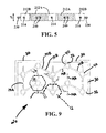
- FIG. 9 depicts an enlarged view of a portion of the wire mesh support frame of FIG. 6 .
- FIG. 10 shows an enlarged view of a portion of the view shown in FIG. 4 .
- FIG. 11 depicts a perspective view of a mold suitable for forming the implant section of FIG. 3 .
- FIG. 12 depicts an enlarged view of a portion of the mold of FIG. 11 .
- FIG. 13 depicts a perspective view of a negative mold suitable for forming the mold of FIG. 11 .
- FIG. 14 depicts top plan views of three additional embodiments of implant sections having various configurations.
- FIG. 15 depicts a portion of a further modified wire mesh support frame for use in any of the implant section embodiments described herein.
- FIG. 16A is a schematic cross-sectional view depicting an implant implanted in a patient's skull.
- FIG. 16B is a schematic cross-sectional view similar to FIG. 16A , wherein an alternative embodiment of an implant section ( 710 D) has replaced middle implant section ( 710 B) of FIG. 16A .
- FIG. 17 is a cross-sectional view of the implant section ( 710 D) of FIG. 16B , wherein the cross-sectional view is taken similarly to the cross-sectional view of FIG. 5 (i.e., across the width of the implant section).
- FIG. 18 depicts a mosaic implant ( 810 ) positioned over a defect in a patient's zygomatic (cheek) bone, and a second mosaic implant ( 811 ) positioned over a defect in a patient's mandible (chin).
- FIG. 19 depicts the process of using a mosaic implant ( 910 ) in the repair of a segmental long bone defect in a patient's femur.
- FIG. 20 is a top plan view of the wire mesh support frame used in the implant depicted in FIG. 19 .
- FIG. 21 is an enlarged top plan view of a portion of the wire mesh support frame of FIG. 20 .
- FIG. 22 is a view similar to FIG. 21 , wherein the mosaic plates of the implant are shown in combination with the wire mesh support frame.
- FIG. 23 is similar to the view shown in FIG. 9 , and depicts an alternative wire mesh support frame wherein a plurality of the wires include an expandable (or stretchable) segment or region such that the support frame is expandable in one or more directions.
- FIG. 24 depicts an enlarged portion of the wire mesh support frame of FIG. 23 .
- FIG. 25 is similar to FIG. 15 , and depicts a portion of another alternative embodiment of a wire mesh support frame for use in any of the implant section embodiments described herein.
- FIGS. 26 and 27 depict top plan views of still further embodiments of implant sections.
- FIG. 28 depicts a top view of a wire mesh support frame of a bore hole implant, wherein the biocompatible plate (e.g., a hydraulic cement) is shown in dashed line.
- the biocompatible plate e.g., a hydraulic cement
- FIG. 29 depicts a top plan view of the bore hole implant of FIG. 28 , including the round plate.
- FIG. 30 depicts an enlarged view of a portion of the wire mesh support frame of FIG. 28 .
- FIG. 31 depicts a side view of the wire mesh support frame of FIG. 28 .
- FIG. 32 depicts a side view of the bore hole implant of FIG. 29 .
- FIG. 33 depicts a top view of another embodiment of a wire mesh support frame of a bore hole implant, wherein the biocompatible plate (e.g., monetite) is shown in dashed line.
- the biocompatible plate e.g., monetite
- FIG. 34 depicts a top plan view of the bore hole implant of FIG. 33 , including the round plate.
- FIG. 35 depicts an enlarged view of a portion of the wire mesh support frame of FIG. 33 .
- FIG. 36 depicts a top view of yet another embodiment of a wire mesh support frame of a bore hole implant, wherein the biocompatible plate is shown in dashed line.
- FIG. 37 depicts a top view of a still further embodiment of a wire mesh support frame of a bore hole implant, wherein the biocompatible plate is shown in dashed line.
- Examples described herein relate to implants for use in correcting various bone defects, such as implants for use in cranioplasty procedures.
- the implants generally include a plurality of biocompatible mosaic plates that are interconnected with one another by a plurality of wires extending between adjacent plates.
- Embodiments of the implants described herein also include retention features such as a plurality of eyelets located about the periphery of the implant through which fasteners (e.g., bone screws) may be driven into bone surrounding a defect.
- the implants are configured such that the implant may be cut to various sizes while still providing the retention features about the periphery of the implant.
- an implant comprising a plurality of biocompatible mosaic plates interconnected with one another by a plurality of wires extending between adjacent plates is fabricated in a predetermined configuration that is not specific to a defect in a particular patient.
- the implant is sized and shaped (e.g., deformed into a curved shape corresponding to the shape of the defect, and/or cut to size) according to the needs of a particular patient.
- Some embodiments provide two or more implants in predetermined configurations (e.g., two or more different sizes) such that one of the implants may be selected for use in a particular patient, and then sized and shaped as necessary.
- an implant ready for implantation in a patient comprises a single section of interconnected mosaic plates.
- an implant comprises two or more implant sections that are coupled to one another in order to form an implant.
- two implant sections are coupled to one another along a beam portion that extends across a length of the implant.
- two implant sections are coupled to one another along adjacent sides such that the beam portion is provided by the coupled sides of the implant sections.
- a series of implant sections which may be identical or different in size, shape and/or configuration, are coupled together so as to form a single implant for use in a patient.
- Implants described herein are also deformable such that at least a portion of the implant is conformable to a curved surface (e.g., a spherical, spheroidal, cylindrical, etc. surface).
- a curved surface e.g., a spherical, spheroidal, cylindrical, etc. surface.
- the implant may be deformed such that the upper and lower surfaces of the mosaic plates will form a generally curviplanar surface (with small gaps between adjacent plates).
- the implant may be shaped at the time of fabrication (e.g., after molding of the mosaic plates) and/or at another time prior to implantation in a patient (e.g., in an operating room).
- some embodiments described herein include additional components and/or features which provide structural support to the curved portion of the implant so as to resist deformation of the curved portion following implantation in a patient (e.g., due to external mechanical loads). In other words, the curved surface of the implant will not flatten or cave inward in response to external mechanical loads.
- the beam portion of coupled implant sections provides such structural support.
- one or more support girders may also be provided on one or more of the implant sections and/or across an implant in order to provide similar structural support.
- Implant sections may be coupled together in any of a variety of combinations so as to allow the implant to not only conform to the desired shape (in terms of size, curvature and perimetral shape), but also span defects of considerable size.
- cranial defects e.g., regions where a patient's cranium is missing
- up to about 200 mm ⁇ about 130 mm in size with the missing portion of the cranium having a variety of curvatures, may be treated using the implants described herein.
- the term “wire” refers to a strand, rod, strut, or similar structure having a length that is relatively long compared to its width and thickness, regardless of cross-sectional shape.
- a “wire,” as used herein, can have a circular, oval, rectangular, or other cross-sectional shape.
- some of the wires of the implants do not have a constant width and/or thickness along their entire length, and may have segments or regions that are irregular in shape.
- some wires may have a pleated or crimped segment that allows the effective length of the wire to be elongated or shortened, while others have segments of reduced width and/or thickness to provide regions of greater flexibility.
- one or more wires have segments of increased width and/or thickness in order provide greater rigidity and/or support to the implant.
- An individual wire may be in the form of a single, continuous structure, or a plurality of individual filaments or strands may be combined to form a wire (e.g., wrapped or braided).
- the wires may be made from any of a variety of biocompatible materials suitable for implantation in a patient, such as various metals, polymers, or even composite materials of two or more metals and/or polymers.
- biocompatible polymers such as polycaprolactone, shape memory alloys such as nitinol, titanium, titanium alloys (e.g. Ti 6 Al 4 V) and stainless steel.
- the wires may also be formed in any of a variety of manners such as forging, casting, molding, extrusion, cutting, etching, stamping, etc.
- the wires which interconnect the mosaic plates are formed from a metal sheet (e.g., titanium) which is stamped or cut (e.g., using an automated laser cutting device) in a predetermined pattern to produce a unitary mesh of connected wires having a wire rim extending about at least a portion of its periphery.
- a metal sheet e.g., titanium
- FIGS. 1-3 depict exemplary mosaic implant sections ( 10 , 110 , 210 ) which may be used either individually or in combination in the repair of bone and other tissue defects in mammals (including human patients).
- two or more of mosaic implant sections ( 10 , 110 , 210 ), either identical sections or any combination of different sections, may be coupled together to provide a single implant.
- Any number of shapes and sizes of mosaic implant sections may be provided, and the three shown are merely exemplary of three possible configurations.
- the resulting mosaic implant is conformable to various curved shapes in order to match that of a patient's bone defect.
- two or more implant sections may be selected and coupled together to provide an implant which is sized and configured for a particular patient.
- the resulting implant comprising two or more of mosaic implant sections ( 10 , 110 , 210 ) may be configured to match a particular patient's cranial defect in terms of size, shape (e.g., perimetral shape) and, in some instances, curvature.
- a single implant section ( 10 , 110 , 210 ), optionally cut to size and shape as necessary, will be suitable for a relatively small defect in a patient. Larger defects can be treated with two or more implant sections ( 10 , 110 , 210 ) coupled together so as to provide an implant of a sufficient size for the patient's defect.
- some embodiments of coupled implant sections provide additional structural support and/or implants having a greater degree of curvature. Kits for such purposes are also described further herein.
- FIG. 4 depicts an exemplary mosaic implant ( 400 ) implanted in a skull having a very large defect.
- Mosaic implant ( 400 ) comprises five implant sections that have been coupled together along their adjacent sides.
- implant ( 400 ) comprises, from left to right, an implant section ( 210 ), another implant section ( 210 ), an implant section ( 110 ), and two implant sections ( 10 ).
- Each of the implant sections also has been trimmed in length, as further described herein.
- the far right implant section ( 10 ) also has been trimmed in width.
- implant ( 400 ) is sized and shaped to correspond to the patient's bone defect.
- implant ( 400 ) is shaped so that it generally conforms to a curved surface corresponding to the typical shape of the missing portion of patient's cranium.
- implant ( 400 ) has been shaped (i.e., deformed) to match the patient's cranial shape.
- Such shaping not only helps to ensure the maintenance of sufficient cranial volume upon bone in-growth and implant resorption, but also provides a cosmetically pleasing appearance.
- implant sections ( 10 , 110 , 210 ) are configured and coupled together such that implant ( 400 ) has high mechanical strength which, following implantation in a patient, resists deformation due to external mechanical loads.
- Implant ( 400 ) will resist flattening or caving-in due to mechanical loads or impact which might occur during normal daily activities. Without one or more of the structural support features described further herein, implant ( 400 ) would be more likely to collapse or bend inwardly as a result of an external force applied against the area of implant ( 400 ).
- Implant ( 400 ) can be attached to host tissue (e.g., the patient's cranial bone about the perimeter of a defect) via sutures, plates, screws, clamps and/or any of a variety of other fasteners or fixation devices.
- implant ( 400 ) is attached to the surrounding cranial bone using a plurality of screws (e.g., titanium bone screws) inserted through retention eyelets ( 40 , 140 , 240 ) located along portions of the periphery of the implant sections ( 10 , 110 , 210 ), as described further herein.
- screws e.g., titanium bone screws
- each implant section ( 10 , 110 , 210 ) comprises a plurality of biocompatible mosaic plates ( 12 , 112 , 212 ) which are interconnected with one another by a plurality of wires ( 14 , 114 , 214 ).
- Each mosaic plate ( 12 , 112 , 212 ) is connected to a plurality of the immediately adjacent mosaic plates by the wires ( 14 , 114 , 214 ).
- each plate ( 12 , 112 , 212 ) (or at least a majority of the plates of an implant section) is connected to two or more adjacent plates by the wires ( 14 , 114 , 214 ).
- the mosaic plates located along the side, top and bottom edges of the implant section are connected to two or three adjacent plates.
- the interior mosaic plates are connected to four of the six adjacent plates.
- wires ( 14 , 114 , 214 ) extend between and into the adjacent connected plates ( 12 , 112 , 212 ).
- wires ( 14 , 114 , 214 ) may be configured such that separate, non-intersecting, non-connected wires extend between adjacent plates.
- wires ( 14 , 114 , 214 ) comprise an arrangement of crossing wires which may or may not be connected to each other, as described in the '145 App.
- wires ( 14 , 114 , 214 ) are integrally formed with one another such as by cutting (e.g., laser cutting), etching or stamping a flat sheet in order to provide wires ( 14 , 114 , 214 ) in the form of wire segments connected to one another via retention eyelets ( 40 , 140 , 240 ) so as to provide wire mesh.
- a “mesh” comprises an arrangement of wires wherein at least two crossing wires are joined at one, some, or all of their intersections, or wherein wire segments (e.g., wires ( 14 , 114 , 214 ) are joined to one another (e.g., via eyelets ( 40 , 140 , 240 ) such that open regions are located between and bounded by adjacent wires.
- wire segments e.g., wires ( 14 , 114 , 214
- eyelets 40 , 140 , 240
- Biocompatible mosaic plates ( 12 , 112 , 212 ) can be composed of any of a variety of resorbable and/or stable (i.e., non-resorbable) biocompatible materials, including various types and/or combinations of polymers, ceramics and metals.
- the plates are composed of an osteoconductive and/or osteoinductive material. Osteoconductive materials serve as a scaffold on which bone cells will attach, migrate, and grow and divide so as to form new bone on the surfaces of the plates ( 12 , 112 , 212 ). Osteoinductive materials induce new bone formation around the plates ( 12 , 112 , 212 ).
- osteoconductive and/or osteoinductive mosaic plates will facilitate bone growth onto and between the plates of the implant ( 400 ), since the gaps allow for the free circulation of blood and tissue fluids between the plates.
- biocompatible mosaic plates are composed of a moldable bioceramic or biopolymer material. While bioceramic materials can be produced by sintering ceramic powders, it can be difficult to produce complex shapes in this manner. Alternatively, bioceramics can be formed by a chemical bonding route whereby the ceramic material is formed by chemical reaction, such as a cement setting and hardening reaction.
- a hydraulic cement composition is used to mold mosaic plates ( 12 , 112 , 212 ).
- Non-limiting examples include cement precursor compositions comprising one or more Ca-salts such as calcium sulfates, calcium phosphates, calcium silicates, calcium carbonates and combinations thereof.
- the biocompatible plates are formed by molding the cement composition around portions of the wires ( 14 , 114 , 214 ).
- a powdered cement precursor composition is combined with either a non-aqueous water-miscible liquid or a mixture of water and a non-aqueous water-miscible liquid.
- the mixture is then poured or injected into a mold having the wires ( 14 , 114 , 214 ) positioned therein, and allowed to harden (e.g., in a water-containing bath) so as to form the mosaic plates ( 12 , 112 , 212 ) interconnected to one another by the plurality of wires ( 14 , 114 , 214 ).
- cement compositions that may be used to mold mosaic plates ( 10 , 110 , 210 ) are described, for example, in U.S. Provisional Pat. App. No. 61/737,355, filed Dec. 14, 2012, titled “Cement-Forming Compositions, Cements, Implants and Methods for Correcting Bone Defects.”
- Alternative cement compositions for use in molding the plates, including storage stable premixed hydraulic cement compositions, are described in PCT App. No. PCT/IB2012/054701, filed Sep.
- compositions are calcium phosphate cement-forming compositions that comprise a monetite-forming calcium-based precursor powder and a non-aqueous water-miscible liquid.
- the monetite-forming calcium-based precursor powder comprises monocalcium phosphate (monocalcium phosphate monohydrate (MCPM) and/or anhydrous monocalcium phosphate (MCPA)) and ⁇ -tricalcium phosphate in a weight ratio of 40:60 to 60:40, and from 2 to 30 weight percent, based on the weight of the precursor powder, of dicalcium pyrophosphate powder (also referred to herein as calcium pyrophosphate).
- the powder to liquid (wt/vol) ratio in the composition is from 2 to 6 g/ml.
- the compositions are calcium phosphate cement-forming compositions that comprise a monetite-forming calcium-based precursor powder and are adapted to be mixed with an aqueous liquid or exposed to an aqueous liquid to achieve hardening.
- the monetite-forming calcium-based precursor powder comprises monocalcium phosphate (monocalcium phosphate monohydrate (MCPM) and/or anhydrous monocalcium phosphate (MCPA)) and ⁇ -tricalcium phosphate in a weight ratio of 40:60 to 60:40, and from 2 to 30 weight percent, based on the weight of the precursor powder, of dicalcium pyrophosphate powder (also referred to herein as calcium pyrophosphate).
- the molded plates ( 14 , 114 , 214 ) may thus comprise monetite and from 2 to 30 weight percent of dicalcium pyrophosphate.
- the monetite composition contains a majority of monetite, and in specific embodiments, contains at least 55 wt %, at least 60 wt %, at least 65 wt %, at least 70 wt %, at least 75 wt %, at least 80 wt %, at least 85 wt %, or at least 90 wt %, monetite.
- Such compositions results in slower implant resorption in a bone defect repair in a patient, as well as improved bone induction in a bone defect repair in a patient.
- the monetite-forming calcium-based precursor powder comprises monocalcium phosphate and ⁇ -tricalcium phosphate mixed in a weight ratio of 45:55 to 52:48, and calcium pyrophosphate powder.
- the monocalcium phosphate (monocalcium phosphate monohydrate (MCPM) and/or anhydrous monocalcium phosphate (MCPA)) is acidic and has a pH of less than 6.0.
- a 0.1 g/ml saturated aqueous solution of the monocalcium phosphate has a pH less than 3.0.
- the MCPA and MCPM should exhibit a pH of 2.5-2.8.
- the monocalcium phosphate consists essentially of MCPA, whereby significant amounts of MCPM, i.e., greater than about 25%, or greater than about 10%, or greater than about 5%, based on the weight of the monocalcium phosphate, are excluded.
- the monocalcium phosphate consists of MCPA.
- the MCPA does not contain any crystal water as is the case with mono calcium phosphate monohydrate.
- the calcium pyrophosphate (dicalcium pyrophosphate) comprises from 2 to 10 wt %, from 3 to 10 wt %, from 4 to 10 wt %, from 5 to 10 wt %, from 6 to 10 wt %, from 7 to 10 wt %, or from 8 to 10 wt %, of the precursor powder or the molded monetite composition.
- the calcium pyrophosphate comprises from 2 to 5 wt %, from 3 to 5 wt %, or from 4 to 5 wt % of the precursor powder or the monetite composition.
- the calcium pyrophosphate comprises from 3 to 8 wt %, or from 4 to 7 wt % of the precursor powder or the monetite composition.
- the calcium pyrophosphate comprises from 2 to 15 wt %, from 3 to 15 wt %, from 4 to 15 wt %, from 5 to 15 wt %, from 6 to 15 wt %, from 7% to 15 wt %, from 8 to 15 wt %, from 9 to 15 wt %, from 10 to 15 wt %, from 11 to 15 wt %, or from 12 to 15 wt %, of the precursor powder or the monetite composition.
- the calcium pyrophosphate comprises from 2 to 20 wt %, from 3 to 20 wt %, from 4 to 20 wt %, from 5 to 20 wt %, from 6 to 20 wt %, from 7 to 20 wt %, from 8 to 20 wt %, from 9 to 20 wt %, from 10 to 20 wt %, from 11 to 20 wt %, from 12 to 20 wt %, or from 15 to 20 wt %, of the precursor powder or the monetite composition.
- the calcium pyrophosphate comprises from 2 to 25 wt %, from 3 to 25 wt %, from 4 to 25 wt %, from 5 to 25 wt %, from 6 to 25 wt %, from 7 to 25 wt %, from 8 to 25 wt %, from 9 to 25 wt %, from 10 to 25 wt %, from 11 to 25 wt %, from 12 to 25 wt %, from 13 to 25 wt %, from 14 to 25 wt %, from 15 to 25 wt %, or from 20 to 25 wt %, of the precursor powder or the monetite composition.
- the calcium pyrophosphate comprises from 3 to 30 wt %, from 4 to 30 wt %, from 5 to 30 wt %, from 6 to 30 wt %, from 7 to 30 wt %, from 8 to 30 wt %, from 9 to 30 wt %, from 10 to 30 wt %, from 11 to 30 wt %, from 12 to 30 wt %, from 13 to 30 wt %, from 14 to 30 wt %, from 15 to 30 wt %, from 16 to 30 wt %, from 17 to 30 wt %, from 18 to 30 wt %, from 19 to 30 wt %, from 20 to 30 wt %, from 21 to 30 wt %, from 22 to 30 wt %, from 23 to 30 wt %, from 24 to 30 wt %, or from 25 to 30 wt %, of the precursor powder or the monetite
- the calcium pyrophosphate may comprise alpha-dicalcium pyrophosphate, beta-dicalcium pyrophosphate and/or gamma-calcium pyrophosphate.
- the calcium pyrophosphate comprises beta-dicalcium pyrophosphate.
- the calcium pyrophosphate comprises alpha-dicalcium pyrophosphate.
- the calcium pyrophosphate comprises gamma-dicalcium pyrophosphate.
- the precursor powder composition may comprise one or more additional Ca-salts selected from the group consisting of anhydrous dicalcium phosphate, dicalcium phosphate dehydrate (brushite), octacalcium phosphate, ⁇ -tricalcium phosphate, alpha-dicalcium pyrophosphate, gammadicalcium pyrophosphate, amorphous calcium phosphate, calcium-deficient hydroxyapatite, non-stoichiometric hydroxyapatite, tetracalcium phosphate, ⁇ -TCP granules, and/or combinations thereof, in minor amounts which do not change the monetite-forming quality of the precursor powder.
- additional Ca-salts selected from the group consisting of anhydrous dicalcium phosphate, dicalcium phosphate dehydrate (brushite), octacalcium phosphate, ⁇ -tricalcium phosphate, alpha-dicalcium pyrophosphate, gammadicalcium pyr
- the porosity of the molded plates ( 12 , 112 , 212 ) may also be controlled, as the porosity affects bone in-growth and the resorption time in vivo.
- porosity may be controlled by controlling monocalcium phosphate particle size in the precursor composition, and/or adding one or more porogens to the precursor composition.
- the molded plates have a porosity of from 40 to 50%, and in other embodiments the porosity is about 46%.
- a monetite-forming precursor composition comprises: (a) acidic (pH ⁇ 6) monocalcium phosphate (monocalcium phosphate monohydrate (MCPM) and/or anhydrous monocalcium phosphate (MCPA)); (b) ⁇ -tricalcium phosphate; and (c) 2-30 wt. % dicalcium pyrophosphate powder (also referred to as calcium pyrophosphate), based on the total weight of the precursor powder.
- the weight ratio of monocalcium phosphate to ⁇ -tricalcium phosphate is between 40:60 and 60:40. It will also be understood that the monocalcium phosphate portion of the precursor composition may include a small amount of monetite (e.g., 8-12%, based on the weight of the precursor powder).
- the above-described combination of calcium phosphates (e.g., in the form of a powder mixture) is then mixed with a non-aqueous water-miscible liquid such as glycerol at a powder to liquid (g/ml) ratio of from 2 to 6.
- the liquid portion optionally may include up to 20% water (based on the total liquid volume).
- the precursor mixture is injected into a mold having the wires ( 14 , 114 , 214 ) positioned therein, with portions of each wire extending into and between the mold cavities which are shaped to form the mosaic plates ( 12 , 112 , 212 ).
- the filled mold is then exposed to water, such as by placing the mold in a water bath, and the cement is allowed to harden (e.g., 24 hours in a room temperature water bath).
- the implant section ( 10 , 110 , 210 ) is then removed from the mold. Further processing such as soaking the implant section in water to remove glycerol residues may be performed, as necessary.
- the thus-formed mosaic plates ( 12 , 112 , 212 ) in the example described above will comprise monetite (CaHPO 4 ) and 2-30 wt. % dicalcium pyrophosphate, along with varying amounts of other materials such as ⁇ -tricalcium phosphate and minor amounts of brushite (CaHPO 4 .2H 2 O) (e.g., less than 2 wt. % or less than 1 wt. %).
- the mosaic plates ( 12 , 112 , 212 ) in some embodiments comprise at least 65 wt %, at least 70%, at least 75%, at least 80%, at least 85%, or at least 90% monetite. As further discussed in U.S. Prov. Pat.
- Each mosaic plate ( 12 , 112 , 212 ) may have any of a variety of shapes, such as triangles, circles, squares, rectangles, pentagons, hexagons, or other polygons.
- the shape of each plate may be regular (e.g., a pentagon or hexagon having sides of equal length) or irregular.
- the plates ( 12 , 112 , 212 ) of an implant section ( 10 , 110 , 210 ) may have the same or different shapes, regular and/or irregular.
- the plates ( 12 , 112 , 212 ) have identical shapes (e.g., regular hexagons, squares or rectangles) and are arranged in a pattern such that each side edge of a plate is spaced apart from an edge of an immediately adjacent plate by the same (or nearly the same) amount so that a consistent gap is provided between adjacent plates.
- adjacent plates may nevertheless have complementary shapes such that the plates are arranged in a pattern with no overlap of plates and substantially equal gaps between adjacent plate edges.
- each implant section ( 10 , 110 , 210 ) includes both hexagonal ( 12 A, 112 A, 212 A) and pentagonal plates ( 12 B, 112 B, 212 B).
- the mosaic plates are arranged in five columns extending lengthwise along the length (L) of the implant section ( 10 , 110 , 210 ).
- the columns of plates are staggered such that consistent gaps are provided between the edges of adjacent plates, as shown.
- each column is shifted from an adjacent column in the lengthwise direction by slightly more than 1 ⁇ 2 the width of an individual plate.
- the plates ( 12 A, 112 A, 212 A) of the center three columns are in the shape of hexagons, each of approximately the same dimensions except for truncated plates ( 12 C, 112 C, 212 C) located near the center of the implant section ( 10 , 110 , 210 ).
- Truncated plates ( 12 C, 112 C, 212 C) are truncated along their edges adjacent a support girder ( 250 ) which extends across the width (W) of the implant sections (as discussed further herein).
- the plates ( 12 B, 112 B, 212 B) in the outermost columns are in the shape of irregular pentagons.
- the outermost edges of plates ( 12 B, 112 B, 212 B) i.e., the edge adjacent the right and left sides of the implant sections) are aligned with one another in a linear ( FIG. 1 ) or curvilinear ( FIGS. 2 and 3 ) fashion.
- a wire rim extends about the entire periphery of the implant section ( 10 , 110 , 210 ), and is connected to plates ( 12 B, 112 B, 212 B) as well as support girder ( 50 , 150 , 250 ) via wire struts ( 32 , 132 , 232 ) which extend between the rim ( 30 , 130 , 230 ) and outer plates ( 12 B, 112 B, 212 B) (as well as between the rim and the ends of the support girders).
- the outermost edges of pentagonal outer plates ( 12 B, 112 B, 212 B) are aligned with, and spaced inwardly from, wire rim ( 30 , 130 , 230 ), as shown in FIGS. 1-3 .
- the wire rim ( 30 , 130 , 230 ) may extend about only a portion of the periphery of the implant section, such as along either side thereof.
- implant section ( 10 ) On implant section ( 10 ), the right and left sides of rim ( 30 ), and hence the right and left sides of the implant section ( 10 ) are parallel such that implant section ( 10 ) has a rectangular shape.
- implant sections ( 110 , 210 ) on the other hand, the right and left sides of rim ( 130 , 230 ) are curvilinear such that the implant section ( 110 , 210 ) has the shape of a curved rectangle—the right and left sides are symmetrically curved, while the top and bottom ends are parallel.
- implant sections ( 110 , 210 ) are widest at their center (i.e., where support girder ( 150 , 250 ) is joined to rim ( 130 , 230 ), and symmetrically taper in width towards each end.
- the sides of an implant section may be linearly tapered rather than curvilinearly tapered. In such embodiments, are still widest at their center, but symmetrically taper in width towards each end along straight lines.
- only one side of an implant section may taper (linearly or curvilinearly).
- one or both sides of an implant section may be tapered along only a portion of its length. For example, the sides of an implant section may taper in width from support girder ( 50 , 150 , 250 ) towards only the top or bottom ends.
- Implant section ( 210 ) differs from implant section ( 110 ) in that implant section ( 210 ) is wider at support girder ( 250 ). In other words, the right and left sides of rim ( 230 ) of implant section ( 210 ) are more curved than the right and left sides of rim ( 130 ) of implant section ( 110 ). Additionally, in the depicted embodiments, implant sections ( 10 , 110 , 210 ) all have substantially the same width at their top and bottom ends. As will be discussed further herein, the varying configurations of implant sections ( 10 , 110 , 210 ) allow the implant sections to be coupled in a variety of arrangements in order to provide an implant ( 400 ) of a variety of different curvatures. Thus, any number of implant sections of additional shapes and configurations may be provided (e.g., one with sides having even greater curvature than implant section ( 210 )) so as to enable additional combinations of implant sections for matching various bone defects.
- Implant sections ( 10 , 110 , 210 ) may be provided in any of a variety of sizes.
- implant section ( 10 ) has a width W of about 39 mm and a length L of about 150 mm.
- Implant section ( 110 ) has a width of about 45 mm at its center (i.e., at support girder ( 150 )) and 37 mm at the top and bottom ends, and a length of about 148 mm.
- Implant section ( 210 ) has a width of about 50 mm at its center (i.e., at support girder ( 150 )) and 35 mm at the top and bottom ends, and a length of about 148 mm.
- these sizes are merely exemplary, as any of a wide variety of sizes and curvatures/tapers may be provided in the implant sections.
- Mosaic plates ( 12 , 112 , 212 ) may be provided in any of a variety of sizes.
- mosaic plates ( 12 A, 112 A, 212 A) shown in FIGS. 1-3 have a width (W T ) of approximately 8 mm at their bottom surface and approximately 8.4 mm at their top surface, wherein the plate width is defined as the distance between opposite, parallel sides of a plate.
- W T the width of the mosaic plates ( 12 A, 112 A, 212 A) are sloped or tapered such that the plates are wider at their top surface than at their bottom surface (e.g., as depicted in FIG. 5 ).
- the thickness of mosaic plates ( 12 A, 112 A, 212 A) is approximately 4 mm (as depicted by distance T T in FIG. 5 ).
- the gap between adjacent edges of plates ( 12 , 112 , 212 ) at the bottom surface of the plates is approximately 1 mm, and approximately 0.6 mm at the top surface.
- the mosaic plates ( 212 A) particularly those of the first and third columns, have varying sizes such that the plates ( 212 A) at the ends of the implant section have a width of approximately 7.5 mm at their bottom surface and approximately 7.9 mm at their top surface.
- the plates ( 212 A) at the middle of implant section ( 210 ) have a width of approximately 8.7 mm at their bottom surface and approximately 9.1 mm at their top surface.
- these dimensions are merely exemplary of one embodiment, as any of a variety of plate sizes and spacings may be used.
- the sidewalls of the mosaic plates may be sloped or tapered such that the plates are wider at their top surface than at their bottom surface.
- this sloping or tapering may be configured in a variety of other manners, such as tapering the sidewalls of the mosaic plates from both the top and bottom surfaces so that the plates are widest in cross-section across the center of the plate, or at some other location between the top and bottom surfaces.
- the sloping or tapering of the sidewalls allows the implant section to be deformed into various curvatures, with a deeper concavity in the bottom surface of the implant without the edges of adjacent mosaic plates coming into contact with each other than would be possible with vertical, non-tapered sidewalls.
- the top surface width W T of each plate is between 2 and 20 mm, between 3 and 15 mm, or between 4 and 10 mm.
- the mosaic plates have a thickness T T which is between 10% and 150% of W T , between 20% and 80% of W T , or between 30% and 60% of W T .
- the thickness T T is as small as possible while maintaining sufficient strength of the plates.
- the thickness T T can be reduced by polishing or other material removal process, particularly along the periphery of the implant in order to improve implant fit and improve aesthetics (e.g., to provide a smooth, reduced height transition between the surface of surrounding bone and the upper surface of the implant).
- the gap between adjacent edges of plates at the bottom surface of the plates is less than 3 mm, less than 2 mm, or less than 1.2 mm.
- a smaller gap facilitates the filling of the gap by new bone growth.
- a smaller gap will inhibit the amount of deformation (i.e., curvature) which is possible when matching the implant to a patient's defect.
- curvature the amount of deformation which is possible when matching the implant to a patient's defect.
- having a larger gap allows the implant to be deformed more before adjacent plates contact each other, but larger gaps between plates also take a longer time to fill with new bone growth. It is of course possible to have different sized gaps between cavities if the implant is intended to have regions which will be substantially flat and other regions which will be deformed into various curvatures and shapes.
- wire rim ( 30 , 130 , 230 ) which extends about the periphery of implant sections ( 10 , 110 , 210 ) is connected to plates ( 12 B, 112 B, 212 B) as well as support girder ( 50 , 150 , 250 ) via wire struts ( 32 , 132 , 232 ).
- mosaic plates ( 12 , 112 , 212 ) are interconnected with one another by a plurality of wires ( 14 , 114 , 214 ) which extend between adjacent plates.
- a single wire extends between each connected pair of adjacent plates.
- two or more wires may extend between each connected pair of adjacent plates, as shown and described in the '145 App.
- Wires ( 14 , 114 , 214 ) may comprise separate, non-intersecting, non-connected wires which extend between and into adjacent plates—i.e., as individual wire segments.
- wires ( 14 , 114 , 214 ) may comprise crossing wires which may or may not be connected to each other, as described in the '145 App. In such arrangements, each wire may extend from one side or end of the implant section to the opposite side or end, such that each wire interconnects multiple pairs of adjacent plates.
- wires ( 14 , 114 , 214 ) are interconnected with one another via retention eyelets ( 40 , 140 , 240 ), some of which are also connected to rim ( 30 , 130 , 230 ) by wire struts ( 32 , 132 , 232 ).
- the resulting structure is a wire mesh support frame ( 20 , 120 , 220 ) which is bounded about at least a portion of its periphery by rim ( 30 , 130 , 230 ), as shown in FIGS. 6-8 .
- Support frame ( 20 , 120 , 220 ) may be formed in a variety of ways such as by welding wire segments and eyelets to one another in the arrangement shown, or by a molding process.
- the components of support frames ( 20 , 120 , 220 ) are integrally formed with one another by cutting (e.g., laser cutting), etching or stamping a flat sheet to form wires ( 14 , 114 , 214 ), eyelets ( 40 , 140 , 240 ), wire struts ( 32 , 132 , 232 ), support girder ( 50 , 150 , 250 ) and rim ( 30 , 130 , 230 ) from a single sheet of material.
- support frames ( 20 , 120 , 220 ) are laser cut, using an automated, programmable laser cutting device, from a sheet of titanium.
- the titanium sheet comprises grade 2, 4 or 5 titanium, 0.3-0.6 mm thick. In the embodiment shown, grade 2 titanium, 0.4 mm thick is used.
- support frame ( 20 , 120 , 220 ) may be cut, etched, stamped, molded or otherwise formed from a biodegradable polymer such as polycaprolactone.
- eyelet means an opening having a substantially closed perimeter, but it is not limited to a particular shape.
- eyelets ( 40 , 140 , 240 ) can be round, square, rectangular, trapezoidal, hexagonal, tear-drop, oval, elliptical or any other suitable shape.
- other types of attachment apertures or other fastening points may be used in place of, or in addition to the eyelets ( 40 , 140 , 240 ).
- each mosaic plate ( 12 , 112 , 212 ) is connected to a plurality of the immediately adjacent mosaic plates by the wires ( 14 , 114 , 214 ). Except for those located along the top and bottom ends of the implant section, the interior plates ( 12 A, 112 A, 212 A) of the center three columns of plates are connected to four of the six adjacent plates. The plates ( 12 A, 112 A, 212 A) of the center three columns located along the top and bottom ends are connected to three of the five adjacent plates. Similarly, except for those located along the top and bottom ends of the implant section, the plates ( 12 B, 112 B, 212 B) in the outermost columns are connected to three of four adjacent plates. Finally, the plates ( 12 B, 112 B, 212 B) of the outermost columns located along the top and bottom ends are connected to two of the three adjacent plates.
- Each eyelet ( 40 , 140 , 240 ) is positioned so as to be located entirely within the interior of a plate ( 12 , 112 , 212 ), such as approximately in the middle of the plate.
- wires ( 14 , 114 , 214 ) extend away from eyelets ( 40 , 140 , 240 ) so as to span between the adjacent, parallel sides of adjacent plates.
- wires ( 14 , 114 , 214 ) intersect the sides of the plates at an angle of approximately 90°, as best seen in FIG. 9 .
- vertical wires ( 14 A, 114 A, 214 A) extend approximately parallel to the sides of the implant sections, in five straight or slightly curved columns.
- wires ( 14 A) extend in five parallel columns that are also parallel to the left and right sides of implant section ( 10 ).
- the center column of wires ( 114 A, 214 A) extend parallel to the left and right sides of implant section ( 110 , 210 ), while the other columns of wires ( 114 A, 214 A) are slightly curved to approximately match the curved sides of these implant sections ( 110 , 210 ), the outermost columns of wires ( 114 A, 214 A) are slightly more curved than the columns spaced inwardly therefrom, but slightly less than the curvature of rim ( 130 , 230 ) along the right and left sides of the implant sections ( 110 , 210 ).
- wire struts ( 132 , 232 ) of implant sections ( 110 , 210 ) increase slightly in length progressing from the top and bottom ends towards support girder ( 150 , 250 ).
- each wire ( 14 B, 114 B, 214 B) is arranged in a zigzag fashion across the width of the implant section ( 10 , 110 , 210 ), as shown.
- each wire ( 14 B, 114 B, 214 B) extends from an eyelet ( 40 , 140 , 240 ) at an included angle of about 60° to one adjacent wire ( 14 A, 114 A, 214 A) extending from the same eyelet, and at an included angle of about 120° to the other adjacent wire ( 14 A, 114 A, 214 A) extending from the same eyelet.
- Each eyelet ( 40 , 140 , 240 ) therefore has four wires extending therefrom, either in the form of wires ( 14 , 114 , 214 ) or wires ( 14 , 114 , 214 ) in combination with wire struts ( 32 , 132 , 232 ).
- the wires ( 14 , 114 , 214 ), struts ( 32 , 132 , 232 ), eyelets ( 40 , 140 , 240 ), and rim ( 30 , 130 , 230 ) will generally have the same thickness.
- the support frame members have a thickness of about 0.4 mm.
- the rim ( 30 , 130 , 230 ) has a width of 0.4 to 1.6 mm, or from 0.6 to 1.2 mm, or 1.0 to 1.2 mm.
- Wires ( 14 , 114 , 214 ) have a width of 0.4 to 0.6 mm
- wire struts ( 32 , 132 , 232 ) have a width of about 0.45 mm
- the interior diameter of eyelets ( 40 , 140 , 240 ) is approximately 2.1 mm
- the width of the metal forming the eyelets is about 0.4 mm.
- the wires ( 14 , 114 , 214 ) include deformation zones.
- the deformation zones are generally located in the middle of the length of a wire ( 14 , 114 , 214 ) such that they will generally be positioned between adjacent plates so that deformation will occur between the plates so as to prevent cracking of the plates upon deformation of the implant section.
- wires ( 14 , 114 , 214 ) include two different types of deformation zones.
- Wires ( 14 A, 114 A, 214 A) have reduced-width regions ( 15 A, 115 A, 215 A) which are located between adjacent plates following molding.
- wires ( 14 A, 114 A, 214 A) will deform (i.e., bend) at reduced-width regions ( 15 A, 115 A, 215 A) so that such deformation is less likely to cause the plates to crack.
- wires ( 14 A, 114 A, 214 A) have a width of 0.5 to 0.7 mm
- reduced-width regions ( 15 A, 115 A, 215 A) have a width of 0.3 to 0.5 mm. It should be understood that “transverse” is not intended to mean at an angle of 90 degrees.
- wires ( 14 B, 114 B, 214 B) have pleated regions ( 15 B, 115 B, 215 B) which are also located between adjacent plates following molding.
- Pleated regions ( 15 B, 115 B, 215 B) not only have a reduced width, they also include one or more pleats which allow additional deformation of the implant while avoiding cracking the plates.
- pleated regions ( 15 B, 115 B, 215 B) facilitate lateral deformation of the implant section (i.e., curving the implant section about an axis that extends transverse to width W, as indicated by D LAT in FIG. 4 ).
- Wires ( 14 B, 114 B, 214 B) will deform (i.e., bend) at pleated regions ( 15 B 115 B, 215 B) rather than within the plates in order to avoid plate cracking.
- pleated regions ( 15 B 115 B, 215 B) also allow the implant section to be locally stretched or compressed at pleated regions ( 15 B 115 B, 215 B) in order to further facilitate shaping of the implant to match a patient's defect.
- pleated regions ( 15 B 115 B, 215 B) also allow for some adjustment of the retention eyelets ( 40 , 140 , 240 ) located along the top and bottom edges of the implant so as to properly locate these eyelets with respect to the bone surrounding a defect. In this manner, the eyelets can be repositioned somewhat to ensure that a screw or other fastener driven therethrough in to the surrounding bone will have sufficient purchase.
- rim ( 30 , 130 , 230 ) generally can only be deformed along its length
- struts ( 32 , 132 , 232 ) are deformable along their length.
- Support girder ( 50 , 150 , 250 ) is deformable in a similar fashion.
- two or more implant sections may be coupled to one another along portions of their rims ( 30 , 130 , 230 ). Such coupling may be accomplished in any or variety of ways, such as using mechanical fasteners, biocompatible adhesives, welding, binding, etc. In the embodiments shown in FIGS. 4 and 10 , the implant sections are coupled to one another by spot welding.
- the rims ( 30 , 130 , 230 ) extending along the sides of adjacent implant sections ( 10 , 110 , 210 ) are positioned in overlapping arrangement and then welded to one another at spot welds ( 431 ) along the length of the overlapping rims.
- a “developable surface” is one that that can be flattened onto a plane without the need for any stretching or compression.
- One advantage of implant sections ( 110 , 210 ) which have curved rims ( 130 , 230 ) along their sides is that the implant sections may be attached to one another (or to implant section ( 10 )) along with adjacent sides to provide a shape which more closely matches a non-developable curved surface, much that way that various map projections are used to approximate the curvature of the earth in a flat plane.
- the implant section when the rim ( 130 ) of an implant section ( 110 ) is coupled along its length to the rim ( 230 ) of an implant section ( 210 ), the implant section will be, and in fact must be, deformed in both the D LONG and D LAT directions, as seen in FIG. 4 . Most of the curvature in the D LAT direction will result from deformation (i.e., bending of the struts ( 132 , 232 )), but this still allows implant ( 400 ) to be deformed so that the implant ( 400 ) is more conformable to a curved surface such as a sphere or spheroid or similar shapes corresponding to various regions of a cranium.
- rims ( 30 , 130 , 230 ) of implant sections ( 10 , 110 , 210 ) are coupled to one another, particular when done in an overlapping fashion, the rims of adjacent implant sections provide a beam portion extends across the length of the implant.
- This beam portion provides additional structural support to the curved implant ( 400 ) which resists deformation (e.g., flattening of the curved shape) following implantation in a patient.
- support girder ( 50 , 150 , 250 ) also provides additional structural support across the central region of implant ( 400 ), often the most vulnerable area in terms of inward deformation (i.e., flattening or caving-in).
- additional structural supports may be provided such as additional support girders extending across the width of an implant section.
- the beam portion extending across a length of the implant may be provided in various alternative ways besides adjoining rims extending along the sides of coupled implant sections.
- rim ( 30 , 130 , 230 ) itself provides structural support that resists inward deformation of a single implant section ( 10 , 110 , 210 ) which is implanted in a patient.
- one or more support girders similar to support girder ( 50 , 150 , 250 ) may be provided in the lengthwise direction, particularly in an arrangement wherein the support girder(s) is positioned in a zigzag arrangement between adjacent plates.
- additional support girders extending across the implant sections may also be provided at various desired locations.
- a separate support girder may be provided, with implant sections coupled to the support girder along either side thereof.
- implant sections ( 10 , 110 , 210 ) may be formed by a variety of processes, such as molding.
- implant sections ( 10 , 110 , 210 ) are formed by molding plates ( 12 , 112 , 212 ) about the wires ( 14 , 114 , 214 ) of a support frame ( 20 , 120 , 220 ).
- One such mold ( 510 ) is shown in FIGS. 11 and 12 , wherein the mold ( 510 ) is configured for use in forming implant section ( 210 ).
- Mold ( 510 ) may be formed of any of a variety of materials such as silicone, Teflon, other polymers or metals.
- Mold ( 510 ) includes a plurality of cavities ( 512 ) shaped and arranged for forming mosaic plates ( 212 ).
- cavities ( 512 ) have tapered sidewalls corresponding to the tapered sidewalls of the plates, as shown in FIG. 5 .
- the bottom ( 513 ) of each cavity ( 512 ) corresponds to the bottom surface of a plate ( 212 ).
- Channels ( 514 ) are provided in the sidewalls of selected cavities ( 513 ). Cavities ( 514 ) correspond to the locations of wires ( 214 ) of support frame ( 220 ) and have depth corresponding to the desired depth of the wires ( 214 ) in the implant section ( 210 ). Thus, channels ( 514 ) receive wires ( 214 ) therein. Circular cutouts ( 540 ) are also provided at the top and bottom ends of the mold to accommodate the eyelets ( 240 ) of support frame ( 220 ) which are not to be enclosed by plates ( 212 ), along with elongate grooves ( 541 ) which extend from cutouts ( 540 ) to the adjacent cavities ( 512 ).
- Elongate grooves ( 541 ) accommodate the wires ( 214 ) which extend away from eyelets ( 240 ). Similar, groove ( 550 ) extends across the width of the mold ( 510 ) for accommodating support girder ( 250 ) therein.
- a support frame ( 220 ) Prior to molding, a support frame ( 220 ) is positioned within mold ( 510 ) such that rim ( 230 ) extends about outer wall ( 515 ) of the mold cavities ( 512 ), with wires ( 214 ) positioned at the bottom of channels ( 514 ) and eyelets positioned within cutouts ( 540 ). The positioning of the wires ( 214 ) of support frame ( 220 ) is controlled by the depth of cutouts ( 540 ).
- the precursor cement composition described previously is inserted into the mold cavities ( 512 ) such as by pouring or injecting.
- mold ( 510 ) does not require a top plate
- other embodiments of mold ( 510 ) may include a top plate for enclosing the mold either before or after addition of the precursor composition. If the mold is sealed prior to the addition of the cement composition, the mold will include one or more sprues through which the cement may be injected into the mold cavities.
- the implant section ( 210 ) is removed from mold ( 510 ). Thereafter, the implant section ( 210 ) is cut to the desired length and width, as necessary. For example, as best seen in FIGS. 4 and 10 , the portion of the rim ( 30 , 130 , 230 ) extending across the top and bottom ends of the implant section is cut off along with portions of the rim extending along the sides of the implant section as necessary.
- wires ( 14 , 114 , 214 ), particularly longitudinally extending wires ( 14 A, 114 A, 214 A) may be cut as necessary, to trim the implant section to the desired length.
- laterally extending wires may be cut as necessary, particularly to trim in implant section to the desired width, as seen on the far right side of FIG. 4 .
- eyelets 40 , 140 , 240
- the mosaic plate material along the periphery of the implant is also removed such as by breaking the plates off of the support frame using pliers or other suitable implement in order to expose one or more of the eyelets about the periphery of the implant ( 400 ), as also seen in FIG. 4 .
- mold ( 510 ) comprises silicone or other moldable material.
- FIG. 13 depicts a negative mold ( 610 ) which may be used to form mold ( 510 ) by a molding process.
- FIG. 14 depicts top plan views of three additional embodiments of implant sections having various configurations.
- the implant section of FIG. 14A is similar to implant section ( 110 ), however only three columns of mosaic plates are provided and one side of the wire mesh support frame has been omitted such that no rim is provided along that side of the implant. Instead, the rimless side of the implant includes a plurality of the retention eyelets. Effectively, wire mesh support frame ( 120 ) has been cut between the fourth and fifth columns of retention eyelets. This provides a narrower implant section suitable for use along an edge of a defect, as the eyelets may be used to secure the implant section in place.
- FIG. 14B is similar to implant section ( 210 ), but considerably shorter with no rim along the ends of the implant section—only retention eyelets.
- the implant section of FIG. 14C is similar to that of FIG. 14A , only considerably shorter and with no rim extending along the ends or one side of the implant section.
- These various alternative shapes and configurations reduce waste as less material (particular the cement material) will be discarded, and are particularly suitable for use along an edge of a defect.
- these implant sections shown in FIG. 14 together with those previously described may have width of about 20 to about 60 mm, and lengths of about 60 to about 200 mm, as well as varying amounts of curvature or even irregular shapes.
- the opposing sides of the implant section may be the same direction of curvature, along with a greater degree of curvature (e.g., a curved implant section having a constant width rather than the width tapering towards the ends as shown, for example, in FIG. 3 ).
- the curvature may even vary along the length of the implant section.
- FIG. 15 depicts a portion of a further modified wire mesh support frame for use in any of the implant section embodiments described previously herein or described hereafter.
- wire rim ( 330 ) includes a plurality of enlarged or widened regions ( 331 ) spaced along at least portions of the length of rim ( 330 ), particularly along the longitudinally extending sides of rim ( 330 ).
- Enlarged regions ( 331 ) can have any of a variety of shapes, sizes and locations, and that shown is merely exemplary of one embodiment. Regions ( 331 ) serve as fastening points for facilitating the attachment of two implant sections to one another along adjacent wire rims.
- Enlarged regions ( 331 ) this provide additional surface area at these fastening points, whereat the implant sections are attached to one another such as by using mechanical fasteners, biocompatible adhesives, welding, binding, etc.
- regions ( 331 ) provide welding spots that facilitate spot welding of one implant section to another by providing an enlarged weld contact area between implant sections.
- Regions ( 331 ) may be incorporated into any of the previously described implant section embodiments along one or of the rims of the wire mesh support frame, and at one or more locations on such rims.
- enlarged regions ( 331 ) on rim ( 330 ) are provided along one or more of vertical wires ( 314 A) which extend between adjacent retention eyelets ( 340 ).
- a pair of enlarged regions ( 316 ) are provided on each vertical wire ( 314 A), with each of the enlarged regions ( 316 ) located between the deformation zones provided by reduced-width regions ( 315 A) and one of eyelets ( 340 ), as shown.
- enlarged regions ( 316 ) may be provided on vertical wires ( 314 A), and one or more enlarged regions ( 316 ) may be provided on all or only a portion of vertical wires ( 314 A). It is also contemplated that enlarged regions ( 316 ) may be provided instead of enlarged regions ( 331 ) on rim ( 330 ). Enlarged regions ( 316 ) serve the same purpose as enlarged regions ( 331 ), namely serving as fastening points (e.g., welding spots) which facilitate attachment of one implant section to another such as by providing an enlarged weld contact area between the implant sections.
- fastening points e.g., welding spots
- Enlarged regions ( 316 ) on vertical wires ( 314 A) are particularly useful for spot welding implant sections such as those shown in FIGS. 14A and 14C to one another.
- enlarged regions enlarged regions ( 316 ) still provide welding spots for facilitating spot welding of one implant section to another by providing an enlarged weld contact area between implant sections (e.g., for welding two implant sections of FIGS. 14 A and/or 14 C to one another).
- Enlarged regions ( 316 ) can have any of a variety of shapes, sizes and locations, and that shown is merely exemplary of one embodiment. Regions ( 316 ) may be incorporated into any of the previously described implant section embodiments, as well those described below.
- FIG. 25 depicts enlarged regions ( 531 ) which have an elongated oval shape.
- enlarged regions ( 531 ) which have an elongated oval shape.
- fastening points e.g., welding spots
- the oval shape allows for additional slight curvature changes in the assembled implant.
- the increased length of the enlarged regions ( 531 ), both outwardly and inwardly from the rim, allow adjacent implant sections to be attached to one another such that their adjoining rims do not precisely overlap one another, for example.
- the thickness T T of the mosaic plates can be reduced by polishing or other material removal process, particularly along the periphery of the implant in order to improve implant fit and/or improve aesthetics. This may also be accomplished by forming the mosaic plates of an implant section to have varying thickness across the mosaic plates and/or across the implant section itself, such as by configuring a mold for the mosaic plates of the implant section accordingly.
- FIG. 16A depicts a schematic cross-sectional view of an exemplary mosaic implant ( 700 ) secured to a patient's skull over the area of a very large defect.
- mosaic implant ( 700 ) comprises three implant sections ( 710 A, 710 B, 710 C) which have been coupled together along their adjacent sides.
- Implant sections ( 710 A, 710 B, 710 C) may be configured similarly to any of the implant sections previously described herein. As seen in FIG.
- the thickness of the mosaic plates may vary across the width and/or length of the implant section.
- center implant section ( 710 B) of FIG. 16A has been replaced by an implant section ( 710 D) having mosaic plates which taper in thickness across the width of the implant.
- the mosaic plates at the center of the implant section are crowned, as shown, and the mosaic plates on either side thereof taper in thickness as shown.
- the mosaic plates of implant section ( 710 D) are thickest at the middle of the implant section and narrowest at the outer sides of the implant section.
- the mosaic plates may taper in the lengthwise direction and or in one more other directions so as to better match the shape of the bone surrounding a patient's defect.
- FIG. 17 depicts a cross-sectional view of implant ( 710 D), taken along the same line as that shown in FIG. 5 .
- the additional reference numerals in FIG. 17 refer to the same components of like numerals in the preceding implant section embodiments (e.g., eyelet ( 740 ) and wires ( 714 ).
- eyelet ( 740 ) and wires ( 714 ) are adjacent implant section embodiments.
- FIG. 18 depicts an implant ( 810 ) configured for use in repairing, restoring or augmenting a patient's zygomatic bone (cheek bone).
- Implant ( 810 ) is configured similar to implant section ( 10 ) described previously, but cut and shaped to the appropriate size (e.g., by cutting off unneeded portions of support frame ( 20 ) and removing or not molding unneeded mosaic plates ( 12 )).
- implant ( 811 ) in FIG. 18 is configured for use in repairing, restoring or augmenting a patient's mandible (chin).
- implant ( 811 ) may be formed from an implant section ( 10 ) which is shaped and configured in the desired size and shape.
- implants constructed in the manner described herein may be shaped and configured for any of a variety of other bones of a patient.
- the implants described herein may also be used to treat segmental bone defects, such as those occurring in long bones (e.g., a patient's femur).
- the implant e.g., a single implant section
- the implant is wrapped around the bone defect and secured in place in the manner previously described (e.g., using screws). Any of the previously-described implants and implant sections may be used for this purpose.
- the hexagonal mosaic plates ( 12 , 112 , 212 ) may be replaced by staggered columns of rectangular mosaic plates.
- FIG. 19 depicts the process of wrapping an implant ( 910 ) around a segmental long bone defect in a femur.
- FIGS. 20 and 21 depict an alternative arrangement particularly suited for use in segmental long bone defects.
- the wire mesh support frame ( 920 ) is configured as a rectangular grid with wires ( 914 ) extending in either a horizontal or vertical direction, as shown.
- retention eyelets ( 940 ) are not located at every intersection of wires ( 914 ). Instead, there are wire crossing regions located between adjacent eyelets ( 940 ). As shown in FIG.
- mosaic plates ( 912 ) are located not only at eyelets ( 940 ) but also at the locations where wires ( 914 ) meet in a cross as well as the locations where a wire ( 914 ) intersects rim wires ( 930 ) which extend between the eyelets ( 940 ) located about the periphery of the implant ( 910 ).
- the eyelets ( 940 ) along one or more sides of the implant ( 910 ) may be left exposed (i.e., not enclosed or covered by a mosaic plate) such that these eyelets may be used to secure implant ( 910 ) to the patient's bone as shown in FIG. 19C (e.g., using one or more screws).
- the eyelets ( 940 ) along the top and bottom edges of implant ( 910 ) are exposed, with mosaic plates ( 912 ) located between adjacent pairs of such eyelets.
- Wires ( 914 ) of implant ( 910 ) also includes reduced-width deformation zones ( 915 ), as shown and as described previously. It is also contemplated that the wires ( 914 ) may have different widths and/or thicknesses to provide additional rigidity and support. For example, vertically extending wires ( 914 A) may be wider and/or thicker than horizontally extending wires ( 914 B) such that additional rigidity is provided in the direction parallel to the length of the long bone being repaired. Similarly, one or more support girders, as described previously may extend between adjacent columns or rows of mosaic plates in order to similarly provide rigidity and/or support, particularly in a direction parallel to the length of the long bone being repaired. It will be understood that any of the previously described materials and compositions, as well as manufacturing methods may be used for implant ( 910 ) as well as the implant described below.
- FIGS. 23 and 24 depict a further modified embodiment wherein deformation zones comprising a stretchable segment or region ( 1019 ) are provided on one or more of the wires ( 1014 ) of wire mesh support frame ( 1020 ).
- These stretchable segments ( 1019 ) comprise a plurality of pleats or crimps ( 1021 ), with three such pleats provided in the example shown.
- An implant formed using wire mesh support frame ( 1020 ) with mosaic plates ( 1012 ) formed thereon such that stretchable segments ( 1019 ) extend therebetween is particularly advantageous for use in children whose bones are still growing. Once implanted, as the patient's bone grows, the stretchable segments will expand along with the growing bone (particularly when portions or all of the outer rim of the wire mesh support frame are removed).
- the number and size of the pleats or crimps ( 1021 ) may be varied depending on the age of the patient, with more pleats or crimps ( 1021 ) used in implant for young children whose bones will be expected to grow more substantially, as additional pleats or crimps will allow for even greater expandability. It will also be understood that the stretchable segments may be provided on some or all of the wires ( 1014 ), depending on the anticipated direction of bone growth. In the example shown, the wire mesh support frame can expand lengthwise, widthwise and at angles parallel to the direction of wires ( 1014 B).
- FIGS. 26 and 27 depict still further alternative embodiments of implant sections ( 1210 , 1310 ). These implant sections are constructed similarly to those previously described herein, such as implant sections ( 10 , 110 , 210 ) and include various features of similar reference numerals in FIGS. 1-10 . Implant sections ( 1210 , 1310 ) may also be fabricated in the manners described previously herein.
- implant section ( 1210 ) includes only four columns of mosaic plates—two interior columns of hexagonal plates ( 1212 A) and two outer columns of pentagonal plates ( 1212 B). As before, the columns of plates are staggered such that consistent gaps are provided between the edges of adjacent plates, as shown.
- Implant section ( 1310 ) includes only three columns of mosaic plates—one interior columns of hexagonal plates ( 1312 A) and two outer columns of pentagonal plates ( 1312 B).
- Implant sections ( 1210 , 1310 ) provide additional configurations for assembled implants, as these implant sections ( 1210 , 1310 ) may be combined with any of the implant sections ( 110 , 210 , 310 ) previously described herein.
- implant section ( 1210 ) has a width of about 41 mm at its center (i.e., at support girder ( 1250 )) and implant section ( 1310 ) has a width of about 31 mm at its center (i.e., at support girder ( 1350 )).
- implant sections ( 210 , 310 ) the outermost edges of pentagonal outer plates ( 1212 B, 1312 B) are aligned with, and spaced inwardly from, wire rim ( 1130 , 1230 ) by a generally constant distance, as shown in FIGS. 26 and 27 .
- these sizes and the depicted curvatures of the sides of implants ( 1210 , 1310 ) are merely exemplary, as any of a wide variety of sizes and curvatures/tapers may be provided in the implant sections.
- FIGS. 28-37 depict further embodiments of implants ( 1410 , 1510 , 1610 , 1710 ) suitable for filling a bore hole (also referred to as a burr hole) in a bone, particularly the skull.
- implants are similar to those described in Applicant's U.S. Pub. No. 2013/0053900A1, published on Feb. 28, 2013, entitled “Implants And Methods For Using Such Implants To Fill Holes In Bone Tissue,” as well as PCT Pub. No. WO 2013/027175, also published on Feb. 28, 2013, and entitled “Implants And Methods For Using Such Implants To Fill Holes In Bone Tissue.”
- the foregoing U.S. and PCT publications are incorporated by reference herein.
- Implants are adapted for such purpose.
- Implants generally comprises a round plate ( 1412 , 1512 , 1612 , 1712 ) (referred to as a plate in the references discussed above) and a wire mesh support frame ( 1420 , 1520 , 1620 , 1720 ).
- Other implant plate shapes are also possible, for example, oval triangular, square, rectangular, pentagonal, hexagonal, etc. However, a circular shape will most closely match a circular bore hole.
- the wire mesh support frame ( 1420 , 1520 , 1620 , 1720 ) includes wire segments (e.g., wires ( 1414 , 1514 , 1614 , 1714 ) which are joined to one another such as via eyelets ( 1440 , 1540 ) in implants ( 1410 , 1510 ) or at juncture ( 1641 , 1741 ) in implants ( 1610 , 1710 ).
- wire segments e.g., wires ( 1414 , 1514 , 1614 , 1714 ) which are joined to one another such as via eyelets ( 1440 , 1540 ) in implants ( 1410 , 1510 ) or at juncture ( 1641 , 1741 ) in implants ( 1610 , 1710 ).
- Portions of the wire mesh support frames ( 1420 , 1520 , 1620 , 1720 ) are enclosed the round plate ( 1412 , 1512 , 1612 , 1712 ), as shown.
- the eyelet ( 1440 , 1540 ) is enclosed within the plate ( 1412 , 15 12 ) along with portions of the four wires ( 1414 , 1514 ) extending outwardly therefrom.
- the wire mesh support frame ( 1420 , 1520 , 1620 , 1720 ) and round plate ( 1412 , 1512 , 1612 , 1712 ) are made from any of the variety of materials, using the methods previously described with respect to the wire mesh support frames and biocompatible mosaic plates of the previously described implant sections ( 10 , 110 , 210 ).
- Wires ( 1414 , 1514 , 1614 , 1714 ) extend outwardly away from the interior of the plate, and terminate in fastening points adapted for securing the implant to bone surrounding a bore hole.
- the fastening points comprise retention eyelets ( 1440 B, 1540 B, 1640 , 1740 ).
- Implants ( 1410 , 1510 ) further include a pair of wire rims ( 1430 , 1530 ) which extend between and connect a pair of eyelets ( 1440 B, 1540 B) on opposite sides of the implant ( 1410 , 1510 ).
- Implants ( 1610 , 1710 ) also include wire rims ( 1630 , 1730 ), but in these embodiments the rims ( 1630 , 1730 ) extend between and connect adjacent eyelets ( 1640 , 1740 ) such that the rims and eyelets encircle the plate ( 1620 , 1720 ). In the implant ( 1610 ) shown in FIG.
- the wires ( 1614 ) extending outward of the plate ( 1620 ) intersect and are connected to the rims ( 1630 ) intermediate of adjacent eyelets ( 1640 ).
- the wires ( 1714 ) extending outward of the plate ( 1720 ) intersect and are connected to the eyelets ( 1640 ).
- the rims ( 1730 ) are not arranged in a circular pattern like those of implant ( 1610 ). Instead, the rims ( 1730 ) are arranged similar to a Reuleaux triangle.
- the central region of the wire mesh support frame enclosed in the plate ( 1412 ) is depressed such that when eyelet ( 1440 ) is positioned in the middle of plate ( 1412 ), the upper surface ( 1413 ) of the plate ( 1412 ) will generally be level with the upper surface ( 1441 ) of the retention eyelets ( 1440 B).
- the implants ( 1510 , 1610 , 1710 ) shown in FIGS. 33-37 are configured in a similar manner.
- the implant allows the implant to be inserted into a bore hole, and screws or other fasteners driven into the surrounding bone through the retention eyelets, such that the upper surface of the plate will be flush (or nearly flush) with the outer surface of the surrounding bone.
- the wires ( 1414 ) are also configured to be deformable, such as being bent downward as shown. This allows the implant to be deformed in order to match the curvature of the patient's skull.
- deformation zones are once again provided on these wires.
- reduced width regions ( 1415 ) are provided on wires ( 1414 ) exterior to plate ( 1412 ) in order to facilitate bending of the wires ( 1414 ) as needed.
- the deformation zones comprise reduced thickness regions ( 1515 ) provided on wires ( 1514 ) by forming a small cutout in the bottom surface of the wires ( 1514 ) exterior to plate ( 1512 ) in order to facilitate bending of the wires ( 1414 ) as needed.
- reduced width sections ( 1615 , 1715 ) are provided for the portion of wires ( 1614 , 1714 ) exterior to plate ( 1612 , 1712 ).
- the plate ( 1412 ) is in the form of a tapered cylinder, with the smallest diameter at the bottom of the plate. This facilitates insertion of the plate into a bore hole in a patient.
Landscapes
- Health & Medical Sciences (AREA)
- Orthopedic Medicine & Surgery (AREA)
- Life Sciences & Earth Sciences (AREA)
- Animal Behavior & Ethology (AREA)
- Public Health (AREA)
- Engineering & Computer Science (AREA)
- Biomedical Technology (AREA)
- Heart & Thoracic Surgery (AREA)
- Veterinary Medicine (AREA)
- General Health & Medical Sciences (AREA)
- Surgery (AREA)
- Transplantation (AREA)
- Vascular Medicine (AREA)
- Cardiology (AREA)
- Oral & Maxillofacial Surgery (AREA)
- Neurosurgery (AREA)
- Neurology (AREA)
- Nuclear Medicine, Radiotherapy & Molecular Imaging (AREA)
- Medical Informatics (AREA)
- Molecular Biology (AREA)
- Prostheses (AREA)
Priority Applications (1)
| Application Number | Priority Date | Filing Date | Title |
|---|---|---|---|
| US14/767,253 US10076416B2 (en) | 2013-02-12 | 2014-02-12 | Mosaic implants, kits and methods for correcting bone defects |
Applications Claiming Priority (5)
| Application Number | Priority Date | Filing Date | Title |
|---|---|---|---|
| US201361763942P | 2013-02-12 | 2013-02-12 | |
| US201361802228P | 2013-03-15 | 2013-03-15 | |
| US201361826489P | 2013-05-22 | 2013-05-22 | |
| PCT/IB2014/000780 WO2014125381A2 (en) | 2013-02-12 | 2014-02-12 | Mosaic implants, kits and methods for correcting bone defects |
| US14/767,253 US10076416B2 (en) | 2013-02-12 | 2014-02-12 | Mosaic implants, kits and methods for correcting bone defects |
Publications (2)
| Publication Number | Publication Date |
|---|---|
| US20150374497A1 US20150374497A1 (en) | 2015-12-31 |
| US10076416B2 true US10076416B2 (en) | 2018-09-18 |
Family
ID=54540267
Family Applications (1)
| Application Number | Title | Priority Date | Filing Date |
|---|---|---|---|
| US14/767,253 Active US10076416B2 (en) | 2013-02-12 | 2014-02-12 | Mosaic implants, kits and methods for correcting bone defects |
Country Status (5)
| Country | Link |
|---|---|
| US (1) | US10076416B2 (de) |
| EP (1) | EP2956088A2 (de) |
| CN (1) | CN105120802B (de) |
| HK (1) | HK1217632A1 (de) |
| WO (1) | WO2014125381A2 (de) |
Cited By (4)
| Publication number | Priority date | Publication date | Assignee | Title |
|---|---|---|---|---|
| US20170156770A1 (en) * | 2015-12-03 | 2017-06-08 | Howard D. Stupak | Oblique three-dimensional plate |
| US20180344464A1 (en) * | 2015-11-24 | 2018-12-06 | Ossdsign Ab | Bone implants and methods for correcting bone defects |
| US11147600B2 (en) * | 2018-09-04 | 2021-10-19 | Karl Leibinger Medizintechnik Gmbh & Co. | Bone implant for the reconstruction of an osseous defect and for guiding a marking and/or processing tool for transferring required osteotomy situations |
| US11457955B2 (en) * | 2019-05-16 | 2022-10-04 | Zimmer Biomet CMF and Thoracic, LLC | Compound plate for craniotomy closures |
Families Citing this family (28)
| Publication number | Priority date | Publication date | Assignee | Title |
|---|---|---|---|---|
| US9517097B2 (en) * | 2013-04-17 | 2016-12-13 | Stc.Unm | Low-profile, high tension mesh plate for subcutaneous fracture fixation |
| US10076372B2 (en) | 2014-02-21 | 2018-09-18 | Jeko Metodiev Madjarov | Bone fixation implants and methods |
| US10070904B2 (en) | 2014-02-21 | 2018-09-11 | Jeko Metodiev Madjarov | Bone fixation implants |
| US9487443B2 (en) * | 2014-03-14 | 2016-11-08 | Ricoh Company, Ltd. | Layer stack formation powder material, powder layer stack formation hardening liquid, layer stack formation material set, and layer stack object formation method |
| AT516116B1 (de) * | 2014-08-05 | 2016-05-15 | Dietmar Dr Sonnleitner | Verfahren zur Herstellung einer mehrschichtigen Folie |
| JP6600680B2 (ja) * | 2014-08-14 | 2019-10-30 | オスディーサイン アーベー | 骨欠損修正用の骨インプラント |
| GB201416790D0 (en) * | 2014-09-23 | 2014-11-05 | Ucl Business Plc | Device and method |
| WO2019209848A2 (en) * | 2018-04-23 | 2019-10-31 | Eca Medical Instruments | Flexible adjustable radiopaque trial, plate and method of use |
| RU2579744C1 (ru) * | 2014-11-14 | 2016-04-10 | Александр Ливиевич Ураков | Краниальный имплантат-утеплитель |
| CN107405201B (zh) * | 2015-01-09 | 2020-10-27 | 孚美公司 | 刚性的节段化柔性锚件 |
| CN105496609B (zh) * | 2015-12-17 | 2017-12-01 | 北京市春立正达医疗器械股份有限公司 | 一种翻修钛网 |
| CN106236326B (zh) * | 2016-08-26 | 2018-08-10 | 天津市赛宁生物工程技术有限公司 | 大阶段骨修复系统 |
| US11213395B2 (en) | 2017-02-06 | 2022-01-04 | DePuy Synthes Products, Inc. | Bendable graft containment cage |
| CN106923934B (zh) * | 2017-03-14 | 2019-06-04 | 北京爱康宜诚医疗器材有限公司 | 骨科植入用钛网 |
| US10064726B1 (en) * | 2017-04-18 | 2018-09-04 | Warsaw Orthopedic, Inc. | 3D printing of mesh implants for bone delivery |
| US10357367B2 (en) * | 2017-09-11 | 2019-07-23 | DePuy Synthes Products, Inc. | Patient-specific mandible graft cage |
| CA3094833A1 (en) * | 2018-04-06 | 2019-10-10 | Sunnybrook Research Institute | Formable mesh for correcting bone defects |
| WO2020079597A1 (en) | 2018-10-16 | 2020-04-23 | Ossdsign Ab | Implants for filling bore holes in bone and methods for filling bore holes in bone |
| EP3911270A4 (de) * | 2019-01-15 | 2022-09-28 | Schultz, Brent | Nachgiebiges biologisches gerüst |
| USD909580S1 (en) | 2019-04-05 | 2021-02-02 | Sunnybrook Research Institute | Surgical mesh implant |
| CN110384571A (zh) * | 2019-08-20 | 2019-10-29 | 广东省新材料研究所 | 一种大段骨缺损植入物及其制备方法 |
| EP3834778A1 (de) * | 2019-12-13 | 2021-06-16 | Medartis Holding AG | Implantat zur behandlung von knochen |
| CN113499171A (zh) * | 2021-07-14 | 2021-10-15 | 佛山市逸合生物科技有限公司 | 一种颅骨修复体及其制备方法 |
| EP4422554A4 (de) * | 2021-10-25 | 2025-02-26 | Socpra Sciences et Génie s.e.c. | Kranioplastieprothese und komponenten dafür |
| DE102022204397A1 (de) * | 2022-05-04 | 2023-11-09 | Aesculap Ag | Implantat zur Fixierung eines kranialen Knochendeckels in einer kranialen Öffnung eines knöchernen Schädels |
| EP4565177A1 (de) * | 2022-08-05 | 2025-06-11 | BellaSeno GmbH | Biologisch abbaubares implantat |
| PL247980B1 (pl) * | 2023-05-12 | 2025-09-22 | Instytut Tech Bezpieczenstwa Moratex | Adaptacyjny, bioresorbowalny implant kranioplastyczny |
| CN120827408B (zh) * | 2025-06-13 | 2026-01-30 | 上海市第一人民医院 | 一种具有多缝合孔的网套式内植物 |
Citations (160)
| Publication number | Priority date | Publication date | Assignee | Title |
|---|---|---|---|---|
| JPH01100049A (ja) | 1987-10-13 | 1989-04-18 | Asahi Optical Co Ltd | リン酸カルシウム系硬化体の製造方法 |
| US4839215A (en) | 1986-06-09 | 1989-06-13 | Ceramed Corporation | Biocompatible particles and cloth-like article made therefrom |
| US4905679A (en) | 1988-02-22 | 1990-03-06 | M P Operation, Inc. | Bone fracture reduction device and method of internal fixation of bone fractures |
| JPH02143945U (de) | 1989-05-10 | 1990-12-06 | ||
| US5139497A (en) | 1991-11-25 | 1992-08-18 | Timesh, Inc. | Orbital repair implant |
| US5152836A (en) | 1990-09-27 | 1992-10-06 | Mitsubishi Materials Corporation | Hydraulic calcium phosphate cement composition and cement composition containing hardening liquid |
| US5201737A (en) | 1991-04-11 | 1993-04-13 | Oswald Leibinger Gmbh | Plate for covering a drill hole in a skull cap and for fixing a cranial bone cover |
| EP0543765A1 (de) | 1991-11-22 | 1993-05-26 | Maria Gertruda Boltong | Verfahren zur Herstellung von Kalkphosphat-Zement und die Anwendung als Biomaterial |
| US5338356A (en) | 1991-10-29 | 1994-08-16 | Mitsubishi Materials Corporation | Calcium phosphate granular cement and method for producing same |
| US5368602A (en) | 1993-02-11 | 1994-11-29 | De La Torre; Roger A. | Surgical mesh with semi-rigid border members |
| US5372598A (en) | 1987-05-14 | 1994-12-13 | Howmedica Gmbh | Small bone plate for cranial or facial fractures or the like |
| US5380328A (en) | 1993-08-09 | 1995-01-10 | Timesh, Inc. | Composite perforated implant structures |
| WO1995020368A1 (en) | 1994-01-28 | 1995-08-03 | American Medical Electronics, Inc. | Cranio-maxillofacial bone defect repair |
| US5468242A (en) * | 1993-11-19 | 1995-11-21 | Leibinger Gmbh | Form-fitting mesh implant |
| EP0433852B1 (de) | 1989-12-22 | 1996-03-13 | Leibinger GmbH | Gitter für die Osteosynthese oder zum Befestigen von künstlichen Körperteilen |
| US5545226A (en) | 1992-05-29 | 1996-08-13 | Porex Technologies Corp. | Implants for cranioplasty |
| US5605713A (en) | 1991-11-22 | 1997-02-25 | Boltong; Maria G. | Process for the preparation of calcium phosphate cements and its application as bio-materials |
| US5683667A (en) | 1994-11-04 | 1997-11-04 | Norian Corporation | Reactive tricalcium phosphate compositions |
| US5690631A (en) | 1996-09-11 | 1997-11-25 | Walter Lorenz Surgical, Inc. | Multi-configurable plating system |
| US5702419A (en) | 1994-09-21 | 1997-12-30 | Wake Forest University | Expandable, intraluminal stents |
| US5743913A (en) | 1997-04-02 | 1998-04-28 | Wellisz; Tadeusz Z. | Readily expansible bone fixation plate |
| US5752958A (en) | 1997-04-02 | 1998-05-19 | Wellisz; Tadeusz Z. | Bone fixation plate |
| US5766176A (en) | 1996-09-11 | 1998-06-16 | Walter Lorenz Surgical, Inc. | Formable mesh |
| US5783217A (en) | 1995-11-07 | 1998-07-21 | Etex Corporation | Low temperature calcium phosphate apatite and a method of its manufacture |
| US5782971A (en) | 1991-06-28 | 1998-07-21 | Norian Corporation | Calcium phosphate cements comprising amorophous calcium phosphate |
| US5785712A (en) | 1996-04-16 | 1998-07-28 | Terray Corporation | Reconstruction bone plate |
| US5814048A (en) | 1996-05-03 | 1998-09-29 | Sofamor Danek Properties, Inc. | Cranioplasty plates and method of installation |
| US5876447A (en) | 1996-02-14 | 1999-03-02 | Implantech Associates | Silicone implant for facial plastic surgery |
| DE29913334U1 (de) | 1999-07-30 | 1999-09-30 | Karl Leibinger Medizintechnik GmbH & Co. KG, 78570 Mühlheim | Gitterförmige Knochenplatte |
| US5980540A (en) | 1997-04-11 | 1999-11-09 | Kinamed, Inc. | Perforated cover for covering spaces in the cranium and conforming to the shape of the cranium |
| US5984925A (en) | 1997-07-30 | 1999-11-16 | Cross Medical Products, Inc. | Longitudinally adjustable bone plates and method for use thereof |
| US6068656A (en) | 1997-05-15 | 2000-05-30 | Jomed Implantate Gmbh | Coronary stent |
| US6071291A (en) | 1997-10-21 | 2000-06-06 | Howmedica Leibinger Gmbh & Co. Kg (Leibinger) | Micro dynamic mesh |
| US6093188A (en) | 1997-11-10 | 2000-07-25 | Murray; William M. | Adjustable bone fixation plate |
| US6117456A (en) | 1995-05-19 | 2000-09-12 | Etex Corporation | Methods and products related to the physical conversion of reactive amorphous calcium phosphate |
| US6206957B1 (en) | 1998-04-16 | 2001-03-27 | Merck Patent Gesellschaft Mit Beschrankter Haftung | Tricalcium phosphate-containing biocement pastes comprising cohesion promoters |
| US20010011188A1 (en) | 1997-09-11 | 2001-08-02 | Berry Joel L. | Compliant intraluminal stents |
| US6299635B1 (en) | 1997-09-29 | 2001-10-09 | Cook Incorporated | Radially expandable non-axially contracting surgical stent |
| EP1023032B1 (de) | 1997-10-07 | 2002-01-02 | Dr.h.c. Robert Mathys Stiftung | Hydraulischer chirurgischer zement |
| US6338810B1 (en) | 1997-12-23 | 2002-01-15 | Commissariat A L'energie Atomique | Method for making apatite ceramics, in particular for biological use |
| US6344055B1 (en) | 1997-05-14 | 2002-02-05 | Novo Rps Ulc | Method for production of an expandable stent |
| WO2002011781A1 (en) | 2000-08-04 | 2002-02-14 | Orthogem Limited | Porous synthetic bone graft and method of manufacture thereof |
| WO2002022045A1 (en) | 2000-09-14 | 2002-03-21 | Etex Corporation | Implant with access channels |
| US20020151965A1 (en) | 1998-05-29 | 2002-10-17 | Micro Therapeutics, Inc. | Rolled stent with waveform perforation pattern |
| WO2003007831A1 (en) | 2001-06-08 | 2003-01-30 | Linvatec Biomaterials Ltd. | Form-fitting bioabsorbable mesh implant |
| US6521246B2 (en) | 1999-01-26 | 2003-02-18 | Vita Special Purpose Corporation | Inorganic shaped bodies and methods for their production and use |
| US20030082232A1 (en) | 1995-05-19 | 2003-05-01 | D. Duke Lee | Calcium phosphate delivery vehicle and adjuvant |
| EP0984745B1 (de) | 1997-05-23 | 2003-10-01 | V. Dipl.-Ing. Dr. Med . Jansson | Knochen- und knorpel-ersatzstrukturen |
| US20030199615A1 (en) | 1999-12-09 | 2003-10-23 | Cyril Chaput | Mineral-polymer hybrid composition |
| US6642285B1 (en) | 1999-02-02 | 2003-11-04 | Robert Mathys Stiftung | Implant comprising calcium cement and hydrophobic liquid |
| US20030208262A1 (en) | 2000-05-17 | 2003-11-06 | Benny Gaber | Selectively expandable and releasable stent |
| US6685707B2 (en) | 2001-09-25 | 2004-02-03 | Walter Lorenz Surgical, Inc. | Cranial clamp and method for fixating a bone plate |
| CN2607960Y (zh) | 2002-11-01 | 2004-03-31 | 于海鹰 | 用于修复颅骨损伤的网状金属板 |
| US6719795B1 (en) | 2001-04-25 | 2004-04-13 | Macropore Biosurgery, Inc. | Resorbable posterior spinal fusion system |
| US6733582B1 (en) | 1999-12-09 | 2004-05-11 | Dr. H. C. Robert Mathys Stiftung | Brushite hydraulic cement stabilized with a magnesium salt |
| EP0936929B1 (de) | 1996-10-16 | 2004-06-23 | Etex Corporation | Verfahren zur herstellung von niedrigkristallinen calciumphosphat und verfahren zu dessen verwendung |
| WO2004093734A2 (en) | 2002-01-23 | 2004-11-04 | Ada Foundation | Premixed self-hardening bone graft pastes |
| WO2004108019A2 (en) | 2003-06-05 | 2004-12-16 | Sdgi Holdings, Inc. | Bone fusion implants and methods of making same |
| WO2004112859A1 (en) | 2003-06-05 | 2004-12-29 | Sdgi Holdings, Inc. | Strip implants of bone pieces |
| US20040261356A1 (en) | 2003-03-31 | 2004-12-30 | Pn Ii, Inc. | Self supportive panel system |
| WO2005016616A1 (en) | 2003-08-05 | 2005-02-24 | Calcitec, Inc. | Methods for preparing medical implants from calcium phosphate cement and medical implants |
| US6863899B2 (en) | 1999-08-13 | 2005-03-08 | Vita Special Purpose Corporation | Composite shaped bodies and methods for their production and use |
| EP1380313B1 (de) | 2002-07-11 | 2005-05-18 | Biomet Deutschland GmbH | Verfahren zur Herstellung poröser Calciumphosphatstückchen und -granulaten aus der Gelatineverarbeitung |
| US6905516B1 (en) | 1999-05-19 | 2005-06-14 | Ecole Polytechnique Federale De Lausanne (Epfl) | Calcium phosphate bone substitute |
| US20050149032A1 (en) | 2003-12-30 | 2005-07-07 | Douglas Vaughen | Resorbable surgical fixation device |
| WO2005074453A2 (en) | 2004-01-16 | 2005-08-18 | Ada Foundation | Rapid-hardening calcium phosphate cement compositions |
| WO2005077049A2 (en) | 2004-02-10 | 2005-08-25 | New York University | Macroporous, resorbable and injectible calcium phosphate-based cements (mcpc) for bone repair, augmentation, regeneration, and osteoporosis treatment |
| US20050216008A1 (en) | 2004-03-24 | 2005-09-29 | Zwirnmann Ralph F | Bone fixation implants |
| US20050288790A1 (en) | 2003-04-16 | 2005-12-29 | Porex Surgical, Inc | Craniofacial implant |
| WO2005122956A2 (en) | 2004-06-10 | 2005-12-29 | Spinal Ventures | Method and apparatus for filling a cavity |
| US20060116682A1 (en) | 2004-11-18 | 2006-06-01 | Longo Marc N | Surgical implant and methods of making and using the same |
| JP2006218050A (ja) | 2005-02-09 | 2006-08-24 | Olympus Biomaterial Corp | 頭蓋骨弁固定用バーホールボタン |
| US20060224242A1 (en) | 2003-04-16 | 2006-10-05 | Porex Surgical, Inc. | Craniofacial implant |
| US7118705B2 (en) | 2003-08-05 | 2006-10-10 | Calcitec, Inc. | Method for making a molded calcium phosphate article |
| US20060235542A1 (en) | 2005-04-15 | 2006-10-19 | Zimmer Technology, Inc. | Flexible segmented bearing implant |
| US20060239884A1 (en) | 2003-06-30 | 2006-10-26 | Jean-Yves Chane-Ching | Nanoscale calcium phosphate tablets |
| US20060263443A1 (en) | 2001-01-24 | 2006-11-23 | Ada Foundation | Premixed self-hardening bone graft pastes |
| US7175858B2 (en) | 2004-07-26 | 2007-02-13 | Skeletal Kinetics Llc | Calcium phosphate cements and methods for using the same |
| CN1919357A (zh) | 2006-09-19 | 2007-02-28 | 天津大学 | 预混合型膏状磷酸钙骨水泥 |
| US20070092856A1 (en) | 2005-10-21 | 2007-04-26 | Ada Foundation | Dental and Endodontic Filling Materials and Methods |
| WO2007047921A2 (en) | 2005-10-21 | 2007-04-26 | Ada Foundation | Dual-phase cement precursor systems for bone repair |
| US20070112434A1 (en) | 2003-04-01 | 2007-05-17 | Olympus Corporation | Material for repairing biological tissues and process for producing the same |
| US20070156146A1 (en) | 2005-12-29 | 2007-07-05 | Metzger Marc C | Implant for use as replacement of an orbita bottom |
| US20070173844A1 (en) | 2006-01-17 | 2007-07-26 | Ralph James D | Craniotomy closures and plugs |
| US7252841B2 (en) | 2004-05-20 | 2007-08-07 | Skeletal Kinetics, Llc | Rapid setting calcium phosphate cements |
| US20070233272A1 (en) | 1999-02-23 | 2007-10-04 | Boyce Todd M | Shaped load-bearing osteoimplant and methods of making same |
| US20070233264A1 (en) | 2006-03-28 | 2007-10-04 | Nycz Jeffrey H | Osteochondral plug graft, kit and method |
| WO2008002595A2 (en) | 2006-06-27 | 2008-01-03 | University Of Virginia Patent Foundation | Closure device for skull plates and related method thereof |
| US7318841B2 (en) | 2001-12-21 | 2008-01-15 | Etex Corporation | Synthesis of calcium phosphates by mechano-chemical process |
| US20080027455A1 (en) | 2004-05-03 | 2008-01-31 | Philippe Boudeville | Composition for Injectable Cement Useful as Bone Replacement |
| US20080028992A1 (en) | 2004-04-15 | 2008-02-07 | Lee Dosuk D | Delayed-Setting Calcium Phosphate Pastes |
| US20080053940A1 (en) | 2006-08-18 | 2008-03-06 | John Whalen | Inverted cell honeycomb structure shelving |
| US7341601B2 (en) | 2001-02-28 | 2008-03-11 | Warsaw Orthopedic, Inc. | Woven orthopedic implants |
| EP1905368A1 (de) | 2006-09-27 | 2008-04-02 | DePuy Products, Inc. | Vorrichtung zur flexiblen Knochenfixierung |
| US7407542B2 (en) | 2001-11-14 | 2008-08-05 | Ecole Polytechnique Federale De Lausanne - Service Des Relations Industrielles | Pasty or liquid multiple constituent compositions for injectable calcium phosphate cements |
| US20080187571A1 (en) | 2006-06-29 | 2008-08-07 | Orthovita, Inc. | Bioactive bone graft substitute |
| EP1958580A1 (de) | 2007-02-13 | 2008-08-20 | DePuy Products, Inc. | Kit für Knochenplatten für orthopädische Verletzungen |
| US20080206300A1 (en) | 2005-06-09 | 2008-08-28 | Marc Bohner | Shaped Article |
| US7473312B2 (en) | 2003-05-23 | 2009-01-06 | Ortus Medical Limited | Calcium phosphate bone cements |
| EP2014258A1 (de) | 2007-07-10 | 2009-01-14 | Maastricht Instruments B.V. | Schädelimplantat |
| US20090022771A1 (en) | 2005-03-07 | 2009-01-22 | Cambridge Enterprise Limited | Biomaterial |
| EP2030596A1 (de) | 2007-08-27 | 2009-03-04 | Medartis AG | Implantat zur Behandlung von Knochen, Verfahren zum Konstruieren der Form eines Implantats und Stützstruktur für ein Implantat |
| US7501018B2 (en) | 2002-12-31 | 2009-03-10 | Doxa Ab | Chemically bonded biomaterial with tailored properties |
| US20090076617A1 (en) | 2006-01-17 | 2009-03-19 | Ralph James D | Craniotomy Closures |
| US20090099409A1 (en) | 2007-10-16 | 2009-04-16 | Luehrs Kirsten F | Medical sheet |
| WO2009077210A1 (en) | 2007-10-15 | 2009-06-25 | Universidad Complutense De Madrid | Monetite matrices and their application in bone regeneration |
| US20090216338A1 (en) | 2005-09-12 | 2009-08-27 | Peter Gingras | Soft tissue implants and methods for making same |
| US20090220475A1 (en) | 2005-11-15 | 2009-09-03 | Dr. H.C. Robert Mathys Stiftung | Bone repair material |
| CN101528158A (zh) | 2006-08-21 | 2009-09-09 | 21世纪国际新技术株式会社 | 骨模型、骨填充材以及骨填充材的制造方法 |
| US20090237880A1 (en) | 2007-11-19 | 2009-09-24 | Ortronics, Inc. | Equipment Rack And Associated Ventilation System |
| US7625399B2 (en) | 2003-04-24 | 2009-12-01 | Cook Incorporated | Intralumenally-implantable frames |
| US20090317447A1 (en) | 2008-06-24 | 2009-12-24 | Sunmax Biotechnology Co., Ltd. | Biodegradable bone graft for orthopedic use |
| US20100069913A1 (en) | 2005-08-31 | 2010-03-18 | Chirico Paul E | Threaded bone filling material plunger |
| US20100094428A1 (en) | 2008-10-10 | 2010-04-15 | Ralph James D | Craniotomy Closure Systems |
| US20100095870A1 (en) | 2005-04-08 | 2010-04-22 | Insley Gerard M | Injectable calcium phosphate cement |
| WO2010055483A2 (en) | 2008-11-12 | 2010-05-20 | Engqvist Haakan | Hydraulic cements, methods and products |
| US7754246B2 (en) | 2005-09-09 | 2010-07-13 | Wright Medical Technology, Inc. | Composite bone graft substitute cement and articles produced therefrom |
| WO2010092001A1 (en) | 2009-02-10 | 2010-08-19 | Azurebio, S. L. | Bone regeneration materials based on combinations of monetite and other bioactive calcium and silicon compounds |
| US20100269736A1 (en) | 2009-04-22 | 2010-10-28 | American Dental Association Foundation | Dual-Phase Calcium Phosphate Cement Composition |
| US20100303888A1 (en) | 2007-04-18 | 2010-12-02 | Jake Barralet | Composition for enhancing bone formation |
| WO2011009635A1 (en) | 2009-07-23 | 2011-01-27 | Progentix Orthobiology B.V. | Injectable and moldable osteoinductive ceramic materials |
| US7927363B2 (en) | 2005-12-02 | 2011-04-19 | Laboratoires Perouse | Device for treating a blood vessel and associated treatment kit |
| EP1298103B1 (de) | 2000-06-26 | 2011-05-11 | HOYA Corporation | Kalziumphosphat zement |
| WO2011068451A2 (en) | 2009-12-01 | 2011-06-09 | Erik Adolfsson | Ceramic component for bone regeneration |
| US20110152195A1 (en) | 2009-12-18 | 2011-06-23 | Howmedica Osteonics Corp. | Post irradiation shelf-stable dual paste direct injectable bone cement precursor systems and methods of making same |
| US20110158963A1 (en) | 2008-07-08 | 2011-06-30 | Histocell, S.L. | Three-dimensional matrices of structured porous monetite for tissue engineering and bone regeneration, and method of the preparation thereof |
| US20110218626A1 (en) | 2010-03-08 | 2011-09-08 | Krinke Todd A | Apparatus and methods for securing a bone implant |
| WO2011112145A1 (en) | 2010-03-10 | 2011-09-15 | Engqvist Haakan | Implants and methods for correcting tissue defects |
| US8043382B2 (en) | 2007-02-28 | 2011-10-25 | Biomet Manufacturing Corp. | Reinforced medical implants |
| WO2012016200A1 (en) | 2010-07-30 | 2012-02-02 | The Henry M. Jackson Foundation For The Advancement Of Military Medicine, Inc. | Systems and methds for cranial implant assembly adapted for insertion during craniectomy procedure |
| US20120165957A1 (en) | 2009-07-06 | 2012-06-28 | Hanne Everland | Biodegradable scaffold for soft tissue regeneration and use thereof |
| EP2474286A1 (de) | 2004-02-03 | 2012-07-11 | Vita Special Purpose Corporation | Knochentransplantatersatz |
| US8231624B1 (en) | 2010-12-22 | 2012-07-31 | Strippgen Walter E | Dynamic surgical implant |
| WO2012103164A1 (en) | 2011-01-25 | 2012-08-02 | Synthes Usa, Llc | Expandable bone fixation implant |
| US8246663B2 (en) | 2006-04-10 | 2012-08-21 | Scott Lovald | Osteosynthesis plate, method of customizing same, and method for installing same |
| WO2012118843A1 (en) | 2011-02-28 | 2012-09-07 | Tissue Regeneration Systems, Inc. | Modular tissue scaffolds |
| US8281638B2 (en) | 2006-04-05 | 2012-10-09 | Synthes Usa, Llc | Method and apparatus for producing a planar implant for a human or animal body |
| US20120265312A1 (en) | 2011-04-01 | 2012-10-18 | Shawn Burke | System and Method for Manufacture of a Cranial Repair Implant and a Cranial Repair Implant Produced Thereby |
| WO2012147114A1 (en) | 2011-04-29 | 2012-11-01 | Mako Shark S.R.L. | Prosthesis for cranioplasty and method of making the same |
| US20120289964A1 (en) | 2011-05-10 | 2012-11-15 | Peter Nakaji | Cranial plating and bur hole cover system and methods of use |
| EP2529702A1 (de) | 2011-05-30 | 2012-12-05 | 3Dceram | Verstärktes Implantant aus biokompatibler Keramik und sein Herstellungsverfahren |
| US8361126B2 (en) | 2007-07-03 | 2013-01-29 | Pioneer Surgical Technology, Inc. | Bone plate system |
| US8366751B2 (en) | 2005-03-24 | 2013-02-05 | Medartis Ag | Bone plate having elevations permitting countersinking of bone screws |
| US20130053900A1 (en) | 2011-08-22 | 2013-02-28 | Oss-Q Ab | Implants and methods for using such implants to fill holes in bone tissue |
| US20130066325A1 (en) | 2011-09-09 | 2013-03-14 | Håkan Engqvist | Hydraulic cements with optimized grain size distribution, methods, articles and kits |
| US8403965B2 (en) | 2007-01-29 | 2013-03-26 | Polaris Biotechnology, Inc. | Vertebra attachment method and system |
| US8435265B2 (en) | 2009-03-18 | 2013-05-07 | Depuy Spine, Inc. | Laminoplasty methods using hinge device |
| US20130138114A1 (en) | 2011-11-28 | 2013-05-30 | National Cheng Kung University | Calcium-based bone cement formula with enhanced non-dispersive ability |
| US8556990B2 (en) | 2009-02-23 | 2013-10-15 | Barry K. Bartee | Reinforced PTFE medical barriers |
| US20140027333A1 (en) | 2012-05-03 | 2014-01-30 | Schott Ag | Holding structure for simultaneously holding a plurality of containers for medical, pharmaceutical or cosmetic applications and transport or packaging container comprising such a holding structure |
| WO2014091469A1 (en) | 2012-12-14 | 2014-06-19 | Ossdsign Ab | Cement-forming compositions, monetite cements, implants and methods for correcting bone defects |
| US20140172116A1 (en) | 2012-12-19 | 2014-06-19 | Biomet Sports Medicine, Llc | Method And Apparatus For Pre-Forming A High Tibial Osteotomy |
| US20140206273A1 (en) | 2007-11-19 | 2014-07-24 | Ortronics, Inc. | Equipment Rack and Associated Ventilation System |
| US20140228969A1 (en) | 2013-02-12 | 2014-08-14 | Ossdsign Ab | Mosaic Implants, Kits and Methods for Correcting Bone Defects |
| US20140243993A1 (en) | 2013-02-22 | 2014-08-28 | Allosource | Cartilage mosaic compositions and methods |
| US8834611B1 (en) | 2014-03-26 | 2014-09-16 | Anthony Nicholas Dimicelli | Method for filtering air |
| US20140288650A1 (en) | 2013-03-15 | 2014-09-25 | 4Web, Inc. | Motion preservation implant and methods |
| US20140316472A1 (en) | 2013-04-17 | 2014-10-23 | Leroy Rise | Low-Profile, High Tension Mesh Plate for Subcutaneous Fracture Fixation |
| US20150105806A1 (en) | 2012-04-09 | 2015-04-16 | Amir Hossein Dorafshr | Universal Cranioplasty Mesh |
| US9023085B2 (en) | 2010-12-22 | 2015-05-05 | Walter E. Strippgen | Dynamic surgical implant |
Family Cites Families (3)
| Publication number | Priority date | Publication date | Assignee | Title |
|---|---|---|---|---|
| US3720959A (en) * | 1970-08-26 | 1973-03-20 | G Hahn | Mandibular prosthetic apparatus |
| DE9014613U1 (de) * | 1989-12-22 | 1991-01-31 | Howmedica Leibinger GmbH & Co. KG, 79111 Freiburg | Gitter für die Osteosynthese und zum Befestigen von künstlichen Körperteilen |
| US8524265B2 (en) * | 2006-08-17 | 2013-09-03 | Warsaw Orthopedic, Inc. | Medical implant sheets useful for tissue regeneration |
-
2014
- 2014-02-12 EP EP14731351.4A patent/EP2956088A2/de not_active Withdrawn
- 2014-02-12 WO PCT/IB2014/000780 patent/WO2014125381A2/en not_active Ceased
- 2014-02-12 HK HK16105647.8A patent/HK1217632A1/zh unknown
- 2014-02-12 US US14/767,253 patent/US10076416B2/en active Active
- 2014-02-12 CN CN201480021049.3A patent/CN105120802B/zh active Active
Patent Citations (191)
| Publication number | Priority date | Publication date | Assignee | Title |
|---|---|---|---|---|
| US4839215A (en) | 1986-06-09 | 1989-06-13 | Ceramed Corporation | Biocompatible particles and cloth-like article made therefrom |
| US5372598A (en) | 1987-05-14 | 1994-12-13 | Howmedica Gmbh | Small bone plate for cranial or facial fractures or the like |
| JPH01100049A (ja) | 1987-10-13 | 1989-04-18 | Asahi Optical Co Ltd | リン酸カルシウム系硬化体の製造方法 |
| US4905679A (en) | 1988-02-22 | 1990-03-06 | M P Operation, Inc. | Bone fracture reduction device and method of internal fixation of bone fractures |
| JPH02143945U (de) | 1989-05-10 | 1990-12-06 | ||
| EP0433852B1 (de) | 1989-12-22 | 1996-03-13 | Leibinger GmbH | Gitter für die Osteosynthese oder zum Befestigen von künstlichen Körperteilen |
| US5152836A (en) | 1990-09-27 | 1992-10-06 | Mitsubishi Materials Corporation | Hydraulic calcium phosphate cement composition and cement composition containing hardening liquid |
| US5201737A (en) | 1991-04-11 | 1993-04-13 | Oswald Leibinger Gmbh | Plate for covering a drill hole in a skull cap and for fixing a cranial bone cover |
| US5782971B1 (en) | 1991-06-28 | 1999-09-21 | Norian Corp | Calcium phosphate cements comprising amorophous calcium phosphate |
| US5782971A (en) | 1991-06-28 | 1998-07-21 | Norian Corporation | Calcium phosphate cements comprising amorophous calcium phosphate |
| US5338356A (en) | 1991-10-29 | 1994-08-16 | Mitsubishi Materials Corporation | Calcium phosphate granular cement and method for producing same |
| EP0543765A1 (de) | 1991-11-22 | 1993-05-26 | Maria Gertruda Boltong | Verfahren zur Herstellung von Kalkphosphat-Zement und die Anwendung als Biomaterial |
| US5605713A (en) | 1991-11-22 | 1997-02-25 | Boltong; Maria G. | Process for the preparation of calcium phosphate cements and its application as bio-materials |
| EP0544384B1 (de) | 1991-11-25 | 1996-01-17 | TiMesh, Inc. | Wiederherstellungsimplantat für Augenhöhlen |
| US5139497A (en) | 1991-11-25 | 1992-08-18 | Timesh, Inc. | Orbital repair implant |
| US5545226A (en) | 1992-05-29 | 1996-08-13 | Porex Technologies Corp. | Implants for cranioplasty |
| US5368602A (en) | 1993-02-11 | 1994-11-29 | De La Torre; Roger A. | Surgical mesh with semi-rigid border members |
| US5380328A (en) | 1993-08-09 | 1995-01-10 | Timesh, Inc. | Composite perforated implant structures |
| US5468242A (en) * | 1993-11-19 | 1995-11-21 | Leibinger Gmbh | Form-fitting mesh implant |
| US5503164A (en) | 1994-01-28 | 1996-04-02 | Osteogenics, Inc. | Device and method for repair of craniomaxillofacial bone defects including burr holes |
| WO1995020368A1 (en) | 1994-01-28 | 1995-08-03 | American Medical Electronics, Inc. | Cranio-maxillofacial bone defect repair |
| US5702419A (en) | 1994-09-21 | 1997-12-30 | Wake Forest University | Expandable, intraluminal stents |
| US5683667A (en) | 1994-11-04 | 1997-11-04 | Norian Corporation | Reactive tricalcium phosphate compositions |
| US6117456A (en) | 1995-05-19 | 2000-09-12 | Etex Corporation | Methods and products related to the physical conversion of reactive amorphous calcium phosphate |
| US20030082232A1 (en) | 1995-05-19 | 2003-05-01 | D. Duke Lee | Calcium phosphate delivery vehicle and adjuvant |
| US5783217A (en) | 1995-11-07 | 1998-07-21 | Etex Corporation | Low temperature calcium phosphate apatite and a method of its manufacture |
| US5876447A (en) | 1996-02-14 | 1999-03-02 | Implantech Associates | Silicone implant for facial plastic surgery |
| US5785712A (en) | 1996-04-16 | 1998-07-28 | Terray Corporation | Reconstruction bone plate |
| US5814048A (en) | 1996-05-03 | 1998-09-29 | Sofamor Danek Properties, Inc. | Cranioplasty plates and method of installation |
| US5766176A (en) | 1996-09-11 | 1998-06-16 | Walter Lorenz Surgical, Inc. | Formable mesh |
| US5690631A (en) | 1996-09-11 | 1997-11-25 | Walter Lorenz Surgical, Inc. | Multi-configurable plating system |
| EP0936929B1 (de) | 1996-10-16 | 2004-06-23 | Etex Corporation | Verfahren zur herstellung von niedrigkristallinen calciumphosphat und verfahren zu dessen verwendung |
| US5743913A (en) | 1997-04-02 | 1998-04-28 | Wellisz; Tadeusz Z. | Readily expansible bone fixation plate |
| US5752958A (en) | 1997-04-02 | 1998-05-19 | Wellisz; Tadeusz Z. | Bone fixation plate |
| US5980540A (en) | 1997-04-11 | 1999-11-09 | Kinamed, Inc. | Perforated cover for covering spaces in the cranium and conforming to the shape of the cranium |
| US6344055B1 (en) | 1997-05-14 | 2002-02-05 | Novo Rps Ulc | Method for production of an expandable stent |
| US6068656A (en) | 1997-05-15 | 2000-05-30 | Jomed Implantate Gmbh | Coronary stent |
| EP0984745B1 (de) | 1997-05-23 | 2003-10-01 | V. Dipl.-Ing. Dr. Med . Jansson | Knochen- und knorpel-ersatzstrukturen |
| US6364881B1 (en) | 1997-07-30 | 2002-04-02 | Interpore Cross International | Longitudinally adjustable bone plates and method for use thereof |
| US5984925A (en) | 1997-07-30 | 1999-11-16 | Cross Medical Products, Inc. | Longitudinally adjustable bone plates and method for use thereof |
| US20010011188A1 (en) | 1997-09-11 | 2001-08-02 | Berry Joel L. | Compliant intraluminal stents |
| US6299635B1 (en) | 1997-09-29 | 2001-10-09 | Cook Incorporated | Radially expandable non-axially contracting surgical stent |
| EP1023032B1 (de) | 1997-10-07 | 2002-01-02 | Dr.h.c. Robert Mathys Stiftung | Hydraulischer chirurgischer zement |
| EP0910993B1 (de) | 1997-10-21 | 2002-07-17 | Stryker Leibinger GmbH & Co. KG | Gitter für die Fixierung von Knochenteilen oder für die Überbrückung von Knochenfehlstellen |
| US6071291A (en) | 1997-10-21 | 2000-06-06 | Howmedica Leibinger Gmbh & Co. Kg (Leibinger) | Micro dynamic mesh |
| US6093188A (en) | 1997-11-10 | 2000-07-25 | Murray; William M. | Adjustable bone fixation plate |
| US6338810B1 (en) | 1997-12-23 | 2002-01-15 | Commissariat A L'energie Atomique | Method for making apatite ceramics, in particular for biological use |
| US6206957B1 (en) | 1998-04-16 | 2001-03-27 | Merck Patent Gesellschaft Mit Beschrankter Haftung | Tricalcium phosphate-containing biocement pastes comprising cohesion promoters |
| US20020151965A1 (en) | 1998-05-29 | 2002-10-17 | Micro Therapeutics, Inc. | Rolled stent with waveform perforation pattern |
| US6521246B2 (en) | 1999-01-26 | 2003-02-18 | Vita Special Purpose Corporation | Inorganic shaped bodies and methods for their production and use |
| US6991803B2 (en) | 1999-01-26 | 2006-01-31 | Vita Special Purpose Corporation | Inorganic shaped bodies and methods for their production and use |
| US20110014244A1 (en) | 1999-01-26 | 2011-01-20 | Sapieszko Ronald S | Inorganic Shaped Bodies And Methods For Their Production And Use |
| US6642285B1 (en) | 1999-02-02 | 2003-11-04 | Robert Mathys Stiftung | Implant comprising calcium cement and hydrophobic liquid |
| US20070233272A1 (en) | 1999-02-23 | 2007-10-04 | Boyce Todd M | Shaped load-bearing osteoimplant and methods of making same |
| EP1178847B1 (de) | 1999-05-19 | 2007-01-17 | Ecole Polytechnique Federale De Lausanne (Epfl) | Knochenersatz aus kalziumphosphat |
| US6905516B1 (en) | 1999-05-19 | 2005-06-14 | Ecole Polytechnique Federale De Lausanne (Epfl) | Calcium phosphate bone substitute |
| DE29913334U1 (de) | 1999-07-30 | 1999-09-30 | Karl Leibinger Medizintechnik GmbH & Co. KG, 78570 Mühlheim | Gitterförmige Knochenplatte |
| US6863899B2 (en) | 1999-08-13 | 2005-03-08 | Vita Special Purpose Corporation | Composite shaped bodies and methods for their production and use |
| US20030199615A1 (en) | 1999-12-09 | 2003-10-23 | Cyril Chaput | Mineral-polymer hybrid composition |
| US6733582B1 (en) | 1999-12-09 | 2004-05-11 | Dr. H. C. Robert Mathys Stiftung | Brushite hydraulic cement stabilized with a magnesium salt |
| US20030208262A1 (en) | 2000-05-17 | 2003-11-06 | Benny Gaber | Selectively expandable and releasable stent |
| EP1298103B1 (de) | 2000-06-26 | 2011-05-11 | HOYA Corporation | Kalziumphosphat zement |
| WO2002011781A1 (en) | 2000-08-04 | 2002-02-14 | Orthogem Limited | Porous synthetic bone graft and method of manufacture thereof |
| WO2002022045A1 (en) | 2000-09-14 | 2002-03-21 | Etex Corporation | Implant with access channels |
| US20060263443A1 (en) | 2001-01-24 | 2006-11-23 | Ada Foundation | Premixed self-hardening bone graft pastes |
| US7341601B2 (en) | 2001-02-28 | 2008-03-11 | Warsaw Orthopedic, Inc. | Woven orthopedic implants |
| EP1420725B1 (de) | 2001-02-28 | 2008-08-06 | Warsaw Orthopedic, Inc. | Gewebtes orthopädisches implantat |
| US6719795B1 (en) | 2001-04-25 | 2004-04-13 | Macropore Biosurgery, Inc. | Resorbable posterior spinal fusion system |
| US20050261780A1 (en) | 2001-06-08 | 2005-11-24 | Harri Heino | Form-fitting bioabsorbable mesh implant |
| WO2003007831A1 (en) | 2001-06-08 | 2003-01-30 | Linvatec Biomaterials Ltd. | Form-fitting bioabsorbable mesh implant |
| US6685707B2 (en) | 2001-09-25 | 2004-02-03 | Walter Lorenz Surgical, Inc. | Cranial clamp and method for fixating a bone plate |
| US7407542B2 (en) | 2001-11-14 | 2008-08-05 | Ecole Polytechnique Federale De Lausanne - Service Des Relations Industrielles | Pasty or liquid multiple constituent compositions for injectable calcium phosphate cements |
| US7318841B2 (en) | 2001-12-21 | 2008-01-15 | Etex Corporation | Synthesis of calcium phosphates by mechano-chemical process |
| WO2004093734A2 (en) | 2002-01-23 | 2004-11-04 | Ada Foundation | Premixed self-hardening bone graft pastes |
| EP1380313B1 (de) | 2002-07-11 | 2005-05-18 | Biomet Deutschland GmbH | Verfahren zur Herstellung poröser Calciumphosphatstückchen und -granulaten aus der Gelatineverarbeitung |
| CN2607960Y (zh) | 2002-11-01 | 2004-03-31 | 于海鹰 | 用于修复颅骨损伤的网状金属板 |
| US7501018B2 (en) | 2002-12-31 | 2009-03-10 | Doxa Ab | Chemically bonded biomaterial with tailored properties |
| US20040261356A1 (en) | 2003-03-31 | 2004-12-30 | Pn Ii, Inc. | Self supportive panel system |
| US20070112434A1 (en) | 2003-04-01 | 2007-05-17 | Olympus Corporation | Material for repairing biological tissues and process for producing the same |
| US7655047B2 (en) | 2003-04-16 | 2010-02-02 | Porex Surgical, Inc. | Craniofacial implant |
| US20060224242A1 (en) | 2003-04-16 | 2006-10-05 | Porex Surgical, Inc. | Craniofacial implant |
| US8298292B2 (en) | 2003-04-16 | 2012-10-30 | Howmedica Osteonics Corp. | Craniofacial implant |
| US8398720B2 (en) | 2003-04-16 | 2013-03-19 | Orthovita, Inc. | Craniofacial implant |
| US20050288790A1 (en) | 2003-04-16 | 2005-12-29 | Porex Surgical, Inc | Craniofacial implant |
| US7625399B2 (en) | 2003-04-24 | 2009-12-01 | Cook Incorporated | Intralumenally-implantable frames |
| US7473312B2 (en) | 2003-05-23 | 2009-01-06 | Ortus Medical Limited | Calcium phosphate bone cements |
| US7351262B2 (en) | 2003-06-05 | 2008-04-01 | Warsaw Orthopedic, Inc. | Bone implants and methods of making same |
| WO2004108019A2 (en) | 2003-06-05 | 2004-12-16 | Sdgi Holdings, Inc. | Bone fusion implants and methods of making same |
| WO2004112859A1 (en) | 2003-06-05 | 2004-12-29 | Sdgi Holdings, Inc. | Strip implants of bone pieces |
| US20060239884A1 (en) | 2003-06-30 | 2006-10-26 | Jean-Yves Chane-Ching | Nanoscale calcium phosphate tablets |
| WO2005016616A1 (en) | 2003-08-05 | 2005-02-24 | Calcitec, Inc. | Methods for preparing medical implants from calcium phosphate cement and medical implants |
| US7118705B2 (en) | 2003-08-05 | 2006-10-10 | Calcitec, Inc. | Method for making a molded calcium phosphate article |
| JP2007501054A (ja) | 2003-08-05 | 2007-01-25 | カルシテック インコーポレイテッド | リン酸カルシウムセメント製医療用インプラント製造法と医療用インプラント |
| US20050149032A1 (en) | 2003-12-30 | 2005-07-07 | Douglas Vaughen | Resorbable surgical fixation device |
| US20080009872A1 (en) | 2003-12-30 | 2008-01-10 | Synthes (U.S.A) | Resorbable surgical fixation device |
| WO2005074453A2 (en) | 2004-01-16 | 2005-08-18 | Ada Foundation | Rapid-hardening calcium phosphate cement compositions |
| US8287915B2 (en) | 2004-02-03 | 2012-10-16 | Orthovita, Inc. | Bone restorative carrier mediums |
| EP2474286A1 (de) | 2004-02-03 | 2012-07-11 | Vita Special Purpose Corporation | Knochentransplantatersatz |
| WO2005077049A2 (en) | 2004-02-10 | 2005-08-25 | New York University | Macroporous, resorbable and injectible calcium phosphate-based cements (mcpc) for bone repair, augmentation, regeneration, and osteoporosis treatment |
| US7351280B2 (en) | 2004-02-10 | 2008-04-01 | New York University | Macroporous, resorbable and injectible calcium phosphate-based cements (MCPC) for bone repair, augmentation, regeneration, and osteoporosis treatment |
| US20050216008A1 (en) | 2004-03-24 | 2005-09-29 | Zwirnmann Ralph F | Bone fixation implants |
| US20080028992A1 (en) | 2004-04-15 | 2008-02-07 | Lee Dosuk D | Delayed-Setting Calcium Phosphate Pastes |
| US20080027455A1 (en) | 2004-05-03 | 2008-01-31 | Philippe Boudeville | Composition for Injectable Cement Useful as Bone Replacement |
| US7252841B2 (en) | 2004-05-20 | 2007-08-07 | Skeletal Kinetics, Llc | Rapid setting calcium phosphate cements |
| WO2005122956A2 (en) | 2004-06-10 | 2005-12-29 | Spinal Ventures | Method and apparatus for filling a cavity |
| US7682400B2 (en) | 2004-06-10 | 2010-03-23 | Spinal Ventures, Llc | Non-soft tissue repair |
| US7175858B2 (en) | 2004-07-26 | 2007-02-13 | Skeletal Kinetics Llc | Calcium phosphate cements and methods for using the same |
| US20070189951A1 (en) | 2004-07-26 | 2007-08-16 | Constantz Brent R | Calcium phosphate cements and methods for using the same |
| US20060116682A1 (en) | 2004-11-18 | 2006-06-01 | Longo Marc N | Surgical implant and methods of making and using the same |
| JP2006218050A (ja) | 2005-02-09 | 2006-08-24 | Olympus Biomaterial Corp | 頭蓋骨弁固定用バーホールボタン |
| US20090022771A1 (en) | 2005-03-07 | 2009-01-22 | Cambridge Enterprise Limited | Biomaterial |
| US8366751B2 (en) | 2005-03-24 | 2013-02-05 | Medartis Ag | Bone plate having elevations permitting countersinking of bone screws |
| US20100095870A1 (en) | 2005-04-08 | 2010-04-22 | Insley Gerard M | Injectable calcium phosphate cement |
| US20060235542A1 (en) | 2005-04-15 | 2006-10-19 | Zimmer Technology, Inc. | Flexible segmented bearing implant |
| US20080206300A1 (en) | 2005-06-09 | 2008-08-28 | Marc Bohner | Shaped Article |
| US20100069913A1 (en) | 2005-08-31 | 2010-03-18 | Chirico Paul E | Threaded bone filling material plunger |
| US7754246B2 (en) | 2005-09-09 | 2010-07-13 | Wright Medical Technology, Inc. | Composite bone graft substitute cement and articles produced therefrom |
| US20090216338A1 (en) | 2005-09-12 | 2009-08-27 | Peter Gingras | Soft tissue implants and methods for making same |
| WO2007047921A2 (en) | 2005-10-21 | 2007-04-26 | Ada Foundation | Dual-phase cement precursor systems for bone repair |
| US20070092856A1 (en) | 2005-10-21 | 2007-04-26 | Ada Foundation | Dental and Endodontic Filling Materials and Methods |
| US20090220475A1 (en) | 2005-11-15 | 2009-09-03 | Dr. H.C. Robert Mathys Stiftung | Bone repair material |
| US7927363B2 (en) | 2005-12-02 | 2011-04-19 | Laboratoires Perouse | Device for treating a blood vessel and associated treatment kit |
| US20070156146A1 (en) | 2005-12-29 | 2007-07-05 | Metzger Marc C | Implant for use as replacement of an orbita bottom |
| US20110054540A1 (en) | 2006-01-17 | 2011-03-03 | Ralph James D | Craniotomy Closures and Plugs |
| US20070173844A1 (en) | 2006-01-17 | 2007-07-26 | Ralph James D | Craniotomy closures and plugs |
| US7833253B2 (en) | 2006-01-17 | 2010-11-16 | Biodynamics Llc | Craniotomy closures and plugs |
| US20090076617A1 (en) | 2006-01-17 | 2009-03-19 | Ralph James D | Craniotomy Closures |
| CN101360461A (zh) | 2006-01-17 | 2009-02-04 | 生物动力有限责任公司 | 穿颅术封闭件和插入件 |
| US20070233264A1 (en) | 2006-03-28 | 2007-10-04 | Nycz Jeffrey H | Osteochondral plug graft, kit and method |
| US8281638B2 (en) | 2006-04-05 | 2012-10-09 | Synthes Usa, Llc | Method and apparatus for producing a planar implant for a human or animal body |
| US8246663B2 (en) | 2006-04-10 | 2012-08-21 | Scott Lovald | Osteosynthesis plate, method of customizing same, and method for installing same |
| WO2008002595A2 (en) | 2006-06-27 | 2008-01-03 | University Of Virginia Patent Foundation | Closure device for skull plates and related method thereof |
| US20080187571A1 (en) | 2006-06-29 | 2008-08-07 | Orthovita, Inc. | Bioactive bone graft substitute |
| US20080053940A1 (en) | 2006-08-18 | 2008-03-06 | John Whalen | Inverted cell honeycomb structure shelving |
| US20100069455A1 (en) | 2006-08-21 | 2010-03-18 | Next21 K.K. | Bone model, bone filler and process for producing bone filler |
| CN101528158A (zh) | 2006-08-21 | 2009-09-09 | 21世纪国际新技术株式会社 | 骨模型、骨填充材以及骨填充材的制造方法 |
| CN1919357A (zh) | 2006-09-19 | 2007-02-28 | 天津大学 | 预混合型膏状磷酸钙骨水泥 |
| EP1905368A1 (de) | 2006-09-27 | 2008-04-02 | DePuy Products, Inc. | Vorrichtung zur flexiblen Knochenfixierung |
| US8403965B2 (en) | 2007-01-29 | 2013-03-26 | Polaris Biotechnology, Inc. | Vertebra attachment method and system |
| EP1958580A1 (de) | 2007-02-13 | 2008-08-20 | DePuy Products, Inc. | Kit für Knochenplatten für orthopädische Verletzungen |
| US8043382B2 (en) | 2007-02-28 | 2011-10-25 | Biomet Manufacturing Corp. | Reinforced medical implants |
| US20100303888A1 (en) | 2007-04-18 | 2010-12-02 | Jake Barralet | Composition for enhancing bone formation |
| US8361126B2 (en) | 2007-07-03 | 2013-01-29 | Pioneer Surgical Technology, Inc. | Bone plate system |
| EP2014258A1 (de) | 2007-07-10 | 2009-01-14 | Maastricht Instruments B.V. | Schädelimplantat |
| EP2030596A1 (de) | 2007-08-27 | 2009-03-04 | Medartis AG | Implantat zur Behandlung von Knochen, Verfahren zum Konstruieren der Form eines Implantats und Stützstruktur für ein Implantat |
| WO2009077210A1 (en) | 2007-10-15 | 2009-06-25 | Universidad Complutense De Madrid | Monetite matrices and their application in bone regeneration |
| US20090099409A1 (en) | 2007-10-16 | 2009-04-16 | Luehrs Kirsten F | Medical sheet |
| US20140206273A1 (en) | 2007-11-19 | 2014-07-24 | Ortronics, Inc. | Equipment Rack and Associated Ventilation System |
| US20090237880A1 (en) | 2007-11-19 | 2009-09-24 | Ortronics, Inc. | Equipment Rack And Associated Ventilation System |
| US20090317447A1 (en) | 2008-06-24 | 2009-12-24 | Sunmax Biotechnology Co., Ltd. | Biodegradable bone graft for orthopedic use |
| US20110158963A1 (en) | 2008-07-08 | 2011-06-30 | Histocell, S.L. | Three-dimensional matrices of structured porous monetite for tissue engineering and bone regeneration, and method of the preparation thereof |
| US20100094428A1 (en) | 2008-10-10 | 2010-04-15 | Ralph James D | Craniotomy Closure Systems |
| WO2010055483A2 (en) | 2008-11-12 | 2010-05-20 | Engqvist Haakan | Hydraulic cements, methods and products |
| US20120058152A1 (en) * | 2009-02-10 | 2012-03-08 | Azurebio, S.L. | Bone regeneration materials based on combinations of monetite and other bioactive calcium and silicon compounds |
| WO2010092001A1 (en) | 2009-02-10 | 2010-08-19 | Azurebio, S. L. | Bone regeneration materials based on combinations of monetite and other bioactive calcium and silicon compounds |
| US8556990B2 (en) | 2009-02-23 | 2013-10-15 | Barry K. Bartee | Reinforced PTFE medical barriers |
| US8435265B2 (en) | 2009-03-18 | 2013-05-07 | Depuy Spine, Inc. | Laminoplasty methods using hinge device |
| US20100269736A1 (en) | 2009-04-22 | 2010-10-28 | American Dental Association Foundation | Dual-Phase Calcium Phosphate Cement Composition |
| US20120165957A1 (en) | 2009-07-06 | 2012-06-28 | Hanne Everland | Biodegradable scaffold for soft tissue regeneration and use thereof |
| WO2011009635A1 (en) | 2009-07-23 | 2011-01-27 | Progentix Orthobiology B.V. | Injectable and moldable osteoinductive ceramic materials |
| WO2011068451A2 (en) | 2009-12-01 | 2011-06-09 | Erik Adolfsson | Ceramic component for bone regeneration |
| US20110152195A1 (en) | 2009-12-18 | 2011-06-23 | Howmedica Osteonics Corp. | Post irradiation shelf-stable dual paste direct injectable bone cement precursor systems and methods of making same |
| US20110218626A1 (en) | 2010-03-08 | 2011-09-08 | Krinke Todd A | Apparatus and methods for securing a bone implant |
| US8795377B2 (en) | 2010-03-10 | 2014-08-05 | Ossdsign Ab | Implants and methods for correcting tissue defects |
| WO2011112145A1 (en) | 2010-03-10 | 2011-09-15 | Engqvist Haakan | Implants and methods for correcting tissue defects |
| US20130158670A1 (en) | 2010-07-30 | 2013-06-20 | The Henry M. Jackson Foundation For The Advancement Of Military Medicine, Inc. | Systems and methods for cranial implant assembly adapted for insertion during craniectomy procedure |
| WO2012016200A1 (en) | 2010-07-30 | 2012-02-02 | The Henry M. Jackson Foundation For The Advancement Of Military Medicine, Inc. | Systems and methds for cranial implant assembly adapted for insertion during craniectomy procedure |
| US8231624B1 (en) | 2010-12-22 | 2012-07-31 | Strippgen Walter E | Dynamic surgical implant |
| US9023085B2 (en) | 2010-12-22 | 2015-05-05 | Walter E. Strippgen | Dynamic surgical implant |
| US20120226320A1 (en) | 2011-01-25 | 2012-09-06 | Phillip Kang | Expandable bone fixation implant |
| WO2012103164A1 (en) | 2011-01-25 | 2012-08-02 | Synthes Usa, Llc | Expandable bone fixation implant |
| US8906074B2 (en) | 2011-01-25 | 2014-12-09 | DePuy Synthes Products, LLC | Expandable bone fixation implant |
| US20120271418A1 (en) | 2011-02-28 | 2012-10-25 | Tissue Regeneration Systems, Inc. | Modular tissue scaffolds |
| WO2012118843A1 (en) | 2011-02-28 | 2012-09-07 | Tissue Regeneration Systems, Inc. | Modular tissue scaffolds |
| US20120265312A1 (en) | 2011-04-01 | 2012-10-18 | Shawn Burke | System and Method for Manufacture of a Cranial Repair Implant and a Cranial Repair Implant Produced Thereby |
| WO2012147114A1 (en) | 2011-04-29 | 2012-11-01 | Mako Shark S.R.L. | Prosthesis for cranioplasty and method of making the same |
| US20120289964A1 (en) | 2011-05-10 | 2012-11-15 | Peter Nakaji | Cranial plating and bur hole cover system and methods of use |
| US20120310365A1 (en) | 2011-05-30 | 2012-12-06 | 3Dceram | Reinforced biocompatible ceramic implant and manufacturing method thereof |
| EP2529702A1 (de) | 2011-05-30 | 2012-12-05 | 3Dceram | Verstärktes Implantant aus biokompatibler Keramik und sein Herstellungsverfahren |
| US20130053900A1 (en) | 2011-08-22 | 2013-02-28 | Oss-Q Ab | Implants and methods for using such implants to fill holes in bone tissue |
| US20130066325A1 (en) | 2011-09-09 | 2013-03-14 | Håkan Engqvist | Hydraulic cements with optimized grain size distribution, methods, articles and kits |
| US20130138114A1 (en) | 2011-11-28 | 2013-05-30 | National Cheng Kung University | Calcium-based bone cement formula with enhanced non-dispersive ability |
| US20150105806A1 (en) | 2012-04-09 | 2015-04-16 | Amir Hossein Dorafshr | Universal Cranioplasty Mesh |
| US20140027333A1 (en) | 2012-05-03 | 2014-01-30 | Schott Ag | Holding structure for simultaneously holding a plurality of containers for medical, pharmaceutical or cosmetic applications and transport or packaging container comprising such a holding structure |
| WO2014091469A1 (en) | 2012-12-14 | 2014-06-19 | Ossdsign Ab | Cement-forming compositions, monetite cements, implants and methods for correcting bone defects |
| US20140172116A1 (en) | 2012-12-19 | 2014-06-19 | Biomet Sports Medicine, Llc | Method And Apparatus For Pre-Forming A High Tibial Osteotomy |
| US20140228969A1 (en) | 2013-02-12 | 2014-08-14 | Ossdsign Ab | Mosaic Implants, Kits and Methods for Correcting Bone Defects |
| US20140243993A1 (en) | 2013-02-22 | 2014-08-28 | Allosource | Cartilage mosaic compositions and methods |
| US20140288650A1 (en) | 2013-03-15 | 2014-09-25 | 4Web, Inc. | Motion preservation implant and methods |
| US20140316472A1 (en) | 2013-04-17 | 2014-10-23 | Leroy Rise | Low-Profile, High Tension Mesh Plate for Subcutaneous Fracture Fixation |
| US8834611B1 (en) | 2014-03-26 | 2014-09-16 | Anthony Nicholas Dimicelli | Method for filtering air |
Non-Patent Citations (7)
| Title |
|---|
| Barralet et al, J. Biomaterials, 25(11 );2197-2203 (2004). |
| Bohner et al, J. Biomaterials, 26(33):6423-6429 (2005). |
| Desai et al. Advances in Bioceramics and Biocomposites II, Ceramic Engineering and Science Proceedings, vol. 27, Issue 6, Wereszczak et al, Editor, Wiley, pp. 61-69 (Nov. 2006). |
| Habraken et al, Advance Drug Delivery Reviews, 59(4-5);234-248 (2007). |
| Han et al. Acta Biomaterialia, 5;3165-3177 (2009). |
| Hirayama et al. Journal of Research of the National Institute of Standards and Technology, 113(6);311-320 (2008). |
| Xu et al. Journal of Materials Science; Materials in Medicine, 18(7); 1345-1353 (2007). |
Cited By (8)
| Publication number | Priority date | Publication date | Assignee | Title |
|---|---|---|---|---|
| US20180344464A1 (en) * | 2015-11-24 | 2018-12-06 | Ossdsign Ab | Bone implants and methods for correcting bone defects |
| US10898332B2 (en) * | 2015-11-24 | 2021-01-26 | Ossdsign Ab | Bone implants and methods for correcting bone defects |
| US20210205086A1 (en) * | 2015-11-24 | 2021-07-08 | Ossdsign Ab | Bone implants and methods for correcting bone defects |
| US11865005B2 (en) * | 2015-11-24 | 2024-01-09 | Ossdsign Ab | Bone implants and methods for correcting bone defects |
| US20170156770A1 (en) * | 2015-12-03 | 2017-06-08 | Howard D. Stupak | Oblique three-dimensional plate |
| US10932834B2 (en) * | 2015-12-03 | 2021-03-02 | Howard D. Stupak | Oblique three-dimensional plate |
| US11147600B2 (en) * | 2018-09-04 | 2021-10-19 | Karl Leibinger Medizintechnik Gmbh & Co. | Bone implant for the reconstruction of an osseous defect and for guiding a marking and/or processing tool for transferring required osteotomy situations |
| US11457955B2 (en) * | 2019-05-16 | 2022-10-04 | Zimmer Biomet CMF and Thoracic, LLC | Compound plate for craniotomy closures |
Also Published As
| Publication number | Publication date |
|---|---|
| US20150374497A1 (en) | 2015-12-31 |
| WO2014125381A3 (en) | 2015-01-08 |
| WO2014125381A2 (en) | 2014-08-21 |
| EP2956088A2 (de) | 2015-12-23 |
| CN105120802B (zh) | 2018-01-12 |
| CN105120802A (zh) | 2015-12-02 |
| HK1217632A1 (zh) | 2017-01-20 |
Similar Documents
| Publication | Publication Date | Title |
|---|---|---|
| US10076416B2 (en) | Mosaic implants, kits and methods for correcting bone defects | |
| US9220597B2 (en) | Mosaic implants, kits and methods for correcting bone defects | |
| US20210113339A1 (en) | Bone implants for correcting bone defects | |
| US11865005B2 (en) | Bone implants and methods for correcting bone defects | |
| US9445900B2 (en) | Implants and methods for correcting tissue defects | |
| US9463046B2 (en) | Implants and methods for using such implants to fill holes in bone tissue | |
| US12508054B2 (en) | Implants for filling bore holes in bone and methods for filling bore holes in bone | |
| CN110891520B (zh) | 骨增量件和由具有插入的植入物的骨增量件构成的套件 |
Legal Events
| Date | Code | Title | Description |
|---|---|---|---|
| AS | Assignment |
Owner name: OSSDSIGN AB, SWEDEN Free format text: ASSIGNMENT OF ASSIGNORS INTEREST;ASSIGNORS:ENGSTRAND, THOMAS;BOHLIN, JAN;ABERG, JONAS;AND OTHERS;REEL/FRAME:044542/0867 Effective date: 20140930 |
|
| STCF | Information on status: patent grant |
Free format text: PATENTED CASE |
|
| MAFP | Maintenance fee payment |
Free format text: PAYMENT OF MAINTENANCE FEE, 4TH YR, SMALL ENTITY (ORIGINAL EVENT CODE: M2551); ENTITY STATUS OF PATENT OWNER: SMALL ENTITY Year of fee payment: 4 |
|
| MAFP | Maintenance fee payment |
Free format text: PAYMENT OF MAINTENANCE FEE, 8TH YR, SMALL ENTITY (ORIGINAL EVENT CODE: M2552); ENTITY STATUS OF PATENT OWNER: SMALL ENTITY Year of fee payment: 8 |