US10023176B2 - Method and device for forecasting the range of a vehicle with an at least partially electric drive - Google Patents
Method and device for forecasting the range of a vehicle with an at least partially electric drive Download PDFInfo
- Publication number
- US10023176B2 US10023176B2 US14/964,767 US201514964767A US10023176B2 US 10023176 B2 US10023176 B2 US 10023176B2 US 201514964767 A US201514964767 A US 201514964767A US 10023176 B2 US10023176 B2 US 10023176B2
- Authority
- US
- United States
- Prior art keywords
- transportation vehicle
- time
- operating mode
- vehicle
- predicted
- Prior art date
- Legal status (The legal status is an assumption and is not a legal conclusion. Google has not performed a legal analysis and makes no representation as to the accuracy of the status listed.)
- Active, expires
Links
- 238000000034 method Methods 0.000 title claims abstract description 34
- 238000010586 diagram Methods 0.000 claims description 8
- 238000001514 detection method Methods 0.000 claims description 7
- 230000002123 temporal effect Effects 0.000 abstract description 42
- 238000011161 development Methods 0.000 abstract description 36
- 238000004378 air conditioning Methods 0.000 description 19
- 230000001413 cellular effect Effects 0.000 description 10
- 230000005526 G1 to G0 transition Effects 0.000 description 4
- 230000001419 dependent effect Effects 0.000 description 4
- 230000016507 interphase Effects 0.000 description 4
- 238000002485 combustion reaction Methods 0.000 description 3
- 230000007423 decrease Effects 0.000 description 3
- 238000005265 energy consumption Methods 0.000 description 3
- 239000000446 fuel Substances 0.000 description 3
- 238000012545 processing Methods 0.000 description 3
- 238000012806 monitoring device Methods 0.000 description 2
- 230000000284 resting effect Effects 0.000 description 2
- 230000001133 acceleration Effects 0.000 description 1
- 238000013459 approach Methods 0.000 description 1
- 238000006243 chemical reaction Methods 0.000 description 1
- 238000001816 cooling Methods 0.000 description 1
- -1 for example Substances 0.000 description 1
- 238000010438 heat treatment Methods 0.000 description 1
- 238000011084 recovery Methods 0.000 description 1
- 230000000717 retained effect Effects 0.000 description 1
- 239000000126 substance Substances 0.000 description 1
Images


Classifications
-
- B—PERFORMING OPERATIONS; TRANSPORTING
- B60—VEHICLES IN GENERAL
- B60L—PROPULSION OF ELECTRICALLY-PROPELLED VEHICLES; SUPPLYING ELECTRIC POWER FOR AUXILIARY EQUIPMENT OF ELECTRICALLY-PROPELLED VEHICLES; ELECTRODYNAMIC BRAKE SYSTEMS FOR VEHICLES IN GENERAL; MAGNETIC SUSPENSION OR LEVITATION FOR VEHICLES; MONITORING OPERATING VARIABLES OF ELECTRICALLY-PROPELLED VEHICLES; ELECTRIC SAFETY DEVICES FOR ELECTRICALLY-PROPELLED VEHICLES
- B60L58/00—Methods or circuit arrangements for monitoring or controlling batteries or fuel cells, specially adapted for electric vehicles
- B60L58/10—Methods or circuit arrangements for monitoring or controlling batteries or fuel cells, specially adapted for electric vehicles for monitoring or controlling batteries
- B60L58/12—Methods or circuit arrangements for monitoring or controlling batteries or fuel cells, specially adapted for electric vehicles for monitoring or controlling batteries responding to state of charge [SoC]
-
- G—PHYSICS
- G01—MEASURING; TESTING
- G01C—MEASURING DISTANCES, LEVELS OR BEARINGS; SURVEYING; NAVIGATION; GYROSCOPIC INSTRUMENTS; PHOTOGRAMMETRY OR VIDEOGRAMMETRY
- G01C21/00—Navigation; Navigational instruments not provided for in groups G01C1/00 - G01C19/00
- G01C21/26—Navigation; Navigational instruments not provided for in groups G01C1/00 - G01C19/00 specially adapted for navigation in a road network
- G01C21/34—Route searching; Route guidance
- G01C21/3453—Special cost functions, i.e. other than distance or default speed limit of road segments
- G01C21/3469—Fuel consumption; Energy use; Emission aspects
-
- B—PERFORMING OPERATIONS; TRANSPORTING
- B60—VEHICLES IN GENERAL
- B60W—CONJOINT CONTROL OF VEHICLE SUB-UNITS OF DIFFERENT TYPE OR DIFFERENT FUNCTION; CONTROL SYSTEMS SPECIALLY ADAPTED FOR HYBRID VEHICLES; ROAD VEHICLE DRIVE CONTROL SYSTEMS FOR PURPOSES NOT RELATED TO THE CONTROL OF A PARTICULAR SUB-UNIT
- B60W20/00—Control systems specially adapted for hybrid vehicles
- B60W20/10—Controlling the power contribution of each of the prime movers to meet required power demand
- B60W20/15—Control strategies specially adapted for achieving a particular effect
-
- B—PERFORMING OPERATIONS; TRANSPORTING
- B60—VEHICLES IN GENERAL
- B60K—ARRANGEMENT OR MOUNTING OF PROPULSION UNITS OR OF TRANSMISSIONS IN VEHICLES; ARRANGEMENT OR MOUNTING OF PLURAL DIVERSE PRIME-MOVERS IN VEHICLES; AUXILIARY DRIVES FOR VEHICLES; INSTRUMENTATION OR DASHBOARDS FOR VEHICLES; ARRANGEMENTS IN CONNECTION WITH COOLING, AIR INTAKE, GAS EXHAUST OR FUEL SUPPLY OF PROPULSION UNITS IN VEHICLES
- B60K35/00—Instruments specially adapted for vehicles; Arrangement of instruments in or on vehicles
- B60K35/20—Output arrangements, i.e. from vehicle to user, associated with vehicle functions or specially adapted therefor
- B60K35/28—Output arrangements, i.e. from vehicle to user, associated with vehicle functions or specially adapted therefor characterised by the type of the output information, e.g. video entertainment or vehicle dynamics information; characterised by the purpose of the output information, e.g. for attracting the attention of the driver
-
- B—PERFORMING OPERATIONS; TRANSPORTING
- B60—VEHICLES IN GENERAL
- B60K—ARRANGEMENT OR MOUNTING OF PROPULSION UNITS OR OF TRANSMISSIONS IN VEHICLES; ARRANGEMENT OR MOUNTING OF PLURAL DIVERSE PRIME-MOVERS IN VEHICLES; AUXILIARY DRIVES FOR VEHICLES; INSTRUMENTATION OR DASHBOARDS FOR VEHICLES; ARRANGEMENTS IN CONNECTION WITH COOLING, AIR INTAKE, GAS EXHAUST OR FUEL SUPPLY OF PROPULSION UNITS IN VEHICLES
- B60K35/00—Instruments specially adapted for vehicles; Arrangement of instruments in or on vehicles
- B60K35/80—Arrangements for controlling instruments
-
- B—PERFORMING OPERATIONS; TRANSPORTING
- B60—VEHICLES IN GENERAL
- B60L—PROPULSION OF ELECTRICALLY-PROPELLED VEHICLES; SUPPLYING ELECTRIC POWER FOR AUXILIARY EQUIPMENT OF ELECTRICALLY-PROPELLED VEHICLES; ELECTRODYNAMIC BRAKE SYSTEMS FOR VEHICLES IN GENERAL; MAGNETIC SUSPENSION OR LEVITATION FOR VEHICLES; MONITORING OPERATING VARIABLES OF ELECTRICALLY-PROPELLED VEHICLES; ELECTRIC SAFETY DEVICES FOR ELECTRICALLY-PROPELLED VEHICLES
- B60L1/00—Supplying electric power to auxiliary equipment of vehicles
-
- B60L11/1861—
-
- B—PERFORMING OPERATIONS; TRANSPORTING
- B60—VEHICLES IN GENERAL
- B60L—PROPULSION OF ELECTRICALLY-PROPELLED VEHICLES; SUPPLYING ELECTRIC POWER FOR AUXILIARY EQUIPMENT OF ELECTRICALLY-PROPELLED VEHICLES; ELECTRODYNAMIC BRAKE SYSTEMS FOR VEHICLES IN GENERAL; MAGNETIC SUSPENSION OR LEVITATION FOR VEHICLES; MONITORING OPERATING VARIABLES OF ELECTRICALLY-PROPELLED VEHICLES; ELECTRIC SAFETY DEVICES FOR ELECTRICALLY-PROPELLED VEHICLES
- B60L3/00—Electric devices on electrically-propelled vehicles for safety purposes; Monitoring operating variables, e.g. speed, deceleration or energy consumption
- B60L3/12—Recording operating variables ; Monitoring of operating variables
-
- B—PERFORMING OPERATIONS; TRANSPORTING
- B60—VEHICLES IN GENERAL
- B60L—PROPULSION OF ELECTRICALLY-PROPELLED VEHICLES; SUPPLYING ELECTRIC POWER FOR AUXILIARY EQUIPMENT OF ELECTRICALLY-PROPELLED VEHICLES; ELECTRODYNAMIC BRAKE SYSTEMS FOR VEHICLES IN GENERAL; MAGNETIC SUSPENSION OR LEVITATION FOR VEHICLES; MONITORING OPERATING VARIABLES OF ELECTRICALLY-PROPELLED VEHICLES; ELECTRIC SAFETY DEVICES FOR ELECTRICALLY-PROPELLED VEHICLES
- B60L50/00—Electric propulsion with power supplied within the vehicle
- B60L50/10—Electric propulsion with power supplied within the vehicle using propulsion power supplied by engine-driven generators, e.g. generators driven by combustion engines
- B60L50/15—Electric propulsion with power supplied within the vehicle using propulsion power supplied by engine-driven generators, e.g. generators driven by combustion engines with additional electric power supply
-
- B—PERFORMING OPERATIONS; TRANSPORTING
- B60—VEHICLES IN GENERAL
- B60W—CONJOINT CONTROL OF VEHICLE SUB-UNITS OF DIFFERENT TYPE OR DIFFERENT FUNCTION; CONTROL SYSTEMS SPECIALLY ADAPTED FOR HYBRID VEHICLES; ROAD VEHICLE DRIVE CONTROL SYSTEMS FOR PURPOSES NOT RELATED TO THE CONTROL OF A PARTICULAR SUB-UNIT
- B60W20/00—Control systems specially adapted for hybrid vehicles
-
- B—PERFORMING OPERATIONS; TRANSPORTING
- B60—VEHICLES IN GENERAL
- B60W—CONJOINT CONTROL OF VEHICLE SUB-UNITS OF DIFFERENT TYPE OR DIFFERENT FUNCTION; CONTROL SYSTEMS SPECIALLY ADAPTED FOR HYBRID VEHICLES; ROAD VEHICLE DRIVE CONTROL SYSTEMS FOR PURPOSES NOT RELATED TO THE CONTROL OF A PARTICULAR SUB-UNIT
- B60W40/00—Estimation or calculation of non-directly measurable driving parameters for road vehicle drive control systems not related to the control of a particular sub unit, e.g. by using mathematical models
-
- B—PERFORMING OPERATIONS; TRANSPORTING
- B60—VEHICLES IN GENERAL
- B60W—CONJOINT CONTROL OF VEHICLE SUB-UNITS OF DIFFERENT TYPE OR DIFFERENT FUNCTION; CONTROL SYSTEMS SPECIALLY ADAPTED FOR HYBRID VEHICLES; ROAD VEHICLE DRIVE CONTROL SYSTEMS FOR PURPOSES NOT RELATED TO THE CONTROL OF A PARTICULAR SUB-UNIT
- B60W50/00—Details of control systems for road vehicle drive control not related to the control of a particular sub-unit, e.g. process diagnostic or vehicle driver interfaces
- B60W50/0097—Predicting future conditions
-
- B—PERFORMING OPERATIONS; TRANSPORTING
- B60—VEHICLES IN GENERAL
- B60W—CONJOINT CONTROL OF VEHICLE SUB-UNITS OF DIFFERENT TYPE OR DIFFERENT FUNCTION; CONTROL SYSTEMS SPECIALLY ADAPTED FOR HYBRID VEHICLES; ROAD VEHICLE DRIVE CONTROL SYSTEMS FOR PURPOSES NOT RELATED TO THE CONTROL OF A PARTICULAR SUB-UNIT
- B60W50/00—Details of control systems for road vehicle drive control not related to the control of a particular sub-unit, e.g. process diagnostic or vehicle driver interfaces
- B60W50/08—Interaction between the driver and the control system
- B60W50/14—Means for informing the driver, warning the driver or prompting a driver intervention
-
- G—PHYSICS
- G01—MEASURING; TESTING
- G01C—MEASURING DISTANCES, LEVELS OR BEARINGS; SURVEYING; NAVIGATION; GYROSCOPIC INSTRUMENTS; PHOTOGRAMMETRY OR VIDEOGRAMMETRY
- G01C21/00—Navigation; Navigational instruments not provided for in groups G01C1/00 - G01C19/00
- G01C21/26—Navigation; Navigational instruments not provided for in groups G01C1/00 - G01C19/00 specially adapted for navigation in a road network
- G01C21/34—Route searching; Route guidance
- G01C21/36—Input/output arrangements for on-board computers
- G01C21/3697—Output of additional, non-guidance related information, e.g. low fuel level
-
- G—PHYSICS
- G07—CHECKING-DEVICES
- G07C—TIME OR ATTENDANCE REGISTERS; REGISTERING OR INDICATING THE WORKING OF MACHINES; GENERATING RANDOM NUMBERS; VOTING OR LOTTERY APPARATUS; ARRANGEMENTS, SYSTEMS OR APPARATUS FOR CHECKING NOT PROVIDED FOR ELSEWHERE
- G07C5/00—Registering or indicating the working of vehicles
- G07C5/08—Registering or indicating performance data other than driving, working, idle, or waiting time, with or without registering driving, working, idle or waiting time
- G07C5/0841—Registering performance data
-
- B—PERFORMING OPERATIONS; TRANSPORTING
- B60—VEHICLES IN GENERAL
- B60K—ARRANGEMENT OR MOUNTING OF PROPULSION UNITS OR OF TRANSMISSIONS IN VEHICLES; ARRANGEMENT OR MOUNTING OF PLURAL DIVERSE PRIME-MOVERS IN VEHICLES; AUXILIARY DRIVES FOR VEHICLES; INSTRUMENTATION OR DASHBOARDS FOR VEHICLES; ARRANGEMENTS IN CONNECTION WITH COOLING, AIR INTAKE, GAS EXHAUST OR FUEL SUPPLY OF PROPULSION UNITS IN VEHICLES
- B60K2360/00—Indexing scheme associated with groups B60K35/00 or B60K37/00 relating to details of instruments or dashboards
- B60K2360/16—Type of output information
- B60K2360/169—Remaining operating distance or charge
-
- B—PERFORMING OPERATIONS; TRANSPORTING
- B60—VEHICLES IN GENERAL
- B60K—ARRANGEMENT OR MOUNTING OF PROPULSION UNITS OR OF TRANSMISSIONS IN VEHICLES; ARRANGEMENT OR MOUNTING OF PLURAL DIVERSE PRIME-MOVERS IN VEHICLES; AUXILIARY DRIVES FOR VEHICLES; INSTRUMENTATION OR DASHBOARDS FOR VEHICLES; ARRANGEMENTS IN CONNECTION WITH COOLING, AIR INTAKE, GAS EXHAUST OR FUEL SUPPLY OF PROPULSION UNITS IN VEHICLES
- B60K2360/00—Indexing scheme associated with groups B60K35/00 or B60K37/00 relating to details of instruments or dashboards
- B60K2360/55—Remote control arrangements
- B60K2360/56—Remote control arrangements using mobile devices
- B60K2360/566—Mobile devices displaying vehicle information
-
- B—PERFORMING OPERATIONS; TRANSPORTING
- B60—VEHICLES IN GENERAL
- B60L—PROPULSION OF ELECTRICALLY-PROPELLED VEHICLES; SUPPLYING ELECTRIC POWER FOR AUXILIARY EQUIPMENT OF ELECTRICALLY-PROPELLED VEHICLES; ELECTRODYNAMIC BRAKE SYSTEMS FOR VEHICLES IN GENERAL; MAGNETIC SUSPENSION OR LEVITATION FOR VEHICLES; MONITORING OPERATING VARIABLES OF ELECTRICALLY-PROPELLED VEHICLES; ELECTRIC SAFETY DEVICES FOR ELECTRICALLY-PROPELLED VEHICLES
- B60L2260/00—Operating Modes
- B60L2260/40—Control modes
- B60L2260/50—Control modes by future state prediction
- B60L2260/52—Control modes by future state prediction drive range estimation, e.g. of estimation of available travel distance
-
- B—PERFORMING OPERATIONS; TRANSPORTING
- B60—VEHICLES IN GENERAL
- B60L—PROPULSION OF ELECTRICALLY-PROPELLED VEHICLES; SUPPLYING ELECTRIC POWER FOR AUXILIARY EQUIPMENT OF ELECTRICALLY-PROPELLED VEHICLES; ELECTRODYNAMIC BRAKE SYSTEMS FOR VEHICLES IN GENERAL; MAGNETIC SUSPENSION OR LEVITATION FOR VEHICLES; MONITORING OPERATING VARIABLES OF ELECTRICALLY-PROPELLED VEHICLES; ELECTRIC SAFETY DEVICES FOR ELECTRICALLY-PROPELLED VEHICLES
- B60L2260/00—Operating Modes
- B60L2260/40—Control modes
- B60L2260/50—Control modes by future state prediction
- B60L2260/54—Energy consumption estimation
-
- B—PERFORMING OPERATIONS; TRANSPORTING
- B60—VEHICLES IN GENERAL
- B60W—CONJOINT CONTROL OF VEHICLE SUB-UNITS OF DIFFERENT TYPE OR DIFFERENT FUNCTION; CONTROL SYSTEMS SPECIALLY ADAPTED FOR HYBRID VEHICLES; ROAD VEHICLE DRIVE CONTROL SYSTEMS FOR PURPOSES NOT RELATED TO THE CONTROL OF A PARTICULAR SUB-UNIT
- B60W2510/00—Input parameters relating to a particular sub-units
- B60W2510/24—Energy storage means
- B60W2510/242—Energy storage means for electrical energy
- B60W2510/244—Charge state
-
- B60W2550/12—
-
- B—PERFORMING OPERATIONS; TRANSPORTING
- B60—VEHICLES IN GENERAL
- B60W—CONJOINT CONTROL OF VEHICLE SUB-UNITS OF DIFFERENT TYPE OR DIFFERENT FUNCTION; CONTROL SYSTEMS SPECIALLY ADAPTED FOR HYBRID VEHICLES; ROAD VEHICLE DRIVE CONTROL SYSTEMS FOR PURPOSES NOT RELATED TO THE CONTROL OF A PARTICULAR SUB-UNIT
- B60W2555/00—Input parameters relating to exterior conditions, not covered by groups B60W2552/00, B60W2554/00
- B60W2555/20—Ambient conditions, e.g. wind or rain
-
- Y—GENERAL TAGGING OF NEW TECHNOLOGICAL DEVELOPMENTS; GENERAL TAGGING OF CROSS-SECTIONAL TECHNOLOGIES SPANNING OVER SEVERAL SECTIONS OF THE IPC; TECHNICAL SUBJECTS COVERED BY FORMER USPC CROSS-REFERENCE ART COLLECTIONS [XRACs] AND DIGESTS
- Y02—TECHNOLOGIES OR APPLICATIONS FOR MITIGATION OR ADAPTATION AGAINST CLIMATE CHANGE
- Y02T—CLIMATE CHANGE MITIGATION TECHNOLOGIES RELATED TO TRANSPORTATION
- Y02T10/00—Road transport of goods or passengers
- Y02T10/60—Other road transportation technologies with climate change mitigation effect
- Y02T10/70—Energy storage systems for electromobility, e.g. batteries
-
- Y—GENERAL TAGGING OF NEW TECHNOLOGICAL DEVELOPMENTS; GENERAL TAGGING OF CROSS-SECTIONAL TECHNOLOGIES SPANNING OVER SEVERAL SECTIONS OF THE IPC; TECHNICAL SUBJECTS COVERED BY FORMER USPC CROSS-REFERENCE ART COLLECTIONS [XRACs] AND DIGESTS
- Y02—TECHNOLOGIES OR APPLICATIONS FOR MITIGATION OR ADAPTATION AGAINST CLIMATE CHANGE
- Y02T—CLIMATE CHANGE MITIGATION TECHNOLOGIES RELATED TO TRANSPORTATION
- Y02T10/00—Road transport of goods or passengers
- Y02T10/80—Technologies aiming to reduce greenhouse gasses emissions common to all road transportation technologies
- Y02T10/84—Data processing systems or methods, management, administration
-
- Y—GENERAL TAGGING OF NEW TECHNOLOGICAL DEVELOPMENTS; GENERAL TAGGING OF CROSS-SECTIONAL TECHNOLOGIES SPANNING OVER SEVERAL SECTIONS OF THE IPC; TECHNICAL SUBJECTS COVERED BY FORMER USPC CROSS-REFERENCE ART COLLECTIONS [XRACs] AND DIGESTS
- Y10—TECHNICAL SUBJECTS COVERED BY FORMER USPC
- Y10S—TECHNICAL SUBJECTS COVERED BY FORMER USPC CROSS-REFERENCE ART COLLECTIONS [XRACs] AND DIGESTS
- Y10S903/00—Hybrid electric vehicles, HEVS
- Y10S903/902—Prime movers comprising electrical and internal combustion motors
- Y10S903/903—Prime movers comprising electrical and internal combustion motors having energy storing means, e.g. battery, capacitor
Definitions
- Illustrative embodiments relate to a method and a device for predicting a range of a vehicle having an at least partially electric drive.
- Electrically driven vehicles for example, passenger cars or trucks, usually comprise a storage element for storing electric energy, such as, for example, a rechargeable accumulator. Since the excess kinetic energy of the vehicle can be partially recovered as electric energy during braking, depending on the situation, which electric energy is then immediately available again for a subsequent acceleration process, the energy consumption and the range can be influenced by means of the driving manner and the type of energy recovery.
- Disclosed embodiments provide a method and a device, by means of which a reliable range determination of a vehicle can be provided at any time.
- FIG. 1 shows a first exemplary embodiment of the disclosed device
- FIG. 2 shows an exemplary arrangement of the first exemplary embodiment of the disclosed device in a vehicle
- FIG. 3 shows a second exemplary embodiment of the disclosed device
- FIG. 4 shows a flow chart of an exemplary embodiment of the disclosed method
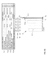
- FIG. 5 shows a display of the type which can be generated on a display panel by the disclosed method
- FIGS. 6 a to 6 c show exemplary embodiments for setting various times for the disclosed method.
- the vehicle switches into a second operating mode when the first operating mode ends.
- the range of the vehicle is determined when the first operating mode ends.
- the temporal development of a parameter from the surroundings of the vehicle is determined for a certain duration, wherein the vehicle is in the second operating mode for at least a portion of the certain duration.
- the temporal development of the range is predicted for the certain duration as a function of the range when the first operating mode ends and as a function of the temporal development of the parameter.
- the temporal development of the range is output.
- the vehicle is in a driving mode when in the first operating mode and is in a resting mode when in the second operating mode.
- the first operating mode is understood to be a mode in which the engine of the vehicle is switched on.
- the second operating mode is a mode in which the engine of the vehicle is switched off.
- a range prediction is output to the user also during a resting phase of the vehicle, in particular a stationary phase.
- the range of a vehicle is predicted only for the duration of the journey.
- a remaining range of the vehicle which can be achieved under the conditions present at the time of the end of the journey is output.
- the range of a vehicle is dependent upon different parameters. If these change during the stationary phase of the vehicle, the range of the vehicle also changes. If the user returns to the vehicle after a certain amount of time, he finds a different range than what was predicted at the previous end of the journey. It is therefore not possible to reliably plan for future journeys. Due to the prediction of the temporal development of the range as a function of a parameter from the surroundings of the vehicle, the user can better estimate the range he has available to him when he commences another journey and can therefore better plan his future journeys.
- a further time is determined, at which the switch from the second operating mode to the first operating mode is likely to take place, and the further time is output.
- the further time is the time when a new journey will commence.
- the user can, in particular, set the further time himself.
- the further time can be determined from a driving history of the vehicle. In this case, it is detected, for example, over a relatively long time period, at which times of day the user uses the vehicle and the further time is estimated on the basis thereof.
- the parameter comprises weather conditions in the surroundings of the vehicle.
- a weather forecast for the certain duration is determined.
- the weather forecast can be automatically obtained via a network and can be used for the forecast.
- Weather conditions are of particular interest in this case, because, in stationary phases, in particular, in which the vehicle is usually not switched on, weather conditions exert the greatest influence on the range prediction during the stationary phase.
- the external temperature in particular, has a great influence on the temporal development of the range.
- the energy, which must be expended for the air conditioning of the vehicle is dependent on the external temperature in particular.
- the energy quantity required to bring the internal temperature to a desired value is that much greater, the more the external temperature and the desired internal temperature deviate from one another.
- the position of the vehicle is determined and the weather forecast for the position of the vehicle is determined.
- the prediction of the range can be improved.
- the probability that weather fluctuations, which can also occur within a few kilometers, influence the prediction can therefore be reduced.
- the position of the vehicle can be determined in this case, in particular, via satellite navigation, such as, for example, GPS.
- a target energy quantity which the energy accumulator of the vehicle should have at the further time is determined.
- a target time is determined, at which a state of charge for charging the energy accumulator must be started to provide the target energy quantity at the further time.
- the target time is output.
- the user can determine himself which state of charge the energy accumulator should have when a new journey is commenced.
- a complete charging of a vehicle battery can be undesired, for reasons of cost.
- a target time is calculated, at which the state of charge must be started to permit the desired target energy quantity to be provided when a new journey is commenced.
- the temporal resolution of the certain duration is dependent upon the temporal resolution of the parameter.
- the temporal resolution of a weather forecast is usually limited and lasts for one to multiple hours or days. This means that each time within the temporal development of the parameter likewise has a certain duration.
- a graphic depiction can be generated on a display panel, by means of which the temporal development of the range is output.
- the graphic depiction comprises a diagram, optionally a bar graph, wherein the certain duration is plotted on a first axis and the predicted range is plotted on a second axis.
- the predicted range is output by means of a diagram, in particular by means of a length of the bars of the bar graph.
- the bar depiction results in an easily understood way to depict the range, in which the length of the bars is an easily understood display of the predicted range at any time during the predicted temporal development.
- the temporal resolution of the parameter has the unit “hours”.
- the certain duration comprises, for example, 24 hours and times of day having intervals of one hour between each of two consecutive times of day are plotted on the first axis.
- An hourly resolution is sufficient to enable a satisfactory resolution of the temporal development of the range to be provided.
- the graphic diagram can have a graphic element for each time which is output.
- the times which are output are, in particular, the further time and the target time.
- the first time is indirectly output via the first time of day on the first axis of the diagram. The user is, therefore, clearly shown, in the graphic representation, when a charging process starts and when a next commencement of driving is planned.
- a time at which a pre-air conditioning should be started can be determined.
- Pre-air conditioning is usually set for approximately 15 minutes before the commencement of driving. After 15 minutes of pre-air conditioning, the user usually finds himself in his desired climatic conditions in the vehicle.
- the pre-air conditioning can always be activated, for example, 15 minutes before the planned commencement of driving.
- the user can enter the time at which a pre-air conditioning should be started.
- a graphic element for the time of the pre-air conditioning can likewise be displayed on the display panel for this purpose.
- At least one of the graphic elements in the diagram can be moved along the first axis, so that the time can be set by moving the graphic element.
- the user can manually set the desired time in a simple and intuitive manner.
- the display panel on which the temporal development of the range is output is not disposed in the vehicle itself.
- the temporal development is output via a display panel of a cellular phone, tablet computers, PCs, or any other devices having display panels.
- the user does not need to return to the vehicle to change settings or to look at the temporal development of the range to set the times or output the temporal development of the range.
- Disclosed embodiments also relate to a device for predicting a range of a vehicle having an at least partially electric drive.
- the device comprises a detection unit, by means of which it is detected when a first operating mode of the vehicle is ended at a time, wherein the vehicle switches into a second operating mode when the first operating mode ends.
- the device comprises a determination unit, by means of which the range of the vehicle can be determined when the first operating mode ends and, starting at the time when the first operating mode ends, the temporal development of a parameter from the surroundings of the vehicle can be determined for a certain duration.
- the device comprises a prediction unit, by means of which the temporal development of the range for the certain duration can be predicted as a function of the range when the first operating mode ends and as a function of the temporal development of the parameter.
- the predicted temporal development of the range can be output by means of an output unit.
- the disclosed device is suited, in particular, for carrying out the disclosed method.
- Disclosed embodiments also relate to a vehicle comprising such a device.
- the vehicle is, in particular, a vehicle comprising a fully electric drive, for example, an electric vehicle, or a vehicle having a partially electric drive, i.e., for example, a hybrid vehicle.
- the total range of the vehicle is composed of the electric range, i.e., the range which can be achieved with the energy quantity available in the traction battery of the vehicle, and the conventional range, i.e., the range which can be achieved by means of the fuel quantity available in a conventional tank and which is available to an internal combustion engine.
- the vehicle is initially driven with electric energy from the traction battery.
- the electric range in particular, is of interest to the user. By means of the disclosed method, the electric range is therefore predicted and output to the user in the case of a hybrid vehicle, in particular.
- a first exemplary embodiment of the device 1 and an arrangement of the device 1 in a vehicle 7 are explained with reference to FIGS. 1 and 2 .
- the device 1 initially comprises a detection unit 8 , by means of which it is possible to detect when the vehicle 7 switches from a first operating mode into a second operating mode.
- the first operating mode in this case is a driving mode, in particular.
- the first operating mode is understood to be a mode in which the engine of the vehicle 7 is switched on.
- the second operating mode is, in particular, a resting mode of the vehicle 7 .
- the second operating mode is a mode in which the engine of the vehicle 7 is switched off.
- the detection unit 8 therefore detects when the engine of the vehicle 7 is switched off.
- the device 1 comprises a determination unit 4 .
- the determination unit 4 is configured, in this case, for determining different parameters. First, the determination unit 4 determines what the range of the vehicle 7 is when the driving mode ends. For this purpose, the determination unit 4 determines, in particular, the state of charge of an energy accumulator 5 , for example, a traction battery, at the time when the driving mode ends and calculates the range on the basis thereof.
- an energy accumulator 5 for example, a traction battery
- the determination unit 4 determines, for example, via a network 6 , the temporal development of the weather in the surroundings of the vehicle 7 .
- the weather is a parameter which influences the range prediction during a resting phase of the vehicle 7 .
- the parameters determined by the determination unit 4 are transmitted to a prediction unit 3 .
- the prediction unit 3 the temporal development of the range is then predicted on the basis of the corresponding parameters.
- the predicted temporal development of the range is transmitted to a control device 9 , which is disposed in a cellular phone 10 of the user.
- the control device 9 then generates, on the display panel 2 of the cellular phone 10 of the user, a graphic depiction for visualizing the temporal development of the range.
- the plurality of device components is disposed in the vehicle 7 itself.
- the determination unit 4 and the prediction unit 3 are disposed directly in or on the cellular phone 10 of the user.
- the cellular phone 10 is coupled to the network 6 from which the determination unit 4 obtains the weather forecast.
- the cellular phone 10 of the user has an application which has been developed especially for the range prediction.
- the traction battery 5 and the detection unit 8 are furthermore disposed in the vehicle 7 .
- the device 1 of the second exemplary embodiment comprises a further determination unit 11 which is coupled to the determination unit 4 , so that the determination unit 4 receives information, by means of the determination unit 11 , regarding the range and the state of charge of the traction battery 5 .
- a touch-sensitive surface in particular, can be disposed on the display panel 2 of the cellular phone 10 , by means of which the user can enter settings for the prediction of the temporal development of the range.
- the vehicle 7 can be either an electric vehicle or a hybrid vehicle. Both vehicle types comprise a traction battery 5 from which the energy for driving the vehicle 7 is supplied. In an electric vehicle, the drive energy is supplied only by the traction battery 5 . When the energy quantity in the traction battery 5 approaches the end, the traction battery 5 must be recharged. Continued operation of the vehicle 7 is not possible otherwise.
- the total range of a hybrid vehicle is composed of the electric range and a conventional range which can be achieved by the drive by means of a conventional fuel.
- the disclosed method is designed, in particular, for the electric range which can be achieved with the energy quantity available in the traction battery 5 .
- the user of a hybrid vehicle can better estimate how much further he can drive using a purely electric drive.
- the term “range” is intended to mean the electric range in particular.
- the starting point is that the driver switches off his vehicle 7 for parking, for example, overnight.
- step S 1 of the method it is initially detected that the vehicle 7 switches from a driving mode into a parking mode.
- step S 2 the range which can be achieved with the present state of charge under the present weather conditions is determined.
- step S 3 the determination unit 4 determines the position of the vehicle 7 . This is carried out, for example, via a navigation system having an integrated GPS receiver.
- step S 4 the determination unit 4 connects to the network 6 and obtains, via the network, a weather forecast for the next 24 hours at the position of the vehicle 7 .
- the weather forecast has a temporal resolution having the unit “hours”. This means that a separate weather forecast is provided for each of the 24 hours.
- the weather forecast for the 24 hours corresponds to a temporal development of the weather within the next 24 hours.
- step S 5 a prediction of the temporal development of the range within the next 24 hours is generated as a function of the temporal development of the weather forecast.
- step S 6 the predicted temporal development of the range is output on the display panel 2 of the cellular phone 10 of the user.
- the display which is displayed to the user on the display panel 2 of his cellular phone 10 is explained with reference to FIGS. 5 and 6 a to 6 c.
- a bar graph 12 having an x-axis and a y-axis is generated.
- the range R in kilometers is plotted on the y-axis and the determined duration t in hours is plotted on the x-axis.
- the x-axis is subdivided into times of day, in particular. In this case, there is a time span of one hour between two successively plotted times of day. The temporal resolution of the x-axis is therefore one hour.
- One bar 12 . 1 is plotted in the bar graph 12 for each x-axis point, i.e., for each time of day.
- Each bar 12 . 1 has a certain length L.
- the length L of each bar 12 . 1 corresponds to the range R predicted for the corresponding hour.
- An icon 14 for the weather forecast is also displayed above the bar graph 12 for each hour.
- the expected external temperature is displayed above the icons 14 .
- a value for the state of charge 16 is output between the bar graph 12 and the icons 14 .
- a table view 13 is displayed on the display panel 2 . Relevant parameters for the range prediction are displayed in the table view 13 . Information regarding the most recently completed journey is displayed in the top three columns 13 . 1 . In particular, the location of the vehicle 7 , a time t1 of the end of the journey, and the state of charge at the end of the journey are displayed. In this case, the time t1 is composed, in particular, of the time of day and the date.
- Information regarding the next commencement of a journey is indicated in columns 13 . 2 .
- the user can set a time t2 at which he is likely going to use the vehicle 7 again.
- a next commencement of a journey can be determined via a history of the vehicle use.
- a state of charge which the traction battery 5 should have at the commencement of the next journey can be indicated.
- Information regarding the state of charge is indicated in columns 13 . 3 .
- the user can either charge the vehicle 7 or not. If the user connects the vehicle 7 to a charging station, for example, a socket, he is shown, via the display, a target time t3, which represents the commencement of the actual charging process, and a target state of charge, which the traction battery 5 should have at the commencement of the next journey. If the user does not enter a target time t3 at which the charging process is intended to commence, this is determined in such a way that the value set for the target state of charge is achieved at the next commencement of a journey. The user can also set the target state of charge himself.
- a charging station for example, a socket
- the user is automatically displayed the type of charging used to charge the vehicle 7 , i.e., for example, via a common household socket or via a charging station.
- the maximum charging current is also determined and output. If the vehicle 7 is not charged during the idle mode, the user is not displayed a time of day or a date for the next commencement of charging. In this case, the information regarding the type of charging and the maximum current are likewise not displayed.
- Information regarding pre-air conditioning is provided in the last two columns. Provided certain conditions are met, the user can set, in principle, whether the pre-air conditioning should be activated during the resting phase of the vehicle 7 or not. If the pre-air conditioning is activated and, simultaneously, the vehicle 7 is charged, the energy required for the pre-air conditioning is drawn from the charging device. The energy required for this is therefore not subtracted from the energy quantity in the traction battery 5 . In addition, the user can set the length of time for pre-air conditioning to be carried out. A duration of 15 minutes is usually sufficient for heating or cooling a vehicle 7 to the internal temperature desired at the commencement of driving.
- Graphic elements 15 . 1 to 15 . 3 are displayed at certain times t2 to t4 in the bar graph 12 .
- the position of the graphic elements 15 . 1 to 15 . 3 in the bar graph 12 is dependent upon the times t2 to t4.
- the graphic elements 15 . 1 to 15 . 3 have the shape of a rod having a knob on the end. Every graphic element 15 . 1 to 15 . 3 can have a different color. Simultaneously, the columns in the table view 13 , which relate to a particular graphic element 15 . 1 to 15 . 3 , can be depicted in the same color. As a result, the assignment of the graphic elements 15 . 1 to 15 . 3 to a time is made easier for the user. If the graphic element 15 .
- the columns 13 . 3 of the table view 13 are displayed with a green background. If the graphic element 15 . 2 is depicted in blue, the associated columns 13 . 4 are likewise displayed with a blue background. If the graphic element 15 . 3 is depicted in yellow, the columns 13 . 2 are displayed with a yellow background. By means of this color pattern, the user is easily shown which graphic element 15 . 1 to 15 . 3 belongs to which time t2 to t4.
- the user wants to set the time t2 for example, he can do this directly in the table view 13 via the corresponding column, which corresponds to the upper column of the columns 13 . 2 .
- a window then opens, in which the user can set the desired time of day.
- the user can also move the graphic element 15 . 3 , which is assigned to the time t2, to the desired time of day directly via touch in the bar graph 12 . This is shown in FIG. 6 a . Since the time for a pre-air conditioning is then located after the time of the commencement of the journey, however, the graphic element 15 . 2 can be coupled to the movement of the graphic element 15 . 3 . The graphic element 15 . 2 is then moved to the same extent as the graphic element 15 . 3 . The distance D between the graphic elements 15 . 2 and 15 . 3 is retained.
- the distance D can be changed by moving the graphic element 15 . 2 .
- the duration for the pre-air conditioning can also be set via the lower column of the columns 13 . 4 . This is shown in FIG. 6 b.
- the setting of the target time t3 is shown in FIG. 6 c by way of example.
- either the graphic element 15 . 1 can be actively moved in the bar graph 12 by the user or, as an alternative, the time t3 can be set via the corresponding column in the table view 13 .
- the display in the table view 13 is automatically updated accordingly. If one of the times t2 to t4 is set via the display in the table view 13 , the position of the corresponding graphic element 15 . 1 to 15 . 3 is adapted to the entry accordingly.
- the temporal development is predicted anew.
- the temporal development of the weather can also be constantly checked. If there are changes in the weather forecast within the determined period t, the forecast of the temporal development of the range R must also be updated.
- the range forecast can be automatically generated. In the case of an automatic generation, default settings for the forecast are used. For example, the user can store preferred settings for the times t2 to t4 in the vehicle 7 . As an alternative, all settings can also be determined via a driving history.
- the range forecast can also be manually set by the user, however.
- the user sets all times t2 to t4, a target state of charge of the vehicle battery 5 , and a pre-air conditioning himself.
- the range prediction can also take place semi-automatically. In this case, many settings are taken from the table view 13 and many are manually set by the user. For example, a target state of charge can always be specified. In this case, the state of charge for the traction battery 5 deemed by the manufacturer to be optimal is stored in the table view 13 .
- a depiction of the total range i.e., the sum of the predicted electric range and the conventional range, can also be depicted, wherein a prediction for the conventional range is not generated.
- the user is then displayed not only a portion of the achievable range, but also the total achievable range of the vehicle 7 .
- the electric range is depicted so as to be visually separated from the conventional range, so that the user can nevertheless read the purely electric range from the combined display.
- a consumption display system for a vehicle is known from DE 10 2010 038 539 A1.
- This system comprises a display for depicting consumption information and means for ascertaining the present energy consumption of the vehicle.
- a central processing unit generates consumption information as a function of the ascertained energy consumption and displays this information in the display.
- a navigation system is connected to the central processing unit.
- the central processing unit stores a starting point and destination point pair ascertained by the navigation system as well as the particular distance covered and at least one consumption value ascertained between the starting point and the destination point. This consumption value is displayed in the display on demand.
- a vehicle is known from DE 10 2010 001 011 A1, in the case of which the electric power uptake of at least one auxiliary assembly of the motor vehicle can be reduced or completely shut off during purely electric driving depending on a driver's actuation of a control element, to increase the electric range of the motor vehicle during purely electric driving.
- the vehicle can further comprise a monitoring device for the state of charge of an electric energy accumulator. This monitoring device can reduce or completely shut off the power uptake of an auxiliary assembly on the basis of the electric power uptake. The increase in range achieved as a result is displayed to the driver.
- DE 10 2011 113 714 A1 makes known a method in which, on the basis of information related to the vehicle and the driving distance, an energy reserve available for propelling the vehicle is ascertained, a range based on the available energy reserve is determined via an allocation instruction, and a climate state is detected, wherein this is taken into account in the determination of the range.
- a method for determining the range of a motor vehicle is known from WO 2012/048766.
- climatic ambient conditions and the temperature or the physical/chemical state of at least one predetermined component of the motor vehicle is taken into account when determining the range of a motor vehicle.
- a range determination can be carried out even before the commencement of driving.
Landscapes
- Engineering & Computer Science (AREA)
- Transportation (AREA)
- Mechanical Engineering (AREA)
- Automation & Control Theory (AREA)
- Power Engineering (AREA)
- Radar, Positioning & Navigation (AREA)
- Remote Sensing (AREA)
- Life Sciences & Earth Sciences (AREA)
- Sustainable Energy (AREA)
- Sustainable Development (AREA)
- Human Computer Interaction (AREA)
- Physics & Mathematics (AREA)
- Combustion & Propulsion (AREA)
- Chemical & Material Sciences (AREA)
- General Physics & Mathematics (AREA)
- Mathematical Physics (AREA)
- Electric Propulsion And Braking For Vehicles (AREA)
Applications Claiming Priority (3)
| Application Number | Priority Date | Filing Date | Title |
|---|---|---|---|
| DE102014226031 | 2014-12-16 | ||
| DE102014226031.0 | 2014-12-16 | ||
| DE102014226031.0A DE102014226031A1 (de) | 2014-12-16 | 2014-12-16 | Verfahren und Vorrichtung zum Prognostizieren einer Reichweite eines Fahrzeugs mit zumindest teilweise elektrischem Antrieb |
Publications (2)
| Publication Number | Publication Date |
|---|---|
| US20160167643A1 US20160167643A1 (en) | 2016-06-16 |
| US10023176B2 true US10023176B2 (en) | 2018-07-17 |
Family
ID=54542041
Family Applications (1)
| Application Number | Title | Priority Date | Filing Date |
|---|---|---|---|
| US14/964,767 Active 2036-04-08 US10023176B2 (en) | 2014-12-16 | 2015-12-10 | Method and device for forecasting the range of a vehicle with an at least partially electric drive |
Country Status (4)
| Country | Link |
|---|---|
| US (1) | US10023176B2 (zh) |
| EP (1) | EP3034371B1 (zh) |
| CN (1) | CN105698806B (zh) |
| DE (1) | DE102014226031A1 (zh) |
Cited By (3)
| Publication number | Priority date | Publication date | Assignee | Title |
|---|---|---|---|---|
| US11145141B2 (en) | 2019-03-08 | 2021-10-12 | Ford Global Technologies, Llc | Electric vehicle predictive range estimating systems and methods |
| US11208062B2 (en) * | 2017-04-30 | 2021-12-28 | Cummins Inc. | Systems and methods for extending vehicle range to maximize operation distance |
| US20220097557A1 (en) * | 2019-11-21 | 2022-03-31 | Ecobrain Co., Ltd. | Information provision service system for electric vehicle using vehicle sensors |
Families Citing this family (14)
| Publication number | Priority date | Publication date | Assignee | Title |
|---|---|---|---|---|
| JP6168294B2 (ja) * | 2013-07-11 | 2017-07-26 | 三菱自動車エンジニアリング株式会社 | 走行可能距離算出装置 |
| JP6394558B2 (ja) * | 2015-10-16 | 2018-09-26 | トヨタ自動車株式会社 | 車両 |
| DE102015226229A1 (de) * | 2015-12-21 | 2017-06-22 | Bayerische Motoren Werke Aktiengesellschaft | Verfahren und Vorrichtung zur Reichweitenberechnung für ein Fahrzeug |
| US10137897B2 (en) * | 2016-06-13 | 2018-11-27 | Toyota Motor Engineering & Manufacturing North America, Inc. | Systems and methodologies for modifying a vehicle operating profile |
| JP6625505B2 (ja) * | 2016-09-29 | 2019-12-25 | 本田技研工業株式会社 | 車両の残走行距離の表示装置 |
| CN106994901B (zh) * | 2017-03-09 | 2023-03-21 | 上海蔚来汽车有限公司 | 车辆加电提醒方法和系统 |
| DE102017209133A1 (de) | 2017-05-31 | 2018-12-06 | Audi Ag | Verfahren zum Planen eines Ladevorganges zum Laden einer Energiespeichereinrichtung eines Kraftfahrzeugs, Ladeplanungseinrichtung, und Kraftfahrzeug |
| US10859391B2 (en) | 2018-11-27 | 2020-12-08 | Here Global B.V. | Method, apparatus, and computer program product for predicting range of an electric vehicle |
| DE102019204959A1 (de) * | 2019-04-08 | 2020-10-08 | Audi Ag | Energiemanagement für ein Elektrofahrzeug |
| US11190373B1 (en) | 2020-05-01 | 2021-11-30 | Samsara Inc. | Vehicle gateway device and interactive graphical user interfaces associated therewith |
| US11479142B1 (en) | 2020-05-01 | 2022-10-25 | Samsara Inc. | Estimated state of charge determination |
| CN113911120B (zh) * | 2020-07-08 | 2023-09-19 | 观致汽车有限公司 | 车辆续驶里程计算方法、装置、电子设备和存储介质 |
| CN111845446A (zh) * | 2020-07-22 | 2020-10-30 | 奇瑞商用车(安徽)有限公司 | 一种动力电池续航里程估算系统及方法 |
| DE102021120062A1 (de) | 2021-08-02 | 2023-02-02 | Bayerische Motoren Werke Aktiengesellschaft | Verfahren und Vorrichtung zur Ermittlung der Restreichweite eines Fahrzeugs |
Citations (15)
| Publication number | Priority date | Publication date | Assignee | Title |
|---|---|---|---|---|
| US5686895A (en) * | 1994-10-21 | 1997-11-11 | Honda Giken Kogyo Kabushiki Kaisha | Display unit for automobiles |
| US20030150655A1 (en) * | 2002-02-13 | 2003-08-14 | Nissan Motor Co., Ltd. | Fuel cell vehicle and method for predicting possible running distance |
| DE10302504A1 (de) * | 2003-01-23 | 2004-09-02 | Zf Friedrichshafen Ag | Verfahren zum Ermitteln der Reichweite eines Elektrofahrzeuges |
| US20100138142A1 (en) * | 2009-07-17 | 2010-06-03 | Karen Pease | Vehicle Range Finder |
| DE102010001011A1 (de) | 2010-01-19 | 2011-07-21 | Robert Bosch GmbH, 70469 | Verfahren zum Betrieb einer Kraft-Wärme-Kopplungsanlage |
| EP2385349A1 (en) | 2010-05-06 | 2011-11-09 | Leica Geosystems AG | Method and guidance unit for guiding battery-operated transportation means to reconditioning stations |
| US20110313610A1 (en) * | 2010-06-17 | 2011-12-22 | Gm Global Technology Operations, Inc. | Method and a system for providing a driving-range forecast for a vehicle |
| DE102010038539A1 (de) | 2010-07-28 | 2012-02-02 | Robert Bosch Gmbh | Verbrauchsanzeigesystem für ein Fahrzeug, Verfahren |
| WO2012048766A1 (de) | 2010-10-13 | 2012-04-19 | Audi Ag | Verfahren zum ermitteln der reichweite eines kraftfahrzeugs |
| US20120262104A1 (en) * | 2011-04-14 | 2012-10-18 | Honda Motor Co., Ltd. | Charge methods for vehicles |
| DE102011113714A1 (de) | 2011-09-17 | 2013-03-21 | Daimler Ag | Steuerungssystem und Verfahren zum Betreiben eines Kraftfahrzeugs mit zumindest zwei unterschiedlichen Antriebsmechanismen |
| US20130204456A1 (en) * | 2012-02-03 | 2013-08-08 | Mario Tippelhofer | Navigation system and method for an electric vehicle travelling from a starting point to a destination |
| US20140172282A1 (en) * | 2012-12-14 | 2014-06-19 | Industrial Technology Research Institute | Method and module for estimating after-charge drivable range of electric vehicle and driving assistance device |
| US20140214267A1 (en) * | 2013-01-25 | 2014-07-31 | Audi Ag | Predicting consumption and range of a vehicle based on collected route energy consumption data |
| US20160023562A1 (en) * | 2013-03-15 | 2016-01-28 | Schneider Electric USA, Inc. | Portable electric vehicle charging device |
-
2014
- 2014-12-16 DE DE102014226031.0A patent/DE102014226031A1/de not_active Withdrawn
-
2015
- 2015-11-12 EP EP15194206.7A patent/EP3034371B1/de active Active
- 2015-12-10 US US14/964,767 patent/US10023176B2/en active Active
- 2015-12-15 CN CN201510937288.XA patent/CN105698806B/zh active Active
Patent Citations (16)
| Publication number | Priority date | Publication date | Assignee | Title |
|---|---|---|---|---|
| US5686895A (en) * | 1994-10-21 | 1997-11-11 | Honda Giken Kogyo Kabushiki Kaisha | Display unit for automobiles |
| US20030150655A1 (en) * | 2002-02-13 | 2003-08-14 | Nissan Motor Co., Ltd. | Fuel cell vehicle and method for predicting possible running distance |
| DE10302504A1 (de) * | 2003-01-23 | 2004-09-02 | Zf Friedrichshafen Ag | Verfahren zum Ermitteln der Reichweite eines Elektrofahrzeuges |
| US20100138142A1 (en) * | 2009-07-17 | 2010-06-03 | Karen Pease | Vehicle Range Finder |
| DE102010001011A1 (de) | 2010-01-19 | 2011-07-21 | Robert Bosch GmbH, 70469 | Verfahren zum Betrieb einer Kraft-Wärme-Kopplungsanlage |
| EP2385349A1 (en) | 2010-05-06 | 2011-11-09 | Leica Geosystems AG | Method and guidance unit for guiding battery-operated transportation means to reconditioning stations |
| US20110313610A1 (en) * | 2010-06-17 | 2011-12-22 | Gm Global Technology Operations, Inc. | Method and a system for providing a driving-range forecast for a vehicle |
| DE102010038539A1 (de) | 2010-07-28 | 2012-02-02 | Robert Bosch Gmbh | Verbrauchsanzeigesystem für ein Fahrzeug, Verfahren |
| WO2012048766A1 (de) | 2010-10-13 | 2012-04-19 | Audi Ag | Verfahren zum ermitteln der reichweite eines kraftfahrzeugs |
| US20130218447A1 (en) * | 2010-10-13 | 2013-08-22 | Audi Ag | Method for determining the range of a motor vehicle |
| US20120262104A1 (en) * | 2011-04-14 | 2012-10-18 | Honda Motor Co., Ltd. | Charge methods for vehicles |
| DE102011113714A1 (de) | 2011-09-17 | 2013-03-21 | Daimler Ag | Steuerungssystem und Verfahren zum Betreiben eines Kraftfahrzeugs mit zumindest zwei unterschiedlichen Antriebsmechanismen |
| US20130204456A1 (en) * | 2012-02-03 | 2013-08-08 | Mario Tippelhofer | Navigation system and method for an electric vehicle travelling from a starting point to a destination |
| US20140172282A1 (en) * | 2012-12-14 | 2014-06-19 | Industrial Technology Research Institute | Method and module for estimating after-charge drivable range of electric vehicle and driving assistance device |
| US20140214267A1 (en) * | 2013-01-25 | 2014-07-31 | Audi Ag | Predicting consumption and range of a vehicle based on collected route energy consumption data |
| US20160023562A1 (en) * | 2013-03-15 | 2016-01-28 | Schneider Electric USA, Inc. | Portable electric vehicle charging device |
Non-Patent Citations (1)
| Title |
|---|
| Fakler; Machine translation of DE 10302504 A1; Sep. 2004; espacenet.com. * |
Cited By (4)
| Publication number | Priority date | Publication date | Assignee | Title |
|---|---|---|---|---|
| US11208062B2 (en) * | 2017-04-30 | 2021-12-28 | Cummins Inc. | Systems and methods for extending vehicle range to maximize operation distance |
| US11145141B2 (en) | 2019-03-08 | 2021-10-12 | Ford Global Technologies, Llc | Electric vehicle predictive range estimating systems and methods |
| US20220097557A1 (en) * | 2019-11-21 | 2022-03-31 | Ecobrain Co., Ltd. | Information provision service system for electric vehicle using vehicle sensors |
| US11858377B2 (en) * | 2019-11-21 | 2024-01-02 | Ecobrain Co., Ltd. | Information provision service system for electric vehicle using vehicle sensors |
Also Published As
| Publication number | Publication date |
|---|---|
| DE102014226031A1 (de) | 2016-06-16 |
| EP3034371A3 (de) | 2016-12-21 |
| EP3034371B1 (de) | 2021-04-14 |
| US20160167643A1 (en) | 2016-06-16 |
| CN105698806A (zh) | 2016-06-22 |
| EP3034371A2 (de) | 2016-06-22 |
| CN105698806B (zh) | 2019-05-07 |
Similar Documents
| Publication | Publication Date | Title |
|---|---|---|
| US10023176B2 (en) | Method and device for forecasting the range of a vehicle with an at least partially electric drive | |
| CN108202609B (zh) | 用于车辆电池管理的系统和方法及其车辆 | |
| EP2172740B1 (en) | Map display device, map display method, and computer readable tangible medium | |
| RU2489680C1 (ru) | Устройство и способ предоставления информации о станциях увеличения величины заряда батареи | |
| US9499065B2 (en) | Information display system and method | |
| CN106573546B (zh) | 为电动车辆呈现路线信息 | |
| US9121710B2 (en) | User interface system and method based on calendar event | |
| US20130345945A1 (en) | Method for implementing an energy management of a vehicle | |
| JP5771902B2 (ja) | 経路案内装置、経路案内方法及びコンピュータプログラム | |
| CN102589566B (zh) | 行程量表 | |
| US20170138750A1 (en) | Charging at Charging Stations for Range Extension | |
| WO2012014615A1 (ja) | 車両の電力消費量算出装置と情報提供装置及び情報提供方法 | |
| EP2752962A1 (en) | Charge/discharge assist device | |
| JP5974946B2 (ja) | 電源装置 | |
| JPWO2012098660A1 (ja) | ナビゲーション装置及び電動車両の充電制御装置 | |
| KR102243945B1 (ko) | 차량용 제어장치 및 자동차 | |
| US20160356616A1 (en) | Display of total vehicle trip range that is intuitive and minimizes range anxiety | |
| JP6531827B2 (ja) | 電動車両の充電支援方法及び充電支援装置 | |
| JP2013068590A (ja) | 電動車両 | |
| CN106061816B (zh) | 用于预测由于接通或切断车辆的车辆功能引起的行驶距离变化的方法和装置 | |
| JP2012194136A (ja) | 運転支援装置 | |
| CN106643753A (zh) | 电动汽车充电场站桩位导航系统及方法 | |
| US11945334B2 (en) | Method for determining a maximum value for a parameter range of a driving operation parameter of a motor vehicle and motor vehicle | |
| JP6183419B2 (ja) | 経路案内装置、経路案内方法及びコンピュータプログラム | |
| US20230015682A1 (en) | Electric vehicle trip planner |
Legal Events
| Date | Code | Title | Description |
|---|---|---|---|
| AS | Assignment |
Owner name: VOLKSWAGEN AG, GERMANY Free format text: ASSIGNMENT OF ASSIGNORS INTEREST;ASSIGNORS:TABANOGLU, GOEKHAN;VUJASINOVIC, MIRKO;REEL/FRAME:040275/0788 Effective date: 20151214 |
|
| STCF | Information on status: patent grant |
Free format text: PATENTED CASE |
|
| MAFP | Maintenance fee payment |
Free format text: PAYMENT OF MAINTENANCE FEE, 4TH YEAR, LARGE ENTITY (ORIGINAL EVENT CODE: M1551); ENTITY STATUS OF PATENT OWNER: LARGE ENTITY Year of fee payment: 4 |