US10003486B2 - Non-orthogonal multiple access (NOMA) wireless systems and methods - Google Patents
Non-orthogonal multiple access (NOMA) wireless systems and methods Download PDFInfo
- Publication number
- US10003486B2 US10003486B2 US14/632,291 US201514632291A US10003486B2 US 10003486 B2 US10003486 B2 US 10003486B2 US 201514632291 A US201514632291 A US 201514632291A US 10003486 B2 US10003486 B2 US 10003486B2
- Authority
- US
- United States
- Prior art keywords
- data signal
- noma
- transmission
- dci message
- processor
- Prior art date
- Legal status (The legal status is an assumption and is not a legal conclusion. Google has not performed a legal analysis and makes no representation as to the accuracy of the status listed.)
- Active, expires
Links
Images




Classifications
-
- H—ELECTRICITY
- H04—ELECTRIC COMMUNICATION TECHNIQUE
- H04L—TRANSMISSION OF DIGITAL INFORMATION, e.g. TELEGRAPHIC COMMUNICATION
- H04L5/00—Arrangements affording multiple use of the transmission path
- H04L5/003—Arrangements for allocating sub-channels of the transmission path
- H04L5/0044—Allocation of payload; Allocation of data channels, e.g. PDSCH or PUSCH
-
- H—ELECTRICITY
- H04—ELECTRIC COMMUNICATION TECHNIQUE
- H04L—TRANSMISSION OF DIGITAL INFORMATION, e.g. TELEGRAPHIC COMMUNICATION
- H04L27/00—Modulated-carrier systems
- H04L27/26—Systems using multi-frequency codes
- H04L27/2601—Multicarrier modulation systems
- H04L27/2626—Arrangements specific to the transmitter only
- H04L27/2627—Modulators
-
- H—ELECTRICITY
- H04—ELECTRIC COMMUNICATION TECHNIQUE
- H04J—MULTIPLEX COMMUNICATION
- H04J11/00—Orthogonal multiplex systems, e.g. using WALSH codes
- H04J11/0023—Interference mitigation or co-ordination
- H04J11/0026—Interference mitigation or co-ordination of multi-user interference
- H04J11/0036—Interference mitigation or co-ordination of multi-user interference at the receiver
- H04J11/004—Interference mitigation or co-ordination of multi-user interference at the receiver using regenerative subtractive interference cancellation
-
- H—ELECTRICITY
- H04—ELECTRIC COMMUNICATION TECHNIQUE
- H04L—TRANSMISSION OF DIGITAL INFORMATION, e.g. TELEGRAPHIC COMMUNICATION
- H04L1/00—Arrangements for detecting or preventing errors in the information received
- H04L1/0001—Systems modifying transmission characteristics according to link quality, e.g. power backoff
- H04L1/0002—Systems modifying transmission characteristics according to link quality, e.g. power backoff by adapting the transmission rate
- H04L1/0003—Systems modifying transmission characteristics according to link quality, e.g. power backoff by adapting the transmission rate by switching between different modulation schemes
-
- H—ELECTRICITY
- H04—ELECTRIC COMMUNICATION TECHNIQUE
- H04L—TRANSMISSION OF DIGITAL INFORMATION, e.g. TELEGRAPHIC COMMUNICATION
- H04L1/00—Arrangements for detecting or preventing errors in the information received
- H04L1/0001—Systems modifying transmission characteristics according to link quality, e.g. power backoff
- H04L1/0009—Systems modifying transmission characteristics according to link quality, e.g. power backoff by adapting the channel coding
-
- H—ELECTRICITY
- H04—ELECTRIC COMMUNICATION TECHNIQUE
- H04L—TRANSMISSION OF DIGITAL INFORMATION, e.g. TELEGRAPHIC COMMUNICATION
- H04L1/00—Arrangements for detecting or preventing errors in the information received
- H04L1/0001—Systems modifying transmission characteristics according to link quality, e.g. power backoff
- H04L1/0015—Systems modifying transmission characteristics according to link quality, e.g. power backoff characterised by the adaptation strategy
-
- H—ELECTRICITY
- H04—ELECTRIC COMMUNICATION TECHNIQUE
- H04L—TRANSMISSION OF DIGITAL INFORMATION, e.g. TELEGRAPHIC COMMUNICATION
- H04L1/00—Arrangements for detecting or preventing errors in the information received
- H04L1/0001—Systems modifying transmission characteristics according to link quality, e.g. power backoff
- H04L1/0023—Systems modifying transmission characteristics according to link quality, e.g. power backoff characterised by the signalling
- H04L1/0026—Transmission of channel quality indication
-
- H—ELECTRICITY
- H04—ELECTRIC COMMUNICATION TECHNIQUE
- H04L—TRANSMISSION OF DIGITAL INFORMATION, e.g. TELEGRAPHIC COMMUNICATION
- H04L25/00—Baseband systems
- H04L25/02—Details ; arrangements for supplying electrical power along data transmission lines
- H04L25/03—Shaping networks in transmitter or receiver, e.g. adaptive shaping networks
- H04L25/03891—Spatial equalizers
- H04L25/03898—Spatial equalizers codebook-based design
-
- H—ELECTRICITY
- H04—ELECTRIC COMMUNICATION TECHNIQUE
- H04L—TRANSMISSION OF DIGITAL INFORMATION, e.g. TELEGRAPHIC COMMUNICATION
- H04L27/00—Modulated-carrier systems
- H04L27/0012—Modulated-carrier systems arrangements for identifying the type of modulation
-
- H04L27/2608—
-
- H—ELECTRICITY
- H04—ELECTRIC COMMUNICATION TECHNIQUE
- H04L—TRANSMISSION OF DIGITAL INFORMATION, e.g. TELEGRAPHIC COMMUNICATION
- H04L27/00—Modulated-carrier systems
- H04L27/32—Carrier systems characterised by combinations of two or more of the types covered by groups H04L27/02, H04L27/10, H04L27/18 or H04L27/26
- H04L27/34—Amplitude- and phase-modulated carrier systems, e.g. quadrature-amplitude modulated carrier systems
- H04L27/3488—Multiresolution systems
-
- H—ELECTRICITY
- H04—ELECTRIC COMMUNICATION TECHNIQUE
- H04L—TRANSMISSION OF DIGITAL INFORMATION, e.g. TELEGRAPHIC COMMUNICATION
- H04L5/00—Arrangements affording multiple use of the transmission path
- H04L5/0001—Arrangements for dividing the transmission path
- H04L5/0028—Variable division
-
- H—ELECTRICITY
- H04—ELECTRIC COMMUNICATION TECHNIQUE
- H04L—TRANSMISSION OF DIGITAL INFORMATION, e.g. TELEGRAPHIC COMMUNICATION
- H04L5/00—Arrangements affording multiple use of the transmission path
- H04L5/003—Arrangements for allocating sub-channels of the transmission path
- H04L5/0044—Allocation of payload; Allocation of data channels, e.g. PDSCH or PUSCH
- H04L5/0046—Determination of the number of bits transmitted on different sub-channels
-
- H—ELECTRICITY
- H04—ELECTRIC COMMUNICATION TECHNIQUE
- H04L—TRANSMISSION OF DIGITAL INFORMATION, e.g. TELEGRAPHIC COMMUNICATION
- H04L5/00—Arrangements affording multiple use of the transmission path
- H04L5/0091—Signalling for the administration of the divided path, e.g. signalling of configuration information
- H04L5/0092—Indication of how the channel is divided
-
- H—ELECTRICITY
- H04—ELECTRIC COMMUNICATION TECHNIQUE
- H04W—WIRELESS COMMUNICATION NETWORKS
- H04W52/00—Power management, e.g. Transmission Power Control [TPC] or power classes
- H04W52/04—Transmission power control [TPC]
- H04W52/06—TPC algorithms
- H04W52/16—Deriving transmission power values from another channel
-
- H—ELECTRICITY
- H04—ELECTRIC COMMUNICATION TECHNIQUE
- H04W—WIRELESS COMMUNICATION NETWORKS
- H04W52/00—Power management, e.g. Transmission Power Control [TPC] or power classes
- H04W52/04—Transmission power control [TPC]
- H04W52/18—TPC being performed according to specific parameters
- H04W52/24—TPC being performed according to specific parameters using SIR [Signal to Interference Ratio] or other wireless path parameters
- H04W52/241—TPC being performed according to specific parameters using SIR [Signal to Interference Ratio] or other wireless path parameters taking into account channel quality metrics, e.g. SIR, SNR, CIR or Eb/lo
-
- H—ELECTRICITY
- H04—ELECTRIC COMMUNICATION TECHNIQUE
- H04W—WIRELESS COMMUNICATION NETWORKS
- H04W52/00—Power management, e.g. Transmission Power Control [TPC] or power classes
- H04W52/04—Transmission power control [TPC]
- H04W52/30—Transmission power control [TPC] using constraints in the total amount of available transmission power
- H04W52/34—TPC management, i.e. sharing limited amount of power among users or channels or data types, e.g. cell loading
- H04W52/346—TPC management, i.e. sharing limited amount of power among users or channels or data types, e.g. cell loading distributing total power among users or channels
-
- H—ELECTRICITY
- H04—ELECTRIC COMMUNICATION TECHNIQUE
- H04W—WIRELESS COMMUNICATION NETWORKS
- H04W52/00—Power management, e.g. Transmission Power Control [TPC] or power classes
- H04W52/04—Transmission power control [TPC]
- H04W52/38—TPC being performed in particular situations
- H04W52/42—TPC being performed in particular situations in systems with time, space, frequency or polarisation diversity
-
- H04W76/046—
-
- H—ELECTRICITY
- H04—ELECTRIC COMMUNICATION TECHNIQUE
- H04W—WIRELESS COMMUNICATION NETWORKS
- H04W76/00—Connection management
- H04W76/20—Manipulation of established connections
- H04W76/27—Transitions between radio resource control [RRC] states
-
- H—ELECTRICITY
- H04—ELECTRIC COMMUNICATION TECHNIQUE
- H04B—TRANSMISSION
- H04B7/00—Radio transmission systems, i.e. using radiation field
- H04B7/02—Diversity systems; Multi-antenna system, i.e. transmission or reception using multiple antennas
- H04B7/04—Diversity systems; Multi-antenna system, i.e. transmission or reception using multiple antennas using two or more spaced independent antennas
- H04B7/0413—MIMO systems
- H04B7/0417—Feedback systems
-
- H—ELECTRICITY
- H04—ELECTRIC COMMUNICATION TECHNIQUE
- H04L—TRANSMISSION OF DIGITAL INFORMATION, e.g. TELEGRAPHIC COMMUNICATION
- H04L27/00—Modulated-carrier systems
- H04L27/02—Amplitude-modulated carrier systems, e.g. using on-off keying; Single sideband or vestigial sideband modulation
-
- H—ELECTRICITY
- H04—ELECTRIC COMMUNICATION TECHNIQUE
- H04L—TRANSMISSION OF DIGITAL INFORMATION, e.g. TELEGRAPHIC COMMUNICATION
- H04L27/00—Modulated-carrier systems
- H04L27/18—Phase-modulated carrier systems, i.e. using phase-shift keying
-
- H—ELECTRICITY
- H04—ELECTRIC COMMUNICATION TECHNIQUE
- H04L—TRANSMISSION OF DIGITAL INFORMATION, e.g. TELEGRAPHIC COMMUNICATION
- H04L5/00—Arrangements affording multiple use of the transmission path
- H04L5/0001—Arrangements for dividing the transmission path
- H04L5/0014—Three-dimensional division
- H04L5/0023—Time-frequency-space
-
- H—ELECTRICITY
- H04—ELECTRIC COMMUNICATION TECHNIQUE
- H04L—TRANSMISSION OF DIGITAL INFORMATION, e.g. TELEGRAPHIC COMMUNICATION
- H04L5/00—Arrangements affording multiple use of the transmission path
- H04L5/003—Arrangements for allocating sub-channels of the transmission path
- H04L5/0053—Allocation of signalling, i.e. of overhead other than pilot signals
-
- H—ELECTRICITY
- H04—ELECTRIC COMMUNICATION TECHNIQUE
- H04W—WIRELESS COMMUNICATION NETWORKS
- H04W52/00—Power management, e.g. Transmission Power Control [TPC] or power classes
- H04W52/04—Transmission power control [TPC]
- H04W52/06—TPC algorithms
- H04W52/12—Outer and inner loops
Definitions
- the present disclosure relates to multiple access radio technology, and more specifically, to enabling non-orthogonal multiple access transmission by transmitting power multiplexed data signals (e.g., downlink) and control signals that facilitate decoding the power multiplexed data signals.
- power multiplexed data signals e.g., downlink
- control signals that facilitate decoding the power multiplexed data signals.
- RATs radio access technologies
- CDMA code division multiple access
- OFDMA orthogonal frequency division multiple access
- UEs user equipments
- TDMA time division multiple access
- mobile data traffic is expected to increase exponentially over the next decade, outstripping the ability of OMA technologies to meet mobile data traffic demands.
- FIG. 1 is a block diagram of a system that facilitates NOMA communication with a plurality of user equipments (UEs) according to various aspects described herein.
- UEs user equipments
- FIG. 2 is a block diagram of a system that facilitates NOMA communication with an Evolved NodeB (eNodeB or eNB) according to various aspects described herein.
- eNodeB Evolved NodeB
- FIG. 3 is a flow diagram of a method that facilitates NOMA communication with a plurality of UEs according to various aspects described herein.
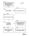
- FIG. 4 is a flow diagram of a method that facilitates NOMA communication with an eNodeB according to various aspects described herein.
- FIG. 5 is a graph of the power allocation ratio for UE 1 as a function of the SNR of UE 2 for UE 1 transmission ranks of 1 and 2 according to various aspects described herein.
- FIG. 6 is a table of example control signaling for a second user equipment (UE 2 ) with different types of MIMO receivers for various modulation orders according to various aspects described herein.
- UE 2 second user equipment
- FIG. 7A is a table indicating example numbers of bits for NOMA information for UE 1 according to various aspects described herein.
- FIG. 7B is a table indicating example content of the NOMA information field for UE 1 when the eNB is configured with 2 antenna ports according to various aspects described herein.
- FIG. 8 is a table indicating example signaling of precoding information content for four antenna ports according to various aspects described herein.
- FIG. 9 is a table indicating example signaling of precoding information content for two antenna ports according to various aspects described herein.
- FIG. 10A is a first portion of a table indicating example signaling of precoding information content for four antenna ports according to various aspects described herein.
- FIG. 10B is a second portion of a table indicating example signaling of precoding information content for four antenna ports according to various aspects described herein.
- FIG. 11 is a table of example signaling of the modulation order of code word 2 for UE 1 according to various aspects described herein.
- FIG. 12 is a table of example encoding of differential NOMA channel quality indicator information according to various aspects described herein.
- FIG. 13 is a block diagram illustrating an example user equipment useable in connection with various aspects described herein.
- a component can be a processor (e.g., a microprocessor, a controller, or other processing device), a process running on a processor, a controller, an object, an executable, a program, a storage device, a computer, a tablet PC and/or a user equipment (e.g., mobile phone, etc.) with a processing device.
- a processor e.g., a microprocessor, a controller, or other processing device
- a process running on a processor e.g., a microprocessor, a controller, or other processing device
- a process running on a processor e.g., a microprocessor, a controller, or other processing device
- an object e.g., an executable, a program
- storage device e.g., a computer, a tablet PC
- a user equipment e.g., mobile phone, etc.
- an application running on a server and the server can also be a component.
- One or more components can reside within a process, and a component can be localized on one computer and/or distributed between two or more computers.
- a set of elements or a set of other components can be described herein, in which the term “set” can be interpreted as “one or more.”
- these components can execute from various computer readable storage media having various data structures stored thereon such as with a module, for example.
- the components can communicate via local and/or remote processes such as in accordance with a signal having one or more data packets (e.g., data from one component interacting with another component in a local system, distributed system, and/or across a network, such as, the Internet, a local area network, a wide area network, or similar network with other systems via the signal).
- a signal having one or more data packets (e.g., data from one component interacting with another component in a local system, distributed system, and/or across a network, such as, the Internet, a local area network, a wide area network, or similar network with other systems via the signal).
- a component can be an apparatus with specific functionality provided by mechanical parts operated by electric or electronic circuitry, in which the electric or electronic circuitry can be operated by a software application or a firmware application executed by one or more processors.
- the one or more processors can be internal or external to the apparatus and can execute at least a part of the software or firmware application.
- a component can be an apparatus that provides specific functionality through electronic components without mechanical parts; the electronic components can include one or more processors therein to execute software and/or firmware that confer(s), at least in part, the functionality of the electronic components.
- NOMA non-orthogonal multiple access
- System 100 can include a memory 110 , a processor 120 , and a transmitter circuit 130 .
- system 100 can be included within an Evolved Universal Terrestrial Radio Access Network (E-UTRAN) Node B (Evolved Node B, eNodeB, or eNB).
- E-UTRAN Evolved Universal Terrestrial Radio Access Network
- Node B eNodeB
- eNB Evolved Node B
- Memory 110 can store data, executable instructions, and/or other information employed by system 100 .
- Processor 120 can (e.g., by executing executable instructions stored by memory 110 ) evaluate an orthogonal multiple access (OMA) metric and a NOMA metric of a plurality of UEs.
- OMA orthogonal multiple access
- NOMA NOMA
- the OMA metric and the NOMA metric can each be a measure of expected data throughput associated with the plurality of UEs in the respective modes (OMA transmission and NOMA transmission).
- both the OMA metric and the NOMA metric can be based on the proportional fairness metric, or some other metric that is a function of expected throughput.
- an individual OMA metric can be determined for each of the plurality of UEs assuming OMA transmission, and the OMA metric can be the best individual OMA metric (e.g., highest, etc.) of the individual OMA metrics.
- processor 120 can be configured to group the plurality of UEs into pairs and to determine a pairwise NOMA metric for each pair assuming NOMA transmission (e.g., with the pairwise NOMA metric as the sum of an individual NOMA metric for each UE in the pair), with the NOMA metric being the best pairwise NOMA metric (e.g., highest, etc.) of the pairwise NOMA metrics.
- UEs can be grouped into pairs in a variety of manners, such as by considering all possible pairings, or only a subset of pairings. As NOMA transmission is most effective when paired UEs have differing channel gain, UEs can be grouped into pairs based on differing channel gain between the UEs of a pair (e.g., as determined based on received signal-to-interference-plus-noise ratios (SINRs), etc.), and pairwise NOMA metrics can be determined only for those grouped pairs.
- SINRs received signal-to-interference-plus-noise ratios
- the UE with the higher channel gain (e.g., higher SINR, etc.) is referred to herein as the first UE (or UE 1 ), while the UE with the lower channel gain (e.g., lower SINR, etc.) is referred to herein as the second UE (or UE 2 ).
- UEs can be grouped into pairs on a continuous basis (e.g., for every sub-frame, etc.) or an intermittent basis (e.g., at various time intervals, based on changed conditions (e.g., received SINRs), etc.), which can be based on channel conditions (e.g., channel gains of the plurality of UEs as estimated via SINRs, etc.), which may change the designations of first UEs and second UEs as discussed herein (e.g., a first UE may become a second UE, or may be paired with a different second UE, etc.).
- a first UE may become a second UE, or may be paired with a different second UE, etc.
- processor 120 can generate a protocol instruction that indicates an OMA transmission or a NOMA transmission (e.g., which can occur for each sub-frame in various aspects; or less frequently, for example, wherein a previous one of OMA transmission or NOMA transmission is continued until indicated otherwise). For example, when the NOMA metric indicates superior throughput, a NOMA transmission can be indicated, and when the OMA metric indicates superior throughput, an OMA transmission can be indicated.
- the protocol instruction can indicate the OMA transmission or the NOMA transmission either explicitly (for example, by including an indicator such as one or more bits, symbols, etc. that designate the OMA transmission or NOMA transmission) or implicitly.
- an implicit indication may be indicated by including or omitting information such that, based on the inclusion or omission, the OMA transmission or the NOMA transmission can be determined based on the protocol instruction, e.g., by including (or, alternatively, omitting) additional information for the NOMA transmission, the NOMA transmission can be determined from the inclusion of the additional information (or, alternatively, the OMA transmission can be determined from the omission of the additional information), vice versa, etc.
- Processor 120 can also determine characteristics of the first and second UEs or first and second data signals, and alter or generate the first and/or second control signals based on the determined characteristics.
- the first and/or second control signals can indicate a power allocation ratio when the associated UE employs a multiple input multiple output (MIMO) receiver that requires channel amplitude information, or when a modulation and coding scheme (MCS) of the associated data signal has a higher modulation order than four (quadrature phase shift keying (QPSK)).
- MIMO multiple input multiple output
- MCS modulation and coding scheme
- QPSK quadrature phase shift keying
- the type of interference cancellation e.g., symbol level, codeword level
- the first UE can significantly affect the content of the first data signal, as explained in greater detail below.
- Transmitter circuit 130 is configured to couple to at least one antenna. Transmitter circuit 130 receives the protocol instruction that indicates the OMA transmission or the NOMA transmission, and transmits a first data signal and a first control signal associated with a first UE (UE 1 ), and a second data signal and a second control signal associated with a second UE (UE 2 ) in either OMA or NOMA, although, as discussed herein, the content and/or manner of transmission may vary between OMA and NOMA.
- the first data signal and the second data signal can be transmitted via a Physical Downlink Shared Channel (PDSCH), and the first control signal and the second control signal can be transmitted as Downlink Control Information (DCI) messages via a Physical Downlink Control Channel (PDCCH).
- PDSCH Physical Downlink Shared Channel
- DCI Downlink Control Information
- the transmitter circuit 130 can transmit data and control signals to one or more pairs of UEs with each pair of UEs comprising a first UE and a second UE, the operation is substantially similar for each pair, thus, for ease of illustration, only a single pair of UEs (the first UE and the second UE) is discussed.
- the first UE (UE 1 ) has a higher channel gain (e.g., as estimated via a higher reported SINR) than the second UE (UE 2 ).
- the unpaired UE can be regarded as a second UE, with a second data signal transmitted thereto without being power multiplexed with a first data signal, because in NOMA operation, as discussed in greater detail herein, the second UE treats the first data signal as noise in decoding the second data signal, thus the second UE will be able to decode the second data signal even in the absence of a first data signal.
- the transmitter circuit 130 can transmit the first data signal, first control signal, second data signal, and second control signal via conventional techniques via any OMA RAT, depending on the embodiment.
- the first control signal and the second control signal indicate the first and second data signals are transmitted via NOMA (either explicitly (e.g., by including an indicator (e.g., a bit, etc.) that specifies that the first and second data signals are transmitted via NOMA) or implicitly (e.g., by including or omitting information such that a receiving UE (e.g., UE 1 or UE 2 ) can determine from the inclusion or omission that the first and second data signals are transmitted via NOMA)).
- transmitter circuit 130 can employ, in connection with either an OMA transmission or a NOMA transmission, any of a number of different transmission modes that receiving UEs are configured for, such as transmit diversity, spatial multiplexing, etc.
- the first control signal and the second control signal can include sufficient information (e.g., via explicit or implicit indication) for the first UE and the second UE to decode, respectively, the first data signal and the second data signal, as discussed in greater detail herein.
- the processor 120 can determine a modulation and coding scheme (MCS) for the second data signal (e.g., based at least in part on one or more of the SINR of the second UE, characteristics of the second UE (e.g., of receiver(s) of the second UE), or other factors, such as those discussed herein (e.g., MCS restrictions, etc.)).
- MCS modulation and coding scheme
- the second control signal can indicate (e.g., explicitly or implicitly, as with all indicating discussed herein) the power scaling factor of the second data signal.
- the processor 120 can determine a receiver type of the second UE (e.g., maximum likelihood (ML) or minimum mean squared error (MMSE)).
- a receiver type of the second UE e.g., maximum likelihood (ML) or minimum mean squared error (MMSE)
- the second control signal can indicate the power scaling factor of the second data signal and a modulation order (or MCS) of the first data signal.
- the processor 120 can determine an interference cancellation (IC) level employed by the first UE (e.g., codeword level IC, symbol level IC, etc.). Depending on the determined IC level of the first UE, the first control signal can indicate different information, and characteristics of the first and second data signals can be employed to facilitate transmission.
- IC interference cancellation
- the first control signal can indicate a modulation order of the second data signal (e.g, as determined by processor 120 ).
- the first data signal and the second data signal can be scheduled to a common set of resources (e.g., a common set of physical resource blocks). Additionally, for codeword level IC, the processor 120 can determine a MCS of the second data signal, and the first control signal can indicate the MCS of the second data signal. Processor 120 can also determine an MCS of the first data signal, and, if the MCS of the first data signal includes amplitude modulation or amplitude-shift keying (e.g., a higher modulation order than four (quadrature phase shift keying (QPSK))), the first control signal can indicate the power scaling factor of the first data signal.
- amplitude modulation or amplitude-shift keying e.g., a higher modulation order than four (quadrature phase shift keying (QPSK)
- the processor 120 can determine the MCS of the second data signal and the first control signal can indicate the MCS of the second data signal.
- the processor 120 can determine an identifier of the second UE, and the first control signal can indicate the identifier of the second UE.
- the first control signal indicates the identifier of the second UE, this can be done in a variety of ways as discussed herein, such as via a pre-defined identifier of a plurality of pre-defined identifiers stored at the first UE (e.g., by indicating that, of n identifiers stored at the first UE, the second UE has the 2nd identifier, etc.).
- System 200 includes an antenna port 210 , a processor 220 , and an interference cancellation component 230 .
- system 200 can be included within a user equipment (UE), for example, with system 200 (or portions thereof) within a receiver circuit or transceiver circuit of a UE. Additional details of a UE according to one embodiment are provided in FIG. 13 and discussed in greater detail below.
- UE user equipment
- Antenna port 210 is configured to couple to at least one antenna, and antenna port 210 can receive a control signal and a data transmission that includes a first data signal and a second data signal. Although, in general, antenna port 210 will receive a plurality of control signals (e.g., a first control signal and a second control signal as discussed herein, as well as additional potential control signals), only one of those control signals (referred to as “the control signal”) contains control signaling for system 200 .
- a control signal e.g., a first control signal and a second control signal as discussed herein, as well as additional potential control signals
- Processor 220 can determine, based on the control signal, whether the data transmission is an OMA transmission or a NOMA transmission. If processor 220 determines the data transmission is a NOMA transmission, processor 220 further determines whether the control signal indicates a first reception protocol (e.g., wherein a UE comprising system 200 is a first UE) or a second reception protocol (e.g., wherein a UE comprising system 200 is a second UE). Additionally, when the data transmission is a NOMA transmission, the processor 220 decodes the second data signal, regardless of whether the control signal indicates the first or the second reception protocol.
- a first reception protocol e.g., wherein a UE comprising system 200 is a first UE
- a second reception protocol e.g., wherein a UE comprising system 200 is a second UE
- the processor 220 can designate the decoded second data signal as a received data signal associated with the system 200 .
- the interference cancellation component 230 need not be employed. Accordingly, in various aspects described herein, NOMA communications can be transmitted to a pair of UEs where only the first UE includes an interference cancellation component 230 , if possible given the channel conditions (e.g., the first UE has sufficient channel gain to decode the second data signal, subtract the second data signal, and decode the first data signal).
- the interference cancellation component 230 subtracts the decoded second data signal from the transmission to obtain the first data signal, and the processor 220 decodes the first data signal as the received data signal associated with system 200 .
- the control signal indicates (e.g., explicitly or implicitly) sufficient information for the system 200 to decode the second data signal and, under the first reception protocol, to decode the first data signal, as well.
- the control signal can indicate a power scaling factor of the second data signal.
- the control signal can indicate the modulation order or MCS of the second data signal under either the second reception protocol or the first reception protocol.
- interference cancellation component 230 can employ either codeword level interference cancellation or symbol level interference cancellation (IC).
- the control signal may indicate different information under the first reception protocol. For example, if codeword level IC is employed, the control signal can indicate a device identifier associated with the second data signal.
- processor 220 can attempt to decode the second data signal according to each of a plurality of device identifiers (e.g., 3 or 4 , etc.), and determine that the second data signal is decoded based on passing a cyclic redundancy check (CRC).
- CRC cyclic redundancy check
- system 200 may transmit different information.
- the processor 220 can determine a NOMA channel quality indicator (CQI) based on the NOMA transmission and subtraction of the decoded second data signal, and the antenna port 210 can transmit the NOMA CQI to the eNB.
- CQI NOMA channel quality indicator
- Method 300 can be implemented via an eNodeB, for example, a system such as that illustrated in FIG. 1 .
- Method 300 can include, at 310 , evaluating an OMA metric and a NOMA metric, wherein both the OMA metric and the NOMA metric are associated with a plurality of UEs.
- the metrics can be as described herein, such as performance metrics to determine potential data throughput in OMA communication and NOMA communication.
- method 300 can include generating a protocol instruction that indicates an OMA transmission or a NOMA transmission.
- method 300 includes transmitting, based on the protocol instruction, a first data signal and a first control signal associated with a first UE of the plurality of UEs, and a second data signal and a second control signal associated with a second UE of the plurality of UEs, where the second UE has a lower channel gain than the first UE.
- Act 330 can include acts 340 - 370 of method 300 , as the content and/or manner of transmission of the first and second data signals and first and second control signals can vary, depending on whether the first and second data signals are transmitted via OMA or NOMA.
- the transmitted signals can depend on whether the protocol instruction indicated an OMA transmission or a NOMA transmission. If the protocol instruction indicates a NOMA transmission, at 350 , the first data signal and the second data signal are power multiplexed via NOMA. At 360 , the first control signal and the second control signal indicate that the first data signal and the second data signal are transmitted via NOMA. Additionally, the first control signal and the second control signal include sufficient information to decode the NOMA transmission of the first data signal and the second data signal. If the protocol instruction indicates a NOMA transmission, information that can be indicated via the first control signal and/or the second control signal is discussed herein. For example, depending on the MCS or receiver type of the second UE, the second control signal can indicate a power scaling factor of the second data signal. The first control signal can indicate a power scaling factor of the first data signal and/or can indicate an MCS of the second data signal and/or an identifier of the second UE. Additional information that can be indicated and specific ways of indicating such information is discussed herein.
- the protocol instruction indicates an OMA transmission
- the first and second data signals are transmitted via OMA (according to any of a variety of RATs), and the OMA transmission can be indicated via the first control signal and the second control signal.
- method 400 can be implemented via a UE, for example, via a receiver circuit or transceiver circuit of a UE.
- Method 400 can include, at 410 , receiving a control signal and a data transmission that includes a first data signal and a second data signal.
- whether the data transmission is an OMA transmission or a NOMA transmission can be determined based on the control signal. If the data transmission is an OMA transmission, at 430 , a received data signal of the first data signal or the second data signal is decoded based on the control signal.
- the first and second data signals are power multiplexed, with the first data signal having a lower transmitted (and received) power. If the transmission is a NOMA transmission, at 440 , the second (higher power) data signal is decoded, regardless of whether the UE associated with or implementing method 400 is the first UE or the second UE. At 450 , a determination is made as to whether the control signal indicates a first reception protocol (for a first UE, having a higher channel gain) or a second reception protocol (for a second UE, having a lower channel gain).
- the UE implementing method 400 is the first UE, and the decoded second data signal is subtracted from the data transmission to obtain the first data signal, and at 470 , the first data signal is decoded as the received data signal. If the control signal indicates the second reception protocol, at 460 , the UE implementing method 400 is the second UE, and the decoded second data signal is designated as the received data signal.
- LTE-A Long Term Evolution-Advanced
- One example of a downlink NOMA system can be illustrated assuming that one eNB serves two UEs using the same frequency and time resource (for simplicity of illustration, only two UEs are considered; other UEs can be paired and simultaneously served in a similar manner).
- the eNB is mounted with N t transmit antennas (e.g., one or two in the example provided, although in various embodiments, more can be employed) and each UE is mounted with N r receive antennas.
- the modulated symbols of both UEs are summed up after power scaling before transmitting. This is described using equation (1):
- y i H i ⁇ ( p 1 ⁇ [ P 1 , P 2 ] / 2 ⁇ P ⁇ [ x 1 , 1 x 1 , 2 ] ⁇ x 1 + p 2 ⁇ P 1 ⁇ x 2 ⁇ x ) + n i ( 1 )
- y i is the N r ⁇ 1 received signal vector of user i
- H i is the N r ⁇ N t channel matrix of UE i
- p i is the transmit power scaling factor for user i
- [P 1 , P 2 ]/ ⁇ square root over (2) ⁇ is the precoder matrix for UE 1 and it is reduced to P 1 if UE 1 has rank one transmission
- P 1 is the precoder matrix for UE 2
- x i is the data symbol(s) of the codeword(s) intended for UE i
- x is the super-imposed data symbol(s) of both UEs
- n i is the N r
- MRC maximal ratio combining
- NOMA gain can be quantified via theoretical analysis.
- One possible way of obtaining p 1 * (i.e., the power level for UE 1 ) is to solve equation (5):
- Equation (5) When equation (5) is satisfied, the channel capacity of UE 2 equals that of OMA transmission in which UE 2 is allocated half of the system bandwidth and served with full transmit power. Therefore, the solution p 1 * to equation (5) simplifies the capacity comparison between NOMA and OMA. The channel capacity gain of NOMA over OMA is then dependent on the channel capacity of UE 1 . This can be written using equation (6):
- C NOMA - C OMA log 2 ⁇ ( 1 + p 1 * ⁇ ⁇ 1 ) - 1 2 ⁇ log 2 ⁇ ( 1 + ⁇ 1 ) , ( 6 )
- ⁇ 1 is the SNR of UE 1
- C NOMA is the channel capacity of NOMA
- C OMA is the channel capacity of OMA.
- FIG. 5 illustrates a graph of the power allocation ratio for UE 1 as a function of the SNR of UE 2 for UE 1 transmission ranks of 1 and 2 according to various aspects described herein.
- the channel capacity gain of NOMA over OMA is achieved if the power allocation ratio of UE 1 satisfies equation (8):
- dynamically switching between OMA and NOMA avoids the reduction of overall system capacity.
- the dynamic switching between OMA and NOMA can be based on performance metrics, such as by comparing data throughput assuming OMA with data throughput assuming NOMA is selected.
- metrics can be employed to compare metrics based on all UEs communicating with an eNB, in aspects, to reduce processing time, metrics can be based on only a subset of the UEs, such as the n (e.g., 1 , 2 , etc.) UEs with the best or worst performance in OMA or NOMA.
- Metrics employed can be a function of instantaneous channel condition or data rate and/or average throughput.
- both the OMA and NOMA metrics can be based on the proportional fairness (PF) metrics.
- PF proportional fairness
- the sum of PF metrics in a NOMA pair of UEs is used as the PF metric for the NOMA pair. If the PF metric of the best NOMA pair is higher than the PF metric of the best single UE transmission, NOMA transmission is employed. Otherwise, single UE (OMA) transmission is employed.
- PF proportional fairness
- Different interference cancellation components can be employed in receivers for NOMA decoding at a UE.
- the details of the signaling employed may be different, and the scheduling may also be affected.
- layer one signaling to describe the PDSCH attributes of the interferer signal can be reduced when transmitting PDSCH to UE 1 .
- additional signaling to UE 1 can be included to describe the PDSCH attributes of the interferer signal in aspects where UE 1 employs codeword level IC and is not scheduled to the same resources as UE 2 .
- the same modulation order and power ratio are used for two UEs when sending data signals to UEs via the Physical Downlink Shared Channel (PDSCH), but different UEs can be paired in different PRBs.
- PDSCH Physical Downlink Shared Channel
- the control signaling can include the power scaling factor p 2 if the modulation order is higher than that of QPSK, if UE 2 employs a MIMO receiver such as a minimum mean standard error (MMSE) type receiver. Additionally, the control signaling can include the power scaling factor p 2 for all modulations if UE 2 employs a MIMO receiver such as a MMSE-IRC (interference rejection combining) type receiver, which requires channel amplitude information.
- MMSE minimum mean standard error
- UE 2 can treat the super-imposed signal from UE 1 as additional interference, thus UE 2 's decoding can be assisted with minimal additional signaling.
- MIMO receivers minimum mean standard error (MMSE) and maximum likelihood (ML)
- QPSK quadrature phase shift keying
- QAM quadrature amplitude modulation
- the PDSCH to CRS energy per resource element (EPRE) ratio is configured by the UE specific radio resource control (RRC) parameter P A and the cell specific RRC parameter P B .
- RRC radio resource control
- PDSCH-ConfigDedicated:: SEQUENCE ⁇ p-a ENUMERATED ⁇ dB-6, dB-4dot77, dB-3, dB-1dot77, dB0, dB1, dB2, dB3 ⁇ ⁇
- p 2 indication Several options exist for p 2 indication.
- several enumerated p 2 values can be defined (e.g., in the RRC specification) and one of those values can be selected semi-statically. For example:
- DCI downlink control information
- p 2 can be defined and which value to use can be indicated in DCI.
- 2 bits can be introduced in the DCI to select one out of four values for p 2 including 0 dB. When 0 dB is indicated, it indicates OMA transmission.
- UE-specific reference symbol (UERS)-based transmission mode 7 , 8 , 9 , or 10 of the defined LTE transmission modes is configured for UE 2
- p 2 can also be indicated as in the above examples.
- the PDSCH to RS EPRE ratio is changed by adding p 2 (dB) to the existing PDSCH to RS EPRE ratio.
- UE 2 can assume that there exists one super-imposed PDSCH and its PDSCH to RS EPRE ratio is changed by adding
- UE 2 's transmission can have reduced flexibility, since UE 2 has relatively worse channel gain and the eNB cannot serve it with full transmission power.
- Example limitations that can be applied include reduced modulation and coding scheme (MCS), for example, only supporting QPSK and 16QAM; and/or only supporting rank one transmission.
- MCS modulation and coding scheme
- the reduced transmission flexibility may cause some redundancy in the DCI signaling, and that signaling can be either considered as a virtual cyclic redundancy check (CRC) state to increase the reliability of DCI or can be used to indicate partial modulation information of UE 1 .
- CRC virtual cyclic redundancy check
- UE 2 may only need four bits to indicate MCS 0 - 15 .
- the most significant bit can be used to indicate the MCS of UE 1 , e.g., whether it is 16QAM or 64QAM.
- the MCS/RV (redundancy version)/NDI (new data indicator) of the other transport block can be used to describe more detailed information of UE 1 's transmission MCS and rank if UE 2 's transmission-mode-dependent DCI is DCI 2 ⁇ , which supports two codeword indication.
- UE 1 For UE 1 , besides the power scaling factor p 1 which is needed when the modulation order of code word 1 is higher than that of QPSK, other signaling is also needed in order to describe code word 2 and the cell-radio network temporary identity (C-RNTI) of UE 2 .
- C-RNTI cell-radio network temporary identity
- NOMA can be applied to existing transmission schemes defined in the LTE specification, including spatial multiplexing and transmit diversity.
- the super-imposed signal can be sent using transmit diversity over a pair of two consecutive subcarriers.
- the super-imposed signal can be sent using one beam (one transmit precoding matrix indicator (PMI) in TM 4 , or one UERS port in TM 8 , 9 , or 10 ).
- PMI transmit precoding matrix indicator
- DCI format 1 is used to indicate single transport block transmission.
- DCI 2 ⁇ can indicate two transport block transmission.
- the MCS/NDI/RV for transport block (TB) 1 can be always for UE 1 's own TB, and the MCS/NDI/RV for transport block 2 can be always for UE 2 's TB.
- number of bits for precoding information in DCI 2 A is not needed, even if the UE is configured with TM 2 and the eNB is configured with 4 CRS ports.
- 1 bit of NOMA precoding information can be introduced to DCI 2 A if the eNB is configured with 2 CRS ports, as shown in FIG. 7A , showing a table indicating example numbers of bits for NOMA information for UE 1 according to various aspects described herein, and in FIG. 7B , showing a table indicating example content of the NOMA information field for UE 1 when the eNB is configured with 2 antenna ports according to various aspects described herein.
- the bit field pattern “3” in the precoding information field for 4 CRS ports can be reused to indicate NOMA transmission, as shown in FIG. 8 (showing example signaling of precoding information content for four antenna ports according to various aspects described herein), as a modification of 3GPP technical specification 36.213 vb20 at 5.3.3.1.5A-2, with additional or changed definitions indicated within the dashed area.
- some of the reserved bit field patterns in the precoding information field of DCI 2 can be used to describe the NOMA transmission if the eNB is configured with 2 antenna ports as shown in FIG. 9 (showing example signaling of precoding information content for two antenna ports according to various aspects described herein), as a modification of 3GPP technical specification 36.213 vb20 at 5.3.3.1.5-4, with additional or changed definitions indicated within the dashed area, where PMI is the precoding matrix indicator, and PUSCH is the physical uplink shared channel. If the eNB is configured with 4 antenna ports, similar definitions can be used, as shown in FIG. 10A and FIG.
- TM 4 with NOMA transmission can be extended to define TM 6 with NOMA transmission, since TM 6 is single layer closed loop MIMO (a special case of TM 4 ) and with NOMA transmission, DCI 1 B is not used for TM 4 and DCI 2 X is used for TM 6 with NOMA transmission.
- TM 6 is single layer closed loop MIMO (a special case of TM 4 ) and with NOMA transmission, DCI 1 B is not used for TM 4 and DCI 2 X is used for TM 6 with NOMA transmission.
- the behavior will be quite similar to that of TM 4 with NOMA transmission.
- aspects discussed herein can readily be extended to TM 5 (MU-MIMO) with NOMA.
- UE-specific RS is used for PDSCH demodulation.
- TMS 8 , 9 , and 10 are usually used to support beamforming with large number of antennas.
- the motivation to extend UE-specific RS based TMs with NOMA function is less than that of CRS based TMs.
- TM 8 , 9 , and 10 can be extended with NOMA functionalities by introducing a 1 bit NOMA function bit.
- NOMA function bit is “1” and both transport blocks are enabled, the number of transmission layers intended for one user equals to one; transport block 1 is mapped to codeword 0 ; and UE 2 's transport block is described using the MCS/NDI/RV of transport block 2 .
- Antenna port 7 is used for demodulation.
- the PDSCH to UE-specific RS EPRE ratio is p 1 for transport block 1 and 1 ⁇ p 1 for UE 2 's transport block.
- NOMA extension of TMs 8 , 9 , and 10 spatial multiplexing of up to 4 NOMA pairs can be supported, with each NOMA pair consisting of two NOMA users (e.g., a UE 1 and a UE 2 ).
- UE 1 uses code word level IC for NOMA decoding, UE 1 is sent signaling associated with UE 2 's C-RNTI in order to check whether the decoding of code word 2 is correct or not. Since NOMA pairing decisions need not be fixed and can be changed by the scheduler dynamically with time, including the full 16 bit C-RNTI of UE 2 in the DCI sent to UE 1 may not be ideal. Instead, one of several alternative approaches may be employed.
- RRC can be used to configure UE 1 with multiple potential C-RNTIs to pair with as UE 2 (e.g., 3 - 4 ), then UE 1 tests any of the possible C-RNTI for UE 2 when decoding code word 2 . If a CRC can pass after de-scrambling using any of the C-RNTI for UE 2 configured via RRC, then UE 1 can deduce that code word 2 is decoded successfully.
- RRC can be used to configure UE 1 with multiple potential C-RNTI to pair with as UE 2 (e.g., 3 - 4 ) and sufficient bits (e.g., 2 for 3 or 4 potential C-RNTI) can be added to the DCI to indicate which pairing C-RNTI is actually used as UE 2 's C-RNTI.
- UE 1 can then de-scramble using the indicated C-RNTI in the DCI to check whether a CRC of codeword 2 can pass.
- dedicated RRC signaling can be used to configure UE 1 with a set of potential NOMA pairing C-RNTIs (e.g., 16 , 32 , etc. C-RNTIs).
- the set size is large enough to avoid performance degradation due to required scheduling restriction and/or to avoid the need of frequent RRC signaling to update the set.
- New bits e.g., 4 or 5 bits, or whatever number is appropriate given the number of configured C-RNTIs
- a new RNTI called NOMA-RNTI is defined.
- NOMA-RNTI When NOMA is applied, the PDSCH of UE 2 is scrambled using the NOMA-RNTI so that UE 1 can know the scrambling codes of the PDSCH of UE 2 .
- NOMA When NOMA is not applied, the PDSCH of UE 2 is scrambled using the original C-RNTI of UE 2 .
- multiple new NOMA-RNTIs e.g., up to 4 , 8 , etc.
- the new NOMA-RNTIs are used to scramble the PDSCH of UE 2 .
- eNB chooses one of the new NOMA-RNTIs and explicitly signals it (in DCIs) to both of UE 1 and UE 2 .
- a cell-specific set of NOMA-RNTIs (e.g., 4 , 8 , etc.) is signaled as part of system information.
- neighbor cells can use different sets of NOMA-RNTIs. This can achieve inter-cell interference randomization with a small number of NOMA-RNTIs per cell.
- Both UE 1 and UE 2 are informed of which NOMA-RNTI from the set is used dynamically, via an appropriate number (e.g., 2 , 3 , etc.) of indication bits in the DCI.
- a UE 1 employing symbol level IC does not need to know the MCS/NDI/RV of code word 2 in order to cancel its contribution to the super-imposed received signal.
- the 8 bits MCS/NDI/RV of code word 2 can be reduced to 2 bits to describe the modulation of the super-imposed code word 2 as, shown in FIG. 11 , illustrating a table of example signaling of the modulation order of code word 2 for UE 1 according to various aspects described herein.
- Optimal power allocation and user pairing in NOMA can be provided if the eNB has knowledge of the effective channel power of each UE normalized by noise plus inter-cell interference power. This information can be implicitly delivered to the eNB by conventional channel quality indicator (CQI) calculation and feedback.
- CQI channel quality indicator
- the conventional CQI which does not take into account the NOMA co-channel interference, but is obtained through channel and inter-cell interference plus noise measurements, can be de-mapped to the effective SNR for each UE and be used for multi-user scheduling and power allocation.
- the signal-to-interference and noise ratio (SINR) of each UE can be considered for actual MCS selection.
- UE 2 receives interference from UE 1 .
- the impact of the interference from UE 1 to UE 2 on UE 2 's achievable throughput may not be significant, as the interference power is likely to be much smaller than the desired signal power via optimal power allocation.
- the interference from UE 2 to UE 1 is dependent on how good the interference can be cancelled by UE 1 .
- the CQI mismatch due to residual interference after interference cancellation may not be fully compensated by the eNB easily using techniques such as an outer loop link adaptation algorithm. Since outer loop usually takes time to converge, unless UE 1 compensates the interference from UE 2 in the reported CQI, the short term link adaptation outage cannot be avoided. This can be harmful for small packets when outer loop has not converged yet.
- UE 1 can additionally report CQI assuming NOMA transmission and interference cancellation. With the given hypothetical modulation order of UE 2 and power allocation ratio, the residual interference can be estimated, and CQI can calculated based on effective SINR after interference cancellation.
- aspects described herein can provide for modifications of current wireless technologies and/or standards to incorporate NOMA transmission.
- LTE-A specifications and standards can be modified to incorporate aspects described herein.
- NOMA CQI the CQI definition can be changed such that it reads as below, as an example modification of the 3GPP technical specification 36.213 vb30 at section 7.2.3, through table 7.2.3-1:
- x ( ⁇ -1) (i)] T is a vector of symbols from the layer mapping in section 6.3.3.2 of [3]
- P ⁇ 1,2,4,8 ⁇ is the number of CSI-RS ports configured, and if only one CSI-RS port is configured, W(i) is 1, otherwise W(i) is the precoding matrix corresponding to the reported PMI applicable to x(i).
- the corresponding PDSCH signals transmitted on antenna ports ⁇ 15 . . . 14+P ⁇ would have a ratio of EPRE to CSI-RS EPRE equal to the ratio given in section 7.2.5.
- a UE may not need to report the NOMA CQI for all subbands.
- One way to report in a bandwidth-efficient manner is simply to report a delta CQI for the whole system bandwidth.
- the delta CQI can be encoded using 2 bits instead of 4 bits, such as shown in the example table of FIG. 12 , illustrating a table of example encoding of differential NOMA channel quality indicator information according to various aspects described herein.
- the user equipment 1300 comprises a digital baseband processor 1302 that can be coupled to a data store or memory 1303 , a front end 1304 (e.g., an RF front end, an acoustic front end, or the other like front end) and a plurality of antenna ports 1307 for connecting to a plurality of antennas 1306 1 to 1306 k (k being a positive integer).
- a digital baseband processor 1302 that can be coupled to a data store or memory 1303
- a front end 1304 e.g., an RF front end, an acoustic front end, or the other like front end
- a plurality of antenna ports 1307 for connecting to a plurality of antennas 1306 1 to 1306 k (k being a positive integer).
- the antennas 1306 1 to 1306 k can receive and transmit signals to and from one or more wireless devices such as access points, access terminals, wireless ports, routers and so forth, which can operate within a radio access network or other communication network generated via a network device.
- the user equipment 1300 can be a radio frequency (RF) device for communicating RF signals, an acoustic device for communicating acoustic signals, or any other signal communication device, such as a computer, a personal digital assistant, a mobile phone or smart phone, a tablet PC, a modem, a notebook, a router, a switch, a repeater, a PC, network device, base station or a like device that can operate to communicate with a network or other device according to one or more different communication protocols or standards.
- RF radio frequency
- the front end 1304 can include a communication platform, which comprises electronic components and associated circuitry that provide for processing, manipulation or shaping of the received or transmitted signals via one or more receivers or transmitters 1308 , with at least one receiver comprising an interference cancellation component 1309 , a mux/demux component 1312 , and a mod/demod component 1314 .
- the front end 1304 is coupled to the digital baseband processor 1302 and the set of antenna ports 1307 , in which the set of antennas 1306 1 to 1306 k can be part of the front end.
- At least one receiver 1308 can comprise an interference cancellation (IC) component 1309 and be configured to receive and decode non-orthogonal multiple access (NOMA) communications.
- IC interference cancellation
- NOMA non-orthogonal multiple access
- user equipment 1300 can receive a control signal that indicates whether it is a first user equipment (UE 1 ) with a higher channel gain (in which case its data signal will have a lower received power than that of the paired user equipment), or a second user equipment (UE 2 ) with a lower channel gain (in which case its data signal will have a higher received power than that of the paired user equipment). In both cases, receiver 1308 can decode the data signal with the higher received power.
- UE 1 first user equipment
- UE 2 second user equipment
- receiver 1308 can decode the data signal with the higher received power.
- receiver 1308 In response to the control signal indicating that the user equipment 1300 is the second user equipment, receiver 1308 can determine the decoded higher power data signal to be a received data signal for user equipment 1300 . In response to the control signal indicating that the user equipment 1300 is the second user equipment, interference cancellation component 1309 can reconstruct the higher power data signal and subtract it from the total received data signal to obtain the lower power data signal. Receiver 1308 can decode the lower power data signal and determine the decoded lower power data signal to be the received data signal for user equipment 1300 .
- the user equipment 1300 can also include a processor 1302 or a controller that can operate to provide or control one or more components of the user equipment 1300 .
- the processor 1302 can confer functionality, at least in part, to substantially any electronic component within the user equipment 1300 , in accordance with aspects of the disclosure.
- the processor can be configured to execute, at least in part, executable instructions that control determination of whether a communication is a NOMA communication, and decoding and interference cancellation of NOMA communications via receiver 1308 and interference cancellation component 1309 .
- the processor 1302 can operate to enable the user equipment 1300 to process data (e.g., symbols, bits, or chips) for multiplexing/demultiplexing with the mux/demux component 1312 , or modulation/demodulation via the mod/demod component 1314 , such as implementing direct and inverse fast Fourier transforms, selection of modulation rates, selection of data packet formats, inter-packet times, etc.
- data e.g., symbols, bits, or chips
- Memory 1303 can store data structures (e.g., metadata), code structure(s) (e.g., modules, objects, classes, procedures, or the like) or instructions, network or device information such as policies and specifications, attachment protocols, code sequences for scrambling, spreading and pilot (e.g., reference signal(s)) transmission, frequency offsets, cell IDs, and other data for detecting and identifying various characteristics related to RF input signals, a power output or other signal components during power generation.
- data structures e.g., metadata
- code structure(s) e.g., modules, objects, classes, procedures, or the like
- instructions e.g., modules, objects, classes, procedures, or the like
- network or device information such as policies and specifications, attachment protocols, code sequences for scrambling, spreading and pilot (e.g., reference signal(s)) transmission, frequency offsets, cell IDs, and other data for detecting and identifying various characteristics related to RF input signals, a power output or other signal components during power generation.
- the processor 1302 is functionally and/or communicatively coupled (e.g., through a memory bus) to memory 1303 in order to store or retrieve information necessary to operate and confer functionality, at least in part, to communication platform or front end 1304 including the receiver 1308 and interference cancellation component 1309 , and the PA system 910 . While the components in FIG. 13 are illustrated in the context of a user equipment, such illustration is not limited to user equipment but also extends to other wireless communication devices, such as base station (e.g., eNodeB), small cell, femtocell, macro cell, microcell, etc.
- base station e.g., eNodeB
- Examples herein can include subject matter such as a method, means for performing acts or blocks of the method, at least one machine-readable medium including executable instructions that, when performed by a machine (e.g., a processor with memory or the like) cause the machine to perform acts of the method or of an apparatus or system for concurrent communication using multiple communication technologies according to embodiments and examples described.
- a machine e.g., a processor with memory or the like
- Example 1 is an Evolved NodeB (eNB), comprising a memory, a processor, and a transmitter circuit.
- the memory stores executable instructions.
- the processor is configured to execute the executable instructions to at least: evaluate an orthogonal multiple access (OMA) metric and a non-orthogonal multiple access (NOMA) metric of a plurality of user equipments (UEs) comprising a first UE and a second UE having a lower channel gain than the first UE; generate, based on the OMA metric and the NOMA metric, a protocol instruction that indicates an OMA transmission or a NOMA transmission; and determine a first modulation and coding scheme (MCS) for the first UE and a second MCS for the second UE.
- OMA orthogonal multiple access
- NOMA non-orthogonal multiple access
- the transmitter circuit is configured to receive the protocol instruction and to transmit, in response thereto, a first data signal and a first downlink control information (DCI) message associated with the first UE, and a second data signal and a second DCI message associated with the second UE.
- DCI downlink control information
- the first data signal and the second data signal are power multiplexed
- the first DCI message and the second DCI message indicate the first data signal and the second data signal are transmitted via NOMA
- the first DCI message indicates the second MCS.
- Example 2 includes the subject matter of example 1, wherein the transmitter circuit is configured to transmit to the plurality of UEs, wherein the processor is further configured to execute the executable instructions to determine an individual OMA metric for each of the plurality of UEs and a pairwise NOMA metric for each of one or more pairs of UEs of the plurality of UEs, wherein the OMA metric is a best individual OMA metric of the individual OMA metrics, and wherein the NOMA metric is a best pairwise NOMA metric of the pairwise NOMA metrics.
- Example 3 includes the subject matter of any of examples 1-2, including or omitting optional features, wherein, in response to a determination that the second MCS includes amplitude-shift keying or amplitude modulation, a power scaling factor of the second data signal is indicated via at least one of the second DCI message or a radio resource control (RRC) signal that the transmitter circuit is configured to transmit.
- RRC radio resource control
- Example 4 includes the subject matter of any of examples 1-3, including or omitting optional features, wherein the processor is further configured to execute the executable instructions to determine a receiver type of the second UE, wherein, in response to a determination that the receiver type of the second UE is configured to employ channel amplitude information, the second DCI message indicates a modulation order of the first data signal, and a power scaling factor of the second data signal is indicated via at least one of the second DCI message or a radio resource control (RRC) signal that the transmitter circuit is configured to transmit.
- RRC radio resource control
- Example 5 includes the subject matter of any of examples 1-4, including or omitting optional features, wherein the processor is further configured to execute the executable instructions to determine an interference cancellation level of the first UE.
- Example 6 includes the subject matter of any of examples 5, including or omitting optional features, wherein, in response to a determination that the interference cancellation level is symbol level, the first data signal and the second data signal are scheduled to a distinct set of physical resource blocks (PRBs).
- PRBs physical resource blocks
- Example 7 includes the subject matter of any of examples 5, including or omitting optional features, wherein, in response to a determination that the interference cancellation level is codeword level, the first data signal and the second data signal are scheduled to a common set of physical resource blocks (PRBs).
- PRBs physical resource blocks
- Example 8 includes the subject matter of any of examples 1-7, including or omitting optional features, wherein the first DCI message indicates a power scaling factor of the first data signal in response to a determination that the MCS of the first data signal includes amplitude-shift keying or amplitude modulation.
- Example 9 includes the subject matter of example 1, wherein, in response to a determination that the second MCS includes amplitude-shift keying or amplitude modulation, a power scaling factor of the second data signal is indicated via at least one of the second DCI message or a radio resource control (RRC) signal that the transmitter circuit is configured to transmit.
- RRC radio resource control
- Example 10 includes the subject matter of example 1, wherein the processor is further configured to execute the executable instructions to determine a receiver type of the second UE, wherein, in response to a determination that the receiver type of the second UE is configured to employ channel amplitude information, the second DCI message indicates a modulation order of the first data signal, and a power scaling factor of the second data signal is indicated via at least one of the second DCI message or a radio resource control (RRC) signal that the transmitter circuit is configured to transmit.
- RRC radio resource control
- Example 11 includes the subject matter of example 1, wherein the processor is further configured to execute the executable instructions to determine an interference cancellation level of the first UE.
- Example 12 includes the subject matter of example 11, wherein, in response to a determination that the interference cancellation level is symbol level, the first data signal and the second data signal are scheduled to a distinct set of physical resource blocks (PRBs).
- PRBs physical resource blocks
- Example 13 includes the subject matter of example 11, wherein, in response to a determination that the interference cancellation level is codeword level, the first data signal and the second data signal are scheduled to a common set of physical resource blocks (PRBs).
- PRBs physical resource blocks
- Example 14 includes the subject matter of example 1, wherein the first DCI message indicates a power scaling factor of the first data signal in response to a determination that the MCS of the first data signal includes amplitude-shift keying or amplitude modulation.
- Example 15 is a user equipment (UE), comprising an antenna port, a processor, and an interference cancellation component.
- the antenna port is configured to couple to at least one antenna, wherein the antenna port is configured to receive a physical downlink control channel (PDCCH) transmission comprising a downlink control information (DCI) message and to receive a physical downlink shared channel (PDSCH) transmission comprising a first data signal and a second data signal.
- PDCCH physical downlink control channel
- DCI downlink control information
- PDSCH physical downlink shared channel
- the processor is operably coupled to the antenna port and configured to decode the second data signal to obtain a decoded second data signal and to determine, based on the DCI message, whether the PDSCH transmission is an orthogonal multiple access (OMA) transmission or a non-orthogonal multiple access NOMA transmission, wherein, in response to a determination that the PDSCH transmission is the NOMA transmission, the processor is configured to determine whether the DCI message indicates a first reception protocol or a second reception protocol distinct from the first reception protocol.
- the interference cancellation component is operably coupled to the antenna port and configured to employ interference cancellation according to at least one of a codeword level or a symbol level.
- the interference cancellation component is configured to employ the interference cancellation to subtract the decoded second data signal from the PDSCH transmission to obtain the first data signal, and the processor is configured to decode the first data signal as a received data signal.
- the processor is configured to designate the decoded second data signal as the received data signal.
- Example 16 includes the subject matter of example 15, wherein the DCI message indicates a power scaling factor of the second data signal, and wherein the processor is configured to decode the second data signal based at least in part on the power scaling factor of the second data signal.
- Example 17 includes the subject matter of any of examples 15-16, including or omitting optional features, wherein, in response to the determination that the DCI message indicates the first reception protocol, the processor is configured to determine, based on the DCI message, a modulation order of the second data signal.
- Example 18 includes the subject matter of any of examples 15-17, including or omitting optional features, wherein the interference cancellation component is configured to employ interference cancellation according to the symbol level, and wherein the DCI message indicates a first modulation and coding scheme (MCS) of the first data signal and a second MCS of the second data signal.
- MCS modulation and coding scheme
- Example 19 includes the subject matter of any of examples 15-17, including or omitting optional features, wherein the interference cancellation component is configured to employ interference cancellation according to the codeword level, and in response to the determination that the DCI message indicates the first reception protocol, the processor is configured to determine a radio network temporary identity (RNTI) associated with the second data signal, wherein the processor is configured to decode the second data signal based at least in part on the RNTI associated with the second data signal.
- RNTI radio network temporary identity
- Example 20 includes the subject matter of any of examples 19, including or omitting optional features, wherein the antenna port is further configured to receive a radio resource control (RRC) signal comprising a plurality of cell-RNTIs (C-RNTIs), wherein the processor is configured to determine the RNTI associated with the second data signal from among the plurality of C-RNTIs.
- RRC radio resource control
- Example 21 includes the subject matter of any of examples 20, including or omitting optional features, wherein the processor is configured to attempt to decode the second data signal according to one or more of the plurality of C-RNTIs in order to determine the RNTI associated with the second data signal.
- Example 22 includes the subject matter of any of examples 20, including or omitting optional features, wherein the processor is configured to determine, based on the DCI message, the RNTI associated with the second data signal from among the plurality of C-RNTIs.
- Example 23 includes the subject matter of any of examples 19, including or omitting optional features, wherein the processor is configured to determine, based on the DCI message, the RNTI associated with the second data signal from among a plurality of NOMA-specific RNTIs.
- Example 24 includes the subject matter of any of examples 15-23, including or omitting optional features, wherein, in response to the determination that the DCI message indicates the first reception protocol, the processor is configured to determine a NOMA channel quality indicator (CQI) based on the NOMA transmission and subtraction of the decoded second data signal, wherein the antenna port is configured to transmit the NOMA CQI
- CQI NOMA channel quality indicator
- Example 25 includes the subject matter of example 15, wherein, in response to the determination that the DCI message indicates the first reception protocol, the processor is configured to determine, based on the DCI message, a modulation order of the second data signal.
- Example 26 includes the subject matter of example 15, wherein the interference cancellation component is configured to employ interference cancellation according to the symbol level, and wherein the DCI message indicates a first modulation and coding scheme (MCS) of the first data signal and a second MCS of the second data signal.
- MCS modulation and coding scheme
- Example 27 includes the subject matter of example 15, wherein the interference cancellation component is configured to employ interference cancellation according to the codeword level, and in response to the determination that the DCI message indicates the first reception protocol, the processor is configured to determine a radio network temporary identity (RNTI) associated with the second data signal, wherein the processor is configured to decode the second data signal based at least in part on the RNTI associated with the second data signal.
- RNTI radio network temporary identity
- Example 28 includes the subject matter of example 27, wherein the antenna port is further configured to receive a radio resource control (RRC) signal comprising a plurality of cell-RNTIs (C-RNTIs), wherein the processor is configured to determine the RNTI associated with the second data signal from among the plurality of C-RNTIs.
- RRC radio resource control
- Example 29 includes the subject matter of example 28, wherein the processor is configured to attempt to decode the second data signal according to one or more of the plurality of C-RNTIs in order to determine the RNTI associated with the second data signal.
- Example 30 includes the subject matter of example 28, wherein the processor is configured to determine, based on the DCI message, the RNTI associated with the second data signal from among the plurality of C-RNTIs.
- Example 31 includes the subject matter of example 27, wherein the processor is configured to determine, based on the DCI message, the RNTI associated with the second data signal from among a plurality of NOMA-specific RNTIs.
- Example 32 includes the subject matter of example 15, wherein, in response to the determination that the DCI message indicates the first reception protocol, the processor is configured to determine a NOMA channel quality indicator (CQI) based on the NOMA transmission and subtraction of the decoded second data signal, wherein the antenna port is configured to transmit the NOMA CQI.
- CQI NOMA channel quality indicator
- Example 33 is a non-transitory machine readable medium comprising instructions that, when executed, cause an Evolved NodeB (eNB) to: determine a projected first data throughput of an orthogonal multiple access (OMA) protocol and a projected second data throughput of a non-orthogonal multiple access (NOMA) protocol; select, based on a comparison between the projected first data throughput and the projected second data throughput, the OMA protocol or the NOMA protocol as a selected protocol; determine, in response to selecting the NOMA protocol, a first power allocation ratio for a first UE and a second power allocation ratio for a second UE with a lower signal-to-interference-plus-noise ratio (SINR) than the first UE, wherein the second power allocation ratio is greater than the first power allocation ratio; transmit, via a physical downlink shared channel (PDSCH), a first data signal associated with the first UE according to a first transmission mode and a second data signal associated with the second UE according to a second transmission mode, wherein
- Example 34 includes the subject matter of example 33, wherein the first DCI message indicates a modulation and coding scheme (MCS) of the second data signal.
- MCS modulation and coding scheme
- Example 35 includes the subject matter of any of examples 33-34, including or omitting optional features, wherein the second DCI message indicates a modulation and coding scheme (MCS) of the first data signal.
- MCS modulation and coding scheme
- Example 36 includes the subject matter of example 33, wherein the second DCI message indicates a modulation and coding scheme (MCS) of the first data signal.
- MCS modulation and coding scheme
- Example 37 includes the subject matter of example 33, wherein, in response to the first transmission mode comprising transmit diversity, the super-imposed signal is transmitted via transmit diversity over a pair of consecutive sub-carriers.
- Example 38 includes the subject matter of example 33, wherein, in response to the first transmission mode comprising spatial multiplexing, the super-imposed signal is transmitted via a single beam.
- Example 39 includes the subject matter of example 33, wherein the first DCI message indicates the first power allocation ratio.
- Example 40 includes the subject matter of example 33, wherein the second DCI message indicates the second power allocation ratio.
- Example 41 is a system that facilitates non-orthogonal multiple access (NOMA) communication, comprising a memory, a processor, and a transmitter circuit.
- the memory stores executable instructions.
- the processor is configured to execute the executable instructions to at least: evaluate an orthogonal multiple access (OMA) metric and a NOMA metric of a plurality of user equipments (UEs) comprising a first UE and a second UE having a lower channel gain than the first UE; and generate, based on the OMA metric and the NOMA metric, a protocol instruction that indicates an OMA transmission or a NOMA transmission.
- OMA orthogonal multiple access
- UEs user equipments
- the transmitter circuit is configured to receive the protocol instruction and to transmit, in response thereto, a first data signal and a first control signal associated with the first UE, and a second data signal and a second control signal associated with the second UE.
- the protocol instruction indicating the NOMA transmission
- the first data signal and the second data signal are power multiplexed
- the first control signal and the second control signal indicate the first data signal and the second data signal are transmitted via NOMA.
- Example 42 includes the subject matter of example 41, wherein the transmitter circuit is configured to transmit to the plurality of UEs, wherein the processor is further configured to execute the executable instructions to determine an individual OMA metric for each of the plurality of UEs and a pairwise NOMA metric for each of one or more pairs of UEs of the plurality of UEs, wherein the OMA metric is a best individual OMA metric of the individual OMA metrics, and wherein the NOMA metric is a best pairwise NOMA metric of the pairwise NOMA metrics.
- Example 43 includes the subject matter of example 41, wherein the processor is further configured to execute the executable instructions to determine a modulation and coding scheme (MCS) of the second data signal, wherein the second control signal indicates a power scaling factor of the second data signal in response to a determination that the MCS of the second data signal includes amplitude-shift keying or amplitude modulation.
- MCS modulation and coding scheme
- Example 44 includes the subject matter of example 41, wherein the processor is further configured to execute the executable instructions to determine a receiver type of the second UE, wherein the second control signal indicates a power scaling factor of the second data signal and a modulation order of the first data signal in response to a determination that the second UE comprises a maximum likelihood receiver type.
- Example 45 includes the subject matter of example 41, wherein the processor is further configured to execute the executable instructions to determine an interference cancellation level employed by the first UE.
- Example 46 includes the subject matter of example 45, wherein the interference cancellation level is symbol level, and wherein the first control signal indicates a modulation order of the second data signal.
- Example 47 includes the subject matter of example 45, wherein the interference cancellation level is codeword level, and wherein the first data signal and the second data signal are scheduled to a common set of physical resource blocks.
- Example 48 includes the subject matter of example 47, wherein the processor is further configured to execute the executable instructions to determine a modulation and coding scheme (MCS) of the first data signal, and wherein the first control signal indicates a power scaling factor of the first data signal in response to a determination that the MCS of the first data signal includes amplitude-shift keying or amplitude modulation.
- MCS modulation and coding scheme
- Example 49 includes the subject matter of example 47, wherein the processor is further configured to execute the executable instructions to determine a modulation and coding scheme (MCS) of the second data signal, and wherein the first control signal indicates the MCS of the second data signal.
- MCS modulation and coding scheme
- Example 50 includes the subject matter of example 47, wherein the processor is further configured to execute the executable instructions to determine an identifier of the second UE, and wherein the first control signal indicates the identifier of the second UE.
- Example 51 includes the subject matter of example 50, wherein the first control signal indicates the identifier of the second UE via a pre-defined identifier of a plurality of pre-defined identifiers stored at the first UE.
- Example 52 includes the subject matter of example 41, wherein the transmitter circuit is configured to employ at least one of transmit diversity or spatial multiplexing to transmit via NOMA.
- Example 53 is a system that facilitates non-orthogonal multiple access (NOMA) communication, comprising: an antenna port, a processor and an interference cancellation component.
- the antenna port is configured to couple to at least one antenna, wherein the antenna port is configured to receive a control signal and a data transmission comprising a first data signal and a second data signal.
- the processor is configured to determine, based on the control signal, whether the data transmission is an OMA transmission or a NOMA transmission, wherein, in response to a determination that the data transmission is the NOMA transmission, the processor is configured to determine whether the control signal indicates a first reception protocol or a second reception protocol distinct from the first reception protocol and the processor is configured to decode the second data signal to obtain a decoded second data signal.
- NOMA non-orthogonal multiple access
- the interference cancellation component is configured to subtract the decoded second data signal from the data transmission to obtain the first data signal
- the processor is configured to decode the first data signal as a received data signal.
- the processor designates the decoded second data signal as the received data signal.
- Example 54 includes the subject matter of example 53, wherein the control signal indicates a power scaling factor of the second data signal, and wherein the processor is configured to decode the second data signal based at least in part on the power scaling factor of the second data signal.
- Example 55 includes the subject matter of example 53, wherein, in response to the determination that the control signal indicates the first reception protocol, the processor is configured to determine, based on the control signal, a modulation order of the second data signal.
- Example 56 includes the subject matter of example 53, wherein the interference cancellation component is configured to employ symbol level interference cancellation.
- Example 57 includes the subject matter of example 53, wherein the interference cancellation component is configured to employ codeword level interference cancellation.
- Example 58 includes the subject matter of example 57, wherein, in response to the determination that the control signal indicates the first reception protocol, the processor is configured to determine, based on the control signal, a device identifier associated with the second data signal.
- Example 59 includes the subject matter of example 57, wherein the processor is configured to determine a device identifier associated with the second data signal via attempting to decode the second data signal according to a plurality of pre-defined device identifiers.
- Example 60 includes the subject matter of example 53, wherein, in response to the determination that the control signal indicates the first reception protocol, the processor is configured to determine a NOMA channel quality indicator (CQI) based on the NOMA transmission and subtraction of the decoded second data signal, wherein the antenna port is configured to transmit the NOMA CQI.
- CQI NOMA channel quality indicator
- Example 61 is a method of facilitating non-orthogonal multiple access (NOMA), comprising: evaluating an orthogonal multiple access (OMA) metric and a NOMA metric of a plurality of user equipments (UEs) comprising a first UE and a second UE having a lower channel gain than the first UE; generating, based on the OMA metric and the NOMA metric, a protocol instruction that indicates an OMA transmission or a NOMA transmission; and transmitting, based on the protocol instruction, a first data signal and a first control signal associated with the first UE, and a second data signal and a second control signal associated with the second UE.
- the protocol instruction indicating the NOMA transmission the first data signal and the second data signal are power multiplexed via NOMA, and the first control signal and the second control signal indicate the first data signal and the second data signal are transmitted via NOMA.
- Example 62 includes the subject matter of example 61, wherein transmitting the second control signal comprises indicating a power scaling factor of the second data signal.
- Example 63 includes the subject matter of example 61, wherein transmitting the first control signal comprises indicating a power scaling factor of the first data signal.
- Example 64 includes the subject matter of example 61, wherein transmitting the first control signal comprises indicating a modulation and coding scheme (MCS) of the second data signal.
- MCS modulation and coding scheme
- Example 65 includes the subject matter of example 61, wherein transmitting the first control signal comprises transmitting an identifier of the second UE.
- Example 66 is an Evolved NodeB (eNB), comprising: means for storing executable instructions, means for processing, and means for transmitting.
- the means for processing are configured to execute the executable instructions to at least: evaluate an orthogonal multiple access (OMA) metric and a non-orthogonal multiple access (NOMA) metric of a plurality of user equipments (UEs) comprising a first UE and a second UE having a lower channel gain than the first UE; generate, based on the OMA metric and the NOMA metric, a protocol instruction that indicates an OMA transmission or a NOMA transmission; and determine a first modulation and coding scheme (MCS) for the first UE and a second MCS for the second UE.
- OMA orthogonal multiple access
- NOMA non-orthogonal multiple access
- the means for transmitting are configured to receive the protocol instruction and to transmit, in response thereto, a first data signal and a first downlink control information (DCI) message associated with the first UE, and a second data signal and a second DCI message associated with the second UE.
- DCI downlink control information
- the first data signal and the second data signal are power multiplexed
- the first DCI message and the second DCI message indicate the first data signal and the second data signal are transmitted via NOMA
- the first DCI message indicates the second MCS.
- Example 67 is a user equipment (UE), comprising: means for receiving, means for processing, and means for interference cancellation.
- the means for receiving are coupled to at least one antenna and configured to receive a physical downlink control channel (PDCCH) transmission comprising a downlink control information (DCI) message and to receive a physical downlink shared channel (PDSCH) transmission comprising a first data signal and a second data signal.
- PDCCH physical downlink control channel
- DCI downlink control information
- PDSCH physical downlink shared channel
- the means for processing are operably coupled to the antenna port and configured to decode the second data signal to obtain a decoded second data signal and to determine, based on the DCI message, whether the PDSCH transmission is an orthogonal multiple access (OMA) transmission or a non-orthogonal multiple access NOMA transmission, wherein, in response to a determination that the PDSCH transmission is the NOMA transmission, the means for processing are configured to determine whether the DCI message indicates a first reception protocol or a second reception protocol distinct from the first reception protocol.
- the means for interference cancellation are operably coupled to the antenna port and configured to employ interference cancellation according to at least one of a codeword level or a symbol level.
- the means for interference cancellation are configured to employ the interference cancellation to subtract the decoded second data signal from the PDSCH transmission to obtain the first data signal, and the means for processing are configured to decode the first data signal as a received data signal.
- the means for processing are configured to designate the decoded second data signal as the received data signal.
Landscapes
- Engineering & Computer Science (AREA)
- Signal Processing (AREA)
- Computer Networks & Wireless Communication (AREA)
- Quality & Reliability (AREA)
- Physics & Mathematics (AREA)
- Mathematical Physics (AREA)
- Power Engineering (AREA)
- Mobile Radio Communication Systems (AREA)
Priority Applications (6)
| Application Number | Priority Date | Filing Date | Title |
|---|---|---|---|
| US14/632,291 US10003486B2 (en) | 2014-04-28 | 2015-02-26 | Non-orthogonal multiple access (NOMA) wireless systems and methods |
| PCT/US2015/022869 WO2015167714A1 (en) | 2014-04-28 | 2015-03-27 | Non-orthogonal multiple access (noma) wireless systems and methods |
| JP2016559848A JP6441377B2 (ja) | 2014-04-28 | 2015-03-27 | 非直交多元接続(noma)無線システムおよび方法 |
| EP15786372.1A EP3138227A4 (de) | 2014-04-28 | 2015-03-27 | Drahtlose systeme mit nichtorthogonalem mehrfachzugriff (noma) und verfahren |
| KR1020167026192A KR101943174B1 (ko) | 2014-04-28 | 2015-03-27 | 비직교 다중 접속(noma) 무선 시스템 및 방법 |
| BR112016022320A BR112016022320A2 (pt) | 2014-04-28 | 2015-03-27 | Métodos e sistemas sem fios de acesso múltiplo não ortogonal (noma) |
Applications Claiming Priority (2)
| Application Number | Priority Date | Filing Date | Title |
|---|---|---|---|
| US201461985383P | 2014-04-28 | 2014-04-28 | |
| US14/632,291 US10003486B2 (en) | 2014-04-28 | 2015-02-26 | Non-orthogonal multiple access (NOMA) wireless systems and methods |
Publications (2)
| Publication Number | Publication Date |
|---|---|
| US20150312074A1 US20150312074A1 (en) | 2015-10-29 |
| US10003486B2 true US10003486B2 (en) | 2018-06-19 |
Family
ID=54335803
Family Applications (1)
| Application Number | Title | Priority Date | Filing Date |
|---|---|---|---|
| US14/632,291 Active 2035-10-25 US10003486B2 (en) | 2014-04-28 | 2015-02-26 | Non-orthogonal multiple access (NOMA) wireless systems and methods |
Country Status (6)
| Country | Link |
|---|---|
| US (1) | US10003486B2 (de) |
| EP (1) | EP3138227A4 (de) |
| JP (1) | JP6441377B2 (de) |
| KR (1) | KR101943174B1 (de) |
| BR (1) | BR112016022320A2 (de) |
| WO (1) | WO2015167714A1 (de) |
Cited By (11)
| Publication number | Priority date | Publication date | Assignee | Title |
|---|---|---|---|---|
| US20170347289A1 (en) * | 2015-06-27 | 2017-11-30 | Huawei Technologies Co., Ltd. | Method and Apparatus for Determining Signal-to-Noise Ratio in Wireless Communication |
| US20190165830A1 (en) * | 2016-08-16 | 2019-05-30 | Ipcom Gmbh & Co. Kg | Reuse of transmission resources for device to device communication |
| US20190273648A1 (en) * | 2016-10-06 | 2019-09-05 | Lg Electronics Inc. | Method for transmitting or receiving downlink signal in wireless communication system, and apparatus therefor |
| US10645711B2 (en) * | 2015-07-20 | 2020-05-05 | Samsung Electronics Co., Ltd. | Multi-user data transmission method and device |
| US10892924B2 (en) | 2019-06-17 | 2021-01-12 | Electronics And Telecommunications Research Institute | Modulation and demodulation method in layer-division multiplexing system, and receiver thereof |
| US11115160B2 (en) | 2019-05-26 | 2021-09-07 | Genghiscomm Holdings, LLC | Non-orthogonal multiple access |
| US11223396B2 (en) | 2019-07-25 | 2022-01-11 | Iucf-Hyu (Industry-University Cooperation Foundation Hanyang University) | Apparatus and method for transmitting and receiving information and power in wireless communication system |
| US11251845B2 (en) * | 2016-05-13 | 2022-02-15 | Huawei Technologies Co., Ltd. | Channel information sending method, data sending method, and device |
| US20240121722A1 (en) * | 2021-03-12 | 2024-04-11 | Hewlett-Packard Development Company, L.P. | Transmission power controls in wireless communication devices |
| WO2024123018A1 (ko) * | 2022-12-05 | 2024-06-13 | 한국전자통신연구원 | 통신 네트워크에서 noma를 이용한 초기 접속의 방법 및 장치 |
| US12388503B2 (en) * | 2019-02-13 | 2025-08-12 | Interdigital Patent Holdings, Inc. | UL MIMO full TX power |
Families Citing this family (113)
| Publication number | Priority date | Publication date | Assignee | Title |
|---|---|---|---|---|
| US9820225B2 (en) | 2014-05-13 | 2017-11-14 | Qualcomm Incorporated | Techniques for managing power consumption of a mobile device |
| US9712272B2 (en) | 2014-06-02 | 2017-07-18 | Intel IP Corporation | User equipment and method for dynamic non-orthogonal multiple access communication |
| JPWO2016013457A1 (ja) * | 2014-07-22 | 2017-05-25 | 株式会社Nttドコモ | 基地局およびユーザ装置 |
| CN105357160B (zh) * | 2014-08-19 | 2020-09-15 | 北京三星通信技术研究有限公司 | 发送参考信号的方法及装置、接收参考信号的方法及装置 |
| EP3179683B1 (de) * | 2014-08-29 | 2018-12-19 | Huawei Technologies Co., Ltd. | Datenübertragungsverfahren |
| US10149318B2 (en) * | 2014-09-02 | 2018-12-04 | Qualcomm Incorporated | Techniques for transmitting and receiving downlink control information for a set of NOMA downlink transmissions |
| US20160073382A1 (en) * | 2014-09-05 | 2016-03-10 | Asustek Computer Inc. | Method and apparatus for improving downlink control information (dci) in a wireless communication system |
| JP2016066887A (ja) * | 2014-09-24 | 2016-04-28 | 富士通株式会社 | 基地局装置及びリソース割当方法 |
| US10396930B2 (en) * | 2014-11-04 | 2019-08-27 | Lg Electronics Inc. | NOMA scheme data receiving method and user equipment |
| KR20170098793A (ko) * | 2014-12-17 | 2017-08-30 | 소니 주식회사 | 장치 및 방법 |
| US9831958B2 (en) | 2014-12-30 | 2017-11-28 | Mediatek Inc. | Resource allocation for superposition coding |
| US9893843B2 (en) | 2014-12-30 | 2018-02-13 | Mediatek Inc. | Rate matching and soft channel bits storage for superposition coding |
| US9680578B2 (en) * | 2014-12-30 | 2017-06-13 | Mediatek Inc. | Soft packet combining for superposition coding |
| CN106031065B (zh) * | 2015-01-30 | 2019-06-14 | 华为技术有限公司 | 一种非正交多址接入传输方法、基站及ue |
| CN107251461B (zh) * | 2015-02-12 | 2020-07-14 | 华为技术有限公司 | 用于非正交传输信令的设备与方法 |
| EP3269057A4 (de) * | 2015-03-09 | 2018-11-07 | LG Electronics Inc. | Verfahren und vorrichtung zur durchführung einer kooperativen netzwerkkommunikation zum verteilen von verkehr in einem drahtloskommunikationssystem |
| CN107431684B (zh) * | 2015-03-09 | 2020-08-18 | Lg 电子株式会社 | 无线通信系统中发送和接收信号的方法及和执行该方法的装置 |
| US10390292B2 (en) | 2015-03-26 | 2019-08-20 | Intel IP Corporation | Device, system and method of quasi-orthogonal multiple access |
| WO2016159736A1 (ko) * | 2015-04-02 | 2016-10-06 | 삼성전자 주식회사 | 무선 통신 시스템에서 다운링크 정보를 송신하는 방법 및 장치 |
| CN107005983B (zh) * | 2015-04-02 | 2020-09-29 | 华为技术有限公司 | 基于非正交传输的通信方法和设备 |
| WO2016163499A1 (ja) * | 2015-04-09 | 2016-10-13 | 株式会社Nttドコモ | 無線基地局、ユーザ端末、無線通信システム及び無線通信方法 |
| US20160309542A1 (en) * | 2015-04-16 | 2016-10-20 | Sharp Laboratories Of America, Inc. | Systems and methods for constellation superposition |
| WO2016165092A1 (zh) * | 2015-04-16 | 2016-10-20 | 富士通株式会社 | 预编码矩阵指示的反馈和接收方法、装置以及通信系统 |
| JP6512643B2 (ja) * | 2015-05-11 | 2019-05-15 | 華為技術有限公司Huawei Technologies Co.,Ltd. | 準直交伝送ベースの通信方法およびデバイス |
| CN107592961B (zh) * | 2015-05-13 | 2020-08-25 | 华为技术有限公司 | 基于叠加发送的网络节点,用户设备及其方法 |
| JP2016219995A (ja) * | 2015-05-19 | 2016-12-22 | 富士通株式会社 | 無線通信システム、基地局、無線端末、及び基地局の処理方法 |
| GB2541390B (en) | 2015-08-14 | 2021-10-20 | Tcl Communication Ltd | Systems and methods for multi-user communication |
| WO2017039240A1 (ko) * | 2015-08-28 | 2017-03-09 | 엘지전자 주식회사 | 무선 통신 시스템에서 mbms 신호를 송수신하는 방법 및 이를 수행하는 장치 |
| KR102201778B1 (ko) * | 2015-09-02 | 2021-01-12 | 에스케이텔레콤 주식회사 | 통신모드제어장치 및 통신모드 제어 방법 |
| ES2869273T3 (es) * | 2015-09-21 | 2021-10-25 | Ipcom Gmbh & Co Kg | Señalización de acceso múltiple no ortogonal en LTE |
| CN108141262A (zh) * | 2015-09-25 | 2018-06-08 | 夏普株式会社 | 基站装置、终端装置以及通信方法 |
| JP2019004193A (ja) * | 2015-11-05 | 2019-01-10 | シャープ株式会社 | 端末装置および基地局装置 |
| PL3391698T3 (pl) * | 2015-12-15 | 2021-08-02 | Ipcom Gmbh & Co. Kg | Przydział zasobów noma |
| KR102391724B1 (ko) * | 2015-12-18 | 2022-04-28 | 삼성전자주식회사 | 무선 통신 시스템에서 비직교 다중 접속을 위한 장치 및 방법 |
| US10448285B2 (en) | 2015-12-22 | 2019-10-15 | Huawei Technologies Co., Ltd. | Mobility handling in ultra dense networks |
| CN108476085B (zh) * | 2015-12-31 | 2021-05-14 | 华为技术有限公司 | 无线通信方法和设备 |
| CN108605238A (zh) * | 2016-02-04 | 2018-09-28 | 株式会社Ntt都科摩 | 基站、用户装置、功率比应用方法及信道状态信息发送方法 |
| EP3414856B1 (de) * | 2016-02-09 | 2023-03-22 | Telefonaktiebolaget LM Ericsson (PUBL) | Effiziente harq-rückkopplung |
| EP3420660B1 (de) * | 2016-02-23 | 2020-04-08 | Telefonaktiebolaget LM Ericsson (PUBL) | Hybride mehrband- und subband-zeitplanung in einer mehrbenutzer-überlagerungsübertragung |
| JP6555410B2 (ja) * | 2016-03-09 | 2019-08-07 | 富士通株式会社 | 基地局、移動局、通信システムおよび通信方法 |
| JP2019091964A (ja) * | 2016-03-31 | 2019-06-13 | シャープ株式会社 | 基地局装置、端末装置及びその通信方法 |
| US10201006B2 (en) * | 2016-04-01 | 2019-02-05 | Qualcomm Incorporated | Downlink control information for multi-layer transmissions |
| US10470171B2 (en) * | 2016-04-01 | 2019-11-05 | Huawei Technologies Co., Ltd. | System and method for partitioning resources for joint decoding in the downlink |
| US10142138B2 (en) | 2016-04-01 | 2018-11-27 | Mediatek Singapore Pte. Ltd. | Apparatuses and methods for optimizing usage of a single interference cancellation and suppression receiver |
| JP6310494B2 (ja) * | 2016-04-08 | 2018-04-11 | 株式会社Nttドコモ | ユーザ装置、及び基地局 |
| EP3439378B1 (de) * | 2016-05-10 | 2021-04-28 | LG Electronics Inc. | Verfahren zum senden oder empfangen eines signals in einem drahtloskommunikationssystem und vorrichtung dafür |
| US10455607B2 (en) * | 2016-05-12 | 2019-10-22 | Sharp Laboratories Of America, Inc. | Communication methods and apparatus employing rateless codes |
| WO2017196155A2 (ko) * | 2016-05-13 | 2017-11-16 | 엘지전자(주) | 무선 통신 시스템에서 must 전송을 위한 제어 정보 제공 방법 및 이를 위한 장치 |
| US10694531B2 (en) * | 2016-05-13 | 2020-06-23 | Qualcomm Incorporated | Grouping user equipment based on precoding matrix indicators for combined transmission |
| CN107370563B (zh) * | 2016-05-13 | 2021-11-02 | 中兴通讯股份有限公司 | 信息传输方法及装置 |
| WO2017204471A1 (ko) * | 2016-05-25 | 2017-11-30 | 엘지전자 주식회사 | 비직교 다중 접속 기법이 적용되는 무선통신시스템에서 경쟁 기반으로 상향링크 데이터를 전송하는 방법 및 장치 |
| EP3439212B1 (de) * | 2016-05-26 | 2022-04-20 | LG Electronics Inc. | Signalübertragungs- oder empfangsverfahren und vorrichtung dafür in einem drahtloskommunikationssystem |
| KR102594859B1 (ko) * | 2016-07-13 | 2023-10-31 | 삼성전자주식회사 | 무선 통신 시스템에서 신호를 송/수신하는 장치 및 방법 |
| WO2018010807A1 (en) * | 2016-07-14 | 2018-01-18 | Huawei Technologies Co., Ltd. | Method and apparatus for lattice-based non-linear precoding for non-orthogonal multiple access |
| WO2018010808A1 (en) * | 2016-07-14 | 2018-01-18 | Huawei Technologies Co., Ltd. | Method and apparatus for modulo-lattice non-orthogonal multiple access for overloaded miso systems |
| US10771127B2 (en) | 2016-07-20 | 2020-09-08 | Nec Corporation | Methods of signalling in an advanced wireless communication system supporting multi-user superposition transmission |
| TWI608745B (zh) * | 2016-08-05 | 2017-12-11 | 國立清華大學 | 功率分配方法以及使用所述方法的基地台 |
| CN107707496B (zh) * | 2016-08-09 | 2022-04-29 | 中兴通讯股份有限公司 | 调制符号的处理方法及装置 |
| CN107733553B (zh) * | 2016-08-12 | 2022-01-28 | 中兴通讯股份有限公司 | 传输块的发送方法和装置、接收方法和装置 |
| CN107769889A (zh) * | 2016-08-22 | 2018-03-06 | 中国电信股份有限公司 | 一种非正交多址控制信令的传输方法、基站、终端及系统 |
| US10397032B2 (en) * | 2016-08-22 | 2019-08-27 | Qualcomm Incorporated | Energy determinations for multi-user superposition transmissions |
| WO2018038410A1 (ko) * | 2016-08-22 | 2018-03-01 | 엘지전자 주식회사 | 비직교 다중 접속 방식에 기초하여 데이터를 전송/검출하는 방법 및 이를 위한 장치 |
| WO2018045970A1 (en) * | 2016-09-06 | 2018-03-15 | Mediatek Inc. | Efficient coding switching and modem resource utilization in wireless communication systems |
| US10736081B2 (en) * | 2016-09-14 | 2020-08-04 | Huawei Technologies Co., Ltd. | Non-orthogonal multiple access transmission |
| US10736138B2 (en) | 2016-09-29 | 2020-08-04 | Lg Electronics Inc. | Method for performing contention-based non-orthogonal multiple access in wireless communication system, and device for same |
| WO2018084488A1 (ko) | 2016-11-01 | 2018-05-11 | 엘지전자 주식회사 | 무선 통신 시스템에서 동적 가변 사이즈의 하향링크 제어 정보를 송신하는 방법 및 이를 위한 장치 |
| US10349398B2 (en) | 2016-11-01 | 2019-07-09 | Electronics And Telecommunications Research Institute | Non-orthogonal transmission method and apparatus in communication system |
| CN109661786B (zh) * | 2016-11-10 | 2020-04-14 | 华为技术有限公司 | 用于利用多址的无线通信的设备和方法 |
| EP3337268B1 (de) * | 2016-12-19 | 2019-10-02 | Institut Mines Telecom / Telecom Bretagne | Verfahren und vorrichtung für benutzerverteilung an subbänder in noma-systemen nach einem gewichteten proportional-fairness verfahren |
| CN108243453B (zh) * | 2016-12-23 | 2021-06-29 | 中国电信股份有限公司 | 下行数据传输方法及装置 |
| EP3361790B1 (de) * | 2017-02-14 | 2019-12-04 | Intel IP Corporation | Benutzergerät mit adaptiver sendeleistungsskalierung auf basis von decodierungsvertrauen |
| CN108462662A (zh) | 2017-02-17 | 2018-08-28 | 索尼公司 | 用于基于非正交资源的多址接入的电子设备和通信方法 |
| US10425853B2 (en) | 2017-02-28 | 2019-09-24 | Nokia Solutions And Networks Oy | Method for scheduling overlapping resources for narrowband internet-of-things |
| US11632760B2 (en) * | 2017-05-27 | 2023-04-18 | Telefonaktiebolaget Lm Ericsson (Publ) | Method and device for resource configuration |
| JP7043746B2 (ja) * | 2017-06-15 | 2022-03-30 | ソニーグループ株式会社 | 通信装置、通信方法及びコンピュータプログラム |
| CN109391457A (zh) | 2017-08-04 | 2019-02-26 | 财团法人工业技术研究院 | 适用于非正交多址通信系统的传输器及传输方法 |
| EP3691378A4 (de) * | 2017-09-29 | 2020-11-04 | Sony Corporation | Drahtloskommunikationsvorrichtung, drahtloskommunikationsverfahren und computerprogramm |
| US10721114B2 (en) * | 2017-11-23 | 2020-07-21 | Huawei Technologies Co., Ltd. | Method and system for symbol sequence generation and transmission for non-orthogonal multiple access transmission |
| KR102038144B1 (ko) * | 2017-11-29 | 2019-10-29 | 한국전자통신연구원 | 이동 통신 시스템에서의 다중 접속 간섭 완화 방법 및 장치 |
| CN110035485B (zh) | 2018-01-11 | 2022-11-22 | 华为技术有限公司 | 上行信息的传输方法和装置 |
| WO2019138847A1 (ja) * | 2018-01-11 | 2019-07-18 | ソニー株式会社 | 無線通信装置、無線通信方法およびコンピュータプログラム |
| EP3753157A1 (de) | 2018-02-14 | 2020-12-23 | Telefonaktiebolaget LM Ericsson (publ) | Hybrid-automatic-repeat-request unter verwendung eines adaptiven mehrfachzugriffsschemas |
| WO2019158190A1 (en) * | 2018-02-14 | 2019-08-22 | Telefonaktiebolaget Lm Ericsson (Publ) | Apparatuses, methods and computer programs for implementing fairness and complexity-constrained a non-orthogonal multiple access (noma) scheme |
| CN111727577B (zh) * | 2018-02-15 | 2023-04-07 | 瑞典爱立信有限公司 | 集成接入和回程网络中的自适应多址方案 |
| WO2019195680A1 (en) | 2018-04-05 | 2019-10-10 | Convida Wireless, Llc | Configuration and signaling for ul noma operations |
| US10291378B1 (en) * | 2018-04-05 | 2019-05-14 | Qualcomm Incorporated | Signaling of alternative modulation coding schemes |
| US10461910B1 (en) | 2018-05-11 | 2019-10-29 | At&T Intellectual Property I, L.P. | Switching between non-orthogonal multiple access and orthogonal multiple access systems for uplink data transmission |
| EP4027558B1 (de) | 2018-06-15 | 2024-11-20 | Google LLC | Cbg-basierte noma-übertragung für ein drahtloses netzwerk |
| EP3808020B1 (de) | 2018-06-22 | 2023-02-22 | Google LLC | Noma-basierte drahtlose kommunikation mit mehreren übertragungspfaden |
| CN112534876B (zh) * | 2018-08-10 | 2022-06-28 | 中兴通讯股份有限公司 | 多址传输配置 |
| CN112514517B (zh) | 2018-08-10 | 2024-06-04 | 谷歌有限责任公司 | 用于noma异步传输中的上行链路控制信道的方法和装置 |
| EP3847855B1 (de) * | 2018-09-08 | 2025-04-16 | Telefonaktiebolaget LM Ericsson (publ) | Diskrete leistungszuweisung für nicht-orthogonale mehrfachzugriffssysteme |
| KR102067050B1 (ko) * | 2018-10-01 | 2020-01-16 | 성균관대학교 산학협력단 | 스파스 코드 기반 엠비언트 백스캐터 시스템에서 액세스 포인트의 통신 방법 및 그 시스템 |
| US10999848B2 (en) | 2018-10-01 | 2021-05-04 | Research & Business Foundation Sungkyunkwan University | Sparse-coded ambient backscatter communication method and system |
| TWI685233B (zh) * | 2018-10-09 | 2020-02-11 | 國立清華大學 | 非正交多重接取系統中的使用者裝置選擇方法及其基地台 |
| CN109548013B (zh) * | 2018-12-07 | 2021-12-07 | 南京邮电大学 | 一种具有反窃听能力的noma移动边缘计算系统构建方法 |
| WO2020119880A1 (en) * | 2018-12-10 | 2020-06-18 | Telefonaktiebolaget Lm Ericsson (Publ) | Fairness and complexity constrained uplink transmisson using coordinated multipoint (comp) non-orthogonal multiple access (noma) |
| CN113424603B (zh) * | 2019-02-14 | 2024-02-20 | Lg电子株式会社 | 在无线通信系统中为上行链路传输确定传输功率的方法及其设备 |
| KR102279924B1 (ko) * | 2020-01-30 | 2021-07-20 | 금오공과대학교 산학협력단 | 무선 통신 시스템의 전송 전력 할당 방법 |
| US12348293B2 (en) * | 2020-02-14 | 2025-07-01 | Qualcomm Incorporated | Joint port selection for multiple transmission and reception points |
| US11659569B2 (en) * | 2020-04-29 | 2023-05-23 | Qualcomm Incorporated | Rate matching for piggyback downlink control information |
| KR20220018358A (ko) | 2020-08-06 | 2022-02-15 | 삼성전자주식회사 | 주파수 오프셋을 사용하는 비직교 다중 접속 시스템에서 채널 추정 방법 및 장치 |
| US11553475B2 (en) * | 2020-08-21 | 2023-01-10 | Qualcomm Incorporated | Superposition transmission of sidelink and uplink |
| WO2022082444A1 (en) * | 2020-10-20 | 2022-04-28 | Telefonaktiebolaget Lm Ericsson (Publ) | Method and apparatus for terminal device behavior classification |
| CN112272077B (zh) * | 2020-10-22 | 2022-04-15 | 山东大学 | 一种基于序号调制的非正交多址传输方法 |
| EP4178301A4 (de) | 2020-10-30 | 2023-12-13 | Samsung Electronics Co., Ltd. | Elektronische vorrichtung zur neuplanung eines drahtlosen kanals auf basis einer drahtlosen kanalumgebung und verfahren zur steuerung davon |
| US12425461B2 (en) | 2023-03-03 | 2025-09-23 | T-Mobile Usa, Inc. | Enabling a first mobile device associated with a wireless telecommunication network to receive assistance from a second mobile device in a shared web page |
| CN117082487A (zh) * | 2022-05-08 | 2023-11-17 | 华为技术有限公司 | 一种多用户数据传输的方法和装置 |
| US12323371B2 (en) * | 2022-07-07 | 2025-06-03 | Qualcomm Incorporated | Signaling patterns for time drift reference signals |
| US12477364B2 (en) | 2022-10-13 | 2025-11-18 | T-Mobile Usa, Inc. | Monitoring operation of multiple components associated with a wireless telecommunication network |
| US12388718B2 (en) | 2022-10-26 | 2025-08-12 | T-Mobile Usa, Inc. | Predicting a likelihood of a predetermined action associated with a mobile device |
| US12568473B2 (en) * | 2023-03-16 | 2026-03-03 | Qualcomm Incorporated | Dynamic receiver type selection by network node |
| CN118282562A (zh) * | 2023-04-20 | 2024-07-02 | 中国电信股份有限公司 | Mu-mimo场景下的终端用户间干扰处理方法及相关设备 |
Citations (11)
| Publication number | Priority date | Publication date | Assignee | Title |
|---|---|---|---|---|
| US4301530A (en) | 1978-12-18 | 1981-11-17 | The United States Of America As Represented By The Secretary Of The Army | Orthogonal spread spectrum time division multiple accessing mobile subscriber access system |
| US4470138A (en) | 1982-11-04 | 1984-09-04 | The United States Of America As Represented By The Secretary Of The Army | Non-orthogonal mobile subscriber multiple access system |
| US20070291634A1 (en) | 2006-01-27 | 2007-12-20 | Samsung Electronics Co., Ltd. | Hybrid multiple access apparatus and method in a mobile communication system |
| EP2712105A1 (de) | 2011-05-20 | 2014-03-26 | Ntt Docomo, Inc. | Empfangsvorrichtung, sendevorrichtung und drahtloses kommunikationsverfahren |
| US20150124902A1 (en) | 2012-05-11 | 2015-05-07 | Sharp Kabushiki Kaisha | Transmitting device, receiving device, transmitting method, program, and integrated circuit |
| US20150341091A1 (en) * | 2013-01-02 | 2015-11-26 | Lg Electronics Inc. | Method and apparatus for receiving downlink radio signal |
| US20150382327A1 (en) * | 2013-01-31 | 2015-12-31 | Ntt Docomo, Inc. | User terminal, radio base station and radio communication method |
| US20160014785A1 (en) | 2013-02-12 | 2016-01-14 | Ntt Docomo, Inc. | Radio base station, user terminal, radio communication system, and radio communication method |
| US20160029350A1 (en) * | 2013-02-06 | 2016-01-28 | Ntt Docomo, Inc. | Radio base station, user terminal and radio communication method |
| US20160219529A1 (en) * | 2013-08-30 | 2016-07-28 | Ntt Docomo, Inc. | Radio base station, user terminal and transmission power control method |
| US20160315727A1 (en) * | 2011-03-03 | 2016-10-27 | Lg Electronics Inc. | Method for configuring a backhaul link subframe in a wireless communication system to which a carrier aggregation scheme is applied and an apparatus for the same |
Family Cites Families (2)
| Publication number | Priority date | Publication date | Assignee | Title |
|---|---|---|---|---|
| JP5293423B2 (ja) * | 2009-06-05 | 2013-09-18 | 富士通株式会社 | 端末装置および基地局装置 |
| JP5864200B2 (ja) * | 2011-05-20 | 2016-02-17 | 株式会社Nttドコモ | 受信装置、送信装置及び無線通信方法 |
-
2015
- 2015-02-26 US US14/632,291 patent/US10003486B2/en active Active
- 2015-03-27 KR KR1020167026192A patent/KR101943174B1/ko not_active Expired - Fee Related
- 2015-03-27 JP JP2016559848A patent/JP6441377B2/ja not_active Expired - Fee Related
- 2015-03-27 BR BR112016022320A patent/BR112016022320A2/pt not_active IP Right Cessation
- 2015-03-27 WO PCT/US2015/022869 patent/WO2015167714A1/en not_active Ceased
- 2015-03-27 EP EP15786372.1A patent/EP3138227A4/de not_active Withdrawn
Patent Citations (11)
| Publication number | Priority date | Publication date | Assignee | Title |
|---|---|---|---|---|
| US4301530A (en) | 1978-12-18 | 1981-11-17 | The United States Of America As Represented By The Secretary Of The Army | Orthogonal spread spectrum time division multiple accessing mobile subscriber access system |
| US4470138A (en) | 1982-11-04 | 1984-09-04 | The United States Of America As Represented By The Secretary Of The Army | Non-orthogonal mobile subscriber multiple access system |
| US20070291634A1 (en) | 2006-01-27 | 2007-12-20 | Samsung Electronics Co., Ltd. | Hybrid multiple access apparatus and method in a mobile communication system |
| US20160315727A1 (en) * | 2011-03-03 | 2016-10-27 | Lg Electronics Inc. | Method for configuring a backhaul link subframe in a wireless communication system to which a carrier aggregation scheme is applied and an apparatus for the same |
| EP2712105A1 (de) | 2011-05-20 | 2014-03-26 | Ntt Docomo, Inc. | Empfangsvorrichtung, sendevorrichtung und drahtloses kommunikationsverfahren |
| US20150124902A1 (en) | 2012-05-11 | 2015-05-07 | Sharp Kabushiki Kaisha | Transmitting device, receiving device, transmitting method, program, and integrated circuit |
| US20150341091A1 (en) * | 2013-01-02 | 2015-11-26 | Lg Electronics Inc. | Method and apparatus for receiving downlink radio signal |
| US20150382327A1 (en) * | 2013-01-31 | 2015-12-31 | Ntt Docomo, Inc. | User terminal, radio base station and radio communication method |
| US20160029350A1 (en) * | 2013-02-06 | 2016-01-28 | Ntt Docomo, Inc. | Radio base station, user terminal and radio communication method |
| US20160014785A1 (en) | 2013-02-12 | 2016-01-14 | Ntt Docomo, Inc. | Radio base station, user terminal, radio communication system, and radio communication method |
| US20160219529A1 (en) * | 2013-08-30 | 2016-07-28 | Ntt Docomo, Inc. | Radio base station, user terminal and transmission power control method |
Non-Patent Citations (15)
| Title |
|---|
| "3rd Generation Partnership Project; Technical Specificatian Group Radio Access Network; Evolved Universal Terrestrial Radio Access (E-UTRA); Physical layer procedures (Release 12)." 3GPP TS 38.213 V12.0.0 (Dec. 2013); 3GPP Advanced Lte. 186 pages. |
| "DOCOMO 5G White Paper, 5G Radio Access: Requirements, Concepts and Technologies"; NTT DOCOMO, Inc.; Jul. 2014, p. 1-13. |
| "Network assistance for advanced receivers." Agenda item: 7.2.9.2. Source: NSN, Nokia. 3GPP TSG RAN WG1 Meeting #76, Prague, Czech Republic, Feb. 10-14, 2014. R1-140576. 5 pages. |
| Anass Benjebbour, et al.; "Concept and Practical Considerations of Non-Orthogonal Multiple Access (NOMA) for Future Radio Access"; DOCOMO Beijing Communications Laboratories Co., Ltd., Nov. 2013, p. 1-5. |
| Anass Benjebbour, et al.; "System-Level Performance of Downlink NOMA for Future LTE Enhancements"; DOCOMO Beijing Communications Laboratories Co., Ltd., Dec. 2013, p. 1-5. |
| Benjebbour, et al. "System-Level Performance of Downlink NOMA for Future LTE Enhancements." Globecom Workshops, Dec. 9-13, 2013. |
| Extended European Search Report dated Nov. 24, 2017 for Application No. 15786372.1. |
| International Preliminary Report on Patentability dated Nov. 1, 2016 International Application No. PCT/US2015/022869. |
| International Search Report & Written Opinion of the International Searching Authority dated Jun. 19, 2015 for co-pending PCT Application No. PCT/US2015/022869. |
| Peng Wang, et al.; "Comparison of Orthogonal and Non-Orthogonal Approaches to Future Wireless Cellular Systems"; University of Electronic Science and Technology of China, City University of Hong Kong, Kong Kong SAR, Sep. 2006, p. 1-6. |
| Saito, et al. "Non-Orthogonal Multiple Access (NOMA) for Future Radio Access." Vehicular Technology Conference, Jun. 2-5, 2013. |
| Saito, et al. "System-Level Performance Evaluation of Downlink Non-Orthogonal Multiple Access." Personal Indoor and Mobile Radio Communications, Sep. 8-11, 2013. |
| Yaser Barayan, et al.; "Performance Evaluation of Proportional Fairness Scheduling in LTE"; Proceedings of the World Congress on Engineering and Computer Science, Oct. 2013, vol. II, p. 1-6. |
| Yuya Saito ("Non-Othogonal Multiple Access (NOMA) for Future Radio Access"-In: 2013 IEEE 77th Vehicular Technology Conference (VTC Spring)). * |
| Yuya Saito, et al.; "Non-Orthogonal Multiple Access (NOMA) for Future Radio Access"; DOCOMO Beijing Communications Laboratories Co., Ltd., Jun. 2013, p. 1-5. |
Cited By (16)
| Publication number | Priority date | Publication date | Assignee | Title |
|---|---|---|---|---|
| US10477431B2 (en) * | 2015-06-27 | 2019-11-12 | Huawei Technologies Co., Ltd. | Method and apparatus for determining signal-to-noise ratio in wireless communication |
| US20170347289A1 (en) * | 2015-06-27 | 2017-11-30 | Huawei Technologies Co., Ltd. | Method and Apparatus for Determining Signal-to-Noise Ratio in Wireless Communication |
| US10645711B2 (en) * | 2015-07-20 | 2020-05-05 | Samsung Electronics Co., Ltd. | Multi-user data transmission method and device |
| US11251845B2 (en) * | 2016-05-13 | 2022-02-15 | Huawei Technologies Co., Ltd. | Channel information sending method, data sending method, and device |
| US20190165830A1 (en) * | 2016-08-16 | 2019-05-30 | Ipcom Gmbh & Co. Kg | Reuse of transmission resources for device to device communication |
| US10873362B2 (en) * | 2016-08-16 | 2020-12-22 | Ipcom Gmbh & Co. Kg | Reuse of transmission resources for device to device communication |
| US11528051B2 (en) | 2016-08-16 | 2022-12-13 | Ipcom Gmbh & Co. Kg | Reuse of transmission resources for device to device communication |
| US20190273648A1 (en) * | 2016-10-06 | 2019-09-05 | Lg Electronics Inc. | Method for transmitting or receiving downlink signal in wireless communication system, and apparatus therefor |
| US10924319B2 (en) * | 2016-10-06 | 2021-02-16 | Lg Electronics Inc. | Method for transmitting or receiving downlink signal in wireless communication system, and apparatus therefor |
| US12388503B2 (en) * | 2019-02-13 | 2025-08-12 | Interdigital Patent Holdings, Inc. | UL MIMO full TX power |
| US11115160B2 (en) | 2019-05-26 | 2021-09-07 | Genghiscomm Holdings, LLC | Non-orthogonal multiple access |
| US10892924B2 (en) | 2019-06-17 | 2021-01-12 | Electronics And Telecommunications Research Institute | Modulation and demodulation method in layer-division multiplexing system, and receiver thereof |
| US11223396B2 (en) | 2019-07-25 | 2022-01-11 | Iucf-Hyu (Industry-University Cooperation Foundation Hanyang University) | Apparatus and method for transmitting and receiving information and power in wireless communication system |
| US20240121722A1 (en) * | 2021-03-12 | 2024-04-11 | Hewlett-Packard Development Company, L.P. | Transmission power controls in wireless communication devices |
| US12538240B2 (en) * | 2021-03-12 | 2026-01-27 | Hewlett-Packard Development Company, L.P. | Transmission power controls in wireless communication devices |
| WO2024123018A1 (ko) * | 2022-12-05 | 2024-06-13 | 한국전자통신연구원 | 통신 네트워크에서 noma를 이용한 초기 접속의 방법 및 장치 |
Also Published As
| Publication number | Publication date |
|---|---|
| BR112016022320A2 (pt) | 2017-08-15 |
| JP2017515361A (ja) | 2017-06-08 |
| WO2015167714A1 (en) | 2015-11-05 |
| EP3138227A4 (de) | 2017-12-27 |
| EP3138227A1 (de) | 2017-03-08 |
| JP6441377B2 (ja) | 2018-12-19 |
| KR20160124223A (ko) | 2016-10-26 |
| US20150312074A1 (en) | 2015-10-29 |
| KR101943174B1 (ko) | 2019-01-28 |
Similar Documents
| Publication | Publication Date | Title |
|---|---|---|
| US10003486B2 (en) | Non-orthogonal multiple access (NOMA) wireless systems and methods | |
| US11757552B2 (en) | Network node, wireless device and methods therein for performing and handling superposed transmissions in a wireless communications network | |
| US10728797B2 (en) | Method for cancelling a data transmission of a neighboring cell | |
| US10848289B2 (en) | Terminal apparatus, base station apparatus and communication method | |
| KR101520214B1 (ko) | 원격 라디오 헤드에 의한 무선 통신 방법 및 시스템 | |
| KR101541636B1 (ko) | 원격 라디오 헤드에 의한 무선 통신 방법 및 시스템 | |
| TWI580234B (zh) | 增強控制頻道系統及方法 | |
| US10103854B2 (en) | Communication system, mobile station device, base station device, communication method, and integrated circuit | |
| US10863512B2 (en) | Power control signaling for multiuser superpostion transmission | |
| US10206202B2 (en) | Mobile station apparatus, base station apparatus, communication method, integrated circuit, and communication system | |
| US9775143B2 (en) | Base station apparatus, mobile station apparatus, communication method, integrated circuit, and communication system | |
| WO2016181861A1 (ja) | 端末装置および基地局装置 | |
| WO2015071535A1 (en) | Power back-off arrangement and channel state information reporting to support higher order modulation |
Legal Events
| Date | Code | Title | Description |
|---|---|---|---|
| AS | Assignment |
Owner name: INTEL IP CORPORATION, CALIFORNIA Free format text: ASSIGNMENT OF ASSIGNORS INTEREST;ASSIGNORS:ZHU, YUAN;KWON, HWAN-JOON EDDY;JUNG, HYEJUNG;AND OTHERS;SIGNING DATES FROM 20150212 TO 20150226;REEL/FRAME:035040/0102 |
|
| STCF | Information on status: patent grant |
Free format text: PATENTED CASE |
|
| AS | Assignment |
Owner name: INTEL CORPORATION, CALIFORNIA Free format text: CONFIRMATORY ASSIGNMENT;ASSIGNOR:INTEL IP CORPORATION;REEL/FRAME:053051/0016 Effective date: 20200529 |
|
| AS | Assignment |
Owner name: APPLE INC., CALIFORNIA Free format text: ASSIGNMENT OF ASSIGNORS INTEREST;ASSIGNOR:INTEL CORPORATION;REEL/FRAME:053063/0205 Effective date: 20191130 |
|
| MAFP | Maintenance fee payment |
Free format text: PAYMENT OF MAINTENANCE FEE, 4TH YEAR, LARGE ENTITY (ORIGINAL EVENT CODE: M1551); ENTITY STATUS OF PATENT OWNER: LARGE ENTITY Year of fee payment: 4 |
|
| FEPP | Fee payment procedure |
Free format text: MAINTENANCE FEE REMINDER MAILED (ORIGINAL EVENT CODE: REM.); ENTITY STATUS OF PATENT OWNER: LARGE ENTITY |