TW202124135A - Carbon fiber tape material, and reinforced fiber laminate and molded article using same - Google Patents
Carbon fiber tape material, and reinforced fiber laminate and molded article using same Download PDFInfo
- Publication number
- TW202124135A TW202124135A TW109138968A TW109138968A TW202124135A TW 202124135 A TW202124135 A TW 202124135A TW 109138968 A TW109138968 A TW 109138968A TW 109138968 A TW109138968 A TW 109138968A TW 202124135 A TW202124135 A TW 202124135A
- Authority
- TW
- Taiwan
- Prior art keywords
- carbon fiber
- fabric
- cloth
- tape material
- fiber bundle
- Prior art date
Links
Images


Classifications
-
- B—PERFORMING OPERATIONS; TRANSPORTING
- B29—WORKING OF PLASTICS; WORKING OF SUBSTANCES IN A PLASTIC STATE IN GENERAL
- B29C—SHAPING OR JOINING OF PLASTICS; SHAPING OF MATERIAL IN A PLASTIC STATE, NOT OTHERWISE PROVIDED FOR; AFTER-TREATMENT OF THE SHAPED PRODUCTS, e.g. REPAIRING
- B29C70/00—Shaping composites, i.e. plastics material comprising reinforcements, fillers or preformed parts, e.g. inserts
- B29C70/04—Shaping composites, i.e. plastics material comprising reinforcements, fillers or preformed parts, e.g. inserts comprising reinforcements only, e.g. self-reinforcing plastics
- B29C70/06—Fibrous reinforcements only
- B29C70/10—Fibrous reinforcements only characterised by the structure of fibrous reinforcements, e.g. hollow fibres
- B29C70/16—Fibrous reinforcements only characterised by the structure of fibrous reinforcements, e.g. hollow fibres using fibres of substantial or continuous length
-
- B—PERFORMING OPERATIONS; TRANSPORTING
- B29—WORKING OF PLASTICS; WORKING OF SUBSTANCES IN A PLASTIC STATE IN GENERAL
- B29B—PREPARATION OR PRETREATMENT OF THE MATERIAL TO BE SHAPED; MAKING GRANULES OR PREFORMS; RECOVERY OF PLASTICS OR OTHER CONSTITUENTS OF WASTE MATERIAL CONTAINING PLASTICS
- B29B11/00—Making preforms
- B29B11/14—Making preforms characterised by structure or composition
- B29B11/16—Making preforms characterised by structure or composition comprising fillers or reinforcement
-
- B—PERFORMING OPERATIONS; TRANSPORTING
- B29—WORKING OF PLASTICS; WORKING OF SUBSTANCES IN A PLASTIC STATE IN GENERAL
- B29C—SHAPING OR JOINING OF PLASTICS; SHAPING OF MATERIAL IN A PLASTIC STATE, NOT OTHERWISE PROVIDED FOR; AFTER-TREATMENT OF THE SHAPED PRODUCTS, e.g. REPAIRING
- B29C70/00—Shaping composites, i.e. plastics material comprising reinforcements, fillers or preformed parts, e.g. inserts
- B29C70/04—Shaping composites, i.e. plastics material comprising reinforcements, fillers or preformed parts, e.g. inserts comprising reinforcements only, e.g. self-reinforcing plastics
- B29C70/06—Fibrous reinforcements only
- B29C70/10—Fibrous reinforcements only characterised by the structure of fibrous reinforcements, e.g. hollow fibres
- B29C70/16—Fibrous reinforcements only characterised by the structure of fibrous reinforcements, e.g. hollow fibres using fibres of substantial or continuous length
- B29C70/20—Fibrous reinforcements only characterised by the structure of fibrous reinforcements, e.g. hollow fibres using fibres of substantial or continuous length oriented in a single direction, e.g. roofing or other parallel fibres
- B29C70/205—Fibrous reinforcements only characterised by the structure of fibrous reinforcements, e.g. hollow fibres using fibres of substantial or continuous length oriented in a single direction, e.g. roofing or other parallel fibres the structure being shaped to form a three-dimensional configuration
- B29C70/207—Fibrous reinforcements only characterised by the structure of fibrous reinforcements, e.g. hollow fibres using fibres of substantial or continuous length oriented in a single direction, e.g. roofing or other parallel fibres the structure being shaped to form a three-dimensional configuration arranged in parallel planes of fibres crossing at substantial angles
-
- B—PERFORMING OPERATIONS; TRANSPORTING
- B32—LAYERED PRODUCTS
- B32B—LAYERED PRODUCTS, i.e. PRODUCTS BUILT-UP OF STRATA OF FLAT OR NON-FLAT, e.g. CELLULAR OR HONEYCOMB, FORM
- B32B1/00—Layered products having a general shape other than plane
- B32B1/08—Tubular products
-
- B—PERFORMING OPERATIONS; TRANSPORTING
- B32—LAYERED PRODUCTS
- B32B—LAYERED PRODUCTS, i.e. PRODUCTS BUILT-UP OF STRATA OF FLAT OR NON-FLAT, e.g. CELLULAR OR HONEYCOMB, FORM
- B32B3/00—Layered products comprising a layer with external or internal discontinuities or unevennesses, or a layer of non-planar form; Layered products having particular features of form
- B32B3/02—Layered products comprising a layer with external or internal discontinuities or unevennesses, or a layer of non-planar form; Layered products having particular features of form characterised by features of form at particular places, e.g. in edge regions
- B32B3/08—Layered products comprising a layer with external or internal discontinuities or unevennesses, or a layer of non-planar form; Layered products having particular features of form characterised by features of form at particular places, e.g. in edge regions characterised by added members at particular parts
- B32B3/085—Layered products comprising a layer with external or internal discontinuities or unevennesses, or a layer of non-planar form; Layered products having particular features of form characterised by features of form at particular places, e.g. in edge regions characterised by added members at particular parts spaced apart pieces on the surface of a layer
-
- B—PERFORMING OPERATIONS; TRANSPORTING
- B32—LAYERED PRODUCTS
- B32B—LAYERED PRODUCTS, i.e. PRODUCTS BUILT-UP OF STRATA OF FLAT OR NON-FLAT, e.g. CELLULAR OR HONEYCOMB, FORM
- B32B3/00—Layered products comprising a layer with external or internal discontinuities or unevennesses, or a layer of non-planar form; Layered products having particular features of form
- B32B3/10—Layered products comprising a layer with external or internal discontinuities or unevennesses, or a layer of non-planar form; Layered products having particular features of form characterised by a discontinuous layer, i.e. formed of separate pieces of material
- B32B3/14—Layered products comprising a layer with external or internal discontinuities or unevennesses, or a layer of non-planar form; Layered products having particular features of form characterised by a discontinuous layer, i.e. formed of separate pieces of material characterised by a face layer formed of separate pieces of material which are juxtaposed side-by-side
- B32B3/16—Layered products comprising a layer with external or internal discontinuities or unevennesses, or a layer of non-planar form; Layered products having particular features of form characterised by a discontinuous layer, i.e. formed of separate pieces of material characterised by a face layer formed of separate pieces of material which are juxtaposed side-by-side secured to a flexible backing
-
- B—PERFORMING OPERATIONS; TRANSPORTING
- B32—LAYERED PRODUCTS
- B32B—LAYERED PRODUCTS, i.e. PRODUCTS BUILT-UP OF STRATA OF FLAT OR NON-FLAT, e.g. CELLULAR OR HONEYCOMB, FORM
- B32B5/00—Layered products characterised by the non- homogeneity or physical structure, i.e. comprising a fibrous, filamentary, particulate or foam layer; Layered products characterised by having a layer differing constitutionally or physically in different parts
- B32B5/02—Layered products characterised by the non- homogeneity or physical structure, i.e. comprising a fibrous, filamentary, particulate or foam layer; Layered products characterised by having a layer differing constitutionally or physically in different parts characterised by structural features of a fibrous or filamentary layer
- B32B5/022—Non-woven fabric
-
- B—PERFORMING OPERATIONS; TRANSPORTING
- B32—LAYERED PRODUCTS
- B32B—LAYERED PRODUCTS, i.e. PRODUCTS BUILT-UP OF STRATA OF FLAT OR NON-FLAT, e.g. CELLULAR OR HONEYCOMB, FORM
- B32B5/00—Layered products characterised by the non- homogeneity or physical structure, i.e. comprising a fibrous, filamentary, particulate or foam layer; Layered products characterised by having a layer differing constitutionally or physically in different parts
- B32B5/02—Layered products characterised by the non- homogeneity or physical structure, i.e. comprising a fibrous, filamentary, particulate or foam layer; Layered products characterised by having a layer differing constitutionally or physically in different parts characterised by structural features of a fibrous or filamentary layer
- B32B5/026—Knitted fabric
-
- B—PERFORMING OPERATIONS; TRANSPORTING
- B32—LAYERED PRODUCTS
- B32B—LAYERED PRODUCTS, i.e. PRODUCTS BUILT-UP OF STRATA OF FLAT OR NON-FLAT, e.g. CELLULAR OR HONEYCOMB, FORM
- B32B5/00—Layered products characterised by the non- homogeneity or physical structure, i.e. comprising a fibrous, filamentary, particulate or foam layer; Layered products characterised by having a layer differing constitutionally or physically in different parts
- B32B5/22—Layered products characterised by the non- homogeneity or physical structure, i.e. comprising a fibrous, filamentary, particulate or foam layer; Layered products characterised by having a layer differing constitutionally or physically in different parts characterised by the presence of two or more layers which are next to each other and are fibrous, filamentary, formed of particles or foamed
- B32B5/24—Layered products characterised by the non- homogeneity or physical structure, i.e. comprising a fibrous, filamentary, particulate or foam layer; Layered products characterised by having a layer differing constitutionally or physically in different parts characterised by the presence of two or more layers which are next to each other and are fibrous, filamentary, formed of particles or foamed one layer being a fibrous or filamentary layer
- B32B5/26—Layered products characterised by the non- homogeneity or physical structure, i.e. comprising a fibrous, filamentary, particulate or foam layer; Layered products characterised by having a layer differing constitutionally or physically in different parts characterised by the presence of two or more layers which are next to each other and are fibrous, filamentary, formed of particles or foamed one layer being a fibrous or filamentary layer another layer next to it also being fibrous or filamentary
- B32B5/265—Layered products characterised by the non- homogeneity or physical structure, i.e. comprising a fibrous, filamentary, particulate or foam layer; Layered products characterised by having a layer differing constitutionally or physically in different parts characterised by the presence of two or more layers which are next to each other and are fibrous, filamentary, formed of particles or foamed one layer being a fibrous or filamentary layer another layer next to it also being fibrous or filamentary characterised by one fibrous or filamentary layer being a non-woven fabric layer
-
- B—PERFORMING OPERATIONS; TRANSPORTING
- B32—LAYERED PRODUCTS
- B32B—LAYERED PRODUCTS, i.e. PRODUCTS BUILT-UP OF STRATA OF FLAT OR NON-FLAT, e.g. CELLULAR OR HONEYCOMB, FORM
- B32B7/00—Layered products characterised by the relation between layers; Layered products characterised by the relative orientation of features between layers, or by the relative values of a measurable parameter between layers, i.e. products comprising layers having different physical, chemical or physicochemical properties; Layered products characterised by the interconnection of layers
- B32B7/04—Interconnection of layers
- B32B7/05—Interconnection of layers the layers not being connected over the whole surface, e.g. discontinuous connection or patterned connection
-
- B—PERFORMING OPERATIONS; TRANSPORTING
- B32—LAYERED PRODUCTS
- B32B—LAYERED PRODUCTS, i.e. PRODUCTS BUILT-UP OF STRATA OF FLAT OR NON-FLAT, e.g. CELLULAR OR HONEYCOMB, FORM
- B32B7/00—Layered products characterised by the relation between layers; Layered products characterised by the relative orientation of features between layers, or by the relative values of a measurable parameter between layers, i.e. products comprising layers having different physical, chemical or physicochemical properties; Layered products characterised by the interconnection of layers
- B32B7/04—Interconnection of layers
- B32B7/12—Interconnection of layers using interposed adhesives or interposed materials with bonding properties
-
- C—CHEMISTRY; METALLURGY
- C08—ORGANIC MACROMOLECULAR COMPOUNDS; THEIR PREPARATION OR CHEMICAL WORKING-UP; COMPOSITIONS BASED THEREON
- C08J—WORKING-UP; GENERAL PROCESSES OF COMPOUNDING; AFTER-TREATMENT NOT COVERED BY SUBCLASSES C08B, C08C, C08F, C08G or C08H
- C08J5/00—Manufacture of articles or shaped materials containing macromolecular substances
- C08J5/04—Reinforcing macromolecular compounds with loose or coherent fibrous material
- C08J5/0405—Reinforcing macromolecular compounds with loose or coherent fibrous material with inorganic fibres
- C08J5/042—Reinforcing macromolecular compounds with loose or coherent fibrous material with inorganic fibres with carbon fibres
-
- B—PERFORMING OPERATIONS; TRANSPORTING
- B29—WORKING OF PLASTICS; WORKING OF SUBSTANCES IN A PLASTIC STATE IN GENERAL
- B29C—SHAPING OR JOINING OF PLASTICS; SHAPING OF MATERIAL IN A PLASTIC STATE, NOT OTHERWISE PROVIDED FOR; AFTER-TREATMENT OF THE SHAPED PRODUCTS, e.g. REPAIRING
- B29C70/00—Shaping composites, i.e. plastics material comprising reinforcements, fillers or preformed parts, e.g. inserts
- B29C70/04—Shaping composites, i.e. plastics material comprising reinforcements, fillers or preformed parts, e.g. inserts comprising reinforcements only, e.g. self-reinforcing plastics
- B29C70/28—Shaping operations therefor
- B29C70/40—Shaping or impregnating by compression not applied
- B29C70/42—Shaping or impregnating by compression not applied for producing articles of definite length, i.e. discrete articles
- B29C70/44—Shaping or impregnating by compression not applied for producing articles of definite length, i.e. discrete articles using isostatic pressure, e.g. pressure difference-moulding, vacuum bag-moulding, autoclave-moulding or expanding rubber-moulding
-
- B—PERFORMING OPERATIONS; TRANSPORTING
- B29—WORKING OF PLASTICS; WORKING OF SUBSTANCES IN A PLASTIC STATE IN GENERAL
- B29K—INDEXING SCHEME ASSOCIATED WITH SUBCLASSES B29B, B29C OR B29D, RELATING TO MOULDING MATERIALS OR TO MATERIALS FOR MOULDS, REINFORCEMENTS, FILLERS OR PREFORMED PARTS, e.g. INSERTS
- B29K2101/00—Use of unspecified macromolecular compounds as moulding material
- B29K2101/12—Thermoplastic materials
-
- B—PERFORMING OPERATIONS; TRANSPORTING
- B29—WORKING OF PLASTICS; WORKING OF SUBSTANCES IN A PLASTIC STATE IN GENERAL
- B29K—INDEXING SCHEME ASSOCIATED WITH SUBCLASSES B29B, B29C OR B29D, RELATING TO MOULDING MATERIALS OR TO MATERIALS FOR MOULDS, REINFORCEMENTS, FILLERS OR PREFORMED PARTS, e.g. INSERTS
- B29K2103/00—Use of resin-bonded materials as moulding material
- B29K2103/04—Inorganic materials
-
- B—PERFORMING OPERATIONS; TRANSPORTING
- B29—WORKING OF PLASTICS; WORKING OF SUBSTANCES IN A PLASTIC STATE IN GENERAL
- B29K—INDEXING SCHEME ASSOCIATED WITH SUBCLASSES B29B, B29C OR B29D, RELATING TO MOULDING MATERIALS OR TO MATERIALS FOR MOULDS, REINFORCEMENTS, FILLERS OR PREFORMED PARTS, e.g. INSERTS
- B29K2105/00—Condition, form or state of moulded material or of the material to be shaped
- B29K2105/06—Condition, form or state of moulded material or of the material to be shaped containing reinforcements, fillers or inserts
- B29K2105/08—Condition, form or state of moulded material or of the material to be shaped containing reinforcements, fillers or inserts of continuous length, e.g. cords, rovings, mats, fabrics, strands or yarns
- B29K2105/0872—Prepregs
- B29K2105/089—Prepregs fabric
-
- B—PERFORMING OPERATIONS; TRANSPORTING
- B29—WORKING OF PLASTICS; WORKING OF SUBSTANCES IN A PLASTIC STATE IN GENERAL
- B29K—INDEXING SCHEME ASSOCIATED WITH SUBCLASSES B29B, B29C OR B29D, RELATING TO MOULDING MATERIALS OR TO MATERIALS FOR MOULDS, REINFORCEMENTS, FILLERS OR PREFORMED PARTS, e.g. INSERTS
- B29K2307/00—Use of elements other than metals as reinforcement
- B29K2307/04—Carbon
-
- B—PERFORMING OPERATIONS; TRANSPORTING
- B32—LAYERED PRODUCTS
- B32B—LAYERED PRODUCTS, i.e. PRODUCTS BUILT-UP OF STRATA OF FLAT OR NON-FLAT, e.g. CELLULAR OR HONEYCOMB, FORM
- B32B2250/00—Layers arrangement
- B32B2250/20—All layers being fibrous or filamentary
-
- B—PERFORMING OPERATIONS; TRANSPORTING
- B32—LAYERED PRODUCTS
- B32B—LAYERED PRODUCTS, i.e. PRODUCTS BUILT-UP OF STRATA OF FLAT OR NON-FLAT, e.g. CELLULAR OR HONEYCOMB, FORM
- B32B2260/00—Layered product comprising an impregnated, embedded, or bonded layer wherein the layer comprises an impregnation, embedding, or binder material
- B32B2260/02—Composition of the impregnated, bonded or embedded layer
- B32B2260/021—Fibrous or filamentary layer
- B32B2260/023—Two or more layers
-
- B—PERFORMING OPERATIONS; TRANSPORTING
- B32—LAYERED PRODUCTS
- B32B—LAYERED PRODUCTS, i.e. PRODUCTS BUILT-UP OF STRATA OF FLAT OR NON-FLAT, e.g. CELLULAR OR HONEYCOMB, FORM
- B32B2260/00—Layered product comprising an impregnated, embedded, or bonded layer wherein the layer comprises an impregnation, embedding, or binder material
- B32B2260/04—Impregnation, embedding, or binder material
- B32B2260/046—Synthetic resin
-
- B—PERFORMING OPERATIONS; TRANSPORTING
- B32—LAYERED PRODUCTS
- B32B—LAYERED PRODUCTS, i.e. PRODUCTS BUILT-UP OF STRATA OF FLAT OR NON-FLAT, e.g. CELLULAR OR HONEYCOMB, FORM
- B32B2262/00—Composition or structural features of fibres which form a fibrous or filamentary layer or are present as additives
- B32B2262/02—Synthetic macromolecular fibres
- B32B2262/0261—Polyamide fibres
-
- B—PERFORMING OPERATIONS; TRANSPORTING
- B32—LAYERED PRODUCTS
- B32B—LAYERED PRODUCTS, i.e. PRODUCTS BUILT-UP OF STRATA OF FLAT OR NON-FLAT, e.g. CELLULAR OR HONEYCOMB, FORM
- B32B2262/00—Composition or structural features of fibres which form a fibrous or filamentary layer or are present as additives
- B32B2262/10—Inorganic fibres
- B32B2262/106—Carbon fibres, e.g. graphite fibres
-
- B—PERFORMING OPERATIONS; TRANSPORTING
- B32—LAYERED PRODUCTS
- B32B—LAYERED PRODUCTS, i.e. PRODUCTS BUILT-UP OF STRATA OF FLAT OR NON-FLAT, e.g. CELLULAR OR HONEYCOMB, FORM
- B32B2307/00—Properties of the layers or laminate
- B32B2307/30—Properties of the layers or laminate having particular thermal properties
-
- B—PERFORMING OPERATIONS; TRANSPORTING
- B32—LAYERED PRODUCTS
- B32B—LAYERED PRODUCTS, i.e. PRODUCTS BUILT-UP OF STRATA OF FLAT OR NON-FLAT, e.g. CELLULAR OR HONEYCOMB, FORM
- B32B2307/00—Properties of the layers or laminate
- B32B2307/70—Other properties
- B32B2307/718—Weight, e.g. weight per square meter
-
- B—PERFORMING OPERATIONS; TRANSPORTING
- B32—LAYERED PRODUCTS
- B32B—LAYERED PRODUCTS, i.e. PRODUCTS BUILT-UP OF STRATA OF FLAT OR NON-FLAT, e.g. CELLULAR OR HONEYCOMB, FORM
- B32B2405/00—Adhesive articles, e.g. adhesive tapes
Abstract
Description
本發明關於強化纖維帶材料、以及配置和積層其而成之強化纖維積層體及成形體。The present invention relates to a reinforced fiber tape material, and a reinforced fiber laminate and a molded body formed by arranging and laminating them.
由強化纖維與樹脂所成之纖維強化塑膠(Fiber Reinforced Plastic:FRP),由於輕量且高強度之特性,而使用於航空、宇宙、汽車用途等。作為兼顧FRP的生產性與高強度之成形法,例如可舉出如樹脂轉注成形法(Resin Transfer Molding:RTM)或VaRTM成形法(真空輔助樹脂轉注成形,Vacuum assisted Resin Transfer Molding)等,在之後使樹脂含浸或硬化於強化纖維積層體之成形法。RTM成形法係將由以未預備含浸基質樹脂的強化纖維股束群構成的強化纖維基材所成之強化纖維積層體,配置於成形模具內,藉由注入液狀且低黏度的基質樹脂,然後使基質樹脂含浸和固化而將FRP成形之成形法。尤其在需要高生產性時,樹脂注入時係使用使成形模具內空腔比最終成形品厚度較厚,藉由閉模而使其高速含浸,縮短纖維強化塑膠的成形時間之技術等。又,近年來,亦使用將液狀的樹脂塗布於強化纖維積層體後,進行閉模,使其含浸樹脂之濕壓成形法。Fiber Reinforced Plastic (FRP) made of reinforced fiber and resin is used in aerospace, space, and automotive applications due to its light weight and high strength. As a molding method that balances the productivity and high strength of FRP, for example, resin transfer molding (Resin Transfer Molding: RTM) or VaRTM molding (Vacuum assisted Resin Transfer Molding) etc. can be cited. The molding method of impregnating or hardening the resin into the reinforced fiber laminate. In the RTM molding method, a reinforced fiber laminate composed of a reinforced fiber base material composed of a group of reinforced fiber strands that has not been impregnated with matrix resin is placed in a molding die, and a liquid and low-viscosity matrix resin is injected. A molding method in which matrix resin is impregnated and cured to shape FRP. Especially when high productivity is required, the resin injection process uses a technology that makes the cavity in the molding die thicker than the final molded product, and closes the mold to impregnate it at a high speed to shorten the molding time of the fiber reinforced plastic. In addition, in recent years, a wet press molding method in which a liquid resin is applied to a reinforced fiber laminate and then the mold is closed to impregnate the resin with the resin has also been used.
使樹脂含浸和硬化的強化纖維積層體,以往係從將如織物或非捲曲織物(Non Crimp Fabric:NCF)般之強化纖維股束未含浸樹脂之乾的強化纖維股束群所構成之作成一定寬度的(即略矩形的)布帛形態之強化纖維基材,切出所欲的形狀者,賦形、固著成三次元形狀而形成。然而,若如此地從一定寬度的布帛切出所欲形狀,則其後係大量生成剩餘的下腳料。即,強化纖維的廢棄量變多,於製造預先成為一定寬度的布帛形態之強化纖維基材的習知手法中,有製造成本變高之問題。Reinforced fiber laminate in which resin is impregnated and hardened. In the past, reinforced fiber strands such as woven or non-crimp fabrics (Non Crimp Fabric: NCF) were not impregnated with resin dry reinforced fiber strands. The width (that is, slightly rectangular) reinforced fiber base material in the form of fabric is formed by cutting out the desired shape, shaping and fixing it into a three-dimensional shape. However, if a desired shape is cut out from a cloth of a certain width in this way, a large amount of leftovers will be generated afterwards. That is, the amount of waste of reinforcing fibers increases, and the conventional method of manufacturing a reinforcing fiber base material in the form of a cloth having a predetermined width in advance has a problem that the manufacturing cost becomes high.
對於如此的問題,如使強化纖維股束成為符合製品形狀之所欲形狀,僅配置於必要的地方之纖維鋪放法係受到注目。依照纖維鋪放法,由於在必要的地方配置必要量的強化纖維,故藉由使強化纖維成為帶狀的形態,將該帶(tape)材料僅配置於必要的地方,則可大幅減少所廢棄的強化纖維之量。再者,以纖維鋪放法所製造的強化纖維基材,係相較於以往的織物或NCF,由於強化纖維束之捲曲少,真直性優異,故使樹脂注入其中及硬化而得之FRP係具有高的力學強度。With regard to such problems, if the reinforcing fiber strands are made into a desired shape that conforms to the shape of the product, the fiber placement method that is only placed in the necessary places has attracted attention. According to the fiber placement method, the necessary amount of reinforcing fibers are arranged in the necessary places. Therefore, by making the reinforcing fibers into a tape-like form, the tape material is only arranged in the necessary places, and the waste can be greatly reduced. The amount of reinforcing fiber. Moreover, the reinforced fiber base material manufactured by the fiber placement method is compared with the conventional fabric or NCF, because the reinforced fiber bundle has less crimping and excellent straightness, the FRP system is obtained by injecting resin into it and hardening. Has high mechanical strength.
作為與纖維鋪放法所用的碳纖維帶材料有關的習知技術,例如專利文獻1中提案在兩面結合有聚合物接著劑的碳纖維帶材料及其製造方法。根據如此的方法,可藉由將聚合物接著劑熔融,貼附於強化纖維束群,而以高精度製造所欲的寬度之碳纖維帶。As a conventional technology related to the carbon fiber tape material used in the fiber placement method, for example,
又,專利文獻2中提案在至少單面上接著有不織面紗(veil)的碳纖維帶材料、預成形體及其製造方法。根據該方法,藉由使用接著有不織面紗的碳纖維帶材料,得到能增加RTM成形或VaRTM成形中的樹脂注入時面內方向的樹脂之擴散容易度的效果。又,將熱塑纖維材料使用於不織面紗時,結果可強韌化所得之複合材料。In addition,
再者,專利文獻3中提案由單位面積重量為80g/m2
以下的強化纖維材料與熱塑性樹脂材料之針織物所成的補強薄片材料。根據該構成,藉由使用具有柔軟性的針織物,得到以薄且寬廣之狀態保持真直性,且無捲曲等變形之薄片材料。又,由於使用空隙多的薄針織物,可將內部之空氣予以脫氣,能得到空隙(void)少的成形品。
[先前技術文獻]
[專利文獻]Furthermore,
專利文獻1:日本特表2012-510385號公報 專利文獻2:日本特表2017-521291號公報 專利文獻3:日本特開2015-116806號公報Patent Document 1: Japanese Special Form No. 2012-510385 Patent Document 2: Japanese Special Form No. 2017-521291 Patent Document 3: Japanese Patent Application Publication No. 2015-116806
[發明欲解決之課題][The problem to be solved by the invention]
然而,於纖維鋪放法中,在將碳纖維帶直接貼附於模具之際,必須使該碳纖維帶跟隨模具形狀。因此,碳纖維帶的寬度愈廣,或模具形狀愈複雜,愈要求碳纖維帶具有高的變形性。又,於碳纖維帶的積層及RTM成形或VaRTM成形的樹脂注入中,要求具有高的生產性。However, in the fiber placement method, when the carbon fiber tape is directly attached to the mold, the carbon fiber tape must follow the shape of the mold. Therefore, the wider the width of the carbon fiber belt, or the more complex the shape of the mold, the more demanding the carbon fiber belt has high deformability. In addition, in the lamination of carbon fiber tapes and the resin injection of RTM molding or VaRTM molding, high productivity is required.
此處,於專利文獻1之發明中,沒有言及聚合物接著劑之變形性。而且,在聚合物接著劑例如使用不織面紗時,由於不織面紗係使短纖維隨機配向而形成,故一般而言在面方向中不具有充分的變形性。再者,於聚合物接著劑熔融之際,由於喪失不織面紗之形態,故布材本來具有的變形性係降低。Here, in the invention of
於專利文獻2之發明中,使用在至少單面接著有不織面紗之碳纖維帶材料。因此,與引用文獻1同樣地,由於不織面紗係使短纖維隨機配向而形成,故不具有充分的變形性。In the invention of
於專利文獻3之發明中,雖然使用具有變形性的布料,但是強化纖維材料的單位面積重量低,為了得到所欲的製品厚度,必須積層許多的薄片材料,作業變繁雜而生產性降低。又,專利文獻3記載之發明係關於補強薄片材料,未暗示該補強薄片材料適用於纖維鋪放法。In the invention of
本發明係解決該些習知技術之問題者,具體而言,提供一種碳纖維帶材料,其係對於模具的追隨性及基質樹脂的含浸性良好,且在藉由纖維鋪放法製造強化纖維積層體時,可提高生產性,在含浸樹脂而成形時,可提供具有高力學強度的成形體。又,提供由該碳纖維帶材料所得之強化纖維積層體以及成形體。 [用以解決課題之手段]The present invention solves the problems of these conventional technologies. Specifically, it provides a carbon fiber tape material, which has good followability to molds and good impregnation of matrix resin, and is used in the manufacture of reinforced fiber laminates by fiber laying method. When forming a body, productivity can be improved, and when forming by impregnation with resin, a formed body with high mechanical strength can be provided. In addition, a reinforced fiber laminate and a molded body obtained from the carbon fiber tape material are provided. [Means to solve the problem]
本發明係為了解決上述課題的至少一部分而完成者,將以下之任一構成當作特徵。 (1)一種碳纖維帶材料,其係使碳纖維束群與布料一體化而成之碳纖維帶材料,其中碳纖維束群係將複數的碳纖維束與纖維配向方向平行地排列而成者,其特徵為滿足以下之(a)~(c): (a)前述布料係由1種或複數種類的熱塑性樹脂所構成, (b)前述碳纖維帶材料之中,去除布料後的單位面積重量在120g/m2 ~400g/m2 之間, (c)於前述布料的至少一方向中,對於前述布料施加80mN/50mm之荷重時的布料伸長率Ep (%)為5%~100%, Ep =[(L1 - L0 )/L0 ]×100 Ep :布料伸長率(%) L0 :原始記號之間的布料長度(mm) L1 :荷重賦予時的布料長度(mm)。 (2)如前述(1)記載之碳纖維帶材料,其中前述布料具有規則性。 (3)如前述(1)或(2)記載之碳纖維帶材料,其中於碳纖維束間設有0.1mm~1mm之間隙。 (4)如前述(1)~(3)中任一項記載之碳纖維帶材料,其中前述碳纖維帶材料之帶寬度為2mm~2000mm。 (5)如前述(1)~(4)中任一項記載之碳纖維帶材料,其中前述碳纖維束群與前述布料係以在前述碳纖維束群的至少單面上所附著的樹脂黏結劑,藉由接著而一體化。 (6)如前述(5)記載之碳纖維帶材料,其中以前述樹脂黏結劑使前述布料與前述碳纖維束群接著之接著區域,係在前述碳纖維帶材料之至少一部分中,於前述碳纖維束之纖維配向方向中離散地形成。 (7)如前述(6)記載之碳纖維帶材料,其中以前述樹脂黏結劑使前述布料與前述碳纖維束群接著之接著區域,係在前述碳纖維帶材料之全域中,於前述碳纖維束之纖維配向方向中離散地形成。 (8)如前述(6)記載之碳纖維帶材料,其中前述碳纖維束群之中,位於與前述碳纖維束之纖維配向方向正交的方向之兩端的2條碳纖維束,係於前述碳纖維束之纖維配向方向中連續地與前述布料接著,位於2條碳纖維束之間的其它碳纖維束,係於前述碳纖維束之纖維配向方向中間歇地與前述布料接著。 (9)如前述(6)~(8)中任一項記載之碳纖維帶材料,其中以前述樹脂黏結劑使前述布料與前述碳纖維束群接著之接著區域之中,在相鄰的前述碳纖維束中,前述接著區域係在前述碳纖維之纖維配向方向中錯開。 (10)如前述(5)記載之碳纖維帶材料,其中以前述樹脂黏結劑使前述布料與前述碳纖維束群接著之接著區域,係在前述碳纖維帶材料之至少一部分中,於正交於前述碳纖維束的纖維配向之方向中離散地形成。 (11)如前述(1)~(10)中任一項記載之碳纖維帶材料,其中使用兩邊抓住法的畫框(picture frame)法,以0°~45°之範圍測定剪切角θ[°]之拉伸荷重F[N]係在剪切角θ[°]為0°~1.0°之間不具有拉伸荷重F[N]的最大值,以0°~45°之範圍測定剪切角θ[°]之拉伸荷重F[N]的最大值大於0.5[N],且在θ[°]為0.1°~1.0°之間,ΔF/Δθ為大於0.1且小於1.0。 (12)如前述(1)~(11)記載之碳纖維帶材料,其中前述布料之形態為筒狀體或袋狀體。 (13)一種強化纖維積層體,其係使用如前述(1)~(12)中任一項記載之碳纖維帶材料而成。 (14)一種成形體,其係使用如前述(13)記載之強化纖維積層體而成。 [發明之效果]The present invention was completed to solve at least a part of the above-mentioned problems, and has any of the following configurations as a feature. (1) A carbon fiber belt material, which is a carbon fiber belt material formed by integrating a carbon fiber bundle group and a cloth, wherein the carbon fiber bundle group is formed by arranging a plurality of carbon fiber bundles in parallel with the fiber alignment direction, and is characterized by satisfying The following (a) to (c): (a) The aforementioned fabric is composed of one or more types of thermoplastic resin, (b) Among the aforementioned carbon fiber tape materials, the weight per unit area after removing the fabric is 120g/m 2 ~ 400g / m between 2, (c) at least one direction of the fabric, the fabric is applied to the fabric elongation E p (%) at 80mN / 50mm of a load of 5% ~ 100%, E p = [ (L 1 - L 0 )/L 0 ]×100 E p : Fabric elongation (%) L 0 : Fabric length between original marks (mm) L 1 : Fabric length (mm) when load is applied. (2) The carbon fiber belt material described in (1) above, wherein the cloth has regularity. (3) The carbon fiber tape material described in (1) or (2) above, wherein a gap of 0.1 mm to 1 mm is provided between the carbon fiber bundles. (4) The carbon fiber belt material according to any one of (1) to (3) above, wherein the belt width of the carbon fiber belt material is 2 mm to 2000 mm. (5) The carbon fiber tape material according to any one of (1) to (4), wherein the carbon fiber bundle group and the cloth are made of a resin binder attached to at least one side of the carbon fiber bundle group, by Integrate by then. (6) The carbon fiber tape material described in (5) above, wherein the bonding area where the cloth and the carbon fiber bundle group are bonded with the resin binder is attached to at least a part of the carbon fiber tape material in the fiber of the carbon fiber bundle Discretely formed in the alignment direction. (7) The carbon fiber tape material described in (6) above, wherein the bonding area where the cloth and the carbon fiber bundle group are bonded with the resin binder is in the entire area of the carbon fiber tape material, and the fiber alignment of the carbon fiber bundle Discretely formed in the direction. (8) The carbon fiber tape material described in (6) above, wherein in the group of carbon fiber bundles, two carbon fiber bundles located at opposite ends of the direction orthogonal to the fiber alignment direction of the carbon fiber bundles are tied to the fibers of the carbon fiber bundles The alignment direction is continuously connected to the cloth, and other carbon fiber bundles located between the two carbon fiber bundles are intermittently connected to the cloth in the fiber alignment direction of the carbon fiber bundles. (9) The carbon fiber tape material according to any one of (6) to (8) above, wherein in the bonding area where the cloth and the carbon fiber bundle group are bonded with the resin binder, the adjacent carbon fiber bundles In the above, the bonding area is staggered in the fiber alignment direction of the carbon fiber. (10) The carbon fiber tape material described in (5) above, wherein the bonding area where the cloth and the carbon fiber bundle group are bonded with the resin binder is attached to at least a part of the carbon fiber tape material and is orthogonal to the carbon fiber The bundles are formed discretely in the direction of fiber alignment. (11) The carbon fiber tape material as described in any one of (1) to (10) above, wherein a picture frame method of grabbing on both sides is used, and the shear angle θ is measured in the range of 0° to 45° The tensile load F[N] of [°] is the maximum tensile load F[N] when the shear angle θ[°] is between 0°~1.0°, and it is measured in the range of 0°~45° The maximum value of the tensile load F[N] for the shear angle θ[°] is greater than 0.5[N], and between 0.1° and 1.0° θ[°], ΔF/Δθ is greater than 0.1 and less than 1.0. (12) The carbon fiber tape material described in (1) to (11) above, wherein the fabric is in the form of a cylindrical body or a bag-like body. (13) A reinforced fiber laminate formed by using the carbon fiber tape material as described in any one of (1) to (12) above. (14) A molded body using the reinforced fiber laminate as described in (13) above. [Effects of Invention]
本發明之碳纖維帶材料係對於模具的追隨性及基質樹脂的含浸性良好,在藉由纖維鋪放法製造強化纖維積層體時,可提高生產性,又,在含浸樹脂而成形時,可提供具有高力學強度的成形體。The carbon fiber tape material of the present invention has good followability to the mold and the impregnation of the matrix resin. When the reinforced fiber laminate is manufactured by the fiber laying method, the productivity can be improved. In addition, when the resin is impregnated, it can provide Formed body with high mechanical strength.
[用以實施發明的形態][Form to implement the invention]
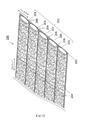
圖1中顯示本發明之碳纖維帶材料的概略圖。Fig. 1 shows a schematic view of the carbon fiber belt material of the present invention.
圖1中所示的碳纖維帶材料100係複數條的碳纖維束101藉由布料103而互相一體化而成者,各自的碳纖維束係在寬度方向中互相平行(並列)地配置,而形成碳纖維束群102。The carbon
本發明所用的碳纖維束例如亦可使用事先施有上漿處理的碳纖維束。藉由施予上漿處理,可提高碳纖維束的集束性,抑制細毛之發生。又,本發明所用的碳纖維束亦可在碳纖維中混合有機纖維。For the carbon fiber bundle used in the present invention, for example, a carbon fiber bundle that has been subjected to a sizing treatment in advance may be used. By applying sizing treatment, the bundling of carbon fiber bundles can be improved and the generation of fine hair can be suppressed. In addition, the carbon fiber bundles used in the present invention may be mixed with organic fibers in carbon fibers.
碳纖維束的長絲(filament)數N(單位:K=1,000條)為1K(1,000)條以上60K(60,000)條以下者係較佳的態樣。碳纖維束101的單纖維數少於1K條時,碳纖維束101之紗寬為細,容易發生扭轉等不良。碳纖維束101的單纖維數多於60K條時,碳纖維束101的碳纖維單位面積重量變高,以纖維鋪放法將碳纖維束101並絲而成為基材時,由於每1層的碳纖維單位面積重量變過高,故有窄化配向設計的容許範圍之虞。The number of filaments N (unit: K=1,000) of the carbon fiber bundle is 1K (1,000) or more and 60K (60,000) or less is a preferred aspect. When the number of single fibers of the
碳纖維帶材料100包含複數條的碳纖維束101,藉由具備與布料103互相一體化之構成,可增大碳纖維帶材料之每單位長度的碳纖維長絲數及重量。又,藉由纖維鋪放法來配置・積層碳纖維帶材料而製造纖維強化塑膠時,可縮短用於成為所欲的纖維體積含量所需要的碳纖維帶材料之配置和積層時間,提高生產性。The carbon
布料103係由1種或複數種類的熱塑性樹脂所構成。此處,所謂熱塑性樹脂,除了聚醯胺樹脂、聚酯樹脂、聚對苯二甲酸乙二酯樹脂、聚乙烯縮甲醛樹脂、聚醚碸樹脂、苯氧基樹脂、聚碳酸酯樹脂等熱塑性樹脂之外,還可更表示熱塑性彈性體(聚苯乙烯系樹脂、聚烯烴系樹脂、聚胺甲酸酯系樹脂、聚酯系樹脂、聚醯胺系樹脂、聚丁二烯系樹脂、聚異戊二烯系樹脂、氟系樹脂及丙烯腈系等),或此等之共聚物、改質體及摻合2種類以上此等樹脂之樹脂等。可使此等樹脂成為纖維狀而形成織布(梭織物、針織物)或不織布之形態,成為薄膜狀而形成布料103。藉由使如此之布料103部分地熔融,而與碳纖維束群102一體化。The
於本發明中,重要的是布料103具有變形性。即,重要的是於布料的至少一方向中,對於該布料施加80mN/50mm之荷重時的布料伸長率為5%~100%,較佳為15%~100%。藉由使用具有變形性的布料,可提高帶的變形性,於以纖維鋪放法直接貼附於模具時,碳纖維帶可跟隨模具形狀。布料伸長率小於5%時,布料不具有充分的變形性,碳纖維帶無法跟隨模具形狀。布料伸長率大於100%時,布料會因稍微的外力而變形,難以在碳纖維上高精度地貼附布料而一體化。此處,布料的伸長率係依據JIS L 1096 8.16.1,以下式求出。In the present invention, it is important that the
Ep
=[(L1 -
L0
)/L0
]×100
Ep
:布料伸長率(%)
L0
:原始記號之間的布料長度(mm)
L1
:荷重賦予時的布料長度(mm)
圖8中顯示布料伸長率之測定方法。圖8(a)表示負載一定荷重之前的布料803之狀態。將布料切割成指定的尺寸,在布料上標註指定的記號808,測定記號間距離L0
後,如圖8(a)所示地藉由夾具807夾住布料。然後,賦予荷重。圖8(b)表示一定荷重賦予後的布料803之狀態。如圖8(b)所示,測定一定荷重賦予後的記號間距離L1
,可藉由指定之式算出伸長率。另外,從將碳纖維束與布料一體化後之帶材料來測定布料的伸長率時,從帶材料剝離布料後,以上述程序進行測定。E p =[(L 1 - L 0 )/L 0 ]×100 E p : Fabric elongation (%) L 0 : Fabric length between original marks (mm) L 1 : Fabric length when load is applied (mm ) Figure 8 shows the measuring method of fabric elongation. Fig. 8(a) shows the state of the
本發明之碳纖維帶材料重要的是去除布料後的單位面積重量在120g/m2 ~400g/m2 之間。碳纖維帶材料之中,去除布料後的單位面積重量小於120g/m2 時,於以纖維鋪放法配置碳纖維帶材料之際,用於得到所欲的單位面積重量之積層體而積層的碳纖維帶材料之片數變多,積層所需要的時間增加,在進一步提高生產性上成為限制。另一方面,碳纖維帶材料之中,去除布料後的單位面積重量大於400g/m2 時,用於得到所欲的單位面積重量之積層體而積層的碳纖維帶材料之片數變過少,有窄化設計纖維配向時的自由度之虞。該單位面積重量較佳為160g/m2 ~300g/m2 。It is important for the carbon fiber belt material of the present invention that the weight per unit area after removing the cloth is between 120 g/m 2 and 400 g/m 2 . Among the carbon fiber tape materials, when the weight per unit area after removing the fabric is less than 120g/m 2 , when the carbon fiber tape material is arranged by the fiber laying method, it is used to obtain the laminated carbon fiber tape of the desired weight per unit area. The number of sheets of materials increases, and the time required for layering increases, which limits the further improvement of productivity. On the other hand, among the carbon fiber tape materials, when the weight per unit area after removing the fabric is greater than 400 g/m 2 , the number of sheets of the carbon fiber tape material to be laminated is too small to obtain a laminate of the desired weight per square meter, which is narrow. The degree of freedom when designing fiber orientation is optimized. The weight per unit area is preferably 160 g/m 2 to 300 g/m 2 .
又,布料103宜具有規則性。於本發明中,所謂「具有規則性」,就是意指某一定的組織形態係在布料的長度方向(即碳纖維帶材料的長度方向)中連續地重複者。作為具有規則性的布料之例,可舉出針織物或梭織物。針織物或梭織物係其組織形態在長度方向中連續地重複,纖維存在的位置係被其組織所規定,因此可說是布料的纖維單位面積重量之偏差或不均少的材料。另一方面,作為不具有規則性的布料之例,可舉出不織布(不織面紗)。不織布由於係使短纖維隨機地散開後,將互相的纖維接著之構成,故難以展現上述的布料伸長率,又,由於其組織形態係不在長度方向中連續地重複,故可舉出容易發生纖維的配向或單位面積重量之偏差和不均之特徵。Furthermore, the
作為具有規則性的布料之組織形態,可使用平織、斜紋織、緞紋織等之織組織、經平組織、簾線、經編緞紋組織、鎖鏈編、鑲嵌、緞織、經絨、六角網眼(tulle)等之經編組織、緯編組織或彼等之組合。As the structure of regular fabrics, weaves such as plain weave, twill weave, satin weave, warp flat weave, cord, warp satin weave, chain knitting, inlay, satin weave, warp, and hexagonal mesh can be used. Warp-knitted weave, weft-knitted weft, etc. of eyes (tulle), or a combination of them.
此等具有規則性的布料係藉由將纖維彼此互相編入或織入而保持形態。即,相較於纖維彼此互相接著而固定相對位置的不織布,經編入或織入的纖維之位置由於未完全地固定而自由度高,結果對於布料的面內(面方向)施力時之變形性優異。These regular fabrics maintain their shape by weaving or weaving fibers into each other. That is, compared to non-woven fabrics in which the fibers are connected to each other to fix the relative positions, the positions of the warp-knitted or woven fibers are not completely fixed and have a higher degree of freedom. As a result, the fabric deforms when a force is applied to the in-plane (surface direction) of the fabric. The sex is excellent.
布料103較佳為單位面積重量大於2g/m2
且為40g/m2
以下,更佳為大於4g/m2
且為20g/m2
以下。布料103的單位面積重量為2g/m2
以下時,布料的坯布容易破損,難以得到所欲的變形性。又,由於布料之厚度變薄,難以充分地確保含浸時的基質樹脂流路。再者,由於布料薄,故成形體中的層間強化材之厚度變薄,難以強化所積層的纖維束之層間。另一方面,布料103的單位面積重量大於40g/m2
時,由於布料之厚度變厚,故碳纖維帶材料的厚度增大,使用碳纖維帶材料的強化纖維積層體之厚度容易比所欲的製品厚度更大,亦即,難以使採用碳纖維帶材料的強化纖維積層精密地接近所欲的成形體。又,使用此強化纖維積層體所成形的成形體係層間強化材的厚度容易變大,難以提高成形體中的纖維含有率(Vf:%)。The
又,布料103係不僅以提高帶的變形性為目,而且以確保樹脂含浸時的基質樹脂流路為目的,或以使用能發揮高韌性的材質之樹脂而強化層間為目的,亦可使用。In addition, the
於構成碳纖維帶材料100之複數的碳纖維束101彼此之間,較佳為設有間隙106。由於在構成碳纖維帶材料100之複數的碳纖維束101間具有間隙106,於以纖維鋪放法成為單向排列的基材時,容易確保基質樹脂的流路。又,於將複數條的碳纖維帶材料100以纖維鋪放法無間隙地單向排列而成為基材時,亦在1條的碳纖維帶材料100內於被固定之複數的碳纖維束101之間設有間隙之情況中,容易確保成形時的基質樹脂之流動性。A
碳纖維束間之間隙106較佳為0.1mm~1mm。間隙106小於0.1mm時,由於基質樹脂的流路變小,成形所需要的時間增加,有造成生產性降低之虞。間隙106大於1mm時,以纖維鋪放法積層碳纖維帶材料而成為強化纖維積層體,進行成形時,上層的帶之一部分落入下層的碳纖維束間之間隙中,有碳纖維束的真直性降低之虞。結果,有所得之成形體的壓縮特性降低之虞。The
碳纖維帶材料100之帶寬度較佳為2mm~2000mm,更佳為5mm~100mm。碳纖維帶材料100之帶寬度小於2mm時,在纖維鋪放步驟中必須配置更多的碳纖維帶材料,生產性容易降低。碳纖維帶材料100之帶寬度大於2000mm時,製造帶的裝置變成大型,造成帶成本之增大而不宜。The belt width of the carbon
圖2所示的碳纖維帶材料200係本發明之另一碳纖維帶材料的示意斜視圖。於此碳纖維帶材料200中,與圖1所示的碳纖維帶材料同樣地,具有規則性的布料203係位於碳纖維束群202之至少單面,但該布料203係以保持各碳纖維束201之形態為目的而以附著於碳纖維束群202之至少單面之樹脂黏結劑204,與碳纖維束群202一體化。其它部分係與圖1所示的碳纖維帶材料100相同之構成。
樹脂黏結劑204可為粒子形狀,也可為不織布形狀。又,不限定於此等之形狀,亦可為薄膜、網目、乳液、塗料或捲繞於碳纖維束的輔助紗。The carbon
作為樹脂黏結劑之材質,除了聚醯胺樹脂、聚酯樹脂、聚對苯二甲酸乙二酯樹脂、聚乙烯縮甲醛樹脂、聚醚碸樹脂、苯氧基樹脂、聚碳酸酯樹脂等熱塑性樹脂之外,另外還可使用酚系樹脂、苯氧基樹脂、環氧樹脂,以及聚苯乙烯系樹脂、聚烯烴系樹脂、聚胺甲酸酯系樹脂、聚酯系樹脂、聚醯胺系樹脂、聚丁二烯系樹脂、聚異戊二烯系樹脂、氟系樹脂及丙烯腈系等熱塑彈性體等,或此等之共聚物、改質體及摻合2種類以上此等樹脂之樹脂等。As the material of the resin binder, in addition to polyamide resin, polyester resin, polyethylene terephthalate resin, polyvinyl formal resin, polyether resin, phenoxy resin, polycarbonate resin and other thermoplastic resins In addition, phenol-based resins, phenoxy resins, epoxy resins, and polystyrene-based resins, polyolefin-based resins, polyurethane-based resins, polyester-based resins, and polyamide-based resins can also be used. , Polybutadiene resins, polyisoprene resins, fluorine resins and acrylonitrile-based thermoplastic elastomers, etc., or these copolymers, modified bodies, and blends of more than 2 types of these resins Resin etc.
此等樹脂黏結劑係除了將成為強化纖維積層體時的層間予以固著之接著功能之外,亦可使用於以確保樹脂含浸時的基質樹脂之流路為目的,或以使用能發揮高韌性的材質之樹脂而強化層間之目的。These resin binders can be used for the purpose of securing the flow path of the matrix resin during resin impregnation, in addition to the adhesion function of fixing the interlayer when the reinforced fiber laminate is formed, or to achieve high toughness. The material of the resin strengthens the purpose of the interlayer.
作為藉由樹脂黏結劑204的碳纖維束201之固定形態,可以能看見樹脂黏結劑204之狀態使其附著和部分含浸於碳纖維束201的表面,拘束碳纖維束中所含有之複數的長絲,又亦可以成為從表面無法看見之狀態的方式,使樹脂黏結劑204含浸至碳纖維束201之內部,互相拘束碳纖維束中所含有之複數的長絲。另外,亦可使樹脂黏結劑捲附於碳纖維束201,或以樹脂黏結劑被覆碳纖維束201。As the fixed form of the
用於固定碳纖維束201所需要的樹脂黏結劑之量,相對於碳纖維束201之重量,較佳為25wt%以下,更佳為20wt%以下,尤佳為15wt%以下。若樹脂黏結劑之量大於25wt%,則藉由纖維鋪放法排列、積層帶材料而成為強化纖維積層體,進行成形時,基質樹脂之黏度升高而流動性容易降低,因此生產性容易降低。又,由於在基質樹脂之流動需要長時間,故基質樹脂黏度進一步上升,在成形體中容易發生樹脂未含浸部位,亦造成成形體的力學特性之變差。The amount of resin binder required for fixing the
布料203之軟化點Ts(℃)較佳為高於樹脂黏結劑204之軟化點。此處,藉由複數種類的熱塑性樹脂構成布料203時,將複數種類的熱塑性樹脂中的軟化點最低的熱塑性樹脂之軟化點視為布料203之軟化點Ts(℃)。此時,以比樹脂黏結劑204之軟化點更高且比布料203之軟化點更低的溫度進行加熱和加壓,將經熔融的樹脂黏結劑204當作接著劑,可使布料203與碳纖維束群202一體化。此時,布料203由於不熔融而保持組織之形態,故不損害布料203所具有的變形性,可得到變形性優異的碳纖維帶材料200。The softening point Ts (°C) of the
又,樹脂黏結劑204較佳為其軟化點(℃)係高於40℃且低於布料203之軟化點Ts(℃)的溫度。藉由使用如此的樹脂黏結劑,於因加熱而黏度降低後,進行冷卻等而回到常溫之狀態時,將構成碳纖維束之複數條的長絲予以互相固定,可確實地保持作為碳纖維束的固定形態。而且,若將碳纖維束之形態保持固定,則藉由纖維鋪放法將碳纖維帶材料200配置於模具上,對於碳纖維帶材料200施加壓力或張力時,可抑制碳纖維束之形態崩壞。結果,可不毀壞碳纖維束201之間所設置的間隙206而保持,可更確實地確保成形時的基質樹脂之流路。In addition, the
另外,於本說明書,所謂「軟化點」,就是指布料、樹脂黏結劑等之樹脂材料在其溫度以上之溫度時,樹脂材料係軟化/熔融之溫度。具體而言,當樹脂材料為結晶性聚合物時,指熔點,當樹脂材料為非晶性聚合物時,指玻璃轉移點。In addition, in this specification, the so-called "softening point" refers to the temperature at which the resin material is softened/melted when the temperature of the resin material such as cloth, resin adhesive, etc. is above its temperature. Specifically, when the resin material is a crystalline polymer, it refers to the melting point, and when the resin material is an amorphous polymer, it refers to the glass transition point.
圖3中顯示本發明之再另一碳纖維帶材料300之示意斜視圖。於此碳纖維帶材料300中,與圖2之態樣同樣地,在將複數的碳纖維束301平行地排列成的碳纖維束群302之至少單面(圖3中為兩面)上,配置具有規則性的布料303。該布料303係以保持各碳纖維束301之形態為目的,以在碳纖維束群302之表面上所附著的樹脂黏結劑304,與碳纖維束群302一體化。而且,於圖3所示之態樣中,於碳纖維束群302之表面所設置的樹脂黏結劑304之中,僅將被接著區域305所包圍的區域之樹脂黏結劑304予以熔融,而貢獻布料303與碳纖維束群302之接著。接著區域305係在碳纖維帶材料300之至少一部分中,於碳纖維束301之纖維配向方向中不連續地而離散地(間歇地)形成。此處所謂「接著區域」,就是表示布料303與碳纖維束群302透過樹脂黏結劑304而互相接著的區域。布料303與碳纖維束群302係藉由在至少一部分的接著區域被接著而互相一體化,可保持碳纖維帶材料之形態。圖3所示的碳纖維帶材料300係除了上述部分以外,為與圖2所示的碳纖維帶材料200相同之構成。FIG. 3 shows a schematic oblique view of still another carbon
於本發明中,接著區域305係如上述地較佳為於碳纖維束301之纖維配向方向中離散地形成。接著區域305在帶全域以及碳纖維束群302與布料303在帶全面中被接著時,構成布料的熱塑性纖維係因與碳纖維束之接著而位置被完全地固定,布料本來具有的變形性降低。圖3中,接著區域305係在纖維配向方向中離散地分散,留下布料局部地自由活動之餘裕,因此可抑制接著所造成的布料變形性之降低。In the present invention, the
再者,以下詳述將接著區域於碳纖維束之纖維配向方向中離散地形成之態樣。圖4(a)、(b)所示的碳纖維帶材料400係本發明之另一碳纖維帶材料的平面圖。於圖4(a)之實施形態中,以樹脂黏結劑使布料與碳纖維束群接著之接著區域405,係在碳纖維帶材料400之全域中,於碳纖維束401之纖維配向方向中離散地形成。於本實施形態中,由於接著區域405係在碳纖維帶材料400之全域中離散地形成,故布料局部地自由活動之餘裕多,可展現優異的帶變形性。於圖4(b)之實施形態中,碳纖維束群402之中,位於與碳纖維束401之纖維配向方向正交的方向之兩端的2條碳纖維束401(a)、401(b),係於碳纖維束之纖維配向方向中連續地與布料403接著,位於2條碳纖維束401(a)、401(b)之間的碳纖維束401(c)、401(d)、401(e),係於碳纖維束之纖維配向方向中間歇地與布料403接著。於本實施形態中,由於位於與碳纖維束之纖維配向方向正交的方向之兩端的2條碳纖維束401(a)、401(b)係連續地與布料403接著,故可抑制布料403從帶端部剝落,可兼顧帶安定性與帶變形性。另外,於此等圖4(a)、(b)所示的碳纖維帶材料400中,各自的接著區域405較佳為以不跨越複數條的碳纖維束之方式設置。Furthermore, the following describes the state where the bonding regions are discretely formed in the fiber alignment direction of the carbon fiber bundles. The carbon
圖5(a)所示的碳纖維帶材料500係本發明之另一碳纖維帶材料的平面圖。在圖5(b)、圖5(c)中分別顯示該碳纖維帶材料500之b-b剖面、c-c-剖面。於本實施形態中,亦以樹脂黏結劑使布料與碳纖維束群接著之接著區域505,係在碳纖維帶材料500之全域中,於碳纖維束501之纖維配向方向中離散地形成。各自的接著區域505係以不跨越複數條的碳纖維束之方式設置。而且,於相鄰的碳纖維束(例如501(a)及501(b))中,接著區域(例如505(a)及505(b))係在碳纖維之纖維配向方向中錯開。於本實施形態中,相鄰的碳纖維束中分別設置的接著區域係藉由在碳纖維之纖維配向方向中錯開,而相鄰的碳纖維束彼此之相對位置不被固定,可獨立地活動。因此,於布料變形之際,碳纖維束可追隨各自接著的布料之部分的活動,而獨立地活動。The carbon
另外,於本發明中,可如圖6(a)般設置接著區域。然而,於圖6(a)所示的碳纖維帶材料600中,在相鄰的碳纖維束(例如碳纖維束601(a)及601(b))中,接著區域(例如接著區域605(a)及605(b))係在碳纖維之纖維配向方向中不錯開。因此,相鄰的碳纖維束彼此的位置會被固定,各自的碳纖維束變難以追隨所接著的布料之部分的活動,難以獨立地活動。因此,與在相鄰的碳纖維束中接著區域在碳纖維之纖維配向方向中不錯開之情況相比,錯開的情況者係可得到變形性高的帶而較宜。另外,圖6(a)係碳纖維帶材料600之平面圖,圖6(b)係碳纖維帶材料600之b-b剖面圖。In addition, in the present invention, a bonding area may be provided as shown in FIG. 6(a). However, in the carbon
而且,如圖5所示,將接著區域505在碳纖維之纖維配向方向中實質地錯開而設置之情況,亦以成為如下為更佳。即,於正交於碳纖維之纖維配向方向的方向之任意剖面中,在相鄰的碳纖維束(例如501(a)及501(b))之上,接著區域(例如505(a)及505(b))不同時地存在。換言之,於相鄰的碳纖維束(例如501(a)及501(b))中,接著區域(例如505(a)及505(b))不是以在碳纖維之纖維配向方向中一部分重疊的方式(如圖5(b)所示),而是以錯開的方式(如圖5(c)所示)設置者較宜。藉由成為如此之構成,碳纖維帶材料可展現更良好的變形性。因此,於碳纖維帶材料500中,成為如圖5(b)所示的剖面之部分,較佳為在碳纖維之纖維配向方向中以一定間隔採集的全部剖面之30%以下之範圍內。Moreover, as shown in FIG. 5, it is more preferable to arrange the
再者,圖7(a)、(b)中顯示本發明之另一碳纖維帶材料700的平面圖。於上述圖3~圖6中,顯示接著區域係在碳纖維束之纖維配向方向中離散地形成之態樣,但於圖7所示的碳纖維帶材料700中,以樹脂黏結劑使布料與碳纖維束群接著之接著區域705,係在正交於碳纖維束之纖維配向方向的方向中離散地形成。藉由如此之構成,相鄰的碳纖維束之相對位置亦不被固定,可獨立地活動,因此碳纖維帶材料可展現良好的變形。Furthermore, Figs. 7(a) and (b) show plan views of another carbon
如以上構成的本發明之碳纖維帶材料係可展現如以下的剪切變形性能。即,使用兩邊抓住法的畫框法,以0°~45°之範圍測定剪切角θ[°]之拉伸荷重F[N]係在剪切角θ[°]為0°~1.0°之間不具有拉伸荷重F[N]的最大值,以0°~45°之範圍測定剪切角θ[°]之拉伸荷重F[N]的最大值大於0.5[N],且在θ[°]為0.1°~1.0°之間,ΔF/Δθ為大於0.1且小於1.0。The carbon fiber tape material of the present invention constructed as above can exhibit the following shear deformation properties. That is, using the frame method of grabbing on both sides and measuring the shear angle θ[°] in the range of 0°~45°, the tensile load F[N] is at the shear angle θ[°] of 0°~1.0 There is no maximum tensile load F[N] between °, and the maximum tensile load F[N] measured at the shear angle θ[°] in the range of 0°~45° is greater than 0.5[N], and When θ[°] is between 0.1° and 1.0°, ΔF/Δθ is greater than 0.1 and less than 1.0.
說明作為剪切變形性能之評價方法之兩邊抓住法的畫框法。圖9顯示兩邊抓住法的畫框法之概略圖。無間隙地平行排列1條或複數條的長度220mm之碳纖維帶材料900,以全寬之和成為150mm之方式準備。以夾持間隔成為200mm之方式,在夾持部902做記號,以夾持部902為200mm,測定角α[°]為90°,以碳纖維帶的長度方向與畫框框架之未抓住碳纖維帶材料的兩邊903呈平行之方式,將碳纖維帶材料900安裝於畫框夾具904,而抓住碳纖維帶兩端之兩邊。在未圖示的萬能試驗機上,以測定角α[°]成為90°之方式安裝畫框夾具後,以50mm/分鐘之速度將畫框夾具在鉛直方向中拉伸,測定當時的拉伸力F[N]及測定角α。然後,算出藉由下式所算出的剪切角θ[°]及θ[°]為0.1°~1.0°之間的ΔF/Δθ。Explains the frame method, which is the two-side grasping method as the evaluation method of shear deformation performance. Fig. 9 shows a schematic diagram of the frame method of grabbing on both sides. One or more carbon
θ[°]=90°-α[°] 圖10中顯示對於本發明之碳纖維帶材料,實施兩邊抓住法的畫框法時之剪切角-拉伸荷重曲線圖的一例。圖10(a)係以0~45試驗剪切角θ[°]時的剪切角-拉伸荷重曲線圖,圖10(b)係放大相同曲線圖的剪切角θ[°]為0~1的附近之曲線圖。θ[°]=90°-α[°] Fig. 10 shows an example of a graph of the shear angle vs. the tensile load when the frame method of the two-side grasping method is applied to the carbon fiber tape material of the present invention. Fig. 10(a) is the shear angle-tension load curve when the test shear angle θ[°] is 0~45, and Fig. 10(b) is an enlarged shear angle θ[°] of the same graph as 0 ~1 near the graph.
於本發明之碳纖維帶材料中,將剪切角θ[°]設為0°~45°而進行試驗時,在剪切角θ[°]為0°~1.0°之間,拉伸荷重F較佳為不具有最大值。當拉伸荷重F[N]的最大值在剪切角θ[°]為0°~1.0°之間時,意指碳纖維帶材料在剪切角θ[°]到達1.0°之前,無法保持形態而崩潰。此時,無法將ΔF/Δθ之值當作碳纖維帶材料的剪切變形性能而進行評價。In the carbon fiber tape material of the present invention, when the shear angle θ[°] is set to 0°~45° and the test is performed, when the shear angle θ[°] is between 0° and 1.0°, the tensile load F Preferably, it does not have a maximum value. When the maximum tensile load F[N] is between the shear angle θ[°] of 0°~1.0°, it means that the carbon fiber tape material cannot maintain its shape before the shear angle θ[°] reaches 1.0° And collapse. At this time, the value of ΔF/Δθ cannot be evaluated as the shear deformation performance of the carbon fiber tape material.
本發明之碳纖維帶材料,係在剪切角θ[°]為0°~1.0°之間拉伸荷重F不具有最大值時,剪切角θ[°]為0.1°~1.0°之間的ΔF/Δθ較佳為小於1.0,更佳為小於0.4,尤佳為小於0.2。ΔF/Δθ為1.0以上時,於將碳纖維帶材料剪切變形時需要大力,以纖維鋪放法並絲而配置到模具時,得不到良好的對於模具之追隨性。另一方面,ΔF/Δθ較佳為大於0.1。ΔF/Δθ為0.1以下時,因賦予些微的力而碳纖維帶材料發生大的剪切變形,會損害碳纖維帶材料的安定性。The carbon fiber tape material of the present invention has a shear angle θ[°] between 0.1° and 1.0° when the tensile load F does not have the maximum value when the shear angle θ[°] is between 0° and 1.0°. ΔF/Δθ is preferably less than 1.0, more preferably less than 0.4, and particularly preferably less than 0.2. When ΔF/Δθ is 1.0 or more, a large force is required for shearing and deforming the carbon fiber tape material, and when the fiber is placed in the mold by the fiber laying method, the followability to the mold cannot be obtained. On the other hand, ΔF/Δθ is preferably greater than 0.1. When ΔF/Δθ is 0.1 or less, the carbon fiber belt material undergoes large shear deformation due to the application of a slight force, and the stability of the carbon fiber belt material is impaired.
本發明之碳纖維帶材料,係將剪切角θ[°]設為0°~45°而進行試驗時,拉伸荷重F的最大值較佳為大於0.5N,更佳為大於1.0N。將剪切角θ[°]設為0°~45°而進行試驗時,於拉伸荷重F的最大值為0.5N以下之情況,碳纖維帶材料係碳纖維束與布材剝離等,無法維持帶形態。For the carbon fiber tape material of the present invention, when the shear angle θ[°] is set to 0°~45° and the test is performed, the maximum tensile load F is preferably greater than 0.5N, more preferably greater than 1.0N. When the shear angle θ[°] is set to 0°~45° and the test is performed, when the maximum tensile load F is 0.5N or less, the carbon fiber belt material is peeled off from the cloth material, and the belt cannot be maintained. form.
而且,於本發明之碳纖維帶材料中,例如如同圖11(a)、(b)所示,將布料1103配置於碳纖維束群1102之兩面,看作全體時較佳為成為筒狀體(圖11(a))或袋狀體(圖11(b))。即如圖11(a),位於與碳纖維束1101之纖維配向方向正交的方向之兩端的2條碳纖維束1101(a)、1101(b),較佳為在其兩面與布料1103接著,以兩端的碳纖維束1101(a)、1101(b)與兩面的布料1103形成筒狀的封閉系統。藉由成為如此,可防止內側3條碳纖維束1101(c)、1101(d)、1101(e)之脫落。又,基於同樣之理由,如圖11(b),亦較佳為以內包碳纖維束1101之方式配置布料1103。如此地,藉由將布料配置於碳纖維束群之兩面,於碳纖維帶材料之操作中可抑制碳纖維束脫離,可提高碳纖維帶材料的生產安定性。Furthermore, in the carbon fiber belt material of the present invention, as shown in Figs. 11(a) and (b), for example, the
本發明之碳纖維帶材料係用於強化纖維積層體。強化纖維積層體係藉由排列和積層本發明之碳纖維帶材料,固著其層間的至少一部分而保持形狀。由於採取如此之構成,可將構成強化纖維積層體的碳纖維束彼此之間隙設定在任意的距離,進行配置。結果,可確保成形時的基質樹脂之流動性,可增加所注入的樹脂之種類或製程窗(process window)之寬度等,可提高生產性。The carbon fiber tape material of the present invention is used for reinforcing fiber laminates. The reinforced fiber laminate system maintains its shape by arranging and laminating the carbon fiber tape material of the present invention, and fixing at least a part of the interlayer. With such a configuration, the gap between the carbon fiber bundles constituting the reinforced fiber laminate can be set at an arbitrary distance and arranged. As a result, the fluidity of the matrix resin during molding can be ensured, the type of resin injected or the width of the process window can be increased, and the productivity can be improved.
又,於使用碳纖維帶材料的強化纖維積層體中,較佳為含浸基質樹脂而成為纖維強化樹脂成形體。藉由採取前述構成,所得之纖維強化樹脂成形體係樹脂完全地含浸到其內部,可具有高力學特性。 [實施例]In addition, in the reinforced fiber laminate using the carbon fiber tape material, it is preferable to impregnate matrix resin to form a fiber reinforced resin molded body. By adopting the aforementioned structure, the resulting fiber-reinforced resin molding system resin is completely impregnated into its interior and can have high mechanical properties. [Example]
以實施例為基礎,說明本發明之碳纖維帶材料。表1中顯示實施例及比較例之條件及結果。Based on the examples, the carbon fiber belt material of the present invention will be described. Table 1 shows the conditions and results of Examples and Comparative Examples.
(實施例1) <強化纖維束> 作為強化纖維束,使用預先施有上漿處理之東麗股份有限公司製碳纖維「Torayca」(註冊商標)T800SC,碳纖維長絲數為24,000條(N=24K)。(Example 1) <Reinforced fiber bundle> As the reinforcing fiber bundle, carbon fiber "Torayca" (registered trademark) T800SC made by Toray Co., Ltd., which had been sizing treated in advance, was used, and the number of carbon fiber filaments was 24,000 (N=24K).
<布料> 作為布料,使用採用經編機經編成六角網眼組織狀之具有規則性的針織物(材質:聚醯胺,單位面積重量:8g/m2 )。<Fabric> As the fabric, a regular knitted fabric (material: polyamide, weight per unit area: 8g/m 2 ) that was warp-knitted into a hexagonal mesh structure using a warp knitting machine was used.
<布料的伸長率測定> 布料的伸長率係參考JIS L 1096 8.16.1,如以下地測定。即,以前述布料的縱行(wale)方向成為長度方向之方式,切割成寬度50mm、長度300mm,以夾持間隔成為200mm之方式,在夾持部做記號。以夾具固定試驗片的一端後,平靜地賦予80mN/50mm之荷重,測定1分鐘保持後的記號之間的長度。由下式算出布料伸長率,結果伸長率為52%。<Measurement of fabric elongation> The elongation of the fabric refers to JIS L 1096 8.16.1, and is measured as follows. That is, the cloth was cut into a width of 50 mm and a length of 300 mm so that the wale direction of the aforementioned cloth became the longitudinal direction, and the nip portion was marked so that the nip interval became 200 mm. After fixing one end of the test piece with a jig, a load of 80mN/50mm was calmly applied, and the length between the marks after holding for 1 minute was measured. The fabric elongation was calculated from the following formula, and the elongation was 52%.
Ep =[(L1 - L0 )/L0 ]×100 Ep :布料伸長率(%) L0 :原始記號之間的布料長度(mm) L1 :荷重賦予時的布料長度(mm) <碳纖維帶材料> 使用未圖示的碳纖維束製造裝置,從筒管拉出碳纖維束1條,邊調整厚度邊在不使其分裂下將寬度弄窄,然後將軟化點溫度80℃的加熱熔融性之黏結劑粒子(平均粒徑:0.2mm)散布於碳纖維束之表面。以黏結劑粒子之重量比例成為5%(將所得之碳纖維束的重量當作100%)之方式散布後,進行熔融、冷卻,而得到其形態經固定的紗寬4.8mm之碳纖維束。E p =[(L 1 - L 0 )/L 0 ]×100 E p : Fabric elongation (%) L 0 : Fabric length between original marks (mm) L 1 : Fabric length when load is applied (mm ) <Carbon fiber tape material> Using a carbon fiber bundle manufacturing device not shown in the figure, pull out one carbon fiber bundle from the bobbin, adjust the thickness while narrowing the width without splitting it, and then heat the softening point at 80°C Fusible binder particles (average particle size: 0.2mm) are scattered on the surface of the carbon fiber bundle. After being dispersed so that the weight ratio of the binder particles becomes 5% (the weight of the obtained carbon fiber bundle is regarded as 100%), it is melted and cooled to obtain a carbon fiber bundle with a fixed shape and a yarn width of 4.8 mm.
將10條碳纖維束在長度方向中平行地並絲後,在其單面上配置軟化點溫度200℃的針織物(布料),以120℃加熱而將黏結劑粒子熔融,將針織物與碳纖維束,透過黏結劑粒子以成為如圖4(b)之方式進行部分接著(在兩端以外的碳纖維束上,將黏結劑粒子設為直徑4.5mm的球狀體而交錯狀配置,在兩端的2條碳纖維束上全面配置黏結劑粒子)而使其一體化。藉由這樣做,得到寬度50mm、去除布料後的帶單位面積重量為206g/m2 、碳纖維束間的各間隙為0.2mm之碳纖維帶材料。After 10 carbon fiber bundles are combined in parallel in the longitudinal direction, a knitted fabric (cloth) with a softening point temperature of 200°C is placed on one side, and the binder particles are heated at 120°C to fuse the knitted fabric and the carbon fiber bundles. , Through the binder particles to become part of the bonding as shown in Figure 4 (b) (on the carbon fiber bundles other than the ends, the binder particles are arranged as spheres with a diameter of 4.5 mm and arranged in a staggered manner. 2 The carbon fiber bundles are fully equipped with binder particles) to integrate them. By doing this, a carbon fiber tape material with a width of 50 mm, a belt unit weight after removing the cloth of 206 g/m 2 , and a gap between the carbon fiber bundles of 0.2 mm was obtained.
<碳纖維帶材料之變形性> 作為碳纖維帶材料之變形性評價,實施兩邊抓住法的畫框法。平行地排列3條長度220mm、寬度50mm的碳纖維帶材料,以夾持間隔成為200mm之方式在夾持部做記號。然後,將3條平行地排列之碳纖維帶材料,以夾持部成為200mm、測定角α[°]成為90°之方式,安裝於圖9所示的畫框夾具,使其抓住兩邊,實施測定。結果,剪切角θ[°]為0°~45°之範圍中的拉伸荷重F[N]係最大值大於0.5[N],且該最大值係不存在於剪切角θ[°]為0°~1.0°之間。而且,成為ΔF/Δθ=0.3,確認碳纖維帶材料係對於面內的剪切力,顯示良好的變形性。<Deformability of carbon fiber tape material> As an evaluation of the deformability of the carbon fiber tape material, the frame method of grabbing on both sides was implemented. Arrange three carbon fiber tape materials with a length of 220 mm and a width of 50 mm in parallel, and mark the clamping part so that the clamping interval becomes 200 mm. Then, the three carbon fiber tape materials arranged in parallel are mounted on the frame jig shown in Fig. 9 so that the clamping part becomes 200mm and the measurement angle α[°] becomes 90°. Determination. As a result, the maximum value of the tensile load F[N] in the range of the shear angle θ[°] from 0° to 45° is greater than 0.5[N], and the maximum value does not exist at the shear angle θ[°] Between 0° and 1.0°. Furthermore, ΔF/Δθ=0.3, which confirms that the carbon fiber tape material has good deformability with respect to in-plane shearing force.
<強化纖維積層體> 使用未圖示的纖維鋪放裝置,在架台上,將如上述所得之碳纖維帶材料,以在各自的碳纖維帶材料間分別設置0.7mm之間隙的方式,於一方向中並絲及配置,以成為300mm×300mm的正方形形狀之方式邊切斷碳纖維帶材料邊重複配置而製作薄片基材。相鄰的碳纖維帶材料係使相鄰的針織物重疊1mm,藉由200℃加熱重疊部而接著一體化,製作薄片基材。<Reinforced fiber laminate> Using a fiber placement device not shown in the figure, on the stand, the carbon fiber tape materials obtained as described above are combined and arranged in one direction with a gap of 0.7 mm between the respective carbon fiber tape materials. The carbon fiber tape material was cut to form a square shape of 300 mm×300 mm while repeating the arrangement to produce a sheet base material. Adjacent carbon fiber tape materials overlap adjacent knitted fabrics by 1 mm, and heat the overlapped portions at 200° C. and then integrate them to produce a sheet base material.
將所得之薄片基材配置於稜錐(四面體)形狀之模具(底面:1邊為14cm的正三角形,高度:7cm),一邊將張力施予薄片基材,一邊下降上模而加壓賦形後,以120℃加熱下模10分鐘。結果,薄片基材係不引入大的皺紋,顯示良好的賦形性。以同樣的程序,將薄片基材在稜錐形狀的模具中每1層地依序賦形後,關閉上模後,以120℃加熱下模10分鐘。結果,不引入大的皺紋,得到良好的強化纖維積層體。The obtained sheet substrate was placed in a pyramid (tetrahedral) mold (bottom: an equilateral triangle with 14 cm on one side, height: 7 cm), and while tension was applied to the sheet substrate, the upper mold was lowered to apply pressure. After shaping, the lower mold was heated at 120°C for 10 minutes. As a result, the sheet base material does not introduce large wrinkles and exhibits good shaping properties. In the same procedure, the sheet substrate was formed in a pyramid-shaped mold for each layer in sequence, the upper mold was closed, and the lower mold was heated at 120°C for 10 minutes. As a result, no large wrinkles are introduced, and a good reinforced fiber laminate is obtained.
<成形體> 將所得之強化纖維積層體配置於前述稜錐形狀之下模,使用包裝膜進行真空包裝後,在環境溫度100℃的烘箱內配置模具。然後,將基質樹脂(環氧樹脂)注入,在180℃環境下硬化。結果,得到無樹脂未含浸部位之良好的成形體。<Molded body> The obtained reinforced fiber laminate was placed on the aforementioned pyramid-shaped lower mold, and after vacuum packaging with a packaging film, the mold was placed in an oven at an ambient temperature of 100°C. Then, the matrix resin (epoxy resin) is injected and cured in an environment of 180°C. As a result, a good molded body is obtained without a portion not impregnated with resin.
(實施例2) 除了以下部分以外,與實施例1同樣地得到碳纖維帶。 ・作為布料,使用採用經編機經編成鎖鏈+經絨組織狀之具有規則性的針織物(材質:聚醯胺,單位面積重量:10g/m2 )。(Example 2) A carbon fiber tape was obtained in the same manner as in Example 1 except for the following parts.・As the fabric, use a regular knitted fabric (material: polyamide, weight per unit area: 10g/m 2 ) that is warp-knitted by a warp knitting machine into a chain + warp structure.
<布料的伸長率測定> 以與實施例1同樣之方法測定伸長率,結果縱行方向的伸長率為35%。<Measurement of fabric elongation> The elongation was measured by the same method as in Example 1. As a result, the elongation in the wale direction was 35%.
<碳纖維帶材料之變形性> 以與實施例1同樣之方法,實施兩邊抓住法的畫框法,結果剪切角θ[°]為0°~45°之範圍中的拉伸荷重F[N]係最大值大於0.5[N],且該最大值係不存在於剪切角θ[°]為0°~1.0°之間。而且,成為ΔF/Δθ=0.37,確認碳纖維帶材料係對於面內的剪切力,顯示良好的變形性。<Deformability of carbon fiber tape material> In the same way as in Example 1, the frame method of grabbing on both sides was implemented. As a result, the maximum tensile load F[N] was greater than 0.5[ N], and the maximum value does not exist when the shear angle θ[°] is between 0° and 1.0°. Furthermore, ΔF/Δθ=0.37, which confirms that the carbon fiber tape material has good deformability with respect to in-plane shearing force.
<強化纖維積層體> 以與實施例1同樣之方法實施,結果薄片基材不發生浪紋或皺紋,得到良好的強化纖維積層體。 <成形體> 以與實施例1同樣之方法實施,結果得到無樹脂未含浸部位之良好的成形體。<Reinforced fiber laminate> It was carried out in the same manner as in Example 1. As a result, no waves or wrinkles were generated on the sheet base material, and a good reinforced fiber laminate was obtained. <Molded body> It was implemented in the same manner as in Example 1, and as a result, a good molded body without resin impregnated parts was obtained.
(實施例3) 除了以下部分以外,與實施例1同樣地得到碳纖維帶。 ・以與實施例1同樣之方法,得到形態經固定的紗寬3.5mm之碳纖維束後,將10條碳纖維束在長度方向中平行地並絲,將碳纖維束間之各間隙調整到約0.3mm,最後所得之碳纖維帶材料的寬度成為38mm,去除布料後的帶單位面積重量成為271g/m2 。 ・針織物與碳纖維束係透過黏結劑粒子,如圖4(a)般進行部分接著(將黏結劑粒子設為直徑4.5mm的球狀體,交錯狀配置),使其一體化。(Example 3) A carbon fiber tape was obtained in the same manner as in Example 1 except for the following parts.・In the same way as in Example 1, after obtaining a fixed form of carbon fiber bundles with a yarn width of 3.5 mm, 10 carbon fiber bundles were paralleled in the longitudinal direction, and the gaps between the carbon fiber bundles were adjusted to about 0.3 mm , The width of the resulting carbon fiber tape material becomes 38mm, and the weight per unit area of the tape after removing the fabric becomes 271g/m 2 .・The knitted fabric and the carbon fiber bundles penetrate through the binder particles, and are partially bonded as shown in Figure 4(a) (the binder particles are made into spheres with a diameter of 4.5 mm and arranged in a staggered pattern) to integrate them.
<碳纖維帶材料之變形性> 以與實施例1同樣之方法,實施兩邊抓住法的畫框法,結果剪切角θ[°]為0°~45°之範圍中的拉伸荷重F[N]係最大值大於0.5[N],且該最大值係不存在於剪切角θ[°]為0°~1.0°之間。而且,成為ΔF/Δθ=0.17,確認碳纖維帶材料係對於面內的剪切力,顯示良好的變形性<Deformability of carbon fiber tape material> In the same way as in Example 1, the frame method of grabbing on both sides was implemented. As a result, the maximum tensile load F[N] was greater than 0.5[ N], and the maximum value does not exist when the shear angle θ[°] is between 0° and 1.0°. Moreover, it becomes ΔF/Δθ=0.17, confirming that the carbon fiber tape material has good deformability against in-plane shearing force.
<強化纖維積層體> 以與實施例1同樣之方法實施,結果薄片基材不發生浪紋或皺紋,得到良好的強化纖維積層體。 <成形體> 以與實施例1同樣之方法實施,結果得到無樹脂未含浸部位之良好的成形體。<Reinforced fiber laminate> It was carried out in the same manner as in Example 1. As a result, no waves or wrinkles were generated on the sheet base material, and a good reinforced fiber laminate was obtained. <Molded body> It was implemented in the same manner as in Example 1, and as a result, a good molded body without resin impregnated parts was obtained.
(實施例4) 除了以下部分以外,與實施例1同樣地得到碳纖維帶。 ・以與實施例1同樣之方法,得到形態經固定的紗寬7.0mm之碳纖維束後,將5條碳纖維束在長度方向中平行地並絲,將碳纖維束間之各間隙調整到約0.7mm,最後所得之碳纖維帶材料的寬度成為38mm,去除布料後的帶單位面積重量成為135g/m2 。 ・針織物與碳纖維束係透過黏結劑粒子,如圖7(a)般在正交於碳纖維束的纖維配向的方向中離散地部分接著(於各碳纖維束(寬度7mm)之中,將從中心起5mm寬度部分在長度方向中連續接著),使其一體化。(Example 4) A carbon fiber tape was obtained in the same manner as in Example 1 except for the following parts.・Using the same method as Example 1, after obtaining a carbon fiber bundle with a fixed shape and a yarn width of 7.0mm, the 5 carbon fiber bundles were paralleled in the longitudinal direction, and the gaps between the carbon fiber bundles were adjusted to about 0.7mm , The width of the resulting carbon fiber belt material becomes 38mm, and the weight of the belt unit area after removing the cloth becomes 135g/m 2 .・Knitted fabric and carbon fiber bundles penetrate the binder particles, and discretely partially adhere in the direction orthogonal to the fiber alignment of the carbon fiber bundles as shown in Figure 7(a) (in each carbon fiber bundle (width 7mm), from the center The 5mm width part is continuously connected in the longitudinal direction) to be integrated.
<碳纖維帶材料之變形性> 以與實施例1同樣之方法,實施兩邊抓住法的畫框法,結果剪切角θ[°]為0°~45°之範圍中的拉伸荷重F[N]係最大值大於0.5[N],且該最大值係不存在於剪切角θ[°]為0°~1.0°之間。而且,成為ΔF/Δθ=0.33,確認碳纖維帶材料係對於面內的剪切力,顯示良好的變形性。<Deformability of carbon fiber tape material> In the same way as in Example 1, the frame method of grabbing on both sides was implemented. As a result, the maximum tensile load F[N] was greater than 0.5[ N], and the maximum value does not exist when the shear angle θ[°] is between 0° and 1.0°. Furthermore, ΔF/Δθ=0.33, which confirms that the carbon fiber tape material has good deformability with respect to in-plane shearing force.
<強化纖維積層體> 以與實施例1同樣之方法實施,結果薄片基材不發生浪紋或皺紋,得到良好的強化纖維積層體。<Reinforced fiber laminate> It was carried out in the same manner as in Example 1. As a result, no waves or wrinkles were generated on the sheet base material, and a good reinforced fiber laminate was obtained.
<成形體> 以與實施例1同樣之方法實施,結果得到無樹脂未含浸部位之良好的成形體。<Molded body> It was implemented in the same manner as in Example 1, and as a result, a good molded body without resin impregnated parts was obtained.
(實施例5) 除了以下部分以外,與實施例1同樣地得到碳纖維帶。 ・作為布料,使用Spunfab公司製不織布(材質:聚醯胺,單位面積重量:6g/m2 )。 ・以與實施例1同樣之方法,得到形態經固定的紗寬3.5mm之碳纖維束後,將10條碳纖維束在長度方向中平行地並絲,將碳纖維束間之各間隙調整到0.3mm,最後所得之碳纖維帶材料的寬度成為38mm,去除布料後的帶單位面積重量成為271g/m2 。 ・不織布與碳纖維束係透過黏結劑粒子,如圖4(a)般進行部分接著(將黏結劑粒子設為直徑4.5mm的球狀體,交錯狀配置),使其一體化。(Example 5) A carbon fiber tape was obtained in the same manner as in Example 1 except for the following parts.・As the fabric, a non-woven fabric made by Spunfab (material: polyamide, weight per unit area: 6g/m 2 ) is used.・In the same manner as in Example 1, after obtaining a fixed form of carbon fiber bundles with a yarn width of 3.5 mm, 10 carbon fiber bundles were paralleled in the longitudinal direction, and the gaps between the carbon fiber bundles were adjusted to 0.3 mm. The width of the resulting carbon fiber tape material was 38 mm, and the weight of the tape per unit area after removing the cloth was 271 g/m 2 .・The non-woven fabric and the carbon fiber bundles penetrate through the binder particles and are partially bonded as shown in Figure 4(a) (the binder particles are made into spheres with a diameter of 4.5 mm and arranged in a staggered pattern) to integrate them.
<布料的伸長率測定> 以與實施例1同樣之方法測定伸長率,結果縱行方向的伸長率為10%,得到良好的變形性。<Measurement of fabric elongation> The elongation was measured by the same method as in Example 1. As a result, the elongation in the wale direction was 10%, and good deformability was obtained.
<碳纖維帶材料之變形性> 以與實施例1同樣之方法,實施兩邊抓住法的畫框法,結果剪切角θ[°]為0°~45°之範圍中的拉伸荷重F[N]係最大值大於0.5[N],且該最大值係不存在於剪切角θ[°]為0°~1.0°之間。而且,成為ΔF/Δθ=0.23,確認碳纖維帶材料係對於面內的剪切力,顯示良好的變形性。<Deformability of carbon fiber tape material> In the same way as in Example 1, the frame method of grabbing on both sides was implemented. As a result, the maximum tensile load F[N] was greater than 0.5[ N], and the maximum value does not exist when the shear angle θ[°] is between 0° and 1.0°. Furthermore, ΔF/Δθ=0.23, which confirms that the carbon fiber tape material has good deformability with respect to in-plane shearing force.
<強化纖維積層體> 以與實施例1同樣之方法實施,結果薄片基材不發生浪紋或皺紋,得到良好的強化纖維積層體。<Reinforced fiber laminate> It was carried out in the same manner as in Example 1. As a result, no waves or wrinkles were generated on the sheet base material, and a good reinforced fiber laminate was obtained.
<成形體> 以與實施例1同樣之方法實施,結果得到無樹脂未含浸部位之良好的成形體。<Molded body> It was implemented in the same manner as in Example 1, and as a result, a good molded body without resin impregnated parts was obtained.
(比較例1) 除了以下部分以外,與實施例1同樣地得到碳纖維帶。 ・作為布料,使用Spunfab公司製不織布(材質:聚醯胺,軟化點溫度:130℃,單位面積重量:10g/m2 )。 ・將黏結劑粒子未附著之10條碳纖維束在長度方向中平行地並絲後,在其單面上配置軟化點溫度130℃之不織布,以130℃加熱而將不織布熔融,使不織布與碳纖維束全面接著而一體化。藉由這樣做,得到寬度為50mm、去除布料後的帶單位面積重量為206g/m2 、碳纖維束間的各間隙為0.2mm之碳纖維帶材料。(Comparative Example 1) A carbon fiber tape was obtained in the same manner as in Example 1 except for the following parts.・As the fabric, a non-woven fabric made by Spunfab (material: polyamide, softening point temperature: 130°C, weight per unit area: 10g/m 2 ) is used.・After 10 carbon fiber bundles with no binder particles attached are paralleled in the longitudinal direction, a non-woven fabric with a softening point temperature of 130°C is placed on one side, and the non-woven fabric is heated at 130°C to melt the non-woven fabric and the carbon fiber bundle. Comprehensive follow-up and integration. By doing so, a carbon fiber tape material with a width of 50 mm, a belt unit weight after removing the cloth of 206 g/m 2 , and a gap between the carbon fiber bundles of 0.2 mm was obtained.
<布料的伸長率測定> 以與實施例1同樣之方法測定伸長率,結果縱行方向的伸長率為3%,得不到良好的變形性。<Measurement of fabric elongation> The elongation was measured by the same method as in Example 1. As a result, the elongation in the wale direction was 3%, and good deformability was not obtained.
<碳纖維帶材料之變形性> 以與實施例1同樣之方法,實施兩邊抓住法的畫框法,結果剪切角θ[°]為0°~45°之範圍中的拉伸荷重F[N]係最大值大於0.5[N],且該最大值係不存在於剪切角θ[°]為0°~1.0°之間。而且,成為ΔF/Δθ=1.2,確認碳纖維帶材料係對於面內的剪切力,不顯示良好的變形性。<Deformability of carbon fiber tape material> In the same way as in Example 1, the frame method of grabbing on both sides was implemented. As a result, the maximum tensile load F[N] was greater than 0.5[ N], and the maximum value does not exist when the shear angle θ[°] is between 0° and 1.0°. Furthermore, ΔF/Δθ=1.2, which confirms that the carbon fiber tape material does not exhibit good deformability with respect to in-plane shearing force.
<強化纖維積層體> 以與實施例1同樣之方法實施,結果在薄片基材看到浪紋或皺紋,得不到良好的強化纖維積層體。<Reinforced fiber laminate> It was implemented in the same manner as in Example 1. As a result, waves or wrinkles were seen on the sheet base material, and a good reinforced fiber laminate could not be obtained.
<成形體> 以與實施例1同樣之方法實施,結果得到在皺紋發生的地方有樹脂未含浸部位之成形體。<Molded body> It was carried out in the same manner as in Example 1, and as a result, a molded body was obtained in which the wrinkle occurred in the portion where the resin was not impregnated.
[表1]
本發明之碳纖維帶材料或使用其之強化纖維積層體,由於基質樹脂的含浸性優異,故使用該強化纖維積層體所得之成形體係尤其對於以航空機或汽車、船舶等為取向的大型構件,或如風車葉片之一般產業用途的構件,亦可適用。The carbon fiber tape material of the present invention or the reinforced fiber laminate using the same has excellent matrix resin impregnation properties. Therefore, the molding system obtained by using the reinforced fiber laminate is particularly suitable for large-scale components oriented to aircraft, automobiles, ships, etc., or Components for general industrial purposes such as windmill blades are also applicable.
100,200,300,400,500,900,1100:碳纖維帶材料
101,201,301,401,501,601,1101:碳纖維束
102,202,302,402,1102:碳纖維束群
103,203,303,403,503,603,703,803,1103:布料
106,206,306:間隙
204,304,1104:樹脂黏結劑
305,405,505,605,705,1105:接著區域
807:夾具
808:記號
902:夾持部
903:未抓住碳纖維帶材料的兩邊
904:畫框夾具100, 200, 300, 400, 500, 900, 1100: carbon fiber tape material
101,201,301,401,501,601,1101:
圖1係本發明之碳纖維帶材料的概略圖。 圖2係本發明之另一碳纖維帶材料的概略圖。 圖3係本發明之另一碳纖維帶材料的概略圖。 圖4係本發明之另一碳纖維帶材料的概略圖。 圖5係本發明之另一碳纖維帶材料的概略圖。 圖6係本發明之另一碳纖維帶材料的概略圖。 圖7係本發明之另一碳纖維帶材料的概略圖。 圖8係顯示布料伸長率之測定方法的概略圖。 圖9係顯示藉由兩邊抓住法的畫框法之實施方法的概略圖。 圖10係顯示兩邊抓住法的畫框法實施時之剪切角-拉伸荷重的關係之曲線圖。 圖11係本發明之另一碳纖維帶材料的概略圖。Fig. 1 is a schematic view of the carbon fiber belt material of the present invention. Fig. 2 is a schematic view of another carbon fiber belt material of the present invention. Fig. 3 is a schematic view of another carbon fiber belt material of the present invention. Fig. 4 is a schematic view of another carbon fiber tape material of the present invention. Fig. 5 is a schematic view of another carbon fiber tape material of the present invention. Fig. 6 is a schematic view of another carbon fiber tape material of the present invention. Fig. 7 is a schematic view of another carbon fiber tape material of the present invention. Fig. 8 is a schematic diagram showing a method for measuring the elongation of a fabric. Fig. 9 is a schematic diagram showing the implementation method of the frame method by grasping on both sides. Fig. 10 is a graph showing the relationship between the shear angle and the tensile load when the frame method of the two-side grasping method is implemented. Fig. 11 is a schematic view of another carbon fiber tape material of the present invention.
100:碳纖維帶材料 100: Carbon fiber belt material
101:碳纖維束 101: Carbon fiber bundle
102:碳纖維束群 102: Carbon fiber bundle group
103:布料 103: Cloth
106:間隙 106: gap
Claims (14)
Applications Claiming Priority (4)
| Application Number | Priority Date | Filing Date | Title |
|---|---|---|---|
| JP2019203907 | 2019-11-11 | ||
| JP2019203908 | 2019-11-11 | ||
| JP2019-203908 | 2019-11-11 | ||
| JP2019-203907 | 2019-11-11 |
Publications (1)
| Publication Number | Publication Date |
|---|---|
| TW202124135A true TW202124135A (en) | 2021-07-01 |
Family
ID=75911486
Family Applications (1)
| Application Number | Title | Priority Date | Filing Date |
|---|---|---|---|
| TW109138968A TW202124135A (en) | 2019-11-11 | 2020-11-09 | Carbon fiber tape material, and reinforced fiber laminate and molded article using same |
Country Status (7)
| Country | Link |
|---|---|
| US (1) | US20220379523A1 (en) |
| EP (1) | EP4059685A4 (en) |
| JP (1) | JPWO2021095623A1 (en) |
| CN (1) | CN114616090B (en) |
| AU (1) | AU2020383077A1 (en) |
| TW (1) | TW202124135A (en) |
| WO (1) | WO2021095623A1 (en) |
Family Cites Families (18)
| Publication number | Priority date | Publication date | Assignee | Title |
|---|---|---|---|---|
| JP3505754B2 (en) * | 1993-12-02 | 2004-03-15 | 東レ株式会社 | Prepreg and manufacturing method thereof |
| JP2791875B2 (en) * | 1996-01-31 | 1998-08-27 | 川崎重工業株式会社 | Highly impregnated three-dimensional fabric, carbon fiber reinforced composite material and ceramic composite material using the fabric |
| KR20010014068A (en) * | 1997-07-23 | 2001-02-26 | 사가라 아스히코 | Unidirectional reinforcing fiber composite substrate |
| EP1125728B1 (en) * | 1999-03-23 | 2011-10-05 | Toray Industries, Inc. | Composite reinforcing fiber base material, preform and production method for fiber reinforced plastic |
| JP2001064406A (en) * | 1999-08-31 | 2001-03-13 | Toray Ind Inc | Preform for fiber-reinforced preform and fiber- reinforced composite material using the same and production thereof |
| FR2939069B1 (en) | 2008-11-28 | 2013-03-01 | Hexcel Reinforcements | NEW INTERMEDIATE MATERIAL OF CONSTANT WIDTH FOR THE PRODUCTION OF COMPOSITE PARTS BY DIRECT PROCESS. |
| US9050906B2 (en) * | 2010-07-23 | 2015-06-09 | Nissan Motor Co., Ltd. | Abnormal torque evaluation apparatus for electrically driven vehicle |
| DE102010050079A1 (en) * | 2010-10-29 | 2012-05-03 | Premium Aerotec Gmbh | Partially fixed semi-finished textile |
| KR101931826B1 (en) * | 2010-12-24 | 2018-12-21 | 도레이 카부시키가이샤 | Method for producing carbon fiber aggregate, and method for producing carbon fiber-reinforced plastic |
| US10059079B2 (en) * | 2011-10-24 | 2018-08-28 | Hanwha Azdel, Inc. | Deep draw composites and methods of using them |
| JP6284310B2 (en) * | 2013-07-12 | 2018-02-28 | 株式会社クラレ | Fiber base tape or sheet, method for producing the same, and fiber reinforced composite material |
| JP5994060B2 (en) | 2013-11-15 | 2016-09-21 | 八田経編株式会社 | Thermoplastic resin reinforced sheet material and method for producing the same |
| JP6654632B2 (en) | 2014-06-30 | 2020-02-26 | サイテック インダストリーズ インコーポレイテッド | Dry fiber tape for preform production |
| GB201417769D0 (en) * | 2014-10-08 | 2014-11-19 | Rolls Royce Plc | Composite article |
| ES2637712T3 (en) * | 2014-11-21 | 2017-10-16 | Tape Weaving Sweden Ab | Tape-type dry fiber reinforcement |
| EP3112111A1 (en) * | 2015-07-02 | 2017-01-04 | Honda Motor Co., Ltd. | A fiber tape for producing fiber reinforced parts and process for manufacturing such a fiber tape |
| CN108291044A (en) * | 2015-12-25 | 2018-07-17 | 东丽株式会社 | Prepreg and its manufacturing method |
| CN109715385B (en) * | 2016-09-14 | 2021-04-27 | 三菱化学株式会社 | Laminated substrate and method for producing same |
-
2020
- 2020-11-05 JP JP2020564017A patent/JPWO2021095623A1/ja active Pending
- 2020-11-05 WO PCT/JP2020/041312 patent/WO2021095623A1/en unknown
- 2020-11-05 US US17/773,639 patent/US20220379523A1/en active Pending
- 2020-11-05 CN CN202080075938.3A patent/CN114616090B/en active Active
- 2020-11-05 AU AU2020383077A patent/AU2020383077A1/en active Pending
- 2020-11-05 EP EP20886404.1A patent/EP4059685A4/en active Pending
- 2020-11-09 TW TW109138968A patent/TW202124135A/en unknown
Also Published As
| Publication number | Publication date |
|---|---|
| AU2020383077A1 (en) | 2022-06-09 |
| CN114616090B (en) | 2024-04-05 |
| EP4059685A1 (en) | 2022-09-21 |
| EP4059685A4 (en) | 2023-12-20 |
| JPWO2021095623A1 (en) | 2021-05-20 |
| US20220379523A1 (en) | 2022-12-01 |
| CN114616090A (en) | 2022-06-10 |
| WO2021095623A1 (en) | 2021-05-20 |
Similar Documents
| Publication | Publication Date | Title |
|---|---|---|
| KR101260088B1 (en) | Reinforcing woven fabric and process for producing the same | |
| WO2016006543A1 (en) | Pseudo-isotropic reinforced sheet material and method for producing same | |
| EP2642007A1 (en) | Method for producing carbon fiber aggregate, and method for producing carbon fiber-reinforced plastic | |
| JP6965957B2 (en) | Laminated base material, its manufacturing method, and carbon fiber reinforced resin base material | |
| CN112313055B (en) | Prepreg and method for producing same, fiber-reinforced composite molded article and method for producing same, and method for producing preform | |
| JP2014004797A (en) | Composite material for molding and method for producing the same | |
| AU2018293693B2 (en) | Materials comprising shape memory alloy wires and methods of making these materials | |
| EP4140710A1 (en) | Reinforced fiber tape material and production method therefor, fiber reinforced resin | |
| EP3960796A1 (en) | Method for manufacturing molded article of fiber-reinforced composite material, reinforcing fiber substrate and molded article of fiber-reinforced composite material | |
| TW202124135A (en) | Carbon fiber tape material, and reinforced fiber laminate and molded article using same | |
| CA3008119C (en) | Reinforced fiber laminate sheet, fiber-reinforced resin molded body, and method for manufacturing reinforced fiber laminate sheet | |
| JP6196658B2 (en) | Sandwich panel, unidirectional prepreg manufacturing method, and sandwich panel manufacturing method | |
| JP7467840B2 (en) | Reinforced fiber substrate, reinforced fiber laminate, and fiber reinforced resin | |
| JP2004034592A (en) | Method for manufacturing fiber reinforced composite material and fiber structure | |
| JP2022137447A (en) | Carbon fiber tape material and reinforcing fiber laminate using the same, and molded body | |
| CA3080917A1 (en) | Unidirectional non-crimp fabric and use thereof | |
| CN111699210B (en) | Dry tape material for fiber placement, method for producing same, and reinforced fiber laminate and fiber-reinforced resin molded body using same | |
| JP2013032487A (en) | Reinforced fibrous base material and manufacturing method therefor | |
| JP2022068616A (en) | Reinforced fiber base material for resin injection molding, reinforced fiber laminate for resin injection molding and fiber reinforced resin | |
| JP2019123242A (en) | Blank for obtaining fiber-reinforced resin molded body | |
| JP2019111823A (en) | Manufacturing method of fiber reinforced resin molded body |