WO2021095623A1 - Carbon fiber tape material, and reinforced fiber laminate and molded article using same - Google Patents
Carbon fiber tape material, and reinforced fiber laminate and molded article using same Download PDFInfo
- Publication number
- WO2021095623A1 WO2021095623A1 PCT/JP2020/041312 JP2020041312W WO2021095623A1 WO 2021095623 A1 WO2021095623 A1 WO 2021095623A1 JP 2020041312 W JP2020041312 W JP 2020041312W WO 2021095623 A1 WO2021095623 A1 WO 2021095623A1
- Authority
- WO
- WIPO (PCT)
- Prior art keywords
- carbon fiber
- fabric
- tape material
- fiber tape
- resin
- Prior art date
Links
- 229920000049 Carbon (fiber) Polymers 0.000 title claims abstract description 362
- 239000004917 carbon fiber Substances 0.000 title claims abstract description 362
- VNWKTOKETHGBQD-UHFFFAOYSA-N methane Chemical compound C VNWKTOKETHGBQD-UHFFFAOYSA-N 0.000 title claims abstract description 351
- 239000000463 material Substances 0.000 title claims abstract description 214
- 239000000835 fiber Substances 0.000 title claims abstract description 85
- 239000004744 fabric Substances 0.000 claims abstract description 172
- 229920005989 resin Polymers 0.000 claims abstract description 103
- 239000011347 resin Substances 0.000 claims abstract description 103
- 238000000034 method Methods 0.000 claims abstract description 68
- 229920005992 thermoplastic resin Polymers 0.000 claims abstract description 11
- 239000012783 reinforcing fiber Substances 0.000 claims description 56
- 239000011230 binding agent Substances 0.000 claims description 47
- 239000000853 adhesive Substances 0.000 claims description 37
- 230000001070 adhesive effect Effects 0.000 claims description 37
- 239000011159 matrix material Substances 0.000 abstract description 19
- 230000002349 favourable effect Effects 0.000 abstract 2
- 238000000465 moulding Methods 0.000 description 19
- 239000002245 particle Substances 0.000 description 14
- 230000037303 wrinkles Effects 0.000 description 12
- 239000004745 nonwoven fabric Substances 0.000 description 11
- 229920002430 Fibre-reinforced plastic Polymers 0.000 description 10
- 239000010410 layer Substances 0.000 description 9
- 238000005259 measurement Methods 0.000 description 9
- 238000004519 manufacturing process Methods 0.000 description 8
- 239000011151 fibre-reinforced plastic Substances 0.000 description 7
- 238000010030 laminating Methods 0.000 description 7
- 229920000642 polymer Polymers 0.000 description 6
- 238000010008 shearing Methods 0.000 description 6
- 239000002759 woven fabric Substances 0.000 description 6
- 238000005470 impregnation Methods 0.000 description 5
- 229920002647 polyamide Polymers 0.000 description 5
- 239000004952 Polyamide Substances 0.000 description 4
- 238000002844 melting Methods 0.000 description 4
- 230000008018 melting Effects 0.000 description 4
- 229920001225 polyester resin Polymers 0.000 description 4
- 238000010438 heat treatment Methods 0.000 description 3
- 239000011229 interlayer Substances 0.000 description 3
- 239000013034 phenoxy resin Substances 0.000 description 3
- 229920006287 phenoxy resin Polymers 0.000 description 3
- 229920006122 polyamide resin Polymers 0.000 description 3
- 239000004645 polyester resin Substances 0.000 description 3
- 230000003014 reinforcing effect Effects 0.000 description 3
- 238000012360 testing method Methods 0.000 description 3
- NLHHRLWOUZZQLW-UHFFFAOYSA-N Acrylonitrile Chemical compound C=CC#N NLHHRLWOUZZQLW-UHFFFAOYSA-N 0.000 description 2
- OKTJSMMVPCPJKN-UHFFFAOYSA-N Carbon Chemical compound [C] OKTJSMMVPCPJKN-UHFFFAOYSA-N 0.000 description 2
- YCKRFDGAMUMZLT-UHFFFAOYSA-N Fluorine atom Chemical compound [F] YCKRFDGAMUMZLT-UHFFFAOYSA-N 0.000 description 2
- 239000005062 Polybutadiene Substances 0.000 description 2
- 239000004695 Polyether sulfone Substances 0.000 description 2
- 229910052799 carbon Inorganic materials 0.000 description 2
- 230000000052 comparative effect Effects 0.000 description 2
- 238000007796 conventional method Methods 0.000 description 2
- 229920001577 copolymer Polymers 0.000 description 2
- 238000005520 cutting process Methods 0.000 description 2
- 230000006866 deterioration Effects 0.000 description 2
- 238000010586 diagram Methods 0.000 description 2
- 239000003822 epoxy resin Substances 0.000 description 2
- 238000011156 evaluation Methods 0.000 description 2
- 239000011737 fluorine Substances 0.000 description 2
- 229910052731 fluorine Inorganic materials 0.000 description 2
- 238000009940 knitting Methods 0.000 description 2
- 239000007788 liquid Substances 0.000 description 2
- 229920002857 polybutadiene Polymers 0.000 description 2
- 229920005668 polycarbonate resin Polymers 0.000 description 2
- 239000004431 polycarbonate resin Substances 0.000 description 2
- 229920000647 polyepoxide Polymers 0.000 description 2
- 229920006393 polyether sulfone Polymers 0.000 description 2
- -1 polyethylene terephthalate Polymers 0.000 description 2
- 229920000139 polyethylene terephthalate Polymers 0.000 description 2
- 239000005020 polyethylene terephthalate Substances 0.000 description 2
- 229920001195 polyisoprene Polymers 0.000 description 2
- 229920005672 polyolefin resin Polymers 0.000 description 2
- 229920005990 polystyrene resin Polymers 0.000 description 2
- 239000012779 reinforcing material Substances 0.000 description 2
- 238000007493 shaping process Methods 0.000 description 2
- 238000004513 sizing Methods 0.000 description 2
- 238000005728 strengthening Methods 0.000 description 2
- 229920001169 thermoplastic Polymers 0.000 description 2
- 229920002725 thermoplastic elastomer Polymers 0.000 description 2
- 239000004416 thermosoftening plastic Substances 0.000 description 2
- 238000001721 transfer moulding Methods 0.000 description 2
- 229920002554 vinyl polymer Polymers 0.000 description 2
- 239000002699 waste material Substances 0.000 description 2
- 238000009941 weaving Methods 0.000 description 2
- 229920006125 amorphous polymer Polymers 0.000 description 1
- 239000011248 coating agent Substances 0.000 description 1
- 238000000576 coating method Methods 0.000 description 1
- 239000002131 composite material Substances 0.000 description 1
- 230000006835 compression Effects 0.000 description 1
- 238000007906 compression Methods 0.000 description 1
- 238000002788 crimping Methods 0.000 description 1
- 230000007547 defect Effects 0.000 description 1
- 238000013461 design Methods 0.000 description 1
- 238000009792 diffusion process Methods 0.000 description 1
- 230000000694 effects Effects 0.000 description 1
- 239000000839 emulsion Substances 0.000 description 1
- 238000005516 engineering process Methods 0.000 description 1
- 230000001747 exhibiting effect Effects 0.000 description 1
- 239000002657 fibrous material Substances 0.000 description 1
- 230000009477 glass transition Effects 0.000 description 1
- LNEPOXFFQSENCJ-UHFFFAOYSA-N haloperidol Chemical compound C1CC(O)(C=2C=CC(Cl)=CC=2)CCN1CCCC(=O)C1=CC=C(F)C=C1 LNEPOXFFQSENCJ-UHFFFAOYSA-N 0.000 description 1
- 230000001771 impaired effect Effects 0.000 description 1
- 238000002347 injection Methods 0.000 description 1
- 239000007924 injection Substances 0.000 description 1
- 239000000155 melt Substances 0.000 description 1
- 238000002156 mixing Methods 0.000 description 1
- 229920001568 phenolic resin Polymers 0.000 description 1
- 239000005011 phenolic resin Substances 0.000 description 1
- 229920003023 plastic Polymers 0.000 description 1
- 239000004033 plastic Substances 0.000 description 1
- 229920002239 polyacrylonitrile Polymers 0.000 description 1
- 229920002635 polyurethane Polymers 0.000 description 1
- 239000004814 polyurethane Substances 0.000 description 1
- 229920005749 polyurethane resin Polymers 0.000 description 1
Images


Classifications
-
- B—PERFORMING OPERATIONS; TRANSPORTING
- B29—WORKING OF PLASTICS; WORKING OF SUBSTANCES IN A PLASTIC STATE IN GENERAL
- B29C—SHAPING OR JOINING OF PLASTICS; SHAPING OF MATERIAL IN A PLASTIC STATE, NOT OTHERWISE PROVIDED FOR; AFTER-TREATMENT OF THE SHAPED PRODUCTS, e.g. REPAIRING
- B29C70/00—Shaping composites, i.e. plastics material comprising reinforcements, fillers or preformed parts, e.g. inserts
- B29C70/04—Shaping composites, i.e. plastics material comprising reinforcements, fillers or preformed parts, e.g. inserts comprising reinforcements only, e.g. self-reinforcing plastics
- B29C70/06—Fibrous reinforcements only
- B29C70/10—Fibrous reinforcements only characterised by the structure of fibrous reinforcements, e.g. hollow fibres
- B29C70/16—Fibrous reinforcements only characterised by the structure of fibrous reinforcements, e.g. hollow fibres using fibres of substantial or continuous length
-
- B—PERFORMING OPERATIONS; TRANSPORTING
- B29—WORKING OF PLASTICS; WORKING OF SUBSTANCES IN A PLASTIC STATE IN GENERAL
- B29B—PREPARATION OR PRETREATMENT OF THE MATERIAL TO BE SHAPED; MAKING GRANULES OR PREFORMS; RECOVERY OF PLASTICS OR OTHER CONSTITUENTS OF WASTE MATERIAL CONTAINING PLASTICS
- B29B11/00—Making preforms
- B29B11/14—Making preforms characterised by structure or composition
- B29B11/16—Making preforms characterised by structure or composition comprising fillers or reinforcement
-
- B—PERFORMING OPERATIONS; TRANSPORTING
- B29—WORKING OF PLASTICS; WORKING OF SUBSTANCES IN A PLASTIC STATE IN GENERAL
- B29C—SHAPING OR JOINING OF PLASTICS; SHAPING OF MATERIAL IN A PLASTIC STATE, NOT OTHERWISE PROVIDED FOR; AFTER-TREATMENT OF THE SHAPED PRODUCTS, e.g. REPAIRING
- B29C70/00—Shaping composites, i.e. plastics material comprising reinforcements, fillers or preformed parts, e.g. inserts
- B29C70/04—Shaping composites, i.e. plastics material comprising reinforcements, fillers or preformed parts, e.g. inserts comprising reinforcements only, e.g. self-reinforcing plastics
- B29C70/06—Fibrous reinforcements only
- B29C70/10—Fibrous reinforcements only characterised by the structure of fibrous reinforcements, e.g. hollow fibres
- B29C70/16—Fibrous reinforcements only characterised by the structure of fibrous reinforcements, e.g. hollow fibres using fibres of substantial or continuous length
- B29C70/20—Fibrous reinforcements only characterised by the structure of fibrous reinforcements, e.g. hollow fibres using fibres of substantial or continuous length oriented in a single direction, e.g. roofing or other parallel fibres
- B29C70/205—Fibrous reinforcements only characterised by the structure of fibrous reinforcements, e.g. hollow fibres using fibres of substantial or continuous length oriented in a single direction, e.g. roofing or other parallel fibres the structure being shaped to form a three-dimensional configuration
- B29C70/207—Fibrous reinforcements only characterised by the structure of fibrous reinforcements, e.g. hollow fibres using fibres of substantial or continuous length oriented in a single direction, e.g. roofing or other parallel fibres the structure being shaped to form a three-dimensional configuration arranged in parallel planes of fibres crossing at substantial angles
-
- B—PERFORMING OPERATIONS; TRANSPORTING
- B32—LAYERED PRODUCTS
- B32B—LAYERED PRODUCTS, i.e. PRODUCTS BUILT-UP OF STRATA OF FLAT OR NON-FLAT, e.g. CELLULAR OR HONEYCOMB, FORM
- B32B1/00—Layered products having a general shape other than plane
- B32B1/08—Tubular products
-
- B—PERFORMING OPERATIONS; TRANSPORTING
- B32—LAYERED PRODUCTS
- B32B—LAYERED PRODUCTS, i.e. PRODUCTS BUILT-UP OF STRATA OF FLAT OR NON-FLAT, e.g. CELLULAR OR HONEYCOMB, FORM
- B32B3/00—Layered products comprising a layer with external or internal discontinuities or unevennesses, or a layer of non-planar form; Layered products having particular features of form
- B32B3/02—Layered products comprising a layer with external or internal discontinuities or unevennesses, or a layer of non-planar form; Layered products having particular features of form characterised by features of form at particular places, e.g. in edge regions
- B32B3/08—Layered products comprising a layer with external or internal discontinuities or unevennesses, or a layer of non-planar form; Layered products having particular features of form characterised by features of form at particular places, e.g. in edge regions characterised by added members at particular parts
- B32B3/085—Layered products comprising a layer with external or internal discontinuities or unevennesses, or a layer of non-planar form; Layered products having particular features of form characterised by features of form at particular places, e.g. in edge regions characterised by added members at particular parts spaced apart pieces on the surface of a layer
-
- B—PERFORMING OPERATIONS; TRANSPORTING
- B32—LAYERED PRODUCTS
- B32B—LAYERED PRODUCTS, i.e. PRODUCTS BUILT-UP OF STRATA OF FLAT OR NON-FLAT, e.g. CELLULAR OR HONEYCOMB, FORM
- B32B3/00—Layered products comprising a layer with external or internal discontinuities or unevennesses, or a layer of non-planar form; Layered products having particular features of form
- B32B3/10—Layered products comprising a layer with external or internal discontinuities or unevennesses, or a layer of non-planar form; Layered products having particular features of form characterised by a discontinuous layer, i.e. formed of separate pieces of material
- B32B3/14—Layered products comprising a layer with external or internal discontinuities or unevennesses, or a layer of non-planar form; Layered products having particular features of form characterised by a discontinuous layer, i.e. formed of separate pieces of material characterised by a face layer formed of separate pieces of material which are juxtaposed side-by-side
- B32B3/16—Layered products comprising a layer with external or internal discontinuities or unevennesses, or a layer of non-planar form; Layered products having particular features of form characterised by a discontinuous layer, i.e. formed of separate pieces of material characterised by a face layer formed of separate pieces of material which are juxtaposed side-by-side secured to a flexible backing
-
- B—PERFORMING OPERATIONS; TRANSPORTING
- B32—LAYERED PRODUCTS
- B32B—LAYERED PRODUCTS, i.e. PRODUCTS BUILT-UP OF STRATA OF FLAT OR NON-FLAT, e.g. CELLULAR OR HONEYCOMB, FORM
- B32B5/00—Layered products characterised by the non- homogeneity or physical structure, i.e. comprising a fibrous, filamentary, particulate or foam layer; Layered products characterised by having a layer differing constitutionally or physically in different parts
- B32B5/02—Layered products characterised by the non- homogeneity or physical structure, i.e. comprising a fibrous, filamentary, particulate or foam layer; Layered products characterised by having a layer differing constitutionally or physically in different parts characterised by structural features of a fibrous or filamentary layer
- B32B5/022—Non-woven fabric
-
- B—PERFORMING OPERATIONS; TRANSPORTING
- B32—LAYERED PRODUCTS
- B32B—LAYERED PRODUCTS, i.e. PRODUCTS BUILT-UP OF STRATA OF FLAT OR NON-FLAT, e.g. CELLULAR OR HONEYCOMB, FORM
- B32B5/00—Layered products characterised by the non- homogeneity or physical structure, i.e. comprising a fibrous, filamentary, particulate or foam layer; Layered products characterised by having a layer differing constitutionally or physically in different parts
- B32B5/02—Layered products characterised by the non- homogeneity or physical structure, i.e. comprising a fibrous, filamentary, particulate or foam layer; Layered products characterised by having a layer differing constitutionally or physically in different parts characterised by structural features of a fibrous or filamentary layer
- B32B5/026—Knitted fabric
-
- B—PERFORMING OPERATIONS; TRANSPORTING
- B32—LAYERED PRODUCTS
- B32B—LAYERED PRODUCTS, i.e. PRODUCTS BUILT-UP OF STRATA OF FLAT OR NON-FLAT, e.g. CELLULAR OR HONEYCOMB, FORM
- B32B5/00—Layered products characterised by the non- homogeneity or physical structure, i.e. comprising a fibrous, filamentary, particulate or foam layer; Layered products characterised by having a layer differing constitutionally or physically in different parts
- B32B5/22—Layered products characterised by the non- homogeneity or physical structure, i.e. comprising a fibrous, filamentary, particulate or foam layer; Layered products characterised by having a layer differing constitutionally or physically in different parts characterised by the presence of two or more layers which are next to each other and are fibrous, filamentary, formed of particles or foamed
- B32B5/24—Layered products characterised by the non- homogeneity or physical structure, i.e. comprising a fibrous, filamentary, particulate or foam layer; Layered products characterised by having a layer differing constitutionally or physically in different parts characterised by the presence of two or more layers which are next to each other and are fibrous, filamentary, formed of particles or foamed one layer being a fibrous or filamentary layer
- B32B5/26—Layered products characterised by the non- homogeneity or physical structure, i.e. comprising a fibrous, filamentary, particulate or foam layer; Layered products characterised by having a layer differing constitutionally or physically in different parts characterised by the presence of two or more layers which are next to each other and are fibrous, filamentary, formed of particles or foamed one layer being a fibrous or filamentary layer another layer next to it also being fibrous or filamentary
- B32B5/265—Layered products characterised by the non- homogeneity or physical structure, i.e. comprising a fibrous, filamentary, particulate or foam layer; Layered products characterised by having a layer differing constitutionally or physically in different parts characterised by the presence of two or more layers which are next to each other and are fibrous, filamentary, formed of particles or foamed one layer being a fibrous or filamentary layer another layer next to it also being fibrous or filamentary characterised by one fibrous or filamentary layer being a non-woven fabric layer
-
- B—PERFORMING OPERATIONS; TRANSPORTING
- B32—LAYERED PRODUCTS
- B32B—LAYERED PRODUCTS, i.e. PRODUCTS BUILT-UP OF STRATA OF FLAT OR NON-FLAT, e.g. CELLULAR OR HONEYCOMB, FORM
- B32B7/00—Layered products characterised by the relation between layers; Layered products characterised by the relative orientation of features between layers, or by the relative values of a measurable parameter between layers, i.e. products comprising layers having different physical, chemical or physicochemical properties; Layered products characterised by the interconnection of layers
- B32B7/04—Interconnection of layers
- B32B7/05—Interconnection of layers the layers not being connected over the whole surface, e.g. discontinuous connection or patterned connection
-
- B—PERFORMING OPERATIONS; TRANSPORTING
- B32—LAYERED PRODUCTS
- B32B—LAYERED PRODUCTS, i.e. PRODUCTS BUILT-UP OF STRATA OF FLAT OR NON-FLAT, e.g. CELLULAR OR HONEYCOMB, FORM
- B32B7/00—Layered products characterised by the relation between layers; Layered products characterised by the relative orientation of features between layers, or by the relative values of a measurable parameter between layers, i.e. products comprising layers having different physical, chemical or physicochemical properties; Layered products characterised by the interconnection of layers
- B32B7/04—Interconnection of layers
- B32B7/12—Interconnection of layers using interposed adhesives or interposed materials with bonding properties
-
- C—CHEMISTRY; METALLURGY
- C08—ORGANIC MACROMOLECULAR COMPOUNDS; THEIR PREPARATION OR CHEMICAL WORKING-UP; COMPOSITIONS BASED THEREON
- C08J—WORKING-UP; GENERAL PROCESSES OF COMPOUNDING; AFTER-TREATMENT NOT COVERED BY SUBCLASSES C08B, C08C, C08F, C08G or C08H
- C08J5/00—Manufacture of articles or shaped materials containing macromolecular substances
- C08J5/04—Reinforcing macromolecular compounds with loose or coherent fibrous material
- C08J5/0405—Reinforcing macromolecular compounds with loose or coherent fibrous material with inorganic fibres
- C08J5/042—Reinforcing macromolecular compounds with loose or coherent fibrous material with inorganic fibres with carbon fibres
-
- B—PERFORMING OPERATIONS; TRANSPORTING
- B29—WORKING OF PLASTICS; WORKING OF SUBSTANCES IN A PLASTIC STATE IN GENERAL
- B29C—SHAPING OR JOINING OF PLASTICS; SHAPING OF MATERIAL IN A PLASTIC STATE, NOT OTHERWISE PROVIDED FOR; AFTER-TREATMENT OF THE SHAPED PRODUCTS, e.g. REPAIRING
- B29C70/00—Shaping composites, i.e. plastics material comprising reinforcements, fillers or preformed parts, e.g. inserts
- B29C70/04—Shaping composites, i.e. plastics material comprising reinforcements, fillers or preformed parts, e.g. inserts comprising reinforcements only, e.g. self-reinforcing plastics
- B29C70/28—Shaping operations therefor
- B29C70/40—Shaping or impregnating by compression not applied
- B29C70/42—Shaping or impregnating by compression not applied for producing articles of definite length, i.e. discrete articles
- B29C70/44—Shaping or impregnating by compression not applied for producing articles of definite length, i.e. discrete articles using isostatic pressure, e.g. pressure difference-moulding, vacuum bag-moulding, autoclave-moulding or expanding rubber-moulding
-
- B—PERFORMING OPERATIONS; TRANSPORTING
- B29—WORKING OF PLASTICS; WORKING OF SUBSTANCES IN A PLASTIC STATE IN GENERAL
- B29K—INDEXING SCHEME ASSOCIATED WITH SUBCLASSES B29B, B29C OR B29D, RELATING TO MOULDING MATERIALS OR TO MATERIALS FOR MOULDS, REINFORCEMENTS, FILLERS OR PREFORMED PARTS, e.g. INSERTS
- B29K2101/00—Use of unspecified macromolecular compounds as moulding material
- B29K2101/12—Thermoplastic materials
-
- B—PERFORMING OPERATIONS; TRANSPORTING
- B29—WORKING OF PLASTICS; WORKING OF SUBSTANCES IN A PLASTIC STATE IN GENERAL
- B29K—INDEXING SCHEME ASSOCIATED WITH SUBCLASSES B29B, B29C OR B29D, RELATING TO MOULDING MATERIALS OR TO MATERIALS FOR MOULDS, REINFORCEMENTS, FILLERS OR PREFORMED PARTS, e.g. INSERTS
- B29K2103/00—Use of resin-bonded materials as moulding material
- B29K2103/04—Inorganic materials
-
- B—PERFORMING OPERATIONS; TRANSPORTING
- B29—WORKING OF PLASTICS; WORKING OF SUBSTANCES IN A PLASTIC STATE IN GENERAL
- B29K—INDEXING SCHEME ASSOCIATED WITH SUBCLASSES B29B, B29C OR B29D, RELATING TO MOULDING MATERIALS OR TO MATERIALS FOR MOULDS, REINFORCEMENTS, FILLERS OR PREFORMED PARTS, e.g. INSERTS
- B29K2105/00—Condition, form or state of moulded material or of the material to be shaped
- B29K2105/06—Condition, form or state of moulded material or of the material to be shaped containing reinforcements, fillers or inserts
- B29K2105/08—Condition, form or state of moulded material or of the material to be shaped containing reinforcements, fillers or inserts of continuous length, e.g. cords, rovings, mats, fabrics, strands or yarns
- B29K2105/0872—Prepregs
- B29K2105/089—Prepregs fabric
-
- B—PERFORMING OPERATIONS; TRANSPORTING
- B29—WORKING OF PLASTICS; WORKING OF SUBSTANCES IN A PLASTIC STATE IN GENERAL
- B29K—INDEXING SCHEME ASSOCIATED WITH SUBCLASSES B29B, B29C OR B29D, RELATING TO MOULDING MATERIALS OR TO MATERIALS FOR MOULDS, REINFORCEMENTS, FILLERS OR PREFORMED PARTS, e.g. INSERTS
- B29K2307/00—Use of elements other than metals as reinforcement
- B29K2307/04—Carbon
-
- B—PERFORMING OPERATIONS; TRANSPORTING
- B32—LAYERED PRODUCTS
- B32B—LAYERED PRODUCTS, i.e. PRODUCTS BUILT-UP OF STRATA OF FLAT OR NON-FLAT, e.g. CELLULAR OR HONEYCOMB, FORM
- B32B2250/00—Layers arrangement
- B32B2250/20—All layers being fibrous or filamentary
-
- B—PERFORMING OPERATIONS; TRANSPORTING
- B32—LAYERED PRODUCTS
- B32B—LAYERED PRODUCTS, i.e. PRODUCTS BUILT-UP OF STRATA OF FLAT OR NON-FLAT, e.g. CELLULAR OR HONEYCOMB, FORM
- B32B2260/00—Layered product comprising an impregnated, embedded, or bonded layer wherein the layer comprises an impregnation, embedding, or binder material
- B32B2260/02—Composition of the impregnated, bonded or embedded layer
- B32B2260/021—Fibrous or filamentary layer
- B32B2260/023—Two or more layers
-
- B—PERFORMING OPERATIONS; TRANSPORTING
- B32—LAYERED PRODUCTS
- B32B—LAYERED PRODUCTS, i.e. PRODUCTS BUILT-UP OF STRATA OF FLAT OR NON-FLAT, e.g. CELLULAR OR HONEYCOMB, FORM
- B32B2260/00—Layered product comprising an impregnated, embedded, or bonded layer wherein the layer comprises an impregnation, embedding, or binder material
- B32B2260/04—Impregnation, embedding, or binder material
- B32B2260/046—Synthetic resin
-
- B—PERFORMING OPERATIONS; TRANSPORTING
- B32—LAYERED PRODUCTS
- B32B—LAYERED PRODUCTS, i.e. PRODUCTS BUILT-UP OF STRATA OF FLAT OR NON-FLAT, e.g. CELLULAR OR HONEYCOMB, FORM
- B32B2262/00—Composition or structural features of fibres which form a fibrous or filamentary layer or are present as additives
- B32B2262/02—Synthetic macromolecular fibres
- B32B2262/0261—Polyamide fibres
-
- B—PERFORMING OPERATIONS; TRANSPORTING
- B32—LAYERED PRODUCTS
- B32B—LAYERED PRODUCTS, i.e. PRODUCTS BUILT-UP OF STRATA OF FLAT OR NON-FLAT, e.g. CELLULAR OR HONEYCOMB, FORM
- B32B2262/00—Composition or structural features of fibres which form a fibrous or filamentary layer or are present as additives
- B32B2262/10—Inorganic fibres
- B32B2262/106—Carbon fibres, e.g. graphite fibres
-
- B—PERFORMING OPERATIONS; TRANSPORTING
- B32—LAYERED PRODUCTS
- B32B—LAYERED PRODUCTS, i.e. PRODUCTS BUILT-UP OF STRATA OF FLAT OR NON-FLAT, e.g. CELLULAR OR HONEYCOMB, FORM
- B32B2307/00—Properties of the layers or laminate
- B32B2307/30—Properties of the layers or laminate having particular thermal properties
-
- B—PERFORMING OPERATIONS; TRANSPORTING
- B32—LAYERED PRODUCTS
- B32B—LAYERED PRODUCTS, i.e. PRODUCTS BUILT-UP OF STRATA OF FLAT OR NON-FLAT, e.g. CELLULAR OR HONEYCOMB, FORM
- B32B2307/00—Properties of the layers or laminate
- B32B2307/70—Other properties
- B32B2307/718—Weight, e.g. weight per square meter
-
- B—PERFORMING OPERATIONS; TRANSPORTING
- B32—LAYERED PRODUCTS
- B32B—LAYERED PRODUCTS, i.e. PRODUCTS BUILT-UP OF STRATA OF FLAT OR NON-FLAT, e.g. CELLULAR OR HONEYCOMB, FORM
- B32B2405/00—Adhesive articles, e.g. adhesive tapes
Definitions
- the present invention relates to a reinforcing fiber tape material, and a reinforcing fiber laminate and a molded body formed by arranging and laminating the reinforcing fiber tape material.
- Fiber reinforced plastic composed of reinforced fiber and resin is used for aviation, space, automobile applications, etc. due to its characteristics of light weight and high strength.
- a reinforcing fiber laminate such as a resin transfer molding method (RTM) or a VaRTM molding method (Vacum-assisted Resin Transfer Molding).
- RTM resin transfer molding method
- VaRTM VaRTM molding method
- a reinforcing fiber laminate composed of a reinforcing fiber base material composed of a dry reinforcing fiber bundle group not pre-impregnated with a matrix resin is placed in a molding mold to obtain a liquid and low-viscosity matrix resin.
- a technology is used to shorten the molding time of fiber reinforced plastic by making the cavity inside the mold thicker than the thickness of the final molded product when injecting resin and impregnating it at high speed by closing the mold. Be done.
- a wet press molding method is also used in which a liquid resin is applied to a reinforcing fiber laminate and then the mold is molded to impregnate the resin.
- the reinforcing fiber laminate that impregnates and cures the resin is conventionally composed of a dry reinforcing fiber bundle group such as a woven fabric or a non-crimp fabric (NCF) in which the reinforcing fiber bundle is not impregnated with the resin. It is formed by cutting out a desired shape from a reinforcing fiber base material having a constant width (that is, substantially rectangular) cloth form, shaping it into a three-dimensional shape, and fixing it.
- a desired shape is cut out from a cloth having a certain width in this way, a large amount of scrap material remaining after that is generated. That is, there is a problem that the amount of waste of reinforcing fibers increases, and the production cost increases in the conventional method of producing a reinforcing fiber base material having a certain width in advance in the form of a cloth.
- a fiber placement method in which reinforcing fiber bundles are arranged only in necessary places so as to have a desired shape according to the product shape is attracting attention.
- the fiber placement method in order to place the required amount of reinforcing fibers in the required places, the reinforcing fibers are made into a tape-like form, and the tape material is placed only in the necessary places to reinforce the waste.
- the amount of fiber can be significantly reduced.
- the reinforcing fiber base material manufactured by the fiber placement method has less crimping of the reinforcing fiber bundle and is excellent in straightness as compared with the conventional woven fabric and NCF, the FRP obtained by injecting and curing the resin is high. Has mechanical strength.
- Patent Document 1 proposes a carbon fiber tape material in which a polymer adhesive is bonded to both sides and a method for producing the same. According to this method, a carbon fiber tape having a desired width can be produced with high accuracy by melting the polymer adhesive and attaching it to the reinforcing fiber bundle group.
- Patent Document 2 proposes a carbon fiber tape material in which a non-woven veil is adhered to at least one side, a preform, and a method for producing the same. According to such a method, by using the carbon fiber tape material to which the non-woven veil is adhered, the effect of increasing the ease of diffusion of the resin in the in-plane direction at the time of resin injection in RTM molding or VaRTM molding can be obtained. Further, when a thermoplastic fiber material is used for the non-woven veil, the resulting composite material can be toughened as a result.
- Patent Document 3 proposes a reinforcing sheet material composed of a reinforcing fiber material having a basis weight of 80 g / m 2 or less and a knitted fabric of a thermoplastic resin material. According to such a configuration, by using a flexible knitted fabric, it is possible to obtain a sheet material that is thin and wide and maintains straightness without deformation such as curl. Further, since a thin knitted fabric having many voids is used, the air inside can be degassed, and a molded product having few voids (voids) can be obtained.
- Patent Document 1 does not mention the deformability of the polymer adhesive.
- a non-woven veil is used as the polymer adhesive
- the non-woven veil is formed by randomly orienting short fibers, and therefore generally does not have sufficient deformability in the plane direction. Further, when the polymer adhesive is melted, the form of the non-woven veil is lost, so that the deformability inherent in the cloth material is lowered.
- Patent Document 2 uses a carbon fiber tape material in which a non-woven veil is adhered to at least one side. Therefore, as in Cited Document 1, the non-woven veil is formed by randomly orienting short fibers, and therefore does not have sufficient deformability.
- Patent Document 3 a fabric having deformability is used, but the basis weight of the reinforcing fiber material is low and it is necessary to stack many sheet materials in order to obtain a desired product thickness, which complicates the work and increases productivity. descend. Further, the invention described in Patent Document 3 relates to a reinforcing sheet material, and does not imply application of the reinforcing sheet material to the fiber placement method.
- the present invention solves the problems of the prior art. Specifically, the present invention has good mold followability and matrix resin impregnation property, and a reinforcing fiber laminate is produced by a fiber placement method.
- the present invention provides a carbon fiber tape material capable of increasing productivity in the case of molding and providing a molded product having high mechanical strength when molded by impregnating with a resin. Further, the present invention provides a reinforcing fiber laminate and a molded product obtained from such a carbon fiber tape material.
- the present invention has been made to solve at least a part of the above-mentioned problems, and is characterized by any of the following configurations.
- a carbon fiber tape material in which a group of carbon fiber bundles in which a plurality of carbon fiber bundles are arranged parallel to the fiber orientation direction and a fabric are integrated, and satisfying the following (a) to (c). Characterized carbon fiber tape material.
- the fabric is composed of one or a plurality of types of thermoplastic resins.
- the texture excluding the fabric is between 120 g / m 2 and 400 g / m 2.
- the fabric elongation rate E p (%) when a load of 80 mN / 50 mm is applied to the fabric is 5% to 100%
- E p [(L 1- L 0 ). / L 0 ] x 100
- E p Fabric elongation rate (%)
- L 0 Fabric length between the original marks (mm)
- L 1 Fabric length (mm) when a load is applied
- Adhesive regions in which the fabric and the carbon fiber bundle group are bonded via the resin binder are formed discretely in the fiber orientation direction of the carbon fiber bundle over the entire area of the carbon fiber tape material.
- the carbon fiber tape material according to (6) above which is characterized by the above.
- the two carbon fiber bundles located at both ends in the direction orthogonal to the fiber orientation direction of the carbon fiber bundle are the fabric continuously in the fiber orientation direction of the carbon fiber bundle.
- the other carbon fiber bundles located between the two carbon fiber bundles are intermittently adhered to the fabric in the fiber orientation direction of the carbon fiber bundles (6).
- the bonding region is displaced in the fiber orientation direction of the carbon fibers.
- the adhesive region in which the fabric and the carbon fiber bundle group are bonded via the resin binder is dispersed in at least a part of the carbon fiber tape material in a direction orthogonal to the fiber orientation of the carbon fiber bundle.
- the tensile load F [N] measured at a shear angle ⁇ [°] in the range of 0 ° to 45 ° using the picture frame method based on the two-sided gripping method has a shear angle ⁇ [°] of 0 ° to 1.
- the maximum value of the tensile load F [N] is 0.5 [N] when the shear angle ⁇ [°] is measured in the range of 0 ° to 45 ° without having the maximum value of the tensile load F [N] between 0.0 °. N] and when ⁇ [°] is between 0.1 ° and 1.0 °, ⁇ F / ⁇ is larger than 0.1 and smaller than 1.0.
- the carbon fiber tape material according to any one of (10).
- the carbon fiber tape material of the present invention has good mold followability and resin impregnation property, and can increase productivity when manufacturing a reinforcing fiber laminate by the fiber placement method, and the resin. It is possible to provide a molded product having high mechanical strength when molded by impregnating with.
- FIG. 1 A schematic diagram of the carbon fiber tape material according to the present invention is shown in FIG.
- a plurality of carbon fiber bundles 101 are integrated with each other by a cloth 103, and the carbon fiber bundles are arranged in parallel (parallel) with each other in the width direction.
- the carbon fiber bundle group 102 is formed.
- the carbon fiber bundle used in the present invention for example, a carbon fiber bundle that has been previously sized can be used. By applying the sizing treatment, the focusing property of the carbon fiber bundle can be improved and the generation of fluff can be suppressed. Further, in the carbon fiber bundle used in the present invention, organic fibers may be mixed with the carbon fibers.
- the number of single fibers in the carbon fiber bundle 101 is less than 1K, the yarn width of the carbon fiber bundle 101 is narrow and defects such as twisting are likely to occur.
- the number of single fibers of the carbon fiber bundle 101 is more than 60K, the carbon fiber texture of the carbon fiber bundle 101 becomes high, and when the carbon fiber bundles 101 are aligned and used as a base material by the fiber placement method, one layer is used. Since the carbon fiber grain becomes too high, the allowable range of the orientation design may be narrowed.
- the carbon fiber tape material 100 includes a plurality of carbon fiber bundles 101 and has a structure integrated with the fabric 103 to increase the number and weight of carbon fiber filaments per unit length of the carbon fiber tape material. Can be done. In addition, when arranging and laminating carbon fiber tape materials by the fiber placement method to produce fiber reinforced plastics, the arrangement and laminating time of the carbon fiber tape materials required to obtain the desired fiber volume content is shortened for production. The sex can be improved.
- Cloth 103 is composed of one or more types of thermoplastic resins.
- the thermoplastic resin is a thermoplastic resin such as a polyamide resin, a polyester resin, a polyethylene terephthalate resin, a polyvinyl formal resin, a polyether sulfone resin, a phenoxy resin, or a polycarbonate resin, and further, a thermoplastic elastomer (polystyrene resin, Polyolefin-based resin, polyurethane-based resin, polyester-based resin, polyamide-based resin, polybutadiene-based resin, polyisoprene-based resin, fluorine-based resin, acrylonitrile-based resin, etc.), their copolymers, modified products, and these resins 2 Indicates a resin or the like blended with more than one type.
- These resins can be made into a fibrous form to form a woven fabric (woven fabric, knitted fabric) or a non-woven fabric, or can be made into a film to form a cloth 103. By partially melting such a fabric 103, it is integrated with the carbon fiber bundle group 102.
- the fabric 103 has deformability. That is, it is important that the fabric elongation rate when a load of 80 mN / 50 mm is applied to the fabric in at least one direction of the fabric is 5% to 100%, and more preferably 15% to 100%. ..
- the deformability of the tape can be improved, and the carbon fiber tape can follow the shape of the mold when it is directly attached to the mold by the fiber placement method. .. If the fabric elongation is less than 5%, the fabric is not sufficiently deformable and the carbon fiber tape cannot follow and follow the mold shape.
- the fabric elongation rate of the fabric is calculated by the following formula according to JIS L 1096 8.16.1.
- FIG. 8 shows a method for measuring the fabric elongation rate.
- FIG. 8A shows the state of the fabric 803 before applying a constant load. The fabric is cut to a specified size, the specified mark 808 is marked on the fabric, the distance between the marks L 0 is measured, and then the fabric is chucked by the clamp 807 as shown in FIG. 8 (a). After that, a load is applied.
- FIG. 8B shows the state of the fabric 803 after applying a constant load. As shown in FIG.
- the elongation rate can be calculated from the designated formula.
- the fabric is peeled off from the tape material and then measured by the above procedure.
- Carbon fiber tape material of the present invention it is important that the basis weight excluding the fabric is between 120g / m 2 ⁇ 400g / m 2.
- the carbon fiber tape material excluding the fabric has a texture of less than 120 g / m 2
- the carbon fiber tape is laminated to obtain a laminate with a desired texture when the carbon fiber tape material is arranged by the fiber placement method.
- the number of materials increases, the time required for laminating increases, and this becomes a constraint on further improving productivity.
- the basis weight excluding the fabric is larger than 400 g / m 2 , the number of carbon fiber tape materials to be laminated in order to obtain a laminate with a desired basis weight is too small, and the fiber orientation is changed. There is a risk that the degree of freedom in designing will be narrowed.
- the basis weight is preferably 160 g / m 2 to 300 g / m 2.
- the fabric 103 has regularity.
- “having regularity” means that a certain structural morphology is continuously repeated in the longitudinal direction of the fabric (that is, the longitudinal direction of the carbon fiber tape material).
- regular fabrics include knitted fabrics and woven fabrics. Knitted fabrics and woven fabrics have a structure that is continuously repeated in the longitudinal direction, and the position where the fibers are present is determined by the structure. I can say.
- an example of a fabric having no regularity is a non-woven fabric (non-woven veil).
- the non-woven fabric has a structure in which short fibers are randomly scattered and then the fibers are bonded to each other, it is difficult to exhibit the above-mentioned fabric elongation rate, and the structure morphology is not continuously repeated in the longitudinal direction. Another characteristic is that the orientation of the fibers and the variation / bias of the basis weight are likely to occur.
- the texture of regular fabrics includes weaves such as plain weave, twill weave, and satin weave, warp weaves such as denbi, cord, atlas, chain knitting, inlays, satin, half, and tulle, weft knitting structures, or combinations thereof. Can be used.
- the morphology of the fabric with these regularities is maintained by weaving or weaving the fibers together. That is, compared to the non-woven fabric in which the fibers are adhered to each other and the relative positions are fixed, the positions of the woven or woven fibers are not completely fixed and the degree of freedom is high. It has excellent deformability when a force is applied inward (in the plane direction).
- Fabric 103 basis weight greater than 2 g / m 2 is preferably 40 g / m 2 or less, greater than 4g / m 2, and more preferably 20 g / m 2 or less.
- the basis weight of the fabric 103 is 2 g / m 2 or less, the fabric of the fabric is easily torn and it becomes difficult to obtain the desired deformability. Further, as the thickness of the fabric becomes thin, it becomes difficult to sufficiently secure the matrix resin flow path at the time of impregnation. Further, since the fabric is thin, the thickness of the interlayer reinforcing material in the molded product becomes thin, and it becomes difficult to strengthen the interlayer of the laminated fiber bundle.
- the thickness of the fabric becomes thicker, so that the thickness of the carbon fiber tape material increases, and the thickness of the reinforcing fiber laminate using the carbon fiber tape material is desired. It tends to be larger than the thickness, that is, it becomes difficult to obtain a near-net shape of a desired molded body by laminating reinforcing fibers using a carbon fiber tape material. Further, in the molded product formed by using this reinforcing fiber laminate, the thickness of the interlayer reinforcing material tends to be large, and it becomes difficult to increase the fiber content (Vf:%) in the molded product.
- the fabric 103 not only has the purpose of improving the deformability of the tape, but also has the purpose of securing a matrix resin flow path at the time of resin impregnation, and strengthening the layers by using a resin made of a material exhibiting high toughness. It can also be used for purposes.
- a gap 106 is provided between the plurality of carbon fiber bundles 101 constituting the carbon fiber tape material 100. Since there is a gap 106 between the plurality of carbon fiber bundles 101 constituting the carbon fiber tape material 100, it is easy to secure a flow path of the matrix resin when the base material is arranged in one direction by the fiber placement method. Further, even when a plurality of carbon fiber tape materials 100 are arranged in one direction without gaps by the fiber placement method and used as a base material, a plurality of carbons fixed in one carbon fiber tape material 100 are also used. When a gap is provided between the fiber bundles 101, it becomes easy to secure the fluidity of the matrix resin at the time of molding.
- the gap 106 between the carbon fiber bundles is preferably 0.1 mm to 1 mm.
- the gap 106 is smaller than 0.1 mm, the flow path of the matrix resin becomes small, so that the time required for molding increases, which may lead to a decrease in productivity.
- the gap 106 is larger than 1 mm, carbon fiber tape materials are laminated by the fiber placement method to form a reinforcing fiber laminate, and when molding, a part of the upper layer tape falls into the gap between the lower layer carbon fiber bundles. , The straightness of the carbon fiber bundle may decrease. As a result, the compression characteristics of the obtained molded product may deteriorate.
- the tape width of the carbon fiber tape material 100 is preferably 2 mm to 2000 mm, more preferably 5 mm to 100 mm.
- the tape width of the carbon fiber tape material 100 is smaller than 2 mm, it becomes necessary to arrange more carbon fiber tape materials in the fiber placement step, and the productivity tends to decrease.
- the tape width of the carbon fiber tape material 100 is larger than 2000 mm, the apparatus for manufacturing the tape becomes large, which tends to lead to an increase in the tape cost, which is not preferable.
- the carbon fiber tape material 200 shown in FIG. 2 is a schematic perspective view of another carbon fiber tape material according to the present invention.
- a cloth 203 having regularity is located on at least one side of the carbon fiber bundle group 202, and the cloth 203 is each carbon. It is integrated with the carbon fiber bundle group 202 via a resin binder 204 attached to at least one side of the carbon fiber bundle group 202 for the purpose of maintaining the shape of the fiber bundle 201.
- the resin binder 204 having the same structure as the carbon fiber tape material 100 shown in FIG. 1 may have a particle shape or a non-woven fabric shape. Further, the shape is not limited to these, and an auxiliary yarn wound around a film, mesh, emulsion, coating, or carbon fiber bundle may be used.
- thermoplastic resins such as polyamide resin, polyester resin, polyethylene terephthalate resin, polyvinyl formal resin, polyether sulfone resin, phenoxy resin, and polycarbonate resin, and other phenolic resins, phenoxy resins, epoxy resins, and further.
- a modified product, and a resin obtained by blending two or more kinds of these resins can be used.
- These resin binders use a resin made of a material that exhibits high toughness and has the purpose of securing a flow path for matrix resin when impregnated with resin, in addition to the adhesive function that fixes the layers when it is made into a reinforcing fiber laminate. Therefore, it can also be used for the purpose of strengthening the layers.
- the resin binder 204 may be adhered or partially impregnated on the surface of the carbon fiber bundle 201 in a visible state to restrain a plurality of filaments contained in the carbon fiber bundle.
- the resin binder 204 may be impregnated inside the carbon fiber bundle 201 so as not to be visible from the surface, and a plurality of filaments contained in the carbon fiber bundle may be restrained from each other.
- the resin binder can be wound around the carbon fiber bundle 201, or the carbon fiber bundle 201 can be covered with the resin binder.
- the amount of the resin binder required to fix the carbon fiber bundle 201 is preferably 25 wt% or less, more preferably 20 wt% or less, and more preferably 15 wt% or less with respect to the weight of the carbon fiber bundle 201. Is even more preferable.
- the amount of the resin binder is larger than 25 wt%, the tape materials are arranged and laminated by the fiber placement method to form a reinforcing fiber laminate, and when molding, the viscosity of the matrix resin is likely to be improved and the fluidity is likely to be lowered. Therefore, productivity tends to decrease.
- the softening point Ts (° C.) of the fabric 203 is preferably higher than the softening point of the resin binder 204.
- the softening point of the thermoplastic resin having the lowest softening point among the plurality of types of thermoplastic resins is defined as the softening point Ts (° C.) of the fabric 203.
- the fabric 203 and the carbon fiber bundle group 202 are combined with the molten resin binder 204 as an adhesive. Can be integrated.
- the fabric 203 retains the morphology of the structure without melting, the carbon fiber tape material 200 having excellent deformability can be obtained without impairing the deformability of the fabric 203.
- the softening point (° C.) of the resin binder 204 is higher than 40 ° C. and lower than the softening point Ts (° C.) of the fabric 203.
- a resin binder By using such a resin binder, a plurality of filaments constituting the carbon fiber bundle are fixed to each other when the viscosity is lowered by heating and then cooled to return to room temperature, and the carbon fiber bundle is used. It is possible to hold a certain form more reliably.
- the carbon fiber tape material 200 is arranged on the mold by the fiber placement method, and when pressure or tension is applied to the carbon fiber tape material 200, the shape of the carbon fiber bundle is formed. Can be suppressed from collapsing. As a result, the gap 206 provided between the carbon fiber bundles 201 can be held without being crushed, and the flow path of the matrix resin during molding can be more reliably secured.
- the "softening point” refers to the temperature at which the resin material softens / melts when the temperature of the resin material such as fabric or resin binder becomes higher than that temperature. Specifically, when the resin material is a crystalline polymer, it refers to the melting point, and when the resin material is an amorphous polymer, it refers to the glass transition point.
- FIG. 3 shows a schematic perspective view of yet another carbon fiber tape material 300 according to the present invention.
- the fabric 303 has regularity on at least one side (both sides in FIG. 3) of the carbon fiber bundle group 302 in which a plurality of carbon fiber bundles 301 are arranged in parallel, as in the aspect of FIG. Is placed.
- the fabric 303 is integrated with the carbon fiber bundle group 302 via a resin binder 304 adhering to the surface of the carbon fiber bundle group 302 for the purpose of maintaining the shape of each carbon fiber bundle 301. Then, in the embodiment shown in FIG.
- the adhesive region 305 is formed not continuously but discretely (intermittently) in the fiber orientation direction of the carbon fiber bundle 301 in at least a part of the carbon fiber tape material 300.
- the “adhesive region” refers to a region in which the fabric 303 and the carbon fiber bundle group 302 are adhered to each other via the resin binder 304.
- the fabric 303 and the carbon fiber bundle group 302 are adhered to each other in at least a part of the adhesive regions to be integrated with each other, and the form of the carbon fiber tape material can be maintained.
- the carbon fiber tape material 300 shown in FIG. 3 has the same configuration as the carbon fiber tape material 200 shown in FIG. 2 except for the above points.
- the adhesive region 305 is preferably formed discretely in the fiber orientation direction of the carbon fiber bundle 301 as described above.
- the adhesive region 305 covers the entire tape and the carbon fiber bundle group 302 and the fabric 303 are adhered to the entire surface of the tape, the positions of the thermoplastic fibers constituting the fabric are completely fixed by the adhesion with the carbon fiber bundle. As a result, the inherent deformability of the fabric is reduced.
- the adhesive regions 305 are discretely dispersed in the fiber orientation direction, there is room for the fabric to move freely locally, so that the deterioration of the deformability of the fabric due to adhesion is suppressed. Can be done.
- the carbon fiber tape material 400 shown in FIGS. 4A and 4B is a plan view of another carbon fiber tape material according to the present invention.
- the adhesive region 405 in which the fabric and the carbon fiber bundle group are bonded via the resin binder is dispersed in the fiber orientation direction of the carbon fiber bundle 401 in the entire area of the carbon fiber tape material 400. Is formed.
- the adhesive region 405 is discretely formed over the entire area of the carbon fiber tape material 400, there is a lot of room for the fabric to move freely locally, and excellent tape deformability can be exhibited.
- FIG. 4A since the adhesive region 405 is discretely formed over the entire area of the carbon fiber tape material 400, there is a lot of room for the fabric to move freely locally, and excellent tape deformability can be exhibited.
- the two carbon fiber bundles 401 (a) and 401 (b) located at both ends in the direction orthogonal to the fiber orientation direction of the carbon fiber bundle are continuously adhered to the cloth 403, so that the cloth 403 is formed. It is possible to suppress peeling from the end of the tape, and it is possible to achieve both tape stability and tape deformability.
- the respective adhesive regions 405 are provided so as not to straddle a plurality of carbon fiber bundles.
- the carbon fiber tape material 500 shown in FIG. 5A is a plan view of another carbon fiber tape material according to the present invention.
- the bb cross section and the cc-cross section of the carbon fiber tape material 500 are shown in FIGS. 5 (b) and 5 (c), respectively.
- the adhesive regions 505 in which the fabric and the carbon fiber bundle group are bonded via the resin binder are formed discretely in the fiber orientation direction of the carbon fiber bundle 501 in the entire area of the carbon fiber tape material 500. ing.
- Each adhesive region 505 is provided so as not to straddle a plurality of carbon fiber bundles.
- the adhesive regions for example, 505 (a) and 505 (b) are displaced in the fiber orientation direction of the carbon fibers.
- the relative positions of the adjacent carbon fiber bundles are not fixed and are independent. Can move. Therefore, when the fabric is deformed, the carbon fiber bundles can move independently following the movement of the portion of the fabric to which they are adhered.
- the adhesive region may be provided as shown in FIG. 6A.
- the adhesive region in the carbon fiber tape material 600 shown in FIG. 6 (a), in the adjacent carbon fiber bundles (for example, carbon fiber bundles 601 (a) and 601 (b)), the adhesive region (for example, the adhesive region 605 (a)) and 605 (b)) is not deviated in the fiber orientation direction of the carbon fibers. Therefore, the positions of the adjacent carbon fiber bundles are fixed, and it becomes difficult to follow the movement of the portion of the fabric to which the respective carbon fiber bundles are adhered, and it becomes difficult to move independently.
- FIG. 6 (a) is a plan view of the carbon fiber tape material 600
- FIG. 6 (b) is a bb cross-sectional view of the carbon fiber tape material 600.
- an adhesive region for example, 505 (a) and 505 (b)
- the adjacent carbon fiber bundles for example, 501 (a) and 501 (b)
- a part of the adhesive region for example, 505 (a) and 505 (b) is formed in the fiber orientation direction of the carbon fibers.
- the carbon fiber tape material 500 can exhibit better deformability. Therefore, in the carbon fiber tape material 500, the portion having a cross section as shown in FIG. 5B is within a range of 30% or less of all the cross sections collected at regular intervals in the fiber orientation direction of the carbon fibers. Is preferable.
- FIGS. 7A and 7B show a plan view of another carbon fiber tape material 700 according to the present invention.
- the adhesive regions are formed discretely in the fiber orientation direction of the carbon fiber bundle in FIGS. 3 to 6 above, in the carbon fiber tape material 700 shown in FIG. 7, the fabric and carbon are formed through the resin binder.
- Adhesive regions 705 that adhere to the fiber bundle group are formed discretely in a direction orthogonal to the fiber orientation direction of the carbon fiber bundle. Even with such a configuration, the relative positions of the adjacent carbon fiber bundles are not fixed and can move independently, so that the carbon fiber tape material can exhibit good deformation.
- the carbon fiber tape material according to the present invention having the above configuration can exhibit the following shear deformation performance. That is, the tensile load F [N] obtained by measuring the shear angle ⁇ [°] in the range of 0 ° to 45 ° using the picture frame method based on the two-sided gripping method has a shear angle ⁇ [°] of 0 ° to 1. It does not have the maximum value of tensile load F [N] between 0 °, and the maximum value of tensile load F [N] measured in the range of shear angle ⁇ [°] from 0 ° to 45 ° is 0.5 [N]. ], And when ⁇ [°] is between 0.1 ° and 1.0 °, ⁇ F / ⁇ is greater than 0.1 and less than 1.0.
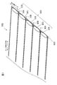
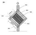
- FIG. 9 shows a schematic view of the picture frame method by the two-sided gripping method.
- One or a plurality of carbon fiber tape materials 900 having a length of 220 mm are arranged in parallel without gaps, and are prepared so that the sum of the total widths is 150 mm.
- the carbon fiber tape material 900 is used, the grip portion 902 is 200 mm, the measurement angle ⁇ [°] is 90 °, and the longitudinal direction of the carbon fiber tape is the picture plate.
- the carbon fiber tape material of the frame is attached to the picture frame jig 904 so as to grip the two sides of both ends of the carbon fiber tape so as to be parallel to the two sides 903 that do not hold the material.
- a universal testing machine (not shown) so that the measurement angle ⁇ [°] is 90 °
- pull the picture frame jig in the vertical direction at a speed of 50 mm / min and the tensile force F [at that time. N] and the measurement angle ⁇ are measured.
- the shear angle ⁇ [°] calculated from the following equation and ⁇ F / ⁇ in which ⁇ [°] is between 0.1 ° and 1.0 ° are calculated.
- FIG. 10 shows an example of a shear angle-tensile load graph when the picture frame method by the two-side gripping method is performed on the carbon fiber tape material according to the present invention.
- FIG. 10 (a) is a shear angle-tensile load graph when the shear angle ⁇ [°] is tested from 0 to 45
- FIG. 10 (b) shows a shear angle ⁇ [°] of the same graph from 0 to 1. It is a graph which enlarged the neighborhood.
- the shear load F is between 0 ° and 1.0 °.
- the maximum value of the tensile load F [N] is between 0 ° and 1.0 ° in shear angle ⁇ [°]
- the carbon fiber tape material reaches 1.0 ° in shear angle ⁇ [°]. It means that it has collapsed without being able to retain its morphology. In this case, the value of ⁇ F / ⁇ cannot be evaluated as the shear deformation performance of the carbon fiber tape material.
- the shear angle ⁇ [°] when the shear angle ⁇ [°] is between 0 ° and 1.0 ° and the tensile load F does not have the maximum value, the shear angle ⁇ [°] is from 0.1 °.
- ⁇ F / ⁇ between 1.0 ° is preferably less than 1.0, more preferably less than 0.4, and even more preferably less than 0.2.
- ⁇ F / ⁇ is 1.0 or more, a large force is required when the carbon fiber tape material is sheared and deformed, and good followability to the mold is obtained when the carbon fiber tape material is aligned and arranged in the mold by the fiber placement method. Cannot be obtained.
- ⁇ F / ⁇ is preferably larger than 0.1. When ⁇ F / ⁇ is 0.1 or less, the carbon fiber tape material undergoes large shear deformation by applying a slight force, and the stability of the carbon fiber tape material is impaired.
- the carbon fiber tape material according to the present invention preferably has a maximum tensile load F of more than 0.5 N and more than 1.0 N when tested with a shear angle ⁇ [°] of 0 ° to 45 °. Is even more preferable.
- the maximum value of the tensile load F is 0.5 N or less when the shear angle ⁇ [°] is set to 0 ° to 45 °, the carbon fiber tape material is a tape such that the carbon fiber bundle and the cloth material are peeled off. The morphology cannot be maintained.
- the fabric 1103 is arranged on both sides of the carbon fiber bundle group 1102, and when viewed as a whole, it is a tubular body. (FIG. 11 (a)) or a bag-like body (FIG. 11 (b)) is preferably formed. That is, as shown in FIG. 11A, the two carbon fiber bundles 1101 (a) and 1101 (b) located at both ends in the direction orthogonal to the fiber orientation direction of the carbon fiber bundle 1101 are the fabric 1103 on both sides thereof.
- the carbon fiber bundles 1101 (a) and 1101 (b) at both ends are bondable to form a tubular closed system with the fabrics 1103 on both sides. By doing so, it is possible to prevent the inner three carbon fiber bundles 1101 (c), 1101 (d), and 1101 (e) from falling off. Further, for the same reason, it is also preferable to arrange the fabric 1103 so as to include all the carbon fiber bundles 1101 as shown in FIG. 11 (b). By arranging the fabric on both sides of the carbon fiber bundle group in this way, it is possible to prevent the carbon fiber bundle from being detached during the handling of the carbon fiber tape material, and it is possible to improve the production stability of the carbon fiber tape material. it can.
- the carbon fiber tape material of the present invention is used for a reinforcing fiber laminate.
- the reinforcing fiber laminate is one in which the shape is maintained by arranging and laminating the carbon fiber tape material of the present invention and fixing at least a part between the layers. With such a configuration, the gaps between the carbon fiber bundles constituting the reinforcing fiber laminate can be set at an arbitrary distance and arranged. As a result, the fluidity of the matrix resin at the time of molding can be ensured, the type of resin to be injected and the width of the process window can be widened, and the productivity can be improved.
- the reinforcing fiber laminate using the carbon fiber tape material is impregnated with a matrix resin to form a fiber reinforced resin molded product.
- the obtained fiber-reinforced resin molded product can be completely impregnated with the resin to the inside and have high mechanical properties.
- Example 1 ⁇ Reinforcing fiber bundle>
- carbon fiber "Trading Card” registered trademark
- the elongation rate of the fabric was measured as follows with reference to JIS L 1096 8.16.1. That is, the fabric was cut into a width of 50 mm and a length of 300 mm so that the wale direction was the longitudinal direction, and the grip portion was marked so that the grip interval was 200 mm. After fixing one end of the test piece with a clamp, a load of 80 mN / 50 mm was gently applied, and the length between the marks after holding for 1 minute was measured. As a result of calculating the fabric elongation rate from the following formula, the elongation rate was 52%.
- a knitted fabric having a softening point temperature of 200 ° C. is placed on one side thereof, and the knitted fabric is heated at 120 ° C. to melt the binder particles.
- the ground and the carbon fiber bundle are partially bonded via the binder particles as shown in FIG. 4 (b).
- the binder particles are arranged in a staggered pattern as a sphere having a diameter of 4.5 mm, and both ends. Binder particles were arranged on the entire surface of the two carbon fiber bundles) and integrated. By doing so, a carbon fiber tape material having a width of 50 mm, a tape weight of 206 g / m 2 excluding the fabric, and a gap of 0.2 mm between the carbon fiber bundles was obtained.
- ⁇ Deformability of carbon fiber tape material As an evaluation of the deformability of the carbon fiber tape material, a picture frame method by a two-sided gripping method was carried out. Three carbon fiber tape materials having a length of 220 mm and a width of 50 mm were arranged in parallel, and the grip portions were marked so that the grip interval was 200 mm. Then, the three carbon fiber tape materials arranged in parallel are attached to the picture frame jig shown in FIG. 9 so as to grip the two sides so that the grip portion is 200 mm and the measurement angle ⁇ [°] is 90 °. The measurement was carried out.
- the carbon fiber tape material obtained as described above is pulled in one direction on the gantry so as to provide a gap of 0.7 mm between the carbon fiber tape materials.
- the sheet base material was produced by arranging them in an aligned manner and repeating the arrangement while cutting the carbon fiber tape material so as to have a square shape of 300 mm ⁇ 300 mm.
- Adjacent carbon fiber tape materials were made by wrapping adjacent knitted fabrics by 1 mm and heating the wrapped portion at 200 ° C. to bond and integrate them to form a sheet base material.
- the obtained sheet base material is placed in a pyramid (tetrahedron) shaped mold (bottom surface: an equilateral triangle with a side of 14 cm, height: 7 cm), and the upper mold is lowered and pressed while applying tension to the sheet base material. After shaping, the lower mold was heated at 120 ° C. for 10 minutes. As a result, the sheet base material showed good shapeability without large wrinkles.
- the sheet base material was sequentially shaped into a pyramid-shaped mold layer by layer in the same procedure, and then the upper mold was closed and then the lower mold was heated at 120 ° C. for 10 minutes. As a result, a good reinforcing fiber laminate was obtained without large wrinkles.
- ⁇ Molded body> The obtained reinforcing fiber laminate was placed in the above-mentioned pyramid-shaped lower mold, vacuum-bagged using a bag film, and then the mold was placed in an oven having an ambient temperature of 100 ° C. Then, a matrix resin (epoxy resin) was injected and cured in an atmosphere of 180 ° C. As a result, a good molded product having no resin-impregnated portion was obtained.
- a matrix resin epoxy resin
- Example 2 A carbon fiber tape was obtained in the same manner as in Example 1 except for the following points. -As the fabric, a knitted fabric having regularity (material: polyamide, basis weight: 10 g / m 2 ), which was warped in a chain + half structure using a tricot machine, was used.
- Example 3 A carbon fiber tape was obtained in the same manner as in Example 1 except for the following points. -After obtaining a carbon fiber bundle having a thread width of 3.5 mm with a fixed shape by the same method as in Example 1, 10 carbon fiber bundles are aligned in parallel in the longitudinal direction, and each of the carbon fiber bundles is aligned. The gap was adjusted to about 0.3 mm so that the width of the finally obtained carbon fiber tape material was 38 mm, and the tape texture excluding the fabric was 271 g / m 2 . -The knitted fabric and the carbon fiber bundle were integrated by partially adhering (the binder particles were arranged in a staggered pattern as a sphere having a diameter of 4.5 mm) as shown in FIG. 4A via the binder particles.
- Example 4 A carbon fiber tape was obtained in the same manner as in Example 1 except for the following points. -After obtaining a carbon fiber bundle having a thread width of 7.0 mm with a fixed shape by the same method as in Example 1, five carbon fiber bundles are aligned in parallel in the longitudinal direction, and each of the carbon fiber bundles is aligned. The gap was adjusted to about 0.7 mm so that the width of the finally obtained carbon fiber tape material was 38 mm, and the tape texture excluding the fabric was 135 g / m 2 . -The knitted fabric and the carbon fiber bundle are partially adhered to each other via the binder particles in the direction orthogonal to the fiber orientation of the carbon fiber bundle as shown in FIG. 7 (a) (each carbon fiber bundle (width 7 mm). Of these, 5 mm wide from the center was continuously bonded in the longitudinal direction) and integrated.
- Example 5 A carbon fiber tape was obtained in the same manner as in Example 1 except for the following points. -As the fabric, a non-woven fabric manufactured by Spunfab (material: polyamide, basis weight: 6 g / m 2 ) was used. -After obtaining a carbon fiber bundle having a thread width of 3.5 mm with a fixed shape by the same method as in Example 1, 10 carbon fiber bundles are aligned in parallel in the longitudinal direction, and each of the carbon fiber bundles is aligned. The gap was adjusted to 0.3 mm so that the width of the final carbon fiber tape material was 38 mm and the tape texture excluding the fabric was 271 g / m 2. ⁇ The non-woven fabric and the carbon fiber bundle are binder particles. As shown in FIG. 4A, the binder particles were partially bonded (arranged in a staggered pattern as a sphere having a diameter of 4.5 mm) and integrated.
- Example 1 A carbon fiber tape was obtained in the same manner as in Example 1 except for the following points.
- a non-woven fabric manufactured by Spunfab material: polyamide, softening point temperature: 130 ° C., basis weight: 10 g / m 2
- a non-woven fabric having a softening point temperature of 130 ° C. is placed on one side thereof and heated at 130 ° C. to melt the non-woven fabric. Then, the non-woven fabric and the carbon fiber bundle were completely adhered and integrated.
- a carbon fiber tape material having a width of 50 mm, a tape basis weight excluding the fabric of 206 g / m 2 , and a gap between the carbon fiber bundles of 0.2 mm was obtained.
- the molded product obtained by using the reinforcing fiber laminate is particularly suitable for aircraft, automobiles, ships and the like. It is also suitably used for large-sized members and members for general industrial use such as wind turbine blades.
Abstract
Description
(1)複数の炭素繊維束を繊維配向方向と平行に並べた炭素繊維束群と布地とを一体化させた炭素繊維テープ材料であって、次の(a)~(c)を満たすことを特徴とする炭素繊維テープ材料。
(a)前記布地が1または複数種類の熱可塑性樹脂から構成されている
(b)前記炭素繊維テープ材料のうち、布地を除いた目付が120g/m2~400g/m2の間にある
(c)前記布地の少なくとも一方向において、前記布地に80mN/50mmの荷重をかけた際の布地伸び率Ep(%)が5%~100%である
Ep=[(L1-L0)/L0]×100
Ep:布地伸び率(%)
L0:元の印間の布地長さ(mm)
L1:荷重付与時の布地長さ(mm)
(2)前記布地が規則性を有することを特徴とする、前記(1)に記載の炭素繊維テープ材料。
(3)炭素繊維束間に0.1mm~1mmの隙間が設けられていることを特徴とする、前記(1)または(2)に記載の炭素繊維テープ材料。
(4)前記炭素繊維テープ材料のテープ幅が、2mm~2000mmであることを特徴とする、前記(1)~(3)のいずれかに記載の炭素繊維テープ材料。
(5)前記炭素繊維束群と前記布地とが、前記炭素繊維束群の少なくとも片面に付着している樹脂バインダを介して、接着により一体化していることを特徴とする、前記(1)~(4)のいずれかに記載の炭素繊維テープ材料。
(6)前記樹脂バインダを介して前記布地と前記炭素繊維束群とを接着させた接着領域が、前記炭素繊維テープ材料の少なくとも一部において、前記炭素繊維束の繊維配向方向に離散的に形成されていることを特徴とする、前記(5)に記載の炭素繊維テープ材料。
(7)前記樹脂バインダを介して前記布地と前記炭素繊維束群とを接着させた接着領域が、前記炭素繊維テープ材料の全域において、前記炭素繊維束の繊維配向方向に離散的に形成されていることを特徴とする、前記(6)に記載の炭素繊維テープ材料。
(8)前記炭素繊維束群のうち、前記炭素繊維束の繊維配向方向と直交する方向の両端に位置する2本の炭素繊維束は、前記炭素繊維束の繊維配向方向に連続的に前記布地と接着されており、2本の炭素繊維束の間に位置する他の炭素繊維束は、前記炭素繊維束の繊維配向方向に間欠的に前記布地と接着されていることを特徴とする、前記(6)に記載の炭素繊維テープ材料。
(9)前記樹脂バインダを介して前記布地と前記炭素繊維束群とを接着させた接着領域のうち、隣り合う前記炭素繊維束においては、前記接着領域が、前記炭素繊維の繊維配向方向にずれていることを特徴とする、前記(6)~(8)のいずれかに記載の炭素繊維テープ材料。
(10)前記樹脂バインダを介して前記布地と前記炭素繊維束群とを接着させた接着領域が、前記炭素繊維テープ材料の少なくとも一部において、前記炭素繊維束の繊維配向に直交する方向に離散的に形成されてなることを特徴とする、前記(5)に記載の炭素繊維テープ材料。
(11)2辺把持法によるピクチャーフレーム法を用いてせん断角θ[°]を0°から45°の範囲で測定した引張荷重F[N]が、せん断角θ[°]が0°から1.0°の間で引張荷重F[N]の最大値を持たず、せん断角θ[°]を0°から45°の範囲で測定した引張荷重F[N]の最大値が0.5[N]より大きく、かつ、θ[°]が0.1°から1.0°の間において、ΔF/Δθが0.1より大きく1.0より小さいことを特徴とする、前記(1)~(10)のいずれかに記載の炭素繊維テープ材料。
(12)前記布地の形態が筒状体または袋状体であることを特徴とする、前記(1)~(11)に記載の炭素繊維テープ材料。
(13)前記(1)~(12)のいずれかに記載の炭素繊維テープ材料を用いてなる強化繊維積層体。
(14)前記(13)に記載の強化繊維積層体を用いてなる成形体。 The present invention has been made to solve at least a part of the above-mentioned problems, and is characterized by any of the following configurations.
(1) A carbon fiber tape material in which a group of carbon fiber bundles in which a plurality of carbon fiber bundles are arranged parallel to the fiber orientation direction and a fabric are integrated, and satisfying the following (a) to (c). Characterized carbon fiber tape material.
(A) The fabric is composed of one or a plurality of types of thermoplastic resins. (B) Of the carbon fiber tape materials, the texture excluding the fabric is between 120 g / m 2 and 400 g / m 2. c) In at least one direction of the fabric, the fabric elongation rate E p (%) when a load of 80 mN / 50 mm is applied to the fabric is 5% to 100% E p = [(L 1- L 0 ). / L 0 ] x 100
E p : Fabric elongation rate (%)
L 0 : Fabric length between the original marks (mm)
L 1 : Fabric length (mm) when a load is applied
(2) The carbon fiber tape material according to (1) above, wherein the fabric has regularity.
(3) The carbon fiber tape material according to (1) or (2) above, wherein a gap of 0.1 mm to 1 mm is provided between the carbon fiber bundles.
(4) The carbon fiber tape material according to any one of (1) to (3) above, wherein the tape width of the carbon fiber tape material is 2 mm to 2000 mm.
(5) The above (1) to the above, wherein the carbon fiber bundle group and the fabric are integrated by adhesion via a resin binder attached to at least one side of the carbon fiber bundle group. The carbon fiber tape material according to any one of (4).
(6) Adhesive regions in which the fabric and the carbon fiber bundle group are bonded via the resin binder are formed discretely in the fiber orientation direction of the carbon fiber bundle in at least a part of the carbon fiber tape material. The carbon fiber tape material according to (5) above, which is characterized by being made of.
(7) Adhesive regions in which the fabric and the carbon fiber bundle group are bonded via the resin binder are formed discretely in the fiber orientation direction of the carbon fiber bundle over the entire area of the carbon fiber tape material. The carbon fiber tape material according to (6) above, which is characterized by the above.
(8) Of the carbon fiber bundle group, the two carbon fiber bundles located at both ends in the direction orthogonal to the fiber orientation direction of the carbon fiber bundle are the fabric continuously in the fiber orientation direction of the carbon fiber bundle. The other carbon fiber bundles located between the two carbon fiber bundles are intermittently adhered to the fabric in the fiber orientation direction of the carbon fiber bundles (6). ) The carbon fiber tape material.
(9) Of the bonding regions in which the fabric and the carbon fiber bundle group are bonded via the resin binder, in the adjacent carbon fiber bundles, the bonding region is displaced in the fiber orientation direction of the carbon fibers. The carbon fiber tape material according to any one of (6) to (8) above, which is characterized by the above.
(10) The adhesive region in which the fabric and the carbon fiber bundle group are bonded via the resin binder is dispersed in at least a part of the carbon fiber tape material in a direction orthogonal to the fiber orientation of the carbon fiber bundle. The carbon fiber tape material according to (5) above, which is characterized in that it is formed in a plastic manner.
(11) The tensile load F [N] measured at a shear angle θ [°] in the range of 0 ° to 45 ° using the picture frame method based on the two-sided gripping method has a shear angle θ [°] of 0 ° to 1. The maximum value of the tensile load F [N] is 0.5 [N] when the shear angle θ [°] is measured in the range of 0 ° to 45 ° without having the maximum value of the tensile load F [N] between 0.0 °. N] and when θ [°] is between 0.1 ° and 1.0 °, ΔF / Δθ is larger than 0.1 and smaller than 1.0. The carbon fiber tape material according to any one of (10).
(12) The carbon fiber tape material according to (1) to (11) above, wherein the fabric is in the form of a tubular body or a bag-like body.
(13) A reinforcing fiber laminate using the carbon fiber tape material according to any one of (1) to (12) above.
(14) A molded product using the reinforcing fiber laminate according to (13) above.
Ep:布地伸び率(%)
L0:元の印間の布地長さ(mm)
L1:荷重付与時の布地長さ(mm)
布地伸び率の測定方法を図8に示す。図8(a)は一定荷重を負荷する前の布地803の状態を表す。指定のサイズに布地をカットし、指定の印808を布地にマーキングし、印間距離L0を測定後、図8(a)に示すようにクランプ807により布地をチャッキングする。その後、荷重を付与する。図8(b)は一定荷重付与後の布地803の状態を表す。図8(b)に示すように、一定荷重付与後の印間距離L1を測定することで、指定の式より伸び率を算出可能となる。なお、炭素繊維束と布地とを一体化したテープ材料から布地の伸び率を測定する場合は、布地をテープ材料から剥がしたのちに、上記手順で測定する。 E p = [(L 1- L 0 ) / L 0 ] x 100
E p : Fabric elongation rate (%)
L 0 : Fabric length between the original marks (mm)
L 1 : Fabric length (mm) when a load is applied
FIG. 8 shows a method for measuring the fabric elongation rate. FIG. 8A shows the state of the
樹脂バインダ204は、粒子形状でもよく、不織布形状でもよい。またこれらの形状に限定されるものではなく、フィルム、メッシュ、エマルジョン、コーティング、または炭素繊維束に巻きつける補助糸でも良い。 The carbon
本発明に係る炭素繊維テープ材料について2辺把持法によるピクチャーフレーム法を実施した時のせん断角―引張荷重グラフの一例を図10に示す。図10(a)はせん断角θ[°]を0から45まで試験した際のせん断角―引張荷重グラフであり、図10(b)は同一グラフのせん断角θ[°]が0から1の近傍を拡大したグラフである。 θ [°] = 90 ° ―α [°]
FIG. 10 shows an example of a shear angle-tensile load graph when the picture frame method by the two-side gripping method is performed on the carbon fiber tape material according to the present invention. FIG. 10 (a) is a shear angle-tensile load graph when the shear angle θ [°] is tested from 0 to 45, and FIG. 10 (b) shows a shear angle θ [°] of the same graph from 0 to 1. It is a graph which enlarged the neighborhood.
<強化繊維束>
強化繊維束として、予めサイジング処理を施した、東レ株式会社製炭素繊維「トレカ」(登録商標)T800SC、炭素繊維フィラメント数が24,000本(N=24K)を用いた。 (Example 1)
<Reinforcing fiber bundle>
As the reinforcing fiber bundle, carbon fiber "Trading Card" (registered trademark) T800SC manufactured by Toray Industries, Inc., which had been subjected to a sizing treatment in advance, and 24,000 carbon fiber filaments (N = 24K) were used.
布地として、トリコット機を用いてチュール組織状に経編した、規則性を有する編地(材質:ポリアミド、目付:8g/m2)を用いた。 <Fabric>
As the fabric, a regular knitted fabric (material: polyamide, basis weight: 8 g / m 2 ), which was warped in a tulle structure using a tricot machine, was used.
布地の伸び率は、JIS L 1096 8.16.1を参考に、以下のとおり測定した。すなわち、前記布地のウェール方向が長手方向となるように幅50mm、長さ300mmにカットし、つかみ間隔が200mmとなるようにつかみ部に印をつけた。試験片の一端をクランプで固定したのち、80mN/50mmの荷重を静かに付与して1分間保持後の印間の長さを測定した。次の式から布地伸び率を算出した結果、伸び率は52%となった。 <Measurement of fabric elongation>
The elongation rate of the fabric was measured as follows with reference to JIS L 1096 8.16.1. That is, the fabric was cut into a width of 50 mm and a length of 300 mm so that the wale direction was the longitudinal direction, and the grip portion was marked so that the grip interval was 200 mm. After fixing one end of the test piece with a clamp, a load of 80 mN / 50 mm was gently applied, and the length between the marks after holding for 1 minute was measured. As a result of calculating the fabric elongation rate from the following formula, the elongation rate was 52%.
Ep:布地伸び率(%)
L0:元の印間の布地長さ(mm)
L1:荷重付与時の布地長さ(mm)
<炭素繊維テープ材料>
図示しない炭素繊維束製造装置を用いて、炭素繊維束1本をボビンから引き出して、厚みを調整しながらスリットせずに幅を狭め、その後、軟化点温度80℃の加熱溶融性のバインダ粒子(平均粒径:0.2mm)を炭素繊維束の表面に散布した。バインダ粒子の重量割合は、5%(得られた炭素繊維束の重量を100%とする)となるように散布した後、溶融、冷却することで、その形態が固定された糸幅4.8mmの炭素繊維束を得た。 E p = [(L 1- L 0 ) / L 0 ] x 100
E p : Fabric elongation rate (%)
L 0 : Fabric length between the original marks (mm)
L 1 : Fabric length (mm) when a load is applied
<Carbon fiber tape material>
Using a carbon fiber bundle manufacturing device (not shown), one carbon fiber bundle is pulled out from the bobbin, the width is narrowed without slitting while adjusting the thickness, and then the heat-meltable binder particles having a softening point temperature of 80 ° C. ( Average particle size: 0.2 mm) was sprayed on the surface of the carbon fiber bundle. The weight ratio of the binder particles is 5% (the weight of the obtained carbon fiber bundle is 100%), and then melted and cooled to fix the yarn width of 4.8 mm. Carbon fiber bundle was obtained.
炭素繊維テープ材料の変形性評価として、2辺把持法によるピクチャーフレーム法を実施した。長さ220mm、幅50mmの炭素繊維テープ材料を3本平行に並べ、つかみ間隔が200mmとなるようにつかみ部に印をつけた。そして、3本平行に並べた炭素繊維テープ材料を、つかみ部が200mm、測定角α[°]が90°となるように、図9に示すピクチャーフレーム治具に2辺を把持するように取り付けて測定を実施した。その結果、せん断角θ[°]が0°から45°の範囲における引張荷重F[N]は、最大値が0.5[N]より大きく、また、該最大値は、せん断角θ[°]が0°から1.0°の間には存在しなかった。そして、ΔF/Δθ=0.3となり、炭素繊維テープ材料が面内のせん断の力に対し良好な変形性を示すことを確認した。 <Deformability of carbon fiber tape material>
As an evaluation of the deformability of the carbon fiber tape material, a picture frame method by a two-sided gripping method was carried out. Three carbon fiber tape materials having a length of 220 mm and a width of 50 mm were arranged in parallel, and the grip portions were marked so that the grip interval was 200 mm. Then, the three carbon fiber tape materials arranged in parallel are attached to the picture frame jig shown in FIG. 9 so as to grip the two sides so that the grip portion is 200 mm and the measurement angle α [°] is 90 °. The measurement was carried out. As a result, the maximum value of the tensile load F [N] in the range where the shear angle θ [°] is in the range of 0 ° to 45 ° is larger than 0.5 [N], and the maximum value is the shear angle θ [°]. ] Was not present between 0 ° and 1.0 °. Then, ΔF / Δθ = 0.3, and it was confirmed that the carbon fiber tape material showed good deformability with respect to the in-plane shearing force.
図示しないファイバープレイスメント装置を用いて、架台上に、上記のようにして得られた炭素繊維テープ材料を、それぞれの炭素繊維テープ材料間にそれぞれ0.7mmの隙間を設けるように一方向に引き揃えて配置し、300mm×300mmの正方形形状となるように炭素繊維テープ材料を切断しながら配置を繰り返してシート基材を製作した。隣り合う炭素繊維テープ材料は、隣り合う編地を1mmラップさせて、ラップ部を200℃で加熱することにより接着一体化してシート基材を製作した。 <Reinforcing fiber laminate>
Using a fiber placement device (not shown), the carbon fiber tape material obtained as described above is pulled in one direction on the gantry so as to provide a gap of 0.7 mm between the carbon fiber tape materials. The sheet base material was produced by arranging them in an aligned manner and repeating the arrangement while cutting the carbon fiber tape material so as to have a square shape of 300 mm × 300 mm. Adjacent carbon fiber tape materials were made by wrapping adjacent knitted fabrics by 1 mm and heating the wrapped portion at 200 ° C. to bond and integrate them to form a sheet base material.
得られた強化繊維積層体を前述のピラミッド形状の下型に配置し、バグフィルムを用いて真空バッグした後、雰囲気温度100℃のオーブン内に型を配置した。その後、マトリックス樹脂(エポキシ樹脂)を注入し、180℃雰囲気下で硬化した。その結果、樹脂未含浸部位のない良好な成形体が得られた。 <Molded body>
The obtained reinforcing fiber laminate was placed in the above-mentioned pyramid-shaped lower mold, vacuum-bagged using a bag film, and then the mold was placed in an oven having an ambient temperature of 100 ° C. Then, a matrix resin (epoxy resin) was injected and cured in an atmosphere of 180 ° C. As a result, a good molded product having no resin-impregnated portion was obtained.
以下の点以外は実施例1と同様にして炭素繊維テープを得た。
・布地として、トリコット機を用いて鎖+ハーフ組織状に経編した、規則性を有する編地(材質:ポリアミド、目付:10g/m2)を用いた。 (Example 2)
A carbon fiber tape was obtained in the same manner as in Example 1 except for the following points.
-As the fabric, a knitted fabric having regularity (material: polyamide, basis weight: 10 g / m 2 ), which was warped in a chain + half structure using a tricot machine, was used.
実施例1と同様の方法で伸び率を測定した結果、ウェール方向の伸び率は35%となった。 <Measurement of fabric elongation>
As a result of measuring the elongation rate by the same method as in Example 1, the elongation rate in the wale direction was 35%.
実施例1と同様の方法で2辺把持法によるピクチャーフレーム法を実施した結果、せん断角θ[°]が0°から45°の範囲における引張荷重F[N]は、最大値が0.5[N]より大きく、また、該最大値は、せん断角θ[°]が0°から1.0°の間には存在しなかった。そして、ΔF/Δθ=0.37となり、炭素繊維テープ材料が面内のせん断の力に対し良好な変形性を示すことを確認した。 <Deformability of carbon fiber tape material>
As a result of carrying out the picture frame method by the two-sided gripping method in the same manner as in Example 1, the maximum value of the tensile load F [N] in the range of the shear angle θ [°] from 0 ° to 45 ° is 0.5. It was larger than [N], and the maximum value was not present when the shear angle θ [°] was between 0 ° and 1.0 °. Then, ΔF / Δθ = 0.37, and it was confirmed that the carbon fiber tape material showed good deformability with respect to the in-plane shearing force.
実施例1と同様の方法で実施した結果、シート基材はよれやしわが生じることなく良好な強化繊維積層体が得られた。
<成形体>
実施例1と同様の方法で実施した結果、樹脂未含浸部位のない良好な成形体が得られた。 <Reinforcing fiber laminate>
As a result of carrying out in the same manner as in Example 1, a good reinforcing fiber laminate was obtained as the sheet base material without causing wrinkles or wrinkles.
<Molded body>
As a result of carrying out in the same manner as in Example 1, a good molded product having no resin-impregnated portion was obtained.
以下の点以外は実施例1と同様にして炭素繊維テープを得た。
・実施例1と同様の方法で、形態が固定された糸幅3.5mmの炭素繊維束を得た後、10本の炭素繊維束を長手方向に平行に引き揃え、炭素繊維束間の各隙間をおよそ0.3mmと調整し、最終的に得られる炭素繊維テープ材料における幅が38mm、布地を除いたテープ目付が271g/m2となるようにした。
・編地と炭素繊維束とは、バインダ粒子を介して図4(a)のように部分接着(バインダ粒子を直径4.5mmの球状体として千鳥状に配置)して一体化させた。 (Example 3)
A carbon fiber tape was obtained in the same manner as in Example 1 except for the following points.
-After obtaining a carbon fiber bundle having a thread width of 3.5 mm with a fixed shape by the same method as in Example 1, 10 carbon fiber bundles are aligned in parallel in the longitudinal direction, and each of the carbon fiber bundles is aligned. The gap was adjusted to about 0.3 mm so that the width of the finally obtained carbon fiber tape material was 38 mm, and the tape texture excluding the fabric was 271 g / m 2 .
-The knitted fabric and the carbon fiber bundle were integrated by partially adhering (the binder particles were arranged in a staggered pattern as a sphere having a diameter of 4.5 mm) as shown in FIG. 4A via the binder particles.
実施例1と同様の方法で2辺把持法によるピクチャーフレーム法を実施した結果、せん断角θ[°]が0°から45°の範囲における引張荷重F[N]は、最大値が0.5[N]より大きく、また、該最大値は、せん断角θ[°]が0°から1.0°の間には存在しなかった。そして、ΔF/Δθ=0.17となり、炭素繊維テープ材料が面内のせん断の力に対し良好な変形性を示すことを確認した。 <Deformability of carbon fiber tape material>
As a result of carrying out the picture frame method by the two-sided gripping method in the same manner as in Example 1, the maximum value of the tensile load F [N] in the range of the shear angle θ [°] from 0 ° to 45 ° is 0.5. It was larger than [N], and the maximum value was not present when the shear angle θ [°] was between 0 ° and 1.0 °. Then, ΔF / Δθ = 0.17, and it was confirmed that the carbon fiber tape material exhibited good deformability with respect to the in-plane shearing force.
実施例1と同様の方法で実施した結果、シート基材はよれやしわが生じることなく良好な強化繊維積層体が得られた。
<成形体>
実施例1と同様の方法で実施した結果、樹脂未含浸部位のない良好な成形体が得られた。 <Reinforcing fiber laminate>
As a result of carrying out in the same manner as in Example 1, a good reinforcing fiber laminate was obtained as the sheet base material without causing wrinkles or wrinkles.
<Molded body>
As a result of carrying out in the same manner as in Example 1, a good molded product having no resin-impregnated portion was obtained.
以下の点以外は実施例1と同様にして炭素繊維テープを得た。
・実施例1と同様の方法で、形態が固定された糸幅7.0mmの炭素繊維束を得た後、5本の炭素繊維束を長手方向に平行に引き揃え、炭素繊維束間の各隙間をおよそ0.7mmと調整し、最終的に得られる炭素繊維テープ材料における幅が38mm、布地を除いたテープ目付が135g/m2となるようにした。
・編地と炭素繊維束とは、バインダ粒子を介して、図7(a)のように炭素繊維束の繊維配向に直交する方向に離散的に部分接着(各炭素繊維束(幅7mm)のうち、中心から5mm幅分を長手方向に連続接着)して一体化させた。 (Example 4)
A carbon fiber tape was obtained in the same manner as in Example 1 except for the following points.
-After obtaining a carbon fiber bundle having a thread width of 7.0 mm with a fixed shape by the same method as in Example 1, five carbon fiber bundles are aligned in parallel in the longitudinal direction, and each of the carbon fiber bundles is aligned. The gap was adjusted to about 0.7 mm so that the width of the finally obtained carbon fiber tape material was 38 mm, and the tape texture excluding the fabric was 135 g / m 2 .
-The knitted fabric and the carbon fiber bundle are partially adhered to each other via the binder particles in the direction orthogonal to the fiber orientation of the carbon fiber bundle as shown in FIG. 7 (a) (each carbon fiber bundle (
実施例1と同様の方法で2辺把持法によるピクチャーフレーム法を実施した結果、せん断角θ[°]が0°から45°の範囲における引張荷重F[N]は、最大値が0.5[N]より大きく、また、該最大値は、せん断角θ[°]が0°から1.0°の間には存在しなかった。そして、ΔF/Δθ=0.33となり、炭素繊維テープ材料が面内のせん断の力に対し良好な変形性を示すことを確認した。 <Deformability of carbon fiber tape material>
As a result of carrying out the picture frame method by the two-sided gripping method in the same manner as in Example 1, the maximum value of the tensile load F [N] in the range of the shear angle θ [°] from 0 ° to 45 ° is 0.5. It was larger than [N], and the maximum value was not present when the shear angle θ [°] was between 0 ° and 1.0 °. Then, ΔF / Δθ = 0.33, and it was confirmed that the carbon fiber tape material showed good deformability with respect to the in-plane shearing force.
実施例1と同様の方法で実施した結果、シート基材はよれやしわが生じることなく良好な強化繊維積層体が得られた。 <Reinforcing fiber laminate>
As a result of carrying out in the same manner as in Example 1, a good reinforcing fiber laminate was obtained as the sheet base material without causing wrinkles or wrinkles.
実施例1と同様の方法で実施した結果、樹脂未含浸部位のない良好な成形体が得られた。 <Molded body>
As a result of carrying out in the same manner as in Example 1, a good molded product having no resin-impregnated portion was obtained.
以下の点以外は実施例1と同様にして炭素繊維テープを得た。
・布地として、Spunfab社製不織布(材質:ポリアミド、目付:6g/m2)を用いた。
・実施例1と同様の方法で、形態が固定された糸幅3.5mmの炭素繊維束を得た後、10本の炭素繊維束を長手方向に平行に引き揃え、炭素繊維束間の各隙間を0.3mmと調整し、最終的に得られる炭素繊維テープ材料における幅が38mm、布地を除いたテープ目付が271g/m2となるようにした
・不織布と炭素繊維束とは、バインダ粒子を介して図4(a)のように部分接着(バインダ粒子を直径4.5mmの球状体として千鳥状に配置)して一体化させた。 (Example 5)
A carbon fiber tape was obtained in the same manner as in Example 1 except for the following points.
-As the fabric, a non-woven fabric manufactured by Spunfab (material: polyamide, basis weight: 6 g / m 2 ) was used.
-After obtaining a carbon fiber bundle having a thread width of 3.5 mm with a fixed shape by the same method as in Example 1, 10 carbon fiber bundles are aligned in parallel in the longitudinal direction, and each of the carbon fiber bundles is aligned. The gap was adjusted to 0.3 mm so that the width of the final carbon fiber tape material was 38 mm and the tape texture excluding the fabric was 271 g / m 2.・ The non-woven fabric and the carbon fiber bundle are binder particles. As shown in FIG. 4A, the binder particles were partially bonded (arranged in a staggered pattern as a sphere having a diameter of 4.5 mm) and integrated.
実施例1と同様の方法で伸び率を測定した結果、ウェール方向の伸び率は10%となり、良好な変形性が得られた。 <Measurement of fabric elongation>
As a result of measuring the elongation rate by the same method as in Example 1, the elongation rate in the wale direction was 10%, and good deformability was obtained.
実施例1と同様の方法で2辺把持法によるピクチャーフレーム法を実施した結果、せん断角θ[°]が0°から45°の範囲における引張荷重F[N]は、最大値が0.5[N]より大きく、また、該最大値は、せん断角θ[°]が0°から1.0°の間には存在しなかった。そして、ΔF/Δθ=0.23となり、炭素繊維テープ材料が面内のせん断の力に対し良好な変形性を示すことを確認した。 <Deformability of carbon fiber tape material>
As a result of carrying out the picture frame method by the two-sided gripping method in the same manner as in Example 1, the maximum value of the tensile load F [N] in the range of the shear angle θ [°] from 0 ° to 45 ° is 0.5. It was larger than [N], and the maximum value was not present when the shear angle θ [°] was between 0 ° and 1.0 °. Then, ΔF / Δθ = 0.23, and it was confirmed that the carbon fiber tape material showed good deformability with respect to the in-plane shearing force.
実施例1と同様の方法で実施した結果、シート基材はよれやしわが生じることなく良好な強化繊維積層体が得られた。 <Reinforcing fiber laminate>
As a result of carrying out in the same manner as in Example 1, a good reinforcing fiber laminate was obtained as the sheet base material without causing wrinkles or wrinkles.
実施例1と同様の方法で実施した結果、樹脂未含浸部位のない良好な成形体が得られた。 <Molded body>
As a result of carrying out in the same manner as in Example 1, a good molded product having no resin-impregnated portion was obtained.
以下の点以外は実施例1と同様にして炭素繊維テープを得た。
・布地として、Spunfab社製不織布(材質:ポリアミド、軟化点温度:130℃、目付:10g/m2)を用いた。
・バインダ粒子の付着していない10本の炭素繊維束を長手方向に平行に引き揃えた後、その片面に軟化点温度130℃の不織布を配置し、130℃で加熱して不織布を溶融することで、不織布と炭素繊維束とを全面接着して一体化させた。このようにすることにより、幅が50mm、布地を除いたテープ目付が206g/m2、炭素繊維束間の各隙間が0.2mmの炭素繊維テープ材料を得た。 (Comparative Example 1)
A carbon fiber tape was obtained in the same manner as in Example 1 except for the following points.
-As the fabric, a non-woven fabric manufactured by Spunfab (material: polyamide, softening point temperature: 130 ° C., basis weight: 10 g / m 2 ) was used.
・ After aligning 10 carbon fiber bundles to which no binder particles are attached in parallel in the longitudinal direction, a non-woven fabric having a softening point temperature of 130 ° C. is placed on one side thereof and heated at 130 ° C. to melt the non-woven fabric. Then, the non-woven fabric and the carbon fiber bundle were completely adhered and integrated. By doing so, a carbon fiber tape material having a width of 50 mm, a tape basis weight excluding the fabric of 206 g / m 2 , and a gap between the carbon fiber bundles of 0.2 mm was obtained.
実施例1と同様の方法で伸び率を測定した結果、ウェール方向の伸び率は3%となり、良好な変形性は得られなかった。 <Measurement of fabric elongation>
As a result of measuring the elongation rate by the same method as in Example 1, the elongation rate in the wale direction was 3%, and good deformability was not obtained.
実施例1と同様の方法で2辺把持法によるピクチャーフレーム法を実施した結果、せん断角θ[°]が0°から45°の範囲における引張荷重F[N]は、最大値が0.5[N]より大きく、また、該最大値は、せん断角θ[°]が0°から1.0°の間には存在しなかった。そして、ΔF/Δθ=1.2となり、炭素繊維テープ材料が面内のせん断の力に対し良好な変形性を示さないことを確認した。 <Deformability of carbon fiber tape material>
As a result of carrying out the picture frame method by the two-sided gripping method in the same manner as in Example 1, the maximum value of the tensile load F [N] in the range of the shear angle θ [°] from 0 ° to 45 ° is 0.5. It was larger than [N], and the maximum value was not present when the shear angle θ [°] was between 0 ° and 1.0 °. Then, it was confirmed that ΔF / Δθ = 1.2 and the carbon fiber tape material did not show good deformability with respect to the in-plane shearing force.
実施例1と同様の方法で実施した結果、シート基材にはよれやしわが見られ、良好な強化繊維積層体が得られなかった。 <Reinforcing fiber laminate>
As a result of carrying out in the same manner as in Example 1, wrinkles and wrinkles were observed in the sheet base material, and a good reinforcing fiber laminate could not be obtained.
実施例1と同様の方法で実施した結果、しわの生じた箇所に樹脂未含浸部位のある成形体が得られた。 <Molded body>
As a result of carrying out in the same manner as in Example 1, a molded product having a resin-unimpregnated portion at the wrinkled portion was obtained.

101、201、301、401、501、601、1101 炭素繊維束
102、202、302、402、1102 炭素繊維束群
103、203、303、403、503、603、703、803、1103 布地
106、206、306 隙間
204、304、1104 樹脂バインダ
305、405、505、605、705、1105 接着領域
807 クランプ
808 印
902 つかみ部
903 炭素繊維テープ材料を把持していない2辺
904 ピクチャーフレーム治具 100, 200, 300, 400, 500, 900, 1100 carbon fiber tape material
101, 201, 301, 401, 501, 601, 1101
Claims (14)
- 複数の炭素繊維束を繊維配向方向と平行に並べた炭素繊維束群と布地とを一体化させた炭素繊維テープ材料であって、次の(a)~(c)を満たすことを特徴とする炭素繊維テープ材料。
(a)前記布地が1または複数種類の熱可塑性樹脂から構成されている
(b)前記炭素繊維テープ材料のうち、布地を除いた目付が120g/m2~400g/m2の間にある
(c)前記布地の少なくとも一方向において、前記布地に80mN/50mmの荷重をかけた際の布地伸び率Ep(%)が5%~100%である
Ep=[(L1-L0)/L0]×100
Ep:布地伸び率(%)
L0:元の印間の布地長さ(mm)
L1:荷重付与時の布地長さ(mm) It is a carbon fiber tape material in which a group of carbon fiber bundles in which a plurality of carbon fiber bundles are arranged in parallel with the fiber orientation direction and a fabric are integrated, and is characterized by satisfying the following (a) to (c). Carbon fiber tape material.
(A) The fabric is composed of one or a plurality of types of thermoplastic resins. (B) Of the carbon fiber tape materials, the texture excluding the fabric is between 120 g / m 2 and 400 g / m 2. c) In at least one direction of the fabric, the fabric elongation rate E p (%) when a load of 80 mN / 50 mm is applied to the fabric is 5% to 100% E p = [(L 1- L 0 ). / L 0 ] x 100
E p : Fabric elongation rate (%)
L 0 : Fabric length between the original marks (mm)
L 1 : Fabric length (mm) when a load is applied - 前記布地が規則性を有することを特徴とする、請求項1に記載の炭素繊維テープ材料。 The carbon fiber tape material according to claim 1, wherein the fabric has regularity.
- 炭素繊維束間に0.1mm~1mmの隙間が設けられていることを特徴とする、請求項1または2に記載の炭素繊維テープ材料。 The carbon fiber tape material according to claim 1 or 2, wherein a gap of 0.1 mm to 1 mm is provided between the carbon fiber bundles.
- 前記炭素繊維テープ材料のテープ幅が、2mm~2000mmであることを特徴とする、請求項1~3のいずれかに記載の炭素繊維テープ材料。 The carbon fiber tape material according to any one of claims 1 to 3, wherein the tape width of the carbon fiber tape material is 2 mm to 2000 mm.
- 前記炭素繊維束群と前記布地とが、前記炭素繊維束群の少なくとも片面に付着している樹脂バインダを介して、接着により一体化していることを特徴とする、請求項1~4のいずれかに記載の炭素繊維テープ材料。 Any of claims 1 to 4, wherein the carbon fiber bundle group and the fabric are integrated by adhesion via a resin binder attached to at least one side of the carbon fiber bundle group. The carbon fiber tape material described in.
- 前記樹脂バインダを介して前記布地と前記炭素繊維束群とを接着させた接着領域が、前記炭素繊維テープ材料の少なくとも一部において、前記炭素繊維束の繊維配向方向に離散的に形成されていることを特徴とする、請求項5に記載の炭素繊維テープ材料。 Adhesive regions in which the fabric and the carbon fiber bundle group are bonded via the resin binder are formed discretely in the fiber orientation direction of the carbon fiber bundle in at least a part of the carbon fiber tape material. The carbon fiber tape material according to claim 5, characterized in that.
- 前記樹脂バインダを介して前記布地と前記炭素繊維束群とを接着させた接着領域が、前記炭素繊維テープ材料の全域において、前記炭素繊維束の繊維配向方向に離散的に形成されていることを特徴とする、請求項6に記載の炭素繊維テープ材料。 The bonding region in which the fabric and the carbon fiber bundle group are bonded via the resin binder is formed discretely in the fiber orientation direction of the carbon fiber bundle over the entire area of the carbon fiber tape material. The carbon fiber tape material according to claim 6, which is characterized.
- 前記炭素繊維束群のうち、前記炭素繊維束の繊維配向方向と直交する方向の両端に位置する2本の炭素繊維束は、前記炭素繊維束の繊維配向方向に連続的に前記布地と接着されており、2本の炭素繊維束の間に位置する他の炭素繊維束は、前記炭素繊維束の繊維配向方向に間欠的に前記布地と接着されていることを特徴とする、請求項6に記載の炭素繊維テープ材料。 Of the carbon fiber bundle group, two carbon fiber bundles located at both ends in a direction orthogonal to the fiber orientation direction of the carbon fiber bundle are continuously adhered to the fabric in the fiber orientation direction of the carbon fiber bundle. The sixth aspect of claim 6, wherein the other carbon fiber bundles located between the two carbon fiber bundles are intermittently adhered to the fabric in the fiber orientation direction of the carbon fiber bundles. Carbon fiber tape material.
- 前記樹脂バインダを介して前記布地と前記炭素繊維束群とを接着させた接着領域のうち、隣り合う前記炭素繊維束においては、前記接着領域が、前記炭素繊維の繊維配向方向にずれていることを特徴とする、請求項6~8のいずれかに記載の炭素繊維テープ材料。 Among the bonding regions in which the fabric and the carbon fiber bundle group are bonded via the resin binder, in the adjacent carbon fiber bundles, the bonding region is displaced in the fiber orientation direction of the carbon fibers. The carbon fiber tape material according to any one of claims 6 to 8, wherein the carbon fiber tape material is characterized.
- 前記樹脂バインダを介して前記布地と前記炭素繊維束群とを接着させた接着領域が、前記炭素繊維テープ材料の少なくとも一部において、前記炭素繊維束の繊維配向に直交する方向に離散的に形成されてなることを特徴とする、請求項5に記載の炭素繊維テープ材料。 Adhesive regions in which the fabric and the carbon fiber bundle group are bonded via the resin binder are discretely formed in at least a part of the carbon fiber tape material in a direction orthogonal to the fiber orientation of the carbon fiber bundle. The carbon fiber tape material according to claim 5, wherein the carbon fiber tape material is made of.
- 2辺把持法によるピクチャーフレーム法を用いてせん断角θ[°]を0°から45°の範囲で測定した引張荷重F[N]が、せん断角θ[°]が0°から1.0°の間で引張荷重F[N]の最大値を持たず、せん断角θ[°]を0°から45°の範囲で測定した引張荷重F[N]の最大値が0.5[N]より大きく、かつ、θ[°]が0.1°から1.0°の間において、ΔF/Δθが0.1より大きく1.0より小さいことを特徴とする、請求項1~10のいずれかに記載の炭素繊維テープ材料。 The tensile load F [N] measured at a shear angle θ [°] in the range of 0 ° to 45 ° using the picture frame method based on the two-sided grip method has a shear angle θ [°] of 0 ° to 1.0 °. The maximum value of the tensile load F [N] is 0.5 [N] when the shear angle θ [°] is measured in the range of 0 ° to 45 ° without having the maximum value of the tensile load F [N]. Any of claims 1 to 10, characterized in that ΔF / Δθ is greater than 0.1 and less than 1.0 when θ [°] is between 0.1 ° and 1.0 °. The carbon fiber tape material described in.
- 前記布地の形態が筒状体または袋状体であることを特徴とする、請求項1~11に記載の炭素繊維テープ材料。 The carbon fiber tape material according to any one of claims 1 to 11, wherein the fabric is in the form of a tubular body or a bag-like body.
- 請求項1~12のいずれかに記載の炭素繊維テープ材料を用いてなる強化繊維積層体。 A reinforcing fiber laminate using the carbon fiber tape material according to any one of claims 1 to 12.
- 請求項13に記載の強化繊維積層体を用いてなる成形体。 A molded product using the reinforcing fiber laminate according to claim 13.
Priority Applications (5)
| Application Number | Priority Date | Filing Date | Title |
|---|---|---|---|
| US17/773,639 US20220379523A1 (en) | 2019-11-11 | 2020-11-05 | Carbon fiber tape material, and reinforcing fiber laminate and molded body produced with the same |
| JP2020564017A JPWO2021095623A1 (en) | 2019-11-11 | 2020-11-05 | |
| AU2020383077A AU2020383077A1 (en) | 2019-11-11 | 2020-11-05 | Carbon fiber tape material, and reinforced fiber laminate and molded article using same |
| EP20886404.1A EP4059685A4 (en) | 2019-11-11 | 2020-11-05 | Carbon fiber tape material, and reinforced fiber laminate and molded article using same |
| CN202080075938.3A CN114616090B (en) | 2019-11-11 | 2020-11-05 | Carbon fiber tape material, and reinforcing fiber laminate and molded body using same |
Applications Claiming Priority (4)
| Application Number | Priority Date | Filing Date | Title |
|---|---|---|---|
| JP2019203907 | 2019-11-11 | ||
| JP2019203908 | 2019-11-11 | ||
| JP2019-203908 | 2019-11-11 | ||
| JP2019-203907 | 2019-11-11 |
Publications (1)
| Publication Number | Publication Date |
|---|---|
| WO2021095623A1 true WO2021095623A1 (en) | 2021-05-20 |
Family
ID=75911486
Family Applications (1)
| Application Number | Title | Priority Date | Filing Date |
|---|---|---|---|
| PCT/JP2020/041312 WO2021095623A1 (en) | 2019-11-11 | 2020-11-05 | Carbon fiber tape material, and reinforced fiber laminate and molded article using same |
Country Status (7)
| Country | Link |
|---|---|
| US (1) | US20220379523A1 (en) |
| EP (1) | EP4059685A4 (en) |
| JP (1) | JPWO2021095623A1 (en) |
| CN (1) | CN114616090B (en) |
| AU (1) | AU2020383077A1 (en) |
| TW (1) | TW202124135A (en) |
| WO (1) | WO2021095623A1 (en) |
Citations (10)
| Publication number | Priority date | Publication date | Assignee | Title |
|---|---|---|---|---|
| JPH07149927A (en) * | 1993-12-02 | 1995-06-13 | Toray Ind Inc | Prepreg and its production |
| JP2010155460A (en) * | 1999-03-23 | 2010-07-15 | Toray Ind Inc | Compound carbon fiber base material, pre-form and method for manufacturing carbon-fiber reinforced plastic |
| WO2012011437A1 (en) * | 2010-07-23 | 2012-01-26 | 日産自動車株式会社 | Abnormal torque evaluation apparatus for electrically driven vehicle |
| JP2012510385A (en) | 2008-11-28 | 2012-05-10 | ヘクセル ランフォルセマン | A novel intermediate material with constant width for the production of composite parts by direct method |
| JP2015502271A (en) * | 2011-10-24 | 2015-01-22 | ハンファ アズデル インコーポレイテッド | Deep drawn composites and methods of using them |
| JP2015017343A (en) * | 2013-07-12 | 2015-01-29 | 株式会社クラレ | Fiber base material tape or sheet, manufacturing method thereof and fiber reinforced composite material |
| JP2015116806A (en) | 2013-11-15 | 2015-06-25 | 八田経編株式会社 | Sheet material for reinforcing thermoplastic resin, and manufacturing method thereof |
| JP2017521291A (en) | 2014-06-30 | 2017-08-03 | サイテック インダストリーズ インコーポレイテッド | Dry fiber tape for preform production |
| JP2018501121A (en) * | 2014-11-21 | 2018-01-18 | テープ、ウィービング、スウェーデン、アクチボラグTape Weaving Sweden Ab | Tape-like dry fiber reinforcement |
| WO2018052080A1 (en) * | 2016-09-14 | 2018-03-22 | 三菱ケミカル株式会社 | Layered substrate and method for manufacturing same |
Family Cites Families (8)
| Publication number | Priority date | Publication date | Assignee | Title |
|---|---|---|---|---|
| JP2791875B2 (en) * | 1996-01-31 | 1998-08-27 | 川崎重工業株式会社 | Highly impregnated three-dimensional fabric, carbon fiber reinforced composite material and ceramic composite material using the fabric |
| KR20010014068A (en) * | 1997-07-23 | 2001-02-26 | 사가라 아스히코 | Unidirectional reinforcing fiber composite substrate |
| JP2001064406A (en) * | 1999-08-31 | 2001-03-13 | Toray Ind Inc | Preform for fiber-reinforced preform and fiber- reinforced composite material using the same and production thereof |
| DE102010050079A1 (en) * | 2010-10-29 | 2012-05-03 | Premium Aerotec Gmbh | Partially fixed semi-finished textile |
| KR101931826B1 (en) * | 2010-12-24 | 2018-12-21 | 도레이 카부시키가이샤 | Method for producing carbon fiber aggregate, and method for producing carbon fiber-reinforced plastic |
| GB201417769D0 (en) * | 2014-10-08 | 2014-11-19 | Rolls Royce Plc | Composite article |
| EP3112111A1 (en) * | 2015-07-02 | 2017-01-04 | Honda Motor Co., Ltd. | A fiber tape for producing fiber reinforced parts and process for manufacturing such a fiber tape |
| CN108291044A (en) * | 2015-12-25 | 2018-07-17 | 东丽株式会社 | Prepreg and its manufacturing method |
-
2020
- 2020-11-05 JP JP2020564017A patent/JPWO2021095623A1/ja active Pending
- 2020-11-05 WO PCT/JP2020/041312 patent/WO2021095623A1/en unknown
- 2020-11-05 US US17/773,639 patent/US20220379523A1/en active Pending
- 2020-11-05 CN CN202080075938.3A patent/CN114616090B/en active Active
- 2020-11-05 AU AU2020383077A patent/AU2020383077A1/en active Pending
- 2020-11-05 EP EP20886404.1A patent/EP4059685A4/en active Pending
- 2020-11-09 TW TW109138968A patent/TW202124135A/en unknown
Patent Citations (10)
| Publication number | Priority date | Publication date | Assignee | Title |
|---|---|---|---|---|
| JPH07149927A (en) * | 1993-12-02 | 1995-06-13 | Toray Ind Inc | Prepreg and its production |
| JP2010155460A (en) * | 1999-03-23 | 2010-07-15 | Toray Ind Inc | Compound carbon fiber base material, pre-form and method for manufacturing carbon-fiber reinforced plastic |
| JP2012510385A (en) | 2008-11-28 | 2012-05-10 | ヘクセル ランフォルセマン | A novel intermediate material with constant width for the production of composite parts by direct method |
| WO2012011437A1 (en) * | 2010-07-23 | 2012-01-26 | 日産自動車株式会社 | Abnormal torque evaluation apparatus for electrically driven vehicle |
| JP2015502271A (en) * | 2011-10-24 | 2015-01-22 | ハンファ アズデル インコーポレイテッド | Deep drawn composites and methods of using them |
| JP2015017343A (en) * | 2013-07-12 | 2015-01-29 | 株式会社クラレ | Fiber base material tape or sheet, manufacturing method thereof and fiber reinforced composite material |
| JP2015116806A (en) | 2013-11-15 | 2015-06-25 | 八田経編株式会社 | Sheet material for reinforcing thermoplastic resin, and manufacturing method thereof |
| JP2017521291A (en) | 2014-06-30 | 2017-08-03 | サイテック インダストリーズ インコーポレイテッド | Dry fiber tape for preform production |
| JP2018501121A (en) * | 2014-11-21 | 2018-01-18 | テープ、ウィービング、スウェーデン、アクチボラグTape Weaving Sweden Ab | Tape-like dry fiber reinforcement |
| WO2018052080A1 (en) * | 2016-09-14 | 2018-03-22 | 三菱ケミカル株式会社 | Layered substrate and method for manufacturing same |
Non-Patent Citations (1)
| Title |
|---|
| See also references of EP4059685A4 |
Also Published As
| Publication number | Publication date |
|---|---|
| AU2020383077A1 (en) | 2022-06-09 |
| CN114616090B (en) | 2024-04-05 |
| EP4059685A1 (en) | 2022-09-21 |
| EP4059685A4 (en) | 2023-12-20 |
| JPWO2021095623A1 (en) | 2021-05-20 |
| US20220379523A1 (en) | 2022-12-01 |
| CN114616090A (en) | 2022-06-10 |
| TW202124135A (en) | 2021-07-01 |
Similar Documents
| Publication | Publication Date | Title |
|---|---|---|
| US11421089B2 (en) | Prepreg sheet, method for manufacturing same, unit layer with a covering material, method for manufacturing fiber-reinforced composite, and fiber-reinforced composite | |
| US9770844B2 (en) | Fibre reinforced composites | |
| KR101260088B1 (en) | Reinforcing woven fabric and process for producing the same | |
| JP5572947B2 (en) | Molding material, fiber reinforced plastic, and production method thereof | |
| JP6965957B2 (en) | Laminated base material, its manufacturing method, and carbon fiber reinforced resin base material | |
| JP2003136550A (en) | Method for manufacturing carbon fiber base material, method for manufacturing preform, and method for manufacturing composite material | |
| US20220040935A1 (en) | Method for manufacturing molded article of fiber-reinforced composite material, reinforcing fiber substrate and molded article of fiber-reinforced composite material | |
| JP2010214704A (en) | Base material for preform using binder including superfine fiber, and method of manufacturing the same | |
| JP7344472B2 (en) | Reinforced fiber tape material and its manufacturing method, reinforced fiber laminate and fiber reinforced resin molded product using reinforced fiber tape material | |
| WO2021095623A1 (en) | Carbon fiber tape material, and reinforced fiber laminate and molded article using same | |
| CA3008119C (en) | Reinforced fiber laminate sheet, fiber-reinforced resin molded body, and method for manufacturing reinforced fiber laminate sheet | |
| GB2508078A (en) | Non-woven moulding reinforcement material | |
| JP7467840B2 (en) | Reinforced fiber substrate, reinforced fiber laminate, and fiber reinforced resin | |
| JP2022137447A (en) | Carbon fiber tape material and reinforcing fiber laminate using the same, and molded body | |
| CN111699210B (en) | Dry tape material for fiber placement, method for producing same, and reinforced fiber laminate and fiber-reinforced resin molded body using same | |
| JP2022068616A (en) | Reinforced fiber base material for resin injection molding, reinforced fiber laminate for resin injection molding and fiber reinforced resin |
Legal Events
| Date | Code | Title | Description |
|---|---|---|---|
| ENP | Entry into the national phase |
Ref document number: 2020564017 Country of ref document: JP Kind code of ref document: A |
|
| 121 | Ep: the epo has been informed by wipo that ep was designated in this application |
Ref document number: 20886404 Country of ref document: EP Kind code of ref document: A1 |
|
| ENP | Entry into the national phase |
Ref document number: 2020383077 Country of ref document: AU Date of ref document: 20201105 Kind code of ref document: A |
|
| NENP | Non-entry into the national phase |
Ref country code: DE |
|
| ENP | Entry into the national phase |
Ref document number: 2020886404 Country of ref document: EP Effective date: 20220613 |