RU2610459C2 - One-piece joint for insulated conductors - Google Patents
One-piece joint for insulated conductors Download PDFInfo
- Publication number
- RU2610459C2 RU2610459C2 RU2014118477A RU2014118477A RU2610459C2 RU 2610459 C2 RU2610459 C2 RU 2610459C2 RU 2014118477 A RU2014118477 A RU 2014118477A RU 2014118477 A RU2014118477 A RU 2014118477A RU 2610459 C2 RU2610459 C2 RU 2610459C2
- Authority
- RU
- Russia
- Prior art keywords
- core
- section
- insulating layer
- heating
- formation
- Prior art date
Links
Images


Classifications
-
- E—FIXED CONSTRUCTIONS
- E21—EARTH DRILLING; MINING
- E21B—EARTH DRILLING, e.g. DEEP DRILLING; OBTAINING OIL, GAS, WATER, SOLUBLE OR MELTABLE MATERIALS OR A SLURRY OF MINERALS FROM WELLS
- E21B36/00—Heating, cooling, insulating arrangements for boreholes or wells, e.g. for use in permafrost zones
- E21B36/04—Heating, cooling, insulating arrangements for boreholes or wells, e.g. for use in permafrost zones using electrical heaters
-
- Y—GENERAL TAGGING OF NEW TECHNOLOGICAL DEVELOPMENTS; GENERAL TAGGING OF CROSS-SECTIONAL TECHNOLOGIES SPANNING OVER SEVERAL SECTIONS OF THE IPC; TECHNICAL SUBJECTS COVERED BY FORMER USPC CROSS-REFERENCE ART COLLECTIONS [XRACs] AND DIGESTS
- Y10—TECHNICAL SUBJECTS COVERED BY FORMER USPC
- Y10T—TECHNICAL SUBJECTS COVERED BY FORMER US CLASSIFICATION
- Y10T29/00—Metal working
- Y10T29/49—Method of mechanical manufacture
- Y10T29/49002—Electrical device making
- Y10T29/49117—Conductor or circuit manufacturing
- Y10T29/49194—Assembling elongated conductors, e.g., splicing, etc.
- Y10T29/49195—Assembling elongated conductors, e.g., splicing, etc. with end-to-end orienting
Abstract
Description
Область техники, к которой относится изобретениеFIELD OF THE INVENTION
Настоящее изобретение относится к системам для изолированных проводников, используемых в нагревательных элементах. Более конкретно, изобретение относится к соединительным элементам, предназначенным для стыковки изолированных кабелей и/или вводных кабелей.The present invention relates to systems for insulated conductors used in heating elements. More specifically, the invention relates to connecting elements for joining insulated cables and / or input cables.
Уровень техникиState of the art
Углеводороды, добываемые из подземных пластов, часто используют в качестве энергетических ресурсов, в качестве сырья и в качестве потребительских товаров. Обеспокоенность истощением доступных углеводородных ресурсов и обеспокоенность спадом общего качества производимых углеводородов привело к развитию процессов для более эффективной добычи, обработки и/или использования доступных углеводородных ресурсов. Процессы, выполняемые в пласте, могут быть использованы для извлечения углеводородных материалов из подземных пластов, которые ранее были недоступны, и/или извлечение их оттуда с использованием доступных способов было слишком дорогим. Может потребоваться изменение химических и/или физических свойств углеводородного материала в подземном пласте, чтобы позволить более просто изъять углеводородный материал из подземного пласта и/или увеличить ценность углеводородного материала. Химические и/или физические изменения могут включать в себя проходящие на месте реакции, которые производят извлекаемые текучие среды, изменения состава, изменения растворимости, изменения плотности, фазовые изменения и/или изменения вязкости углеводородного материала в пласте.Hydrocarbons extracted from underground formations are often used as energy resources, as raw materials and as consumer goods. Concerns over the depletion of available hydrocarbon resources and concern over the decline in the overall quality of hydrocarbons produced has led to the development of processes for more efficient production, processing and / or use of available hydrocarbon resources. The processes performed in the formation can be used to extract hydrocarbon materials from underground formations that were previously unavailable, and / or to extract them from there using available methods was too expensive. It may be necessary to change the chemical and / or physical properties of the hydrocarbon material in the subterranean formation in order to more easily remove the hydrocarbon material from the subterranean formation and / or increase the value of the hydrocarbon material. Chemical and / or physical changes may include in situ reactions that produce recoverable fluids, changes in composition, changes in solubility, changes in density, phase changes and / or changes in the viscosity of the hydrocarbon material in the formation.
В скважинах можно разместить нагреватели для нагрева пласта во время проходящего в пласте процесса. Существует много различных типов нагревателей, которые можно использовать для нагрева пласта. Примеры процессов в пласте, использующих скважинные нагреватели приведены в патентах США №№2634961, выданном Льюнгсторму; 2732195, выданном Льюнгсторму; 2780450, выданном Льюнгсторму; 2789805, выданном Льюнгсторму; 2923535, выданном Льюнгсторму; 4886118, выданном Ван Мерсу и др. и 6688387, выданном Веллингтону и др.In the wells, heaters can be placed to heat the formation during a process in the formation. There are many different types of heaters that can be used to heat the formation. Examples of formation processes using downhole heaters are given in US Pat. Nos. 2,634,961 issued to Ljungstorm; 2,732,195 issued to Ljungstorm; 2,780,450 issued to Ljungstorm; 2,789,805 issued to Ljungstorm; 2,923,535 issued to Ljungstorm; 4,886,118 issued to Van Merce et al. And 6,688,387 issued to Wellington et al.
Кабели с минеральной изоляцией (MI-кабели) (изолированные проводники) для использования под землей, например, для нагревания содержащих углеводороды пластов в некоторых приложениях, являются более длинными, могут иметь большие внешние диаметры и могут функционировать при больших напряжениях и температурах, чем обычные MI-кабели в промышленности. Существует много потенциальных проблем при изготовлении и/или сборке изолированных проводников, имеющих большую длину.Mineral insulated cables (MI cables) (insulated conductors) for underground use, such as for heating hydrocarbon-containing formations in some applications, are longer, can have larger external diameters, and can function at higher voltages and temperatures than conventional MI cables in industry. There are many potential problems in the manufacture and / or assembly of long insulated conductors.
Например, имеются потенциальные электрические и/или механические проблемы, возникающие из-за деградации со временем электрического изолятора, используемого в изолированном проводнике. Также имеются потенциальные проблемы, связанные с электрическими изоляторами, которые надо преодолеть во время сборки нагревателя с изолированным проводником. Во время сборки нагревателя с изолированным проводником могут возникнуть проблемы, такие как вздутие сердцевины кабеля, или другие механические дефекты. Такие явления могут привести к электрическим проблемам во время использования нагревателя и потенциально могут привести к тому, что нагреватель будет неспособен выполнять свои функции.For example, there are potential electrical and / or mechanical problems arising from the degradation over time of the electrical insulator used in the insulated conductor. There are also potential problems with electrical insulators that must be overcome during the assembly of an insulated conductor heater. During assembly of the insulated conductor heater, problems such as swelling of the cable core or other mechanical defects can occur. Such phenomena can lead to electrical problems during use of the heater and can potentially lead to the heater being unable to perform its functions.
Кроме того, для подземных приложений может потребоваться соединение нескольких MI-кабелей, чтобы сделать MI-кабель достаточной длины для того, чтобы достичь глубин и расстояний, необходимых, чтобы эффективно нагреть подземные слои и соединить сегменты, имеющие различные функции, такие как вводные кабели, соединенные с участками нагревателя. Такие длинные нагреватели также требуют более высоких напряжений, чтобы доставить достаточное количество энергии к дальним концам нагревателей.In addition, for underground applications, it may be necessary to connect several MI cables to make the MI cable long enough to reach the depths and distances necessary to efficiently heat the underground layers and to connect segments having various functions, such as input cables, connected to the heater sections. Such long heaters also require higher voltages to deliver enough energy to the far ends of the heaters.
Конструкции обычных стыков MI-кабелей обычно не подходят для напряжений свыше 100 В, свыше 1500 В или свыше 2000 В и могут не выдержать работу в течение длительного времени при высоких температурах, таких как свыше 650°C (около 1200°F), свыше 700°C (около 1290°F) или свыше 800°C (около 1470°F). Такие высоковольтные, высокотемпературные приложения обычно требуют, чтобы уплотнение минеральной изоляции на стыке было насколько это возможно близко или превосходило уровень уплотнения в самом изолированном проводнике (МI-кабеле).Conventional MI cable joint designs are usually not suitable for voltages above 100 V, above 1500 V or above 2000 V and may not withstand operation for long periods at high temperatures such as over 650 ° C (about 1200 ° F), over 700 ° C (about 1290 ° F) or over 800 ° C (about 1470 ° F). Such high-voltage, high-temperature applications usually require that the seal of the mineral insulation at the junction be as close as possible or exceed the level of sealing in the insulated conductor itself (MI cable).
Сравнительно большой внешний диаметр и большая длина MI-кабелей для некоторых приложений требует, чтобы стыкование кабелей осуществляли, когда они расположены горизонтально. Существуют стыки для других приложений М1-кабелей, которые были изготовлены горизонтально. Эти технологии обычно используют малое отверстие, через которое в стык подают минеральную изоляцию (такую как порошок оксида магния) и слегка уплотняют посредством вибрации и трамбования. Такие способы не обеспечивают достаточного уплотнения минеральной изоляции или даже допускают любое уплотнение, но не пригодны для выполнения стыков, предназначенных для применения при высоких значениях напряжения, необходимых для этих подземных приложений.The relatively large outer diameter and long MI cables for some applications require that the cables be docked when they are horizontal. There are joints for other M1 cable applications that were manufactured horizontally. These technologies usually use a small hole through which mineral insulation (such as magnesium oxide powder) is fed into the joint and slightly compacted by vibration and tamping. Such methods do not provide sufficient compaction of the mineral insulation or even allow any compaction, but are not suitable for joints designed for use at the high voltage values required for these underground applications.
Таким образом, существует потребность в стыках изолированных проводников, которые являются простыми и при этом могут функционировать при высоких напряжениях и температурах под землей в течение длительного времени без возникновения неисправностей. Помимо этого, может потребоваться, чтобы стыки обладали более высокой прочностью на изгиб и на разрыв, чтобы не допустить поломку стыка при весовых нагрузках и температурах, которым может быть подвержен кабель под землей. Технологии и способы также могут быть использованы для снижения интенсивностей электрического поля в стыках так, чтобы снизить токи утечки в стыках и увеличить запас между рабочим напряжением и электрическим пробоем. Сокращение интенсивностей электрического поля может помочь увеличить рабочие диапазоны напряжения и температуры для стыков.Thus, there is a need for joints of insulated conductors, which are simple and can function at high voltages and temperatures underground for a long time without malfunctions. In addition, it may be necessary for the joints to have a higher bending and tensile strength in order to prevent the joint from breaking under weight loads and temperatures to which the cable may be exposed underground. Technologies and methods can also be used to reduce the intensity of the electric field at the joints so as to reduce leakage currents at the joints and increase the margin between the operating voltage and electrical breakdown. Reducing electric field intensities can help increase the operating voltage and temperature ranges for joints.
В дополнение, могут иметь место проблемы, связанные увеличенной нагрузкой на изолированные проводники во время сборки и/или установки изолированных проводников под землей. Например, сматывание и разматывание изолированных проводников на катушки, используемые для транспортировки и установки изолированных проводников, может привести к воздействию механического напряжения на электрические изоляторы и/или другие компоненты в изолированных проводниках. Таким образом, требуются более надежные системы и способы для сокращения или устранения потенциальных проблем во время изготовления, сборки и/или установки изолированных проводников.In addition, problems may occur due to the increased load on the insulated conductors during assembly and / or installation of the insulated conductors underground. For example, winding and unwinding insulated conductors onto coils used to transport and install insulated conductors can result in mechanical stress on electrical insulators and / or other components in insulated conductors. Thus, more reliable systems and methods are needed to reduce or eliminate potential problems during the manufacture, assembly, and / or installation of insulated conductors.
Раскрытие изобретенияDisclosure of invention
Варианты осуществления, описанные в этом документе, в целом, относятся к системам, способам и нагревателям для обработки подземных пластов. Варианты осуществления, описанные в этом документе, также, в целом, относятся к нагревателям, имеющим в своем составе новые компоненты. Такие нагреватели можно получить путем использования систем и способов, описанных в этом документе.The embodiments described herein generally relate to systems, methods, and heaters for treating subterranean formations. The embodiments described herein also generally relate to heaters incorporating new components. Such heaters can be obtained by using the systems and methods described in this document.
В отдельных вариантах осуществления в изобретении предложена одна или несколько систем, способов и/или нагревателей. В некоторых вариантах осуществления системы, способы и/или нагреватели используют для обработки толщи пород.In certain embodiments, the invention provides one or more systems, methods, and / or heaters. In some embodiments, systems, methods, and / or heaters are used to process rock formations.
В отдельных вариантах осуществления способ соединения нагревательного участка и участка в перекрывающей породе нагревателя с изолированным проводником включает в себя этапы, на которых: соединяют сердцевину нагревательного участка с сердцевиной участка в перекрывающей породе, при этом диаметр сердцевины нагревательного участка меньше, чем диаметр сердцевины участка в перекрывающей породе; размещают первый изоляционный слой на сердцевине нагревательного участка так, что, по меньшей мере, часть концевого участка нагревательного участка остается открытой; размещают второй изоляционный слой на сердцевине участка в перекрывающей породе, так что второй изоляционный слой проходит по открытому участку сердцевины нагревательного участка, причем толщина второго изоляционного слоя меньше, чем толщина первого изоляционного слоя, а внешний диаметр участка в перекрывающей породе по существу равен внешнему диаметру нагревательного участка; и размещают внешний электрический проводник вокруг нагревательного участка и участка в перекрывающей породе.In certain embodiments, the method of connecting the heating portion and the portion in the heater overlying rock to the insulated conductor includes the steps of: connecting the core of the heating portion to the core of the portion in the overlapping rock, wherein the core diameter of the heating portion is less than the diameter of the core of the portion in the overlapping breed; place the first insulating layer on the core of the heating section so that at least a portion of the end section of the heating section remains open; a second insulating layer is placed on the core of the portion in the overburden, so that the second insulating layer extends over the open portion of the core of the heating portion, the thickness of the second insulating layer being less than the thickness of the first insulating layer and the outer diameter of the portion in the overlapping rock is substantially equal to the outer diameter of the heating plot; and an external electrical conductor is placed around the heating section and the section in the overburden.
В отдельных вариантах осуществления способ соединения нагревательного участка и участка в перекрывающей породе нагревателя с изолированным проводником включает в себя этапы, на которых: соединяют сердцевину нагревательного участка с сердцевиной первого переходного участка, при этом диаметр сердцевины переходного участка по существу равен диаметру нагревательного участка; соединяют сердцевину первого переходного участка с сердцевиной второго переходного участка, при этом диаметр сердцевины второго переходного участка изменяется от значения, по существу равного диаметру сердцевины первого переходного участка в соединении между сердцевиной первого переходного участка и сердцевиной второго переходного участка, до большего диаметра вдоль протяженности сердцевины второго переходного участка; соединяют сердцевину второго переходного участка с сердцевиной участка в перекрывающей породе, при этом диаметр сердцевины участка в перекрывающей породе по существу равен большему диаметру сердцевины второго переходного участка; размещают первый изоляционный слой на сердцевине нагревательного участка и, по меньшей мере, на части сердцевины первого переходного участка; размещают второй изоляционный слой на сердцевине участка в перекрывающей породе и, по меньшей мере, на части сердцевины второго переходного участка, при этом толщина второго изоляционного слоя меньше, чем толщина первого изоляционного слоя; и размещают внешний электрический проводник вокруг первого изоляционного слоя и второго изоляционного слоя, причем внешние диаметры нагревательного участка, первого переходного участка, второго переходного участка и участка в перекрывающей породе по существу одинаковы вдоль протяженности нагревателя с изолированным проводником.In certain embodiments, the method of connecting the heating portion and the portion in the overburden of the heater with an insulated conductor includes the steps of: connecting the core of the heating portion to the core of the first transition portion, wherein the diameter of the core of the transition portion is substantially equal to the diameter of the heating portion; connecting the core of the first transition section with the core of the second transition section, the diameter of the core of the second transition section changing from a value substantially equal to the diameter of the core of the first transition section in the connection between the core of the first transition section and the core of the second transition section, to a larger diameter along the length of the core of the second transitional section; connecting the core of the second transitional section with the core of the section in the overburden, wherein the diameter of the core of the section in the overburden is substantially equal to the larger diameter of the core of the second transitional section; placing the first insulating layer on the core of the heating section and at least on the core part of the first transition section; placing a second insulating layer on the core of the portion in the overburden and at least on the core portion of the second transition portion, wherein the thickness of the second insulating layer is less than the thickness of the first insulating layer; and an external electrical conductor is placed around the first insulating layer and the second insulating layer, the outer diameters of the heating section, the first transition section, the second transition section and the section in the overburden being substantially the same along the length of the insulated conductor heater.
В отдельных вариантах осуществления соединение между нагревательным участком и участком в перекрывающей породе нагревателя с изолированным проводником включает в себя: первый переходный участок, содержащий сердцевину, имеющую диаметр, по существу равный диаметру сердцевины нагревательного участка; второй переходный участок, содержащий сердцевину, соединенную с сердцевиной первого переходного участка, при этом диаметр сердцевины второго переходного участка изменяется от значения, по существу равного диаметру сердцевины первого переходного участка в соединении между сердцевиной первого переходного участка и сердцевиной второго переходного участка, до большего диаметра вдоль протяженности сердцевины второго переходного участка, и при этом диаметр сердцевины участка в перекрывающей породе по существу равен большему диаметру сердцевины второго переходного участка; первый изоляционный слой, размещенный на сердцевине нагревательного участка и, по меньшей мере, части сердцевины первого переходного участка; второй изоляционный слой, размещенный на сердцевине участка в перекрывающей породе и, по меньшей мере, части сердцевины второго переходного участка, при этом толщина второго изоляционного слоя меньше, чем толщина первого изоляционного слоя; и внешний электрический проводник, размещенный вокруг первого изоляционного слоя и второго изоляционного слоя, причем внешние диаметры нагревательного участка, первого переходного участка, второго переходного участка и участка в перекрывающей породе по существу одинаковы вдоль протяженности нагревателя с изолированным проводником.In certain embodiments, the connection between the heating portion and the portion in the overburden of the insulated conductor heater includes: a first transition portion comprising a core having a diameter substantially equal to the diameter of the core of the heating portion; a second transition section comprising a core connected to the core of the first transition section, wherein the diameter of the core of the second transition section varies from a value substantially equal to the diameter of the core of the first transition section in the connection between the core of the first transition section and the core of the second transition section, to a larger diameter along the length of the core of the second transitional section, and the diameter of the core of the section in the overburden is essentially equal to a larger diameter the core of the second transitional section; a first insulating layer located on the core of the heating section and at least a portion of the core of the first transition section; a second insulating layer located on the core of the portion in the overburden and at least a portion of the core of the second transition portion, wherein the thickness of the second insulating layer is less than the thickness of the first insulating layer; and an external electrical conductor disposed around the first insulating layer and the second insulating layer, the outer diameters of the heating section, the first transition section, the second transition section and the section in the overburden being substantially the same along the length of the insulated conductor heater.
В дополнительных вариантах осуществления признаки специфических вариантов осуществления могут быть скомбинированы с признаками других вариантов осуществления. Например, признаки одного варианта осуществления могут быть скомбинированы с признаками любого другого варианта осуществления.In further embodiments, features of specific embodiments may be combined with features of other embodiments. For example, features of one embodiment may be combined with features of any other embodiment.
В дополнительных вариантах осуществления обработку толщи пород осуществляют с использованием любого из способов, систем, источников питания или нагревателей, описанных в этом документе.In further embodiments, the processing of the rock stratum is carried out using any of the methods, systems, power supplies, or heaters described herein.
В дополнительных вариантах осуществления к специфическим вариантам осуществления, описанным в этом документе, могут быть добавлены дополнительные признаки.In further embodiments, additional features may be added to the specific embodiments described herein.
Краткое описание чертежейBrief Description of the Drawings
Признаки и преимущества способов и устройства в соответствии с настоящим изобретением будут более понятными при обращении к нижеследующему подробному описанию предпочтительных в настоящее время, но, тем не менее, иллюстративных вариантов осуществления в соответствии с настоящим изобретением в сочетании с сопровождающими чертежами.The features and advantages of the methods and apparatus in accordance with the present invention will be better understood when referring to the following detailed description of the presently preferred, but nonetheless illustrative embodiments in accordance with the present invention in combination with the accompanying drawings.
На фиг. 1 показан схематический вид варианта осуществления участка системы термической обработки, предназначенной для обработки пласта, содержащего углеводороды.In FIG. 1 is a schematic view of an embodiment of a portion of a heat treatment system for treating a hydrocarbon containing formation.
На фиг. 2 показан вариант осуществления источника тепла с изолированным проводником.In FIG. 2 shows an embodiment of a heat source with an insulated conductor.
На фиг. 3 показан вариант осуществления источника тепла с изолированным проводником.In FIG. 3 shows an embodiment of a heat source with an insulated conductor.
На фиг. 4 показан вариант осуществления источника тепла с изолированным проводником.In FIG. 4 shows an embodiment of an insulated conductor heat source.
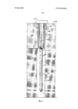
На фиг. 5 показан вид сбоку варианта осуществления соединения для стыковки участка в перекрывающей породе и нагревательного участка изолированного проводника, сердцевины которых имеют по существу один и тот же диаметр.In FIG. 5 is a side view of an embodiment of a joint for docking a portion in an overlapping rock and a heating portion of an insulated conductor, the cores of which have substantially the same diameter.
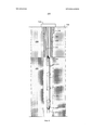
На фиг. 6 показан вид сбоку варианта осуществления соединения для стыковки участка в перекрывающей породе изолированного проводника, имеющего сердцевину большего диаметра с нагревательным участком изолированного проводника, имеющего сердцевину с меньшим диаметром.In FIG. 6 is a side view of an embodiment of a joint for docking a portion in an overlapping rock of an insulated conductor having a larger diameter core with a heating portion of an insulated conductor having a smaller diameter core.
На фиг. 7 показан вид сбоку другого варианта осуществления соединения для стыковки участка в перекрывающей породе изолированного проводника, имеющего сердцевину большего диаметра с нагревательным участком изолированного проводника, имеющего сердцевину с меньшим диаметром.In FIG. 7 is a side view of another embodiment of a joint for docking a portion in an overlapping rock of an insulated conductor having a larger diameter core with a heating portion of an insulated conductor having a smaller diameter core.
Хотя изобретение допускает различные модификации и альтернативные формы, отдельные варианты его осуществления показаны на чертежах в качестве примера и будут описаны подробно. Чертежи могут не быть выполненными в масштабе. Следует понимать, что не предполагается, что чертежи и подробное описание ограничивают изобретение конкретной описанной формой, а наоборот, предполагается, что оно покрывает все модификации, эквиваленты и альтернативы, попадающие под сущность и объем настоящего изобретения, как задано прилагаемой формулой определения.Although the invention is subject to various modifications and alternative forms, individual embodiments thereof are shown in the drawings by way of example and will be described in detail. Drawings may not be made to scale. It should be understood that the drawings and detailed description are not intended to limit the invention to the particular form described, but rather, it is intended to cover all modifications, equivalents, and alternatives that fall within the spirit and scope of the present invention as defined by the appended claims.
Осуществление изобретенияThe implementation of the invention
Нижеследующее описание, в целом, относится к системам и способам обработки углеводородов в пластах. Такие пласты могут быть обработаны для добычи углеводородных продуктов, водорода и других продуктов.The following description generally relates to systems and methods for treating hydrocarbons in formations. Such formations can be processed to produce hydrocarbon products, hydrogen, and other products.
Выражение "переменный ток (АС)" означает изменяющийся во времени ток, который меняет направление по существу синусоидально. Переменный производит поверхностный эффект в ферромагнитном проводнике.The expression "alternating current (AC)" means a time-varying current that changes direction essentially sinusoidally. The variable produces a surface effect in the ferromagnetic conductor.
Термин "соединенный" означает либо непосредственное соединение, либо непрямое соединение (например, одно или несколько промежуточных соединений) между одним или несколькими объектами или компонентами. Фраза "непосредственно соединенный" означает непосредственное соединение между объектами или компонентами, так что объекты или компоненты были соединены непосредственно друг с другом, так что объекты или компоненты функционируют "в месте использования".The term “connected” means either a direct connection or an indirect connection (for example, one or more intermediate compounds) between one or more objects or components. The phrase “directly connected” means a direct connection between objects or components, so that the objects or components are connected directly to each other, so that the objects or components function “in place of use”.
Термин "пласт" включает в себя один или несколько слоев, содержащих углеводороды, один или несколько слоев, не содержащих углеводороды, перекрывающую породу и/или подстилающую породу. Выражение "углеводородные слои" относится к слоям в пласте, которые содержат углеводороды. Углеводородные слои могут содержать неуглеводородный материал и углеводородный материал. Термины "перекрывающая порода" и/или "подстилающая порода" включают в себя один или несколько различных типов непроницаемых материалов. Например, перекрывающая и/или подстилающая порода может включать в себя скальную породу, сланец, аргиллит или влажную/плотную карбонатную породу. В некоторых вариантах осуществления в процессах термообработки пласта перекрывающая и/или подстилающая порода может включать в себя слои, содержащие углеводороды, или слои, не содержащие углеводороды, которые являются сравнительно непроницаемыми и не подвергаются воздействию температуры во время процесса термообработки пласта, что приводит к значительным изменениям характеристик слоев, содержащих углеводороды, перекрывающей и/или подстилающей породы. Например, подстилающая порода может содержать сланец или аргиллит, но во время термообработки пласта не допускается нагрев подстилающей породы до температур пиролиза. В некоторых случаях перекрывающая порода и/или подстилающая порода могут быть в какой-то степени проницаемыми.The term "formation" includes one or more layers containing hydrocarbons, one or more layers containing no hydrocarbons, overlapping rock and / or underlying rock. The term “hydrocarbon layers” refers to layers in a formation that contain hydrocarbons. The hydrocarbon layers may contain non-hydrocarbon material and hydrocarbon material. The terms "overburden" and / or "bedrock" include one or more different types of impermeable materials. For example, the overburden and / or bedrock may include rock, shale, mudstone, or wet / dense carbonate. In some embodiments, in formation heat treatment processes, the overburden and / or bedrock may include hydrocarbon containing layers or hydrocarbon-free layers that are relatively impermeable and not exposed to temperature during the formation heat treatment process, resulting in significant changes the characteristics of the layers containing hydrocarbons, overlapping and / or underlying rocks. For example, the underlying rock may contain shale or mudstone, but during the heat treatment of the formation is not allowed to heat the underlying rock to pyrolysis temperatures. In some cases, the overburden and / or bedrock may be somewhat permeable.
Выражение "пластовый флюид" означает текучие среды, присутствующие в пласте, и может включать в себя текучие среды пиролиза, синтез-газ, подвижные углеводороды и воду (пар). Пластовые флюиды могут включать в себя углеводородные флюиды, а также неуглеводородные флюиды. Термин "подвижные флюиды" означает флюиды в пласте, содержащем углеводороды, которые могут перетекать в результате термообработки пласта. Термин "добываемые флюиды" относится к флюидам, извлекаемым из пласта.The expression “formation fluid” means fluids present in the formation and may include pyrolysis fluids, synthesis gas, mobile hydrocarbons and water (steam). Formation fluids may include hydrocarbon fluids as well as non-hydrocarbon fluids. The term “moving fluids” means fluids in a formation containing hydrocarbons that may flow as a result of heat treatment of the formation. The term "produced fluids" refers to fluids recovered from the formation.
Выражение "источник тепла" представляет собой любую систему для подачи тепла, по меньшей мере, на участок пласта по существу с помощью кондуктивной/лучистой теплопередачи. Например, источник тепла может включать в себя электропроводные материалы и/или электронагреватели, такие как изолированный проводник, вытянутый элемент и/или проводник, расположенные в канале. Источник тепла также может включать в себя системы, которые вырабатывают теплоту путем сжигания топлива, являющегося внешними по отношению к пласту, или находящегося в пласте. Системы могут представлять собой поверхностные горелки, скважинные газовые горелки, беспламенные распределенные камеры сгорания и природные распределенные камеры сгорания. В некоторых вариантах осуществления тепло, подаваемое или вырабатываемое в одном или нескольких источниках тепла, может снабжаться другими источниками энергии. Другие источники энергии могут непосредственно нагревать пласт, либо энергия может передаваться на передающую среду, которая непосредственно или косвенно нагревает пласт. Следует понимать, что один или несколько источников тепла, которые подводят тепло к пласту, используют различные источники энергии. Таким образом, например, для данного пласта некоторые источники тепла могут подавать тепло от электропроводных материалов, резистивных электронагревателей, некоторые источники тепла могут подавать тепло от процесса горения, а некоторые источники тепла могут подавать тепло от одного или нескольких других источников энергии (например, от химических реакций, солнечную энергию, энергию ветра, биомассы или других источников возобновляемой энергии). Химическая реакция может включать в себя экзотермическую реакцию (например, реакцию окисления). Источник тепла также может включать в себя электропроводный материал и/или нагреватель, который подает тепло в зону, расположенную возле и/или окружающую место нагревания, такую как нагревательная скважина.The term “heat source” is any system for delivering heat to at least a portion of a formation using substantially conductive / radiant heat transfer. For example, a heat source may include electrically conductive materials and / or electric heaters, such as an insulated conductor, an elongated element, and / or a conductor located in the channel. The heat source may also include systems that generate heat by burning fuel that is external to or in the formation. Systems can be surface burners, downhole gas burners, flameless distributed combustion chambers, and natural distributed combustion chambers. In some embodiments, heat supplied or generated in one or more heat sources may be provided with other energy sources. Other energy sources can directly heat the formation, or energy can be transferred to a transmission medium that directly or indirectly heats the formation. It should be understood that one or more heat sources that supply heat to the formation use different energy sources. Thus, for example, for a given formation, some heat sources can supply heat from electrically conductive materials, resistive electric heaters, some heat sources can supply heat from the combustion process, and some heat sources can supply heat from one or more other energy sources (for example, from chemical reactions, solar energy, wind energy, biomass or other sources of renewable energy). A chemical reaction may include an exothermic reaction (e.g., an oxidation reaction). The heat source may also include an electrically conductive material and / or a heater that supplies heat to an area adjacent to and / or surrounding a heating location, such as a heating well.
"Нагреватель" - это любая система или источник тепла, предназначенный для выработки теплоты в скважине или в области возле скважины. Нагреватели могут представлять собой электронагреватели, горелки, камеры сгорания, которые осуществляют реакцию с веществом, расположенным или добываемым из пласта, и/или их сочетания, но, не ограничиваясь этим.A “heater” is any system or heat source designed to generate heat in a well or in an area near a well. Heaters can be electric heaters, burners, combustion chambers that react with a substance located or mined from the formation, and / or combinations thereof, but not limited to.
"Углеводороды", в общем, определяют как молекулы, образованные преимущественно из атомов углерода и водорода. Углеводороды также могут включать в себя другие элементы, такие как галогены, металлические элементы, азот, кислород и/или сера, но, не ограничиваясь этим. Углеводороды могут представлять собой кероген, битум, пиробитум, масла, природные минеральные воски и асфальтиты. Углеводороды могут быть расположены в скелетных породах в земле или примыкать к ним. Скелетные породы включают в себя осадочные породы, пески, силицилиты, карбонаты, диатомиты и другие пористые среды, но, не ограничиваясь этим. "Углеводородные флюиды" представляют собой флюиды, содержащие углеводороды. Углеводородные флюиды могут включать в себя, охватывать или быть охваченными неуглеводородными флюидами, такими как водород, азот, окись углерода, двуокись углерода, сероводород, вода и аммиак.“Hydrocarbons” are generally defined as molecules formed predominantly from carbon and hydrogen atoms. Hydrocarbons may also include other elements, such as, but not limited to, halogens, metal elements, nitrogen, oxygen and / or sulfur. Hydrocarbons can be kerogen, bitumen, pyrobitumen, oils, natural mineral waxes and asphalts. Hydrocarbons can be located in skeletal rocks in the earth or adjacent to them. Skeletal rocks include, but are not limited to, sedimentary rocks, sands, silicites, carbonates, diatomites, and other porous media. "Hydrocarbon fluids" are fluids containing hydrocarbons. Hydrocarbon fluids may include, cover, or be covered by non-hydrocarbon fluids such as hydrogen, nitrogen, carbon monoxide, carbon dioxide, hydrogen sulfide, water, and ammonia.
Выражение "процесс преобразования в пласте" относится к процессу нагревания пласта, содержащего углеводороды, с помощью источников тепла, чтобы поднять температуру, по меньшей мере, части пласта до температуры, превышающей температуру пиролиза, чтобы в пласте образовывался пиролизный флюид.The term “formation conversion process” refers to the process of heating a hydrocarbon containing formation using heat sources to raise the temperature of at least a portion of the formation to a temperature above the pyrolysis temperature so that pyrolysis fluid is generated in the formation.
Выражение "процесс термообработки в пласте" относится к процессу нагревания пласта, содержащего углеводороды, с помощью источников тепла, чтобы поднять температуру, по меньшей мере, части пласта до температуры, превышающей температуру, при которой возникает подвижный флюид, висбрекинг и/или пиролиз материала, содержащего углеводороды, чтобы в пласте образовывались подвижные флюиды, флюиды висбрекинга и/или пиролизные флюиды.The expression “heat treatment process in the formation” refers to the process of heating a hydrocarbon containing formation using heat sources to raise the temperature of at least a portion of the formation to a temperature higher than the temperature at which mobile fluid, visbreaking and / or pyrolysis of the material occurs, containing hydrocarbons so that mobile fluids, visbreaking fluids and / or pyrolysis fluids are formed in the formation.
Термин "изолированный проводник" означает любой вытянутый материал, который способен проводить электричество и который полностью или частично покрыт электроизоляционным материалом.The term "insulated conductor" means any elongated material that is capable of conducting electricity and which is fully or partially coated with an insulating material.
Термин "нитрид" означает соединение азота и одного или нескольких других элементов периодической таблицы. Нитриды включают в себя нитрид кремния, нитрид бора или глинозем, но, не ограничиваясь этим.The term "nitride" means a compound of nitrogen and one or more other elements of the periodic table. Nitrides include, but are not limited to, silicon nitride, boron nitride, or alumina.
Термин "отверстия" включает в себя отверстия, прорези, проемы или дырки в стенке канала, трубы, трубопровода или другой направляющей потока, которые позволяют втекать или вытекать из канала, трубы, трубопровода или другой направляющей потока.The term “openings” includes openings, slots, openings or holes in a wall of a channel, pipe, conduit or other flow guide that allows flow in or out of a channel, pipe, conduit or other flow guide.
"Пиролиз" представляет собой разрыв химических связей под действием прикладываемого тепла. Например, пиролиз может включать в себя преобразование соединения в одну или несколько других субстанций только под воздействием тепла. Тепло может быть передано к участку пласта для того, чтобы возник пиролиз."Pyrolysis" is the breaking of chemical bonds under the influence of applied heat. For example, pyrolysis may include converting the compound into one or more other substances only when exposed to heat. Heat can be transferred to the area of the formation so that pyrolysis occurs.
"Пиролизные флюиды" или "продукты пиролиза" относятся к флюидам, полученным по существу во время процесса пиролиза углеводородов. Флюиды, полученные при реакциях пиролиза, могут смешиваться с другими флюидами в пласте. Смесь можно рассматривать в качестве пиролизного флюида или продукта пиролиза. Используемый в этом документе термин "зона пиролиза" относится к объему пласта (например, сравнительно проницаемого пласта, такого как пласт нефтеносных песков), который подвергают реакции, или в котором происходит реакция для образования пиролизного флюида."Pyrolysis fluids" or "pyrolysis products" refer to fluids obtained substantially during the pyrolysis of hydrocarbons. Fluids obtained from pyrolysis reactions can mix with other fluids in the formation. The mixture can be considered as a pyrolysis fluid or a pyrolysis product. As used herein, the term “pyrolysis zone” refers to the volume of a formation (eg, a relatively permeable formation, such as oil sands) that is being reacted or in which a reaction takes place to form a pyrolysis fluid.
"Толщина" слоя означает толщину поперечного сечения слоя, причем поперечное сечение проходит по нормали к поверхности слоя.“Thickness” of a layer means the thickness of the cross section of the layer, the cross section extending normal to the surface of the layer.
Термин "скважина" обозначает отверстие в пласте, выполненное посредством бурения или вставки канала в пласт. Скважина может иметь по существу круглое поперечное сечение или другую форму поперечного сечения. Используемые в этом документе термины "колодец" и "отверстие" в контексте отверстия в пласте могут быть взаимозаменяемыми с термином "скважина".The term "well" means a hole in the formation made by drilling or inserting a channel into the formation. The well may have a substantially circular cross section or other cross sectional shape. As used herein, the terms “well” and “hole” in the context of a hole in a formation may be used interchangeably with the term “well”.
Чтобы получить разные продукты, пласт может быть подвергнут обработке различными способами. Для обработки пласта во время процесса термообработки могут использоваться различные этапы или процессы. В некоторых вариантах осуществления один или несколько участков пласта разрабатывают растворением, чтобы удалить растворимые минералы из участков. Добываемые растворением минералы могут быть произведены до, во время и/или после процесса термообработки пласта. В некоторых вариантах осуществления средняя температура одного или нескольких участков, добычу из которых осуществляют растворением, может поддерживаться ниже примерно 120°C.To obtain different products, the formation can be processed in various ways. Various stages or processes can be used to treat the formation during the heat treatment process. In some embodiments, one or more portions of the formation is developed by dissolution to remove soluble minerals from the sites. Minerals produced by dissolution can be produced before, during, and / or after the heat treatment of the formation. In some embodiments, the implementation of the average temperature of one or more areas, the extraction of which is carried out by dissolution, can be maintained below about 120 ° C.
В некоторых вариантах осуществления один или несколько участков пласта нагревают, чтобы удалить воду из участков и/или чтобы удалить метан и другие летучие углеводороды из участков. В некоторых вариантах осуществления в процессе удаления воды и летучих углеводородов средняя температура может быть поднята от температуры окружающей среды до температур ниже примерно 220°C.In some embodiments, one or more portions of the formation is heated to remove water from the sites and / or to remove methane and other volatile hydrocarbons from the sites. In some embodiments, during the process of removing water and volatile hydrocarbons, the average temperature may be raised from ambient temperature to temperatures below about 220 ° C.
В некоторых вариантах осуществления один или несколько участков пласта нагревают до температур, которые допускают перемещение и/или висбрекинг углеводородов в пласте. В некоторых вариантах осуществления средняя температура одного или нескольких участков пласта может быть поднята до температур активации углеводородов в участках (например, до температур из диапазона от 100°C до 250°C, от 120°C до 240°C или от 150°C до 230°C).In some embodiments, one or more portions of the formation is heated to temperatures that allow movement and / or visbreaking of hydrocarbons in the formation. In some embodiments, the average temperature of one or more sections of the formation may be raised to the activation temperatures of hydrocarbons in the areas (for example, temperatures from a range of 100 ° C to 250 ° C, 120 ° C to 240 ° C, or 150 ° C to 230 ° C).
В некоторых вариантах осуществления один или несколько участков нагревают до температур, которые допускают реакции пиролиза в пласте. В некоторых вариантах осуществления средняя температура одного или нескольких участков пласта может быть поднята до температур пиролиза углеводородов в участках (например, до температур из диапазона от 230°C до 900°C, от 240°C до 400°C или от 250°C до 350°C).In some embodiments, one or more sections are heated to temperatures that allow for pyrolysis reactions in the formation. In some embodiments, the average temperature of one or more sections of the formation may be raised to the pyrolysis temperatures of hydrocarbons in the areas (for example, temperatures from a range of 230 ° C to 900 ° C, 240 ° C to 400 ° C, or 250 ° C to 350 ° C).
Нагревание пласта, содержащего углеводороды, с помощью нескольких источников тепла может установить термические градиенты вокруг источников тепла, которые поднимают температуру углеводородов в пласте до желаемых температур с желаемыми скоростями нагрева. Скорость увеличения температуры через диапазон температур активации и/или диапазон температур пиролиза для желаемых продуктов может повлиять на качество и количество пластовых флюидов, получаемых из пласта, содержащего углеводороды. Медленно поднимая температуру пласта через диапазон температур активации и/или диапазон температур пиролиза, можно допустить получение из пласта углеводородов высокого качества, высокой плотности. Медленно поднимая температуру пласта через диапазон температур активации и/или диапазон температур пиролиза, можно позволить извлечь большое количество углеводородов, присутствующих в пласте в качестве углеводородного продукта.Heating a hydrocarbon containing formation using multiple heat sources can establish thermal gradients around heat sources that raise the temperature of the hydrocarbons in the formation to desired temperatures with desired heating rates. The rate of temperature increase through the range of activation temperatures and / or the range of pyrolysis temperatures for the desired products may affect the quality and quantity of formation fluids obtained from the formation containing hydrocarbons. Slowly raising the formation temperature through the activation temperature range and / or the pyrolysis temperature range, it is possible to obtain high-quality, high-density hydrocarbons from the formation. By slowly raising the formation temperature through the activation temperature range and / or the pyrolysis temperature range, it is possible to recover a large amount of hydrocarbons present in the formation as a hydrocarbon product.
В некоторых вариантах осуществления термообработки пласта участок пласта нагревают до желаемой температуры вместо медленного нагрева через диапазон температур. В некоторых вариантах осуществления желаемая температура составляет 300°C, 325°C или 350°C. В качестве желаемой температуры можно выбрать другое значение.In some embodiments of a heat treatment of a formation, a portion of the formation is heated to a desired temperature instead of slowly heating through a temperature range. In some embodiments, the desired temperature is 300 ° C, 325 ° C, or 350 ° C. You can select a different value as the desired temperature.
Суперпозиция теплоты от источников тепла позволяет установить в пласте желаемую температуру сравнительно быстро и эффективно. Подводимая в пласт энергия от источников тепла может быть отрегулирована так, чтобы поддерживать в пласте по существу желаемую температуру.The superposition of heat from heat sources allows you to set the desired temperature in the formation relatively quickly and efficiently. The energy supplied to the formation from heat sources can be adjusted to maintain a substantially desired temperature in the formation.
Продукты активации и/или пиролиза могут быть получены из пласта через эксплуатационные скважины. В некоторых вариантах осуществления среднюю температуру одного или нескольких участков поднимают до температур активации, и из эксплуатационных скважин получают углеводороды. Средняя температура одного или нескольких участков может быть поднята до температур пиролиза после того, как выход из-за активации опустится ниже выбранного значения. В некоторых вариантах осуществления средняя температура одного или нескольких участков может быть поднята до температур пиролиза без значительного выхода до достижения температур пиролиза. Пластовые флюиды, включая продукты пиролиза, могут быть получены через эксплуатационные скважины.Activation and / or pyrolysis products can be obtained from the formation through production wells. In some embodiments, the average temperature of one or more sites is raised to activation temperatures, and hydrocarbons are produced from production wells. The average temperature of one or more sections can be raised to pyrolysis temperatures after the output due to activation drops below the selected value. In some embodiments, the average temperature of one or more sections can be raised to pyrolysis temperatures without significant yield until pyrolysis temperatures are reached. Formation fluids, including pyrolysis products, can be obtained through production wells.
В некоторых вариантах осуществления средняя температура одного или нескольких участков может быть поднята до температур достаточных для того, чтобы после активации и пиролиза допустить выход синтез-газа. В некоторых вариантах осуществления, углеводороды могут быть нагреты до температур, достаточных для того, чтобы допустить выход синтез-газа без значительного выхода до достижения температур, достаточных для того, чтобы допустить выход синтез-газа. Например, синтез-газ может быть получен в диапазоне температур примерно от 400°C до 1200°C, от 500°C до 1100°C или от 550°C до 1000°C. Текучая среда, вырабатывающая синтез-газ (например, пар и/или вода) может быть введена в участки для выработки синтез-газа. Синтез-газ может быть получен из эксплуатационных скважин.In some embodiments, the average temperature of one or more sites can be raised to temperatures sufficient to allow synthesis gas to escape after activation and pyrolysis. In some embodiments, the hydrocarbons may be heated to temperatures sufficient to allow the synthesis gas to exit without significant output until temperatures are sufficient to allow the synthesis gas to exit. For example, synthesis gas can be obtained in a temperature range of from about 400 ° C to 1200 ° C, from 500 ° C to 1100 ° C, or from 550 ° C to 1000 ° C. A synthesis gas generating fluid (e.g., steam and / or water) may be introduced into the synthesis gas generating sections. Synthesis gas can be obtained from production wells.
Добыча растворением, извлечение летучих углеводородов и воды, активация углеводородов, пиролиз углеводородов, выработка синтез-газа и/или другие процессы могут быть выполнены во время процесса термообработки пласта. В некоторых вариантах осуществления некоторые процессы могут быть выполнены после процесса термообработки пласта. Такие процессы могут включать в себя восстановление тепла от обработанных участков, сохранение текучих сред (например, воды и/или углеводородов) в ранее обработанных участках и/или отделение диокиси углерода в ранее обработанных участках.Dissolution mining, volatile hydrocarbon and water recovery, hydrocarbon activation, hydrocarbon pyrolysis, synthesis gas generation and / or other processes can be performed during the heat treatment of the formation. In some embodiments, some processes may be performed after the heat treatment of the formation. Such processes may include recovering heat from treated areas, retaining fluids (e.g., water and / or hydrocarbons) in previously treated areas, and / or separating carbon dioxide in previously treated areas.
На фиг. 1 показан схематический вид варианта осуществления участка системы термической обработки, предназначенной для обработки пласта, содержащего углеводороды. Система термической обработки пласта может включать в себя барьерные скважины 200. Барьерные скважины используют для того, чтобы образовать барьер вокруг обрабатываемой области. Барьер препятствует потоку флюидов в обрабатываемой области и/или из нее. Барьерная скважина включает в себя водопонижающие скважины, вакуумные скважины, захватывающие скважины, нагнетательные скважины, цементирующие скважины, морозильные скважины и их сочетания, но, не ограничиваясь этим. В некоторых вариантах осуществления барьерные скважины 200 представляют собой водопонижающие скважины. Водопонижающие скважины могут удалять жидкую воду и/или препятствовать поступлению жидкой воды в участок пласта, который надо нагреть, или в нагреваемый пласт. В варианте осуществления, показанном на фиг. 1, барьерные скважины 200 показаны проходящими только вдоль одной стороны источников 202 тепла, но барьерные скважины обычно окружают все используемые источники 202 тепла или источники, которые надо использовать, чтобы нагреть обрабатываемую область пласта.In FIG. 1 is a schematic view of an embodiment of a portion of a heat treatment system for treating a hydrocarbon containing formation. The heat treatment system of the formation may include
Источники 202 тепла размещают, по меньшей мере, в части пласта. Источники 202 тепла могут включать в себя нагреватели, такие как изолированные проводники, нагреватели с проводником в канале, поверхностные горелки, беспламенные распределенные камеры сгорания и/или природные распределенные камеры сгорания. Источники 202 тепла также могут включать в себя другие типы нагревателей. Источники 202 тепла подают тепло, по меньшей мере, в часть пласта, чтобы нагреть углеводороды в пласте. Энергия может подаваться к источникам 202 тепла через линии 204 питания. Лини 204 питания могут структурно отличаться, в зависимости от типа источника тепла или источников тепла, используемых для нагрева пласта. Линии 204 питания для источников тепла могут передавать электричество для электронагревателей, топливо для камер сгорания, или могут передавать теплообменную текучую среду, которая циркулирует в пласте. В некоторых вариантах осуществления электричество для процесса термообработки пласта может обеспечиваться атомной электростанцией или атомными электростанциями. Использование атомной энергии может позволить сократить или ограничить выбросы окиси углерода в процессе термообработки пласта.
Когда пласт нагревают, поступление тепла в пласт может вызвать расширение пласта и геомеханическое перемещение. Источники тепла могут быть включены до, вместе или во время процесса обезвоживания. Реакцию пласта на нагрев можно смоделировать посредством компьютерной симуляции. Компьютерная симуляция может быть использована для разработки шаблона и последовательности активизации источников тепла в пласте так, чтобы геомеханическое перемещение пласта не оказало неблагоприятного воздействия на функциональность источников тепла, эксплуатационных скважин и другого оборудования в пласте.When the formation is heated, the entry of heat into the formation can cause expansion of the formation and geomechanical movement. Heat sources may be included before, together with, or during the dehydration process. The response of the formation to heat can be modeled by computer simulation. Computer simulation can be used to develop a pattern and sequence of activation of heat sources in the formation so that the geomechanical movement of the formation does not adversely affect the functionality of heat sources, production wells and other equipment in the formation.
Нагрев пласта может привести к увеличению проницаемости и/или пористости пласта. Увеличение проницаемости и/или пористости может привести к сокращению массы в пласте из-за испарения и удаления воды, удаления углеводородов и/или возникновения трещин. Текучая среда может легко течь в нагретый участок пласта, благодаря увеличенной проницаемости и/или пористости пласта. Благодаря увеличенной проницаемости и/или пористости пласта, текучая среда в нагретом участке пласта может перемещаться на значительное расстояние через пласт. Значительное расстояние может превышать 1000 м, в зависимости от различных факторов, таких как проницаемость пласта, свойства текучей среды, температура пласта и градиент давления, допускающий перемещение текучей среды. Способность текучей среды перемещаться на значительное расстояние в пласте позволяет расположить эксплуатационные скважины 206 сравнительно далеко от пласта.Heating the formation can lead to an increase in permeability and / or porosity of the formation. An increase in permeability and / or porosity can lead to a reduction in mass in the formation due to evaporation and removal of water, removal of hydrocarbons and / or cracking. Fluid can easily flow into a heated portion of the formation due to increased permeability and / or porosity of the formation. Due to the increased permeability and / or porosity of the formation, the fluid in the heated portion of the formation can travel a considerable distance through the formation. A considerable distance can exceed 1000 m, depending on various factors, such as formation permeability, fluid properties, formation temperature, and pressure gradient allowing fluid to move. The ability of the fluid to travel a considerable distance in the formation allows
Эксплуатационные скважины 206 используют для извлечения пластового флюида из пласта. В некоторых вариантах осуществления эксплуатационная скважина 206 включает в себя источник тепла. Источник тепла в эксплуатационной скважине может нагревать один или несколько участков пласта в эксплуатационной скважине или рядом с ней. В некоторых вариантах осуществления процесса термообработки пласта количество теплоты, подаваемой в пласт от эксплуатационной скважины на метр эксплуатационной скважины, меньше, чем количество теплоты, подаваемой в пласт от источника тепла, который нагревает пласт, на метр источника тепла. Теплота, подаваемая в пласт от эксплуатационной скважины, может увеличить проницаемость пласта возле эксплуатационной скважины посредством испарения и удаления флюида жидкой фазы возле эксплуатационной скважины и/или путем увеличения проницаемости пласта возле эксплуатационной скважины из-за формирования макро и/или микротрещин.
В эксплуатационной скважине может быть расположено более одного источника тепла. Источник тепла в нижнем участке эксплуатационной скважины может быть выключен, если суперпозиция теплоты от смежных источников тепла нагревает пласт достаточно, чтобы нейтрализовать преимущества, обеспечиваемые нагревом пласта от эксплуатационной скважины. В некоторых вариантах осуществления источник тепла в верхнем участке эксплуатационной скважины может оставаться включенным после выключения источника тепла в нижнем участке эксплуатационной скважины. Источник тепла в верхнем участке скважины может препятствовать конденсации и обратному стоку пластового флюида.A production well may have more than one heat source. The heat source in the lower section of the production well can be turned off if a superposition of heat from adjacent heat sources heats the formation enough to neutralize the benefits of heating the formation from the production well. In some embodiments, the heat source in the upper portion of the production well may remain on after the heat source in the lower portion of the production well is turned off. A heat source in the upper portion of the well may impede condensation and backflow of formation fluid.
В некоторых вариантах осуществления источник тепла в эксплуатационной скважине 206 позволяет удалять пластовые флюиды в виде пара из пласта. Обеспечение нагрева в эксплуатационной скважине или через нее может: (1) препятствовать конденсации и/или обратному стоку пластового флюида, если такой пластовый флюид перемещается в эксплуатационной скважине вблизи от перекрывающей породы, (2) увеличить поступление тепла в пласт, (3) увеличить дебит эксплуатационной скважины по сравнению с эксплуатационной скважиной без источника тепла, (4) препятствовать конденсации высокоуглеродистых соединений (С6 углеводородов и более тяжелых) в эксплуатационной скважине и/или (5) увеличить проницаемость пласта в эксплуатационной скважине или возле нее.In some embodiments, a heat source in
Подземное давление в пласте может соответствовать давлению текучей среды, вырабатываемой в пласте. По мере увеличение температур в нагретом участке давление в нагретом участке может увеличиваться в результате теплового расширения присутствующих в нем флюидов, увеличенного образования флюидов и испарения воды. Управляя скоростью удаления флюидов из пласта, можно управлять давлением в пласте. Давление в пласте можно определить во множестве различных мест, например, возле эксплуатационной скважины или в ней, возле или у источников тепла или в контрольных скважинах.The subsurface pressure in the formation may correspond to the pressure of the fluid generated in the formation. As temperatures increase in the heated portion, the pressure in the heated portion may increase as a result of thermal expansion of the fluids present in it, increased formation of fluids, and evaporation of water. By controlling the rate of fluid removal from the formation, it is possible to control the pressure in the formation. The pressure in the formation can be determined in many different places, for example, near or in the production well, near or near heat sources or in control wells.
В некоторых пластах, содержащих углеводороды, препятствуют выходу углеводородов из пласта до тех пор, пока, по меньшей мере, некоторые углеводороды в пласте не будут активированы и/или пиролизованы. Пластовый флюид может быть получен из пласта, когда пластовый флюид обладает выбранным свойством. В некоторых вариантах осуществления выбранное свойство включает в себя плотность в градусах Американского нефтяного института (АНИ), равную, по меньшей мере, 20°, 30° или 40°. Препятствие выходу до тех пор, пока, по меньшей мере, некоторые углеводороды в пласте не будут активированы и/или пиролизованы, может увеличить преобразование тяжелых углеводородов в легкие углеводороды. Препятствие начальному выходу может минимизировать выход тяжелых углеводородов из пласта. Выход существенного количества тяжелых углеводородов может потребовать дорогостоящего оборудования и/или сокращения срока службы производственного оборудования.In some hydrocarbon containing formations, hydrocarbons are prevented from leaving the formation until at least some hydrocarbons in the formation are activated and / or pyrolyzed. Formation fluid may be obtained from the formation when the formation fluid has a selected property. In some embodiments, the selected property includes a density in degrees of the American Petroleum Institute (ANI) of at least 20 °, 30 °, or 40 °. An obstacle to exit until at least some hydrocarbons in the formation are activated and / or pyrolyzed can increase the conversion of heavy hydrocarbons to light hydrocarbons. Obstruction of the initial exit can minimize the release of heavy hydrocarbons from the reservoir. The release of a significant amount of heavy hydrocarbons may require expensive equipment and / or shorten the life of the production equipment.
В некоторых пластах, содержащих углеводороды, углеводороды в пласте могут быть нагреты до температур активации и/или пиролиза до того, как в нагретом участке пласта возникнет существенная проницаемость. Начальное отсутствие проницаемости может препятствовать транспортировке выработанных флюидов к эксплуатационным скважинам 206. Во время начального нагревания давление флюидов в пласте может увеличиваться возле источников 202 тепла. Увеличенное давление флюидов может быть сброшено, проконтролировано, изменено и/или может управляться с помощью одного или нескольких источников 202 тепла. Например, выбранные источники 202 тепла или отдельные скважины понижения давления могут включать в себя клапаны понижения давления, которые позволяют удалить некоторые флюиды из пласта.In some hydrocarbon containing formations, hydrocarbons in the formation may be heated to activation and / or pyrolysis temperatures before significant permeability occurs in the heated portion of the formation. An initial lack of permeability may impede the transportation of produced fluids to
В некоторых вариантах осуществления может допускаться увеличение давления, возникающего из-за расширения подвижных флюидов пиролизных флюидов или других флюидов, выработанных в пласте, несмотря на то, что в пласте может еще отсутствовать открытый путь к эксплуатационным скважинам 206 или другая утечка давления. Может допускаться увеличение давления флюидов до пластового давления. Трещины в пласте, содержащем углеводороды, могут образовываться, если флюид достигает пластового давления. Например, в нагретом участке пласта могут образоваться трещины от источников 202 тепла до эксплуатационных скважин 206. Возникновение трещин в нагретом участке может сбросить часть давления в участке. Может быть необходимо поддерживать давление в пласте ниже выбранного давления, чтобы препятствовать нежелательному выходу, появлению трещин в перекрывающей или подстилающей породе и/или коксованию углеводородов в пласте.In some embodiments, an increase in pressure resulting from the expansion of mobile fluids of pyrolysis fluids or other fluids generated in the formation may be allowed, although there may still be no open path to
После того, как достигнуты температуры активации и/или пиролиза и разрешен выход из пласта, давление в пласте может быть изменено, чтобы изменить и/или управлять составом получаемого пластового флюида, чтобы управлять долей конденсирующегося флюида по сравнению с неконденсирующимся флюидом в пластовом флюиде и/или чтобы управлять плотностью получаемого пластового флюида. Например, снижение давления может привести к выходу большего количества компонента конденсирующегося флюида. Компонент конденсирующегося флюида может содержать большую долю олефинов.Once the activation and / or pyrolysis temperatures are reached and exit from the formation is allowed, the pressure in the formation can be changed to change and / or control the composition of the resulting formation fluid to control the fraction of the condensed fluid compared to the non-condensable fluid in the reservoir fluid and / or to control the density of the resulting formation fluid. For example, a decrease in pressure may result in the release of a larger component of the condensing fluid. The condensing fluid component may contain a large proportion of olefins.
В некоторых вариантах осуществления процесса термообработки пласта в пласте может удерживаться давление достаточно высокое, чтобы способствовать выходу пластового флюида, имеющего плотность в градусах АНИ более 20°. Поддержание увеличенного давления в пласте может препятствовать оседанию пласта во время термообработки. Поддержание увеличенного давления может снизить или устранить потребность в сжатии пластовых флюидов у поверхности, чтобы транспортировать флюиды по коллекторным каналам к очистным сооружениям.In some embodiments of the process of heat treatment of the formation in the formation, the pressure can be kept high enough to facilitate the output of the formation fluid having a density in degrees of API greater than 20 °. Maintaining increased pressure in the formation may interfere with subsidence of the formation during heat treatment. Maintaining increased pressure can reduce or eliminate the need to compress formation fluids at the surface in order to transport fluids through the collector channels to treatment facilities.
Как ни удивительно, поддержание увеличенного давления в нагретом участке пласта может допускать выход большого количества углеводородов повышенного качества и сравнительно малого молекулярного веса. Давление может поддерживаться так, что получаемый пластовый флюид обладает минимальным количеством соединений, углеродное число которых превосходит выбранное углеродное число. Выбранное углеродное число может быть не больше 25, не больше 20, не больше 12 или не больше 8. Некоторые соединения с высоким углеродным числом могут быть увлечены паром в пласте и могут быть удалены из пласта с паром. Поддержание увеличенного давления в пласте может препятствовать увлечению паром соединений с высоким углеродным числом и/или полициклических углеводородных составляющих. Соединения с высоким углеродным числом и/или полициклические углеводородные составляющие могут оставаться в жидкой фазе в пласте в течение значительных периодов времени. Значительные периоды времени могут обеспечить достаточное время для того, чтобы соединения пиролизовались для образования соединений с низким углеродным числом.Surprisingly, maintaining increased pressure in a heated section of the formation can allow the release of a large amount of high quality hydrocarbons and a relatively low molecular weight. The pressure can be maintained so that the resulting formation fluid has a minimum number of compounds, the carbon number of which exceeds the selected carbon number. The carbon number selected may be no more than 25, no more than 20, no more than 12, or no more than 8. Some compounds with a high carbon number may be entrained by steam in the formation and may be removed from the formation with steam. Maintaining increased pressure in the formation may prevent steam entrainment of high carbon number compounds and / or polycyclic hydrocarbon constituents. Compounds with a high carbon number and / or polycyclic hydrocarbon moieties may remain in the liquid phase in the formation for significant periods of time. Significant periods of time may provide sufficient time for the compounds to pyrolyze to form compounds with a low carbon number.
Полагают, что выработка углеводородов, обладающих сравнительно низким молекулярным весом, частично происходит из-за автогенной выработки и реакции углеводорода в части пласта, содержащего углеводороды. Например, поддержание увеличенного давления может заставить углеводород, выработанный во время пиролиза, перейти в жидкую фазу в пласте. Нагрев участка до температуры, находящейся в диапазоне температур пиролиза, может пиролизовать углеводороды в пласте для получения жидкой фазы пиролизных флюидов. Компоненты полученной жидкой фазы пиролизных флюидов могут включать в себя ненасыщенные связи и/или радикалы. Водород (H2) в жидкой фазе может сократить ненасыщенные связи выработанных пиролизных флюидов, тем самым, сокращая потенциал для полимеризации или образования длинноцепочечных соединений из выработанных пиролизных флюидов. Кроме того, H2 также может нейтрализовать радикалы в выработанных пиролизных флюидах. H2 в жидкой фазе может препятствовать возникновению реакции выработанных пиролизных флюидов друг с другом и/или с другими соединениями в пласте.It is believed that the production of hydrocarbons having a relatively low molecular weight is partially due to autogenous production and the reaction of a hydrocarbon in a portion of a hydrocarbon containing formation. For example, maintaining increased pressure may cause the hydrocarbon produced during pyrolysis to transfer to the liquid phase in the formation. Heating the site to a temperature in the pyrolysis temperature range can pyrolyze hydrocarbons in the formation to produce a liquid phase of pyrolysis fluids. The components of the resulting liquid phase of the pyrolysis fluids may include unsaturated bonds and / or radicals. Hydrogen (H 2 ) in the liquid phase can reduce the unsaturated bonds of the generated pyrolysis fluids, thereby reducing the potential for polymerization or the formation of long chain compounds from the generated pyrolysis fluids. In addition, H 2 can also neutralize radicals in the generated pyrolysis fluids. H 2 in the liquid phase can inhibit the reaction of the generated pyrolysis fluids with each other and / or with other compounds in the formation.
Пластовый флюид, полученный из эксплуатационных скважин 206, может быть транспортирован через коллекторный трубопровод 208 к очистным сооружениям. Пластовые флюиды также могут быть получены от источников 202 тепла. Например, флюид может быть получен от источников 202 тепла, чтобы управлять давлением в пласте, прилегающем к источникам тепла. Флюид, полученный от источников 202 тепла, может быть транспортирован через трубу или трубопровод в коллекторный трубопровод 208, или полученный флюид может быть транспортирован через трубу или трубопровод непосредственно к очистным сооружениям 210. Очистные сооружения 210 могут включать в себя сепарационные установки, реакторные установки, обогащающие установки, топливные элементы, турбины, сосуды для хранения и/или другие системы и установки для обработки полученных пластовых флюидов. Очистные сооружения могут получать транспортное топливо, по меньшей мере, из части добытых из пласта углеводородов. В некоторых вариантах осуществления транспортное топливо может представлять собой реактивное топливо, такое как JP-8.Formation fluid obtained from
В качестве электрического нагревательного элемента нагревателя или источника тепла может использоваться изолированный проводник. Изолированный проводник может включать в себя внутренний электрический проводник (сердцевину), окруженный электрическим изолятором, и внешний электрический проводник (оболочку). Электрический изолятор может включать в себя минеральную изоляцию (например, окись магния) или другую электрическую изоляцию.An insulated conductor may be used as the electric heating element of the heater or heat source. The insulated conductor may include an internal electrical conductor (core) surrounded by an electrical insulator and an external electrical conductor (sheath). An electrical insulator may include mineral insulation (e.g., magnesium oxide) or other electrical insulation.
В отдельных вариантах осуществления изолированный проводник размещают в скважине в пласте, содержащем углеводороды. В некоторых вариантах осуществления изолированный проводник размещают в необсаженной скважине в пласте, содержащем углеводороды. Размещение изолированного проводника в необсаженной скважине в пласте, содержащем углеводороды, может допустить теплопередачу от изолированного проводника в пласт посредством излучения, а также проводимости. Использование необсаженной скважины может при необходимости упростить извлечение изолированного проводника из скважины.In certain embodiments, an insulated conductor is placed in a well in a hydrocarbon containing formation. In some embodiments, an insulated conductor is placed in an open hole in a hydrocarbon containing formation. Placing an insulated conductor in an open hole in a hydrocarbon containing formation may allow heat transfer from the insulated conductor to the formation through radiation as well as conductivity. Using an open hole can, if necessary, simplify the extraction of an insulated conductor from the well.
В некоторых вариантах осуществления изолированный проводник размещают в обсадной трубе в пласте; он может быть зацементирован в пласте; или может быть расположен в скважине, заполненной песком, гравием или другим наполнительным материалом. Изолированный проводник может опираться на опорный элемент, расположенный в скважине. Опорный элемент может представлять собой кабель, стержень или канал (например, трубопровод). Опорный элемент может быть изготовлен из металла, керамики, неорганического материала или их сочетаний. Так как при использовании участки опорного элемента могут быть подвержены воздействию пластовых флюидов и теплоте, то опорные элементы могут быть химически стойкими и/или термически стойкими.In some embodiments, an insulated conductor is placed in a casing in the formation; it can be cemented in the formation; or may be located in a well filled with sand, gravel or other filler material. The insulated conductor can be supported by a support element located in the well. The support member may be a cable, rod, or conduit (e.g., conduit). The support element may be made of metal, ceramic, inorganic material, or combinations thereof. Since in use, portions of the support member may be exposed to formation fluids and heat, the support members may be chemically resistant and / or thermally stable.
Для соединения изолированного проводника с опорным элементом в различных местах вдоль протяженности изолированного проводника могут использоваться стяжки, точечная сварка и/или друге типы соединений. Опорный элемент может быть присоединен к устью скважины у верхней поверхности пласта. В некоторых вариантах осуществления изолированный проводник обладает достаточной прочностью конструкции так, что опорный элемент не требуется. Во многих случаях изолированный проводник может обладать, по меньшей мере, некоторой гибкостью, чтобы препятствовать повреждениям от теплового расширения при изменениях температуры.To connect the insulated conductor with the support element in various places along the length of the insulated conductor, ties, spot welding and / or other types of connections can be used. The support element may be attached to the wellhead at the top of the formation. In some embodiments, the insulated conductor has sufficient structural strength so that a support member is not required. In many cases, the insulated conductor may have at least some flexibility to prevent damage from thermal expansion due to temperature changes.
В отдельных вариантах осуществления изолированные проводники размещают в скважинах без опорных элементов и/или центраторов. Изолированный проводник без опорных элементов и/или центраторов может обладать подходящим сочетанием стойкости к температуре и коррозии, устойчивости против ползучести, длины, толщины (диаметра) и металлургии, что будет препятствовать возникновению неисправностей изолированного проводника во время использования.In certain embodiments, insulated conductors are placed in wells without support elements and / or centralizers. An insulated conductor without supporting elements and / or centralizers may have a suitable combination of resistance to temperature and corrosion, resistance to creep, length, thickness (diameter) and metallurgy, which will prevent the occurrence of malfunctions of the insulated conductor during use.
На фиг. 2 показан вид в перспективе концевого участка варианта осуществления изолированного проводника 212. Изолированный проводник 212 может обладать любой желаемой формой поперечного сечения, например, круглой (показанной на фиг. 2), треугольной, эллипсоидной, прямоугольной, шестиугольной или неправильной, но, не ограничиваясь этим. В отдельных вариантах осуществления изолированный проводник 212 включает в себя сердцевину 214, электрический изолятор 216 и оболочку 218. Сердцевина 214 может резистивно нагреваться, когда через сердцевину проходит электрический ток. Для подачи энергии на сердцевину 214 может использоваться переменный или меняющийся во времени ток и/или постоянный ток, так что сердцевина резистивно нагревается.In FIG. 2 is a perspective view of an end portion of an embodiment of an
В некоторых вариантах осуществления электрический изолятор 216 препятствует утечке тока и возникновению электрического пробоя на оболочку 218. Электрический изолятор 218 может термически проводить тепло, вырабатываемое в сердцевине 214, на оболочку 218. Оболочка 218 может излучать или проводить тепло в пласт. В отдельных вариантах осуществления изолированный проводник 212 имеет длину 1000 м или больше. Также могут использоваться более длинные или более короткие изолированные проводники, чтобы удовлетворить специфическим потребностям приложения. Размеры сердцевины 214, электрического изолятора 216 и оболочки 218 изолированного проводника 212 могут быть выбраны так, чтобы изолированный проводник обладал достаточной прочностью, чтобы поддерживать самого себя даже при верхних границах рабочей температуры. Такие изолированные проводники могут быть подвешены от устья скважин или опор, расположенных возле поверхности раздела между перекрывающей породой и пластом, содержащим углеводороды, без необходимости в опорных элементах, проходящих в пласт, содержащий углеводороды, вместе с изолированными проводниками.In some embodiments, the
Изолированный проводник 212 может быть сконструирован так, чтобы функционировать при уровнях мощности вплоть до примерно 1650 Вт/м или выше. В отдельных вариантах осуществления изолированный проводник 212 при нагревании пласта функционирует на уровне мощности между примерно 500 Вт/м и 1150 Вт/м. Изолированный проводник 212 может быть сконструирован так, чтобы максимальный уровень напряжения при обычной рабочей температуре не приводил к существенному термическому и/или электрическому распаду электрического изолятора 216. Изолированный проводник 212 может быть сконструирован так, чтобы оболочка 218 не превышала температуры, которая приведет к значительному сокращению свойств коррозионной стойкости материала оболочки. В отдельных вариантах осуществления изолированный проводник 212 может быть сконструирован так, чтобы достигать температур в диапазоне от примерно 650°C до примерно 900°C. Могут быть выполнены изолированные проводники, имеющие другие рабочие диапазоны, чтобы удовлетворить специфическим техническим требованиям.The
На фиг. 2 изображен изолированный проводник 212, имеющий единственную сердцевину 214. В некоторых вариантах осуществления изолированный проводник 212 содержит две или более сердцевины 214. Например, один изолированный проводник может иметь три сердцевины. Сердцевина 214 может быть выполнена из металла или другого электропроводного материала. Материал, используемый для выполнения сердцевины 214, может включать в себя нихром, медь, никель, углеродистую сталь и их сочетания, но, не ограничиваясь этим. В отдельных вариантах осуществления сердцевину 214 выбирают так, чтобы она имела диаметр и сопротивление при рабочих температурах такое, что ее сопротивление, полученное по закону Ома, делает ее электрически и структурно устойчивой для выбранного рассеяния мощности на метр, длины нагревателя и/или максимального напряжения, допустимого для материала сердцевины.In FIG. 2 shows an
В некоторых вариантах осуществления сердцевина 214 выполнена из различных материалов вдоль протяженности изолированного проводника 212. Например, первый участок сердцевины 214 может быть выполнен из материала, имеющего значительно более низкое сопротивление, чем второй участок сердцевины. Первый участок может быть размещен у слоя пласта, который не нужно нагревать до такой же высокой температуры, что второй слой пласта, примыкающий ко второму участку. Удельное сопротивление различных участков сердцевины 214 может быть отрегулировано путем изменяющейся величины диаметра и/или посредством участков сердцевины, выполненных из различных материалов.In some embodiments, the
Электрический изолятор 216 может быть выполнен из множества материалов. Используемые обычно порошки могут включать в себя MgO, Al2O3, BN, Si3N4, цирконий, BeO, различные химические вариации шпинелей и их сочетания, но, не ограничиваясь этим. MgO может обеспечивать хорошую теплопроводность и электрическую изоляцию. Желаемые свойства электрической изоляции включают в себя низкий ток утечки и высокую диэлектрическую прочность. Низкий ток утечки снижает вероятность теплового пробоя, а высокая диэлектрическая прочность снижает вероятность пробоя через изолятор. Тепловой пробой может возникнуть, если ток утечки приведет к прогрессирующему подъему температуры изолятора, что также приводит к пробою через изолятор.
Оболочка 218 может представлять собой внешний металлический слой или электропроводный слой. Оболочка 218 может контактировать с горячими пластовыми флюидами. Оболочка 218 может быть выполнена из материала, обладающего высокой стойкостью к коррозии при высоких температурах. Сплавы, которые можно использовать в желаемом диапазоне температур оболочки 218 включают в себя, но, не ограничиваясь, нержавеющую сталь марки 304, нержавеющую сталь марки 310, инколой® 800 и инконель® 600 (Западная Вирджиния, США (Inco Alloys International, Хантингтон, Западная Вирджиния, США). Может быть необходимой такая толщина оболочки 218, чтобы она была достаточной для того, чтобы выдерживать от трех до десяти лет в горячей и коррозионной среде. Толщина оболочки 218, в целом, может изменяться примерно от 1 мм до 2,5 мм. Например, внешний слой толщиной 1,3 мм из нержавеющей стали марки 310 может быть использован в качестве оболочки 218, чтобы обеспечить хорошую химическую стойкость к сероводородной коррозии в нагретой зоне пласта в течение свыше 3 лет. Чтобы удовлетворить специфическим требованиям приложения, может использоваться оболочка, имеющая большую или меньшую толщину.
Один или несколько изолированных проводников могут быть расположены в скважине в пласте, чтобы образовать источник тепла или источники тепла. Чтобы нагреть пласт, через каждый изолированный проводник в скважине может быть пропущен электрический ток. Как вариант, электрический ток может быть пропущен через выбранные изолированные проводники в скважине. Неиспользуемые проводники могут использоваться в качестве запасных нагревателей. Изолированные проводники могут быть электрически соединены с источником энергии любым удобным способом. Каждый конец изолированного проводника может быть соединен с вводными кабелями, которые проходят через устье скважины. Такая конфигурация обычно имеет изгиб на 180° (изгиб "шпилька") или поворот, расположенный возле нижней части источника тепла. Изолированный проводник, который включает в себя изгиб на 180° или поворот, может не требовать нижнего завершения, но изгиб на 180° или поворот может представлять собой электрическую и/или структурную слабость нагревателя. Изолированные проводники могут быть электрически соединены друг с другом последовательно, параллельно, или сочетая последовательные и параллельные соединения. В некоторых вариантах осуществления источников тепла электрический ток может проходить в проводник изолированного проводника и может возвращаться через оболочку изолированного проводника путем соединения сердцевины 214 с оболочкой 218 (показаны на фиг. 2) снизу источника тепла.One or more insulated conductors may be located downhole in the formation to form a heat source or heat sources. To heat the formation, an electric current may be passed through each insulated conductor in the well. Alternatively, an electric current may be passed through selected insulated conductors in the well. Unused conductors can be used as spare heaters. Insulated conductors can be electrically connected to an energy source in any convenient manner. Each end of the insulated conductor may be connected to input cables that pass through the wellhead. This configuration typically has a 180 ° bend (hairpin bend) or a bend located near the bottom of the heat source. An insulated conductor that includes a 180 ° bend or rotation may not require a lower end, but a 180 ° bend or rotation may be an electrical and / or structural weakness of the heater. Insulated conductors can be electrically connected to each other in series, in parallel, or by combining serial and parallel connections. In some embodiments, the implementation of heat sources, electric current can pass into the conductor of the insulated conductor and can be returned through the shell of the insulated conductor by connecting the
В некоторых вариантах осуществления три изолированных проводника 212 электрически соединены в конфигурации 3-фазного соединения звездой с источником энергии. На фиг. 3 показан вариант осуществления трех изолированных проводников в скважине в толще пород, соединенные в конфигурации соединения звездой. На фиг. 4 показан вариант осуществления трех изолированных проводников 212, удаляемых из скважины 220 в пласте. Для трех изолированных проводников в конфигурации соединения звездой может не потребоваться соединения снизу. Как вариант, все три изолированных проводника конфигурации соединения звездой могут быть соединены друг с другом возле дна скважины. Соединение может быть выполнено непосредственно на концах нагревательных участков изолированных проводников или на концах холодных контактов (менее резистивных участков), соединенных с нагревательными участками снизу изолированных проводников. Соединения снизу могут быть выполнены из наполненных изолятором и запаянных контейнеров или контейнеров, наполненных эпоксидной смолой. Изолятор может представлять собой тот же состав, что и изолятор, используемый в качестве электрической изоляции.In some embodiments, three
Изображенные на фиг. 3 и 4 три изолированных проводника могут быть соединены с опорным элементом 222 с использованием центраторов 224. Как вариант, изолированные проводники 212 могут быть прикреплены непосредственно к опорному элементу 222 с использованием металлических лент. Центраторы 224 могут сохранять положение и/или препятствовать перемещению изолированных проводников 212 на опорном элементе 222. Центраторы 224 могут быть изготовлены из металла, керамики их сочетаний. Металл может представлять собой нержавеющую сталь или металл любого другого типа, способный выдерживать коррозийную и высокотемпературную среду. В некоторых вариантах осуществления центраторы 224 представляют собой согнутые металлический ленты, приваренные к опорному элементу на расстояниях менее 6 м. Керамика, используемая в центраторе 224, может представлять собой, но, не ограничиваясь, Al2O3, MgO или другой электрический изолятор. Центраторы 224 могут сохранять положение изолированных проводников 212 на опорном элементе 222 так, что при рабочих температурах изолированных проводников препятствуют перемещению изолированных проводников. Изолированные проводники 212 также могут быть до некоторой степени гибкими, чтобы выдерживать расширение опорного элемента 222 во время нагрева.Depicted in FIG. 3 and 4, three insulated conductors can be connected to the
Опорный элемент 222, изолированный проводник 212 и центраторы 224 могут быть размещены в скважине 220 в углеводородном слое. Изолированные проводники 212 могут быть соединены с нижним соединительным узлом 228 с использованием холодного контакта 230. Нижний соединительный узел 228 может осуществлять электрическое соединение каждого изолированного проводника 212 с каждым. Нижний соединительный узел 228 может включать в себя материалы, которые являются электропроводными и не плавятся при температурах, встречающихся в скважине 220. Холодный контакт 230 может представлять собой изолированный проводник, обладающий более низким удельным сопротивлением, чем изолированный проводник 212.The
Вводной проводник 232 может быть соединен с устьем скважины 234, чтобы обеспечить передачу электроэнергии на изолированный проводник 212. Вводной проводник 232 может быть выполнен из проводника, обладающего сравнительно низким электрическим сопротивлением, так что из-за проходящего через вводной проводник электрического тока вырабатывается сравнительно немного тепла. В некоторых вариантах осуществления вводной проводник представляет собой многожильный медный провод с резиновой или полимерной изоляцией. В некоторых вариантах осуществления вводной проводник представляет собой проводник с минеральной изоляцией с медной сердцевиной. Вводной проводник 232 может быть соединен с устьем 234 скважины у поверхности 236 через герметизированный фланец, расположенный между перекрывающей породой 238 и поверхностью 236. Герметизированный фланец может препятствовать выходу текучей среды из скважины 220 на поверхность 236.The lead-in
В отдельных вариантах осуществления вводной проводник 232 соединен с изолированным проводником 212 с использованием переходного проводника 240. переходный проводник 240 может представлять собой менее резистивный участок изолированного проводника 212. переходный проводник 240 можно назвать "холодным контактом" изолированного проводника 212. переходный проводник 240 может быть сконструирован так, чтобы рассеивать примерно от одной десятой до одной пятой мощности на единицу длины от мощности, рассеиваемой единицей длины основного нагревательного участка изолированного проводника 212. переходный проводник 240 обычно может иметь длину примерно от 1,5 м до 15 м, хотя для соответствия нуждам специфического приложения может использоваться более короткий или более длинный проводник. В варианте осуществления проводник переходного проводника 240 является медным. Электрическая изоляция переходного проводника 240 может быть того же типа, что и электрический изолятор, используемый в основном нагревательном участке. Оболочка переходного проводника 240 может быть выполнена из стойкого к коррозии материала.In some embodiments, the lead-in
В отдельных вариантах осуществления переходный проводник 240 соединен с вводным проводником 232 посредством стыка или другого соединительного узла. Стыки также могут использоваться для соединения переходного проводника 240 с изолированным проводником 212. Может потребоваться, чтобы стыки выдерживали температуру, равную половине рабочей температуры целевой зоны. Плотность электрической изоляции в стыке во многих случаях должна быть достаточно высокой, чтобы выдерживать требуемую температуру и рабочее напряжение.In certain embodiments,
В некоторых вариантах осуществления, как показано на фиг. 3, между обсадной трубой 244 в перекрывающей породе и скважиной 220 расположен уплотнительный материал 242. В некоторых вариантах осуществления усиливающий материал 246 может скреплять обсадную трубу 244 в перекрывающей породе с перекрывающей породой 238. Уплотнительный материал 242 может препятствовать вытеканию текучей среды из скважины 220 на поверхность 236. Усиливающий материал 246 может включать в себя, например, портландцемент класса G или класса Н, смешанный с кварцевой мукой для улучшенной жаропрочности, шлак или кварцевую муку и/или их смесь. В некоторых вариантах осуществления усиливающий материал 246 проходит радиально на ширину примерно от 5 см до 25 см.In some embodiments, as shown in FIG. 3, sealing
Как показано на фиг. 3 и 4, опорный элемент 222 и вводной проводник 232 могут быть соединены с устьем 234 скважины на поверхности 236 пласта. Поверхностная направляющая колонна 248 может перекрывать усиливающий материал 246 и соединяться с устьем 234 скважины. Варианты осуществления поверхностных направляющих колонн могут проходить в скважину в пласте на глубину примерно от 3 м до 515 м. Как вариант, поверхностная направляющая колонна может проходить в пласт на глубину примерно 9 м. Электрический ток может подаваться от источника энергии на изолированный проводник 212 для выработки тепла, благодаря электрическому сопротивлению изолированного проводника. Теплота, выработанная тремя изолированными проводниками 212, может передаваться в скважине 220, чтобы нагреть, по меньшей мере, участок углеводородного слоя 226.As shown in FIG. 3 and 4, the
Теплота, выработанная изолированными проводниками 212, может нагревать, по меньшей мере, участок пласта, содержащего углеводороды. В некоторых вариантах осуществления теплоту передают в пласт по существу посредством излучения выработанной теплоты в пласт. Некоторая часть теплоты может быть передана посредством проводимости или конвекции тепла, благодаря газам, присутствующим в скважине. Скважина может представлять собой необсаженную скважину, как показано на фиг. 3 и 4. Необсаженная скважина устраняет издержки, связанные с термическим цементированием нагревателя с пластом, издержки, связанные с обсадной трубой, и/или издержки, связанные с уплотнением нагревателя в скважине. Кроме того, теплопередача посредством излучения обычно является более эффективной, чем посредством проводимости, так что нагреватели могут функционировать при более низких температурах в открытой скважине. Кондуктивная передача тепла во время начальной работы источника тепла может быть усилена путем добавления в скважину газа. Газ может удерживаться под давлением вплоть до 27 бар абсолютного давления. Газ может включать в себя диоксид углерода и/или гелий, но, не ограничиваясь этим. Нагреватель с изолированным проводником в открытой скважине преимущественно может свободно расширяться или сжиматься, чтобы приспосабливаться к тепловому расширению или сжатию. Нагреватель с изолированным проводником преимущественно может быть удаляемым или перемещаемым из открытой скважины.The heat generated by
В отдельных вариантах осуществления нагреватель с изолированным проводником в сборе устанавливают или удаляют посредством наматывающего узла. Чтобы одновременно установить и изолированный проводник, и опорный элемент, может использоваться более одного наматывающего узла. Как вариант, опорный элемент может быть установлен с использованием колтюбингового агрегата. Нагреватели могут быть размотаны и соединены с опорой по мере того, как опору вставляют в скважину. Электрический нагреватель и опорный элемент могут быть размотаны с наматывающих узлов. Вдоль протяженности опорного элемента с ним могут быть соединены распорки. Для дополнительных элементов электрического нагревателя могут использоваться дополнительные наматывающие узлы.In certain embodiments, an insulated conductor heater assembly is installed or removed by a winding assembly. In order to simultaneously install both the insulated conductor and the support element, more than one winding unit can be used. Alternatively, the support member may be installed using a coiled tubing unit. The heaters can be unwound and connected to the support as the support is inserted into the well. The electric heater and the support member can be unwound from the winding units. Along the length of the support element, struts can be connected to it. For additional elements of the electric heater, additional winding units may be used.
Нагреватели с ограничением рабочих температур могут иметь такие конфигурации и/или могут включать в себя материалы, которые обеспечивают свойства автоматического ограничения рабочей температуры нагревателя до определенных температур. Примеры нагревателей с ограничением рабочих температур можно найти в патентах США №№6688387, выданном Веллингтону и др.; 6991036, выданном Самну-Диндоруку и др.; 6698515, выданном Караникасу и др.; 6880633, выданном Веллингтону и др.; 6782947, выданном де Руффиньяку и др.; 6991045, выданном Винегару и др.; 7073578, выданном Винегару и др.; 7121342, выданном Винегару и др.; 7320364, выданном Фаирбанксу; 7527094, выданном МакКинзи и др.; 7584789, выданном Мо и др.; 7533719, выданном Хинсону и др., и 7562707, выданном Миллеру; в публикации заявки на патент США №№2009-0071652 Винегара и др.; 2009-0189617 Вернса и др.; 2010-0071903 Принс-Райта и др.; и 2010-0096137 Нгуена и др. Нагреватели с ограничением рабочих температур имеют такие размеры, чтобы работать с частотами переменного тока (например, 60 Гц) или с модулированным постоянным током.Temperature limited heaters may have such configurations and / or may include materials that provide properties for automatically limiting the operating temperature of the heater to certain temperatures. Examples of temperature limited heaters can be found in US Pat. Nos. 6,688,387 to Wellington et al .; 6991036 issued to Samnu-Dindoruk et al .; 6698515 issued to Karanikasu et al .; 6,880,633 issued to Wellington et al .; 6782947 issued to de Ruffignac et al .; 6991045 issued to Vinegaru et al .; 7,073,578 issued to Vinegaru et al .; 7121342 issued to Vinegaru et al .; 7,320,364 to Fairbanks; 7527094 issued by McKinsey et al .; 7584789 issued by Mo et al .; 7,533,719 issued to Hinson et al. And 7,562,707 issued to Miller; U.S. Patent Application Publication No. 2009-0071652 Vinegara et al .; 2009-0189617 Werns et al .; 2010-0071903 Prince Wright et al .; and 2010-0096137 Nguyen et al. Temperature limited heaters are sized to operate with alternating current frequencies (e.g. 60 Hz) or with modulated direct current.
В отдельных вариантах осуществления в нагревателях с ограничением рабочих температур используют ферромагнитные материалы. Ферромагнитный материал может самостоятельно ограничивать температуру до точки Кюри материала или около нее и/или до диапазона температуры фазового превращения, чтобы обеспечить сниженное количество теплоты при прохождении через материал изменяющегося со временем тока. В отдельных вариантах осуществления ферромагнитный материал самоограничивает температуру нагревателя с ограничением рабочих температур до выбранной температуры, которая приблизительно равна температуре Кюри и/или диапазону температуры фазового превращения. В отдельных вариантах осуществления выбранная температура лежит в пределах примерно 35°C, примерно 25°C, примерно 20°C или примерно 10°C температуры Кюри или диапазона температуры фазового превращения. В отдельных вариантах осуществления ферромагнитные материалы соединены с другими материалами (например, высокопроводимыми материалами, высокопрочными материалами, стойкими к коррозии материалами или их сочетанием), чтобы обеспечить различные электрические и/или механические свойства. Некоторые части нагревателя с ограничением рабочих температур могут иметь более низкое сопротивление (вызванное другой геометрией и/или использованием других ферромагнитных и/или неферромагнитных материалов), чем другие части нагревателя с ограничением рабочих температур. Наличие частей нагревателя с ограничением рабочих температур из различных материалов и/или имеющих различные размеры позволяет настраивать желаемую теплоотдачу для каждой части нагревателя.In certain embodiments, ferromagnetic materials are used in temperature limited heaters. The ferromagnetic material can independently limit the temperature to or near the Curie point of the material and / or to the temperature range of the phase transformation in order to provide a reduced amount of heat when passing through the material current that changes with time. In certain embodiments, the ferromagnetic material self-limits the temperature of the heater, limiting the operating temperature to a selected temperature that is approximately equal to the Curie temperature and / or phase transformation temperature range. In certain embodiments, the selected temperature is within the range of about 35 ° C, about 25 ° C, about 20 ° C, or about 10 ° C of the Curie temperature or phase transformation temperature range. In certain embodiments, the ferromagnetic materials are bonded to other materials (e.g., highly conductive materials, high-strength materials, corrosion-resistant materials, or a combination thereof) to provide various electrical and / or mechanical properties. Some parts of a temperature limited heater may have lower resistance (due to different geometry and / or the use of other ferromagnetic and / or non-ferromagnetic materials) than other parts of a temperature limited heater. The presence of heater parts with a limitation of operating temperatures from various materials and / or having different sizes allows you to customize the desired heat transfer for each part of the heater.
Нагреватели с ограничением рабочих температур могут быть более надежными, чем другие нагреватели. Нагреватели с ограничением рабочих температур могут быть менее склонными к пробоям или поломкам из-за участков повышенной коррозии в пласте. В некоторых вариантах осуществления нагреватели с ограничением рабочих температур допускают по существу равномерное нагревание пласта. В некоторых вариантах осуществления нагреватели с ограничением рабочих температур способны нагревать пласт более эффективно, функционируя с более высокой средней теплоотдачей вдоль всей протяженности нагревателя. Нагреватель с ограничением рабочих температур функционирует с более высокой средней теплоотдачей вдоль всей протяженности нагревателя, потому что подаваемую на нагреватель мощность не нужно снижать для всего нагревателя, как в случае обычных нагревателей с постоянной потребляемой мощностью, если температура вдоль любой точки проводника превышает или почти превышает максимальную рабочую температуру нагревателя. Теплоотдача от участков нагревателей с ограничением рабочих температур, достигающих температуры Кюри и/или диапазона температуры фазового превращения нагревателя, автоматически сокращается без управляемого регулирования изменяющегося во времени тока, проходящего через нагреватель. Теплоотдача автоматически сокращается, благодаря изменениям электрических свойств (например, электрического сопротивления) участков нагревателя с ограничением рабочих температур. Таким образом, нагревателем с ограничением рабочих температур поставляется больше энергии во время большей части процесса нагревания.Temperature limited heaters can be more reliable than other heaters. Temperature limited heaters may be less prone to breakdowns or breakdowns due to areas of increased corrosion in the formation. In some embodiments, temperature limited heaters allow substantially uniform heating of the formation. In some embodiments, temperature limited heaters are capable of heating the formation more efficiently, operating with higher average heat dissipation along the entire length of the heater. A heater with a limited operating temperature operates with a higher average heat transfer along the entire length of the heater, because the power supplied to the heater does not need to be reduced for the entire heater, as in the case of conventional heaters with constant power consumption, if the temperature along any point of the conductor exceeds or almost exceeds the maximum heater operating temperature. The heat transfer from sections of heaters with a limitation of operating temperatures reaching the Curie temperature and / or the temperature range of the phase transformation of the heater is automatically reduced without controlled regulation of the time-varying current passing through the heater. Heat transfer is automatically reduced due to changes in the electrical properties (for example, electrical resistance) of the heater sections with limited operating temperatures. Thus, a temperature limited heater delivers more energy during most of the heating process.
В отдельных вариантах осуществления система, включающая в себя нагреватели с ограничением рабочих температур, изначально обеспечивает первую теплоотдачу, а затем обеспечивает пониженную (вторую) теплоотдачу, при температуре около, равной или превосходящей температуру Кюри и/или диапазон температуры фазового превращения электрически резистивного участка нагревателя, когда на нагреватель с ограничением рабочих температур подают изменяющийся во времени ток. Первая теплоотдача представляет собой теплоотдачу при первых температурах, ниже которых нагреватель с ограничением рабочих температур начинает самоограничение. В некоторых вариантах осуществления первая теплоотдача представляет собой теплоотдачу при температуре примерно на 50°C, примерно на 75°C, примерно на 100°C или примерно на 125°C ниже температуры Кюри и/или диапазона температуры фазового превращения ферромагнитного материала в нагревателе с ограничением рабочих температур.In certain embodiments, a system including heat-limited heaters initially provides the first heat transfer and then provides reduced (second) heat transfer at a temperature near, equal to or higher than the Curie temperature and / or temperature range of the phase transformation of the electrically resistive section of the heater, when a time-varying current is supplied to a heater with a limited operating temperature. The first heat transfer is heat transfer at the first temperatures, below which a heater with a limitation of operating temperatures begins self-limitation. In some embodiments, the first heat transfer is heat transfer at a temperature of about 50 ° C, about 75 ° C, about 100 ° C, or about 125 ° C below the Curie temperature and / or the temperature range of the phase transformation of the ferromagnetic material in the heater with restriction operating temperatures.
На нагреватель с ограничением рабочих температур может подаваться меняющийся во времени ток (переменный ток или модулированный постоянный ток), подаваемый у устья скважины. Устье скважины может включать в себя источник энергии и другие компоненты (например, модулирующие компоненты, трансформаторы и/или конденсаторы), используемые при подаче энергии на нагреватель с ограничением рабочих температур. Нагреватель с ограничением рабочих температур может представлять собой один из многих нагревателей, используемых для нагревания участка пласта.A time-varying current (alternating current or modulated direct current) supplied at the wellhead may be supplied to a heater with limited operating temperatures. The wellhead may include an energy source and other components (eg, modulating components, transformers and / or capacitors) used to supply energy to the heater with limited operating temperatures. A temperature limited heater may be one of many heaters used to heat a portion of a formation.
В отдельных вариантах осуществления нагреватель с ограничением рабочих температур включает в себя проводник, который функционирует в качестве нагревателя со скин-эффектом или эффектом близости, когда изменяющийся во времени ток подают на проводник. Скин-эффект ограничивает глубину проникновения тока внутрь проводника. Для ферромагнитных материалов скин-эффект вызван магнитной проницаемостью проводника. Относительная магнитная проницаемость ферромагнитных материалов обычно принимает значения от 10 до 100 (например, относительная магнитная проницаемость ферромагнитных материалов обычно равна, по меньшей мере, 10 и может быть равной, по меньшей мере, 50, 100, 500, 1000 или больше). Когда температура ферромагнитного материала поднимается выше температуры Кюри или диапазона температуры фазового превращения, и/или когда увеличивается проходящий электрический ток, магнитная проницаемость ферромагнитного материала по существу снижается, а глубина скин-эффекта быстро расширяется (например, глубина скин-эффекта увеличивается обратно пропорционально квадратному корню из магнитной проницаемости). Снижение магнитной проницаемости приводит к снижению сопротивления проводника по переменному току или по модулированному постоянному току при температуре около, равной или превосходящей температуру Кюри, диапазон температуры фазового превращения и/или при увеличении проходящего электрического тока. Когда питание на нагреватель с ограничением рабочих температур подают от источника постоянного тока, участки нагревателя, температура которых приближается, достигает или превосходит температуру Кюри и/или диапазон температуры фазового превращения, могут обладать пониженным рассеянием тепла. Участки нагревателя с ограничением рабочих температур, температура которых не равна или близка к температуре Кюри и/или диапазону температуры фазового превращения, могут быть подвержены нагреву от скин-эффекта, что позволяет нагревателю обладать высоким рассеиванием тепла из-за более высокой резистивной нагрузки.In certain embodiments, a temperature limited heater includes a conductor that functions as a heater with a skin effect or proximity effect when a time-varying current is supplied to the conductor. The skin effect limits the depth of current penetration into the conductor. For ferromagnetic materials, the skin effect is caused by the magnetic permeability of the conductor. The relative magnetic permeability of the ferromagnetic materials usually ranges from 10 to 100 (for example, the relative magnetic permeability of the ferromagnetic materials is usually equal to at least 10 and may be equal to at least 50, 100, 500, 1000 or more). When the temperature of the ferromagnetic material rises above the Curie temperature or the phase transformation temperature range, and / or when the passing electric current increases, the magnetic permeability of the ferromagnetic material essentially decreases and the depth of the skin effect rapidly expands (for example, the depth of the skin effect increases inversely with the square root permeability). A decrease in magnetic permeability leads to a decrease in the resistance of the conductor by alternating current or by modulated direct current at a temperature near, equal to or higher than the Curie temperature, the temperature range of the phase transformation and / or with an increase in the transmitted electric current. When power is supplied to the heater with a limitation of operating temperatures from a direct current source, sections of the heater whose temperature approaches, reaches or exceeds the Curie temperature and / or the temperature range of the phase transformation may have reduced heat dissipation. Sections of a heater with a limitation of operating temperatures, the temperature of which is not equal to or close to the Curie temperature and / or the temperature range of the phase transformation, may be exposed to heat from the skin effect, which allows the heater to have high heat dissipation due to a higher resistive load.
Преимущество использования нагревателя с ограничением рабочих температур для нагревания углеводородов в пласте заключается в том, что выбирают проводник, обладающий температурой Кюри и/или диапазоном температуры фазового превращения из желаемого интервала рабочих температур. Функционирование в пределах желаемого интервала рабочих температур допускает существенное подведение тепла в пласт, в то же время, поддерживая температуру нагревателя с ограничением рабочих температур и другого оборудования ниже расчетных предельных температур. Расчетные предельные температуры - это температуры, при которых оказывается отрицательное влияние на такие свойства, как коррозия, ползучесть и/или деформация. Свойства нагревателя с ограничением рабочих температур, связанные с ограничением температуры, препятствуют перегреву или перегоранию нагревателя, примыкающего к участкам повышенной коррозии в пласте, имеющим низкую теплопроводность. В некоторых вариантах осуществления нагреватель с ограничением рабочих температур может снизить или управлять теплоотдачей и/или выдерживать нагрев до температур свыше 25°C, 37°C, 100°C, 250°C, 500°C, 700°C, 800°C, 900°C или выше до 113 ГС, в зависимости от материалов, применяемых в нагревателе.The advantage of using a temperature limited heater for heating hydrocarbons in the formation is that a conductor having a Curie temperature and / or a phase transformation temperature range is selected from the desired operating temperature range. Operation within the desired range of operating temperatures allows a significant supply of heat into the reservoir, while maintaining the temperature of the heater with a limitation of operating temperatures and other equipment below the calculated limit temperatures. The design temperature limits are the temperatures at which properties such as corrosion, creep and / or deformation are adversely affected. The properties of a temperature limited heater associated with temperature limiting prevent overheating or burnout of a heater adjacent to areas of increased corrosion in the formation having low thermal conductivity. In some embodiments, a temperature limited heater may reduce or control heat transfer and / or withstand heat to temperatures above 25 ° C, 37 ° C, 100 ° C, 250 ° C, 500 ° C, 700 ° C, 800 ° C, 900 ° C or higher up to 113 ° C, depending on the materials used in the heater.
Нагреватель с ограничением рабочих температур допускает больший подвод тепла в пласт, чем нагреватели с постоянной потребляемой мощностью, потому что не нужно ограничивать подводимую в нагреватель с ограничением рабочих температур энергию, чтобы приспособиться к областям с низкой теплопроводностью, примыкающим к нагревателю. Например, в нефтеносном сланце месторождения Green River теплопроводность самых необогащенных слоев нефтеносного сланца и самых богатых слоев нефтеносного сланца отличается, по меньшей мере, в три раза. При нагревании такого пласта нагревателем с ограничением рабочих температур в пласт передается существенно больше теплоты, чем обычным нагревателем, то есть ограниченным температурой в слоях с низкой теплопроводностью. Теплоотдача вдоль всей протяженности обычного нагревателя должна приспосабливаться к слоям с низкой теплопроводностью, так чтобы нагреватель не перегрелся в слоях с низкой теплопроводностью и не перегорел. Теплоотдача в непосредственной близости от слоев с низкой теплопроводностью, нагретых до высокой температуры, будет снижена для нагревателя с ограничением рабочих температур, но оставшиеся участки нагревателя с ограничением рабочих температур, которые не нагреты до высокой температуры, все еще будут обеспечивать высокую теплоотдачу. Так как нагреватели для нагревания углеводородных слоев обычно имеют большую длину (например, по меньшей мере, 10 м, 100 м, 300 м, 500 м, 1 км или больше, вплоть до 10 км), большая часть длины нагревателя с ограничением рабочих температур может функционировать при температуре ниже температуры Кюри и/или диапазона температуры фазового превращения, в то время как температура только небольшого числа участков равна или близка температуре Кюри и/или диапазону температур фазового превращения нагревателя с ограничением рабочих температур.A heater with a limitation of operating temperatures allows a greater supply of heat to the formation than heaters with a constant power consumption, because it is not necessary to limit the energy supplied to a heater with a limitation of operating temperatures in order to adapt to areas with low thermal conductivity adjacent to the heater. For example, in the Green River oil shale, the thermal conductivity of the most unenriched layers of oil shale and the richest layers of oil shale is at least three times different. When such a formation is heated by a heater with a limitation of operating temperatures, significantly more heat is transferred to the formation than by a conventional heater, that is, a limited temperature in layers with low thermal conductivity. Heat transfer along the entire length of a conventional heater should adapt to layers with low thermal conductivity, so that the heater does not overheat in layers with low thermal conductivity and does not burn out. The heat transfer in the immediate vicinity of the low thermal conductivity layers heated to a high temperature will be reduced for a heater with a limited operating temperature, but the remaining sections of a limited temperature heater that are not heated to a high temperature will still provide high heat transfer. Since heaters for heating hydrocarbon layers usually have a large length (for example, at least 10 m, 100 m, 300 m, 500 m, 1 km or more, up to 10 km), most of the length of the heater with a limited operating temperature can operate at a temperature below the Curie temperature and / or the phase transformation temperature range, while the temperature of only a small number of sections is equal to or close to the Curie temperature and / or the phase transformation temperature range of the heater with limited operating temperatures.
Использование нагревателей с ограничением рабочих температур допускает эффективную передачу теплоты в пласт. Эффективная передача теплоты допускает сокращение времени, требуемого для нагревания пласта до желаемой температуры. Например, в нефтеносном сланце месторождения Green River для пиролиза требуется от 9,5 лет до 10 лет нагревания, если использовать 12 м сетку размещения нагревательных скважин с обычными нагревателями с постоянной потребляемой мощностью. При той же сетке размещения скважин нагреватели с ограничением рабочих температур могут допустить большую среднюю теплоотдачу, поддерживая при этом температуру нагревательного оборудования ниже расчетных предельных температур оборудования. Пиролиз в пласте может возникнуть за меньший промежуток времени с большей средней теплоотдачей, обеспечиваемой нагревателями с ограничением рабочих температур, чем более низкая средняя теплоотдача, обеспечиваемая нагревателями с постоянной потребляемой мощностью. Например, в нефтеносном сланце месторождения Green River при использовании нагревателей с ограничением рабочих температур с 12 м сеткой размещения нагревательных скважин пиролиз может произойти за 5 лет. Нагреватели с ограничением рабочих температур нейтрализуют участки повышенной коррозии, возникающие вследствие неточности сетки скважин или бурения, где нагревательные скважины подходят слишком близко друг к другу. В отдельных вариантах осуществления нагреватели с ограничением рабочих температур допускают увеличенную с течением времени выходную мощность для нагревательных скважин, которые были размещены слишком далеко друг от друга, или ограниченную выходную мощность для нагревательных скважин, расположенных слишком близко друг к другу. Нагреватели с ограничением рабочих температур также передают больше энергии в области, примыкающие к перекрывающей породе и подстилающей породе, чтобы компенсировать потери температуры в этих областях.The use of heaters with limited operating temperatures allows for the efficient transfer of heat to the formation. Efficient heat transfer allows a reduction in the time required to heat the formation to the desired temperature. For example, in the Green River oil shale, pyrolysis requires from 9.5 years to 10 years of heating, if you use a 12 m grid for placing heating wells with conventional heaters with constant power consumption. With the same grid of well placement, heaters with a limitation of operating temperatures can allow a large average heat transfer, while maintaining the temperature of the heating equipment below the calculated maximum temperature of the equipment. Pyrolysis in the formation can occur in a shorter period of time with a higher average heat transfer provided by heaters with limited operating temperatures than a lower average heat transfer provided by heaters with constant power consumption. For example, in the Green River oil shale when using heaters with a temperature limitation with a 12 m grid of heating wells, pyrolysis can occur in 5 years. Operating temperature limited heaters neutralize areas of increased corrosion resulting from inaccurate well grids or drilling, where the heating wells are too close to each other. In certain embodiments, temperature limited heaters allow increased power output over time for heating wells that were too far apart, or limited power output for heating wells that are too close to each other. Operating temperature limited heaters also transfer more energy to areas adjacent to the overburden and the underlying bed to compensate for temperature loss in these areas.
Нагреватели с ограничением рабочих температур преимущественно могут быть использованы в пластах многих типов. Например, в пластах нефтеносных песков или сравнительно проницаемых пластах, содержащих тяжелые углеводороды, нагреватели с ограничением рабочих температур могут быть использованы, чтобы обеспечить управляемую низкую выходную температуру для снижения вязкости флюидов, подвижных флюидов и/или усиления радиального потока флюидов в скважине или рядом с ней или в пласте. Нагреватели с ограничением рабочих температур могут быть использованы для препятствования избыточному коксообразованию из-за перегрева области пласта около скважины.Temperature limited heaters can advantageously be used in many types of formations. For example, in oil sands or relatively permeable formations containing heavy hydrocarbons, temperature limited heaters can be used to provide a controlled low outlet temperature to reduce fluid viscosity, moving fluids and / or to enhance radial fluid flow in or near the well or in the reservoir. Temperature limited heaters can be used to prevent excessive coke formation due to overheating of the formation area near the well.
В некоторых вариантах осуществления использование нагревателей с ограничением рабочих температур устраняет или сокращает потребность в дорогой схеме управления температурой. Например, использование нагревателей с ограничением рабочих температур устраняет или сокращает потребность в осуществлении протоколирования температуры и/или потребность в использовании неподвижных термопар на нагревателях, чтобы отслеживать потенциальный перегрев в областях повышенной коррозии.In some embodiments, the use of temperature limited heaters eliminates or reduces the need for an expensive temperature control circuit. For example, the use of temperature limited heaters eliminates or reduces the need for temperature logging and / or the need to use fixed thermocouples on the heaters to monitor potential overheating in areas of high corrosion.
Нагреватели с ограничением рабочих температур могут использоваться в нагревателях с проводником в канале. В некоторых вариантах осуществления нагревателей с проводником в канале большую часть резистивного тепла вырабатывают в проводнике, а теплоту передают в канал посредством излучения, проводимости и/или конвекции. В некоторых вариантах осуществления нагревателей с проводником в канале большую часть резистивного тепла вырабатывают в канале.Temperature limited heaters can be used in heaters with a conductor in the duct. In some embodiments of heaters with a conductor in the channel, most of the resistive heat is generated in the conductor, and heat is transferred to the channel through radiation, conductivity and / or convection. In some embodiments, heaters with a conductor in the channel generate most of the resistive heat in the channel.
В некоторых вариантах осуществления используют сравнительно тонкий проводящий слой, чтобы обеспечить большую часть резистивной теплоотдачи нагревателей с ограничением рабочих температур до температуры близкой или равной температуре Кюри и/или диапазону температуры фазового превращения ферромагнитного проводника. Такие нагреватели с ограничением рабочих температур могут использоваться в качестве нагревательного элемента в нагревателе с изолированным проводником. Нагревательный элемент нагревателя с изолированным проводником может быть расположен внутри оболочки со слоем изоляции между оболочкой и нагревательным элементом.In some embodiments, a comparatively thin conductive layer is used to provide a large part of the resistive heat transfer of the heaters with a limitation of the operating temperature to a temperature close to or equal to the Curie temperature and / or the temperature range of the phase transformation of the ferromagnetic conductor. Such temperature limited heaters can be used as a heating element in an insulated conductor heater. The heating element of the insulated conductor heater may be located inside the shell with an insulation layer between the shell and the heating element.
Кабели с минеральной изоляцией (MI-кабели) (изолированные проводники) используют в отдельных вариантах осуществления, чтобы передать теплоту в подземные пласты с перекрывающими породами. Чтобы предотвратить нагревание перекрывающей породы (и потери затрат на тепловую энергию в перекрывающей породе) в перекрывающей породе обычно используют изолированные проводники с проводящими сердцевинами (например, медными сердцевинами). Благодаря медной сердцевине, изолированный проводник с медной сердцевиной в перекрывающей породе обеспечивает практически отсутствие теплоты в перекрывающей породе. Может быть трудно соединить изолированный проводник с медной сердцевиной с нагревательным изолированным проводником (нагревательным участком изолированного проводника, используемого в слое, содержащем углеводороды), так как сердцевины нагревательного изолированного проводника и изолированного проводника в перекрывающей породе обычно не сочетаются, чтобы их модно было сварить друг с другом. Обычно между изолированным проводником в перекрывающей породе и нагревательным изолированным проводником присоединяют переходный изолированный проводник. Сердцевина переходного изолированного проводника обычно замыкает разрыв в материале между другими сердцевинами в участке в перекрывающей породе и нагревательном участке.Mineral insulated cables (MI cables) (insulated conductors) are used in individual embodiments to transfer heat to underground formations with overburden. To prevent the heating of the overburden (and the loss of thermal energy in the overburden) in the overburden, insulated conductors with conductive cores (e.g., copper cores) are usually used. Thanks to the copper core, an insulated conductor with a copper core in the overburden provides virtually no heat in the overburden. It can be difficult to connect an insulated conductor with a copper core to a heating insulated conductor (the heating portion of the insulated conductor used in the hydrocarbon containing layer), since the cores of the heating insulated conductor and the insulated conductor in the overburden are not normally combined to be fashionably welded together friend. Usually, an insulated transition conductor is connected between the insulated conductor in the overburden and the heated insulated conductor. The core of the transition insulated conductor usually closes the gap in the material between the other cores in the area in the overlapping rock and the heating area.
Обычно подключение переходного изолированного проводника между изолированным проводником в перекрывающем слое и нагревательным изолированным проводником включает в себя сваривание между собой отдельных участков изолированного проводника, включая внешнюю сварку для соединения друг с другом покрытий (оболочек) различных участков изолированных проводников. Тем не менее, такая внешняя сварка может не годиться для разматывания или другой установки нагревателя или технологий транспортировки.Typically, connecting a transient insulated conductor between an insulated conductor in an overlapping layer and a heating insulated conductor includes welding together separate portions of the insulated conductor, including external welding, to connect coatings (shells) of different sections of the insulated conductors to each other. However, such external welding may not be suitable for unwinding or other installation of a heater or transportation technology.
Кроме того, некоторые технологии соединения (сварки) сердцевин изолированных проводников приводят к сужению или расширению в точках соединения во время вальцевания (например, холодной обработки или сокращения внешнего диаметра изолированного проводника). Сужение или расширение приводит к тому, что внешний диаметр соединения изменяется, и соединенные изолированные проводники не обладают гладкой внешней поверхностью. Расширение может быть вызвано различиями прочности сердцевин соединенных изолированных проводников и, в некоторых случаях, сварочной присадки. Например, сваривание сердцевины из углеродистой стали с медной сердцевиной с медно-никелевой сварочной присадкой может привести к расширению во время вальцевания. Расширение изолированных проводников не годится для наматывания и может привести к механическим и электрическим сложностям при использовании в подземном пласте.In addition, some technologies for connecting (welding) the cores of insulated conductors lead to a narrowing or expansion at the connection points during rolling (for example, cold working or reducing the outer diameter of the insulated conductor). The narrowing or expansion leads to the fact that the outer diameter of the connection changes, and the connected insulated conductors do not have a smooth outer surface. The expansion can be caused by differences in the strength of the cores of the connected insulated conductors and, in some cases, the welding filler. For example, welding a carbon steel core with a copper core with a copper-nickel welding filler may cause expansion during rolling. The expansion of insulated conductors is not suitable for winding and can lead to mechanical and electrical difficulties when used in an underground formation.
Чтобы предотвратить расширение, сварочная присадка может представлять собой материал, который преодолевает различия в прочности материалов (прочность сварочной присадки находится между прочностями материалов соединенных сердцевин). В отдельных вариантах осуществления прочность сварочной присадки менее чем на 20% не соответствует прочности любого из соединяемых материалов. Например, сварочная присадка с массовой долей никеля 10%/меди 90% может иметь прочность в пределах 20% прочности чистой меди и в пределах 20% Сплава 180 (с массовой долей 28% никеля/ 72% меди). Обычно сварочная присадка может быть настолько близка к чистой меди (используемой в перекрывающей породе), насколько это возможно, при этом оставаясь пригодной для сварки с материалом, используемым для сердцевины нагревательного изолированного проводника. Использование такой сварочной присадки препятствует расширению или скручиванию в точке соединения изолированных проводников и допускает наматывание всего изолированного проводника в сборе (включающего в себя участок в перекрывающей породе, нагревательный участок и любой переходный участок, который нужен).To prevent expansion, the welding filler may be a material that overcomes differences in the strength of the materials (the strength of the welding filler is between the strengths of the materials of the connected cores). In some embodiments, the implementation of the strength of the welding additive less than 20% does not match the strength of any of the joined materials. For example, a welding filler with a mass fraction of nickel of 10% / copper 90% may have a strength within 20% of the strength of pure copper and within 20% of Alloy 180 (with a mass fraction of 28% nickel / 72% copper). Typically, the welding aid can be as close to pure copper (used in the overburden) as possible, while remaining suitable for welding with the material used for the core of the insulated heating conductor. The use of such a welding additive prevents expansion or twisting at the junction point of the insulated conductors and allows winding of the entire insulated conductor assembly (including a section in the overlapping rock, a heating section, and any transition section that is needed).
В некоторых вариантах осуществления изолированные проводники в перекрывающей породе и нагревательные изолированные проводники имеют различные диаметры сердцевин. Диаметр сердцевин может зависеть от желаемого нагрева в нагревательном изолированном проводнике и прикладываемого к изолированному проводнику в сборе напряжения. Может быть желательно, чтобы сердцевина в перекрывающей породе имела настолько большой диаметр, насколько это возможно, чтобы препятствовать какому-либо нагреву (потерям энергии или растрате тока) в перекрывающей породе. Таким образом, сердцевина изолированного проводника в перекрывающей породе может быть больше, чем сердцевина нагревательного изолированного проводника. Соединение изолированных проводников с различным размером сердцевин может быть непростым и в некоторых случаях может включать в себя соединение изолированных проводников с различными внешними диаметрами, чтобы компенсировать различные размеры сердцевин. Тем не менее, для сматывания изолированного проводника в сборе нежелательно соединять изолированные проводники, имеющие различные внешние диаметры.In some embodiments, insulated conductors in the overburden and heated insulated conductors have different core diameters. The diameter of the cores may depend on the desired heating in the insulated heating conductor and the voltage applied to the insulated conductor. It may be desirable for the core in the overburden to have as large a diameter as possible to prevent any heating (energy loss or waste of current) in the overburden. Thus, the core of the insulated conductor in the overburden may be larger than the core of the heating insulated conductor. The connection of insulated conductors with different core sizes can be difficult and in some cases may include the connection of insulated conductors with different external diameters to compensate for the different sizes of the cores. However, for winding the insulated conductor assembly, it is undesirable to connect insulated conductors having different external diameters.
В отдельных вариантах осуществления изолированные проводники с сердцевинами, имеющими различные размеры, соединяют (стыкуют) друг с другом с помощью отдельного стыковочного компонента. Этот отдельный стыковочный компонент может иметь больший внешний диаметр, чем каждый из изолированных проводников. Так как отдельный стыковочный компонент имеет больший внешний диаметр, то отдельный стыковочный компонент может ограничивать радиус сгиба всего нагревателя из-за ограничений деформации отдельного стыковочного компонента. Ограничения деформации, накладываемые на отдельный стыковочный компонент, обычно ниже, чем ограничения деформации изолированных проводников, так как он имеет больший диаметр. Таким образом, чтобы предотвратить перенапряжение стыковочного компонента, может потребоваться наматывать нагреватель с отдельным стыковочным компонентом на катушку большего диаметра. Таким образом, желательным является соединение (сочленение), которое позволяет соединить (сочленить) изолированные проводники, имеющие различные диаметры сердцевин, сохраняя при этом непрерывный внешний диаметр (диаметр оболочки).In certain embodiments, insulated conductors with cores having different sizes are connected (joined) to each other using a separate docking component. This separate docking component may have a larger outer diameter than each of the insulated conductors. Since a separate docking component has a larger outer diameter, a separate docking component can limit the bending radius of the entire heater due to deformation limitations of a single docking component. The strain limits imposed on a single docking component are usually lower than the strain limits of insulated conductors, since it has a larger diameter. Thus, in order to prevent overvoltage of the docking component, it may be necessary to wind a heater with a separate docking component onto a larger diameter coil. Thus, it is desirable to connect (joint), which allows you to connect (joint) insulated conductors having different diameters of the cores, while maintaining a continuous outer diameter (diameter of the shell).
На фиг. 5 показан вид сбоку варианта осуществления соединения 258 для стыковки участка 212А в перекрывающей породе и нагревательного участка 212В изолированного проводника 212, сердцевины 214А, В которых имеют по существу один и тот же диаметр. Другие примеры технологий соединения/стыковки представлены в публикациях заявок на патент США №№2011-0124228 Коулса и др. и 2012-0090174 Коулса и др. Как показано на фиг. 5, сердцевина 214А и сердцевина 214В имеют по существу одинаковый диаметр, но выполнены из различных материалов. Например, сердцевина 214А может быть выполнена из высокопроводящего металла, такого как медь, в то время как сердцевина 214В выполнена из резистивно нагреваемого материала, такого как Сплав 180, или другого ферромагнитного материала. Сердцевины 214А, 214В могут быть соединены, например, путем сварки или твердой пайки. В некоторых вариантах осуществления сварочную присадку, как описано в этом документе, используют, чтобы способствовать соединению сердцевин 214А, 214В.In FIG. 5 shows a side view of an embodiment of a joint 258 for docking a
Использование сердцевин 214А, 214В по существу с одинаковыми диаметрами позволяет электрическим изоляторам 216А, 216В и оболочке 218 иметь по существу один и тот же размер. В отдельных вариантах осуществления оболочка 218 представляет собой оболочку, проходящую вдоль протяженности изолированного проводника 212. Изолированный проводник 212 может быть непрерывным, иметь по существу постоянный диаметр изолированного проводника, у которого участок 212А в перекрывающей породе и нагревательный участок 212В имеют по существу одинаковый внешний диаметр. Тем не менее, использование сердцевины 21А, имеющий такой же диаметр, что и сердцевина 214В может увеличить потери энергии в участке 212А в перекрывающей породе по сравнению с сердцевиной, имеющей больший диаметр. Сердцевина с большим диаметром может снизить потери энергии (потери тока) путем обеспечения меньшего сопротивления (большей проводимости) в участке 212А в перекрывающей породе. Сердцевины с большим диаметром с меньшими потерями энергии могут иметь большее значение, особенно для участков в перекрывающей породе, имеющих сравнительно большую длину (например, около 50 м или больше). Таким образом, может быть желательно предложить изолированный проводник 212 с непрерывным внешним диаметром (оболочка 218 имеет непрерывный внешний диаметр) с сердцевинами внутри оболочки, имеющими различные размеры.The use of
На фиг. 6 показан вид сбоку варианта осуществления соединения для стыковки участка 212А в перекрывающей породе изолированного проводника 212 с сердцевиной большего диаметра с нагревательным участком 212В изолированного проводника, имеющего сердцевину с меньшим диаметром. Соединение 258' может соединять сердцевину 214А и сердцевину 214В внутри непрерывной оболочки 218. Сердцевина 214А может представлять собой сердцевину, используемую для участка 212А в перекрывающей породе изолированного проводника 212. Например, сердцевина 214А может представлять собой медную сердцевину. Сердцевина 214В может представлять собой сердцевину, используемую для нагревательного участка 212В изолированного проводника 212. Сердцевина 214В, например, может быть выполнена из Сплава 180 или другого ферромагнитного материала. В некоторых вариантах осуществления сердцевина 214В представляет собой сердцевину, используемую для переходного участка изолированного проводника 212 (участка, расположенного между участком в перекрывающей породе и нагревательным участком). Оболочка 218 может быть выполнена из нержавеющей стали (такой как нержавеющая сталь марки 304) или другого подходящего материала оболочки.In FIG. 6 is a side view of an embodiment of a joint for docking a
В отдельных вариантах осуществления сердцевину 214А соединяют с сердцевиной 214В с использованием, например, сварки с применением сварочной присадки, как описано в этом документе. В некоторых вариантах осуществления сердцевину 214А запрессовывают на сердцевину 214В. Сердцевина 214В может иметь намного меньший диаметр, чем сердцевина 214А, как показано на фиг. 6. Например, сердцевина 214В может быть меньше в диаметре, чем сердцевина 214А примерно в 2, 3, 4 раза или более.In certain embodiments,
Из-за различий диаметров сердцевины 214А и сердцевины 214В толщина электрического изолятора 216А вокруг сердцевины 214А отличается от толщины электрического изолятора 216В вокруг сердцевины 214В, чтобы сохранить непрерывный диаметр оболочки 218. Электрический изолятор 216А и/или электрический изолятор 216В могут быть выполнены из блоков электрически изолирующего материала. В отдельных вариантах осуществления, как показано на фиг. 6, электрический изолятор 216А проходит за пределы конца сердцевины 214А и перекрывается с концом сердцевины 214В. Перекрытие электрического изолятора 216А образует зазор 260 между электрическим изолятором 216В и сердцевиной 214А. В отдельных вариантах осуществления длина зазора составляет примерно 1'' (примерно 2,5 см). В некоторых вариантах осуществления длина зазора 260 лежит в интервале примерно от 0,25'' (около 0,6 см) до 2'' (около 5 см) или от 0,5'' (около 1,2 см) до 1,5'' (около 3,8 см).Due to differences in the diameters of the
В отдельных вариантах осуществления зазор 260, по меньшей мере, частично заполняют электрически изоляционным материалом во время уплотнения и/или нагревания изолированного проводника в сборе. В некоторых вариантах осуществления зазор 260 по существу полностью заполняют электрически изоляционным материалом во время уплотнения и/или нагревания изолированного проводника в сборе. Например, электрический изолятор 216А и/или электрический изолятор 216В будет перетекать и заполнять зазор 260, когда внешний диаметр изолированного проводника в сборе сокращается во время холодной обработки и/или во время отжига. Величина заполнения зазора 260 электрически изолирующим материалом может зависеть от величины уплотнения изолированного проводника в сборе и/или продолжительности и температуры процесса отжига.In certain embodiments, the
В некоторых вариантах осуществления электрический изолятор, наполняющий зазор 260 не уплотняют, как электрический изолятор в других частях изолированного проводника в сборе. Таким образом, зазор 260 может иметь немного больший объем порового пространства и менее желательные свойства электрической изоляции. Соединение 258' может быть подходящим для применения в изолированных проводниках в сборе, тем не менее, так как соединение имеет короткую длину по сравнению с остальным изолированным проводником в сборе, более низкие свойства электрической изоляции в соединении могут не оказывать негативного действия на общее функционирование изолированного проводника в сборе.In some embodiments, the electrical insulator filling the
На фиг. 7 показан вид сбоку другого варианта осуществления соединения для стыковки участка 212А в перекрывающей породе изолированного проводника 212 с сердцевиной большего диаметра с нагревательным участком 212В изолированного проводника, имеющего сердцевину с меньшим диаметром. В отдельных вариантах осуществления соединение 258'' соединяет участок 214А в перекрывающем слое породы с нагревательным участком 214В, используя переходные участки 212С, 212D для образования изолированного проводника 212. Сердцевина 214А участка 212А в перекрывающей породе может иметь желаемый диаметр, чтобы минимизировать потери энергии на участке в перекрывающей породе. Сердцевина 214В нагревательного участка 212В может иметь желаемый диаметр, чтобы передавать теплоту в подземный пласт (например, пласт, содержащий углеводороды). В отдельных вариантах осуществления сердцевина 214А является медной, а сердцевина 214В выполнена из Сплава 180 или другого ферромагнитного материала.In FIG. 7 shows a side view of another embodiment of a joint for docking a
В отдельных вариантах осуществления сердцевина 214С переходного участка 212С и/или сердцевина 214D переходного участка 212D выполнены по существу из одного и того же материала, что и сердцевина 214А участка 212А в перекрывающей породе. Например, сердцевины 214А, 214С, 214D могут представлять собой медные сердцевины. Таким образом, сердцевины 214А, 214С, 214D могут быть соединены с использованием обычных технологий для соединения аналогичных материалов (например, технологии сварки медь-медь). Сердцевина 214D может быть соединена с сердцевиной 214В с использованием технологий, описанных в этом документе для соединения разных материалов (например, с использованием сварочной присадки, как описано в этом документе).In certain embodiments, the core 214C of the
В отдельных вариантах осуществления сердцевина 214С сужается от большего диаметра к меньшему диаметру вдоль своего участка. Например, сердцевина 214С может сужаться от диаметра сердцевины 214А до диаметра сердцевины 214D, который по существу совпадает с диаметром сердцевины 214В. Таким образом, сердцевина 214С переходит от диаметра сердцевины 214А в участке 212А в перекрывающей породе к сердцевине 214В в нагревательном участке 212В. Сужение сердцевины 214С может быть выполнено, например, путем обработки с уменьшением поперечного сечения путем обжимки или с помощью других технологий сужения медных или аналогичных материалов. Длина сужающейся сердцевины 214С может быть выбрана по желанию так, чтобы являться частью общей длины сердцевины. В одном варианте осуществления длина сердцевины 214С составляет около 5 футов (примерно 1,5 м). В таком варианте осуществления длина сужающейся сердцевины 214С может составлять, например, около 3'' (примерно 7,6 см), около 6'' (примерно 15,2 см) или около 12'' (примерно 30,5 см). Тем не менее, длина сердцевины 214С и длина сужения может меняться, например, в зависимости от общей длины изолированного проводника 212 и/или желаемых свойств участка в перекрывающей породе, нагревательного участка и/или переходных участков изолированного проводника.In certain embodiments,
Конец с меньшим диаметром сердцевины 214С соединяют (например, приваривают) с сердцевиной 214D. В месте соединения двух сердцевин они имеют по существу один и тот же диаметр. Электрический изолятор 216А и электрический изолятор 216В могут быть размещены вокруг сердцевин внутри оболочки 218. Электрический изолятор 216А может иметь меньший диаметр, чем электрический изолятор 216В, так как электрический изолятор 216А размещают вокруг сердцевин с большим диаметром, в то время как электрический изолятор 216В размещают вокруг сердцевин с меньшим диаметром. В некоторых вариантах осуществления электрический изолятор 216А размещают вплоть до соединения между сердцевиной 214С и сердцевиной 214D или вблизи от него. Аналогично, электрический изолятор 216В может быть размещен вплоть до соединения между сердцевиной 214С и сердцевиной 214D или вблизи от него. В отдельных вариантах осуществления, как показано на фиг. 7, электрический изолятор 216А проходит за пределы конца сердцевины 214С и перекрывается с концом сердцевины 214D. Из-за сужения 214С, зазор 260 может быть выполнен на соединении между сердцевиной 214С и сердцевиной 214D или возле него. Как описано выше для варианта осуществления, изображенного на фиг. 6, зазор 260 может быть заполнен, по меньшей мере, частично электрическим изоляционным материалом во время уплотнения и/или нагревания изолированного проводника в сборе.An end with a
Из-за изменения в переходном участке 212С размеров (например, диаметра сердцевины) в переходном участке 212С могут иметь место концентрации электрического поля. Может быть желательно, чтобы такие концентрации электрического поля возникали в таком участке изолированного проводника 212, который является "теплым", а не "горячим" как нагревательный участок 212 В. Переходный участок 212D может обеспечивать переход между нагревательным участком 212В и переходным участком 212С (место, в котором изменяются размеры (диаметр) сердцевины). Переходный участок 212D обеспечивает теплый переход между горячим нагревательным участком 212В и переходным участком 212С, благодаря использованию меди (или аналогичного проводящего материала) в сердцевине переходного участка 212D. Таким образом, теплота от нагревательного участка 212В рассеивается вдоль переходного участка 212D до того, как появятся изменения размеров в переходном участке 212С.Due to a change in size (e.g., core diameter) in the
В некоторых вариантах осуществления длина переходного участка 212D составляет около 40 футов (примерно 12 м). Тем не менее, длина переходного участка 212D может меняться, например, в зависимости от общей длины изолированного проводника 212, теплоотдачи в нагревательном участке 212В и/или других механических или электрических свойств компонентов в любых участках 212А, 212В, 212С, 212D изолированного проводника.In some embodiments, the length of the
Использование соединения 258' или соединения 258'' в изолированном проводнике в сборе для соединения участка в перекрывающей породе с переходным или нагревательным участком позволяет обеспечить, чтобы при непрерывном внешнем диаметре изолированного проводника в сборе в участке в перекрывающей породе изолированного проводника имелся больший проводник. Больший проводник в участке в перекрывающей породе минимизирует потери энергии или потери тока в перекрывающей породе. Соединение 258' и соединение 258'' повышают надежность изолированного проводника путем устранения необходимости в отдельном внешнем соединительном компоненте. Соединение 258' и соединение 258'' также сокращают общие издержки для изолированного проводника путем устранения издержек, связанных с отдельным соединительным компонентом, и/или путем сокращения времени сборки изолированного проводника. Время сборки изолированного проводника может быть сокращено, благодаря устранению необходимости в отдельном соединительном компоненте, и/или потому что использование соединения 258' и/или соединения 258'' позволяет выполнить изолированный проводник, применяя существующие процессы производства с минимальными изменениями. Непрерывный внешний диаметр изолированного проводника в сборе может быть намотан на катушку меньшего диаметра, размер которой выбирают, исходя из ограничений деформации изолированного проводника, а не места соединения (стыка). Изолированный проводник можно легко установить в скважину в подземном пласте с катушки меньшего диаметра.The use of a 258 'connection or a 258' 'connection in an insulated conductor assembly to connect a portion in an overlapping rock to a transitional or heating section allows for a larger conductor to be provided with a continuous outer diameter of the insulated conductor assembly in the portion in the overlapping rock of the insulated conductor. A larger conductor in the area in the overburden minimizes energy loss or current loss in the overburden. Connection 258 'and connection 258' 'increase the reliability of the insulated conductor by eliminating the need for a separate external connection component. Connection 258 'and connection 258' 'also reduce the overall cost of the insulated conductor by eliminating the costs associated with the individual connecting component and / or by reducing the assembly time of the insulated conductor. The assembly time of the insulated conductor can be reduced by eliminating the need for a separate connecting component, and / or because the use of the 258 'connection and / or the 258' connection allows the insulated conductor to be made using existing manufacturing processes with minimal changes. The continuous outer diameter of the insulated conductor assembly can be wound on a coil of a smaller diameter, the size of which is selected based on the limitations of the deformation of the insulated conductor, and not on the junction. An insulated conductor can be easily installed in a well in an underground formation from a coil of a smaller diameter.
Следует понимать, что изобретение не ограничено определенными описанными системами, которые, конечно, можно изменять. Также следует понимать, что используемая в этом документе терминология применяется только для описания отдельных вариантов осуществления и не предназначена для ограничения. Используемые в этом описании формы единственного числа включают в себя формы множественного числа, если обратное не указано явно. Таким образом, например, упоминание слова "сердцевина" включает в себя сочетание двух или более сердцевин, а упоминание слова "материал" включает в себя смеси материалов.It should be understood that the invention is not limited to the specific systems described, which, of course, can be changed. It should also be understood that the terminology used in this document is used only to describe individual embodiments and is not intended to be limiting. Used in this description, the singular include the plural, unless otherwise indicated. Thus, for example, the reference to the word “core” includes a combination of two or more cores, and the reference to the word “material” includes mixtures of materials.
В виду этого описания специалистам в области техники станут понятны дополнительные модификации и альтернативные варианты осуществления различных аспектов изобретения. Соответственно, это описание следует истолковывать только как иллюстративное, используемое для доведения до специалистов в области техники общего способа реализации изобретения. Следует понимать, что показанные и описанные в этом документе формы изобретения приняты в качестве предпочтительных вариантов осуществления. Элементы и материалы, проиллюстрированные и описанные в этом документе, могут быть заменены, части и процессы могут быть выполнены в обратном порядке, а определенные признаки изобретения могут быть использованы независимо, как очевидно специалистам в области техники, после получения преимущества этого описания изобретения. В элементы, описанные в этом документе, могут быть внесены изменения, не отклоняясь от сущности и объема изобретения, описанного в прилагаемой формуле изобретения.In view of this description, further modifications and alternative embodiments of various aspects of the invention will become apparent to those skilled in the art. Accordingly, this description should be construed only as illustrative, used to bring to specialists in the field of technology a General method of implementing the invention. It should be understood that the forms of the invention shown and described in this document are accepted as preferred embodiments. The elements and materials illustrated and described in this document can be replaced, parts and processes can be performed in reverse order, and certain features of the invention can be used independently, as is obvious to experts in the field of technology, after obtaining the benefits of this description of the invention. The elements described in this document can be modified without deviating from the essence and scope of the invention described in the attached claims.
Claims (45)
Applications Claiming Priority (3)
| Application Number | Priority Date | Filing Date | Title |
|---|---|---|---|
| US201161544804P | 2011-10-07 | 2011-10-07 | |
| US61/544,804 | 2011-10-07 | ||
| PCT/US2012/058580 WO2013052559A2 (en) | 2011-10-07 | 2012-10-04 | Integral splice for insulated conductors |
Publications (2)
| Publication Number | Publication Date |
|---|---|
| RU2014118477A RU2014118477A (en) | 2015-11-20 |
| RU2610459C2 true RU2610459C2 (en) | 2017-02-13 |
Family
ID=48041359
Family Applications (1)
| Application Number | Title | Priority Date | Filing Date |
|---|---|---|---|
| RU2014118477A RU2610459C2 (en) | 2011-10-07 | 2012-10-04 | One-piece joint for insulated conductors |
Country Status (8)
| Country | Link |
|---|---|
| US (1) | US9080409B2 (en) |
| EP (1) | EP2745365B1 (en) |
| CN (1) | CN103987915B (en) |
| CA (1) | CA2850737C (en) |
| IL (1) | IL231763A0 (en) |
| JO (1) | JO3141B1 (en) |
| RU (1) | RU2610459C2 (en) |
| WO (1) | WO2013052559A2 (en) |
Families Citing this family (12)
| Publication number | Priority date | Publication date | Assignee | Title |
|---|---|---|---|---|
| US8967259B2 (en) | 2010-04-09 | 2015-03-03 | Shell Oil Company | Helical winding of insulated conductor heaters for installation |
| US8939207B2 (en) | 2010-04-09 | 2015-01-27 | Shell Oil Company | Insulated conductor heaters with semiconductor layers |
| US8732946B2 (en) | 2010-10-08 | 2014-05-27 | Shell Oil Company | Mechanical compaction of insulator for insulated conductor splices |
| US8943686B2 (en) | 2010-10-08 | 2015-02-03 | Shell Oil Company | Compaction of electrical insulation for joining insulated conductors |
| US8857051B2 (en) | 2010-10-08 | 2014-10-14 | Shell Oil Company | System and method for coupling lead-in conductor to insulated conductor |
| WO2012138883A1 (en) | 2011-04-08 | 2012-10-11 | Shell Oil Company | Systems for joining insulated conductors |
| JO3139B1 (en) | 2011-10-07 | 2017-09-20 | Shell Int Research | Forming insulated conductors using a final reduction step after heat treating |
| JO3141B1 (en) | 2011-10-07 | 2017-09-20 | Shell Int Research | Integral splice for insulated conductors |
| WO2017189397A1 (en) | 2016-04-26 | 2017-11-02 | Shell Oil Company | Roller injector for deploying insulated conductor heaters |
| GB2552351A (en) * | 2016-07-20 | 2018-01-24 | Mcaaa Ltd | A coupling |
| US11053775B2 (en) * | 2018-11-16 | 2021-07-06 | Leonid Kovalev | Downhole induction heater |
| FR3107141B1 (en) * | 2020-02-07 | 2022-06-03 | Thermocoax Cie | “Ultra High Temperature Mineral Insulated Armored Cable, Heating Element and Transmission Cable, Application and Manufacturing Process” |
Citations (3)
| Publication number | Priority date | Publication date | Assignee | Title |
|---|---|---|---|---|
| US4793409A (en) * | 1987-06-18 | 1988-12-27 | Ors Development Corporation | Method and apparatus for forming an insulated oil well casing |
| RU2305175C2 (en) * | 2001-10-24 | 2007-08-27 | Шелл Интернэшнл Рисерч Маатсхаппий Б.В. | In-situ thermal treatment of hydrocarbon-containing reservoir and upgrading produced fluid before following fluid processing |
| US20100258265A1 (en) * | 2009-04-10 | 2010-10-14 | John Michael Karanikas | Recovering energy from a subsurface formation |
Family Cites Families (256)
| Publication number | Priority date | Publication date | Assignee | Title |
|---|---|---|---|---|
| US1457690A (en) | 1923-06-05 | Percival iv brine | ||
| US2732195A (en) | 1956-01-24 | Ljungstrom | ||
| CA899987A (en) | 1972-05-09 | Chisso Corporation | Method for controlling heat generation locally in a heat-generating pipe utilizing skin effect current | |
| US1477802A (en) | 1921-02-28 | 1923-12-18 | Cutler Hammer Mfg Co | Oil-well heater |
| US2011710A (en) | 1928-08-18 | 1935-08-20 | Nat Aniline & Chem Co Inc | Apparatus for measuring temperature |
| US2078051A (en) | 1935-04-11 | 1937-04-20 | Electroline Corp | Connecter for stranded cable |
| US2244255A (en) | 1939-01-18 | 1941-06-03 | Electrical Treating Company | Well clearing system |
| US2208087A (en) | 1939-11-06 | 1940-07-16 | Carlton J Somers | Electric heater |
| US2595728A (en) | 1945-03-09 | 1952-05-06 | Westinghouse Electric Corp | Polysiloxanes containing allyl radicals |
| US2634961A (en) | 1946-01-07 | 1953-04-14 | Svensk Skifferolje Aktiebolage | Method of electrothermal production of shale oil |
| GB676543A (en) | 1949-11-14 | 1952-07-30 | Telegraph Constr & Maintenance | Improvements in the moulding and jointing of thermoplastic materials for example in the jointing of electric cables |
| GB687088A (en) | 1950-11-14 | 1953-02-04 | Glover & Co Ltd W T | Improvements in the manufacture of insulated electric conductors |
| US2757739A (en) | 1952-01-07 | 1956-08-07 | Parelex Corp | Heating apparatus |
| US2780450A (en) | 1952-03-07 | 1957-02-05 | Svenska Skifferolje Ab | Method of recovering oil and gases from non-consolidated bituminous geological formations by a heating treatment in situ |
| US2789805A (en) | 1952-05-27 | 1957-04-23 | Svenska Skifferolje Ab | Device for recovering fuel from subterraneous fuel-carrying deposits by heating in their natural location using a chain heat transfer member |
| US2794504A (en) | 1954-05-10 | 1957-06-04 | Union Oil Co | Well heater |
| US2923535A (en) | 1955-02-11 | 1960-02-02 | Svenska Skifferolje Ab | Situ recovery from carbonaceous deposits |
| US2942223A (en) | 1957-08-09 | 1960-06-21 | Gen Electric | Electrical resistance heater |
| US3026940A (en) | 1958-05-19 | 1962-03-27 | Electronic Oil Well Heater Inc | Oil well temperature indicator and control |
| US2937228A (en) | 1958-12-29 | 1960-05-17 | Robinson Machine Works Inc | Coaxial cable splice |
| US3131763A (en) | 1959-12-30 | 1964-05-05 | Texaco Inc | Electrical borehole heater |
| US3220479A (en) | 1960-02-08 | 1965-11-30 | Exxon Production Research Co | Formation stabilization system |
| US3207220A (en) | 1961-06-26 | 1965-09-21 | Chester I Williams | Electric well heater |
| US3114417A (en) | 1961-08-14 | 1963-12-17 | Ernest T Saftig | Electric oil well heater apparatus |
| US3141924A (en) | 1962-03-16 | 1964-07-21 | Amp Inc | Coaxial cable shield braid terminators |
| US3149672A (en) | 1962-05-04 | 1964-09-22 | Jersey Prod Res Co | Method and apparatus for electrical heating of oil-bearing formations |
| US3221811A (en) | 1963-03-11 | 1965-12-07 | Shell Oil Co | Mobile in-situ heating of formations |
| US3278673A (en) | 1963-09-06 | 1966-10-11 | Gore & Ass | Conductor insulated with polytetra-fluoroethylene containing a dielectric-dispersionand method of making same |
| US3299202A (en) | 1965-04-02 | 1967-01-17 | Okonite Co | Oil well cable |
| US3316344A (en) | 1965-04-26 | 1967-04-25 | Central Electr Generat Board | Prevention of icing of electrical conductors |
| US3342267A (en) | 1965-04-29 | 1967-09-19 | Gerald S Cotter | Turbo-generator heater for oil and gas wells and pipe lines |
| US3384704A (en) | 1965-07-26 | 1968-05-21 | Amp Inc | Connector for composite cables |
| US3410977A (en) | 1966-03-28 | 1968-11-12 | Ando Masao | Method of and apparatus for heating the surface part of various construction materials |
| DE1615192B1 (en) | 1966-04-01 | 1970-08-20 | Chisso Corp | Inductively heated heating pipe |
| NL153755C (en) | 1966-10-20 | 1977-11-15 | Stichting Reactor Centrum | METHOD FOR MANUFACTURING AN ELECTRIC HEATING ELEMENT, AS WELL AS HEATING ELEMENT MANUFACTURED USING THIS METHOD. |
| NL6803827A (en) | 1967-03-22 | 1968-09-23 | ||
| US3515213A (en) | 1967-04-19 | 1970-06-02 | Shell Oil Co | Shale oil recovery process using heated oil-miscible fluids |
| US3477058A (en) | 1968-02-01 | 1969-11-04 | Gen Electric | Magnesia insulated heating elements and methods of production |
| US3580987A (en) | 1968-03-26 | 1971-05-25 | Pirelli | Electric cable |
| US3629551A (en) | 1968-10-29 | 1971-12-21 | Chisso Corp | Controlling heat generation locally in a heat-generating pipe utilizing skin-effect current |
| US3562401A (en) | 1969-03-03 | 1971-02-09 | Union Carbide Corp | Low temperature electric transmission systems |
| US3547192A (en) | 1969-04-04 | 1970-12-15 | Shell Oil Co | Method of metal coating and electrically heating a subterranean earth formation |
| DE1939402B2 (en) | 1969-08-02 | 1970-12-03 | Felten & Guilleaume Kabelwerk | Method and device for corrugating pipe walls |
| US3614387A (en) | 1969-09-22 | 1971-10-19 | Watlow Electric Mfg Co | Electrical heater with an internal thermocouple |
| US3798349A (en) | 1970-02-19 | 1974-03-19 | G Gillemot | Molded plastic splice casing with combination cable anchorage and cable shielding grounding facility |
| US3685148A (en) | 1970-03-20 | 1972-08-22 | Jack Garfinkel | Method for making a wire splice |
| US3657520A (en) | 1970-08-20 | 1972-04-18 | Michel A Ragault | Heating cable with cold outlets |
| US3679812A (en) | 1970-11-13 | 1972-07-25 | Schlumberger Technology Corp | Electrical suspension cable for well tools |
| US3844352A (en) | 1971-12-17 | 1974-10-29 | Brown Oil Tools | Method for modifying a well to provide gas lift production |
| US3757860A (en) | 1972-08-07 | 1973-09-11 | Atlantic Richfield Co | Well heating |
| US3761599A (en) | 1972-09-05 | 1973-09-25 | Gen Electric | Means for reducing eddy current heating of a tank in electric apparatus |
| US3790697A (en) | 1972-10-30 | 1974-02-05 | Okonite Co | Power cable shielding |
| US3895180A (en) | 1973-04-03 | 1975-07-15 | Walter A Plummer | Grease filled cable splice assembly |
| US3896260A (en) | 1973-04-03 | 1975-07-22 | Walter A Plummer | Powder filled cable splice assembly |
| US3859503A (en) | 1973-06-12 | 1975-01-07 | Richard D Palone | Electric heated sucker rod |
| US3893961A (en) | 1974-01-07 | 1975-07-08 | Basil Vivian Edwin Walton | Telephone cable splice closure filling composition |
| US3955043A (en) | 1974-04-11 | 1976-05-04 | General Electric Company | High voltage cable splice using foam insulation with thick integral skin in highly stressed regions |
| GB1507675A (en) | 1974-06-21 | 1978-04-19 | Pyrotenax Of Ca Ltd | Heating cables and manufacture thereof |
| US4110550A (en) | 1976-11-01 | 1978-08-29 | Amerace Corporation | Electrical connector with adaptor for paper-insulated, lead-jacketed electrical cables and method |
| FR2404940A1 (en) | 1977-09-30 | 1979-04-27 | Cables De Lyon Geoffroy Delore | PROCESS AND DEVICE FOR ENDED ELECTRICAL CABLES WITH COMPRESSED MINERAL INSULATION |
| US4354053A (en) | 1978-02-01 | 1982-10-12 | Gold Marvin H | Spliced high voltage cable |
| US4234755A (en) | 1978-06-29 | 1980-11-18 | Amerace Corporation | Adaptor for paper-insulated, lead-jacketed electrical cables |
| US4365947A (en) | 1978-07-14 | 1982-12-28 | Gk Technologies, Incorporated, General Cable Company Division | Apparatus for molding stress control cones insitu on the terminations of insulated high voltage power cables |
| JPS5576586A (en) | 1978-12-01 | 1980-06-09 | Tokyo Shibaura Electric Co | Heater |
| US4256945A (en) | 1979-08-31 | 1981-03-17 | Iris Associates | Alternating current electrically resistive heating element having intrinsic temperature control |
| US4701587A (en) | 1979-08-31 | 1987-10-20 | Metcal, Inc. | Shielded heating element having intrinsic temperature control |
| US4370518A (en) | 1979-12-03 | 1983-01-25 | Hughes Tool Company | Splice for lead-coated and insulated conductors |
| US4317003A (en) | 1980-01-17 | 1982-02-23 | Gray Stanley J | High tensile multiple sheath cable |
| US4477376A (en) | 1980-03-10 | 1984-10-16 | Gold Marvin H | Castable mixture for insulating spliced high voltage cable |
| DE3041657A1 (en) | 1980-11-05 | 1982-06-03 | HEW-Kabel Heinz Eilentropp KG, 5272 Wipperfürth | METHOD AND DEVICE FOR PRODUCING TENSILE AND PRESSURE SEAL, IN PARTICULAR TEMPERATURE-RESISTANT, CONNECTIONS FOR ELECTRICAL CABLES AND CABLES |
| US4403110A (en) | 1981-05-15 | 1983-09-06 | Walter Kidde And Company, Inc. | Electrical cable splice |
| US4368452A (en) | 1981-06-22 | 1983-01-11 | Kerr Jr Robert L | Thermal protection of aluminum conductor junctions |
| US4344483A (en) | 1981-09-08 | 1982-08-17 | Fisher Charles B | Multiple-site underground magnetic heating of hydrocarbons |
| US4532375A (en) | 1981-10-22 | 1985-07-30 | Ricwil, Incorporated | Heating device for utilizing the skin effect of alternating current |
| US4549073A (en) | 1981-11-06 | 1985-10-22 | Oximetrix, Inc. | Current controller for resistive heating element |
| US4695713A (en) | 1982-09-30 | 1987-09-22 | Metcal, Inc. | Autoregulating, electrically shielded heater |
| CA1214815A (en) | 1982-09-30 | 1986-12-02 | John F. Krumme | Autoregulating electrically shielded heater |
| US4752673A (en) | 1982-12-01 | 1988-06-21 | Metcal, Inc. | Autoregulating heater |
| US4520229A (en) | 1983-01-03 | 1985-05-28 | Amerace Corporation | Splice connector housing and assembly of cables employing same |
| US4886118A (en) | 1983-03-21 | 1989-12-12 | Shell Oil Company | Conductively heating a subterranean oil shale to create permeability and subsequently produce oil |
| US4524827A (en) | 1983-04-29 | 1985-06-25 | Iit Research Institute | Single well stimulation for the recovery of liquid hydrocarbons from subsurface formations |
| US4470459A (en) | 1983-05-09 | 1984-09-11 | Halliburton Company | Apparatus and method for controlled temperature heating of volumes of hydrocarbonaceous materials in earth formations |
| US5073625A (en) | 1983-05-26 | 1991-12-17 | Metcal, Inc. | Self-regulating porous heating device |
| EP0130671A3 (en) | 1983-05-26 | 1986-12-17 | Metcal Inc. | Multiple temperature autoregulating heater |
| US4794226A (en) | 1983-05-26 | 1988-12-27 | Metcal, Inc. | Self-regulating porous heater device |
| US4717814A (en) | 1983-06-27 | 1988-01-05 | Metcal, Inc. | Slotted autoregulating heater |
| US5209987A (en) | 1983-07-08 | 1993-05-11 | Raychem Limited | Wire and cable |
| US4985313A (en) | 1985-01-14 | 1991-01-15 | Raychem Limited | Wire and cable |
| US4538682A (en) | 1983-09-08 | 1985-09-03 | Mcmanus James W | Method and apparatus for removing oil well paraffin |
| US4837409A (en) | 1984-03-02 | 1989-06-06 | Homac Mfg. Company | Submerisible insulated splice assemblies |
| US4623401A (en) | 1984-03-06 | 1986-11-18 | Metcal, Inc. | Heat treatment with an autoregulating heater |
| US4570715A (en) | 1984-04-06 | 1986-02-18 | Shell Oil Company | Formation-tailored method and apparatus for uniformly heating long subterranean intervals at high temperature |
| US4496795A (en) | 1984-05-16 | 1985-01-29 | Harvey Hubbell Incorporated | Electrical cable splicing system |
| JPS61104582A (en) | 1984-10-25 | 1986-05-22 | 株式会社デンソー | Sheathed heater |
| US4572299A (en) | 1984-10-30 | 1986-02-25 | Shell Oil Company | Heater cable installation |
| US4585066A (en) | 1984-11-30 | 1986-04-29 | Shell Oil Company | Well treating process for installing a cable bundle containing strands of changing diameter |
| US4704514A (en) | 1985-01-11 | 1987-11-03 | Egmond Cor F Van | Heating rate variant elongated electrical resistance heater |
| US4614392A (en) | 1985-01-15 | 1986-09-30 | Moore Boyd B | Well bore electric pump power cable connector for multiple individual, insulated conductors of a pump power cable |
| US4645906A (en) | 1985-03-04 | 1987-02-24 | Thermon Manufacturing Company | Reduced resistance skin effect heat generating system |
| US4698583A (en) | 1985-03-26 | 1987-10-06 | Raychem Corporation | Method of monitoring a heater for faults |
| US4785163A (en) | 1985-03-26 | 1988-11-15 | Raychem Corporation | Method for monitoring a heater |
| FI861646A (en) | 1985-04-19 | 1986-10-20 | Raychem Gmbh | VAERMNINGSANORDNING. |
| US4626665A (en) | 1985-06-24 | 1986-12-02 | Shell Oil Company | Metal oversheathed electrical resistance heater |
| GB8526377D0 (en) | 1985-10-25 | 1985-11-27 | Raychem Gmbh | Cable connection |
| US4662437A (en) | 1985-11-14 | 1987-05-05 | Atlantic Richfield Company | Electrically stimulated well production system with flexible tubing conductor |
| CN1006918B (en) | 1985-12-09 | 1990-02-21 | 国际壳牌研究有限公司 | Technology for installing bunched cables having strands with different diameter into a well |
| US4849611A (en) | 1985-12-16 | 1989-07-18 | Raychem Corporation | Self-regulating heater employing reactive components |
| US4694907A (en) | 1986-02-21 | 1987-09-22 | Carbotek, Inc. | Thermally-enhanced oil recovery method and apparatus |
| US4814587A (en) | 1986-06-10 | 1989-03-21 | Metcal, Inc. | High power self-regulating heater |
| US4716960A (en) | 1986-07-14 | 1988-01-05 | Production Technologies International, Inc. | Method and system for introducing electric current into a well |
| US4979296A (en) | 1986-07-25 | 1990-12-25 | Shell Oil Company | Method for fabricating helical flowline bundles |
| CA1288043C (en) | 1986-12-15 | 1991-08-27 | Peter Van Meurs | Conductively heating a subterranean oil shale to create permeabilityand subsequently produce oil |
| US4821798A (en) | 1987-06-09 | 1989-04-18 | Ors Development Corporation | Heating system for rathole oil well |
| US4834825A (en) | 1987-09-21 | 1989-05-30 | Robert Adams | Assembly for connecting multi-duct conduits |
| GB8729303D0 (en) | 1987-12-16 | 1988-01-27 | Crompton G | Materials for & manufacture of fire & heat resistant components |
| US5065501A (en) | 1988-11-29 | 1991-11-19 | Amp Incorporated | Generating electromagnetic fields in a self regulating temperature heater by positioning of a current return bus |
| US4859200A (en) | 1988-12-05 | 1989-08-22 | Baker Hughes Incorporated | Downhole electrical connector for submersible pump |
| CN1043539A (en) * | 1988-12-19 | 1990-07-04 | 河北省阜城县石油热采器厂 | The down-hole hot extractor of oil-well pump of oil well |
| US4947672A (en) | 1989-04-03 | 1990-08-14 | Burndy Corporation | Hydraulic compression tool having an improved relief and release valve |
| NL8901138A (en) | 1989-05-03 | 1990-12-03 | Nkf Kabel Bv | PLUG-IN CONNECTION FOR HIGH-VOLTAGE PLASTIC CABLES. |
| US5336851A (en) | 1989-12-27 | 1994-08-09 | Sumitomo Electric Industries, Ltd. | Insulated electrical conductor wire having a high operating temperature |
| TW215446B (en) | 1990-02-23 | 1993-11-01 | Furukawa Electric Co Ltd | |
| US5152341A (en) | 1990-03-09 | 1992-10-06 | Raymond S. Kasevich | Electromagnetic method and apparatus for the decontamination of hazardous material-containing volumes |
| US5040601A (en) | 1990-06-21 | 1991-08-20 | Baker Hughes Incorporated | Horizontal well bore system |
| WO1992003865A1 (en) | 1990-08-24 | 1992-03-05 | Electric Power Research Institute | High-voltage, high-current power cable termination with single condenser grading stack |
| US5245161A (en) | 1990-08-31 | 1993-09-14 | Tokyo Kogyo Boyeki Shokai, Ltd. | Electric heater |
| US5207273A (en) | 1990-09-17 | 1993-05-04 | Production Technologies International Inc. | Method and apparatus for pumping wells |
| US5066852A (en) | 1990-09-17 | 1991-11-19 | Teledyne Ind. Inc. | Thermoplastic end seal for electric heating elements |
| JPH04272680A (en) | 1990-09-20 | 1992-09-29 | Thermon Mfg Co | Switch-controlled-zone type heating cable and assembling method thereof |
| US5182427A (en) | 1990-09-20 | 1993-01-26 | Metcal, Inc. | Self-regulating heater utilizing ferrite-type body |
| US5408047A (en) | 1990-10-25 | 1995-04-18 | Minnesota Mining And Manufacturing Company | Transition joint for oil-filled cables |
| US5070533A (en) | 1990-11-07 | 1991-12-03 | Uentech Corporation | Robust electrical heating systems for mineral wells |
| US5065818A (en) | 1991-01-07 | 1991-11-19 | Shell Oil Company | Subterranean heaters |
| US5060287A (en) | 1990-12-04 | 1991-10-22 | Shell Oil Company | Heater utilizing copper-nickel alloy core |
| GB9027638D0 (en) | 1990-12-20 | 1991-02-13 | Raychem Ltd | Cable-sealing mastic material |
| US5667008A (en) | 1991-02-06 | 1997-09-16 | Quick Connectors, Inc. | Seal electrical conductor arrangement for use with a well bore in hazardous areas |
| US5289882A (en) | 1991-02-06 | 1994-03-01 | Boyd B. Moore | Sealed electrical conductor method and arrangement for use with a well bore in hazardous areas |
| US5117912A (en) | 1991-05-24 | 1992-06-02 | Marathon Oil Company | Method of positioning tubing within a horizontal well |
| US5246783A (en) | 1991-08-15 | 1993-09-21 | Exxon Chemical Patents Inc. | Electrical devices comprising polymeric insulating or semiconducting members |
| US5189283A (en) | 1991-08-28 | 1993-02-23 | Shell Oil Company | Current to power crossover heater control |
| GB9207174D0 (en) | 1992-04-01 | 1992-05-13 | Raychem Sa Nv | Method of forming an electrical connection |
| FI92441C (en) | 1992-04-01 | 1994-11-10 | Vaisala Oy | Electric impedance sensor for measurement of physical quantity, especially temperature and method for manufacture of the sensor in question |
| US5278353A (en) | 1992-06-05 | 1994-01-11 | Powertech Labs Inc. | Automatic splice |
| US5226961A (en) | 1992-06-12 | 1993-07-13 | Shell Oil Company | High temperature wellbore cement slurry |
| US5315065A (en) | 1992-08-21 | 1994-05-24 | Donovan James P O | Versatile electrically insulating waterproof connectors |
| US5463187A (en) | 1992-09-30 | 1995-10-31 | The George Ingraham Corp. | Flexible multi-duct conduit assembly |
| GB9300728D0 (en) | 1993-01-15 | 1993-03-03 | Raychem Gmbh | Cable joint |
| US5384430A (en) | 1993-05-18 | 1995-01-24 | Baker Hughes Incorporated | Double armor cable with auxiliary line |
| SE503278C2 (en) | 1993-06-07 | 1996-05-13 | Kabeldon Ab | Method of jointing two cable parts, as well as joint body and mounting tool for use in the process |
| US5453599A (en) | 1994-02-14 | 1995-09-26 | Hoskins Manufacturing Company | Tubular heating element with insulating core |
| US5553478A (en) | 1994-04-08 | 1996-09-10 | Burndy Corporation | Hand-held compression tool |
| US5594211A (en) | 1995-02-22 | 1997-01-14 | Burndy Corporation | Electrical solder splice connector |
| CA2152521C (en) | 1995-03-01 | 2000-06-20 | Jack E. Bridges | Low flux leakage cables and cable terminations for a.c. electrical heating of oil deposits |
| US5621844A (en) | 1995-03-01 | 1997-04-15 | Uentech Corporation | Electrical heating of mineral well deposits using downhole impedance transformation networks |
| US5911898A (en) | 1995-05-25 | 1999-06-15 | Electric Power Research Institute | Method and apparatus for providing multiple autoregulated temperatures |
| CA2167486C (en) | 1995-06-20 | 2004-11-30 | Nowsco Well Service, Inc. | Coiled tubing composite |
| US5669275A (en) | 1995-08-18 | 1997-09-23 | Mills; Edward Otis | Conductor insulation remover |
| US5801332A (en) | 1995-08-31 | 1998-09-01 | Minnesota Mining And Manufacturing Company | Elastically recoverable silicone splice cover |
| US5619611A (en) | 1995-12-12 | 1997-04-08 | Tub Tauch-Und Baggertechnik Gmbh | Device for removing downhole deposits utilizing tubular housing and passing electric current through fluid heating medium contained therein |
| GB9526120D0 (en) | 1995-12-21 | 1996-02-21 | Raychem Sa Nv | Electrical connector |
| US5784530A (en) | 1996-02-13 | 1998-07-21 | Eor International, Inc. | Iterated electrodes for oil wells |
| CA2177726C (en) | 1996-05-29 | 2000-06-27 | Theodore Wildi | Low-voltage and low flux density heating system |
| US5788376A (en) | 1996-07-01 | 1998-08-04 | General Motors Corporation | Temperature sensor |
| US5683273A (en) | 1996-07-24 | 1997-11-04 | The Whitaker Corporation | Mechanical splice connector for cable |
| SE507262C2 (en) | 1996-10-03 | 1998-05-04 | Per Karlsson | Strain relief and tools for application thereof |
| US5782301A (en) | 1996-10-09 | 1998-07-21 | Baker Hughes Incorporated | Oil well heater cable |
| US5875283A (en) | 1996-10-11 | 1999-02-23 | Lufran Incorporated | Purged grounded immersion heater |
| US6056057A (en) | 1996-10-15 | 2000-05-02 | Shell Oil Company | Heater well method and apparatus |
| US6079499A (en) | 1996-10-15 | 2000-06-27 | Shell Oil Company | Heater well method and apparatus |
| GB2319316A (en) | 1996-11-14 | 1998-05-20 | Shaw Ind Ltd | Heat shrinkable member for connecting tubular sections |
| US7426961B2 (en) | 2002-09-03 | 2008-09-23 | Bj Services Company | Method of treating subterranean formations with porous particulate materials |
| FR2761830B1 (en) | 1997-04-07 | 2000-01-28 | Pirelli Cables Sa | JUNCTION SUPPORT WITH SELF-CONTAINED EXTRACTION |
| US6023554A (en) | 1997-05-20 | 2000-02-08 | Shell Oil Company | Electrical heater |
| US6102122A (en) | 1997-06-11 | 2000-08-15 | Shell Oil Company | Control of heat injection based on temperature and in-situ stress measurement |
| US6923273B2 (en) | 1997-10-27 | 2005-08-02 | Halliburton Energy Services, Inc. | Well system |
| US6269876B1 (en) | 1998-03-06 | 2001-08-07 | Shell Oil Company | Electrical heater |
| US6130398A (en) | 1998-07-09 | 2000-10-10 | Illinois Tool Works Inc. | Plasma cutter for auxiliary power output of a power source |
| NO984235L (en) | 1998-09-14 | 2000-03-15 | Cit Alcatel | Heating system for metal pipes for crude oil transport |
| AU761606B2 (en) | 1998-09-25 | 2003-06-05 | Errol A. Sonnier | System, apparatus, and method for installing control lines in a well |
| JP2000340350A (en) | 1999-05-28 | 2000-12-08 | Kyocera Corp | Silicon nitride ceramic heater and its manufacture |
| DE19948819C2 (en) | 1999-10-09 | 2002-01-24 | Airbus Gmbh | Heating conductor with a connection element and / or a termination element and a method for producing the same |
| US6288372B1 (en) | 1999-11-03 | 2001-09-11 | Tyco Electronics Corporation | Electric cable having braidless polymeric ground plane providing fault detection |
| US6364721B2 (en) | 1999-12-27 | 2002-04-02 | Stewart, Iii Kenneth G. | Wire connector |
| US6452105B2 (en) | 2000-01-12 | 2002-09-17 | Meggitt Safety Systems, Inc. | Coaxial cable assembly with a discontinuous outer jacket |
| US6633236B2 (en) | 2000-01-24 | 2003-10-14 | Shell Oil Company | Permanent downhole, wireless, two-way telemetry backbone using redundant repeaters |
| US6715546B2 (en) | 2000-04-24 | 2004-04-06 | Shell Oil Company | In situ production of synthesis gas from a hydrocarbon containing formation through a heat source wellbore |
| US7011154B2 (en) | 2000-04-24 | 2006-03-14 | Shell Oil Company | In situ recovery from a kerogen and liquid hydrocarbon containing formation |
| US6698515B2 (en) | 2000-04-24 | 2004-03-02 | Shell Oil Company | In situ thermal processing of a coal formation using a relatively slow heating rate |
| US6588504B2 (en) | 2000-04-24 | 2003-07-08 | Shell Oil Company | In situ thermal processing of a coal formation to produce nitrogen and/or sulfur containing formation fluids |
| US7096953B2 (en) | 2000-04-24 | 2006-08-29 | Shell Oil Company | In situ thermal processing of a coal formation using a movable heating element |
| US20030066642A1 (en) | 2000-04-24 | 2003-04-10 | Wellington Scott Lee | In situ thermal processing of a coal formation producing a mixture with oxygenated hydrocarbons |
| NZ522206A (en) | 2000-04-24 | 2004-05-28 | Shell Int Research | Method for the production of hydrocarbons and synthesis gas from a hydrocarbon - containing formation |
| US20030085034A1 (en) | 2000-04-24 | 2003-05-08 | Wellington Scott Lee | In situ thermal processing of a coal formation to produce pyrolsis products |
| US6715548B2 (en) | 2000-04-24 | 2004-04-06 | Shell Oil Company | In situ thermal processing of a hydrocarbon containing formation to produce nitrogen containing formation fluids |
| US6585046B2 (en) | 2000-08-28 | 2003-07-01 | Baker Hughes Incorporated | Live well heater cable |
| US20020110476A1 (en) | 2000-12-14 | 2002-08-15 | Maziasz Philip J. | Heat and corrosion resistant cast stainless steels with improved high temperature strength and ductility |
| US6900383B2 (en) | 2001-03-19 | 2005-05-31 | Hewlett-Packard Development Company, L.P. | Board-level EMI shield that adheres to and conforms with printed circuit board component and board surfaces |
| AU2002304692C1 (en) | 2001-04-24 | 2009-05-28 | Shell Internationale Research Maatschappij B.V. | Method for in situ recovery from a tar sands formation and a blending agent produced by such a method |
| AU2002303481A1 (en) | 2001-04-24 | 2002-11-05 | Shell Oil Company | In situ recovery from a relatively low permeability formation containing heavy hydrocarbons |
| US7040398B2 (en) | 2001-04-24 | 2006-05-09 | Shell Oil Company | In situ thermal processing of a relatively permeable formation in a reducing environment |
| US6991032B2 (en) | 2001-04-24 | 2006-01-31 | Shell Oil Company | In situ thermal processing of an oil shale formation using a pattern of heat sources |
| WO2003007313A2 (en) | 2001-07-03 | 2003-01-23 | Cci Thermal Technologies, Inc. | Corrugated metal ribbon heating element |
| US6695062B2 (en) | 2001-08-27 | 2004-02-24 | Baker Hughes Incorporated | Heater cable and method for manufacturing |
| US6886638B2 (en) | 2001-10-03 | 2005-05-03 | Schlumbergr Technology Corporation | Field weldable connections |
| US7077199B2 (en) | 2001-10-24 | 2006-07-18 | Shell Oil Company | In situ thermal processing of an oil reservoir formation |
| US7165615B2 (en) | 2001-10-24 | 2007-01-23 | Shell Oil Company | In situ recovery from a hydrocarbon containing formation using conductor-in-conduit heat sources with an electrically conductive material in the overburden |
| US7104319B2 (en) | 2001-10-24 | 2006-09-12 | Shell Oil Company | In situ thermal processing of a heavy oil diatomite formation |
| US6969123B2 (en) | 2001-10-24 | 2005-11-29 | Shell Oil Company | Upgrading and mining of coal |
| US7090013B2 (en) | 2001-10-24 | 2006-08-15 | Shell Oil Company | In situ thermal processing of a hydrocarbon containing formation to produce heated fluids |
| WO2003036039A1 (en) | 2001-10-24 | 2003-05-01 | Shell Internationale Research Maatschappij B.V. | In situ production of a blending agent from a hydrocarbon containing formation |
| US6583351B1 (en) | 2002-01-11 | 2003-06-24 | Bwx Technologies, Inc. | Superconducting cable-in-conduit low resistance splice |
| US6773311B2 (en) | 2002-02-06 | 2004-08-10 | Fci Americas Technology, Inc. | Electrical splice connector |
| US7563983B2 (en) | 2002-04-23 | 2009-07-21 | Ctc Cable Corporation | Collet-type splice and dead end for use with an aluminum conductor composite core reinforced cable |
| EP1556580A1 (en) | 2002-10-24 | 2005-07-27 | Shell Internationale Researchmaatschappij B.V. | Temperature limited heaters for heating subsurface formations or wellbores |
| AU2003283104A1 (en) | 2002-11-06 | 2004-06-07 | Canitron Systems, Inc. | Down hole induction heating tool and method of operating and manufacturing same |
| US7258752B2 (en) | 2003-03-26 | 2007-08-21 | Ut-Battelle Llc | Wrought stainless steel compositions having engineered microstructures for improved heat resistance |
| US7121342B2 (en) | 2003-04-24 | 2006-10-17 | Shell Oil Company | Thermal processes for subsurface formations |
| US6881897B2 (en) | 2003-07-10 | 2005-04-19 | Yazaki Corporation | Shielding structure of shielding electric wire |
| US7337841B2 (en) | 2004-03-24 | 2008-03-04 | Halliburton Energy Services, Inc. | Casing comprising stress-absorbing materials and associated methods of use |
| US7490665B2 (en) | 2004-04-23 | 2009-02-17 | Shell Oil Company | Variable frequency temperature limited heaters |
| JP4381895B2 (en) * | 2004-06-09 | 2009-12-09 | 株式会社オートネットワーク技術研究所 | Connector, cable with connector and manufacturing method thereof |
| US7398823B2 (en) | 2005-01-10 | 2008-07-15 | Conocophillips Company | Selective electromagnetic production tool |
| US20060231283A1 (en) | 2005-04-19 | 2006-10-19 | Stagi William R | Cable connector having fluid reservoir |
| CA2606217C (en) | 2005-04-22 | 2014-12-16 | Shell Internationale Research Maatschappij B.V. | Subsurface connection methods for subsurface heaters |
| US7546873B2 (en) | 2005-04-22 | 2009-06-16 | Shell Oil Company | Low temperature barriers for use with in situ processes |
| NZ567657A (en) | 2005-10-24 | 2012-04-27 | Shell Int Research | Methods of hydrotreating a liquid stream to remove clogging compounds |
| JP4298709B2 (en) | 2006-01-26 | 2009-07-22 | 矢崎総業株式会社 | Terminal processing method and terminal processing apparatus for shielded wire |
| RU2455381C2 (en) | 2006-04-21 | 2012-07-10 | Шелл Интернэшнл Рисерч Маатсхаппий Б.В. | High-strength alloys |
| ITMI20061648A1 (en) | 2006-08-29 | 2008-02-29 | Star Progetti Tecnologie Applicate Spa | HEAT IRRADIATION DEVICE THROUGH INFRARED |
| GB0618108D0 (en) | 2006-09-14 | 2006-10-25 | Technip France Sa | Subsea umbilical |
| US7622677B2 (en) | 2006-09-26 | 2009-11-24 | Accutru International Corporation | Mineral insulated metal sheathed cable connector and method of forming the connector |
| US7405358B2 (en) | 2006-10-17 | 2008-07-29 | Quick Connectors, Inc | Splice for down hole electrical submersible pump cable |
| EP2074284A4 (en) | 2006-10-20 | 2017-03-15 | Shell Internationale Research Maatschappij B.V. | Heating hydrocarbon containing formations in a line drive staged process |
| US7730936B2 (en) | 2007-02-07 | 2010-06-08 | Schlumberger Technology Corporation | Active cable for wellbore heating and distributed temperature sensing |
| JP5396268B2 (en) | 2007-03-28 | 2014-01-22 | ルネサスエレクトロニクス株式会社 | Semiconductor device |
| AU2008242799B2 (en) | 2007-04-20 | 2012-01-19 | Shell Internationale Research Maatschappij B.V. | Parallel heater system for subsurface formations |
| US7621786B2 (en) | 2007-05-15 | 2009-11-24 | Sealco Commerical Vehicle Products, Inc. | Electrical connectors and mating connector assemblies |
| KR20100087717A (en) | 2007-10-19 | 2010-08-05 | 쉘 인터내셔날 리써취 마트샤피지 비.브이. | Irregular spacing of heat sources for treating hydrocarbon containing formations |
| US20090260823A1 (en) | 2008-04-18 | 2009-10-22 | Robert George Prince-Wright | Mines and tunnels for use in treating subsurface hydrocarbon containing formations |
| US8525033B2 (en) | 2008-08-15 | 2013-09-03 | 3M Innovative Properties Company | Stranded composite cable and method of making and using |
| US8881806B2 (en) | 2008-10-13 | 2014-11-11 | Shell Oil Company | Systems and methods for treating a subsurface formation with electrical conductors |
| US8812069B2 (en) | 2009-01-29 | 2014-08-19 | Hyper Tech Research, Inc | Low loss joint for superconducting wire |
| US8257112B2 (en) | 2009-10-09 | 2012-09-04 | Shell Oil Company | Press-fit coupling joint for joining insulated conductors |
| US8356935B2 (en) | 2009-10-09 | 2013-01-22 | Shell Oil Company | Methods for assessing a temperature in a subsurface formation |
| US9466896B2 (en) | 2009-10-09 | 2016-10-11 | Shell Oil Company | Parallelogram coupling joint for coupling insulated conductors |
| US8631866B2 (en) | 2010-04-09 | 2014-01-21 | Shell Oil Company | Leak detection in circulated fluid systems for heating subsurface formations |
| US8967259B2 (en) | 2010-04-09 | 2015-03-03 | Shell Oil Company | Helical winding of insulated conductor heaters for installation |
| US8939207B2 (en) | 2010-04-09 | 2015-01-27 | Shell Oil Company | Insulated conductor heaters with semiconductor layers |
| US8701769B2 (en) | 2010-04-09 | 2014-04-22 | Shell Oil Company | Methods for treating hydrocarbon formations based on geology |
| US8732946B2 (en) | 2010-10-08 | 2014-05-27 | Shell Oil Company | Mechanical compaction of insulator for insulated conductor splices |
| US8943686B2 (en) | 2010-10-08 | 2015-02-03 | Shell Oil Company | Compaction of electrical insulation for joining insulated conductors |
| US8857051B2 (en) | 2010-10-08 | 2014-10-14 | Shell Oil Company | System and method for coupling lead-in conductor to insulated conductor |
| WO2012138883A1 (en) | 2011-04-08 | 2012-10-11 | Shell Oil Company | Systems for joining insulated conductors |
| CA2850758A1 (en) | 2011-10-07 | 2013-04-11 | Shell Internationale Research Maatschappij B.V. | Forming a tubular around insulated conductors and/or tubulars |
| JO3141B1 (en) | 2011-10-07 | 2017-09-20 | Shell Int Research | Integral splice for insulated conductors |
| CN104011327B (en) | 2011-10-07 | 2016-12-14 | 国际壳牌研究有限公司 | Utilize the dielectric properties of the insulated conductor in subsurface formations to determine the performance of insulated conductor |
-
2012
- 2012-10-03 JO JOP/2012/0294A patent/JO3141B1/en active
- 2012-10-04 US US13/644,422 patent/US9080409B2/en active Active
- 2012-10-04 RU RU2014118477A patent/RU2610459C2/en active
- 2012-10-04 EP EP12837983.1A patent/EP2745365B1/en active Active
- 2012-10-04 WO PCT/US2012/058580 patent/WO2013052559A2/en active Application Filing
- 2012-10-04 CN CN201280049350.6A patent/CN103987915B/en active Active
- 2012-10-04 CA CA2850737A patent/CA2850737C/en active Active
-
2014
- 2014-03-27 IL IL231763A patent/IL231763A0/en unknown
Patent Citations (4)
| Publication number | Priority date | Publication date | Assignee | Title |
|---|---|---|---|---|
| US4793409A (en) * | 1987-06-18 | 1988-12-27 | Ors Development Corporation | Method and apparatus for forming an insulated oil well casing |
| RU2305175C2 (en) * | 2001-10-24 | 2007-08-27 | Шелл Интернэшнл Рисерч Маатсхаппий Б.В. | In-situ thermal treatment of hydrocarbon-containing reservoir and upgrading produced fluid before following fluid processing |
| US20100258265A1 (en) * | 2009-04-10 | 2010-10-14 | John Michael Karanikas | Recovering energy from a subsurface formation |
| US20100258291A1 (en) * | 2009-04-10 | 2010-10-14 | Everett De St Remey Edward | Heated liners for treating subsurface hydrocarbon containing formations |
Also Published As
| Publication number | Publication date |
|---|---|
| JO3141B1 (en) | 2017-09-20 |
| CN103987915B (en) | 2016-11-09 |
| CA2850737C (en) | 2019-11-12 |
| EP2745365B1 (en) | 2018-01-10 |
| RU2014118477A (en) | 2015-11-20 |
| WO2013052559A3 (en) | 2014-05-15 |
| EP2745365A2 (en) | 2014-06-25 |
| WO2013052559A2 (en) | 2013-04-11 |
| IL231763A0 (en) | 2014-05-28 |
| US9080409B2 (en) | 2015-07-14 |
| US20130087383A1 (en) | 2013-04-11 |
| CN103987915A (en) | 2014-08-13 |
| EP2745365A4 (en) | 2016-01-27 |
| CA2850737A1 (en) | 2013-04-11 |
Similar Documents
| Publication | Publication Date | Title |
|---|---|---|
| RU2610459C2 (en) | One-piece joint for insulated conductors | |
| RU2608384C2 (en) | Formation of insulated conductors using final reduction stage after heat treatment | |
| US8485256B2 (en) | Variable thickness insulated conductors | |
| RU2510601C2 (en) | Induction heaters for heating underground formations | |
| US8739874B2 (en) | Methods for heating with slots in hydrocarbon formations | |
| US8857051B2 (en) | System and method for coupling lead-in conductor to insulated conductor | |
| KR20100015733A (en) | Parallel heater system for subsurface formations | |
| AU2011237496B2 (en) | Methods for heating with slots in hydrocarbon formations | |
| US20130269935A1 (en) | Treating hydrocarbon formations using hybrid in situ heat treatment and steam methods | |
| US20130086803A1 (en) | Forming a tubular around insulated conductors and/or tubulars | |
| US20120085535A1 (en) | Methods of heating a subsurface formation using electrically conductive particles | |
| CA2777119C (en) | Press-fit coupling joint for joining insulated conductors | |
| JP5868942B2 (en) | Spiral winding for installation of insulated conductor heater | |
| CN102834585A (en) | Low temperature inductive heating of subsurface formations | |
| WO2018067713A1 (en) | Subsurface electrical connections for high voltage, low current mineral insulated cable heaters | |
| JP5938347B2 (en) | Press-fit connection joint for joining insulated conductors | |
| US20210156238A1 (en) | Hinged interactive devices | |
| WO2018031294A1 (en) | Multi-layered, high power, medium voltage, coaxial type mineral insulated cable | |
| WO2018067715A1 (en) | High voltage, low current mineral insulated cable heater |