RU2608384C2 - Formation of insulated conductors using final reduction stage after heat treatment - Google Patents
Formation of insulated conductors using final reduction stage after heat treatment Download PDFInfo
- Publication number
- RU2608384C2 RU2608384C2 RU2014118480A RU2014118480A RU2608384C2 RU 2608384 C2 RU2608384 C2 RU 2608384C2 RU 2014118480 A RU2014118480 A RU 2014118480A RU 2014118480 A RU2014118480 A RU 2014118480A RU 2608384 C2 RU2608384 C2 RU 2608384C2
- Authority
- RU
- Russia
- Prior art keywords
- insulated conductor
- heater
- cross
- sectional area
- conductor
- Prior art date
Links
Images
Classifications
-
- E—FIXED CONSTRUCTIONS
- E21—EARTH DRILLING; MINING
- E21B—EARTH DRILLING, e.g. DEEP DRILLING; OBTAINING OIL, GAS, WATER, SOLUBLE OR MELTABLE MATERIALS OR A SLURRY OF MINERALS FROM WELLS
- E21B36/00—Heating, cooling, insulating arrangements for boreholes or wells, e.g. for use in permafrost zones
- E21B36/04—Heating, cooling, insulating arrangements for boreholes or wells, e.g. for use in permafrost zones using electrical heaters
-
- H—ELECTRICITY
- H05—ELECTRIC TECHNIQUES NOT OTHERWISE PROVIDED FOR
- H05B—ELECTRIC HEATING; ELECTRIC LIGHT SOURCES NOT OTHERWISE PROVIDED FOR; CIRCUIT ARRANGEMENTS FOR ELECTRIC LIGHT SOURCES, IN GENERAL
- H05B3/00—Ohmic-resistance heating
- H05B3/40—Heating elements having the shape of rods or tubes
- H05B3/42—Heating elements having the shape of rods or tubes non-flexible
- H05B3/48—Heating elements having the shape of rods or tubes non-flexible heating conductor embedded in insulating material
-
- C—CHEMISTRY; METALLURGY
- C21—METALLURGY OF IRON
- C21D—MODIFYING THE PHYSICAL STRUCTURE OF FERROUS METALS; GENERAL DEVICES FOR HEAT TREATMENT OF FERROUS OR NON-FERROUS METALS OR ALLOYS; MAKING METAL MALLEABLE, e.g. BY DECARBURISATION OR TEMPERING
- C21D8/00—Modifying the physical properties by deformation combined with, or followed by, heat treatment
- C21D8/06—Modifying the physical properties by deformation combined with, or followed by, heat treatment during manufacturing of rods or wires
- C21D8/065—Modifying the physical properties by deformation combined with, or followed by, heat treatment during manufacturing of rods or wires of ferrous alloys
-
- C—CHEMISTRY; METALLURGY
- C21—METALLURGY OF IRON
- C21D—MODIFYING THE PHYSICAL STRUCTURE OF FERROUS METALS; GENERAL DEVICES FOR HEAT TREATMENT OF FERROUS OR NON-FERROUS METALS OR ALLOYS; MAKING METAL MALLEABLE, e.g. BY DECARBURISATION OR TEMPERING
- C21D9/00—Heat treatment, e.g. annealing, hardening, quenching or tempering, adapted for particular articles; Furnaces therefor
- C21D9/52—Heat treatment, e.g. annealing, hardening, quenching or tempering, adapted for particular articles; Furnaces therefor for wires; for strips ; for rods of unlimited length
- C21D9/525—Heat treatment, e.g. annealing, hardening, quenching or tempering, adapted for particular articles; Furnaces therefor for wires; for strips ; for rods of unlimited length for wire, for rods
-
- C—CHEMISTRY; METALLURGY
- C22—METALLURGY; FERROUS OR NON-FERROUS ALLOYS; TREATMENT OF ALLOYS OR NON-FERROUS METALS
- C22F—CHANGING THE PHYSICAL STRUCTURE OF NON-FERROUS METALS AND NON-FERROUS ALLOYS
- C22F1/00—Changing the physical structure of non-ferrous metals or alloys by heat treatment or by hot or cold working
- C22F1/08—Changing the physical structure of non-ferrous metals or alloys by heat treatment or by hot or cold working of copper or alloys based thereon
-
- C—CHEMISTRY; METALLURGY
- C23—COATING METALLIC MATERIAL; COATING MATERIAL WITH METALLIC MATERIAL; CHEMICAL SURFACE TREATMENT; DIFFUSION TREATMENT OF METALLIC MATERIAL; COATING BY VACUUM EVAPORATION, BY SPUTTERING, BY ION IMPLANTATION OR BY CHEMICAL VAPOUR DEPOSITION, IN GENERAL; INHIBITING CORROSION OF METALLIC MATERIAL OR INCRUSTATION IN GENERAL
- C23C—COATING METALLIC MATERIAL; COATING MATERIAL WITH METALLIC MATERIAL; SURFACE TREATMENT OF METALLIC MATERIAL BY DIFFUSION INTO THE SURFACE, BY CHEMICAL CONVERSION OR SUBSTITUTION; COATING BY VACUUM EVAPORATION, BY SPUTTERING, BY ION IMPLANTATION OR BY CHEMICAL VAPOUR DEPOSITION, IN GENERAL
- C23C28/00—Coating for obtaining at least two superposed coatings either by methods not provided for in a single one of groups C23C2/00 - C23C26/00 or by combinations of methods provided for in subclasses C23C and C25C or C25D
- C23C28/04—Coating for obtaining at least two superposed coatings either by methods not provided for in a single one of groups C23C2/00 - C23C26/00 or by combinations of methods provided for in subclasses C23C and C25C or C25D only coatings of inorganic non-metallic material
- C23C28/042—Coating for obtaining at least two superposed coatings either by methods not provided for in a single one of groups C23C2/00 - C23C26/00 or by combinations of methods provided for in subclasses C23C and C25C or C25D only coatings of inorganic non-metallic material including a refractory ceramic layer, e.g. refractory metal oxides, ZrO2, rare earth oxides
-
- C—CHEMISTRY; METALLURGY
- C23—COATING METALLIC MATERIAL; COATING MATERIAL WITH METALLIC MATERIAL; CHEMICAL SURFACE TREATMENT; DIFFUSION TREATMENT OF METALLIC MATERIAL; COATING BY VACUUM EVAPORATION, BY SPUTTERING, BY ION IMPLANTATION OR BY CHEMICAL VAPOUR DEPOSITION, IN GENERAL; INHIBITING CORROSION OF METALLIC MATERIAL OR INCRUSTATION IN GENERAL
- C23C—COATING METALLIC MATERIAL; COATING MATERIAL WITH METALLIC MATERIAL; SURFACE TREATMENT OF METALLIC MATERIAL BY DIFFUSION INTO THE SURFACE, BY CHEMICAL CONVERSION OR SUBSTITUTION; COATING BY VACUUM EVAPORATION, BY SPUTTERING, BY ION IMPLANTATION OR BY CHEMICAL VAPOUR DEPOSITION, IN GENERAL
- C23C28/00—Coating for obtaining at least two superposed coatings either by methods not provided for in a single one of groups C23C2/00 - C23C26/00 or by combinations of methods provided for in subclasses C23C and C25C or C25D
- C23C28/30—Coatings combining at least one metallic layer and at least one inorganic non-metallic layer
- C23C28/34—Coatings combining at least one metallic layer and at least one inorganic non-metallic layer including at least one inorganic non-metallic material layer, e.g. metal carbide, nitride, boride, silicide layer and their mixtures, enamels, phosphates and sulphates
- C23C28/345—Coatings combining at least one metallic layer and at least one inorganic non-metallic layer including at least one inorganic non-metallic material layer, e.g. metal carbide, nitride, boride, silicide layer and their mixtures, enamels, phosphates and sulphates with at least one oxide layer
- C23C28/3455—Coatings combining at least one metallic layer and at least one inorganic non-metallic layer including at least one inorganic non-metallic material layer, e.g. metal carbide, nitride, boride, silicide layer and their mixtures, enamels, phosphates and sulphates with at least one oxide layer with a refractory ceramic layer, e.g. refractory metal oxide, ZrO2, rare earth oxides or a thermal barrier system comprising at least one refractory oxide layer
-
- E—FIXED CONSTRUCTIONS
- E21—EARTH DRILLING; MINING
- E21B—EARTH DRILLING, e.g. DEEP DRILLING; OBTAINING OIL, GAS, WATER, SOLUBLE OR MELTABLE MATERIALS OR A SLURRY OF MINERALS FROM WELLS
- E21B43/00—Methods or apparatus for obtaining oil, gas, water, soluble or meltable materials or a slurry of minerals from wells
- E21B43/16—Enhanced recovery methods for obtaining hydrocarbons
- E21B43/24—Enhanced recovery methods for obtaining hydrocarbons using heat, e.g. steam injection
- E21B43/2401—Enhanced recovery methods for obtaining hydrocarbons using heat, e.g. steam injection by means of electricity
-
- H—ELECTRICITY
- H05—ELECTRIC TECHNIQUES NOT OTHERWISE PROVIDED FOR
- H05B—ELECTRIC HEATING; ELECTRIC LIGHT SOURCES NOT OTHERWISE PROVIDED FOR; CIRCUIT ARRANGEMENTS FOR ELECTRIC LIGHT SOURCES, IN GENERAL
- H05B3/00—Ohmic-resistance heating
- H05B3/10—Heater elements characterised by the composition or nature of the materials or by the arrangement of the conductor
- H05B3/12—Heater elements characterised by the composition or nature of the materials or by the arrangement of the conductor characterised by the composition or nature of the conductive material
-
- H—ELECTRICITY
- H05—ELECTRIC TECHNIQUES NOT OTHERWISE PROVIDED FOR
- H05B—ELECTRIC HEATING; ELECTRIC LIGHT SOURCES NOT OTHERWISE PROVIDED FOR; CIRCUIT ARRANGEMENTS FOR ELECTRIC LIGHT SOURCES, IN GENERAL
- H05B3/00—Ohmic-resistance heating
- H05B3/40—Heating elements having the shape of rods or tubes
- H05B3/54—Heating elements having the shape of rods or tubes flexible
- H05B3/56—Heating cables
-
- H—ELECTRICITY
- H05—ELECTRIC TECHNIQUES NOT OTHERWISE PROVIDED FOR
- H05B—ELECTRIC HEATING; ELECTRIC LIGHT SOURCES NOT OTHERWISE PROVIDED FOR; CIRCUIT ARRANGEMENTS FOR ELECTRIC LIGHT SOURCES, IN GENERAL
- H05B2203/00—Aspects relating to Ohmic resistive heating covered by group H05B3/00
- H05B2203/017—Manufacturing methods or apparatus for heaters
-
- H—ELECTRICITY
- H05—ELECTRIC TECHNIQUES NOT OTHERWISE PROVIDED FOR
- H05B—ELECTRIC HEATING; ELECTRIC LIGHT SOURCES NOT OTHERWISE PROVIDED FOR; CIRCUIT ARRANGEMENTS FOR ELECTRIC LIGHT SOURCES, IN GENERAL
- H05B2203/00—Aspects relating to Ohmic resistive heating covered by group H05B3/00
- H05B2203/021—Heaters specially adapted for heating liquids
-
- H—ELECTRICITY
- H05—ELECTRIC TECHNIQUES NOT OTHERWISE PROVIDED FOR
- H05B—ELECTRIC HEATING; ELECTRIC LIGHT SOURCES NOT OTHERWISE PROVIDED FOR; CIRCUIT ARRANGEMENTS FOR ELECTRIC LIGHT SOURCES, IN GENERAL
- H05B2203/00—Aspects relating to Ohmic resistive heating covered by group H05B3/00
- H05B2203/022—Heaters specially adapted for heating gaseous material
-
- H—ELECTRICITY
- H05—ELECTRIC TECHNIQUES NOT OTHERWISE PROVIDED FOR
- H05B—ELECTRIC HEATING; ELECTRIC LIGHT SOURCES NOT OTHERWISE PROVIDED FOR; CIRCUIT ARRANGEMENTS FOR ELECTRIC LIGHT SOURCES, IN GENERAL
- H05B2203/00—Aspects relating to Ohmic resistive heating covered by group H05B3/00
- H05B2203/037—Heaters with zones of different power density
-
- H—ELECTRICITY
- H05—ELECTRIC TECHNIQUES NOT OTHERWISE PROVIDED FOR
- H05B—ELECTRIC HEATING; ELECTRIC LIGHT SOURCES NOT OTHERWISE PROVIDED FOR; CIRCUIT ARRANGEMENTS FOR ELECTRIC LIGHT SOURCES, IN GENERAL
- H05B2206/00—Aspects relating to heating by electric, magnetic, or electromagnetic fields covered by group H05B6/00
- H05B2206/02—Induction heating
- H05B2206/023—Induction heating using the curie point of the material in which heating current is being generated to control the heating temperature
-
- H—ELECTRICITY
- H05—ELECTRIC TECHNIQUES NOT OTHERWISE PROVIDED FOR
- H05B—ELECTRIC HEATING; ELECTRIC LIGHT SOURCES NOT OTHERWISE PROVIDED FOR; CIRCUIT ARRANGEMENTS FOR ELECTRIC LIGHT SOURCES, IN GENERAL
- H05B2214/00—Aspects relating to resistive heating, induction heating and heating using microwaves, covered by groups H05B3/00, H05B6/00
- H05B2214/03—Heating of hydrocarbons
-
- Y—GENERAL TAGGING OF NEW TECHNOLOGICAL DEVELOPMENTS; GENERAL TAGGING OF CROSS-SECTIONAL TECHNOLOGIES SPANNING OVER SEVERAL SECTIONS OF THE IPC; TECHNICAL SUBJECTS COVERED BY FORMER USPC CROSS-REFERENCE ART COLLECTIONS [XRACs] AND DIGESTS
- Y10—TECHNICAL SUBJECTS COVERED BY FORMER USPC
- Y10T—TECHNICAL SUBJECTS COVERED BY FORMER US CLASSIFICATION
- Y10T29/00—Metal working
- Y10T29/49—Method of mechanical manufacture
- Y10T29/49002—Electrical device making
- Y10T29/49082—Resistor making
- Y10T29/49083—Heater type
Abstract
Description
Область техники, к которой относится изобретениеFIELD OF THE INVENTION
Настоящее изобретение относится к системам и способам, используемым для нагревания толщи пород. Более конкретно, изобретение относится к системам и способам для нагревания подземных пластов, содержащих углеводороды.The present invention relates to systems and methods used for heating a rock mass. More specifically, the invention relates to systems and methods for heating subterranean formations containing hydrocarbons.
Уровень техникиState of the art
Углеводороды, добываемые из подземных пластов, часто используют в качестве энергетических ресурсов, в качестве сырья и в качестве потребительских товаров. Обеспокоенность истощением доступных углеводородных ресурсов и обеспокоенность спадом общего качества производимых углеводородов привело к развитию процессов для более эффективного восстановления, обработки и/или использования доступных углеводородных ресурсов. На месте процессы могут быть использованы для удаления углеводородных материалов из подземных пластов, которые ранее были недоступны, и/или извлечение из них с использованием доступных способов было слишком дорогим. Может потребоваться изменение химических и/или физических свойств углеводородного материала в подземном пласте, чтобы позволить более просто изъять углеводородный материал из подземного пласта и/или увеличить ценность углеводородного материала. Химические и/или физические свойства могут включать в себя проходящие на месте реакции, которые производят извлекаемые текучие среды, изменения состава, изменения растворимости, изменения плотности, фазовые изменения и/или изменения вязкости углеводородного материала в пласте.Hydrocarbons extracted from underground formations are often used as energy resources, as raw materials and as consumer goods. Concerns about the depletion of available hydrocarbon resources and concern over the decline in the overall quality of hydrocarbons produced has led to the development of processes for more efficient recovery, processing and / or use of available hydrocarbon resources. On-site processes can be used to remove hydrocarbon materials from subterranean formations that were previously unavailable, and / or recovering from them using available methods was too expensive. It may be necessary to change the chemical and / or physical properties of the hydrocarbon material in the subterranean formation in order to more easily remove the hydrocarbon material from the subterranean formation and / or increase the value of the hydrocarbon material. Chemical and / or physical properties may include in situ reactions that produce recoverable fluids, changes in composition, changes in solubility, changes in density, phase changes and / or changes in viscosity of the hydrocarbon material in the formation.
В скважинах можно разместить нагреватели для нагрева пласта во время проходящего в пласте процесса. Существует много различных типов нагревателей, которые можно использовать для нагрева пласта. Примеры процессов в пласте, использующих скважинные нагреватели приведены в патентах США №№2634961, выданном Льюнгсторму; 2732195, выданном Льюнгсторму; 2780450, выданном Льюнгсторму; 2789805, выданном Льюнгсторму; 2923535, выданном Льюнгсторму; 4886118, выданном Ван Мерсу и др. и 6688387, выданном Веллингтону и др.In the wells, heaters can be placed to heat the formation during a process in the formation. There are many different types of heaters that can be used to heat the formation. Examples of formation processes using downhole heaters are given in US Pat. Nos. 2,634,961 issued to Ljungstorm; 2,732,195 issued to Ljungstorm; 2,780,450 issued to Ljungstorm; 2,789,805 issued to Ljungstorm; 2,923,535 issued to Ljungstorm; 4,886,118 issued to Van Merce et al. And 6,688,387 issued to Wellington et al.
Кабели с минеральной изоляцией (MI-кабели) (изолированные проводники) для использования под землей, например, для нагревания содержащих углеводороды пластов в некоторых приложениях, являются более длинными, могут иметь большие внешние диаметры и могут функционировать при больших напряжениях и температурах, чем обычные MI-кабели в промышленности. Существует много потенциальных проблем при изготовлении и/или сборке изолированных проводником, имеющих большую длину.Mineral insulated cables (MI cables) (insulated conductors) for underground use, such as for heating hydrocarbon-containing formations in some applications, are longer, can have larger external diameters, and can function at higher voltages and temperatures than conventional MI cables in industry. There are many potential problems in the manufacture and / or assembly of insulated conductors having a large length.
Например, имеются потенциальные электрические и/или механические проблемы, возникающие из-за деградации со временем электрического изолятора, используемого в изолированном проводнике. Также имеются потенциальные проблемы, связанные с электрическими изоляторами, которые надо преодолеть во время сборки нагревателя с изолированным проводником. Во время сборки нагревателя с изолированным проводником могут возникнуть проблемы, такие как вздутие сердцевины кабеля, или другие механические дефекты. Такие явления могут привести к электрическим проблемам во время использования нагревателя и потенциально могут привести к тому, что нагреватель будет неспособен выполнять свои функции.For example, there are potential electrical and / or mechanical problems arising from the degradation over time of the electrical insulator used in the insulated conductor. There are also potential problems with electrical insulators that must be overcome during the assembly of an insulated conductor heater. During assembly of the insulated conductor heater, problems such as swelling of the cable core or other mechanical defects can occur. Such phenomena can lead to electrical problems during use of the heater and can potentially lead to the heater being unable to perform its functions.
В дополнение, могут иметь место проблемы, связанные увеличенной нагрузкой на изолированные проводники во время сборки и/или установки изолированных проводников под землей. Например, сматывание и разматывание изолированных проводников на катушки, используемые для транспортировки и установки изолированных проводников, может привести к воздействию механического напряжения на электрические изоляторы и/или другие компоненты в изолированных проводниках. Таким образом, требуются более надежные системы и способы для сокращения или устранения потенциальных проблем во время изготовления, сборки и/или установки изолированных проводников.In addition, problems may occur due to the increased load on the insulated conductors during assembly and / or installation of the insulated conductors underground. For example, winding and unwinding insulated conductors onto coils used to transport and install insulated conductors can result in mechanical stress on electrical insulators and / or other components in insulated conductors. Thus, more reliable systems and methods are needed to reduce or eliminate potential problems during the manufacture, assembly, and / or installation of insulated conductors.
Раскрытие изобретенияDisclosure of invention
Варианты осуществления, описанные в этом документе, в целом, относятся к системам, способам и нагревателям для обработки подземных пластов. Варианты осуществления, описанные в этом документе, также, в целом, относятся к нагревателям, имеющим в своем составе новые компоненты. Такие нагреватели можно получить путем использования систем и способов, описанных в этом документе.The embodiments described herein generally relate to systems, methods, and heaters for treating subterranean formations. The embodiments described herein also generally relate to heaters incorporating new components. Such heaters can be obtained by using the systems and methods described in this document.
В отдельных вариантах осуществления в изобретении предложена одна или несколько систем, способов и/или нагревателей. В некоторых вариантах осуществления системы, способы и/или нагреватели используют для обработки толщи пород.In certain embodiments, the invention provides one or more systems, methods, and / or heaters. In some embodiments, systems, methods, and / or heaters are used to process rock formations.
В отдельных вариантах осуществления способ формирования нагревателя с изолированным проводником включает в себя следующее: размещают изоляционный слой, по меньшей мере, поверх части вытянутого, цилиндрического внутреннего электрического проводника; размещают вытянутый, цилиндрический внешний электрический проводник, по меньшей мере, поверх части изоляционного слоя, чтобы сформировать нагреватель с изолированным проводником; выполняют один или несколько этапов холодной обработки/термообработки нагревателя с изолированным проводником, причем этапы холодной обработки/термообработки включают в себя следующее: выполняют холодную обработку нагревателя с изолированным проводником, чтобы сократить площадь поперечного сечения нагревателя с изолированным проводником, по меньшей мере, примерно на 30%; и выполняют термообработку нагревателя с изолированным проводником при температуре, по меньшей мере, около 870°C; и сокращают площадь поперечного сечения нагревателя с изолированным проводником на величину примерно от 5% до 15% до конечной площади поперечного сечения.In certain embodiments, a method for forming an insulated conductor heater includes: placing an insulating layer at least over a portion of an elongated, cylindrical inner electrical conductor; placing an elongated, cylindrical outer electrical conductor at least over part of the insulating layer to form a heater with an insulated conductor; performing one or more stages of cold treatment / heat treatment of an insulated conductor heater, wherein the cold processing / heat treatment steps include the following: performing cold processing of an insulated conductor heater to reduce the cross-sectional area of the insulated conductor heater by at least about 30 %; and heat treating the heater with an insulated conductor at a temperature of at least about 870 ° C; and reduce the cross-sectional area of the heater with an insulated conductor by about 5% to 15% to the final cross-sectional area.
В отдельных вариантах осуществления способ формирования нагревателя с изолированным проводником включает в себя следующее: формируют трубку из материала первой оболочки вокруг сердцевины, при этом продольные края материала первой оболочки, по меньшей мере, частично перекрываются вдоль протяженности трубки из материала первой оболочки; подают порошок электрического изолятора, по меньшей мере, в часть трубки из материала первой оболочки; формируют трубку из материала второй оболочки; и сокращают внешний диаметр трубки из материала второй оболочки до конечного диаметра нагревателя с изолированным проводником.In certain embodiments, the method of forming a heater with an insulated conductor includes the following: forming a tube of material of the first sheath around the core, wherein the longitudinal edges of the material of the first sheath are at least partially overlapping along the length of the tube of material of the first sheath; supplying the powder of the electrical insulator to at least a portion of the tube of material of the first sheath; forming a tube from the material of the second shell; and reduce the outer diameter of the tube from the material of the second shell to the final diameter of the heater with an insulated conductor.
В отдельных вариантах осуществления способ формирования нагревателя с изолированным проводником включает в себя следующее: формируют из материала первой оболочки трубку вокруг сердцевины, при этом между продольными краями материала первой оболочки имеется зазор вдоль протяженности трубки из материала первой оболочки; подают порошок электрического изолятора, по меньшей мере, в часть трубки из материала первой оболочки; формируют трубку из материала второй оболочки; и сокращают внешний диаметр материала второй оболочки до конечного диаметра нагревателя с изолированным проводником, так что продольные края материала первой оболочки находятся рядом или по существу примыкают друг к другу вдоль протяженности трубки из материала первой оболочки.In certain embodiments, the method of forming a heater with an insulated conductor includes the following: forming a tube from the material of the first sheath around the core, while there is a gap between the longitudinal edges of the material of the first sheath along the length of the tube from the material of the first sheath; supplying the powder of the electrical insulator to at least a portion of the tube of material of the first sheath; forming a tube from the material of the second shell; and reduce the outer diameter of the material of the second shell to the final diameter of the heater with an insulated conductor, so that the longitudinal edges of the material of the first shell are adjacent to or substantially adjacent to each other along the length of the tube of material of the first shell.
В дополнительных вариантах осуществления признаки специфических вариантов осуществления могут быть скомбинированы с признаками других вариантов осуществления. Например, признаки одного варианта осуществления могут быть скомбинированы с признаками любого другого варианта осуществления.In further embodiments, features of specific embodiments may be combined with features of other embodiments. For example, features of one embodiment may be combined with features of any other embodiment.
В дополнительных вариантах осуществления обработку толщи пород осуществляют с использованием любого из способов, систем, источников питания или нагревателей, описанных в этом документе.In further embodiments, the processing of the rock stratum is carried out using any of the methods, systems, power supplies, or heaters described herein.
В дополнительных вариантах осуществления к специфическим вариантам осуществления, описанным в этом документе, могут быть добавлены дополнительные признаки.In further embodiments, additional features may be added to the specific embodiments described herein.
Краткое описание чертежейBrief Description of the Drawings
Признаки и преимущества способов и устройства в соответствии с настоящим изобретением будут более понятными при обращении к нижеследующему подробному описанию предпочтительных в настоящее время, но, тем не менее, иллюстративных вариантов осуществления в соответствии с настоящим изобретением в сочетании с сопровождающими чертежами.The features and advantages of the methods and apparatus in accordance with the present invention will be better understood when referring to the following detailed description of the presently preferred, but nonetheless illustrative embodiments in accordance with the present invention in combination with the accompanying drawings.
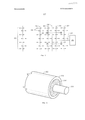
На фиг. 1 показан схематический вид варианта осуществления участка системы термической обработки, предназначенной для обработки пласта, содержащего углеводороды.In FIG. 1 is a schematic view of an embodiment of a portion of a heat treatment system for treating a hydrocarbon containing formation.
На фиг. 2 показан вариант осуществления источника тепла с изолированным проводником.In FIG. 2 shows an embodiment of a heat source with an insulated conductor.
На фиг. 3 показан вариант осуществления источника тепла с изолированным проводником.In FIG. 3 shows an embodiment of a heat source with an insulated conductor.
На фиг. 4 показан вариант осуществления источника тепла с изолированным проводником.In FIG. 4 shows an embodiment of an insulated conductor heat source.
На фиг. 5А и 5В изображены сечения варианта осуществления компонента нагревателя с ограничением рабочих температур, используемого в нагревателе с изолированным проводником.In FIG. 5A and 5B are sectional views of an embodiment of a temperature limited heater component used in an insulated conductor heater.
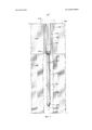
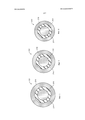
На фиг. 6 изображено сечение варианта осуществления подверженного предварительной холодной обработке и предварительной термообработке изолированного проводника.In FIG. 6 is a cross-sectional view of an embodiment subject to cold pretreatment and pretreatment of an insulated conductor.
На фиг. 7 изображено сечение варианта осуществления, показанного на фиг. 6, после холодной обработки и термообработки.In FIG. 7 is a sectional view of the embodiment shown in FIG. 6, after cold processing and heat treatment.
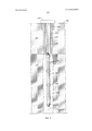
На фиг. 8 изображено сечение варианта осуществления, показанного на фиг. 7, после холодной обработки.In FIG. 8 is a sectional view of the embodiment shown in FIG. 7, after cold working.
На фиг. 9 показан вариант осуществления процесса изготовления изолированного проводника с использованием порошка электрического изолятора.In FIG. 9 shows an embodiment of an insulated conductor manufacturing process using an electrical insulator powder.
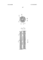
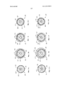
На фиг. 10A изображено сечение первого варианта конструкции материала первой оболочки внутри изолированного проводника.In FIG. 10A is a cross-sectional view of a first embodiment of a material of a first sheath inside an insulated conductor.
На фиг. 10B изображено сечение первого варианта конструкции материала второй оболочки, выполненной в виде трубки и приваренной вокруг материала первой оболочки.In FIG. 10B is a cross-sectional view of a first embodiment of a second shell material made in the form of a tube and welded around a first shell material.
На фиг. 10C изображено сечение первого варианта конструкции материала второй оболочки, выполненной в виде трубки вокруг материала первой оболочки после некоторого сокращения.In FIG. 10C is a cross-sectional view of a first embodiment of a material of the second shell made in the form of a tube around the material of the first shell after some reduction.
На фиг. 10D изображено сечение первого варианта конструкции, когда изолированный проводник проходит через завершающий этап сокращения на вальцовочных роликах.In FIG. 10D is a cross-sectional view of the first embodiment when the insulated conductor passes through the final reduction step on the rolling rollers.
На фиг. 11A изображено сечение второго варианта конструкции материала первой оболочки внутри изолированного проводника.In FIG. 11A is a sectional view of a second embodiment of a material of a first sheath inside an insulated conductor.
На фиг. 11B изображено сечение второго варианта конструкции материала второй оболочки, выполненной в виде трубки и приваренной вокруг материала первой оболочки.In FIG. 11B is a sectional view of a second embodiment of the material of the second shell made in the form of a tube and welded around the material of the first shell.
На фиг. 11C изображено сечение второго варианта конструкции материала второй оболочки, выполненной в виде трубки вокруг материала первой оболочки после некоторого сокращения.In FIG. 11C is a sectional view of a second embodiment of the material of the second shell made in the form of a tube around the material of the first shell after some reduction.
На фиг. 11D изображено сечение второго варианта конструкции, когда изолированный проводник проходит через завершающий этап сокращения на вальцовочных роликах.In FIG. 11D is a sectional view of a second embodiment when the insulated conductor passes through the final reduction step on the rolling rollers.
Хотя в изобретение допускает различные модификации и альтернативные формы, отдельные варианты его осуществления показаны на чертежах в качестве примера и будут описаны подробно. Чертежи могут не быть выполненными в масштабе. Следует понимать, что не предполагается, что чертежи и подробное описание ограничивают изобретение конкретной описанной формой, а наоборот, предполагается, что оно покрывает все модификации, эквиваленты и альтернативы, попадающие под сущность и объем настоящего изобретения, как задано прилагаемой формулой определения.Although the invention allows various modifications and alternative forms, individual embodiments thereof are shown in the drawings by way of example and will be described in detail. Drawings may not be made to scale. It should be understood that the drawings and detailed description are not intended to limit the invention to the particular form described, but rather, it is intended to cover all modifications, equivalents, and alternatives that fall within the spirit and scope of the present invention as defined by the appended claims.
Осуществление изобретенияThe implementation of the invention
Нижеследующее описание, в целом, относится к системам и способам обработки углеводородов в пластах. Такие пласты могут быть обработаны для добычи углеводородных продуктов, водорода и других продуктов.The following description generally relates to systems and methods for treating hydrocarbons in formations. Such formations can be processed to produce hydrocarbon products, hydrogen, and other products.
Выражение "переменный ток (AC)" означает изменяющийся во времени ток, который меняет направление по существу синусоидально. Переменный ток производит поверхностный эффект в ферромагнитном проводнике.The expression "alternating current (AC)" means a time-varying current that changes direction essentially sinusoidally. Alternating current produces a surface effect in a ferromagnetic conductor.
В контексте нагревательных систем со сниженной теплоотдачей, устройств и способов, термин "автоматически" означает определенное функционирование систем, устройств и способов без использования внешних органов управления (например, внешних контроллеров, таких как контроллер с датчиком температуры и обратной связью, ПИД-регулятор или предсказывающий контроллер).In the context of reduced heat transfer heating systems, devices and methods, the term “automatically” means the specific operation of systems, devices and methods without using external controls (eg, external controllers, such as a controller with a temperature sensor and feedback, a PID controller or predictive controller).
Термин "соединенный" означает либо непосредственное соединение, либо непрямое соединение (например, одно или несколько промежуточных соединений) между одним или несколькими объектами или компонентами. Фраза "непосредственно соединенный" означает непосредственное соединение между объектами или компонентами, так что объекты или компоненты соединены непосредственно друг с другом, так что объекты или компоненты функционируют "в месте использования".The term “connected” means either a direct connection or an indirect connection (for example, one or more intermediate compounds) between one or more objects or components. The phrase "directly connected" means a direct connection between objects or components, so that the objects or components are connected directly to each other, so that the objects or components function "in place of use."
"Температура Кюри" - это температура, выше которой ферромагнитный материал теряет все свои ферромагнитные свойства. В дополнение к потере всех своих ферромагнитных свойств, при температуре выше температуры Кюри ферромагнитный материал начинает терять свои ферромагнитные свойства, когда через ферромагнитный материал проводят увеличивающийся электрический ток."Curie temperature" is the temperature above which a ferromagnetic material loses all of its ferromagnetic properties. In addition to losing all of its ferromagnetic properties, at temperatures above the Curie temperature, the ferromagnetic material begins to lose its ferromagnetic properties when an increasing electric current is passed through the ferromagnetic material.
Термин "пласт" включает в себя один или несколько содержащих углеводороды слоев, один или несколько неуглеводородных слоев, перекрывающих и/или подстилающих. Выражение "углеводородные слои" относится к слоям в пласте, которые содержат углеводороды. Углеводородные слои могут содержать неуглеводородный материал и углеводородный материал. Термины "перекрывающая порода" и/или "подстилающая порода" включают в себя один или несколько различных типов непроницаемых материалов. Например, перекрывающая и/или подстилающая порода может включать в себя скальную породу, сланец, аргиллит или влажную/плотную карбонатную породу. В некоторых вариантах осуществления в процессах термообработки пласта перекрывающая и/или подстилающая порода может включать в себя слои, содержащие углеводороды, или слои, не содержащие углеводороды, которые являются сравнительно непроницаемыми и не подвергаются воздействию температуры во время процесса термообработки пласта, что приводит к значительным изменениям характеристик слоев, содержащих углеводороды, перекрывающей и/или подстилающей породы. Например, подстилающая порода может содержать сланец или аргиллит, но во время термообработки пласта не допускается нагрев подстилающей породы до температур пиролиза. В некоторых случаях перекрывающая порода и/или подстилающая порода могут быть в какой-то степени проницаемыми.The term "formation" includes one or more hydrocarbon-containing layers, one or more non-hydrocarbon layers, overlapping and / or underlying. The term “hydrocarbon layers” refers to layers in a formation that contain hydrocarbons. The hydrocarbon layers may contain non-hydrocarbon material and hydrocarbon material. The terms "overburden" and / or "bedrock" include one or more different types of impermeable materials. For example, the overburden and / or bedrock may include rock, shale, mudstone, or wet / dense carbonate. In some embodiments, in formation heat treatment processes, the overburden and / or bedrock may include hydrocarbon containing layers or hydrocarbon-free layers that are relatively impermeable and not exposed to temperature during the formation heat treatment process, resulting in significant changes the characteristics of the layers containing hydrocarbons, overlapping and / or underlying rocks. For example, the underlying rock may contain shale or mudstone, but during the heat treatment of the formation is not allowed to heat the underlying rock to pyrolysis temperatures. In some cases, the overburden and / or bedrock may be somewhat permeable.
Выражение "пластовый флюид" означает текучие среды, присутствующие в пласте, и могут включать в себя текучие среды пиролиза, синтез-газ, подвижные углеводороды и воду (пар). Пластовые флюиды могут включать в себя углеводородные флюиды, а также неуглеводородные флюиды. Термин "подвижные флюиды" означает флюиды в пласте, содержащем углеводороды, которые могут перетекать в результате термообработки пласта. Термин "добываемые флюиды" относится к флюидам, извлекаемым из пласта.The expression “formation fluid” means fluids present in the formation and may include pyrolysis fluids, synthesis gas, mobile hydrocarbons and water (steam). Formation fluids may include hydrocarbon fluids as well as non-hydrocarbon fluids. The term “moving fluids” means fluids in a formation containing hydrocarbons that may flow as a result of heat treatment of the formation. The term "produced fluids" refers to fluids recovered from the formation.
"Тепловой поток" - это поток энергии на единицу площади в единицу времени (например, Вт/м2).A "heat flux" is a flux of energy per unit area per unit time (for example, W / m 2 ).
Выражение "источник тепла" представляет собой любую систему для подачи тепла, по меньшей мере, на участок пласта по существу с помощью кондуктивной/лучистой теплопередачи. Например, источник тепла может включать в себя электропроводные материалы и/или электронагреватели, такие как изолированный проводник, вытянутый элемент и/или проводник, расположенные в канале. Источник тепла также может включать в себя системы, которые вырабатывают теплоту путем сжигания топлива, являющегося внешними по отношению к пласту, или находящегося в пласте. Системы могут представлять собой поверхностные горелки, скважинные газовые горелки, беспламенные распределенные камеры сгорания и природные распределенные камеры сгорания. В некоторых вариантах осуществления тепло, подаваемое или вырабатываемое в одном или нескольких источниках тепла, может снабжаться другими источниками энергии. Другие источники энергии могут непосредственно нагревать пласт, либо энергия может передаваться на передающую среду, которая непосредственно или косвенно нагревает пласт. Следует понимать, что один или несколько источников тепла, которые подводят тепло к пласту, используют различные источники энергии. Таким образом, например, для данного пласта некоторые источники тепла могут подавать тепло от электропроводных материалов, резистивных электронагревателей, некоторые источники тепла могут подавать тепло от процесса горения, а некоторые источники тепла могут подавать тепло от одного или нескольких других источников энергии (например, от химических реакций, солнечную энергию, энергию ветра, биомассы или других источников возобновляемой энергии). Химическая реакция может включать в себя экзотермическую реакцию (например, реакцию окисления). Источник тепла также может включать в себя электропроводный материал и/или нагреватель, который подает тепло в зону, расположенную возле и/или окружающую место нагревания, такую как нагревательная скважина.The term “heat source” is any system for delivering heat to at least a portion of a formation using substantially conductive / radiant heat transfer. For example, a heat source may include electrically conductive materials and / or electric heaters, such as an insulated conductor, an elongated element, and / or a conductor located in the channel. The heat source may also include systems that generate heat by burning fuel that is external to or in the formation. Systems can be surface burners, downhole gas burners, flameless distributed combustion chambers, and natural distributed combustion chambers. In some embodiments, heat supplied or generated in one or more heat sources may be provided with other energy sources. Other energy sources can directly heat the formation, or energy can be transferred to a transmission medium that directly or indirectly heats the formation. It should be understood that one or more heat sources that supply heat to the formation use different energy sources. Thus, for example, for a given formation, some heat sources can supply heat from electrically conductive materials, resistive electric heaters, some heat sources can supply heat from the combustion process, and some heat sources can supply heat from one or more other energy sources (for example, from chemical reactions, solar energy, wind energy, biomass or other sources of renewable energy). A chemical reaction may include an exothermic reaction (e.g., an oxidation reaction). The heat source may also include an electrically conductive material and / or a heater that supplies heat to an area adjacent to and / or surrounding a heating location, such as a heating well.
"Нагреватель" - это любая система или источник тепла, предназначенный для выработки теплоты в скважине или в области возле скважины. Нагреватели могут представлять собой электронагреватели, горелки, камеры сгорания, которые осуществляют реакцию с веществом, расположенным или добываемым из пласта, и/или их сочетания, но, не ограничиваясь этим.A “heater” is any system or heat source designed to generate heat in a well or in an area near a well. Heaters can be electric heaters, burners, combustion chambers that react with a substance located or mined from the formation, and / or combinations thereof, but not limited to.
"Углеводороды", в общем, определяют как молекулы, образованные преимущественно из атомов углерода и водорода. Углеводороды также могут включать в себя другие элементы, такие как галогены, металлические элементы, азот, кислород и/или сера, но, не ограничиваясь этим. Углеводороды могут представлять собой кероген, битум, пиробитум, масла, природные минеральные воски и асфальтиты. Углеводороды могут быть расположены в скелетных породах в земле или примыкать к ним. Скелетные породы включают в себя осадочные породы, пески, силицилиты, карбонаты, диатомиты и другие пористые среды, но, не ограничиваясь этим. "Углеводородные флюиды" представляют собой флюиды, содержащие углеводороды. Углеводородные флюиды могут включать в себя, охватывать или быть охваченными неуглеводородными флюидами, такими как водород, азот, окись углерода, двуокись углерода, сероводород, вода и аммиак.“Hydrocarbons” are generally defined as molecules formed predominantly from carbon and hydrogen atoms. Hydrocarbons may also include other elements, such as, but not limited to, halogens, metal elements, nitrogen, oxygen and / or sulfur. Hydrocarbons can be kerogen, bitumen, pyrobitumen, oils, natural mineral waxes and asphalts. Hydrocarbons can be located in skeletal rocks in the earth or adjacent to them. Skeletal rocks include, but are not limited to, sedimentary rocks, sands, silicites, carbonates, diatomites, and other porous media. "Hydrocarbon fluids" are fluids containing hydrocarbons. Hydrocarbon fluids may include, cover, or be covered by non-hydrocarbon fluids such as hydrogen, nitrogen, carbon monoxide, carbon dioxide, hydrogen sulfide, water, and ammonia.
Выражение "процесс преобразования в пласте" относится к процессу нагревания пласта, содержащего углеводороды, с помощью источников тепла, чтобы поднять температуру, по меньшей мере, части пласта до температуры, превышающей температуру пиролиза, чтобы в пласте образовывался пиролизный флюид.The term “formation conversion process” refers to the process of heating a hydrocarbon containing formation using heat sources to raise the temperature of at least a portion of the formation to a temperature above the pyrolysis temperature so that pyrolysis fluid is generated in the formation.
Выражение "процесс термообработки в пласте" относится к процессу нагревания пласта, содержащего углеводороды, с помощью источников тепла, чтобы поднять температуру, по меньшей мере, части пласта до температуры, превышающей температуру, при которой возникает подвижный флюид, висбрекинг и/или пиролиз материала, содержащего углеводороды, чтобы в пласте образовывались подвижные флюиды, флюиды висбрекинга и/или пиролизные флюиды.The expression “heat treatment process in the formation” refers to the process of heating a hydrocarbon containing formation using heat sources to raise the temperature of at least a portion of the formation to a temperature higher than the temperature at which mobile fluid, visbreaking and / or pyrolysis of the material occurs, containing hydrocarbons so that mobile fluids, visbreaking fluids and / or pyrolysis fluids are formed in the formation.
Термин "изолированный проводник" означает любой вытянутый материал, который способен проводить электричество и который полностью или частично покрыт электроизоляционным материалом.The term "insulated conductor" means any elongated material that is capable of conducting electricity and which is fully or partially coated with an insulating material.
Выражение "модулированный постоянный ток (DC)" относится к любому по существу не синусоидальному изменяющемуся во времени току, который производит скин-эффект электрического тока в ферромагнитном проводнике.The term "modulated direct current (DC)" refers to any substantially non-sinusoidal time-varying current that produces the skin effect of an electric current in a ferromagnetic conductor.
Термин "нитрид" означает соединение азота и одного или нескольких других элементов периодической таблицы. Нитриды включают в себя нитрид кремния, нитрид бора или глинозем, но, не ограничиваясь этим.The term "nitride" means a compound of nitrogen and one or more other elements of the periodic table. Nitrides include, but are not limited to, silicon nitride, boron nitride, or alumina.
Термин "отверстия" включает в себя отверстия, прорези, проемы или дырки в стенке канала, трубы, трубопровода или другой направляющей потока, которые позволяют втекать или вытекать из канала, трубы, трубопровода или другой направляющей потока.The term “openings” includes openings, slots, openings or holes in a wall of a channel, pipe, conduit or other flow guide that allows flow in or out of a channel, pipe, conduit or other flow guide.
"Температура фазового превращения" ферромагнитного материала - это температура или диапазон температур, при которых материал подвергается фазовому переходу (например, из феррита переходит в аустенит), который увеличивает магнитную проницаемость ферромагнитного материала. Сокращение магнитной проницаемости аналогично сокращению магнитной проницаемости из-за магнитного перехода ферромагнитного материала при температуре Кюри.The “phase transformation temperature" of a ferromagnetic material is the temperature or temperature range at which the material undergoes a phase transition (for example, it transforms from ferrite to austenite), which increases the magnetic permeability of the ferromagnetic material. The reduction in magnetic permeability is similar to the reduction in magnetic permeability due to the magnetic transition of the ferromagnetic material at the Curie temperature.
"Пиролиз" представляет собой разрыв химических связей под действием прикладываемого тепла. Например, пиролиз может включать в себя преобразование соединения в одну или несколько других субстанций только под воздействием тепла. Тепло может быть передано к участку пласта для того, чтобы возник пиролиз."Pyrolysis" is the breaking of chemical bonds under the influence of applied heat. For example, pyrolysis may include converting the compound into one or more other substances only when exposed to heat. Heat can be transferred to the area of the formation so that pyrolysis occurs.
"Пиролизные флюиды" или "продукты пиролиза" относятся к флюидам, полученным по существу во время процесса пиролиза углеводородов. Флюиды, полученные при реакциях пиролиза, могут смешиваться с другими флюидами в пласте. Смесь можно рассматривать в качестве пиролизного флюида или продукта пиролиза. Используемый в этом документе термин "зона пиролиза" относится к объему пласта (например, сравнительно проницаемого пласта, такого как пласт нефтеносных песков), который подвергают реакции, или в котором происходит реакция для образования пиролизного флюида."Pyrolysis fluids" or "pyrolysis products" refer to fluids obtained substantially during the pyrolysis of hydrocarbons. Fluids obtained from pyrolysis reactions can mix with other fluids in the formation. The mixture can be considered as a pyrolysis fluid or a pyrolysis product. As used herein, the term “pyrolysis zone” refers to the volume of a formation (eg, a relatively permeable formation, such as oil sands) that is being reacted or in which a reaction takes place to form a pyrolysis fluid.
Выражение "суперпозиция тепла" относится к подаче тепла от двух или нескольких источников тепла в выбранный участок пласта, так что на температуру пласта, по меньшей мере, в одном месте между источниками тепла влияют источники тепла.The expression "superposition of heat" refers to the supply of heat from two or more heat sources to a selected area of the formation, so that heat sources influence the temperature of the formation at least in one place between the heat sources.
"Нагреватель с ограничением рабочих температур", в целом, представляет собой нагреватель, который регулирует теплоотдачу (например, снижает теплоотдачу) при температуре, превышающей заданную, без использования внешних органов управления, таких как контроллеры температуры, регуляторы мощности, ректификаторы или другие устройства. Нагреватели с ограничением рабочих температур могут представлять собой электрические резистивные нагреватели, работающие от переменного тока (AC) или модулированного (например, "ограниченного") постоянного тока (DC).A "temperature limited heater" is generally a heater that controls heat transfer (for example, reduces heat transfer) at a temperature exceeding a predetermined one without the use of external controls such as temperature controllers, power controllers, rectifiers or other devices. Temperature limited heaters may be electric resistive heaters operating on alternating current (AC) or modulated (eg, "limited") direct current (DC).
"Толщина" слоя означает толщину поперечного сечения слоя, причем поперечное сечение проходит по нормали к поверхности слоя.“Thickness” of a layer means the thickness of the cross section of the layer, the cross section extending normal to the surface of the layer.
"Изменяющийся со временем ток" означает электрический ток, который производит скин-эффект электрического тока в ферромагнитном проводнике, и амплитуда которого меняется со временем. Изменяющийся со временем ток включает в себя и переменный ток (AC), и модулированный постоянный ток (DC)."Current changing with time" means an electric current that produces the skin effect of an electric current in a ferromagnetic conductor, and whose amplitude varies with time. The current that changes over time includes both alternating current (AC) and modulated direct current (DC).
"Динамический диапазон" для нагревателя с ограничением рабочих температур, в котором ток проводят непосредственно по нагревателю, представляет собой отношение самого высокого сопротивления по переменному току или модулированному постоянному току при температуре ниже температуры Кюри к самому низкому сопротивлению по переменному току или модулированному постоянному току при температуре выше температуры Кюри для заданного значения тока. Динамический диапазон для индуктивного нагревателя представляет собой отношение наивысшей теплоотдачи при температуре ниже температуры Кюри к самой низкой теплоотдаче при температуре выше температуры Кюри для заданного значения тока, проводимого через нагреватель.The "dynamic range" for a temperature limited heater in which current is conducted directly through the heater is the ratio of the highest AC resistance or modulated DC current at a temperature below the Curie temperature to the lowest AC resistance or modulated DC current at a temperature above the Curie temperature for a given current value. The dynamic range for an inductive heater is the ratio of the highest heat transfer at a temperature below the Curie temperature to the lowest heat transfer at a temperature above the Curie temperature for a given value of the current conducted through the heater.
"U-образная скважина" представляет собой скважину, которая идет от первого отверстия в пласте, проходит через, по меньшей мере, часть пласта и выходит через второе отверстие в пласте. В этом контексте скважина может иметь форму в виде буквы "v" или "u" только в грубом приближении, при этом надо понимать, что, чтобы рассматривать скважину в качестве "u-образной", "ножки" буквы "u" не обязательно должны быть параллельными друг относительно друга или перпендикулярными "дну" буквы "u".A “U-shaped well” is a well that extends from a first hole in a formation, passes through at least a portion of the formation, and exits through a second hole in the formation. In this context, the well can take the form of the letter “v” or “u” only in a rough approximation, and it should be understood that in order to consider the well as “u-shaped”, the “legs” of the letter “u” do not have to be parallel to each other or perpendicular to the "bottom" of the letter "u".
Термин "скважина" обозначает отверстие в пласте, выполненное посредством бурения или вставки трубы в пласт. Скважина может иметь по существу круглое поперечное сечение или другую форму поперечного сечения. Используемые в этом документе термины "колодец" и "отверстие" в контексте отверстия в пласте могут быть взаимозаменяемыми с термином "скважина".The term “well” means a hole in a formation made by drilling or inserting a pipe into the formation. The well may have a substantially circular cross section or other cross sectional shape. As used herein, the terms “well” and “hole” in the context of a hole in a formation may be used interchangeably with the term “well”.
Чтобы получить разные продукты, пласт может быть подвергнут обработке различными способами. Для обработки пласта во время процесса термообработки могут использоваться различные этапы или процессы. В некоторых вариантах осуществления один или несколько участков пласта разрабатывают растворением, чтобы удалить растворимые минералы из участков. Добываемые растворением минералы могут быть произведены до, во время и/или после процесса термообработки пласта. В некоторых вариантах осуществления средняя температура одного или нескольких участков, добычу из которых осуществляют растворением, может поддерживаться ниже примерно 120°C.To obtain different products, the formation can be processed in various ways. Various stages or processes can be used to treat the formation during the heat treatment process. In some embodiments, one or more portions of the formation is developed by dissolution to remove soluble minerals from the sites. Minerals produced by dissolution can be produced before, during, and / or after the heat treatment of the formation. In some embodiments, the implementation of the average temperature of one or more areas, the extraction of which is carried out by dissolution, can be maintained below about 120 ° C.
В некоторых вариантах осуществления один или несколько участков пласта нагревают, чтобы удалить воду из участков и/или чтобы удалить метан и другие летучие углеводороды из участков. В некоторых вариантах осуществления в процессе удаления воды и летучих углеводородов средняя температура может быть поднята от температуры окружающей среды до температур ниже примерно 220°C.In some embodiments, one or more portions of the formation is heated to remove water from the sites and / or to remove methane and other volatile hydrocarbons from the sites. In some embodiments, during the process of removing water and volatile hydrocarbons, the average temperature may be raised from ambient temperature to temperatures below about 220 ° C.
В некоторых вариантах осуществления один или несколько участков пласта нагревают до температур, которые допускают перемещение и/или висбрекинг углеводородов в пласте. В некоторых вариантах осуществления средняя температура одного или нескольких участков пласта может быть поднята до температур активации углеводородов в участках (например, до температур из диапазона от 100°C до 250°C, от 120°C до 240°C или от 150°C до 230°C).In some embodiments, one or more portions of the formation is heated to temperatures that allow movement and / or visbreaking of hydrocarbons in the formation. In some embodiments, the average temperature of one or more sections of the formation may be raised to the activation temperatures of hydrocarbons in the areas (for example, temperatures from a range of 100 ° C to 250 ° C, 120 ° C to 240 ° C, or 150 ° C to 230 ° C).
В некоторых вариантах осуществления один или несколько участков нагревают до температур, которые допускают реакции пиролиза в пласте. В некоторых вариантах осуществления средняя температура одного или нескольких участков пласта может быть поднята до температур пиролиза углеводородов в участках (например, до температур из диапазона от 230°C до 900°C, от 240°C до 400°C или от 250°C до 350°C).In some embodiments, one or more sections are heated to temperatures that allow for pyrolysis reactions in the formation. In some embodiments, the average temperature of one or more sections of the formation may be raised to the pyrolysis temperatures of hydrocarbons in the areas (for example, temperatures from a range of 230 ° C to 900 ° C, 240 ° C to 400 ° C, or 250 ° C to 350 ° C).
Нагревание пласта, содержащего углеводороды, с помощью нескольких источников тепла может установить термические градиенты вокруг источников тепла, которые поднимают температуру углеводородов в пласте до желаемых температур с желаемыми скоростями нагрева. Скорость увеличения температуры через диапазон температур активации и/или диапазон температур пиролиза для желаемых продуктов может повлиять на качество и количество пластовых флюидов, получаемых из пласта, содержащего углеводороды. Медленно поднимая температуру пласта через диапазон температур активации и/или диапазон температур пиролиза, можно допустить получение из пласта углеводородов высокого качества, высокой плотности. Медленно поднимая температуру пласта через диапазон температур активации и/или диапазон температур пиролиза, можно позволить извлечь большое количество углеводородов, присутствующих в пласте в качестве углеводородного продукта.Heating a hydrocarbon containing formation using multiple heat sources can establish thermal gradients around heat sources that raise the temperature of the hydrocarbons in the formation to desired temperatures with desired heating rates. The rate of temperature increase through the range of activation temperatures and / or the range of pyrolysis temperatures for the desired products may affect the quality and quantity of formation fluids obtained from the formation containing hydrocarbons. Slowly raising the formation temperature through the activation temperature range and / or the pyrolysis temperature range, it is possible to obtain high-quality, high-density hydrocarbons from the formation. By slowly raising the formation temperature through the activation temperature range and / or the pyrolysis temperature range, it is possible to recover a large amount of hydrocarbons present in the formation as a hydrocarbon product.
В некоторых вариантах осуществления термообработки пласта участок пласта нагревают до желаемой температуры вместо медленного нагрева через диапазон температур. В некоторых вариантах осуществления желаемая температура составляет 300°C, 325°C или 350°C. В качестве желаемой температуры можно выбрать другое значение.In some embodiments of a heat treatment of a formation, a portion of the formation is heated to a desired temperature instead of slowly heating through a temperature range. In some embodiments, the desired temperature is 300 ° C, 325 ° C, or 350 ° C. You can select a different value as the desired temperature.
Суперпозиция теплоты от источников тепла позволяет установить в пласте желаемую температуру сравнительно быстро и эффективно. Подводимая в пласт энергия от источников тепла может быть отрегулирована так, чтобы поддерживать в пласте по существу желаемую температуру.The superposition of heat from heat sources allows you to set the desired temperature in the formation relatively quickly and efficiently. The energy supplied to the formation from heat sources can be adjusted to maintain a substantially desired temperature in the formation.
Продукты активации и/или пиролиза могут быть получены из пласта через эксплуатационные скважины. В некоторых вариантах осуществления среднюю температуру одного или нескольких участков поднимают до температур активации, и из эксплуатационных скважин получают углеводороды. Средняя температура одного или нескольких участков может быть поднята до температур пиролиза после того, как выход из-за активации опустится ниже выбранного значения. В некоторых вариантах осуществления средняя температура одного или нескольких участков может быть поднята до температур пиролиза без значительного выхода до достижения температур пиролиза. Пластовые флюиды, включая продукты пиролиза, могут быть получены через эксплуатационные скважины.Activation and / or pyrolysis products can be obtained from the formation through production wells. In some embodiments, the average temperature of one or more sites is raised to activation temperatures, and hydrocarbons are produced from production wells. The average temperature of one or more sections can be raised to pyrolysis temperatures after the output due to activation drops below the selected value. In some embodiments, the average temperature of one or more sections can be raised to pyrolysis temperatures without significant yield until pyrolysis temperatures are reached. Formation fluids, including pyrolysis products, can be obtained through production wells.
В некоторых вариантах осуществления средняя температура одного или нескольких участков может быть поднята до температур достаточных для того, чтобы после активации и пиролиза допустить выход синтез-газа. В некоторых вариантах осуществления, углеводороды могут быть нагреты до температур, достаточных для того, чтобы допустить выход синтез-газа без значительного выхода до достижения температур, достаточных для того, чтобы допустить выход синтез-газа. Например, синтез-газ может быть получен в диапазоне температур примерно от 400°C до 1200°C, от 500°C до 1100°C или от 550°C до 1000°C. Текучая среда, вырабатывающая синтез-газ (например, пар и/или вода) может быть введена в участки для выработки синтез-газа. Синтез-газ может быть получен из эксплуатационных скважин.In some embodiments, the average temperature of one or more sites can be raised to temperatures sufficient to allow synthesis gas to escape after activation and pyrolysis. In some embodiments, the hydrocarbons may be heated to temperatures sufficient to allow the synthesis gas to exit without significant output until temperatures are sufficient to allow the synthesis gas to exit. For example, synthesis gas can be obtained in a temperature range of from about 400 ° C to 1200 ° C, from 500 ° C to 1100 ° C, or from 550 ° C to 1000 ° C. A synthesis gas generating fluid (e.g., steam and / or water) may be introduced into the synthesis gas generating sections. Synthesis gas can be obtained from production wells.
Добыча растворением, извлечение летучих углеводородов и воды, активация углеводородов, пиролиз углеводородов, выработка синтез-газа и/или другие процессы могут быть выполнены во время процесса термообработки пласта. В некоторых вариантах осуществления некоторые процессы могут быть выполнены после процесса термообработки пласта. Такие процессы могут включать в себя восстановление тепла от обработанных участков, сохранение текучих сред (например, воды и/или углеводородов) в ранее обработанных участках и/или отделение диокиси углерода в ранее обработанных участках.Dissolution mining, volatile hydrocarbon and water recovery, hydrocarbon activation, hydrocarbon pyrolysis, synthesis gas generation and / or other processes can be performed during the heat treatment of the formation. In some embodiments, some processes may be performed after the heat treatment of the formation. Such processes may include recovering heat from treated areas, retaining fluids (e.g., water and / or hydrocarbons) in previously treated areas, and / or separating carbon dioxide in previously treated areas.
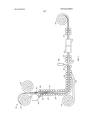
На фиг. 1 показан схематический вид варианта осуществления участка системы термической обработки, предназначенной для обработки пласта, содержащего углеводороды. Система термической обработки пласта может включать в себя барьерные скважины 200. Барьерные скважины используют для того, чтобы образовать барьер вокруг обрабатываемой области. Барьер препятствует потоку флюидов в и/или из обрабатываемой области. Барьерная скважина включает в себя водопонижающие скважины, вакуумные скважины, захватывающие скважины, нагнетательные скважины, цементирующие скважины, морозильные скважины и их сочетания, но, не ограничиваясь этим. В некоторых вариантах осуществления барьерные скважины 200 представляют собой водопонижающие скважины. Водопонижающие скважины могут удалять жидкую воду и/или препятствовать поступлению жидкой воды в участок пласта, который надо нагреть, или в нагреваемый пласт. В варианте осуществления, показанном на фиг. 1, барьерные скважины 200 показаны проходящими только вдоль одной стороны источников 202 тепла, но барьерные скважины обычно окружают все используемые источники 202 тепла или источники, которые надо использовать, чтобы нагреть обрабатываемую область пласта.In FIG. 1 is a schematic view of an embodiment of a portion of a heat treatment system for treating a hydrocarbon containing formation. The heat treatment system of the formation may include
Источники 202 тепла размещают, по меньшей мере, в части пласта. Источники 202 тепла могут включать в себя нагреватели, такие как изолированные проводники, нагреватели с проводником в канале, поверхностные горелки, беспламенные распределенные камеры сгорания и/или природные распределенные камеры сгорания. Источники 202 тепла также могут включать в себя другие типы нагревателей. Источники 202 тепла подают тепло, по меньшей мере, в часть пласта, чтобы нагреть углеводороды в пласте. Энергия может подаваться к источникам 202 тепла через линии 204 питания. Лини 204 питания могут структурно отличаться, в зависимости от типа источника тепла или источников тепла, используемых для нагрева пласта. Линии 204 питания для источников тепла могут передавать электричество для электронагревателей, топливо для камер сгорания, или могут передавать теплообменную текучую среду, которая циркулирует в пласте. В некоторых вариантах осуществления электричество для процесса термообработки пласта может обеспечиваться атомной электростанцией или атомными электростанциями. Использование атомной энергии может позволить сократить или ограничить выбросы окиси углерода в процессе термообработки пласта.
Когда пласт нагревают, поступление тепла в пласт может вызвать расширение пласта и геомеханическое перемещение. Источники тепла могут быть включены до, вместе или во время процесса обезвоживания. Реакцию пласта на нагрев можно смоделировать посредством компьютерной симуляции. Компьютерная симуляция может быть использована для разработки шаблона и последовательности активизации источников тепла в пласте так, чтобы геомеханическое перемещение пласта не оказало неблагоприятного воздействия на функциональность источников тепла, эксплуатационных скважин и другого оборудования в пласте.When the formation is heated, the entry of heat into the formation can cause expansion of the formation and geomechanical movement. Heat sources may be included before, together with, or during the dehydration process. The response of the formation to heat can be modeled by computer simulation. Computer simulation can be used to develop a pattern and sequence of activation of heat sources in the formation so that the geomechanical movement of the formation does not adversely affect the functionality of heat sources, production wells and other equipment in the formation.
Нагрев пласта может привести к увеличению проницаемости и/или пористости пласта. Увеличение проницаемости и/или пористости может привести к сокращению массы в пласте из-за испарения и удаления воды, удаления углеводородов и/или возникновения трещин. Текучая среда может легко течь в нагретый участок пласта, благодаря увеличенной проницаемости и/или пористости пласта. Благодаря увеличенной проницаемости и/или пористости пласта, текучая среда в нагретом участке пласта может перемещаться на значительное расстояние через пласт. Значительное расстояние может превышать 1000 м, в зависимости от различных факторов, таких как проницаемость пласта, свойства текучей среды, температура пласта и градиент давления, допускающий перемещение текучей среды. Способность текучей среды перемещаться на значительное расстояние в пласте позволяет расположить эксплуатационные скважины 206 сравнительно далеко от пласта.Heating the formation can lead to an increase in permeability and / or porosity of the formation. An increase in permeability and / or porosity can lead to a reduction in mass in the formation due to evaporation and removal of water, removal of hydrocarbons and / or cracking. Fluid can easily flow into a heated portion of the formation due to increased permeability and / or porosity of the formation. Due to the increased permeability and / or porosity of the formation, the fluid in the heated portion of the formation can travel a considerable distance through the formation. A considerable distance can exceed 1000 m, depending on various factors, such as formation permeability, fluid properties, formation temperature, and pressure gradient allowing fluid to move. The ability of the fluid to travel a considerable distance in the formation allows
Эксплуатационные скважины 206 используют для извлечения пластового флюида из пласта. В некоторых вариантах осуществления эксплуатационная скважина 206 включает в себя источник тепла. Источник тепла в эксплуатационной скважине может нагревать один или несколько участков пласта в эксплуатационной скважине или рядом с ней. В некоторых вариантах осуществления процесса термообработки пласта количество теплоты, подаваемой в пласт от эксплуатационной скважины на метр эксплуатационной скважины, меньше, чем количество теплоты, подаваемой в пласт от источника тепла, который нагревает пласт, на метр источника тепла. Теплота, подаваемая в пласт от эксплуатационной скважины, может увеличить проницаемость пласта возле эксплуатационной скважины посредством испарения и удаления флюида жидкой фазы возле эксплуатационной скважины и/или путем увеличения проницаемости пласта возле эксплуатационной скважины из-за формирования макро и/или микротрещин.
В эксплуатационной скважине может быть расположено более одного источника тепла. Источник тепла в нижнем участке эксплуатационной скважины может быть выключен, если суперпозиция теплоты от смежных источников тепла нагревает пласт достаточно, чтобы нейтрализовать преимущества, обеспечиваемые нагревом пласта от эксплуатационной скважины. В некоторых вариантах осуществления источник тепла в верхнем участке эксплуатационной скважины может оставаться включенным после выключения источника тепла в нижнем участке эксплуатационной скважины. Источник тепла в верхнем участке скважины может препятствовать конденсации и обратному стоку пластового флюида.A production well may have more than one heat source. The heat source in the lower section of the production well can be turned off if a superposition of heat from adjacent heat sources heats the formation enough to neutralize the benefits of heating the formation from the production well. In some embodiments, the heat source in the upper portion of the production well may remain on after the heat source in the lower portion of the production well is turned off. A heat source in the upper portion of the well may impede condensation and backflow of formation fluid.
В некоторых вариантах осуществления источник тепла в эксплуатационной скважине 206 позволяет удалять пластовые флюиды в виде пара из пласта. Обеспечение нагрева в эксплуатационной скважине или через нее может: (1) препятствовать конденсации и/или обратному стоку пластового флюида, если такой пластовый флюид перемещается в эксплуатационной скважине вблизи от перекрывающей породы, (2) увеличить поступление тепла в пласт, (3) увеличить дебит эксплуатационной скважины по сравнению с эксплуатационной скважиной без источника тепла, (4) препятствовать конденсации высокоуглеродистых соединений (C6 углеводородов и более тяжелых) в эксплуатационной скважине и/или (5) увеличить проницаемость пласта в эксплуатационной скважине или возле нее.In some embodiments, a heat source in
Подземное давление в пласте может соответствовать давлению текучей среды, вырабатываемой в пласте. По мере увеличение температур в нагретом участке давление в нагретом участке может увеличиваться в результате теплового расширения присутствующих в нем флюидов, увеличенного образования флюидов и испарения воды. Управляя скоростью удаления флюидов из пласта, можно управлять давлением в пласте. Давление в пласте можно определить во множестве различных мест, например, возле эксплуатационной скважины или в ней, возле или у источников тепла или в контрольных скважинах.The subsurface pressure in the formation may correspond to the pressure of the fluid generated in the formation. As temperatures increase in the heated portion, the pressure in the heated portion may increase as a result of thermal expansion of the fluids present in it, increased formation of fluids, and evaporation of water. By controlling the rate of fluid removal from the formation, it is possible to control the pressure in the formation. The pressure in the formation can be determined in many different places, for example, near or in the production well, near or near heat sources or in control wells.
В некоторых пластах, содержащих углеводороды, препятствуют выходу углеводородов из пласта до тех пор, пока, по меньшей мере, некоторые углеводороды в пласте не будут активированы и/или пиролизованы. Пластовый флюид может быть получен из пласта, когда пластовый флюид обладает выбранным свойством. В некоторых вариантах осуществления выбранное свойство включает в себя плотность в градусах Американского нефтяного института (АНИ), равную, по меньшей мере, 20°, 30° или 40°. Препятствие выходу до тех пор, пока, по меньшей мере, некоторые углеводороды в пласте не будут активированы и/или пиролизованы, может увеличить преобразование тяжелых углеводородов в легкие углеводороды. Препятствие начальному выходу может минимизировать выход тяжелых углеводородов из пласта. Выход существенного количества тяжелых углеводородов может потребовать дорогостоящего оборудования и/или сокращения срока службы производственного оборудования.In some hydrocarbon containing formations, hydrocarbons are prevented from leaving the formation until at least some hydrocarbons in the formation are activated and / or pyrolyzed. Formation fluid may be obtained from the formation when the formation fluid has a selected property. In some embodiments, the selected property includes a density in degrees of the American Petroleum Institute (ANI) of at least 20 °, 30 °, or 40 °. An obstacle to exit until at least some hydrocarbons in the formation are activated and / or pyrolyzed can increase the conversion of heavy hydrocarbons to light hydrocarbons. Obstruction of the initial exit can minimize the release of heavy hydrocarbons from the reservoir. The release of a significant amount of heavy hydrocarbons may require expensive equipment and / or shorten the life of the production equipment.
В некоторых пластах, содержащих углеводороды, углеводороды в пласте могут быть нагреты до температур активации и/или пиролиза до того, как в нагретом участке пласта возникнет существенная проницаемость. Начальное отсутствие проницаемости может препятствовать транспортировке выработанных флюидов к эксплуатационным скважинам 206. Во время начального нагревания давление флюидов в пласте может увеличиваться возле источников 202 тепла. Увеличенное давление флюидов может быть сброшено, проконтролировано, изменено и/или может управляться с помощью одного или нескольких источников 202 тепла. Например, выбранные источники 202 тепла или отдельные скважины понижения давления могут включать в себя клапаны понижения давления, которые позволяют удалить некоторые флюиды из пласта.In some hydrocarbon containing formations, hydrocarbons in the formation may be heated to activation and / or pyrolysis temperatures before significant permeability occurs in the heated portion of the formation. An initial lack of permeability may impede the transportation of produced fluids to
В некоторых вариантах осуществления может допускаться увеличение давления, возникающего из-за расширения подвижных флюидов пиролизных флюидов или других флюидов, выработанных в пласте, несмотря на то, что в пласте может еще отсутствовать открытый путь к эксплуатационным скважинам 206 или другая утечка давления. Может допускаться увеличение давления флюидов до пластового давления. Трещины в пласте, содержащем углеводороды, могут образовываться, если флюид достигает пластового давления. Например, в нагретом участке пласта могут образоваться трещины от источников 202 тепла до эксплуатационных скважин 206. Возникновение трещин в нагретом участке может сбросить часть давления в участке. Может быть необходимо поддерживать давление в пласте ниже выбранного давления, чтобы препятствовать нежелательному выходу, появлению трещин в перекрывающей или подстилающей породе и/или коксованию углеводородов в пласте.In some embodiments, an increase in pressure resulting from the expansion of mobile fluids of pyrolysis fluids or other fluids generated in the formation may be allowed, although there may still be no open path to
После того, как достигнуты температуры активации и/или пиролиза и разрешен выход из пласта, давление в пласте может быть изменено, чтобы изменить и/или управлять составом получаемого пластового флюида, чтобы управлять долей конденсирующегося флюида по сравнению с неконденсирующимся флюидом в пластовом флюиде и/или чтобы управлять плотностью получаемого пластового флюида. Например, снижение давление может привести к выходу большего количества компонента конденсирующегося флюида. Компонент конденсирующегося флюида может содержать большую долю олефинов.Once the activation and / or pyrolysis temperatures are reached and exit from the formation is allowed, the pressure in the formation can be changed to change and / or control the composition of the resulting formation fluid to control the fraction of the condensed fluid compared to the non-condensable fluid in the reservoir fluid and / or to control the density of the resulting formation fluid. For example, lowering the pressure may result in the release of a larger amount of the condensing fluid component. The condensing fluid component may contain a large proportion of olefins.
В некоторых вариантах осуществления процесса термообработки пласта в пласте может удерживаться давление достаточно высокое, чтобы способствовать выходу пластового флюида, имеющего плотность в градусах АНИ более 20°. Поддерживание увеличенного давления в пласте может препятствовать оседанию пласта во время термообработки. Поддержание увеличенного давления может снизить или устранить потребность в сжатии пластовых флюидов у поверхности, чтобы транспортировать флюиды по коллекторным каналам к очистным сооружениям.In some embodiments of the process of heat treatment of the formation in the formation, the pressure can be kept high enough to facilitate the output of the formation fluid having a density in degrees of API greater than 20 °. Maintaining increased pressure in the formation may interfere with subsidence of the formation during heat treatment. Maintaining increased pressure can reduce or eliminate the need to compress formation fluids at the surface in order to transport fluids through the collector channels to treatment facilities.
Как ни удивительно, поддержание увеличенного давления в нагретом участке пласта может допускать выход большого количества углеводородов повышенного качества и сравнительно малого молекулярного веса. Давление может поддерживаться так, что получаемый пластовый флюид обладает минимальным количеством соединений, углеродное число которых превосходит выбранное углеродное число. Выбранное углеродное число может быть не больше 25, не больше 20, не больше 12 или не больше 8. Некоторые соединения с высоким углеродным числом могут быть увлечены паром в пласте и могут быть удалены из пласта с паром. Поддержание увеличенного давления в пласте может препятствовать увлечению паром соединений с высоким углеродным числом и/или полициклических углеводородных составляющих. Соединения с высоким углеродным числом и/или полициклические углеводородные составляющие могут оставаться в жидкой фазе в пласте в течение значительных периодов времени. Значительные периоды времени могут обеспечить достаточное время для того, чтобы соединения пиролизовались для образования соединений с низким углеродным числом.Surprisingly, maintaining increased pressure in a heated section of the formation can allow the release of a large amount of high quality hydrocarbons and a relatively low molecular weight. The pressure can be maintained so that the resulting formation fluid has a minimum number of compounds, the carbon number of which exceeds the selected carbon number. The carbon number selected may be no more than 25, no more than 20, no more than 12, or no more than 8. Some compounds with a high carbon number may be entrained by steam in the formation and may be removed from the formation with steam. Maintaining increased pressure in the formation may prevent steam entrainment of high carbon number compounds and / or polycyclic hydrocarbon constituents. Compounds with a high carbon number and / or polycyclic hydrocarbon moieties may remain in the liquid phase in the formation for significant periods of time. Significant periods of time may provide sufficient time for the compounds to pyrolyze to form compounds with a low carbon number.
Полагают, что выработка углеводородов, обладающих сравнительно низким молекулярным весом, частично происходит из-за автогенной выработки и реакции углеводорода в части пласта, содержащего углеводороды. Например, поддержание увеличенного давления может заставить углеводород, выработанный во время пиролиза, перейти в жидкую фазу в пласте. Нагрев участка до температуры, находящейся в диапазоне температур пиролиза, может пиролизовать углеводороды в пласте для получения жидкой фазы пиролизных флюидов. Компоненты полученной жидкой фазы пиролизных флюидов могут включать в себя ненасыщенные связи и/или радикалы. Водород (H2) в жидкой фазе может сократить ненасыщенные связи выработанных пиролизных флюидов, тем самым, сокращая потенциал для полимеризации или образования длинноцепочечных соединений из выработанных пиролизных флюидов. Кроме того, H2 также может нейтрализовать радикалы в выработанных пиролизных флюидах. H2 в жидкой фазе может препятствовать возникновению реакции выработанных пиролизных флюидов друг с другом и/или с другими соединениями в пласте.It is believed that the production of hydrocarbons having a relatively low molecular weight is partially due to autogenous production and the reaction of a hydrocarbon in a portion of a hydrocarbon containing formation. For example, maintaining increased pressure may cause the hydrocarbon produced during pyrolysis to transfer to the liquid phase in the formation. Heating the site to a temperature in the pyrolysis temperature range can pyrolyze hydrocarbons in the formation to produce a liquid phase of pyrolysis fluids. The components of the resulting liquid phase of the pyrolysis fluids may include unsaturated bonds and / or radicals. Hydrogen (H 2 ) in the liquid phase can reduce the unsaturated bonds of the generated pyrolysis fluids, thereby reducing the potential for polymerization or the formation of long chain compounds from the generated pyrolysis fluids. In addition, H 2 can also neutralize radicals in the generated pyrolysis fluids. H 2 in the liquid phase can inhibit the reaction of the generated pyrolysis fluids with each other and / or with other compounds in the formation.
Пластовый флюид, полученный из эксплуатационных скважин 206, может быть транспортирован через коллекторный трубопровод 208 к очистным сооружениям. Пластовые флюиды также могут быть получены от источников 202 тепла. Например, флюид может быть получен от источников 202 тепла, чтобы управлять давлением в пласте, прилегающем к источникам тепла. Флюид, полученный от источников 202 тепла, может быть транспортирован через трубу или трубопровод в коллекторный трубопровод 208, или полученный флюид может быть транспортирован через трубу или трубопровод непосредственно к очистным сооружениям 210. Очистные сооружения 210 могут включать в себя сепарационные установки, реакторные установки, обогащающие установки, топливные элементы, турбины, сосуды для хранения и/или другие системы и установки для обработки полученных пластовых флюидов. Очистные сооружения могут получать транспортное топливо, по меньшей мере, из части добытых из пласта углеводородов. В некоторых вариантах осуществления транспортное топливо может представлять собой реактивное топливо, такое как JP-8.Formation fluid obtained from
В качестве электрического нагревательного элемента нагревателя или источника тепла может использоваться изолированный проводник. Изолированный проводник может включать в себя внутренний электрический проводник (сердцевину), окруженный электрическим изолятором, и внешний электрический проводник (оболочку). Электрический изолятор может включать в себя минеральную изоляцию (например, окись магния) или другую электрическую изоляцию.An insulated conductor may be used as the electric heating element of the heater or heat source. The insulated conductor may include an internal electrical conductor (core) surrounded by an electrical insulator and an external electrical conductor (sheath). An electrical insulator may include mineral insulation (e.g., magnesium oxide) or other electrical insulation.
В отдельных вариантах осуществления изолированный проводник размещают в скважине в пласте, содержащем углеводороды. В некоторых вариантах осуществления изолированный проводник размещают в необсаженной скважине в пласте, содержащем углеводороды. Размещение изолированного проводника в необсаженной скважине в пласте, содержащем углеводороды, может допустить теплопередачу от изолированного проводника в пласт посредством излучения, а также проводимости. Использование необсаженной скважины может при необходимости упростить извлечение изолированного проводника из скважины.In certain embodiments, an insulated conductor is placed in a well in a hydrocarbon containing formation. In some embodiments, an insulated conductor is placed in an open hole in a hydrocarbon containing formation. Placing an insulated conductor in an open hole in a hydrocarbon containing formation may allow heat transfer from the insulated conductor to the formation through radiation as well as conductivity. Using an open hole can, if necessary, simplify the extraction of an insulated conductor from the well.
В некоторых вариантах осуществления изолированный проводник размещают в обсадной трубе в пласте; он может быть зацементирован в пласте; или может быть расположен в скважине, заполненной песком, гравием или другим наполнительным материалом. Изолированный проводник может опираться на опорный элемент, расположенный в скважине. Опорный элемент может представлять собой кабель, стержень или канал (например, трубопровод). Опорный элемент может быть изготовлен из металла, керамики, неорганического материала или их сочетаний. Так как при использовании участки опорного элемента могут быть подвержены воздействию пластовых флюидов и теплоте, то опорные элементы могут быть химически стойкими и/или термически стойкими.In some embodiments, an insulated conductor is placed in a casing in the formation; it can be cemented in the formation; or may be located in a well filled with sand, gravel or other filler material. The insulated conductor can be supported by a support element located in the well. The support member may be a cable, rod, or conduit (e.g., conduit). The support element may be made of metal, ceramic, inorganic material, or combinations thereof. Since in use, portions of the support member may be exposed to formation fluids and heat, the support members may be chemically resistant and / or thermally stable.
Для соединения изолированного проводника с опорным элементом в различных местах вдоль протяженности изолированного проводника могут использоваться стяжки, точечная сварка и/или друге типы соединений. Опорный элемент может быть присоединен к устью скважины у верхней поверхности пласта. В некоторых вариантах осуществления изолированный проводник обладает достаточной прочностью конструкции так, что опорный элемент не требуется. Во многих случаях изолированный проводник может обладать, по меньшей мере, некоторой гибкостью, чтобы препятствовать повреждениям от теплового расширения при изменениях температуры.To connect the insulated conductor with the support element in various places along the length of the insulated conductor, ties, spot welding and / or other types of connections can be used. The support element may be attached to the wellhead at the top of the formation. In some embodiments, the insulated conductor has sufficient structural strength so that a support member is not required. In many cases, the insulated conductor may have at least some flexibility to prevent damage from thermal expansion due to temperature changes.
В отдельных вариантах осуществления изолированные проводники размещают в скважинах без опорных элементов и/или центраторов. Изолированный проводник без опорных элементов и/или центраторов может обладать подходящим сочетанием стойкости к температуре и коррозии, устойчивости против ползучести, длины, толщины (диаметра) и металлургии, что будет препятствовать возникновению неисправностей изолированного проводника во время использования.In certain embodiments, insulated conductors are placed in wells without support elements and / or centralizers. An insulated conductor without supporting elements and / or centralizers may have a suitable combination of resistance to temperature and corrosion, resistance to creep, length, thickness (diameter) and metallurgy, which will prevent the occurrence of malfunctions of the insulated conductor during use.
На фиг. 2 показан вид в перспективе концевого участка варианта осуществления изолированного проводника 252. Изолированный проводник 252 может обладать любой желаемой формой поперечного сечения, например, круглой (показанной на фиг. 2), треугольной, эллипсоидной, прямоугольной, шестиугольной или неправильной, но, не ограничиваясь этим. В отдельных вариантах осуществления изолированный проводник 252 включает в себя сердцевину 218, электрический изолятор 214 и оболочку 216. Сердцевина 218 может резистивно нагреваться, когда через сердцевину проходит электрический ток. Для подачи энергии на сердцевину 218 может использоваться переменный или меняющийся во времени ток и/или постоянный ток, так что сердцевина резистивно нагревается.In FIG. 2 is a perspective view of an end portion of an embodiment of an
В некоторых вариантах осуществления электрический изолятор 214 препятствует утечке тока и возникновению электрического пробоя на оболочку 216. Электрический изолятор 214 может термически проводить тепло, вырабатываемое в сердцевине 218, на оболочку 218. Оболочка 216 может излучать или проводить тепло в пласт. В отдельных вариантах осуществления изолированный проводник 252 имеет длину 1000 м или больше. Также могут использоваться более длинные или более короткие изолированные проводники, чтобы удовлетворить специфическим потребностям приложения. Размеры сердцевины 218, электрического изолятора 214 и оболочки 216 изолированного проводника 252 могут быть выбраны так, чтобы изолированный проводник обладал достаточной прочностью, чтобы поддерживать самого себя даже при верхних границах рабочей температуры. Такие изолированные проводники могут быть подвешены от устья скважин или опор, расположенных возле поверхности раздела между перекрывающей породой и пластом, содержащим углеводороды, без необходимости в опорных элементах, проходящих в пласт, содержащий углеводороды, вместе с изолированными проводниками.In some embodiments, the
Изолированный проводник 252 может быть сконструирован так, чтобы функционировать при уровнях мощности вплоть до примерно 1650 Вт/м или выше. В отдельных вариантах осуществления изолированный проводник 252 при нагревании пласта функционирует на уровне мощности между примерно 500 Вт/м и 1150 Вт/м. Изолированный проводник 252 может быть сконструирован так, чтобы максимальный уровень напряжения при обычной рабочей температуре не приводил к существенному термическому и/или электрическому распаду электрического изолятора 214. Изолированный проводник 252 может быть сконструирован так, чтобы оболочка 216 не превышала температуры, которая приведет к значительному сокращению свойств коррозионной стойкости материала оболочки. В отдельных вариантах осуществления изолированный проводник 252 может быть сконструирован так, чтобы достигать температур в диапазоне примерно от 650°C примерно до 900°C. Могут быть выполнены изолированные проводники, имеющие другие рабочие диапазоны, чтобы удовлетворить специфическим техническим требованиям.The
На фиг. 2 изображен изолированный проводник 252, имеющий единственную сердцевину 218. В некоторых вариантах осуществления изолированный проводник 252 содержит две или более сердцевины 218. Например, один изолированный проводник может иметь три сердцевины. Сердцевина 218 может быть выполнена из металла или другого электропроводного материала. Материал, используемый для выполнения сердцевины 218, может включать в себя нихром, медь, никель, углеродистую сталь и их сочетания, но, не ограничиваясь этим. В отдельных вариантах осуществления сердцевину 218 выбирают так, чтобы она имела диаметр и сопротивление при рабочих температурах такое, что ее сопротивление, полученное по закону Ома, делает ее электрически и структурно устойчивой для выбранного рассеяния мощности на метр, длины нагревателя и/или максимального напряжения, допустимого для материала сердцевины.In FIG. 2 shows an
В некоторых вариантах осуществления сердцевина 218 выполнена из различных материалов вдоль протяженности изолированного проводника 252. Например, первый участок сердцевины 218 может быть выполнен из материала, имеющего значительно более низкое сопротивление, чем второй участок сердцевины. Первый участок может быть размещен у слоя пласта, который не нужно нагревать до такой же высокой температуры, что второй слой пласта, примыкающий ко второму участку. Удельное сопротивление различных участков сердцевины 218 может быть отрегулировано путем изменяющейся величины диаметра и/или посредством участков сердцевины, выполненных из различных материалов.In some embodiments, the
Электрический изолятор 214 может быть выполнен из множества материалов. Используемые обычно порошки могут включать в себя MgO, Al2O3, BN, Si3N4, цирконий, BeO, различные химические вариации шпинелей и их сочетания, но, не ограничиваясь этим. MgO может обеспечивать хорошую теплопроводность и электрическую изоляцию. Желаемые свойства электрической изоляции включают в себя низкий ток утечки и высокую диэлектрическую прочность. Низкий ток утечки снижает вероятность теплового пробоя, а высокая диэлектрическая прочность снижает вероятность пробоя через изолятор. Тепловой пробой может возникнуть, если ток утечки приведет к прогрессирующему подъему температуры изолятора, что также приводит к пробою через изолятор.
Оболочка 216 может представлять собой внешний металлический слой или электропроводный слой. Оболочка 216 может контактировать с горячими пластовыми флюидами. Оболочка 216 может быть выполнена из материала, обладающего высокой стойкостью к коррозии при высоких температурах. Сплавы, которые можно использовать в желаемом диапазоне температур оболочки 216 включают в себя, но, не ограничиваясь, нержавеющую сталь марки 304, нержавеющую сталь марки 310, инколой® 800 и инконель® 600 (Западная Вирджиния, США (Inco Alloys International, Хантингтон, Западная Вирджиния, США). Может быть необходимой такая толщина оболочки 216, чтобы она была достаточной для того, чтобы выдерживать от трех до десяти лет в горячей и коррозионной среде. Толщина оболочки 216, в целом, может изменяться примерно от 1 мм до 2,5 мм. Например, внешний слой толщиной 1,3 мм из нержавеющей стали марки 310 может быть использован в качестве оболочки 216, чтобы обеспечить хорошую химическую стойкость к сероводородной коррозии в нагретой зоне пласта в течение свыше 3 лет. Чтобы удовлетворить специфическим требованиям приложения, может использоваться оболочка, имеющая большую или меньшую толщину.
Один или несколько изолированных проводников могут быть расположены в скважине в пласте, чтобы образовать источник тепла или источники тепла. Чтобы нагреть пласт, через каждый изолированный проводник в скважине может быть пропущен электрический ток. Как вариант, электрический ток может быть пропущен через выбранные изолированные проводники в скважине. Неиспользуемые проводники могут использоваться в качестве запасных нагревателей. Изолированные проводники могут быть электрически соединены с источником энергии любым удобным способом. Каждый конец изолированного проводника может быть соединен с вводными кабелями, которые проходят через устье скважины. Такая конфигурация обычно имеет изгиб на 180° (изгиб "шпилька") или поворот, расположенный возле нижней части источника тепла. Изолированный проводник, который включает в себя изгиб на 180° или поворот, может не требовать нижнего завершения, но изгиб на 180° или поворот может представлять собой электрическую и/или структурную слабость нагревателя. Изолированные проводники могут быть электрически соединены друг с другом последовательно, параллельно, или сочетая последовательные и параллельные соединения. В некоторых вариантах осуществления источников тепла электрический ток может проходить в проводник изолированного проводника и может возвращаться через оболочку изолированного проводника путем соединения сердцевины 218 с оболочкой 216 (показаны на фиг. 2) снизу источника тепла.One or more insulated conductors may be located downhole in the formation to form a heat source or heat sources. To heat the formation, an electric current may be passed through each insulated conductor in the well. Alternatively, an electric current may be passed through selected insulated conductors in the well. Unused conductors can be used as spare heaters. Insulated conductors can be electrically connected to an energy source in any convenient manner. Each end of the insulated conductor may be connected to input cables that pass through the wellhead. This configuration typically has a 180 ° bend (hairpin bend) or a bend located near the bottom of the heat source. An insulated conductor that includes a 180 ° bend or rotation may not require a lower end, but a 180 ° bend or rotation may be an electrical and / or structural weakness of the heater. Insulated conductors can be electrically connected to each other in series, in parallel, or by combining serial and parallel connections. In some embodiments, the implementation of heat sources, electric current can pass into the conductor of the insulated conductor and can be returned through the shell of the insulated conductor by connecting the
В некоторых вариантах осуществления три изолированных проводника 252 электрически соединены в конфигурации 3-фазного соединения звездой с источником энергии. На фиг. 3 показан вариант осуществления трех изолированных проводников в скважине в толще пород, соединенные в конфигурации соединения звездой. На фиг. 4 показан вариант осуществления трех изолированных проводников 252, удаляемых из скважины 238 в пласте. Для трех изолированных проводников в конфигурации соединения звездой может не потребоваться соединения снизу. Как вариант, все три изолированных проводника конфигурации соединения звездой могут быть соединены друг с другом возле дна скважины. Соединение может быть выполнено непосредственно на концах нагревательных участков изолированных проводников или на концах холодных контактов (менее резистивных участков), соединенных с нагревательными участками снизу изолированных проводников. Соединения снизу могут быть выполнены из наполненных изолятором и запаянных контейнеров или контейнеров, наполненных эпоксидной смолой. Изолятор может представлять собой тот же состав, что и изолятор, используемый в качестве электрической изоляции.In some embodiments, three
Изображенные на фиг. 3 и 4 три изолированных проводника 252 могут быть соединены с опорным элементом 220 с использованием центраторов 222. Как вариант, изолированные проводники 252 могут быть прикреплены непосредственно к опорному элементу 220 с использованием металлических лент. Центраторы 222 могут сохранять положение и/или препятствовать перемещению изолированных проводников 252 на опорном элементе 220. Центраторы 222 могут быть изготовлены из металла, керамики или их сочетаний. Металл может представлять собой нержавеющую сталь или металл любого другого типа, способный выдерживать коррозийную и высокотемпературную среду. В некоторых вариантах осуществления центраторы 222 представляют собой согнутые металлический ленты, приваренные к опорному элементу на расстояниях менее 6 м. Керамика, используемая в центраторе 222, может представлять собой, но, не ограничиваясь, Al2O3, MgO или другой электрический изолятор. Центраторы 222 могут сохранять положение изолированных проводников 252 на опорном элементе 220 так, что при рабочих температурах изолированных проводников препятствуют перемещению изолированных проводников. Изолированные проводники 252 также могут быть до некоторой степени гибкими, чтобы выдерживать расширение опорного элемента 220 во время нагрева.Depicted in FIG. 3 and 4, three
Опорный элемент 220, изолированный проводник 252 и центраторы 222 могут быть размещены в скважине 238 в углеводородном слое 240. Изолированные проводники 252 могут быть соединены с нижним соединительным узлом 224 с использованием холодного контакта 226. Нижний соединительный узел 224 может осуществлять электрическое соединение каждого изолированного проводника 252 с каждым. Нижний соединительный узел 224 может включать в себя материалы, которые являются электропроводными и не плавятся при температурах, встречающихся в скважине 238. Холодный контакт 226 может представлять собой изолированный проводник, обладающий более низким удельным сопротивлением, чем изолированный проводник 252.The
Вводной проводник 228 может быть соединен с устьем скважины 242, чтобы обеспечить передачу электроэнергии на изолированный проводник 252. Вводной проводник 228 может быть выполнен из проводника, обладающего сравнительно низким электрическим сопротивлением, так что из-за проходящего через вводной проводник электрического тока вырабатывается сравнительно немного тепла. В некоторых вариантах осуществления вводной проводник представляет собой многожильный медный провод с резиновой или полимерной изоляцией. В некоторых вариантах осуществления вводной проводник представляет собой проводник с минеральной изоляцией с медной сердцевиной. Вводной проводник 228 может быть соединен с устьем 242 скважины у поверхности 250 через герметизированный фланец, расположенный между перекрывающей породой 246 и поверхностью 250. Герметизированный фланец может препятствовать выходу текучей среды из скважины 238 на поверхность 250.The lead-in
В отдельных вариантах осуществления вводной проводник 228 соединен с изолированным проводником 252 с использованием переходного проводника 230. Переходной проводник 230 может представлять собой менее резистивный участок изолированного проводника 252. Переходной проводник 230 можно назвать "холодным контактом" изолированного проводника 252. Переходной проводник 230 может быть сконструирован так, чтобы рассеивать примерно от одной десятой до одной пятой мощности на единицу длины от мощности, рассеиваемой единицей длины основного нагревательного участка изолированного проводника 252. Переходной проводник 230 обычно может иметь длину примерно от 1,5 м до 15 м, хотя для соответствия нуждам специфического приложения может использоваться более короткий или более длинный проводник. В варианте осуществления проводник переходного проводника 230 является медным. Электрическая изоляция переходного проводника 230 может быть того же типа, что и электрический изолятор, используемый в основном нагревательном участке. Оболочка переходного проводника 230 может быть выполнена из стойкого к коррозии материала.In some embodiments, the
В отдельных вариантах осуществления переходной проводник 230 соединен с вводным проводником 228 посредством стыка или другого соединительного узла. Стыки также могут использоваться для соединения переходного проводника 230 с изолированным проводником 252. Может потребоваться, чтобы стыки выдерживали температуру, равную половине рабочей температуры целевой зоны. Плотность электрической изоляции в стыке во многих случаях должна быть достаточно высокой, чтобы выдерживать требуемую температуру и рабочее напряжение.In certain embodiments,
В некоторых вариантах осуществления, как показано на фиг. 3, между обсадной трубой 244 в перекрывающей породе и скважиной 238 расположен уплотнительный материал 248. В некоторых вариантах осуществления усиливающий материал 232 может скреплять обсадную трубу 244 в перекрывающей породе с перекрывающей породой 246. Уплотнительный материал 248 может препятствовать вытеканию текучей среды из скважины 238 на поверхность 250. Усиливающий материал 232 может включать в себя, например, портландцемент класса G или класса H, смешанный с кварцевой мукой для улучшенной жаропрочности, шлак или кварцевую муку и/или их смесь. В некоторых вариантах осуществления усиливающий материал 232 проходит радиально на ширину примерно от 5 см до 25 см.In some embodiments, as shown in FIG. 3, sealing
Как показано на фиг. 3 и 4, опорный элемент 220 и вводной проводник 228 могут быть соединены с устьем 242 скважины на поверхности 250 пласта. Поверхностная направляющая колонна 234 может перекрывать усиливающий материал 232 и соединяться с устьем 242 скважины. Варианты осуществления поверхностных направляющих колонн могут проходить в скважину в пласте на глубину примерно от 3 м до 515 м. Как вариант, поверхностная направляющая колонна может проходить в пласт на глубину примерно 9 м. Электрический ток может подаваться от источника энергии на изолированный проводник 252 для выработки тепла, благодаря электрическому сопротивлению изолированного проводника. Теплота, выработанная тремя изолированными проводниками 252, может передаваться в скважине 238, чтобы нагреть, по меньшей мере, участок углеводородного слоя 240.As shown in FIG. 3 and 4, the
Теплота, выработанная изолированными проводниками 252, может нагревать, по меньшей мере, участок пласта, содержащего углеводороды. В некоторых вариантах осуществления теплоту передают в пласт по существу посредством излучения выработанной теплоты в пласт. Некоторая часть теплоты может быть передана посредством проводимости или конвекции тепла, благодаря газам, присутствующим в скважине. Скважина может представлять собой необсаженную скважину, как показано на фиг. 3 и 4. Необсаженная скважина устраняет издержки, связанные с термическим цементированием нагревателя с пластом, издержки, связанные с обсадной трубой, и/или издержки, связанные с уплотнением нагревателя в скважине. Кроме того, теплопередача посредством излучения обычно является более эффективной, чем посредством проводимости, так что нагреватели могут функционировать при более низких температурах в открытой скважине. Кондуктивная передача тепла во время начальной работы источника тепла может быть усилена путем добавления в скважину газа. Газ может удерживаться под давлением вплоть до 27 бар абсолютного давления. Газ может включать в себя диоксид углерода и/или гелий, но, не ограничиваясь этим. Нагреватель с изолированным проводником в открытой скважине преимущественно может свободно расширяться или сжиматься, чтобы приспосабливаться к тепловому расширению или сжатию. Нагреватель с изолированным проводником преимущественно может быть удаляемым или перемещаемым из открытой скважины.The heat generated by
В отдельных вариантах осуществления нагреватель с изолированным проводником в сборе устанавливают или удаляют посредством наматывающего узла. Чтобы одновременно установить и изолированный проводник, и опорный элемент, может использоваться более одного наматывающего узла. Как вариант, опорный элемент может быть установлен с использованием колтюбингового агрегата. Нагреватели могут быть размотаны и соединены с опорой по мере того, как опору вставляют в скважину. Электрический нагреватель и опорный элемент могут быть размотаны с наматывающих узлов. Вдоль протяженности опорного элемента с ним могут быть соединены распорки. Для дополнительных элементов электрического нагревателя могут использоваться дополнительные наматывающие узлы.In certain embodiments, an insulated conductor heater assembly is installed or removed by a winding assembly. In order to simultaneously install both the insulated conductor and the support element, more than one winding unit can be used. Alternatively, the support member may be installed using a coiled tubing unit. The heaters can be unwound and connected to the support as the support is inserted into the well. The electric heater and the support member can be unwound from the winding units. Along the length of the support element, struts can be connected to it. For additional elements of the electric heater, additional winding units may be used.
Нагреватели с ограничением рабочих температур могут иметь такие конфигурации и/или могут включать в себя материалы, которые обеспечивают свойства автоматического ограничения рабочей температуры нагревателя до определенных температур. В отдельных вариантах осуществления в нагревателях с ограничением рабочих температур используют ферромагнитные материалы. Ферромагнитный материал может самостоятельно ограничивать температуру до точки Кюри материала или около нее и/или до диапазона температуры фазового превращения, чтобы обеспечить сниженное количество теплоты при прохождении через материал изменяющегося со временем тока. В отдельных вариантах осуществления ферромагнитный материал самоограничивает температуру нагревателя с ограничением рабочих температур до выбранной температуры, которая приблизительно равна температуре Кюри и/или диапазону температуры фазового превращения. В отдельных вариантах осуществления выбранная температура лежит в пределах примерно 35°C, примерно 25°C, примерно 20°C или примерно 10°C температуры Кюри или диапазона температуры фазового превращения. В отдельных вариантах осуществления ферромагнитные материалы соединены с другими материалами (например, высокопроводимыми материалами, высокопрочными материалами, стойкими к коррозии материалами или их сочетанием), чтобы обеспечить различные электрические и/или механические свойства. Некоторые части нагревателя с ограничением рабочих температур могут иметь более низкое сопротивление (вызванное другой геометрией и/или использованием других ферромагнитных и/или неферромагнитных материалов), чем другие части нагревателя с ограничением рабочих температур. Наличие частей нагревателя с ограничением рабочих температур из различных материалов и/или имеющих различные размеры позволяет настраивать желаемую теплоотдачу для каждой части нагревателя.Temperature limited heaters may have such configurations and / or may include materials that provide properties for automatically limiting the operating temperature of the heater to certain temperatures. In certain embodiments, ferromagnetic materials are used in temperature limited heaters. The ferromagnetic material can independently limit the temperature to or near the Curie point of the material and / or to the temperature range of the phase transformation in order to provide a reduced amount of heat when passing through the material current that changes with time. In certain embodiments, the ferromagnetic material self-limits the temperature of the heater, limiting the operating temperature to a selected temperature that is approximately equal to the Curie temperature and / or phase transformation temperature range. In certain embodiments, the selected temperature is within the range of about 35 ° C, about 25 ° C, about 20 ° C, or about 10 ° C of the Curie temperature or phase transformation temperature range. In certain embodiments, the ferromagnetic materials are bonded to other materials (e.g., highly conductive materials, high-strength materials, corrosion-resistant materials, or a combination thereof) to provide various electrical and / or mechanical properties. Some parts of a temperature limited heater may have lower resistance (due to different geometry and / or the use of other ferromagnetic and / or non-ferromagnetic materials) than other parts of a temperature limited heater. The presence of heater parts with a limitation of operating temperatures from various materials and / or having different sizes allows you to customize the desired heat transfer for each part of the heater.
Нагреватели с ограничением рабочих температур могут быть более надежными, чем другие нагреватели. Нагреватели с ограничением рабочих температур могут быть менее склонными к пробоям или поломкам из-за участков повышенной коррозии в пласте. В некоторых вариантах осуществления нагреватели с ограничением рабочих температур допускают по существу равномерное нагревание пласта. В некоторых вариантах осуществления нагреватели с ограничением рабочих температур способны нагревать пласт более эффективно, функционируя с более высокой средней теплоотдачей вдоль всей протяженности нагревателя. Нагреватель с ограничением рабочих температур функционирует с более высокой средней теплоотдачей вдоль всей протяженности нагревателя, потому что подаваемую на нагреватель мощность не нужно снижать для всего нагревателя, как в случае обычных нагревателей с постоянной потребляемой мощностью, если температура вдоль любой точки проводника превышает или почти превышает максимальную рабочую температуру нагревателя. Теплоотдача от участков нагревателей с ограничением рабочих температур, достигающих температуры Кюри и/или диапазона температуры фазового превращения нагревателя, автоматически сокращается без управляемого регулирования изменяющегося во времени тока, проходящего через нагреватель. Теплоотдача автоматически сокращается, благодаря изменениям электрических свойств (например, электрического сопротивления) участков нагревателя с ограничением рабочих температур. Таким образом, нагревателем с ограничением рабочих температур поставляется больше энергии во время большей части процесса нагревания.Temperature limited heaters can be more reliable than other heaters. Temperature limited heaters may be less prone to breakdowns or breakdowns due to areas of increased corrosion in the formation. In some embodiments, temperature limited heaters allow substantially uniform heating of the formation. In some embodiments, temperature limited heaters are capable of heating the formation more efficiently, operating with higher average heat dissipation along the entire length of the heater. A heater with a limited operating temperature operates with a higher average heat transfer along the entire length of the heater, because the power supplied to the heater does not need to be reduced for the entire heater, as in the case of conventional heaters with constant power consumption, if the temperature along any point of the conductor exceeds or almost exceeds the maximum heater operating temperature. The heat transfer from sections of heaters with a limitation of operating temperatures reaching the Curie temperature and / or the temperature range of the phase transformation of the heater is automatically reduced without controlled regulation of the time-varying current passing through the heater. Heat transfer is automatically reduced due to changes in the electrical properties (for example, electrical resistance) of the heater sections with limited operating temperatures. Thus, a temperature limited heater delivers more energy during most of the heating process.
В отдельных вариантах осуществления система, включающая в себя нагреватели с ограничением рабочих температур, изначально обеспечивает первую теплоотдачу, а затем обеспечивает пониженную (вторую) теплоотдачу, при температуре около, равной или превосходящей температуру Кюри и/или диапазон температуры фазового превращения электрически резистивного участка нагревателя, когда на нагреватель с ограничением рабочих температур подают изменяющийся во времени ток. Первая теплоотдача представляет собой теплоотдачу при первых температурах, ниже которых нагреватель с ограничением рабочих температур начинает самоограничение. В некоторых вариантах осуществления первая теплоотдача представляет собой теплоотдачу при температуре примерно на 50°C, примерно на 75°C, примерно на 100°C или примерно на 125°C ниже температуры Кюри и/или диапазона температуры фазового превращения ферромагнитного материала в нагревателе с ограничением рабочих температур.In certain embodiments, a system including heat-limited heaters initially provides the first heat transfer and then provides reduced (second) heat transfer at a temperature near, equal to or higher than the Curie temperature and / or temperature range of the phase transformation of the electrically resistive section of the heater, when a time-varying current is supplied to a heater with a limited operating temperature. The first heat transfer is heat transfer at the first temperatures, below which a heater with a limitation of operating temperatures begins self-limitation. In some embodiments, the first heat transfer is heat transfer at a temperature of about 50 ° C, about 75 ° C, about 100 ° C, or about 125 ° C below the Curie temperature and / or the temperature range of the phase transformation of the ferromagnetic material in the heater with restriction operating temperatures.
На нагреватель с ограничением рабочих температур может подаваться меняющийся во времени ток (переменный ток или модулированный постоянный ток), подаваемый у устья скважины. Устье скважины может включать в себя источник энергии и другие компоненты (например, модулирующие компоненты, трансформаторы и/или конденсаторы), используемые при подаче энергии на нагреватель с ограничением рабочих температур. Нагреватель с ограничением рабочих температур может представлять собой один из многих нагревателей, используемых для нагревания участка пласта.A time-varying current (alternating current or modulated direct current) supplied at the wellhead may be supplied to a heater with limited operating temperatures. The wellhead may include an energy source and other components (eg, modulating components, transformers and / or capacitors) used to supply energy to the heater with limited operating temperatures. A temperature limited heater may be one of many heaters used to heat a portion of a formation.
В некоторых вариантах осуществления используют сравнительно тонкий проводящий слой, чтобы обеспечить большую часть резистивной теплоотдачи нагревателей с ограничением рабочих температур до температуры близкой или равной температуре Кюри и/или диапазону температуры фазового превращения ферромагнитного проводника. Такие нагреватели с ограничением рабочих температур могут использоваться в качестве нагревательного элемента в нагревателе с изолированным проводником. Нагревательный элемент нагревателя с изолированным проводником может быть расположен внутри оболочки со слоем изоляции между оболочкой и нагревательным элементом.In some embodiments, a comparatively thin conductive layer is used to provide a large part of the resistive heat transfer of the heaters with a limitation of the operating temperature to a temperature close to or equal to the Curie temperature and / or the temperature range of the phase transformation of the ferromagnetic conductor. Such temperature limited heaters can be used as a heating element in an insulated conductor heater. The heating element of the insulated conductor heater may be located inside the shell with an insulation layer between the shell and the heating element.
На фиг. 5A и 5B изображены сечения варианта осуществления нагревателя с изолированным проводником с нагревателем с ограничением рабочих температур, используемым в качестве нагревательного элемента. Изолированный проводник 252 включает в себя сердцевину 218, ферромагнитный проводник 212, электрический изолятор 214 и оболочку 216. Сердцевина 218 является медной. Ферромагнитный проводник 236, например, представляет собой железо или железный сплав.In FIG. 5A and 5B are sectional views of an embodiment of an insulated conductor heater with a temperature limited heater used as a heating element. The
Внутренний проводник 212 является сравнительно тонким проводящим слоем неферромагнитного материала, обладающего более высокой электропроводностью, чем ферромагнитный проводник 236. В отдельных вариантах осуществления внутренний проводник 212 является медным. Внутренний проводник 212 может быть выполнен из медного сплава. Медные сплавы обычно имеют более пологий профиль сопротивления относительно температуры, чем чистая медь. Более пологий профиль сопротивления относительно температуры может обеспечить меньшую изменчивость теплоотдачи как функции температуры вплоть до температуры Кюри и/или диапазона фазового превращения. В некоторых вариантах осуществления внутренний проводник 212 является медным с массовым содержанием никеля 6% (например, CuNi6 или LOHM™). В отдельных вариантах осуществления внутренний проводник 212 выполнен из сплава CuNi10Fe1Mn. При температуре ниже температуры Кюри и/или диапазона температур фазового превращения ферромагнитного проводника 236 магнитные свойства ферромагнитного проводника удерживают большую часть электрического тока во внутреннем проводнике 212. Таким образом, внутренний проводник 212 обеспечивает резистивную теплоотдачу изолированного проводника 252 при температуре ниже температуры Кюри и/или диапазона температур фазового превращения.The
В отдельных вариантах осуществления внутренний проводник 212 вместе с сердцевиной 218 и ферромагнитным проводником 236 имеет такие размеры, что внутренний проводник обеспечивает желаемое количество теплоотдачи и желаемый динамический диапазон. Например, внутренний проводник 212 может иметь площадь поперечного сечения примерно в 2 или 3 раза меньше, чем площадь поперечного сечения сердцевины 218. Обычно внутренний проводник 212 должен обладать сравнительно малой площадью поперечного сечения, чтобы обеспечить желаемую теплоотдачу, если внутренний проводник выполнен из меди или медного сплава. В варианте осуществления с медным внутренним проводником 212 сердцевина 218 имеет диаметр 0,66 см, ферромагнитный проводник 236 имеет внешний диаметр 0,91 см, внутренний проводник 212 имеет внешний диаметр 1,03 см, электрический изолятор 214 имеет внешний диаметр 1,53 см, а оболочка 216 имеет внешний диаметр 1,79 см. В варианте осуществления с внутренним проводником 212 из CuNi6 сердцевина 218 имеет диаметр 0,66 см, ферромагнитный проводник 236 имеет внешний диаметр 0,91 см, внутренний проводник 212 имеет внешний диаметр 1,12 см, электрический изолятор 214 имеет внешний диаметр 1,63 см, а оболочка 216 имеет внешний диаметр 1,88 см. Такие изолированные проводники обычно меньше и дешевле в изготовлении, чем изолированные проводники, в которых не применяют тонкий внутренний проводник для обеспечения большей части теплоотдачи при температуре ниже температуры Кюри и/или диапазона температур фазового превращения.In certain embodiments, the
Электрический изолятор 214 может представлять собой оксид магния, оксид алюминия, диоксид кремния, оксид бериллия, нитрид бора, нитрид кремния ли их сочетания. В отдельных вариантах осуществления электрический изолятор 214 представляет собой уплотненный порошок оксида магния. В некоторых вариантах осуществления электрический изолятор 214 включает в себя гранулы нитрида кремния.
В отдельных вариантах осуществления небольшой слой материала размещают между электрическим изолятором 214 и внутренним проводником 212, чтобы предотвратить переход меди в электрический изолятор при высоких температурах. Например, между электрическим изолятором 214 и внутренним проводником 212 может быть размещен небольшой слой никеля (например, около 0,5 мм никеля).In certain embodiments, a small layer of material is placed between the
Оболочка 216 выполнена из стойкого к коррозии материала такого, как нержавеющая сталь марки 347, нержавеющая сталь марки 347H, нержавеющая сталь марки 446 или нержавеющая сталь марки 825. В некоторых вариантах осуществления оболочка 216 обеспечивает некоторую механическую прочность для изолированного проводника 252 при температуре Кюри или выше и/или в диапазоне фазового превращения ферромагнитного проводника 236. В некоторых вариантах осуществления оболочку 216 не используют для пропускания электрического тока.Cladding 216 is made of a corrosion resistant material such as 347 stainless steel, 347H stainless steel, 446 stainless steel, or 825 stainless steel. In some embodiments, cladding 216 provides some mechanical strength for
Существует много потенциальных проблем при изготовлении изолированных проводников сравнительно большой длины (например, 10 м или длиннее). Например, между блоками материала, используемого для выполнения электрического изолятора в изолированном проводнике, могут иметься разрывы, и/или значения напряжения пробоя через изоляцию могут быть недостаточно высокими, чтобы выдерживать рабочие напряжения, необходимые для обеспечения теплоотдачи вдоль таких длинных нагревателей. Изолированные проводники включают в себя изолированные проводники, используемые в качестве нагревателей, и/или изолированные проводники, используемые в участке в перекрывающей породе пласта (изолированные проводники, которые обеспечивают малую теплоотдачу или отсутствие теплоотдачи). Изолированные проводники могут представлять собой, например, проводники с минеральной изоляцией, такие как кабели с минеральной изоляцией.There are many potential problems in the manufacture of insulated conductors of relatively large lengths (for example, 10 m or longer). For example, there may be gaps between the blocks of material used to make the electrical insulator in the insulated conductor, and / or the breakdown voltage through the insulation may not be high enough to withstand the operating voltages necessary to ensure heat transfer along such long heaters. Insulated conductors include insulated conductors used as heaters and / or insulated conductors used in a section of an overburden of the formation (insulated conductors that provide low heat transfer or lack of heat transfer). Insulated conductors can be, for example, mineral insulated conductors, such as mineral insulated cables.
В обычном процессе, применяемом для изготовления (формирования) изолированного проводника, оболочка изолированного проводника в начале имеет вид полосы из электропроводного материала (например, из нержавеющей стали). Полосе оболочки придают (скручивают продольно) частично цилиндрическую форму, а блоки электрического изолятора (например, блоки оксида магния) вставляют в частично цилиндрическую оболочку. Вставленные блоки могут представлять собой частичные цилиндрические блоки, такие как полуцилиндрические блоки. После вставки блоков продольную сердцевину, которая обычно представляет собой цельный цилиндр, размещают в частичном цилиндре и внутри полуцилиндрических блоков. Сердцевину выполняют из электропроводного материала, такого как медь, никель и/или сталь.In a conventional process used to manufacture (form) an insulated conductor, the sheath of the insulated conductor at the beginning has the form of a strip of electrically conductive material (e.g., stainless steel). The sheath strip is attached (longitudinally twisted) to a partially cylindrical shape, and blocks of an electrical insulator (for example, magnesium oxide blocks) are inserted into a partially cylindrical shell. The inserted blocks may be partial cylindrical blocks, such as semi-cylindrical blocks. After inserting the blocks, the longitudinal core, which is usually a solid cylinder, is placed in the partial cylinder and inside the semi-cylindrical blocks. The core is made of an electrically conductive material such as copper, nickel and / or steel.
После того, как электрический изолятор и сердцевина расположены на месте, участку оболочки, содержащему блоки и сердцевину, может быть придана форма завершенного цилиндра вокруг блоков и сердцевины. Продольные края оболочки, которые замыкают цилиндр, могут быть сварены, чтобы образовать изолированный проводник в сборе с сердцевиной и блоками электрического изолятора внутри оболочки. Процесс вставки блоков и замыкания цилиндра оболочки может быть повторен вдоль протяженности оболочки, чтобы образовать изолированный проводник в сборе желаемой длины.After the electrical insulator and the core are in place, a portion of the shell containing the blocks and the core can be shaped into a complete cylinder around the blocks and the core. The longitudinal edges of the shell that close the cylinder can be welded to form an insulated conductor assembly with a core and electrical insulator blocks inside the shell. The process of inserting blocks and closing the shell cylinder can be repeated along the length of the shell to form an insulated conductor assembly of the desired length.
После того, как изолированный проводник в сборе выполнен, могут быть выполнены дополнительные этапы, чтобы сократить разрывы и/или пористость в собранном проводнике. Например, изолированный проводник в сборе может быть проведен через систему постепенного сокращения (систему холодной обработки), чтобы сократить разрывы в проводнике в сборе. Один пример системы постепенного сокращения представляет собой рольганг. В рольганге изолированный проводник в сборе может проходить через множество горизонтальных и вертикальных роликов, при этом проводник в сборе проходит попеременно между горизонтальными и вертикальными роликами. Ролики могут постепенно сокращать размер изолированного проводника в сборе до конечного желаемого внешнего диаметра или площади поперечного сечения (например, до внешнего диаметра или площади поперечного сечения внешнего электрического проводника (такого как оболочка или кожух)).After the insulated conductor assembly is completed, additional steps can be performed to reduce tears and / or porosity in the assembled conductor. For example, an insulated conductor assembly can be routed through a gradual reduction system (cold working system) to reduce gaps in the conductor assembly. One example of a gradual reduction system is a roller table. In the roller conveyor, the insulated conductor assembly may pass through a plurality of horizontal and vertical rollers, wherein the conductor assembly passes alternately between horizontal and vertical rollers. The rollers can gradually reduce the size of the insulated conductor assembly to a final desired external diameter or cross-sectional area (for example, to an external diameter or cross-sectional area of an external electrical conductor (such as a sheath or casing)).
В отдельных вариантах осуществления между этапами сокращения изолированный проводник в сборе подвергают термообработке и/или отжигу. Термообработка изолированного проводника в сборе может быть необходима для того, чтобы восстановить механические свойства металла (металлов), используемых в изолированном проводнике в сборе, чтобы допустить дополнительное сокращение (холодную обработку) изолированного проводника в сборе. Например, изолированный проводник в сборе может быть подвергнут термообработке и/или отжигу, чтобы сократить напряжения в металле в проводнике в сборе и улучшить свойства холодной обработки (постепенного обжатия) металла.In individual embodiments, between the steps of reduction, the insulated conductor assembly is subjected to heat treatment and / or annealing. Heat treatment of the insulated conductor assembly may be necessary in order to restore the mechanical properties of the metal (s) used in the insulated conductor assembly to allow further reduction (cold working) of the insulated conductor assembly. For example, the insulated conductor assembly may be heat treated and / or annealed to reduce stresses in the metal in the conductor assembly and improve the cold working properties of the metal.
Однако термообработка изолированного проводника в сборе обычно сокращает напряжение пробоя диэлектрика (диэлектрическую прочность) изолированного проводника в сборе. Например, термообработка может снизить напряжение пробоя примерно на 50% или больше для обычной термообработки металлов, используемых в изолированном проводнике в сборе. Такие снижения напряжения пробоя могут приводить к коротким замыканиям или другим электрическим пробоям, когда изолированный проводник в сборе используют при напряжениях от средних до высоких, требуемых для нагревателей большой длины (например, напряжения около 5 кВ или выше).However, heat treatment of the insulated conductor assembly typically reduces the breakdown voltage of the dielectric (dielectric strength) of the insulated conductor assembly. For example, heat treatment can reduce the breakdown voltage by about 50% or more for conventional heat treatment of metals used in an insulated conductor assembly. Such a decrease in breakdown voltage can lead to short circuits or other electrical breakdowns when the insulated conductor assembly is used at medium to high voltages required for long heaters (for example, voltages of about 5 kV or higher).
В отдельных вариантах осуществления конечное сокращение (холодная обработка) изолированного проводника в сборе после термообработки может восстановить значения напряжений пробоя до допустимых значений для нагревателей большой длины. Тем не менее, конечное сокращение может представлять собой не настолько большое сокращение, как предыдущие сокращения изолированного проводника в сборе, чтобы предотвратить деформацию или переутомление металла в проводнике в сборе, превышающую допустимые пределы. Слишком большое сокращение при конечном сокращении может привести к тому, что потребуется дополнительная термообработка для восстановления механических свойств металлов в изолированном проводнике в сборе.In some embodiments, the final reduction (cold working) of the insulated conductor assembly after heat treatment can restore breakdown voltages to acceptable values for long heaters. However, the final contraction may not be as large a contraction as the previous contraction of the insulated conductor assembly to prevent deformation or overfatiguring of the metal in the conductor assembly beyond the permissible limits. Too much reduction in the final reduction may lead to the need for additional heat treatment to restore the mechanical properties of the metals in the insulated conductor assembly.
На фиг. 6 показан вариант осуществления подверженного предварительной холодной обработке и предварительной термообработке изолированного проводника 252. В отдельных вариантах осуществления изолированный проводник включает в себя сердцевину 218, электрический изолятор 214 и оболочку 216 (например, оболочку или внешний электрический проводник). В некоторых вариантах осуществления электрический изолятор 214 выполнен из множества блоков изолирующего материала. В отдельных вариантах осуществления изолированный проводник 252 подвергают процессу холодной обработки/термообработки до конечного сокращения изолированного проводника до его конечных размеров. Например, изолированный проводник в сборе может быть подвергнут холодной обработке, чтобы сократить площадь поперечного сечения проводника в сборе, по меньшей мере, примерно на 30%, после чего следует этап термообработки при температуре, по меньшей мере, около 870°C, измеряемой посредством оптического пирометра на выходе из индукционной катушки. На фиг. 7 изображен вариант осуществления изолированного проводника 252, показанного на фиг. 6, после холодной обработки и термообработки. Холодная обработка и термообработка изолированного проводника 252 может сократить площадь поперечного сечения оболочки 216 примерно на 30% по сравнению с оболочкой 216, подвергнутой предварительной холодной обработке, предварительной термообработке. В некоторых вариантах осуществления площадь поперечного сечения электрического изолятора 214 и/или сердцевины 218 сокращают примерно на 30% во время процесса холодной обработки и термообработки.In FIG. 6 illustrates an embodiment of a cold pre-treated and pre-heat-treated
В некоторых вариантах осуществления изолированный проводник в сборе подвергают холодной обработке, чтобы сократить площадь поперечного сечения проводника в сборе примерно на 35% или близко к точке механического отказа изолированного проводника в сборе. В некоторых вариантах осуществления изолированный проводник в сборе подвергают термообработке и/или отжигу при температурах примерно от 760°C до 925°C (например, при температурах, которые восстанавливают механическую целостность металлов в изолированном проводнике в сборе настолько, насколько это возможно, без плавления электрической изоляции в проводнике в сборе. В некоторых вариантах осуществления этап термообработки включает в себя следующее: быстро нагревают изолированный проводник в сборе до желаемой температуры, а затем охлаждают проводник в сборе обратно до температуры окружающей среды.In some embodiments, the insulated conductor assembly is cold worked to reduce the cross-sectional area of the conductor assembly by about 35% or close to the mechanical failure point of the insulated conductor assembly. In some embodiments, the insulated conductor assembly is heat treated and / or annealed at temperatures from about 760 ° C to 925 ° C (for example, at temperatures that restore the mechanical integrity of the metals in the insulated conductor assembly as much as possible without melting the electrical insulation in the conductor assembly. In some embodiments, the heat treatment step includes: rapidly heating the insulated conductor assembly to a desired temperature, and then cooling conductor assembly back to ambient temperature.
В отдельных вариантах осуществления этапы холодной обработки/термообработки повторяют два или несколько раз до тех пор, пока площадь поперечного сечения изолированного проводника в сборе не будет близка (например, в пределах примерно от 5% до 15%) к желаемой, конечной площади поперечного сечения проводника в сборе. После этапа термообработки, на котором площадь поперечного сечения изолированного проводника в сборе приближают к конечной площади поперечного сечения проводника в сборе, проводник в сборе на завершающем этапе подвергают холодной обработке, чтобы сократить площадь поперечного сечения изолированного проводника в сборе до конечной площади поперечного сечения. На фиг. 8 изображен вариант осуществления изолированного проводника 252, показанного на фиг. 7, после холодной обработки. Площадь поперечного сечения варианта осуществления оболочки 216 на фиг. 8 может быть сокращена примерно на 15% по сравнению с вариантом осуществления оболочки 216, показанным на фиг. 7. В отдельных вариантах осуществления на завершающем этапе холодной обработки площадь поперечного сечения изолированного проводника в сборе сокращают на величину примерно от 5% до 20%. В некоторых вариантах осуществления на завершающем этапе холодной обработки площадь поперечного сечения изолированного проводника в сборе сокращают на величину примерно от 10%» до 20%. В некоторых вариантах осуществления площадь поперечного сечения электрического изолятора 214 и/или сердцевины 218 сокращают во время процесса холодной обработки и термообработки.In certain embodiments, the cold / heat treatment steps are repeated two or more times until the cross-sectional area of the insulated conductor assembly is close (e.g., in the range of about 5% to 15%) to the desired, final cross-sectional area of the conductor assembled. After the heat treatment step, in which the cross-sectional area of the insulated conductor assembly is brought closer to the final cross-sectional area of the conductor assembly, the conductor assembly is subjected to cold treatment in the final step to reduce the cross-sectional area of the insulated conductor assembly to a final cross-sectional area. In FIG. 8 shows an embodiment of the
Ограничивая сокращение площади поперечного сечения изолированного проводника в сборе величиной самое большее 20%, во время завершающего этапа холодной обработки сокращают площадь поперечного сечения изолированного проводника в сборе до желаемого значения, поддерживая при этом достаточную механическую целостность в оболочке (внешнем проводнике) изолированного проводника в сборе, предназначенного для нагревания толщи пород. Таким образом, потребность в дополнительной термообработке для восстановления механической целостности изолированного проводника в сборе устраняется или существенно сокращается. Сокращение площади поперечного сечения изолированного проводника в сборе более чем на 20% во время завершающего этапа холодной обработки может потребовать дополнительной термообработки, чтобы вернуть достаточную механическую целостность изолированному проводнику в сборе для применения длинного нагревателя в толще пород.By limiting the reduction of the cross-sectional area of the insulated conductor assembly to at most 20%, during the final stage of the cold working, the cross-sectional area of the insulated conductor assembly is reduced to the desired value, while maintaining sufficient mechanical integrity in the sheath (outer conductor) of the insulated conductor assembly, intended for heating the rock mass. Thus, the need for additional heat treatment to restore the mechanical integrity of the insulated conductor assembly is eliminated or significantly reduced. Reducing the cross-sectional area of the insulated conductor assembly by more than 20% during the final stage of cold processing may require additional heat treatment to restore sufficient mechanical integrity to the insulated conductor assembly to use a long heater in the rock mass.
Кроме того, если завершающим этапом процесса изготовления изолированного проводника в сборе является этап холодной обработки вместо термообработки и/или тепловой обработки, то это увеличивает напряжение пробоя диэлектрика изолированного проводника в сборе. Холодная обработка (сокращение площади поперечного сечения) изолированного проводника в сборе сокращает объем пор и/или пористость электрической изоляции проводника в сборе. Сокращение объема пор и/или пористости электрической изоляции увеличивает напряжение пробоя путем устранения траекторий электрических замыканий и/или неисправностей в электрической изоляции. Таким образом, если завершающим этапом является холодная обработка вместо термообработки (которая обычно сокращает напряжение пробоя), то при использовании завершающего этапа холодной обработки, на котором сокращают площадь поперечного сечения самое большее на 20%, можно получить изолированный проводник в сборе с более высоким напряжением пробоя.In addition, if the final step in the manufacturing process of the insulated conductor assembly is the cold processing step instead of heat treatment and / or heat treatment, this increases the breakdown voltage of the insulator of the insulated conductor assembly. Cold working (reducing the cross-sectional area) of the insulated conductor assembly reduces the pore volume and / or porosity of the electrical insulation of the conductor assembly. Reducing the pore volume and / or porosity of the electrical insulation increases the breakdown voltage by eliminating the paths of electrical short circuits and / or malfunctions in the electrical insulation. Thus, if the final stage is cold processing instead of heat treatment (which usually reduces the breakdown voltage), then using the final stage of cold processing, which reduces the cross-sectional area by at most 20%, you can get an insulated conductor assembly with a higher breakdown voltage .
В некоторых вариантах осуществления напряжение пробоя после завершающего этапа холодной обработки достигает значения напряжения пробоя (диэлектрической прочности) предварительно подвергнутого термообработке изолированного проводника в сборе. В отдельных вариантах осуществления диэлектрическая прочность электрической изоляции в изолированном проводнике в сборе после завершающего этапа холодной обработки принимает значения в пределах примерно 10%, примерно 5% или примерно 2% диэлектрической прочности электрической изоляции в подвергнутом предварительной термообработке изолированном проводнике. В отдельных вариантах осуществления напряжение пробоя изолированного проводника в сборе лежит примерно от 12 кВ до 20 кВ.In some embodiments, the breakdown voltage after the final cold working step reaches the breakdown voltage (dielectric strength) of the previously heat treated insulated conductor assembly. In certain embodiments, the dielectric strength of the electrical insulation in the insulated conductor assembly after the final cold treatment step is within the range of about 10%, about 5%, or about 2% of the dielectric strength of the electrical insulation in the pre-heat treated insulated conductor. In certain embodiments, the breakdown voltage of the insulated conductor assembly is from about 12 kV to 20 kV.
Изолированные проводники в сборе с такими хорошими свойствами напряжения пробоя (напряжения пробоя более 12 кВ) могут иметь меньший диаметр (площадь поперечного сечения) и обеспечивают ту же теплоотдачу, что и изолированные проводники в сборе с более низкими напряжениями пробоя, при нагревании таких же длин в толще пород. Так как более высокое напряжение пробоя допускает, чтобы диаметр изолированного проводника в сборе был меньше, то может потребоваться меньше блоков изоляции для изготовления нагревателя той же длины, так как изоляционные блоки дополнительно вытягиваются (становятся более длинными), когда их сжимают до меньшего диаметра. Таким образом, число блоков, используемых для изготовления изолированного проводника в сборе, может быть уменьшено, тем самым, экономя на материальных затратах на электрическую изоляцию.Insulated conductors with such good breakdown voltage properties (breakdown voltages greater than 12 kV) can have a smaller diameter (cross-sectional area) and provide the same heat transfer as insulated conductors with lower breakdown voltages when heated to the same lengths thicker rocks. Since a higher breakdown voltage allows the diameter of the insulated conductor assembly to be smaller, fewer insulation blocks may be required to produce a heater of the same length, since the insulation blocks extend further (become longer) when they are compressed to a smaller diameter. Thus, the number of blocks used for the manufacture of an insulated conductor assembly can be reduced, thereby saving on material costs for electrical insulation.
Другое возможное решение для изготовления изолированных проводников сравнительно большой длины (например, 10 м или длиннее) заключается в том, чтобы изготавливать электрический изолятор из порошкообразного материала. Например, проводники с минеральной изоляцией, такие как изолированные проводники с оксидом магния (MgO), могут быть изготовлены с использованием порошка минеральной изоляции, который уплотняют, чтобы получить электрический изолятор на сердцевине изолированного проводника и внутри оболочки. Предыдущие попытки получения изолированных проводников с использованием порошкообразного электрического изолятора были весьма неудачными из-за проблем, связанных с перетеканием порошка, центрирования проводника (сердцевины) и взаимодействия порошка (например, порошка MgO) во время сваривания внешней оболочки или кожуха. Новые разработки технологий обращения с порошком могут дать усовершенствования в изготовлении изолированных проводников с использованием порошка. Изготовление изолированных проводников с порошковой изоляцией может сократить материальные издержки и обеспечить повышенную надежность изготовления по сравнению с другими способами изготовления изолированных проводников.Another possible solution for the manufacture of insulated conductors of a relatively large length (for example, 10 m or longer) is to make an electrical insulator of powdered material. For example, mineral insulated conductors, such as insulated magnesium oxide (MgO) conductors, can be made using mineral insulated powder, which is sealed to provide an electrical insulator on the core of the insulated conductor and inside the sheath. Previous attempts to obtain insulated conductors using a powdered electrical insulator have been very unsuccessful due to problems associated with powder flow, centering of the conductor (core), and powder interaction (e.g., MgO powder) during welding of the outer shell or jacket. New developments in powder handling technology can provide improvements in the manufacture of insulated conductors using powder. The manufacture of insulated conductors with powder insulation can reduce material costs and provide increased manufacturing reliability compared to other methods of manufacturing insulated conductors.
На фиг. 9 показан вариант осуществления процесса изготовления изолированного проводника с использованием порошка электрического изолятора. В отдельных вариантах осуществления процесс 268 выполняют в трубопрокатном стане или на другом оборудовании по сборке труб (трубопроводов). В отдельных вариантах осуществления процесс 268 начинается с катушки 270 и катушки 272, поддающей материал 274 первой оболочки и материал 276 проводника (сердцевины) соответственно на производственную линию. В отдельных вариантах осуществления материал 274 первой оболочки представляет собой тонкий материал оболочки, такой как нержавеющая сталь, а материал 276 сердцевины представляет собой медный стержень или другой проводящий материал, используемый для сердцевины. Материал 274 первой оболочки и материал 276 сердцевины может проходить через центрирующие ролики 278. Центрирующие ролики 278 могут центрировать материал 276 сердцевины на материале 274 первой оболочки, как показано на фиг. 9.In FIG. 9 shows an embodiment of an insulated conductor manufacturing process using an electrical insulator powder. In certain embodiments,
Центрированный материал 276 сердцевины и материал 274 первой оболочки затем могут проходить в сжимающие и центрирующие ролики 280. Сжимающие и центрирующие ролики 280 могут формировать из материала 274 первой оболочки трубку вокруг материала 276 сердцевины. Как показано на фиг. 9, материал 274 первой оболочки может начать образовывать трубку до достижения сжимающих и центрирующих роликов 280 из-за давления от формирующих оболочку роликов 281 на задний участок материала первой оболочки. Когда материал 274 первой оболочки начинает образовывать трубку, внутрь материала первой оболочки может быть добавлен порошок 282 электрического изолятора из дозатора 284 порошка. В некоторых вариантах осуществления с помощью нагревателя порошок 282 нагревают перед тем, как ввести в материал 274 первой оболочки. Нагреватель 286, например, может представлять собой индукционный нагреватель, который нагревает порошок 282, чтобы высвободить влагу из порошка и/или обеспечить более хорошие свойства текучести порошка и диэлектрические свойства конечного собранного проводника.The centered
Когда порошок 282 поступает в материал 274 первой оболочки, проводник в сборе может пройти через вибратор 288 до того, как поступит в сжимающие и центрирующие ролики 280. Вибратор 288 может колебать проводник в сборе, чтобы повысить уплотнение порошка 282 внутри материала 274 первой оболочки. В отдельных вариантах осуществления подача порошка 282 в материал 274 первой оболочки и другие этапы процесса перед вибратором 288 происходят в вертикальном положении. Выполнение таких этапов процесса в вертикальном положении обеспечивает более хорошее уплотнение порошка 282 внутри материала 274 первой оболочки. Как показано на фиг. 9, вертикальная структура процесса 268 может перейти в горизонтальную структуру, в то время как проводник в сборе проходит через сжимающие и центрирующие ролики 280.When the
Когда собранный узел из материала 274 первой оболочки, материала 276 сердцевины и порошка 282 выходит из сжимающих и центрирующих роликов 280, вокруг узла может быть расположен материал 290 второй оболочки. Материал 290 второй оболочки может быть подан с катушки 292. Материал 290 второй оболочки может представлять собой более толстый материал оболочки, чем материал 274 первой оболочки. В отдельных вариантах осуществления материал 274 первой оболочки имеет настолько малую толщину, насколько допустимо, чтобы не возникало поломки материала первой оболочки, или чтобы не возникло дефектов в дальнейшем процессе (например, во время сокращения внешнего диаметра изолированного проводника). Материал 290 второй оболочки может иметь настолько большую толщину, насколько возможно, чтобы при этом можно было выполнить конечное сокращение внешнего диаметра изолированного проводника до желаемого размера. Общая толщина материала 274 первой оболочки и материала 290 второй оболочки может составлять, например, примерно от 1/3 до 1/8 (например, около 1/6) от конечного внешнего диаметра изолированного проводника.When the assembled assembly of
В некоторых вариантах осуществления материал 274 первой оболочки имеет толщину примерно от 5,08 мм до 1,905 мм (например, около 0,0889 мм), а материал 290 второй оболочки имеет толщину примерно от 2,54 мм до 3,81 мм (например, около 3,175 мм) для изолированного проводника, конечный внешний диаметр которого после завершающего этапа сокращения составляет около 25,4 мм. В некоторых вариантах осуществления материал 290 второй оболочки представляет собой тот же материал, что и материал 274 первой оболочки. В некоторых вариантах осуществления материал 290 второй оболочки представляет собой материал отличный от материала 274 первой оболочки (например, нержавеющую сталь другой марки или другой никелевый сплав).In some embodiments, the
Материалу 290 второй оболочки посредством формирующих роликов 294 может быть придана форма трубки вокруг собранного материала 274 первой оболочки, материала 276 сердцевины и порошка 282. После образования из материала 290 второй оболочки трубки продольные края материала второй оболочки могут быть приварены друг к другу с использованием сварочного аппарата 296. Сварочный аппарат 296, например, может представлять собой лазерный сварочный аппарат для сваривания нержавеющей стали. Сварка материала 290 второй оболочки образует узел в изолированном проводнике 252 с материалом 274 первой оболочки и материалом второй оболочки, образующим оболочку (кожух) изолированного проводника.The
После выполнения изолированного проводника 252 изолированный проводник проводят через один или несколько вальцовочных роликов 298. Вальцовочные ролики 298 могут сократить внешний диаметр изолированного проводника 252 примерно на 35% путем холодной обработки оболочки (материала 274 первой оболочки и материала 290 второй оболочки) и сердцевины (материала 276 сердцевины). После сокращения поперечного сечения изолированного проводника 252 изолированный проводник может быть подвергнут термообработке посредством нагревателя 300 и остужен в закаливателе 302. Нагреватель 300 может представлять собой, например, индукционный нагреватель. Закаливатель 302 может применять, например, закаливание в воде для быстрого остужения изолированного проводника 252. В некоторых вариантах осуществления сокращение внешнего диаметра изолированного проводника 252 с последующей термообработкой и закаливанием может быть повторено один или несколько раз до того, как изолированный проводник будет направлен на вальцовочные ролики 304 на завершающем этапе сокращения.After making the
После термообработки и закаливания изолированного проводника 252 в нагревателе 300 и закаливателе 302 изолированный проводник направляют через вальцовочные ролики 304 для завершающего этапа сокращения (завершающего этапа холодной обработки). Завершающий этап сокращения может сократить внешний диаметр (площадь поперечного сечения) изолированного проводника 252 примерно от 5% до 20% от поперечного сечения до завершающего этапа сокращения. Итоговый сокращенный изолированный проводник 252 затем может быть направлен на катушку 306. Катушка 306 может представлять собой, например, колтюбинговый агрегат или другую катушку, используемую для транспортировки изолированных проводников (нагревателей) на место сборки нагревателя.After heat treatment and hardening of the
В отдельных вариантах осуществления сочетание использования материала 274 первой оболочки и материала 290 второй оболочки позволяет использовать порошок 282 в процессе 268, чтобы получить изолированный проводник 252. Например, материал 274 первой оболочки может защищать порошок 282 от взаимодействия со сварным швом на материале 290 второй оболочки. В отдельных вариантах осуществления конструкция материала 274 первой оболочки предотвращает взаимодействие между порошком 282 и сварным швом на материале 290 второй оболочки. На фиг. 10 и 11 изображены сечения двух возможных вариантов осуществления конструкций материала 274 первой оболочки, используемого в изолированном проводнике 252.In some embodiments, the combination of using the
На фиг. 10A изображено сечение первого варианта конструкции материала 274 первой оболочки внутри изолированного проводника 252. На фиг. 10A показан изолированный проводник 252, когда изолированный проводник проходит через сжимающие и центрирующие ролики 280, показанные на фиг. 9. Как показано на фиг. 10A, материал 274 первой оболочки перекрывается с самим собой (показано в виде перекрытия 308), когда из материала первой оболочки формируют трубку вокруг порошка 282 и материала 276 сердцевины. Перекрытие 308 представляет собой перекрытие продольных краев материала 274 первой оболочки.In FIG. 10A is a cross-sectional view of a first embodiment of a
На фиг. 10B изображено сечение первого варианта конструкции материала 290 второй оболочки, сформированного в виде трубки и приваренного вокруг материала 274 первой оболочки. На фиг. 10В показан изолированный проводник 252 непосредственно после того, как изолированный проводник проходит через сварочный аппарат 296, показанный на фиг. 9. Как показано на фиг. 10B, материал 274 первой оболочки лежит внутри трубки, образованной материалом 290 второй оболочки (например, имеется разрыв между верхними участками материалов оболочки). Сварной шов 310 соединяет материал 290 второй оболочки, чтобы образовать трубку вокруг материала 274 первой оболочки. В некоторых вариантах осуществления сварной шов 310 расположен на перекрытии 308 или рядом с ним. В других вариантах осуществления сварной шов 310 расположен не на месте перекрытия 308. Расположение сварного шва 310 может не быть важным, так как материал 274 первой оболочки предотвращает взаимодействие между сварным швом и порошком 282 внутри материала первой оболочки. Перекрытие 308 в материале 274 первой оболочки может герметизировать порошок 282 и предотвращать контакт порошка с материалом 290 второй оболочки и/или со сварным швом 310.In FIG. 10B is a sectional view of a first embodiment of a
На фиг. 10C изображено сечение первого варианта конструкции материала 290 второй оболочки, выполненного в виде трубки вокруг материала 274 первой оболочки после некоторого сокращения. На фиг. 10C показан изолированный проводник 252, когда изолированный проводник проходит через вальцовочные ролики 280, показанные на фиг. 9. Как показано на фиг. 10C, материал 290 второй оболочки сокращают посредством вальцовочных роликов 298, так что материал второй оболочки контактирует с материалом 274 первой оболочки. В отдельных вариантах осуществления материал 290 второй оболочки после прохождения через вальцовочные ролики 298 плотно примыкает к материалу 274 первой оболочки.In FIG. 10C is a sectional view of a first embodiment of a
На фиг. 10D изображено сечение первого варианта конструкции, когда изолированный проводник 252 проходит через завершающий этап сокращения на вальцовочных роликах 304, показанных на фиг. 9. Как показано на фиг. 10D, может иметься некоторое вздутие или неравномерность вдоль внешней и внутренней поверхностей материала 274 первой оболочки и/или материала 290 второй оболочки из-за перекрытия 308, когда площадь поперечного сечения изолированного проводника 252 сокращают во время завершающего этапа сокращения. Перекрытие 308 может привести к некоторому нарушению непрерывности вдоль внутренней поверхности материала 274 первой оболочки. Тем не менее, это нарушение непрерывности может минимально воздействовать на какие-либо электрические поля, возникающие в изолированном проводнике 252. Таким образом, изолированный проводник 252 после завершающего этапа сокращения может обладать достаточными напряжениями пробоя для применения при нагревании толщи пород. Материал 290 второй оболочки может обеспечить герметичный антикоррозионный барьер для изолированного проводника 252.In FIG. 10D is a cross-sectional view of a first embodiment when the
На фиг. 11A изображено сечение второго варианта конструкции материала 274 первой оболочки внутри изолированного проводника 252. На фиг. 11A показан изолированный проводник 252, когда изолированный проводник проходит через сжимающие и центрирующие ролики 280, показанные на фиг. 9. Как показано на фиг. 11A, в материале 274 первой оболочки имеется разрыв 312 между продольными краями трубки, когда из материала первой оболочки формируют трубку вокруг порошка 282 и материала 276 сердцевины.In FIG. 11A is a cross-sectional view of a second embodiment of a
На фиг. 11В изображено сечение второго варианта конструкции материала 290 второй оболочки, сформированного в виде трубки и приваренного вокруг материала 274 первой оболочки. На фиг. 11B показан изолированный проводник 252 непосредственно после того, как изолированный проводник проходит через сварочный аппарат 296, показанный на фиг. 9. Как показано на фиг. 11B, материал 274 первой оболочки лежит внутри трубки, образованной материалом 290 второй оболочки (например, имеется разрыв между верхними участками материалов оболочки). Сварной шов 310 соединяет материал 290 второй оболочки, чтобы образовать трубку вокруг материала 274 первой оболочки. В отдельных вариантах осуществления сварной шов 310 находится не на месте разрыва 312, чтобы избежать взаимодействия между порошком 282 и сварным швом внутри материала 274 первой оболочки.In FIG. 11B is a sectional view of a second embodiment of a
На фиг. 11C изображено сечение второго варианта конструкции материала 290 второй оболочки, выполненного в виде трубки вокруг материала 274 первой оболочки после некоторого сокращения. На фиг. 11C показан изолированный проводник 252, когда изолированный проводник проходит через вальцовочные ролики 280, показанные на фиг. 9. Как показано на фиг. 11C, материал 290 второй оболочки сокращают посредством вальцовочных роликов 298, так что материал второй оболочки контактирует с материалом 274 первой оболочки. В отдельных вариантах осуществления материал 290 второй оболочки после прохождения через вальцовочные ролики 298 плотно примыкает к материалу 274 первой оболочки. Разрыв 312 сокращают во время сокращения изолированного проводника 252, когда изолированный проводник проходит через вальцовочные ролики 298. В отдельных вариантах осуществления разрыв 312 сокращают так, что концы материала 274 первой оболочки с каждой стороны разрыва примыкают друг к другу после сокращения.In FIG. 11C is a sectional view of a second embodiment of a
На фиг. 11D изображено сечение второго варианта конструкции, когда изолированный проводник 252 проходит через завершающий этап сокращения на вальцовочных роликах 304, показанных на фиг. 9. Как показано на фиг. 11D, вдоль внутренней поверхности материала 274 первой оболочки может иметься некоторое нарушение непрерывности. Тем не менее, это нарушение непрерывности может минимально воздействовать на какие-либо электрические поля, возникающие в изолированном проводнике 252. Таким образом, изолированный проводник 252 после завершающего этапа сокращения может обладать достаточными напряжениями пробоя для применения при нагревании толщи пород.In FIG. 11D is a cross-sectional view of a second embodiment when the
Следует понимать, что изобретение не ограничено определенными описанными системами, которые, конечно, можно изменять. Также следует понимать, что используемая в этом документе терминология применяется только для описания отдельных вариантов осуществления и не предназначена для ограничения. Используемые в этом описании формы единственного числа включают в себя формы множественного числа, если обратное не указано явно. Таким образом, например, упоминание слова "сердцевина" включает в себя сочетание двух или более сердцевин, а упоминание слова "материал" включает в себя смеси материалов.It should be understood that the invention is not limited to the specific systems described, which, of course, can be changed. It should also be understood that the terminology used in this document is used only to describe individual embodiments and is not intended to be limiting. Used in this description, the singular include the plural, unless otherwise indicated. Thus, for example, the reference to the word “core” includes a combination of two or more cores, and the reference to the word “material” includes mixtures of materials.
В виду этого описания специалистам в области техники станут понятны дополнительные модификации и альтернативные варианты осуществления различных аспектов изобретения. Соответственно, это описание следует истолковывать только как иллюстративное, используемое для доведения до специалистов в области техники общего способа реализации изобретения. Следует понимать, что показанные и описанные в этом документе формы изобретения приняты в качестве предпочтительных вариантов осуществления. Элементы и материалы, проиллюстрированные и описанные в этом документе, могут быть заменены, части и процессы могут быть выполнены в обратном порядке, а определенные признаки изобретения могут быть использованы независимо, как очевидно специалистам в области техники, после получения преимущества этого описания изобретения. В элементы, описанные в этом документе, могут быть внесены изменения, не отклоняясь от сущности и объема изобретения, описанного в прилагаемой формуле изобретения.In view of this description, further modifications and alternative embodiments of various aspects of the invention will become apparent to those skilled in the art. Accordingly, this description should be construed only as illustrative, used to bring to specialists in the field of technology a General method of implementing the invention. It should be understood that the forms of the invention shown and described in this document are accepted as preferred embodiments. The elements and materials illustrated and described in this document can be replaced, parts and processes can be performed in reverse order, and certain features of the invention can be used independently, as is obvious to experts in the field of technology, after obtaining the benefits of this description of the invention. The elements described in this document can be modified without deviating from the essence and scope of the invention described in the attached claims.
Claims (44)
Applications Claiming Priority (3)
| Application Number | Priority Date | Filing Date | Title |
|---|---|---|---|
| US201161544797P | 2011-10-07 | 2011-10-07 | |
| US61/544,797 | 2011-10-07 | ||
| PCT/US2012/058579 WO2013052558A1 (en) | 2011-10-07 | 2012-10-04 | Forming insulated conductors using a final reduction step after heat treating |
Publications (2)
| Publication Number | Publication Date |
|---|---|
| RU2014118480A RU2014118480A (en) | 2015-11-20 |
| RU2608384C2 true RU2608384C2 (en) | 2017-01-18 |
Family
ID=48041128
Family Applications (1)
| Application Number | Title | Priority Date | Filing Date |
|---|---|---|---|
| RU2014118480A RU2608384C2 (en) | 2011-10-07 | 2012-10-04 | Formation of insulated conductors using final reduction stage after heat treatment |
Country Status (13)
| Country | Link |
|---|---|
| US (3) | US9226341B2 (en) |
| EP (1) | EP2791460A4 (en) |
| JP (1) | JP2014529177A (en) |
| CN (1) | CN103946476B (en) |
| AU (1) | AU2012318702B2 (en) |
| BR (1) | BR112014008366A2 (en) |
| CA (1) | CA2850808C (en) |
| IL (1) | IL231801A0 (en) |
| IN (1) | IN2014CN02587A (en) |
| JO (1) | JO3139B1 (en) |
| MX (1) | MX343294B (en) |
| RU (1) | RU2608384C2 (en) |
| WO (1) | WO2013052558A1 (en) |
Families Citing this family (9)
| Publication number | Priority date | Publication date | Assignee | Title |
|---|---|---|---|---|
| US8967259B2 (en) | 2010-04-09 | 2015-03-03 | Shell Oil Company | Helical winding of insulated conductor heaters for installation |
| US8943686B2 (en) | 2010-10-08 | 2015-02-03 | Shell Oil Company | Compaction of electrical insulation for joining insulated conductors |
| US8586866B2 (en) | 2010-10-08 | 2013-11-19 | Shell Oil Company | Hydroformed splice for insulated conductors |
| US8857051B2 (en) | 2010-10-08 | 2014-10-14 | Shell Oil Company | System and method for coupling lead-in conductor to insulated conductor |
| AU2012240160B2 (en) | 2011-04-08 | 2015-02-19 | Shell Internationale Research Maatschappij B.V. | Systems for joining insulated conductors |
| JO3139B1 (en) * | 2011-10-07 | 2017-09-20 | Shell Int Research | Forming insulated conductors using a final reduction step after heat treating |
| CA2882182C (en) | 2014-02-18 | 2023-01-03 | Athabasca Oil Corporation | Cable-based well heater |
| EP3126625B1 (en) * | 2014-04-04 | 2019-06-26 | Salamander Solutions Inc. | Insulated conductors formed using a final reduction step after heat treating |
| IT201600081518A1 (en) * | 2016-08-03 | 2018-02-03 | C S M Spa | IN-LINE AND CONTINUOUS PLANT FOR LOADING AND ANNEALING WITH INDUCTION OF ELECTRIC HEATING ELEMENTS |
Citations (5)
| Publication number | Priority date | Publication date | Assignee | Title |
|---|---|---|---|---|
| US2905919A (en) * | 1956-01-17 | 1959-09-22 | British Insulated Callenders | Electric heating cables |
| US5443665A (en) * | 1991-04-05 | 1995-08-22 | Sumitomo Electric Industries, Ltd. | Method of manufacturing a copper electrical conductor, especially for transmitting audio and video signals and quality control method for such conductors |
| US20040140096A1 (en) * | 2002-10-24 | 2004-07-22 | Sandberg Chester Ledlie | Insulated conductor temperature limited heaters |
| RU2248442C1 (en) * | 2003-09-10 | 2005-03-20 | Мельников Виктор Ильич | Method and device for liquidation and prevention of forming of deposits and obstructions in oil and gas wells |
| US20090321417A1 (en) * | 2007-04-20 | 2009-12-31 | David Burns | Floating insulated conductors for heating subsurface formations |
Family Cites Families (269)
| Publication number | Priority date | Publication date | Assignee | Title |
|---|---|---|---|---|
| US2732195A (en) | 1956-01-24 | Ljungstrom | ||
| US1457690A (en) | 1923-06-05 | Percival iv brine | ||
| CA899987A (en) | 1972-05-09 | Chisso Corporation | Method for controlling heat generation locally in a heat-generating pipe utilizing skin effect current | |
| US1477802A (en) | 1921-02-28 | 1923-12-18 | Cutler Hammer Mfg Co | Oil-well heater |
| US2011710A (en) | 1928-08-18 | 1935-08-20 | Nat Aniline & Chem Co Inc | Apparatus for measuring temperature |
| US2078051A (en) | 1935-04-11 | 1937-04-20 | Electroline Corp | Connecter for stranded cable |
| US2244255A (en) | 1939-01-18 | 1941-06-03 | Electrical Treating Company | Well clearing system |
| US2208087A (en) | 1939-11-06 | 1940-07-16 | Carlton J Somers | Electric heater |
| US2595728A (en) | 1945-03-09 | 1952-05-06 | Westinghouse Electric Corp | Polysiloxanes containing allyl radicals |
| US2634961A (en) | 1946-01-07 | 1953-04-14 | Svensk Skifferolje Aktiebolage | Method of electrothermal production of shale oil |
| GB676543A (en) | 1949-11-14 | 1952-07-30 | Telegraph Constr & Maintenance | Improvements in the moulding and jointing of thermoplastic materials for example in the jointing of electric cables |
| GB687088A (en) | 1950-11-14 | 1953-02-04 | Glover & Co Ltd W T | Improvements in the manufacture of insulated electric conductors |
| US2757739A (en) | 1952-01-07 | 1956-08-07 | Parelex Corp | Heating apparatus |
| US2780450A (en) | 1952-03-07 | 1957-02-05 | Svenska Skifferolje Ab | Method of recovering oil and gases from non-consolidated bituminous geological formations by a heating treatment in situ |
| US2789805A (en) | 1952-05-27 | 1957-04-23 | Svenska Skifferolje Ab | Device for recovering fuel from subterraneous fuel-carrying deposits by heating in their natural location using a chain heat transfer member |
| US2794504A (en) | 1954-05-10 | 1957-06-04 | Union Oil Co | Well heater |
| US2923535A (en) | 1955-02-11 | 1960-02-02 | Svenska Skifferolje Ab | Situ recovery from carbonaceous deposits |
| US2942223A (en) | 1957-08-09 | 1960-06-21 | Gen Electric | Electrical resistance heater |
| US3026940A (en) | 1958-05-19 | 1962-03-27 | Electronic Oil Well Heater Inc | Oil well temperature indicator and control |
| US2937228A (en) | 1958-12-29 | 1960-05-17 | Robinson Machine Works Inc | Coaxial cable splice |
| US3131763A (en) | 1959-12-30 | 1964-05-05 | Texaco Inc | Electrical borehole heater |
| US3220479A (en) | 1960-02-08 | 1965-11-30 | Exxon Production Research Co | Formation stabilization system |
| US3207220A (en) | 1961-06-26 | 1965-09-21 | Chester I Williams | Electric well heater |
| US3114417A (en) | 1961-08-14 | 1963-12-17 | Ernest T Saftig | Electric oil well heater apparatus |
| US3141924A (en) | 1962-03-16 | 1964-07-21 | Amp Inc | Coaxial cable shield braid terminators |
| US3149672A (en) | 1962-05-04 | 1964-09-22 | Jersey Prod Res Co | Method and apparatus for electrical heating of oil-bearing formations |
| US3221811A (en) | 1963-03-11 | 1965-12-07 | Shell Oil Co | Mobile in-situ heating of formations |
| US3278673A (en) | 1963-09-06 | 1966-10-11 | Gore & Ass | Conductor insulated with polytetra-fluoroethylene containing a dielectric-dispersionand method of making same |
| US3299202A (en) | 1965-04-02 | 1967-01-17 | Okonite Co | Oil well cable |
| US3316344A (en) | 1965-04-26 | 1967-04-25 | Central Electr Generat Board | Prevention of icing of electrical conductors |
| US3342267A (en) | 1965-04-29 | 1967-09-19 | Gerald S Cotter | Turbo-generator heater for oil and gas wells and pipe lines |
| US3384704A (en) | 1965-07-26 | 1968-05-21 | Amp Inc | Connector for composite cables |
| US3410977A (en) | 1966-03-28 | 1968-11-12 | Ando Masao | Method of and apparatus for heating the surface part of various construction materials |
| DE1615192B1 (en) | 1966-04-01 | 1970-08-20 | Chisso Corp | Inductively heated heating pipe |
| NL153755C (en) | 1966-10-20 | 1977-11-15 | Stichting Reactor Centrum | METHOD FOR MANUFACTURING AN ELECTRIC HEATING ELEMENT, AS WELL AS HEATING ELEMENT MANUFACTURED USING THIS METHOD. |
| NL6803827A (en) | 1967-03-22 | 1968-09-23 | ||
| US3515213A (en) | 1967-04-19 | 1970-06-02 | Shell Oil Co | Shale oil recovery process using heated oil-miscible fluids |
| US3477058A (en) | 1968-02-01 | 1969-11-04 | Gen Electric | Magnesia insulated heating elements and methods of production |
| US3580987A (en) | 1968-03-26 | 1971-05-25 | Pirelli | Electric cable |
| US3629551A (en) | 1968-10-29 | 1971-12-21 | Chisso Corp | Controlling heat generation locally in a heat-generating pipe utilizing skin-effect current |
| US3562401A (en) | 1969-03-03 | 1971-02-09 | Union Carbide Corp | Low temperature electric transmission systems |
| US3547192A (en) | 1969-04-04 | 1970-12-15 | Shell Oil Co | Method of metal coating and electrically heating a subterranean earth formation |
| DE1939402B2 (en) | 1969-08-02 | 1970-12-03 | Felten & Guilleaume Kabelwerk | Method and device for corrugating pipe walls |
| US3614387A (en) | 1969-09-22 | 1971-10-19 | Watlow Electric Mfg Co | Electrical heater with an internal thermocouple |
| US3798349A (en) | 1970-02-19 | 1974-03-19 | G Gillemot | Molded plastic splice casing with combination cable anchorage and cable shielding grounding facility |
| US3685148A (en) | 1970-03-20 | 1972-08-22 | Jack Garfinkel | Method for making a wire splice |
| US3657520A (en) | 1970-08-20 | 1972-04-18 | Michel A Ragault | Heating cable with cold outlets |
| US3679812A (en) | 1970-11-13 | 1972-07-25 | Schlumberger Technology Corp | Electrical suspension cable for well tools |
| US3844352A (en) | 1971-12-17 | 1974-10-29 | Brown Oil Tools | Method for modifying a well to provide gas lift production |
| US3757860A (en) | 1972-08-07 | 1973-09-11 | Atlantic Richfield Co | Well heating |
| US3761599A (en) | 1972-09-05 | 1973-09-25 | Gen Electric | Means for reducing eddy current heating of a tank in electric apparatus |
| US3790697A (en) | 1972-10-30 | 1974-02-05 | Okonite Co | Power cable shielding |
| US3896260A (en) | 1973-04-03 | 1975-07-22 | Walter A Plummer | Powder filled cable splice assembly |
| US3895180A (en) | 1973-04-03 | 1975-07-15 | Walter A Plummer | Grease filled cable splice assembly |
| US3859503A (en) | 1973-06-12 | 1975-01-07 | Richard D Palone | Electric heated sucker rod |
| US3893961A (en) | 1974-01-07 | 1975-07-08 | Basil Vivian Edwin Walton | Telephone cable splice closure filling composition |
| US3955043A (en) | 1974-04-11 | 1976-05-04 | General Electric Company | High voltage cable splice using foam insulation with thick integral skin in highly stressed regions |
| GB1507675A (en) | 1974-06-21 | 1978-04-19 | Pyrotenax Of Ca Ltd | Heating cables and manufacture thereof |
| US4110550A (en) | 1976-11-01 | 1978-08-29 | Amerace Corporation | Electrical connector with adaptor for paper-insulated, lead-jacketed electrical cables and method |
| FR2404940A1 (en) | 1977-09-30 | 1979-04-27 | Cables De Lyon Geoffroy Delore | PROCESS AND DEVICE FOR ENDED ELECTRICAL CABLES WITH COMPRESSED MINERAL INSULATION |
| US4354053A (en) | 1978-02-01 | 1982-10-12 | Gold Marvin H | Spliced high voltage cable |
| JPS5911196B2 (en) * | 1978-02-22 | 1984-03-14 | 株式会社日立ホームテック | Manufacturing method of sheathed heater |
| US4234755A (en) | 1978-06-29 | 1980-11-18 | Amerace Corporation | Adaptor for paper-insulated, lead-jacketed electrical cables |
| US4365947A (en) | 1978-07-14 | 1982-12-28 | Gk Technologies, Incorporated, General Cable Company Division | Apparatus for molding stress control cones insitu on the terminations of insulated high voltage power cables |
| JPS5576586A (en) | 1978-12-01 | 1980-06-09 | Tokyo Shibaura Electric Co | Heater |
| US4701587A (en) | 1979-08-31 | 1987-10-20 | Metcal, Inc. | Shielded heating element having intrinsic temperature control |
| US4256945A (en) | 1979-08-31 | 1981-03-17 | Iris Associates | Alternating current electrically resistive heating element having intrinsic temperature control |
| US4370518A (en) | 1979-12-03 | 1983-01-25 | Hughes Tool Company | Splice for lead-coated and insulated conductors |
| US4317003A (en) | 1980-01-17 | 1982-02-23 | Gray Stanley J | High tensile multiple sheath cable |
| US4477376A (en) | 1980-03-10 | 1984-10-16 | Gold Marvin H | Castable mixture for insulating spliced high voltage cable |
| JPS574196U (en) * | 1980-06-09 | 1982-01-09 | ||
| DE3041657A1 (en) | 1980-11-05 | 1982-06-03 | HEW-Kabel Heinz Eilentropp KG, 5272 Wipperfürth | METHOD AND DEVICE FOR PRODUCING TENSILE AND PRESSURE SEAL, IN PARTICULAR TEMPERATURE-RESISTANT, CONNECTIONS FOR ELECTRICAL CABLES AND CABLES |
| US4403110A (en) | 1981-05-15 | 1983-09-06 | Walter Kidde And Company, Inc. | Electrical cable splice |
| US4368452A (en) | 1981-06-22 | 1983-01-11 | Kerr Jr Robert L | Thermal protection of aluminum conductor junctions |
| US4344483A (en) | 1981-09-08 | 1982-08-17 | Fisher Charles B | Multiple-site underground magnetic heating of hydrocarbons |
| US4532375A (en) | 1981-10-22 | 1985-07-30 | Ricwil, Incorporated | Heating device for utilizing the skin effect of alternating current |
| US4491822A (en) * | 1981-11-02 | 1985-01-01 | Xco International, Inc. | Heat sensitive cable |
| US4549073A (en) | 1981-11-06 | 1985-10-22 | Oximetrix, Inc. | Current controller for resistive heating element |
| US4695713A (en) | 1982-09-30 | 1987-09-22 | Metcal, Inc. | Autoregulating, electrically shielded heater |
| CA1214815A (en) | 1982-09-30 | 1986-12-02 | John F. Krumme | Autoregulating electrically shielded heater |
| US4752673A (en) | 1982-12-01 | 1988-06-21 | Metcal, Inc. | Autoregulating heater |
| US4520229A (en) | 1983-01-03 | 1985-05-28 | Amerace Corporation | Splice connector housing and assembly of cables employing same |
| US4886118A (en) | 1983-03-21 | 1989-12-12 | Shell Oil Company | Conductively heating a subterranean oil shale to create permeability and subsequently produce oil |
| US4524827A (en) | 1983-04-29 | 1985-06-25 | Iit Research Institute | Single well stimulation for the recovery of liquid hydrocarbons from subsurface formations |
| US4470459A (en) | 1983-05-09 | 1984-09-11 | Halliburton Company | Apparatus and method for controlled temperature heating of volumes of hydrocarbonaceous materials in earth formations |
| US5073625A (en) | 1983-05-26 | 1991-12-17 | Metcal, Inc. | Self-regulating porous heating device |
| US4794226A (en) | 1983-05-26 | 1988-12-27 | Metcal, Inc. | Self-regulating porous heater device |
| EP0130671A3 (en) | 1983-05-26 | 1986-12-17 | Metcal Inc. | Multiple temperature autoregulating heater |
| US4717814A (en) | 1983-06-27 | 1988-01-05 | Metcal, Inc. | Slotted autoregulating heater |
| US4985313A (en) | 1985-01-14 | 1991-01-15 | Raychem Limited | Wire and cable |
| US5209987A (en) | 1983-07-08 | 1993-05-11 | Raychem Limited | Wire and cable |
| US4538682A (en) | 1983-09-08 | 1985-09-03 | Mcmanus James W | Method and apparatus for removing oil well paraffin |
| DE3334853A1 (en) * | 1983-09-27 | 1985-04-11 | Licentia Patent-Verwaltungs-Gmbh, 6000 Frankfurt | Method for producing tubular shell heaters |
| US4837409A (en) | 1984-03-02 | 1989-06-06 | Homac Mfg. Company | Submerisible insulated splice assemblies |
| US4623401A (en) | 1984-03-06 | 1986-11-18 | Metcal, Inc. | Heat treatment with an autoregulating heater |
| US4570715A (en) | 1984-04-06 | 1986-02-18 | Shell Oil Company | Formation-tailored method and apparatus for uniformly heating long subterranean intervals at high temperature |
| US4496795A (en) | 1984-05-16 | 1985-01-29 | Harvey Hubbell Incorporated | Electrical cable splicing system |
| JPS61104582A (en) | 1984-10-25 | 1986-05-22 | 株式会社デンソー | Sheathed heater |
| US4572299A (en) | 1984-10-30 | 1986-02-25 | Shell Oil Company | Heater cable installation |
| US4585066A (en) | 1984-11-30 | 1986-04-29 | Shell Oil Company | Well treating process for installing a cable bundle containing strands of changing diameter |
| US4704514A (en) | 1985-01-11 | 1987-11-03 | Egmond Cor F Van | Heating rate variant elongated electrical resistance heater |
| US4614392A (en) | 1985-01-15 | 1986-09-30 | Moore Boyd B | Well bore electric pump power cable connector for multiple individual, insulated conductors of a pump power cable |
| US4645906A (en) | 1985-03-04 | 1987-02-24 | Thermon Manufacturing Company | Reduced resistance skin effect heat generating system |
| US4785163A (en) | 1985-03-26 | 1988-11-15 | Raychem Corporation | Method for monitoring a heater |
| US4698583A (en) | 1985-03-26 | 1987-10-06 | Raychem Corporation | Method of monitoring a heater for faults |
| FI861646A (en) | 1985-04-19 | 1986-10-20 | Raychem Gmbh | VAERMNINGSANORDNING. |
| US4626665A (en) | 1985-06-24 | 1986-12-02 | Shell Oil Company | Metal oversheathed electrical resistance heater |
| GB8526377D0 (en) | 1985-10-25 | 1985-11-27 | Raychem Gmbh | Cable connection |
| US4662437A (en) | 1985-11-14 | 1987-05-05 | Atlantic Richfield Company | Electrically stimulated well production system with flexible tubing conductor |
| CA1253555A (en) | 1985-11-21 | 1989-05-02 | Cornelis F.H. Van Egmond | Heating rate variant elongated electrical resistance heater |
| CN1006918B (en) | 1985-12-09 | 1990-02-21 | 国际壳牌研究有限公司 | Technology for installing bunched cables having strands with different diameter into a well |
| US4849611A (en) | 1985-12-16 | 1989-07-18 | Raychem Corporation | Self-regulating heater employing reactive components |
| US4694907A (en) | 1986-02-21 | 1987-09-22 | Carbotek, Inc. | Thermally-enhanced oil recovery method and apparatus |
| US4814587A (en) | 1986-06-10 | 1989-03-21 | Metcal, Inc. | High power self-regulating heater |
| US4716960A (en) | 1986-07-14 | 1988-01-05 | Production Technologies International, Inc. | Method and system for introducing electric current into a well |
| US4979296A (en) | 1986-07-25 | 1990-12-25 | Shell Oil Company | Method for fabricating helical flowline bundles |
| CA1288043C (en) | 1986-12-15 | 1991-08-27 | Peter Van Meurs | Conductively heating a subterranean oil shale to create permeabilityand subsequently produce oil |
| US4821798A (en) | 1987-06-09 | 1989-04-18 | Ors Development Corporation | Heating system for rathole oil well |
| US4834825A (en) | 1987-09-21 | 1989-05-30 | Robert Adams | Assembly for connecting multi-duct conduits |
| GB8729303D0 (en) | 1987-12-16 | 1988-01-27 | Crompton G | Materials for & manufacture of fire & heat resistant components |
| US5065501A (en) | 1988-11-29 | 1991-11-19 | Amp Incorporated | Generating electromagnetic fields in a self regulating temperature heater by positioning of a current return bus |
| US4859200A (en) | 1988-12-05 | 1989-08-22 | Baker Hughes Incorporated | Downhole electrical connector for submersible pump |
| EP0382359B1 (en) * | 1989-01-28 | 1993-03-24 | City Electrical Factors Ltd. | Method for making a mineral-insulated cable |
| US4947672A (en) | 1989-04-03 | 1990-08-14 | Burndy Corporation | Hydraulic compression tool having an improved relief and release valve |
| EP0393264A1 (en) * | 1989-04-18 | 1990-10-24 | Inco Alloys Limited | Method for making mineral insulated metal sheathed cables |
| NL8901138A (en) | 1989-05-03 | 1990-12-03 | Nkf Kabel Bv | PLUG-IN CONNECTION FOR HIGH-VOLTAGE PLASTIC CABLES. |
| US5336851A (en) | 1989-12-27 | 1994-08-09 | Sumitomo Electric Industries, Ltd. | Insulated electrical conductor wire having a high operating temperature |
| US5106701A (en) * | 1990-02-01 | 1992-04-21 | Fujikura Ltd. | Copper alloy wire, and insulated electric wires and multiple core parallel bonded wires made of the same |
| TW215446B (en) | 1990-02-23 | 1993-11-01 | Furukawa Electric Co Ltd | |
| US5152341A (en) | 1990-03-09 | 1992-10-06 | Raymond S. Kasevich | Electromagnetic method and apparatus for the decontamination of hazardous material-containing volumes |
| US5040601A (en) | 1990-06-21 | 1991-08-20 | Baker Hughes Incorporated | Horizontal well bore system |
| EP0571386A4 (en) | 1990-08-24 | 1994-10-12 | Electric Power Res Inst | High-voltage, high-current power cable termination with single condenser grading stack. |
| US5245161A (en) | 1990-08-31 | 1993-09-14 | Tokyo Kogyo Boyeki Shokai, Ltd. | Electric heater |
| US5207273A (en) | 1990-09-17 | 1993-05-04 | Production Technologies International Inc. | Method and apparatus for pumping wells |
| US5066852A (en) | 1990-09-17 | 1991-11-19 | Teledyne Ind. Inc. | Thermoplastic end seal for electric heating elements |
| JPH04272680A (en) | 1990-09-20 | 1992-09-29 | Thermon Mfg Co | Switch-controlled-zone type heating cable and assembling method thereof |
| US5182427A (en) | 1990-09-20 | 1993-01-26 | Metcal, Inc. | Self-regulating heater utilizing ferrite-type body |
| US5408047A (en) | 1990-10-25 | 1995-04-18 | Minnesota Mining And Manufacturing Company | Transition joint for oil-filled cables |
| US5070533A (en) | 1990-11-07 | 1991-12-03 | Uentech Corporation | Robust electrical heating systems for mineral wells |
| US5065818A (en) | 1991-01-07 | 1991-11-19 | Shell Oil Company | Subterranean heaters |
| US5060287A (en) | 1990-12-04 | 1991-10-22 | Shell Oil Company | Heater utilizing copper-nickel alloy core |
| GB9027638D0 (en) | 1990-12-20 | 1991-02-13 | Raychem Ltd | Cable-sealing mastic material |
| US5289882A (en) | 1991-02-06 | 1994-03-01 | Boyd B. Moore | Sealed electrical conductor method and arrangement for use with a well bore in hazardous areas |
| US5667008A (en) | 1991-02-06 | 1997-09-16 | Quick Connectors, Inc. | Seal electrical conductor arrangement for use with a well bore in hazardous areas |
| US5117912A (en) | 1991-05-24 | 1992-06-02 | Marathon Oil Company | Method of positioning tubing within a horizontal well |
| US5246783A (en) | 1991-08-15 | 1993-09-21 | Exxon Chemical Patents Inc. | Electrical devices comprising polymeric insulating or semiconducting members |
| US5189283A (en) | 1991-08-28 | 1993-02-23 | Shell Oil Company | Current to power crossover heater control |
| FI92441C (en) | 1992-04-01 | 1994-11-10 | Vaisala Oy | Electric impedance sensor for measurement of physical quantity, especially temperature and method for manufacture of the sensor in question |
| GB9207174D0 (en) | 1992-04-01 | 1992-05-13 | Raychem Sa Nv | Method of forming an electrical connection |
| US5278353A (en) | 1992-06-05 | 1994-01-11 | Powertech Labs Inc. | Automatic splice |
| US5226961A (en) | 1992-06-12 | 1993-07-13 | Shell Oil Company | High temperature wellbore cement slurry |
| US5315065A (en) | 1992-08-21 | 1994-05-24 | Donovan James P O | Versatile electrically insulating waterproof connectors |
| US5534087A (en) * | 1992-09-16 | 1996-07-09 | Showa Electric Wire & Cable Co., Ltd. | Method of producing Cu - Ag alloy based conductive material |
| US5463187A (en) | 1992-09-30 | 1995-10-31 | The George Ingraham Corp. | Flexible multi-duct conduit assembly |
| GB9300728D0 (en) | 1993-01-15 | 1993-03-03 | Raychem Gmbh | Cable joint |
| US5384430A (en) | 1993-05-18 | 1995-01-24 | Baker Hughes Incorporated | Double armor cable with auxiliary line |
| SE503278C2 (en) | 1993-06-07 | 1996-05-13 | Kabeldon Ab | Method of jointing two cable parts, as well as joint body and mounting tool for use in the process |
| US5453599A (en) | 1994-02-14 | 1995-09-26 | Hoskins Manufacturing Company | Tubular heating element with insulating core |
| US5553478A (en) | 1994-04-08 | 1996-09-10 | Burndy Corporation | Hand-held compression tool |
| US5594211A (en) | 1995-02-22 | 1997-01-14 | Burndy Corporation | Electrical solder splice connector |
| US5621844A (en) | 1995-03-01 | 1997-04-15 | Uentech Corporation | Electrical heating of mineral well deposits using downhole impedance transformation networks |
| CA2152521C (en) | 1995-03-01 | 2000-06-20 | Jack E. Bridges | Low flux leakage cables and cable terminations for a.c. electrical heating of oil deposits |
| US5911898A (en) | 1995-05-25 | 1999-06-15 | Electric Power Research Institute | Method and apparatus for providing multiple autoregulated temperatures |
| GB2318598B (en) | 1995-06-20 | 1999-11-24 | B J Services Company Usa | Insulated and/or concentric coiled tubing |
| US5669275A (en) | 1995-08-18 | 1997-09-23 | Mills; Edward Otis | Conductor insulation remover |
| US5801332A (en) | 1995-08-31 | 1998-09-01 | Minnesota Mining And Manufacturing Company | Elastically recoverable silicone splice cover |
| US5619611A (en) | 1995-12-12 | 1997-04-08 | Tub Tauch-Und Baggertechnik Gmbh | Device for removing downhole deposits utilizing tubular housing and passing electric current through fluid heating medium contained therein |
| GB9526120D0 (en) | 1995-12-21 | 1996-02-21 | Raychem Sa Nv | Electrical connector |
| US5784530A (en) | 1996-02-13 | 1998-07-21 | Eor International, Inc. | Iterated electrodes for oil wells |
| CA2177726C (en) | 1996-05-29 | 2000-06-27 | Theodore Wildi | Low-voltage and low flux density heating system |
| US5788376A (en) | 1996-07-01 | 1998-08-04 | General Motors Corporation | Temperature sensor |
| US5683273A (en) | 1996-07-24 | 1997-11-04 | The Whitaker Corporation | Mechanical splice connector for cable |
| SE507262C2 (en) | 1996-10-03 | 1998-05-04 | Per Karlsson | Strain relief and tools for application thereof |
| US5782301A (en) | 1996-10-09 | 1998-07-21 | Baker Hughes Incorporated | Oil well heater cable |
| US5875283A (en) | 1996-10-11 | 1999-02-23 | Lufran Incorporated | Purged grounded immersion heater |
| US6079499A (en) | 1996-10-15 | 2000-06-27 | Shell Oil Company | Heater well method and apparatus |
| US6056057A (en) | 1996-10-15 | 2000-05-02 | Shell Oil Company | Heater well method and apparatus |
| GB2319316A (en) | 1996-11-14 | 1998-05-20 | Shaw Ind Ltd | Heat shrinkable member for connecting tubular sections |
| US7426961B2 (en) | 2002-09-03 | 2008-09-23 | Bj Services Company | Method of treating subterranean formations with porous particulate materials |
| US5769974A (en) * | 1997-02-03 | 1998-06-23 | Crs Holdings, Inc. | Process for improving magnetic performance in a free-machining ferritic stainless steel |
| FR2761830B1 (en) | 1997-04-07 | 2000-01-28 | Pirelli Cables Sa | JUNCTION SUPPORT WITH SELF-CONTAINED EXTRACTION |
| US6023554A (en) | 1997-05-20 | 2000-02-08 | Shell Oil Company | Electrical heater |
| US6102122A (en) | 1997-06-11 | 2000-08-15 | Shell Oil Company | Control of heat injection based on temperature and in-situ stress measurement |
| US6923273B2 (en) | 1997-10-27 | 2005-08-02 | Halliburton Energy Services, Inc. | Well system |
| US6269876B1 (en) | 1998-03-06 | 2001-08-07 | Shell Oil Company | Electrical heater |
| US6130398A (en) | 1998-07-09 | 2000-10-10 | Illinois Tool Works Inc. | Plasma cutter for auxiliary power output of a power source |
| NO984235L (en) | 1998-09-14 | 2000-03-15 | Cit Alcatel | Heating system for metal pipes for crude oil transport |
| DE69930290T2 (en) | 1998-09-25 | 2006-12-14 | Tesco Corp., Calgary | SYSTEM, APPARATUS AND METHOD FOR INSTALLING CONTROL LINES IN A FOOD PITCH |
| US6143241A (en) * | 1999-02-09 | 2000-11-07 | Chrysalis Technologies, Incorporated | Method of manufacturing metallic products such as sheet by cold working and flash annealing |
| JP2000340350A (en) | 1999-05-28 | 2000-12-08 | Kyocera Corp | Silicon nitride ceramic heater and its manufacture |
| DE19948819C2 (en) | 1999-10-09 | 2002-01-24 | Airbus Gmbh | Heating conductor with a connection element and / or a termination element and a method for producing the same |
| US6288372B1 (en) | 1999-11-03 | 2001-09-11 | Tyco Electronics Corporation | Electric cable having braidless polymeric ground plane providing fault detection |
| US6364721B2 (en) | 1999-12-27 | 2002-04-02 | Stewart, Iii Kenneth G. | Wire connector |
| US6452105B2 (en) | 2000-01-12 | 2002-09-17 | Meggitt Safety Systems, Inc. | Coaxial cable assembly with a discontinuous outer jacket |
| US6633236B2 (en) | 2000-01-24 | 2003-10-14 | Shell Oil Company | Permanent downhole, wireless, two-way telemetry backbone using redundant repeaters |
| US20030066642A1 (en) | 2000-04-24 | 2003-04-10 | Wellington Scott Lee | In situ thermal processing of a coal formation producing a mixture with oxygenated hydrocarbons |
| US7011154B2 (en) | 2000-04-24 | 2006-03-14 | Shell Oil Company | In situ recovery from a kerogen and liquid hydrocarbon containing formation |
| US7096953B2 (en) | 2000-04-24 | 2006-08-29 | Shell Oil Company | In situ thermal processing of a coal formation using a movable heating element |
| US20030085034A1 (en) | 2000-04-24 | 2003-05-08 | Wellington Scott Lee | In situ thermal processing of a coal formation to produce pyrolsis products |
| US6698515B2 (en) | 2000-04-24 | 2004-03-02 | Shell Oil Company | In situ thermal processing of a coal formation using a relatively slow heating rate |
| US6715548B2 (en) | 2000-04-24 | 2004-04-06 | Shell Oil Company | In situ thermal processing of a hydrocarbon containing formation to produce nitrogen containing formation fluids |
| US6588504B2 (en) | 2000-04-24 | 2003-07-08 | Shell Oil Company | In situ thermal processing of a coal formation to produce nitrogen and/or sulfur containing formation fluids |
| US6732795B2 (en) | 2000-04-24 | 2004-05-11 | Shell Oil Company | In situ thermal processing of a hydrocarbon containing formation to pyrolyze a selected percentage of hydrocarbon material |
| US6715546B2 (en) | 2000-04-24 | 2004-04-06 | Shell Oil Company | In situ production of synthesis gas from a hydrocarbon containing formation through a heat source wellbore |
| US6585046B2 (en) | 2000-08-28 | 2003-07-01 | Baker Hughes Incorporated | Live well heater cable |
| US20020110476A1 (en) | 2000-12-14 | 2002-08-15 | Maziasz Philip J. | Heat and corrosion resistant cast stainless steels with improved high temperature strength and ductility |
| US6900383B2 (en) | 2001-03-19 | 2005-05-31 | Hewlett-Packard Development Company, L.P. | Board-level EMI shield that adheres to and conforms with printed circuit board component and board surfaces |
| US20030079877A1 (en) | 2001-04-24 | 2003-05-01 | Wellington Scott Lee | In situ thermal processing of a relatively impermeable formation in a reducing environment |
| EA009350B1 (en) | 2001-04-24 | 2007-12-28 | Шелл Интернэшнл Рисерч Маатсхаппий Б.В. | Method for in situ recovery from a tar sands formation and a blending agent |
| US6966374B2 (en) | 2001-04-24 | 2005-11-22 | Shell Oil Company | In situ thermal recovery from a relatively permeable formation using gas to increase mobility |
| US7051811B2 (en) | 2001-04-24 | 2006-05-30 | Shell Oil Company | In situ thermal processing through an open wellbore in an oil shale formation |
| WO2003007313A2 (en) | 2001-07-03 | 2003-01-23 | Cci Thermal Technologies, Inc. | Corrugated metal ribbon heating element |
| US6695062B2 (en) | 2001-08-27 | 2004-02-24 | Baker Hughes Incorporated | Heater cable and method for manufacturing |
| US6886638B2 (en) | 2001-10-03 | 2005-05-03 | Schlumbergr Technology Corporation | Field weldable connections |
| US7104319B2 (en) | 2001-10-24 | 2006-09-12 | Shell Oil Company | In situ thermal processing of a heavy oil diatomite formation |
| US7090013B2 (en) | 2001-10-24 | 2006-08-15 | Shell Oil Company | In situ thermal processing of a hydrocarbon containing formation to produce heated fluids |
| US7165615B2 (en) | 2001-10-24 | 2007-01-23 | Shell Oil Company | In situ recovery from a hydrocarbon containing formation using conductor-in-conduit heat sources with an electrically conductive material in the overburden |
| WO2003036038A2 (en) | 2001-10-24 | 2003-05-01 | Shell Internationale Research Maatschappij B.V. | In situ thermal processing of a hydrocarbon containing formation via backproducing through a heater well |
| US7077199B2 (en) | 2001-10-24 | 2006-07-18 | Shell Oil Company | In situ thermal processing of an oil reservoir formation |
| US6969123B2 (en) | 2001-10-24 | 2005-11-29 | Shell Oil Company | Upgrading and mining of coal |
| JP3891826B2 (en) * | 2001-11-07 | 2007-03-14 | 助川電気工業株式会社 | Heater adapter |
| US6583351B1 (en) | 2002-01-11 | 2003-06-24 | Bwx Technologies, Inc. | Superconducting cable-in-conduit low resistance splice |
| US6773311B2 (en) | 2002-02-06 | 2004-08-10 | Fci Americas Technology, Inc. | Electrical splice connector |
| US7563983B2 (en) | 2002-04-23 | 2009-07-21 | Ctc Cable Corporation | Collet-type splice and dead end for use with an aluminum conductor composite core reinforced cable |
| WO2004042188A2 (en) | 2002-11-06 | 2004-05-21 | Canitron Systems, Inc. | Down hole induction heating tool and method of operating and manufacturing same |
| JP4233998B2 (en) * | 2003-02-13 | 2009-03-04 | 日本特殊陶業株式会社 | Manufacturing method of sheathed heater and manufacturing method of glow plug |
| US7258752B2 (en) | 2003-03-26 | 2007-08-21 | Ut-Battelle Llc | Wrought stainless steel compositions having engineered microstructures for improved heat resistance |
| WO2004097159A2 (en) | 2003-04-24 | 2004-11-11 | Shell Internationale Research Maatschappij B.V. | Thermal processes for subsurface formations |
| US6881897B2 (en) | 2003-07-10 | 2005-04-19 | Yazaki Corporation | Shielding structure of shielding electric wire |
| US7486498B2 (en) * | 2004-01-12 | 2009-02-03 | Case Western Reserve University | Strong substrate alloy and compressively stressed dielectric film for capacitor with high energy density |
| US7337841B2 (en) | 2004-03-24 | 2008-03-04 | Halliburton Energy Services, Inc. | Casing comprising stress-absorbing materials and associated methods of use |
| AU2005238942B2 (en) | 2004-04-23 | 2008-09-04 | Shell Internationale Research Maatschappij B.V. | Reducing viscosity of oil for production from a hydrocarbon containing formation |
| US7398823B2 (en) | 2005-01-10 | 2008-07-15 | Conocophillips Company | Selective electromagnetic production tool |
| US20060231283A1 (en) | 2005-04-19 | 2006-10-19 | Stagi William R | Cable connector having fluid reservoir |
| WO2006116095A1 (en) | 2005-04-22 | 2006-11-02 | Shell Internationale Research Maatschappij B.V. | Low temperature barriers for use with in situ processes |
| US7831134B2 (en) | 2005-04-22 | 2010-11-09 | Shell Oil Company | Grouped exposed metal heaters |
| CA2871784A1 (en) * | 2005-10-24 | 2007-10-04 | Shell Internationale Research Maatschappij B.V. | Systems, methods and processes for use in treating subsurface formations |
| EP1941001A2 (en) | 2005-10-24 | 2008-07-09 | Shell Internationale Research Maatschappij B.V. | Methods of producing alkylated hydrocarbons from a liquid produced from an in situ heat treatment |
| JP4298709B2 (en) | 2006-01-26 | 2009-07-22 | 矢崎総業株式会社 | Terminal processing method and terminal processing apparatus for shielded wire |
| AU2007240353B2 (en) | 2006-04-21 | 2011-06-02 | Shell Internationale Research Maatschappij B.V. | Heating of multiple layers in a hydrocarbon-containing formation |
| ITMI20061648A1 (en) | 2006-08-29 | 2008-02-29 | Star Progetti Tecnologie Applicate Spa | HEAT IRRADIATION DEVICE THROUGH INFRARED |
| GB0618108D0 (en) | 2006-09-14 | 2006-10-25 | Technip France Sa | Subsea umbilical |
| US7622677B2 (en) | 2006-09-26 | 2009-11-24 | Accutru International Corporation | Mineral insulated metal sheathed cable connector and method of forming the connector |
| US7405358B2 (en) | 2006-10-17 | 2008-07-29 | Quick Connectors, Inc | Splice for down hole electrical submersible pump cable |
| CA2667274A1 (en) | 2006-10-20 | 2008-05-02 | Shell Internationale Research Maatschappij B.V. | Systems and processes for use in treating subsurface formations |
| US7730936B2 (en) | 2007-02-07 | 2010-06-08 | Schlumberger Technology Corporation | Active cable for wellbore heating and distributed temperature sensing |
| US8809939B2 (en) | 2007-03-28 | 2014-08-19 | Renesas Electronics Corporation | Semiconductor device |
| US7621786B2 (en) | 2007-05-15 | 2009-11-24 | Sealco Commerical Vehicle Products, Inc. | Electrical connectors and mating connector assemblies |
| US8146669B2 (en) | 2007-10-19 | 2012-04-03 | Shell Oil Company | Multi-step heater deployment in a subsurface formation |
| WO2009146158A1 (en) | 2008-04-18 | 2009-12-03 | Shell Oil Company | Using mines and tunnels for treating subsurface hydrocarbon containing formations |
| US8525033B2 (en) | 2008-08-15 | 2013-09-03 | 3M Innovative Properties Company | Stranded composite cable and method of making and using |
| RU2524584C2 (en) | 2008-10-13 | 2014-07-27 | Шелл Интернэшнл Рисерч Маатсхаппий Б.В. | Systems and methods for underground seam processing with help of electric conductors |
| US8812069B2 (en) | 2009-01-29 | 2014-08-19 | Hyper Tech Research, Inc | Low loss joint for superconducting wire |
| US8851170B2 (en) | 2009-04-10 | 2014-10-07 | Shell Oil Company | Heater assisted fluid treatment of a subsurface formation |
| US9466896B2 (en) | 2009-10-09 | 2016-10-11 | Shell Oil Company | Parallelogram coupling joint for coupling insulated conductors |
| US8356935B2 (en) | 2009-10-09 | 2013-01-22 | Shell Oil Company | Methods for assessing a temperature in a subsurface formation |
| US8816203B2 (en) | 2009-10-09 | 2014-08-26 | Shell Oil Company | Compacted coupling joint for coupling insulated conductors |
| US8967259B2 (en) | 2010-04-09 | 2015-03-03 | Shell Oil Company | Helical winding of insulated conductor heaters for installation |
| US8631866B2 (en) | 2010-04-09 | 2014-01-21 | Shell Oil Company | Leak detection in circulated fluid systems for heating subsurface formations |
| US8939207B2 (en) | 2010-04-09 | 2015-01-27 | Shell Oil Company | Insulated conductor heaters with semiconductor layers |
| US8739874B2 (en) | 2010-04-09 | 2014-06-03 | Shell Oil Company | Methods for heating with slots in hydrocarbon formations |
| US8857051B2 (en) | 2010-10-08 | 2014-10-14 | Shell Oil Company | System and method for coupling lead-in conductor to insulated conductor |
| US8943686B2 (en) | 2010-10-08 | 2015-02-03 | Shell Oil Company | Compaction of electrical insulation for joining insulated conductors |
| US8586866B2 (en) | 2010-10-08 | 2013-11-19 | Shell Oil Company | Hydroformed splice for insulated conductors |
| AU2012240160B2 (en) | 2011-04-08 | 2015-02-19 | Shell Internationale Research Maatschappij B.V. | Systems for joining insulated conductors |
| CA2850758A1 (en) | 2011-10-07 | 2013-04-11 | Shell Internationale Research Maatschappij B.V. | Forming a tubular around insulated conductors and/or tubulars |
| JO3139B1 (en) * | 2011-10-07 | 2017-09-20 | Shell Int Research | Forming insulated conductors using a final reduction step after heat treating |
| CN104011327B (en) | 2011-10-07 | 2016-12-14 | 国际壳牌研究有限公司 | Utilize the dielectric properties of the insulated conductor in subsurface formations to determine the performance of insulated conductor |
| JO3141B1 (en) | 2011-10-07 | 2017-09-20 | Shell Int Research | Integral splice for insulated conductors |
-
2012
- 2012-10-03 JO JOP/2012/0295A patent/JO3139B1/en active
- 2012-10-04 AU AU2012318702A patent/AU2012318702B2/en not_active Ceased
- 2012-10-04 CN CN201280056905.XA patent/CN103946476B/en active Active
- 2012-10-04 MX MX2014004208A patent/MX343294B/en active IP Right Grant
- 2012-10-04 EP EP12837689.4A patent/EP2791460A4/en not_active Withdrawn
- 2012-10-04 BR BR112014008366A patent/BR112014008366A2/en not_active IP Right Cessation
- 2012-10-04 WO PCT/US2012/058579 patent/WO2013052558A1/en active Application Filing
- 2012-10-04 CA CA2850808A patent/CA2850808C/en active Active
- 2012-10-04 US US13/644,402 patent/US9226341B2/en active Active
- 2012-10-04 RU RU2014118480A patent/RU2608384C2/en active
- 2012-10-04 JP JP2014534660A patent/JP2014529177A/en active Pending
- 2012-10-04 IN IN2587CHN2014 patent/IN2014CN02587A/en unknown
-
2014
- 2014-03-30 IL IL231801A patent/IL231801A0/en unknown
- 2014-04-03 US US14/244,644 patent/US9661690B2/en active Active
-
2016
- 2016-10-26 US US15/334,543 patent/US20170171918A1/en not_active Abandoned
Patent Citations (5)
| Publication number | Priority date | Publication date | Assignee | Title |
|---|---|---|---|---|
| US2905919A (en) * | 1956-01-17 | 1959-09-22 | British Insulated Callenders | Electric heating cables |
| US5443665A (en) * | 1991-04-05 | 1995-08-22 | Sumitomo Electric Industries, Ltd. | Method of manufacturing a copper electrical conductor, especially for transmitting audio and video signals and quality control method for such conductors |
| US20040140096A1 (en) * | 2002-10-24 | 2004-07-22 | Sandberg Chester Ledlie | Insulated conductor temperature limited heaters |
| RU2248442C1 (en) * | 2003-09-10 | 2005-03-20 | Мельников Виктор Ильич | Method and device for liquidation and prevention of forming of deposits and obstructions in oil and gas wells |
| US20090321417A1 (en) * | 2007-04-20 | 2009-12-31 | David Burns | Floating insulated conductors for heating subsurface formations |
Also Published As
| Publication number | Publication date |
|---|---|
| AU2012318702B2 (en) | 2015-11-05 |
| WO2013052558A1 (en) | 2013-04-11 |
| CA2850808C (en) | 2020-01-28 |
| CN103946476A (en) | 2014-07-23 |
| JO3139B1 (en) | 2017-09-20 |
| RU2014118480A (en) | 2015-11-20 |
| CA2850808A1 (en) | 2013-04-11 |
| CN103946476B (en) | 2017-03-22 |
| US20140215809A1 (en) | 2014-08-07 |
| MX2014004208A (en) | 2014-05-28 |
| BR112014008366A2 (en) | 2017-04-18 |
| IN2014CN02587A (en) | 2015-08-07 |
| IL231801A0 (en) | 2014-05-28 |
| US9226341B2 (en) | 2015-12-29 |
| EP2791460A1 (en) | 2014-10-22 |
| EP2791460A4 (en) | 2015-12-23 |
| AU2012318702A1 (en) | 2014-04-24 |
| JP2014529177A (en) | 2014-10-30 |
| US20170171918A1 (en) | 2017-06-15 |
| US20130086800A1 (en) | 2013-04-11 |
| MX343294B (en) | 2016-11-01 |
| US9661690B2 (en) | 2017-05-23 |
Similar Documents
| Publication | Publication Date | Title |
|---|---|---|
| RU2608384C2 (en) | Formation of insulated conductors using final reduction stage after heat treatment | |
| RU2610459C2 (en) | One-piece joint for insulated conductors | |
| RU2510601C2 (en) | Induction heaters for heating underground formations | |
| US8859942B2 (en) | Insulating blocks and methods for installation in insulated conductor heaters | |
| EA009586B1 (en) | Temperature limited heaters for heating subsurface formations or wellbores | |
| CA2942717C (en) | Insulated conductors formed using a final reduction step after heat treating | |
| US20120085535A1 (en) | Methods of heating a subsurface formation using electrically conductive particles | |
| WO2013052569A1 (en) | Forming a tubular around insulated conductors and/or tubulars | |
| RU2324049C2 (en) | Installation and utilisation of replaceable heaters in carbohydrate pool | |
| CA2777119C (en) | Press-fit coupling joint for joining insulated conductors | |
| RU2570508C2 (en) | Insulating blocks and methods of their installation in heaters with insulated conductor | |
| WO2018067713A1 (en) | Subsurface electrical connections for high voltage, low current mineral insulated cable heaters | |
| US20210156238A1 (en) | Hinged interactive devices | |
| AU2014280938A1 (en) | Insulating blocks and methods for installation in insulated conductor heaters | |
| JP5938347B2 (en) | Press-fit connection joint for joining insulated conductors | |
| WO2018031294A1 (en) | Multi-layered, high power, medium voltage, coaxial type mineral insulated cable | |
| WO2018067715A1 (en) | High voltage, low current mineral insulated cable heater |