RU2538136C2 - Production of mounted axles, particularly, for passenger cars - Google Patents
Production of mounted axles, particularly, for passenger cars Download PDFInfo
- Publication number
- RU2538136C2 RU2538136C2 RU2012145872/02A RU2012145872A RU2538136C2 RU 2538136 C2 RU2538136 C2 RU 2538136C2 RU 2012145872/02 A RU2012145872/02 A RU 2012145872/02A RU 2012145872 A RU2012145872 A RU 2012145872A RU 2538136 C2 RU2538136 C2 RU 2538136C2
- Authority
- RU
- Russia
- Prior art keywords
- forging
- hollow
- core
- axis
- billet
- Prior art date
Links
Images
Classifications
-
- B—PERFORMING OPERATIONS; TRANSPORTING
- B21—MECHANICAL METAL-WORKING WITHOUT ESSENTIALLY REMOVING MATERIAL; PUNCHING METAL
- B21C—MANUFACTURE OF METAL SHEETS, WIRE, RODS, TUBES OR PROFILES, OTHERWISE THAN BY ROLLING; AUXILIARY OPERATIONS USED IN CONNECTION WITH METAL-WORKING WITHOUT ESSENTIALLY REMOVING MATERIAL
- B21C37/00—Manufacture of metal sheets, bars, wire, tubes or like semi-manufactured products, not otherwise provided for; Manufacture of tubes of special shape
- B21C37/06—Manufacture of metal sheets, bars, wire, tubes or like semi-manufactured products, not otherwise provided for; Manufacture of tubes of special shape of tubes or metal hoses; Combined procedures for making tubes, e.g. for making multi-wall tubes
- B21C37/15—Making tubes of special shape; Making tube fittings
- B21C37/16—Making tubes with varying diameter in longitudinal direction
-
- B—PERFORMING OPERATIONS; TRANSPORTING
- B21—MECHANICAL METAL-WORKING WITHOUT ESSENTIALLY REMOVING MATERIAL; PUNCHING METAL
- B21K—MAKING FORGED OR PRESSED METAL PRODUCTS, e.g. HORSE-SHOES, RIVETS, BOLTS OR WHEELS
- B21K1/00—Making machine elements
- B21K1/06—Making machine elements axles or shafts
- B21K1/063—Making machine elements axles or shafts hollow
-
- B—PERFORMING OPERATIONS; TRANSPORTING
- B21—MECHANICAL METAL-WORKING WITHOUT ESSENTIALLY REMOVING MATERIAL; PUNCHING METAL
- B21K—MAKING FORGED OR PRESSED METAL PRODUCTS, e.g. HORSE-SHOES, RIVETS, BOLTS OR WHEELS
- B21K1/00—Making machine elements
- B21K1/06—Making machine elements axles or shafts
- B21K1/10—Making machine elements axles or shafts of cylindrical form
Landscapes
- Engineering & Computer Science (AREA)
- Mechanical Engineering (AREA)
- Forging (AREA)
Abstract
Description
Изобретение относится к способу изготовления колесных осей, в частности для железнодорожных вагонов, с полым корпусом оси, который в отличие от утолщенных гнезд подшипников образует ступенчатые концы оси для установки колес и имеет меньший, по сравнению с увеличенным внутренним диаметром между гнездами подшипников, внутренний диаметр для концов оси, причем внешняя форма корпуса оси образована посредством ковки.The invention relates to a method for manufacturing wheel axles, in particular for railway cars, with a hollow axle housing, which, in contrast to thickened bearing seats, forms stepped axle ends for mounting wheels and has a smaller inner diameter, compared to the increased inner diameter between the bearing seats, for the ends of the axis, and the external shape of the axis housing is formed by forging.
Чтобы иметь возможность контролировать колесные оси железнодорожных вагонов посредством ультразвука, необходимо предусмотреть полые корпуса осей, в которые может быть введена ультразвуковая насадка. Чтобы иметь возможность регистрировать нагрузку на оси, корпусы осей снабжены утолщенными гнездами подшипников, в отличие от которых концы осей выполнены ступенчатыми для установки колес. Для уменьшения веса требуется больший внутренний диаметр полого корпуса оси между гнездами подшипников, что приводит к необходимости механической обработки корпуса оси. Это относится также и к тому случаю, когда эти корпусы осей перед растачиванием были изготовлены посредством процесса ковки. Механическая обработка колесных осей является, однако, дорогостоящим мероприятием и при определенных обстоятельствах влечет за собой опасность того, что ввиду концентрации напряжений в надрезе полученная в результате механической обработки структура поверхности оказывает негативное воздействие на усталостную прочность колесных осей.In order to be able to control the wheel axles of railway cars by means of ultrasound, it is necessary to provide hollow axle housings into which the ultrasonic nozzle can be inserted. In order to be able to record the load on the axles, the axle housings are equipped with thickened bearing seats, in contrast to which the axle ends are made stepped for mounting the wheels. To reduce weight, a larger internal diameter of the hollow axis housing between the bearing seats is required, which leads to the need for machining of the axis housing. This also applies to the case when these axle bodies were made by means of a forging process before boring. The machining of wheel axles is, however, an expensive undertaking and, under certain circumstances, entails the danger that, due to the concentration of stresses in the notch, the surface structure resulting from machining has a negative effect on the fatigue strength of the wheel axles.
Таким образом, в основе изобретения лежит задача разработки такого способа изготовления колесных осей, в частности для железнодорожных вагонов, ранее указанного типа, при котором возможна предпочтительная обработка корпуса оси без снятия стружки.Thus, the invention is based on the task of developing such a method of manufacturing wheel axles, in particular for railway cars, of the previously indicated type, in which it is possible to preferentially treat the axle body without removing chips.
Поставленная задача решена посредством того, что полая заготовка с соответствующим по меньшей мере увеличенному внутреннему диаметру корпуса оси внутренним диаметром с использованием кузнечного сердечника с профильным участком для увеличенного внутреннего диаметра корпуса оси в направлении оси поступательно выковывается до того момента, когда профильный участок для увеличенного внутреннего диаметра вынимается из конца полой заготовки, а еще невыкованный участок заготовки с меньшим внутренним диаметром выковывается с помощью кузнечного сердечника с профильным участком для меньшего внутреннего диаметра заготовки.The problem is solved by the fact that a hollow billet with an at least correspondingly increased inner diameter of the axle housing using an forging core with a profile portion for the increased inner diameter of the axle housing in the axis direction is progressively forged until the profile portion for the increased inner diameter it is removed from the end of the hollow billet, and a non-forged section of the billet with a smaller inner diameter is forged using a forge a core with a profile section for a smaller inner diameter of the workpiece.
Так как за основу берется полая заготовка, то выявляются предпочтительные предпосылки для изготовления полого корпуса оси посредством формирования как внутренней, так и внешней формы. Профильные участки по меньшей мере одного кузнечного сердечника соответственно внутреннему диаметру конца оси, с одной стороны, и соответственно увеличенному внутреннему диаметру между двумя гнездами подшипников, с другой стороны, позволяют сформировать корпус оси со ступенчатой относительно его диаметра полостью, если после образования участка корпуса оси с увеличенным внутренним диаметром используемый для этого профильный участок кузнечного сердечника выводится из заготовки настолько, что этот профильный участок для увеличенного внутреннего диаметра прилегает снаружи к заготовке, так что затем с помощью приведенного в соответствие с меньшим внутренним диаметром профильного участка кузнечного сердечника на конце может быть сформирован по меньшей мере конец оси, из которого был вынут профильный участок для большего внутреннего диаметра.Since the hollow billet is taken as the basis, the preferred prerequisites for the manufacture of a hollow axis body are identified through the formation of both internal and external shapes. The profile sections of at least one forging core, respectively, on the inner diameter of the axis end, on the one hand, and on the increased inner diameter between the two bearing seats, on the other hand, allow you to form an axis housing with a cavity with a step relative to its diameter, if, after the formation of the axis housing section with the increased inner diameter used for this profile section of the forging core is removed from the workpiece so that this profile section for increased about the inner diameter adjacent to the outside of the workpiece, so that then using at least the end of the axis can be formed from the forging core section corresponding to the smaller inner diameter of the forging core, from which the profile section for the larger inner diameter has been taken out.
Если сначала формируется лишь участок корпуса оси с большим внутренним диаметром, то затем на противолежащих концах корпуса оси должны быть сформированы оба конца оси, для чего необходим специальный сердечник с приведенным в соответствие с меньшим внутренним диаметром профильным участком. Более благоприятные условия выявляются, однако, когда полая заготовка от одного конца до другого конца поступательно выковывается с использованием кузнечного сердечника с двумя профильными участками, соответствующими различным внутренним диаметрам корпуса оси. То есть такой кузнечный сердечник позволяет осуществить операцию, при которой сначала посредством ступенчатого кузнечного сердечника формируется конец оси с прилегающим к нему утолщенным гнездом подшипника, и притом с движением подачи кузнечного сердечника и заготовки относительно кузнечных инструментов. Последующий этап процесса формирования посредством ковки участка корпуса оси с увеличенным внутренним диаметром между двумя гнездами подшипников требует относительного движения в аксиальном направлении между заготовкой и кузнечным сердечником, если профильный участок кузнечного сердечника для увеличенного внутреннего диаметра имеет меньшую аксиальную длину, чем участок корпуса оси с увеличенным внутренним диаметром. Для заключительного этапа процесса формирования посредством ковки второго конца оси кузнечный сердечник должен быть вынут из заготовки настолько, чтобы лишь профильный участок с приведенным в соответствие с внутренним диаметром конца оси наружным диаметром входил в обрабатываемую далее заготовку, так чтобы в процессе ковки данного конца оси образовывалась соответствующая опора на профильном участке ступенчатого кузнечного сердечника. Переход от увеличенного внутреннего диаметра к внутреннему диаметру этого сформированного, в конце концов, посредством ковки конца опоры устанавливает ввиду отсутствия опоры во внутренней зоне абсолютно свободное смещение материала. Свободное формирование переходной зоны не играет, однако, никакой роли ни в плане допустимой нагрузки, ни в процессе контроля колесной оси с помощью ультразвука.If at first only a section of the axis housing with a large inner diameter is formed, then both ends of the axis must be formed on the opposite ends of the axis housing, for which a special core is required with a profile section aligned with the smaller inner diameter. More favorable conditions are revealed, however, when a hollow billet from one end to the other end is progressively forged using a forging core with two profile sections corresponding to different internal diameters of the axle housing. That is, such a blacksmith core allows for an operation in which, firstly, an axle end is formed with a stepped blacksmith core with an adjacent thickened bearing housing, and moreover, with the movement of the forging of the blacksmith core and the workpiece relative to the blacksmith tools. The next step in the process of forming, by forging, a section of the axle housing with an increased inner diameter between the two bearing seats requires relative axial movement between the workpiece and the forging core, if the profile section of the forging core for an increased inner diameter has a shorter axial length than the portion of the axle housing with an increased inner diameter. For the final stage of the forming process by forging the second axis end, the forging core should be removed from the workpiece so that only the profile section with the outer diameter brought into correspondence with the inner diameter of the axis end enters the workpiece processed further, so that the corresponding support on the profile section of a stepped forging core. The transition from an increased inner diameter to the inner diameter of this formed, finally, by forging the end of the support sets in view of the absence of support in the inner zone absolutely free displacement of the material. The free formation of the transition zone does not, however, play any role either in terms of the permissible load or in the process of controlling the wheel axle using ultrasound.
Заготовка может быть изготовлена, к примеру, из цельного материала посредством перфорирования известным образом, причем при перфорировании утолщенные гнезда подшипников формируются с большим наружным диаметром, прежде чем изготовленная таким образом заготовка подвергнется способу в соответствии с изобретением для формирования посредством ковки корпуса оси. Однако возможно также использовать в качестве заготовки штампованный полый корпус или бесшовную трубу. В то время как в основном штампованный полый корпус может быть предусмотрен с достаточной для формирования утолщенных гнезд подшипников толщиной стенки, увеличенная толщина стенок бесшовных труб может повлечь за собой некоторые сложности. Ввиду этого, предпочтительной может являться ситуация, когда заготовка перед началом процесса ковки в зоне утолщенных гнезд подшипников высаживается. Такая высадка в зоне утолщенных гнезд подшипников имеет преимущество в том, что в зоне вне этих гнезд подшипников становится необходима уменьшенная деформация в процессе ковки.The preform can be made, for example, of solid material by perforation in a known manner, and when perforated, the thickened bearing seats are formed with a large outer diameter before the preform thus produced is subjected to the method of the invention for forming an axle body by forging. However, it is also possible to use a stamped hollow body or seamless pipe as a workpiece. While a mostly stamped hollow housing can be provided with a wall thickness sufficient to form thickened bearing seats, the increased wall thickness of seamless pipes can cause some difficulties. In view of this, it may be preferable that the workpiece is planted before the forging process begins in the area of the thickened bearing seats. Such a landing in the area of the thickened bearing seats has the advantage that in the area outside these bearing seats, reduced deformation becomes necessary during the forging process.
Нагретые для деформации в процессе ковки заготовки склонны к образованию окалины. В то время как удаление окалины в процессе формирования наружных поверхностей происходит самостоятельно, образование окалины во внутренней зоне полого корпуса оси может приводить к нарушениям чистоты обработки поверхности в полости колесных осей. Во избежание данного недостатка с внутренней поверхности полой заготовки перед началом процесса ковки может быть удалена окалина, к примеру, с помощью вводимого в полую заготовку сердечника, который выполнен в виде щетки или может быть снабжен скребками для механического удаления слоев окалины. Для содействия процессу удаления окалины в полую заготовку может, однако, также впрыскиваться вода под высоким давлением, и притом в предпочтительном варианте через сердечник для удаления окалины. Однако посредством удаления окалины с внутренней поверхности полой заготовки еще не устраняется опасность повторного образования окалины в процессе ковки. Таким образом, посредством кузнечного сердечника в полость заготовки может быть введено защитное средство против образования окалины. В качестве защитного средства может служить защитный газ или защитная жидкость. Однако возможно также нанести на внутреннюю поверхность заготовки легирующее средство или покрытие, которое препятствует дальнейшему образованию окалины.Billets heated for deformation during forging are prone to scale formation. While the removal of scale during the formation of external surfaces occurs independently, the formation of scale in the inner area of the hollow body of the axis can lead to violations of the surface finish in the cavity of the wheel axles. To avoid this drawback, scale can be removed from the inner surface of the hollow billet before the start of the forging process, for example, using a core introduced into the hollow billet, which is made in the form of a brush or can be equipped with scrapers for mechanical removal of scale layers. To facilitate the descaling process, however, high-pressure water can also be injected into the hollow billet, and more preferably through the core for descaling. However, by removing scale from the inner surface of the hollow billet, the risk of re-formation of scale during the forging process is still not eliminated. Thus, by means of the forging core, a protective agent against the formation of scale can be introduced into the cavity of the preform. The protective gas may be a protective gas or a protective liquid. However, it is also possible to apply an alloying agent or coating on the inner surface of the workpiece that prevents further scale formation.
Если полость заготовки во время процесса ковки с одной стороны по меньшей мере, в основном, закрыта, то простым способом может быть предотвращен выход введенного посредством кузнечного сердечника защитного средства из полости заготовки, благодаря чему могут быть достигнуты предпочтительные условия осуществления способа в плане подавления процесса образования окалины.If the cavity of the preform during the forging process is at least substantially closed on one side, then the protective means introduced by the forging core from the preform cavity can be prevented from coming out of the forging core, so that the preferred process conditions for suppressing the formation process can be achieved. dross.
Настоящее изобретение поясняется чертежами, на которых представлено следующее:The present invention is illustrated by drawings, which represent the following:
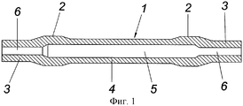
фиг.1 - продольный разрез колесной оси;figure 1 is a longitudinal section of a wheel axle;
фиг.2 - кузнечное устройство для осуществления способа в соответствии с изобретением для изготовления колесных осей в соответствии с фиг.1, в частности для железнодорожных вагонов, на схематичном виде сбоку, с частичным разрывом;figure 2 - forging device for implementing the method in accordance with the invention for the manufacture of wheel axles in accordance with figure 1, in particular for railway cars, in a schematic side view, with a partial gap;
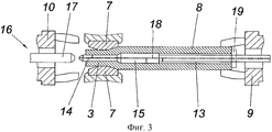
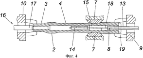
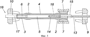
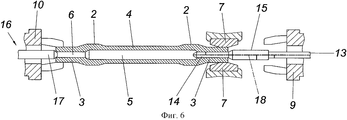
фиг.3-6 - фрагмент кузнечного устройства в зоне между двумя зажимными колодками с обеих сторон кузнечных инструментов, в схематичном продольном разрезе, в различных рабочих положениях.Fig.3-6 is a fragment of a forging device in the area between two clamping blocks on both sides of the forging tools, in a schematic longitudinal section, in various operating positions.
Как показано на фиг.1, кованая колесная ось имеет полый сквозной корпус 1 оси с двумя утолщенными гнездами 2 подшипников и с образующими уступы по отношению к гнездам 2 подшипников концами 3 оси для установки колес. Участок 4 корпуса оси между двумя гнездами 2 подшипников, который имеет уменьшенный по сравнению с гнездами 2 подшипников наружный диаметр, образует цилиндрическую полость 5 с увеличенным по сравнению с внутренним диаметром цилиндрических полостей 6 концов 3 оси внутренним диаметром.As shown in FIG. 1, the forged wheel axle has a hollow through
Представленное устройство для изготовления колесной оси для железнодорожного вагона с корпусом 1 оси в соответствии с фиг.1 содержит согласно фиг.2 в традиционном варианте попарно противолежащие друг другу кузнечные инструменты 7, к примеру, в виде кузнечных молотов, между которыми с целью обработки в аксиальном направлении, с одновременным вращением вокруг своей оси, подается трубообразная заготовка 8. Для этой цели с обеих сторон кузнечного инструмента 7 предусмотрены зажимные колодки 9, 10, которые с возможностью вращения установлены в соответствующем корпусе 11 и с помощью корпуса 11 могут перемещаться вдоль направляющей рамы 12. Из соображений лучшей наглядности работающий в прерывистом режиме приводной поворотный механизм для зажимных колодок 9, 10 не показан.The device for manufacturing a wheel axle for a railway carriage with an
В корпусе 11 для зажимной колодки 9 с возможностью аксиального перемещения располагается ступенчатый кузнечный сердечник 13, который формирует концевой профильный участок 14 с соответствующим внутреннему диаметру конца 3 оси наружным диаметром и примыкающий к нему профильный участок 15 для увеличенной цилиндрической полости 5 участка 4 корпуса оси. Для противолежащей зажимной колодки 10 предусмотрен также выполненный с возможностью аксиального перемещения сердечник 16, который предназначен для очистки от окалины внутренней поверхности полой заготовки 8 и имеет, к примеру, головку 17 щетки, которая дополнительно может быть оснащена не показанными форсунками для подачи на внутреннюю поверхность полой заготовки 8 воды под высоким давлением для содействия процессу удаления окалины с внутренней поверхности заготовки 8.In the housing 11 for the
Для формирования в процессе ковки корпуса 1 оси в соответствии с фиг.1 используется полая, трубообразная заготовка 8, которая в данном варианте выполнения изобретения имеет приведенный в соответствие с габаритами гнезд 2 подшипников корпуса 1 оси наружный диаметр с соответствующей толщиной стенки. Эта заготовка 8 после соответствующего нагрева до заданной температуры ковки зажимается в зажимной колодке 9 и перемещается в аксиальном направлении к противолежащей зажимной колодке 10 для очистки от окалины ее внутренней поверхность с помощью головки 17 щетки, которая посредством сердечника 16 вводится в полую заготовку 8, как показано стрелкой на фиг.2. По окончании поддержанного в предпочтительном варианте за счет подачи через форсунки воды высокого давления процесса очистки от окалины головка 17 щетки выводится из заготовки 8, а ступенчатый кованый сердечник 13 для формирования противолежащего зажимной колодке 9 конца 3 оси вводится в заготовку 8. На фиг.3 представлено данное положение кузнечного сердечника для формирования посредством ковки конца 3 оси. Таким образом, при прерывистом вращении заготовки 8 и соответствующем смещении посредством принимающего зажимную колодку 9 корпуса 11 вдоль направляющей рамы 12 может быть образован противолежащий зажимной колодке 9 конец 3 оси, посредством профильного участка 14 кузнечного сердечника 13, для формирования примыкающего гнезда 2 подшипника при неизменном относительном положении кузнечного сердечника 13 относительно заготовки 8.To form an axis during the forging of the
Формирование посредством ковки примыкающего к гнезду 2 подшипника участка 4 корпуса оси с увеличенной цилиндрической полостью 5 требует уменьшения наружного диаметра заготовки 8. Определяющий внутренний диаметр увеличенной полости 5 профильный участок 15 кузнечного сердечника 13 необходимо удерживать при этом напротив зоны ковки, что при аксиальном смещении заготовки 8 в процессе ковки через зажимную колодку 9 обеспечивает соответствующий смещению в процессе ковки возврат кузнечного сердечника 13, с целью обеспечения возможности опоры заготовки 8 в процессе ковки на профильный участок 15 кузнечного сердечника 13. В соответствии с фиг.4 после формирования посредством ковки участка 4 корпуса оси между обоими гнездами 2 подшипников корпуса 1 оси может быть сформировано ближнее к зажимной колодке 9 гнездо 2 подшипника, а именно посредством профильного участка 15 кузнечного сердечника 13, как показано на фиг.5. По меньшей мере для осуществления данного процесса зажимная колодка 10 должна взять на себя импульс смещения заготовки 8, чтобы беспрепятственно ввести кузнечные инструменты 7 через зажимную колодку 9.The formation by forging adjacent to the
Для осуществления заключительного этапа формирования посредством ковки конца 3 оси необходимо, однако, полностью вынуть профильный участок 15 кузнечного сердечника 13 из заготовки 8, чтобы оставшийся конец 3 оси мог быть обработан посредством ступенчатого профильного участка 14 кузнечного сердечника 13. На фиг.6 представлен данный этап обработки. В отличие от конца 3 оси на стороне, противолежащей зажимной колодке 9, образуется переход от увеличенной полости 5 участка 4 корпуса оси к полости 6 конца 3 оси, на стороне зажимной колодки 9 посредством, в основном, свободного прохождения инструмента. Это не влечет за собой, однако, никакого ущерба ни в отношении нагрузки на колесную ось, ни в отношении ультразвукового контроля.For the final stage of forming by forging the end of the 3 axis, however, it is necessary to completely remove the
Для предотвращения опасности повторного образования окалины в процессе ковки посредством кузнечного сердечника 13 в полую заготовку 8 может быть введено соответствующее защитное средство. Соответствующая траектория 18 проведения защитного средства посредством кузнечного сердечника 13 обозначена пунктирной линией. В качестве защитного средства может быть использован как защитный газ, так и защитная жидкость. Однако возможно также закрыть внутреннюю поверхность заготовки 8 защитным слоем, который предотвращает образование окалины. Чтобы введенное в полую заготовку 8 защитное средство не могло выйти из нее, эта полая заготовка 8 может быть закрыта с торцов. В соответствии с фиг.4-6 для этой цели используется головка 17 щетки сердечника 16. На противолежащей торцевой стороне заготовки могла бы быть предусмотрена обозначенная на фиг.3 и 4 пунктирной линией крышка 19, через которую проходит кузнечный сердечник 13.To prevent the danger of re-formation of scale during forging by means of the forging
Следует учесть, что изобретение не ограничено представленным вариантом выполнения. Так, могла бы быть использована трубообразная заготовка 8, наружный диаметр которой соответствует наружному диаметру участка 4 корпуса оси между гнездами 2 подшипников. Утолщенные гнезда 2 подшипников должны были бы быть предусмотрены в данном случае посредством того, что заготовка 8 в их зоне соответствующим образом высажена. Полая заготовка 8 могла бы быть, однако, изготовлена на кузнечном устройстве даже посредством того, что весь исходный материал сначала традиционным образом перфорируется с помощью пробойника.Note that the invention is not limited to the presented embodiment. So, a tube-shaped blank 8 could be used, the outer diameter of which corresponds to the outer diameter of the
Claims (4)
Applications Claiming Priority (3)
| Application Number | Priority Date | Filing Date | Title |
|---|---|---|---|
| ATA497/2010A AT509642B1 (en) | 2010-03-29 | 2010-03-29 | METHOD FOR THE PRODUCTION OF WHEEL AXES, ESPECIALLY FOR RAILWAY CARTS |
| ATA497/2010 | 2010-03-29 | ||
| PCT/AT2011/000145 WO2011120062A1 (en) | 2010-03-29 | 2011-03-24 | Method for producing wheel axles, in particular for railway carriages |
Publications (2)
| Publication Number | Publication Date |
|---|---|
| RU2012145872A RU2012145872A (en) | 2014-05-10 |
| RU2538136C2 true RU2538136C2 (en) | 2015-01-10 |
Family
ID=44276252
Family Applications (1)
| Application Number | Title | Priority Date | Filing Date |
|---|---|---|---|
| RU2012145872/02A RU2538136C2 (en) | 2010-03-29 | 2011-03-24 | Production of mounted axles, particularly, for passenger cars |
Country Status (7)
| Country | Link |
|---|---|
| EP (1) | EP2552614B1 (en) |
| CN (1) | CN102933329B (en) |
| AT (1) | AT509642B1 (en) |
| BR (1) | BR112012024426A2 (en) |
| RU (1) | RU2538136C2 (en) |
| UA (1) | UA107959C2 (en) |
| WO (1) | WO2011120062A1 (en) |
Families Citing this family (6)
| Publication number | Priority date | Publication date | Assignee | Title |
|---|---|---|---|---|
| CN104043769B (en) * | 2013-03-14 | 2016-03-02 | 雷帮荣 | Hot extrusion hole-bored axle from end to end straight forming technique |
| DE102013226929A1 (en) * | 2013-12-20 | 2015-06-25 | Volkswagen Aktiengesellschaft | Method and device for producing a hollow shaft by radial forming and hollow shaft produced therewith |
| DE102014214708B3 (en) * | 2014-07-25 | 2015-11-12 | Sms Meer Gmbh | Method for producing a multiple railway wheel set shaft and radial forging machine |
| DE102014218766A1 (en) * | 2014-09-18 | 2016-03-24 | Zf Friedrichshafen Ag | Shaft, gearbox and method for producing a shaft |
| DE102014218768A1 (en) * | 2014-09-18 | 2016-03-24 | Zf Friedrichshafen Ag | Shaft, gearbox and method for producing a shaft |
| CN107413884B (en) * | 2017-05-11 | 2019-12-27 | 泰州驰骏智能设备有限公司 | A device that contracts in for pipe part |
Citations (4)
| Publication number | Priority date | Publication date | Assignee | Title |
|---|---|---|---|---|
| SU416139A1 (en) * | 1972-02-11 | 1974-02-25 | ||
| SU902975A1 (en) * | 1980-06-18 | 1982-02-07 | Предприятие П/Я А-3681 | Method of producing stepped hollow forgings |
| UA16304U (en) * | 2005-09-20 | 2006-08-15 | Dnipropetrovsk Academician V L | Method of manufacture of hollow axle of the pair of wheels of rolling stock |
| RU2315673C2 (en) * | 2006-02-08 | 2008-01-27 | ОАО "Челябинский трубопрокатный завод" | Method for producing hot rolled commercial and conversion tubes of large and mean diameters of corrosion resistant hard-to-form kinds of steels and alloys in tube rolling plants with pilger mills |
Family Cites Families (8)
| Publication number | Priority date | Publication date | Assignee | Title |
|---|---|---|---|---|
| DE653067C (en) * | 1934-11-21 | 1937-11-13 | Ver Oberschlesische Huettenwer | Process for the production of hollow axles for railway vehicles |
| US2256065A (en) * | 1939-10-21 | 1941-09-16 | Pittsburgh Steel Co | Tubular car axle and method for making it |
| US4208900A (en) * | 1977-03-02 | 1980-06-24 | Lear Siegler, Inc. | Axle spindle forming apparatus |
| DE19523280C2 (en) * | 1995-06-27 | 2002-12-05 | Gfm Gmbh Steyr | Forging machine for internal profiling of tubular workpieces |
| AT501152B8 (en) * | 2003-12-30 | 2007-02-15 | Gfm Beteiligungs & Man Gmbh | METHOD AND DEVICE FOR PRODUCING A CYLINDRICAL HOLLOW BODY FROM A BOARD |
| DE102005052178B4 (en) * | 2004-10-25 | 2008-06-19 | V&M Deutschland Gmbh | Method for producing a seamless hot-worked steel tube |
| DE102004056147B3 (en) * | 2004-11-20 | 2006-08-03 | Gkn Driveline International Gmbh | Reduction of tubes over a stepped mandrel for producing hollow shafts with undercut in one operation |
| FR2926739B1 (en) * | 2008-01-24 | 2010-08-20 | Vallourec & Mannesmann Tubes | FORGED AXLE FROM WELDED TUBE FOR RAILWAY VEHICLES AND METHOD OF MANUFACTURING WRENCH AXLE FROM WELDED TUBE FOR RAILWAY VEHICLES |
-
2010
- 2010-03-29 AT ATA497/2010A patent/AT509642B1/en not_active IP Right Cessation
-
2011
- 2011-03-24 CN CN201180026816.6A patent/CN102933329B/en not_active Expired - Fee Related
- 2011-03-24 BR BR112012024426A patent/BR112012024426A2/en not_active Application Discontinuation
- 2011-03-24 RU RU2012145872/02A patent/RU2538136C2/en not_active IP Right Cessation
- 2011-03-24 EP EP11714912.0A patent/EP2552614B1/en not_active Revoked
- 2011-03-24 UA UAA201211473A patent/UA107959C2/en unknown
- 2011-03-24 WO PCT/AT2011/000145 patent/WO2011120062A1/en active Application Filing
Patent Citations (4)
| Publication number | Priority date | Publication date | Assignee | Title |
|---|---|---|---|---|
| SU416139A1 (en) * | 1972-02-11 | 1974-02-25 | ||
| SU902975A1 (en) * | 1980-06-18 | 1982-02-07 | Предприятие П/Я А-3681 | Method of producing stepped hollow forgings |
| UA16304U (en) * | 2005-09-20 | 2006-08-15 | Dnipropetrovsk Academician V L | Method of manufacture of hollow axle of the pair of wheels of rolling stock |
| RU2315673C2 (en) * | 2006-02-08 | 2008-01-27 | ОАО "Челябинский трубопрокатный завод" | Method for producing hot rolled commercial and conversion tubes of large and mean diameters of corrosion resistant hard-to-form kinds of steels and alloys in tube rolling plants with pilger mills |
Also Published As
| Publication number | Publication date |
|---|---|
| EP2552614B1 (en) | 2017-07-12 |
| EP2552614A1 (en) | 2013-02-06 |
| BR112012024426A2 (en) | 2016-05-31 |
| RU2012145872A (en) | 2014-05-10 |
| CN102933329B (en) | 2016-03-02 |
| WO2011120062A1 (en) | 2011-10-06 |
| UA107959C2 (en) | 2015-03-10 |
| AT509642B1 (en) | 2013-03-15 |
| AT509642A1 (en) | 2011-10-15 |
| CN102933329A (en) | 2013-02-13 |
Similar Documents
| Publication | Publication Date | Title |
|---|---|---|
| JP4633122B2 (en) | Method for producing seamless hot-finished steel pipe and apparatus for carrying out this method | |
| RU2538136C2 (en) | Production of mounted axles, particularly, for passenger cars | |
| CN101722262B (en) | New method for producing medium and large caliber alloy steel seamless pipe by utilizing radial forging technology | |
| RU2468884C2 (en) | Method of making rings | |
| EP1884296B1 (en) | Method of manufacturing ultrathin wall metallic tube by cold working method | |
| EP2976168B1 (en) | Method for producing a steel tube including cleaning of the inner tube wall | |
| CN100518989C (en) | Method for production of a seamless hot-finished steel tube and device for carrying out the method | |
| EP2976167B1 (en) | Method for producing a steel tube including cleaning of the outer tube wall | |
| CN102873126B (en) | Manufacturing method of large-aperture thin-walled seamless steel tube for nuclear power plant | |
| RU2597189C2 (en) | Rolling mill and method of rolling | |
| RU2354483C1 (en) | Vessel production method | |
| JP2006300019A (en) | Method of manufacturing hollow cam shaft | |
| RU2800273C1 (en) | Method for processing steel billet pipes to produce cold-rolled pipes | |
| JP2006170031A (en) | High-pressure fuel injection pipe having bending part and its bending method and device | |
| RU2615918C1 (en) | METHOD OF PRODUCING SEAMLESS MACHINED PIPES WITH 530x23-28 mm SIZE FROM THE STEEL GRADE "08Х18Н10-Ш" | |
| JP3920581B2 (en) | Manufacturing method for thick thin tube | |
| RU2615399C1 (en) | Method of producing seamless machined pipes with 530×18-22 mm size from steel of "08х18н10-ш" grade | |
| US20170165729A1 (en) | Compact plant for rolling seamless tubes | |
| RU2503523C2 (en) | Method of producing precision tubes and device to this end | |
| RU2615400C1 (en) | Method of producing seamless machined pipes with 530×13-17 mm size from steel of "08х18н10-ш" grade | |
| RU2615921C1 (en) | METHOD OF PRODUCING SEAMLESS MACHINED PIPES WITH 530x8-12 mm SIZE FROM THE STEEL GRADE 08X18H10T | |
| RU2054982C1 (en) | Vessel production method | |
| RU2133664C1 (en) | Method for making part with branched portions | |
| RU2570152C2 (en) | PRODUCTION OF 550×25-30 mm SEAMLESS HOT-ROLLED PIPES FOR STEAM BOILERS, STEAM PIPELINES AND MANIFOLDS OF PLANTS WITH HIGH AND SUPERHIGH STEAM PARAMETERS OF "10Х9МФБ-Ш"-GRADE STEEL | |
| JP2002066624A (en) | Manufacturing method for thick-walled small-diameter pipe |
Legal Events
| Date | Code | Title | Description |
|---|---|---|---|
| MM4A | The patent is invalid due to non-payment of fees |
Effective date: 20190325 |