RU2518219C2 - Positive temperature coefficient device - Google Patents
Positive temperature coefficient device Download PDFInfo
- Publication number
- RU2518219C2 RU2518219C2 RU2011122735/07A RU2011122735A RU2518219C2 RU 2518219 C2 RU2518219 C2 RU 2518219C2 RU 2011122735/07 A RU2011122735/07 A RU 2011122735/07A RU 2011122735 A RU2011122735 A RU 2011122735A RU 2518219 C2 RU2518219 C2 RU 2518219C2
- Authority
- RU
- Russia
- Prior art keywords
- ptc
- multilayer base
- temperature
- resin
- ptc element
- Prior art date
Links
Images


Classifications
-
- H—ELECTRICITY
- H01—ELECTRIC ELEMENTS
- H01C—RESISTORS
- H01C1/00—Details
- H01C1/14—Terminals or tapping points or electrodes specially adapted for resistors; Arrangements of terminals or tapping points or electrodes on resistors
- H01C1/1406—Terminals or electrodes formed on resistive elements having positive temperature coefficient
-
- H—ELECTRICITY
- H01—ELECTRIC ELEMENTS
- H01C—RESISTORS
- H01C7/00—Non-adjustable resistors formed as one or more layers or coatings; Non-adjustable resistors made from powdered conducting material or powdered semi-conducting material with or without insulating material
- H01C7/02—Non-adjustable resistors formed as one or more layers or coatings; Non-adjustable resistors made from powdered conducting material or powdered semi-conducting material with or without insulating material having positive temperature coefficient
-
- G—PHYSICS
- G01—MEASURING; TESTING
- G01K—MEASURING TEMPERATURE; MEASURING QUANTITY OF HEAT; THERMALLY-SENSITIVE ELEMENTS NOT OTHERWISE PROVIDED FOR
- G01K1/00—Details of thermometers not specially adapted for particular types of thermometer
- G01K1/16—Special arrangements for conducting heat from the object to the sensitive element
-
- G—PHYSICS
- G01—MEASURING; TESTING
- G01K—MEASURING TEMPERATURE; MEASURING QUANTITY OF HEAT; THERMALLY-SENSITIVE ELEMENTS NOT OTHERWISE PROVIDED FOR
- G01K7/00—Measuring temperature based on the use of electric or magnetic elements directly sensitive to heat ; Power supply therefor, e.g. using thermoelectric elements
- G01K7/16—Measuring temperature based on the use of electric or magnetic elements directly sensitive to heat ; Power supply therefor, e.g. using thermoelectric elements using resistive elements
- G01K7/22—Measuring temperature based on the use of electric or magnetic elements directly sensitive to heat ; Power supply therefor, e.g. using thermoelectric elements using resistive elements the element being a non-linear resistance, e.g. thermistor
-
- H—ELECTRICITY
- H01—ELECTRIC ELEMENTS
- H01C—RESISTORS
- H01C1/00—Details
- H01C1/01—Mounting; Supporting
-
- H—ELECTRICITY
- H01—ELECTRIC ELEMENTS
- H01C—RESISTORS
- H01C1/00—Details
- H01C1/02—Housing; Enclosing; Embedding; Filling the housing or enclosure
-
- H—ELECTRICITY
- H01—ELECTRIC ELEMENTS
- H01C—RESISTORS
- H01C1/00—Details
- H01C1/02—Housing; Enclosing; Embedding; Filling the housing or enclosure
- H01C1/032—Housing; Enclosing; Embedding; Filling the housing or enclosure plural layers surrounding the resistive element
-
- H—ELECTRICITY
- H01—ELECTRIC ELEMENTS
- H01C—RESISTORS
- H01C7/00—Non-adjustable resistors formed as one or more layers or coatings; Non-adjustable resistors made from powdered conducting material or powdered semi-conducting material with or without insulating material
- H01C7/02—Non-adjustable resistors formed as one or more layers or coatings; Non-adjustable resistors made from powdered conducting material or powdered semi-conducting material with or without insulating material having positive temperature coefficient
- H01C7/027—Non-adjustable resistors formed as one or more layers or coatings; Non-adjustable resistors made from powdered conducting material or powdered semi-conducting material with or without insulating material having positive temperature coefficient consisting of conducting or semi-conducting material dispersed in a non-conductive organic material
-
- H—ELECTRICITY
- H01—ELECTRIC ELEMENTS
- H01C—RESISTORS
- H01C7/00—Non-adjustable resistors formed as one or more layers or coatings; Non-adjustable resistors made from powdered conducting material or powdered semi-conducting material with or without insulating material
- H01C7/02—Non-adjustable resistors formed as one or more layers or coatings; Non-adjustable resistors made from powdered conducting material or powdered semi-conducting material with or without insulating material having positive temperature coefficient
- H01C7/028—Non-adjustable resistors formed as one or more layers or coatings; Non-adjustable resistors made from powdered conducting material or powdered semi-conducting material with or without insulating material having positive temperature coefficient consisting of organic substances
-
- Y—GENERAL TAGGING OF NEW TECHNOLOGICAL DEVELOPMENTS; GENERAL TAGGING OF CROSS-SECTIONAL TECHNOLOGIES SPANNING OVER SEVERAL SECTIONS OF THE IPC; TECHNICAL SUBJECTS COVERED BY FORMER USPC CROSS-REFERENCE ART COLLECTIONS [XRACs] AND DIGESTS
- Y10—TECHNICAL SUBJECTS COVERED BY FORMER USPC
- Y10T—TECHNICAL SUBJECTS COVERED BY FORMER US CLASSIFICATION
- Y10T29/00—Metal working
- Y10T29/49—Method of mechanical manufacture
- Y10T29/49002—Electrical device making
- Y10T29/49117—Conductor or circuit manufacturing
- Y10T29/49124—On flat or curved insulated base, e.g., printed circuit, etc.
- Y10T29/4913—Assembling to base an electrical component, e.g., capacitor, etc.
Abstract
Description
ОБЛАСТЬ ТЕХНИЧЕСКОГО ПРИМЕНЕНИЯFIELD OF TECHNICAL APPLICATION
[0001] Данное изобретение относится к устройствам ПТК, имеющим элемент ПТК, в частности полимерный элемент ПТК (с положительным температурным коэффициентом) и электрический прибор, содержащий данное устройство ПТК.[0001] The present invention relates to PTC devices having a PTC element, in particular a PTC polymer element (with a positive temperature coefficient) and an electrical device comprising this PTC device.
УРОВЕНЬ ТЕХНИКИBACKGROUND
[0002] Полимерный элемент ПТК имеет свойство быстрого увеличения коэффициента сопротивления, чтобы, например, предотвратить перегрев электрического прибора или повреждение, возникающего от избыточного тока, например, если температура элемента ПТК превышает заданную критическую величину, то есть он имеет свойство положительного температурного коэффициента или свойство ПТК. Такая критическая температура далее называется «температура отключения».[0002] The PTC polymer element has the property of rapidly increasing the resistance coefficient, for example, to prevent overheating of the electrical device or damage resulting from excess current, for example, if the temperature of the PTC element exceeds a predetermined critical value, that is, it has a positive temperature coefficient property or property PTK. This critical temperature is hereinafter referred to as the “trip temperature”.
[0003] Подложка (плата), на которую монтируется интегральная микросхема и которая встроена в электроприбор, обычно имеет радиаторную пластину для рассеивания тепла, образующегося при использовании электроприбора, на наружную сторону. В случае если такая подложка нагревается до чрезмерно высокой температуры по каким-либо причинам, например, из-за протекания избыточного тока через подложку, рассеивание тепла через радиаторную пластину может быть недостаточным, и поэтому радиаторная пластина и подложка разогреваются и сохраняют чрезмерно высокую температуру. Вследствие этого, к радиаторной пластине крепится керамический элемент ПТК (например, POSISTOR (зарегистрированная торговая марка), произведенный «Murata Manifacturing Co., Ltd.», Япония), таким образом, выявляется температура подложки и косвенно предотвращается разогрев подложки до чрезвычайно высокой температуры.[0003] The substrate (board) on which the integrated circuit is mounted and which is built into the appliance usually has a radiator plate to dissipate the heat generated when using the appliance to the outside. If such a substrate is heated to an excessively high temperature for some reason, for example, due to the flow of excess current through the substrate, heat dissipation through the radiator plate may be insufficient, and therefore the radiator plate and substrate are heated and maintain an excessively high temperature. As a result, a PTC ceramic element (for example, POSISTOR (registered trademark) manufactured by Murata Manifacturing Co., Ltd., Japan) is attached to the radiator plate, thereby detecting the temperature of the substrate and indirectly preventing the substrate from heating to an extremely high temperature.
[Ссылка на патент 1][Patent reference 1]
Японский патент, опубликованный для ознакомления, №04-162701Japanese Patent Published For Acquisition No. 04-162701
ОПИСАНИЕ ИЗОБРЕТЕНИЯDESCRIPTION OF THE INVENTION
Проблема, рассматриваемая в изобретении.The problem considered in the invention.
[0004] Хотя данный керамический элемент ПТК имеет функцию предотвращения разогрева подложки до чрезвычайно высокой температуры, такая функция не является достаточной в некоторых случаях. Например, увеличение коэффициента сопротивления в течение времени при увеличении температуры не так высоко, то есть коэффициент сопротивления не возрастает резко за короткий интервал, так что такой элемент ПТК иногда не способен отключить ток за необходимо короткое время. Поэтому везде используется способ, при котором ток отключается не элементом ПТК, а непрямым способом, когда сопротивление керамического элемента ПТК достигает заданной величины. В частности, желательно быстрее выявить возможность разогрева подложки до чрезвычайно высокой температуры, чтобы напрямую и заранее предотвратить разогрев подложки до такой чрезвычайно высокой температуры.[0004] Although this ceramic PTC element has the function of preventing the substrate from heating to an extremely high temperature, such a function is not sufficient in some cases. For example, the increase in the resistance coefficient over time with increasing temperature is not so high, that is, the resistance coefficient does not increase sharply in a short interval, so such a PTC element is sometimes not able to turn off the current in a necessary short time. Therefore, everywhere a method is used in which the current is switched off not by the PTC element, but by an indirect method, when the resistance of the PTC ceramic element reaches a predetermined value. In particular, it is desirable to quickly identify the possibility of heating the substrate to an extremely high temperature in order to directly and in advance prevent the heating of the substrate to such an extremely high temperature.
Способы решения проблемыWays to solve the problem
[0005] Проводились обширные исследования по данной проблеме, и было обнаружено, что данную проблему можно решить с помощью устройства ПТК, в котором используется полимерный элемент ПТК, который далее подвергается вплавлению при условии, когда ПТК элемент установлен в основание.[0005] Extensive research has been conducted on this problem, and it has been found that this problem can be solved with a PTC device that uses a PTC polymer element, which is then fused under the condition that the PTC element is installed in the base.
[0006] Соответственно, в первом аспекте данное изобретение представляет устройство ПТК, включающее в себя многослойное основание, которое выступает в качестве теплопроводной среды, и полимерный элемент ПТК, расположенный на основании, так что полимерный элемент ПТК расположен на поверхности многослойного основания (в термически подключенном состоянии), и элемент ПТК и многослойное основание впаяны в связующее (смолу) так, что снаружи остается другая стороны многослойного основания.[0006] Accordingly, in a first aspect, the present invention provides a PTC device including a multilayer base that acts as a heat-conducting medium, and a PTC polymer element located on the base, so that the PTC polymer element is located on the surface of the multilayer base (thermally connected state), and the PTC element and the multilayer base are soldered into the binder (resin) so that the other side of the multilayer base remains outside.
[0007] В данном изобретении в устройстве ПТК элемент ПТК впаян в смолу. В результате впаянный элемент ПТК изолирован от окружающей устройство ПТК среды смолой. Например, эта смола может предотвратить попадание влаги на элемент ПТК, его окисление и/или другое воздействие среды вокруг устройства. Так, особенно важно, чтобы смола выполняла функции защиты от влаги, кислорода и тому подобного.[0007] In the present invention, in the PTC device, the PTC element is soldered to the resin. As a result, the soldered PTC element is isolated from the surrounding PTC device by the resin. For example, this resin can prevent moisture from entering the PTC element, its oxidation and / or other environmental effects around the device. So, it is especially important that the resin serves as a protection against moisture, oxygen, and the like.
[0008] Многослойное основание может термически контактировать с объектом, температура которого должна выявляться устройством ПТК. Термин «термический контакт (термически контактировать)» означает, что наружная сторона многослойного основания контактирует с поверхностью объекта, поэтому тепло быстро проводится от объекта на наружную сторону многослойного основания. В результате такого термического контакта внешняя сторона многослойного основания предпочтительно достигает температуры, практически равной температуре поверхности объекта. В результате такого термического контакта внешняя сторона многослойного основания более вероятно приобретает температуру, практически равную температуре противоположной стороны (не внешней) многослойного основания.[0008] A multilayer base may be thermally in contact with an object whose temperature is to be detected by a PTC device. The term "thermal contact (thermally contact)" means that the outer side of the multilayer base is in contact with the surface of the object, therefore, heat is quickly transferred from the object to the outer side of the multilayer base. As a result of such thermal contact, the outer side of the multilayer base preferably reaches a temperature substantially equal to the surface temperature of the object. As a result of such thermal contact, the outer side of the multilayer base is more likely to acquire a temperature almost equal to the temperature of the opposite side (not external) of the multilayer base.
[0009] Предпочтительно использовать теплопроводный материал, в частности, материал, имеющий превосходную теплопроводность, например, металл, такой как нержавеющая сталь, медь и подобные им материалы для изготовления многослойного основания. Также возможно использование материала, имеющего худшую теплопроводность, например, композитный материал, такой как эпоксистеклопластик (композиционный материал на эпоксидной матрице, армированный стекловолокном) или другие керамические материалы, если материал достаточно тонкий, что приводит к не такому большому сопротивлению теплопроводности.[0009] It is preferable to use a thermally conductive material, in particular a material having excellent thermal conductivity, for example, metal, such as stainless steel, copper and the like, for the manufacture of a multilayer base. It is also possible to use a material having worse thermal conductivity, for example, a composite material, such as epoxy-plastic (composite material on an epoxy matrix reinforced with fiberglass) or other ceramic materials, if the material is thin enough, which leads to not so much thermal conductivity.
[0010] Полимерный элемент ПТК термически соединен с многослойным основанием. В результате получается конструкция, в которой тепло отводится, предпочтительно быстро, от внешней стороны многослойного основания и, следовательно, от объекта, на котором установлен элемент ПТК. Так, выражение «многослойное основание выступает в качестве теплопроводной среды» используется в данном описании в том смысле, что тепло отводится от объекта на элемент ПТК. Отмечено, что полимерный элемент ПТК может быть прямо или непрямо соединен с многослойным основанием.[0010] The PTC polymer element is thermally coupled to the multilayer base. The result is a structure in which heat is removed, preferably quickly, from the outside of the multilayer base and, therefore, from the object on which the PTC element is mounted. So, the expression "multilayer base acts as a heat-conducting medium" is used in this description in the sense that heat is removed from the object to the PTC element. It is noted that the PTC polymer element can be directly or indirectly connected to the multilayer base.
[0011] Напрямую соединенный с многослойным основанием полимерный элемент ПТК относится к варианту осуществления, в котором никакой материал не находится между элементом и основанием, а не напрямую соединенный, соответственно, относится к варианту осуществления в котором между элементом и основанием есть материал. Такой материал может быть клеящим веществом (например, клей, припой, электропроводящий клей, электропроводящая паста и тому подобное) и электроизолирующим веществом и тому подобным, и такой материал обычно является слоем.[0011] The PTC polymer element directly connected to the multilayer base refers to an embodiment in which no material is between the element and the base, and not directly connected, respectively, relates to an embodiment in which there is material between the element and the base. Such a material may be an adhesive (e.g., glue, solder, conductive adhesive, conductive paste and the like) and an electrically insulating substance and the like, and such a material is usually a layer.
[0012] Как уже видно из вышесказанного, многослойное основание соединено с элементом ПТК посредством теплопроводного материала, в частности, материала, имеющего превосходную теплопроводность, например, металла в случае непрямого соединения. Также возможно использование материала с меньшей теплопроводностью, например, керамического материала, если он имеет относительно небольшую толщину, что приводит к не такому большому сопротивлению при передаче тепла.[0012] As already seen from the above, the multilayer base is connected to the PTC element by means of a heat-conducting material, in particular, a material having excellent thermal conductivity, for example, metal in the case of indirect connection. It is also possible to use a material with lower thermal conductivity, for example, a ceramic material, if it has a relatively small thickness, which leads to not so much resistance to heat transfer.
[0013] Во втором аспекте данное изобретение представляет собой способ изготовления устройства ПТК, состоящего из многослойного основания и прикрепленного к нему полимерного элемента ПТК; способ включает в себя:[0013] In a second aspect, the invention is a method for manufacturing a PTC device, comprising a multilayer base and a PTC polymer element attached thereto; The method includes:
расположение полимерного элемента ПТК на поверхности многослойного основания; иthe location of the PTC polymer element on the surface of the multilayer base; and
сплавление многослойного основания с полимерным элементом ПТК таким образом, что снаружи остается другая сторона многослойного основания.fusion of the multilayer base with the PTC polymer element in such a way that the other side of the multilayer base remains outside.
В соответствии с таким способом изготавливается вышеупомянутое устройство ПТК. Отмечено, что полимерный элемент ПТК может быть прямо или непрямо расположен на многослойном основании, аналогично соединению вышеупомянутого полимерного элемента ПТК с многослойным основанием.In accordance with this method, the aforementioned PTC device is manufactured. It is noted that the PTC polymer element can be directly or indirectly located on the multilayer base, similar to the connection of the above PTC polymer element with a multilayer base.
[0014] Третий аспект настоящего изобретения представляет электрический прибор, который включает в себя вышеупомянутое устройство ПТК. Например, такой электрический прибор включает в себя схемную плату, в частности, подложку интегральной микросхемы для схемы регулирования мощности, электронный модуль, детектор перегрева и тому подобное, что составляет данное устройство ПТК.[0014] A third aspect of the present invention is an electrical device that includes the aforementioned PTC device. For example, such an electrical device includes a circuit board, in particular, an integrated circuit substrate for a power control circuit, an electronic module, an overheat detector, and the like that make up this PTC device.
НАЗНАЧЕНИЕ ИЗОБРЕТЕНИЯSUMMARY OF THE INVENTION
[0015] Данное устройство ПТК изготавливается путем комбинации полимерного элемента ПТК, имеющего большую чувствительность, чем керамический элемент ПТК, и многослойного основания, которые спаиваются таким образом, что одна поверхность основания остается снаружи. В результате повышение температуры объекта быстро передается на полимерный элемент ПТК, и затем полимерный элемент ПТК может активизироваться в зависимости от повышения температуры, когда устройство ПТК помещается на объект таким образом, что наружная сторона многослойного основания контактирует с объектом, аномальная температура которого должна быть выявлена. То есть высокую чувствительность полимерного элемента ПТК можно эффективно использовать, так как повышение температуры может быстро отводиться от объекта на полимерный элемент ПТК.[0015] This PTC device is manufactured by combining a PTC polymer element having greater sensitivity than the PTC ceramic element and a multilayer base that are soldered so that one surface of the base remains outside. As a result, the temperature increase of the object is quickly transmitted to the PTC polymer element, and then the PTC polymer element can be activated depending on the temperature increase when the PTC device is placed on the object so that the outer side of the multilayer base contacts the object whose abnormal temperature should be detected. That is, the high sensitivity of the PTC polymer element can be effectively used, since an increase in temperature can quickly be diverted from the object to the PTC polymer element.
КРАТКОЕ ОПИСАНИЕ СХЕМBRIEF DESCRIPTION OF SCHEMES
[0016][0016]
Фиг.1 демонстрирует схематическое поперечное сечение устройства ПТК данного изобретения.Figure 1 shows a schematic cross section of a PTC device of the present invention.
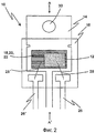
Фиг.2 демонстрирует схематический план устройства ПТК, показанного на фиг.1, с левой стороны фиг.1 устройства.Figure 2 shows a schematic plan of the PTC device shown in figure 1, on the left side of figure 1 of the device.
Фиг.3 демонстрирует результат измерения характеристики сопротивления-температуры данного устройства ПТК в примере 1.Figure 3 shows the result of measuring the resistance-temperature characteristics of this PTC device in Example 1.
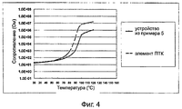
Фиг.4 демонстрирует результат измерения характеристики сопротивления-температуры данного устройства ПТК в примере 5.Figure 4 shows the result of measuring the resistance-temperature characteristics of this PTC device in Example 5.
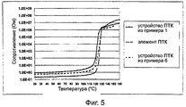
Фиг.5 демонстрирует результат измерения характеристики сопротивления-температуры данного устройства ПТК в примере 6.Figure 5 shows the result of measuring the resistance-temperature characteristics of this PTC device in Example 6.
Фиг.6 демонстрирует переход температуры термопары и коэффициент сопротивления в течение времени данного устройства ПТК в примере 1, когда увеличивается окружающая температура.6 shows the transition of the thermocouple temperature and the resistance coefficient over time of this PTC device in Example 1, when the ambient temperature increases.
Фиг.7 демонстрирует переход температуры термопары и коэффициент сопротивления в течение времени неорганического элемента ПТК, когда увеличивается окружающая температура.Fig. 7 shows the temperature transition of the thermocouple and the resistance coefficient over time of the inorganic PTC element when the ambient temperature increases.
ПОЯСНЕНИЕ К ССЫЛКАМLINK EXPLANATION
[0017] 10: устройство ПТК; 12: элемент ПТК; 14: многослойное основание; 15, 15': основные поверхности; 16: формовочная смола; 18: слой припойного материала; 20: слой изоляционного материала; 22: слой серебряной пасты; 24: элемент заливки; 26, 26': контакты; 28, 28': провод; 30: отверстие; 32: объект.[0017] 10: PTC device; 12: PTC element; 14: multilayer base; 15, 15 ': main surfaces; 16: molding resin; 18: a layer of solder material; 20: layer of insulating material; 22: a layer of silver paste; 24: fill element; 26, 26 ': contacts; 28, 28 ': wire; 30: hole; 32: object.
ВАРИАНТЫ ОСУЩЕСТВЛЕНИЯ ИЗОБРЕТЕНИЯMODES FOR CARRYING OUT THE INVENTION
[0018] Полимерный элемент ПТК, который составляет основу устройства ПТК данного изобретения, хорошо известен, и различные типы элементов имеются в продаже. Такой полимерный элемент ПТК используется здесь как предмет в повседневном значении. Полимерный элемент ПТК состоит из полимерного компонента ПТК, имеющего слоистую структуру, которая образуется из так называемого полимерного состава ПТК, и преимущественно содержит каждый из первых металлических электродов (в частности, электрод из металлизированной фольги) и второго металлического электрода (в частности, электрод из металлизированной фольги), помещенных на каждой из поверхностей элемента ПТК соответственно. Полимерный компонент ПТК выполнен из так называемого электропроводного полимерного состава, в котором электропроводный наполнитель, например, угольный наполнитель, металлический наполнитель (включая наполнитель из меди, никеля и кобальт-никелевого сплава или аналогичных материалов), распылен на полимерном материале (например, полиэтилене, поливинилидене, поливинилиден флюориде и т.п.). Компонент ПТК можно изготовить путем формовки выдавливанием из такого состава.[0018] The PTC polymer element, which forms the basis of the PTC device of the present invention, is well known, and various types of elements are commercially available. Such a PTC polymer element is used here as an item in everyday life. The PTC polymer element consists of the PTC polymer component having a layered structure, which is formed from the so-called PTC polymer composition, and mainly contains each of the first metal electrodes (in particular, a metallized foil electrode) and a second metal electrode (in particular, a metallized electrode foil) placed on each of the surfaces of the PTC element, respectively. The polymer component of PTC is made of a so-called electrically conductive polymer composition in which an electrically conductive filler, for example, a carbon filler, a metal filler (including filler of copper, nickel and cobalt-nickel alloy or similar materials) is sprayed onto a polymeric material (for example, polyethylene, polyvinylidene) , polyvinylidene fluoride, etc.). The PTC component can be made by extrusion molding from such a composition.
[0019] В качестве многослойного основания можно использовать любой материал; он должен иметь две противоположные поверхности, и его можно размещать, прямо или непрямо, на одной из основных поверхностей элемента ПТК в качестве теплопроводного материала для полимерного элемента ПТК. Точнее, металлический слой, например, металлическая пластина или металлическое покрытие, может использоваться как многослойное основание. В одном варианте выполнения материал такой же, как материал металлической выводной рамки (например, нержавеющая сталь или другой соответствующий металл), который используется в подложке с печатными соединениями. В другом варианте выполнения многослойное основание может быть сделано из керамического материала. Предпочтительно, чтобы многослойное основание имело большую площадь поверхности, чем площадь элемента ПТК, который располагается на ней. То есть предпочтительно, чтобы часть многослойного основания выходила хотя бы за часть периферии элемента ПТК, и предпочтительно, чтобы за всю периферию элемента ПТК при размещении элемента ПТК на многослойном основании так, чтобы элемент ПТК был виден сверху.[0019] As a multilayer base, any material may be used; it should have two opposite surfaces, and it can be placed, directly or indirectly, on one of the main surfaces of the PTC element as a heat-conducting material for the PTC polymer element. More specifically, a metal layer, for example, a metal plate or a metal coating, can be used as a multilayer base. In one embodiment, the material is the same as the material of the metal lead frame (for example, stainless steel or other appropriate metal) that is used in the substrate with printed compounds. In another embodiment, the multilayer base may be made of ceramic material. Preferably, the multilayer base has a larger surface area than the area of the PTC element that is located on it. That is, it is preferable that a part of the multilayer base extends at least part of the periphery of the PTC element, and it is preferable that the entire periphery of the PTC element when the PTC element is placed on the multilayer base so that the PTC element is visible from above.
[0020] В случае если многослойное основание изготовлено из электропроводного материала, при размещении полимерного элемента ПТК на многослойном основании необходимо поместить электроизолирующий материал между элементом ПТК и многослойным основанием. В случае если многослойное основание изготовлено из электроизолирующего материала, нет необходимости помещать таковой электроизолирующий материал между ними. Предпочтительно, чтобы электроизолирующий материал имел слоистую структуру.[0020] If the multilayer base is made of an electrically conductive material, when placing the PTC polymer element on the multilayer base, it is necessary to place an electrically insulating material between the PTC element and the multilayer base. If the multilayer base is made of an electrically insulating material, there is no need to place such an electrically insulating material between them. Preferably, the electrically insulating material has a layered structure.
[0021] В случае если электроизолирующий материал расположен между основанием и элементом, слой электроизолирующего материала прикрепляется к многослойному основанию посредством клеящего материала, и элемент ПТК также крепится к этому слою электроизолирующего материала посредством клеящего материала. Эти клеящие материалы, которые могут быть идентичными или разными, предпочтительно должны иметь теплопроводность, и более предпочтительно должны иметь превосходную теплопроводность. Например, припой, электропроводный клей, электропроводная паста (например, серебряная паста), припойная паста, электропроводный клей и тому подобное могут использоваться для такого крепления.[0021] If the electrically insulating material is located between the base and the element, the layer of electrically insulating material is attached to the multilayer base by means of adhesive material, and the PTC element is also attached to this layer of electrically insulating material by means of adhesive material. These adhesive materials, which may be identical or different, should preferably have thermal conductivity, and more preferably should have excellent thermal conductivity. For example, solder, conductive adhesive, conductive paste (eg, silver paste), solder paste, conductive adhesive and the like can be used for such fastening.
[0022] В данном устройстве ПТК элемент ПТК и многослойное основание подвергаются формовке пайкой, так что противоположная сторона многослойного основания (т.е. сторона, на которой не расположен элемент ПТК) остается снаружи. При формовке многослойное основание, на которое помещается элемент ПТК, устанавливается в заранее определенную форму таким образом, что другая сторона многослойного основания остается снаружи; после этого в форму заливается смола, после чего смола затвердевает и/или вулканизируется.[0022] In this PTC device, the PTC element and the multilayer base are brazed so that the opposite side of the multilayer base (ie, the side on which the PTC element is not located) remains outside. During molding, the multilayer base on which the PTC element is placed is installed in a predetermined shape so that the other side of the multilayer base remains outside; the resin is then poured into the mold, after which the resin hardens and / or cures.
[0023] Смола, заливаемая в форму, то есть формовочная смола, является отверждаемой смолой, например, можно использовать термоотверждаемую смолу или светоотверждаемую смолу, радиационноотверждаемую смолу, или, например, различные эпоксидные смолы или силиконовые смолы и тому подобное. В другом варианте осуществления заливаемая смола может быть термопластичной смолой. В этом случае смола в расплавленном состоянии заливается в форму, а затем она застывает в процессе охлаждения. Вышеупомянутый процесс формования сам по себе хорошо известен и выполняется таким образом, чтобы по крайне мере часть, предпочтительно большая часть, и еще более предпочтительно практически вся обратная сторона многослойного основания была снаружи. Формовочная смола служит для того, чтобы элемент ПТК, будучи вплавленным в нее, изолировался бы от среды устройства ПТК. В частности, она предохраняет элемент ПТК от неблагоприятного воздействия влаги, кислорода и тому подобного, что окружает устройство ПТК.[0023] The moldable resin, that is, the molding resin, is a curable resin, for example, a thermosetting resin or a light-curing resin, a radiation-curing resin, or, for example, various epoxies or silicone resins and the like, can be used. In another embodiment, the resin to be filled may be a thermoplastic resin. In this case, the resin in the molten state is poured into the mold, and then it solidifies during the cooling process. The aforementioned molding process is well known per se and is performed in such a way that at least a portion, preferably a large portion, and even more preferably substantially the entire reverse side of the multilayer base is outside. The molding resin serves to ensure that the PTC element, being fused into it, is isolated from the medium of the PTC device. In particular, it protects the PTC element from the adverse effects of moisture, oxygen and the like that surrounds the PTC device.
[0024] В особенно предпочтительном варианте осуществления данного изобретения элемент ПТК, помещенный на многослойное основание, предварительно герметизируется предварительной заливкой отверждаемой смолой, после чего смола отвердевает, таким образом получается заливочный элемент, который затем подвергается формовке. В этом контексте термин «заливка» означает процесс покрытия элемента смолой с помощью так называемого «набрасывания смолы», после чего покрывающая смола затвердевает. Обычно отверждаемая смола набрасывается на элемент ПТК, помещенный на многослойное основание, после чего оно затвердевает. Набрасывание смолы выполняется таким образом, что весь элемент ПТК, помещенный на многослойное основание, покрывается смолой. В результате элемент ПТК покрыт твердой смолой на многослойном основании, то есть покрытие на элементе ПТК образует заливочный элемент. Безусловно требуется, чтобы по крайней мере часть противоположной стороны многослойного основания оставалась снаружи во время процедуры заливки. Поэтому процедура заливки может подразумевать способ, при котором снаружи остается часть многослойного основания, остальная же часть герметизируется. Следует отметить, что, чтобы ток проходил через элемент ПТК, провод(а) или проводка, подсоединенные к элементу ПТК, должны выходить наружу заливочного элемента. Таким образом, элемент ПТК, расположенный на многослойном основании, покрыт заливочным элементом, после чего осуществляется формовка.[0024] In a particularly preferred embodiment of the present invention, the PTC element, placed on the multilayer base, is pre-sealed by pre-pouring with a curable resin, after which the resin solidifies, thereby forming a casting element, which is then molded. In this context, the term “pouring” means the process of coating an element with a resin using a so-called “resin casting”, after which the coating resin solidifies. Typically, a curable resin is poured onto a PTC element placed on a multilayer base, after which it hardens. The resin is sprayed in such a way that the entire PTC element placed on the multilayer base is coated with resin. As a result, the PTC element is coated with a solid resin on a multilayer base, that is, the coating on the PTC element forms a casting element. It is certainly required that at least part of the opposite side of the multilayer base remain outside during the pouring procedure. Therefore, the pouring procedure may involve a method in which part of the multilayer base remains outside, while the rest is sealed. It should be noted that in order for the current to pass through the PTC element, the wire (a) or wiring connected to the PTC element must go outside the filling element. Thus, the PTC element located on a multilayer base is covered with a casting element, after which molding is carried out.
[0025] В случае если элемент ПТК, покрытый заливочным элементом, подвергается формовке, расплавленная или размягченная горячая смола вводится в форму, в которую помещается ПТК элемент. В этом случае горячая смола не контактирует напрямую с элементом ПТК, так что воздействие температуры от горячей смолы на элемент ПТК гасится.[0025] If the PTC element coated with the casting element is molded, the molten or softened hot resin is introduced into the mold into which the PTC element is placed. In this case, the hot resin does not directly contact the PTC element, so that the effect of temperature from the hot resin on the PTC element is suppressed.
[0026] В частности, в случае, когда в качестве смолы для элемента ПТК используется полиэтилен, точка плавления которого варьируется, например, от 180°С до 240°С, а горячая эпоксидная смола в жидком состоянии при температуре около 180°С вводится в форму в качестве смолы для формования элемента, заливочный элемент располагается между элементом ПТК и формовочной смолой. В результате заливочный элемент выступает в качестве изолирующего материала от температурного воздействия горячей жидкости на элемент ПТК.[0026] In particular, in the case where polyethylene is used as the resin for the PTC element, the melting point of which varies, for example, from 180 ° C to 240 ° C, and hot epoxy resin is introduced into the liquid state at a temperature of about 180 ° C as a resin for molding the element, the casting element is located between the PTC element and the molding resin. As a result, the pouring element acts as an insulating material from the temperature effect of hot liquid on the PTC element.
[0027] Помимо, или вместо, буферных функций относительно вышеупомянутого температурного воздействия, когда формовочная смола, в частности, смола, заливаемая в форму, может оказать отрицательное химическое воздействие на элемент ПТК, заливочный элемент может служить буферным материалом для предотвращения негативного воздействия на элемент ПТК. Например, такой полимер как полиэтилен, который составляет компонент ПТК, может разрушаться или разлагаться под воздействием органического растворителя или масла. Заливочный элемент предохраняет элемент ПТК, насколько возможно, от прямого контакта с химическим компонентом (например, отверждающим веществом), содержащимся в расплавленной и/или размягченной смоле, которая вливается в форму во время процесса формовки.[0027] In addition to, or instead of, the buffer functions with respect to the aforementioned temperature effects, when the molding resin, in particular the resin cast into the mold, can have a negative chemical effect on the PTC element, the casting element can serve as a buffer material to prevent negative effects on the PTC element . For example, a polymer such as polyethylene, which makes up the PTC component, can break down or decompose under the influence of an organic solvent or oil. The casting element protects the PTC element as much as possible from direct contact with a chemical component (for example, a curing agent) contained in the molten and / or softened resin that is poured into the mold during the molding process.
[0028] В связи с вышесказанным отверждаемая смола, образующая заливочный элемент, может быть любой из подходящих отверждаемых смол. Например, предпочтительны термореактивные смолы (например, эпоксидная смола, силиконовая смола и тому подобное). В другом варианте осуществления отверждаемая смола, образующая заливочный элемент, может быть светоотверждаемой смолой или радиационноотверждаемой смолой. В случае если смола, используемая для формовки, является отверждаемой смолой, такая отверждаемая смола должна отличаться от отверждаемой смолы, которая образует заливочный элемент. В качестве отверждаемой смолы, которая образует заливочный элемент, предпочтительно использовать смолу, имеющую больший коэффициент линейного расширения после отвердения, чем такой же коэффициент формовочной смолы при температуре отключения элемента ПТК. Кроме того, предпочтительно, чтобы отверждаемая смола для заливочного элемента после отвердевания имела коэффициент линейного расширения, равный или меньший, чем такой же коэффициент полимере в компоненте ПТК, который образует элемент ПТК.[0028] In connection with the foregoing, the curable resin forming the casting member may be any of a suitable curable resin. For example, thermosetting resins are preferred (e.g., epoxy resin, silicone resin, and the like). In another embodiment, the curable resin constituting the casting member may be a light curable resin or a radiation curable resin. If the resin used for molding is a curable resin, such a curable resin must be different from the curable resin that forms the casting member. As the curable resin that forms the casting element, it is preferable to use a resin having a higher coefficient of linear expansion after curing than the same coefficient of the molding resin at the shutdown temperature of the PTC element. In addition, it is preferable that the curable resin for the casting element after curing has a linear expansion coefficient equal to or less than the same coefficient of the polymer in the PTC component that forms the PTC element.
[0029] В целом, предпочтительно, чтобы смола, которая образует заливочный элемент, имела коэффициент линейного расширения не менее 3,0×10⁻⁵/°С и не более 40,0×10⁻⁵/°С, особенно не более 30,0×10⁻⁵/°С при температуре выше, чем Тс (температура стеклования) после отвердевания. Коэффициент линейного расширения смолы после отвердевания может варьироваться, например, от 10×10-5/°С до 20×10-5/°С. В случае, если полимер, образующий полимерный элемент ПТК, является полиэтиленом, особенно предпочтительно, чтобы смола после отвердевания имела коэффициент линейного расширения в пределах вышеупомянутых параметров. Например, в случае, когда смола, образующая заливочный элемент, является эпоксидной смолой, предпочтительно иметь коэффициент линейного расширения не меньший 3,0×10⁻⁵/°C и не больший 40,0×10⁻⁵/°С после отвердевания при температуре, приблизительно равной температуре отключения элемента ПТК.[0029] In General, it is preferable that the resin that forms the casting element, had a linear expansion coefficient of not less than 3.0 × 10 -5 / ° C and not more than 40.0 × 10 -5 / ° C, especially not more than 30 , 0 × 10 -5 / ° C at a temperature higher than Tc (glass transition temperature) after hardening. The coefficient of linear expansion of the resin after hardening can vary, for example, from 10 × 10 −5 / ° C to 20 × 10 −5 / ° C. In the case where the polymer forming the PTC polymer element is polyethylene, it is particularly preferred that the resin after curing has a linear expansion coefficient within the above parameters. For example, in the case where the resin constituting the casting member is an epoxy resin, it is preferable to have a linear expansion coefficient of not less than 3.0 × 10 -5 / ° C and not more than 40.0 × 10 -5 / ° C after curing at a temperature approximately equal to the shutdown temperature of the PTC element.
[0030] Когда полимерный компонент ПТК термически расширяется, если температура элемента ПТК увеличивается, сила волюметрического расширения компонента ПТК сдавливает периферию элемента ПТК. В результате сила расширения элемента приходит в равновесие с силой, возникающей от волюметрического сжатия периферии элемента ПТК. Поэтому в случае, когда формируемый материал около элемента ПТК сравнительно твердый, то есть формовочный материал только слегка расширяется при увеличении температуры (т.е. в случае, когда материал имеет малый коэффициент линейного расширения), очевидно, что компонент ПТК не может в достаточной степени расширяться, поэтому качества ПТК могут ухудшаться. Например, может случиться так, что элемент ПТК не сможет достигнуть достаточно высокого сопротивления при отключении.[0030] When the polymer component of the PTC thermally expands, if the temperature of the PTC element increases, the force volumetric expansion of the PTC component compresses the periphery of the PTC element. As a result, the expansion force of the element comes into equilibrium with the force arising from the volumetric compression of the periphery of the PTC element. Therefore, in the case when the material being formed near the PTC element is relatively hard, i.e., the molding material only expands slightly with increasing temperature (i.e., in the case when the material has a small coefficient of linear expansion), it is obvious that the PTC component cannot sufficiently expand, therefore, the quality of the PTC may deteriorate. For example, it may happen that the PTC element cannot reach a sufficiently high resistance when turned off.
[0031] В этом случае, когда относительно мягкий материал находится между элементом ПТК и формуемым материалом, такой мягкий материал окружает компонент ПТК таким образом, что компонент ПТК может легко расширяться. Такой мягкий материал имеет относительно большой коэффициент линейного расширения. Поэтому если материал, имеющий больший коэффициент линейного расширения, используется в качестве заливочного элемента, он предохраняет компонент ПТК от сдерживания расширения, и в результате он помогает максимально сохранять его качества как элемента ПТК. Например, если устройство ПТК с компонентом ПТК, включающее в себя заливочный элемент, сравнить с устройством ПТК с компонентом ПТК без заливочного элемента, характеристика R-T (сопротивление/температура) первого ПТК устройства демонстрирует коэффициент сопротивления от 2 до 4 раз больший после отключения из-за температурного расширения (см. фиг.5, который будет описываться ниже).[0031] In this case, when a relatively soft material is located between the PTC element and the moldable material, such a soft material surrounds the PTC component so that the PTC component can easily expand. Such a soft material has a relatively large coefficient of linear expansion. Therefore, if a material with a higher coefficient of linear expansion is used as a casting element, it protects the PTC component from containing expansion, and as a result, it helps to preserve its quality as an element of PTC as much as possible. For example, if a PTC device with a PTC component, including a pouring element, is compared with a PTC device with a PTC component without a pouring element, the RT (resistance / temperature) characteristic of the first PTC device shows a
[0032] Поэтому в устройстве ПТК в данном изобретении особенно предпочтительно, чтобы формуемый материал имел коэффициент линейного расширения меньший, чем такой же коэффициент заливочного элемента. Предпочтительно, чтобы такое соотношение коэффициентов линейного расширения достигалось при температуре в пределах температуры отключения элемента ПТК±20°С, более предпочтительно в пределах температуры отключения ±10°С, например, в пределах температуры отключения ±5°С.[0032] Therefore, in the PTC device in the present invention, it is particularly preferred that the moldable material has a linear expansion coefficient less than the same coefficient of the casting element. Preferably, such a ratio of linear expansion coefficients is achieved at a temperature within the shutdown temperature of the PTC element of ± 20 ° C, more preferably within the shutdown temperature of ± 10 ° C, for example, within the shutdown temperature of ± 5 ° C.
[0033] Далее, устройство ПТК в данном изобретении более подробно описывается в схемах. Фиг.1 демонстрирует схематическое поперечное сечение устройства ПТК данного изобретения. Далее, боковой вид устройства ПТК на фиг.1 с левой стороны фиг.1 демонстрируется на фиг.2 в виде схематического плана таким образом, что видно положение элемента ПТК, помещенного в формовочную смолу. Как легко можно понять, поперечное сечение по линии, которая горизонтально пересекает фиг.2 в центре (линия, соединяющая стрелки А-А' на фиг.2) соответствует виду на фиг.1.[0033] Further, the PTC device in this invention is described in more detail in the schemes. Figure 1 shows a schematic cross section of a PTC device of the present invention. Further, a side view of the PTC device in Fig. 1 on the left side of Fig. 1 is shown in Fig. 2 in the form of a schematic plan so that the position of the PTC element placed in the molding resin is visible. As you can easily understand, the cross-section along the line that horizontally intersects figure 2 in the center (the line connecting the arrows aa 'in figure 2) corresponds to the view in figure 1.
[0034] Устройство ПТК 10 данного изобретения содержит полимерный элемент ПТК 12 и многослойное основание 14. Многослойное основание 14 имеет две основные поверхности, то есть основную поверхность 15 (называемая одна сторона) и основную поверхность 15' (называемая другая сторона), противолежащие друг другу, и элемент ПТК 12 расположен на одной основной поверхности 15. В данном устройстве ПТК 10 основная поверхность 15' является наружной поверхностью. Основная поверхность 15' контактирует с объектом 32, аномальное состояние (например, избыточно высокая температура, избыточный ток и тому подобное) которого и должно выявляться. В результате обнаружения такого аномального состояния элемент ПТК 12 отключается в зависимости от самого аномального состояния.[0034] The
[0035] Как минимум участок основной поверхности 15', предпочтительно большая часть основной поверхности 15', и наиболее предпочтительно практически вся основная поверхность 15', как показано на фиг.2, контактирует с объектом 32 (не показан на фиг.2). Тепло быстро проводится от объекта 32 на устройство ПТК 10 через многослойное основание 14 по такому контакту.[0035] At least a portion of the main surface 15 ', preferably a large part of the main surface 15', and most preferably almost the entire main surface 15 ', as shown in FIG. 2, is in contact with an object 32 (not shown in FIG. 2). Heat is quickly transferred from the object 32 to the
[0036] В проиллюстрированном варианте осуществления слой электроизолирующего материала (например, слой керамического материала, слой стеклопластика на основе эпоксидной смолы, слой полимерной смолы, которые можно использовать для вышеупомянутой формовки, и тому подобное) 20 находится между элементом ПТК 12 и многослойным основанием 14. Если многослойное основание 14 сделано из электропроводящего материала, желательно, чтобы слой электроизолирующего материала был помещен между вышеупомянутыми частями. Многослойное основание 14 соединено со слоем электроизолирующего материала 20 с помощью слоя припойного материала 18, а между слоем электроизолирующего материала 20 и элементом ПТК 12 находится слой серебряной пасты 22. Поэтому в проиллюстрированном варианте осуществления элемент ПТК 12 соединен с многослойным основанием 14 не напрямую, и оба слоя непрямо термически контактируют друг с другом. Каждый их этих слоев, существующих между элементом ПТК 12 и многослойным основанием 14, изготовлен из материала, имеющую теплопроводность, предпочтительно хорошую теплопроводность.[0036] In the illustrated embodiment, a layer of electrically insulating material (for example, a layer of ceramic material, a layer of fiberglass based on epoxy resin, a layer of polymer resin that can be used for the above molding, and the like) 20 is located between the
[0037] В проиллюстрированном варианте осуществления существует также заливочный элемент 24, который покрывает элемент ПТК 12 и вышеупомянутые слои (18, 20 и 22), которые расположены на многослойном основании 14. Отмечается, что к верхней стороне элемента ПТК 12 (то есть одному металлическому электроду элемента ПТК) одним концом подсоединен провод 28, и этот провод выходит через заливочный элемент 24 наружу. Другой конец провода 28 соединен с контактом 26. К нижней стороне элемента ПТК 12 (то есть другому металлическому электроду элемента ПТК) одним концом через слой серебряной пасты 22 подсоединен провод 28', и провод проходит через заливочный элемент 24 наружу. Другой конец провода 28' соединен с контактом 26'. Контакт 26' и провод 28' не изображены на фиг.1 для простоты восприятия.[0037] In the illustrated embodiment, there is also a casting element 24 that covers the
[0038] Элемент ПТК 12, расположенный на многослойном основании 14, впаян, как описано выше таким образом, что формовочная смола 16 покрывает элемент ПТК 12 и различные слои, расположенные ниже. Как показано на рисунке, формовочная смола 16 не покрывает другую поверхность 15' многослойного основания 14, таким образом, снаружи остается другая поверхность 15'. То есть так мы получаем устройство ПТК данного изобретения, в котором элемент ПТК 12 впаян в смолу 16. Отмечается, что многослойное основание 14 имеет отверстие 30 для шурупа, чтобы устройство ПТК можно было прикрутить, зафиксировав на объекте.[0038] The
[0039] Устройство ПТК 10 данного изобретения, описанное выше, изготавливается путем помещения элемента ПТК 12 напрямую или не напрямую на многослойное основание 14 сначала, а потом соединением элементов ПТК 12 и каждого из контактов 26 и 26' проводами 28 и 28' соответственно. Как вариант, в форму заливается смола, после чего она затвердевает, и так образует заливочный элемент 24. Таким образом, получается конструкция, которая содержит элемент ПТК 12, соединенный с контактом 26, расположенным на многослойном основании 14. Затем полученная конструкция впаивается таким образом, что получается устройство ПТК 10 данного изобретения, впаянное в смолу 16.[0039] The
[0040] Следует отметить, что при изготовлении данного устройства ПТК удобно заранее соорудить выводную рамку, в которую первоначально встраиваются многослойное основание 14 и контакты 26 и 26', и выполнить соединение каждого из проводов 28 и 28' и после отделить контакты от многослойного основания, как это показано. Также хороший способ - напрямую соединить каждый из контактов 26 и 26' с верхней поверхностью и нижней поверхностью элемента ПТК, соответственно без проволочного соединения.[0040] It should be noted that in the manufacture of this PTC device, it is convenient to pre-arrange the lead-out frame into which the
ПРИМЕР 1EXAMPLE 1
[0041] Устройство ПТК данного изобретения было изготовлено в соответствии с описанием ниже. Элемент ПТК: были получены два вида элементов ПТК путем формовки прессованием электропроводящего полимерного состава, содержащего полиэтилен (РЕ, 46% веса) и сажу (54% веса), получая таким образом экструдируемую заготовку, к противоположным основным поверхностям которой первый и второй металлический электроды (покрытая никелем медная фольга) подсоединены термокомпрессией. Эти элементы ПТК имеют температуру отключения (Tr) 95°С и 125°С соответственно. Затем каждый металлический электрод элементов ПТК покрывался золотом (толщина покрытия: не более 0,03 мкм). Элементы ПТК имели размеры 1,6 мм × 0,8 мм × 0,3 мм (толщина) для элемента с Tr 95°С и 3,2 мм х 2,5 мм × 0,3 мм (толщина) для элемента с Tr 125°С.[0041] The PTC device of the present invention was manufactured as described below. PTC element: two types of PTC elements were obtained by compression molding of an electrically conductive polymer composition containing polyethylene (PE, 46% by weight) and carbon black (54% by weight), thereby producing an extrudable billet with first and second metal electrodes to opposite main surfaces ( nickel-plated copper foil) are thermocompressed. These PTC elements have a cut-off temperature (Tr) of 95 ° C and 125 ° C, respectively. Then, each metal electrode of the PTC elements was coated with gold (coating thickness: not more than 0.03 μm). PTC elements had dimensions of 1.6 mm × 0.8 mm × 0.3 mm (thickness) for an element with Tr 95 ° C and 3.2 mm × 2.5 mm × 0.3 mm (thickness) for an element with Tr 125 ° C.
[0042] Элемент ПТК был помещен на выводную рамку, изготовленную из медно-оловянного сплава с грунтовочным никелевым покрытием и серебряным покрытием поверх первого (сначала рама из сплавов покрывается никелем, после чего она покрывается серебром), а выводная рамка соответствовала многослойному основанию, имеющему толщину 1,3 мм. При размещении к выводной рамке припаивалась электроизолирующая керамическая подложка (Tn/Ni, 0,6 мм толщиной) размерами 5 мм × 3 мм в качестве изолирующего слоя (М705, «Senju Metal Industry Co., Ltd»), и элемент ПТК фиксировался на ней с помощью серебряной пасты (DBC 130SD, производство «Panasonic Corporation))), после чего паста отвердевала при поддерживаемой температуре 150°С в течение 10 минут. Таким образом, элемент ПТК 12 укреплялся на многослойном основании 14 с помощью слоя припойного материала 18, слоя изоляционного материала 20, и слоя серебряной пасты 22 в качестве клеящего материала, как показано на фиг.1.[0042] The PTC element was placed on an output frame made of a copper-tin alloy with a primer nickel coating and a silver coating on top of the first (first, the alloy frame is coated with nickel, after which it is coated with silver), and the output frame corresponded to a multilayer base having a thickness 1.3 mm. When placed on the lead frame, an insulating ceramic substrate (Tn / Ni, 0.6 mm thick) 5 mm × 3 mm in size was insulated as an insulating layer (M705, Senju Metal Industry Co., Ltd), and the PTC element was fixed on it using silver paste (DBC 130SD, manufactured by Panasonic Corporation))), after which the paste solidified at a maintained temperature of 150 ° C for 10 minutes. Thus, the
[0043] Затем верхняя поверхность элемента ПТК прикреплялась проволокой к одному концу контакта 26, а слой серебряной пасты 22 на керамической изолирующей подложке был прикреплен проволокой к одному контакту выводной рамки 26' алюминиевыми проволоками 28 и 28' (диаметр 150 мкм), как показано на фиг.2, и этим электрически соединялся элемент ПТК с выводной рамкой, чтобы получить конструкцию, состоящую из элемента ПТК 12, расположенного на многослойном основании 14.[0043] Then, the upper surface of the PTC element was attached by wire to one end of the
[0044] Далее, эпоксидная смола 24 (EPIFORM К-8908, производство «Somar Corp.») заливалась на данную конструкцию таким образом, чтобы покрыть элемент ПТК 12 и нижележащие слои полученной конструкции, а затем эпоксидная смола затвердевала при температуре 80°С в течение 7 часов, и таким образом элемент ПТК 12 и нижележащие слои помещаются на многослойном основании, покрытом заливочным элементом 24, как показано на фиг.1, в итоге получается заготовка для устройства ПТК.[0044] Further, epoxy resin 24 (EPIFORM K-8908, manufactured by Somar Corp.) was poured onto this structure in such a way as to coat the
[0045] Затем заготовка крепилась к заливочной форме таким образом, что поверхность 15' выводной рамки, на которой расположен элемент ПТК, оставалась снаружи, и в форму заливалась расплавленная формовочная смола (эпоксидная смола Sumikon ЕМЕ6200, производство «Sumimoto Bakelite Co., Ltd»), после чего она временно затвердевала при температуре 180°С в течение 3 минут. После такого временного затвердевания конструкция вынималась из формы и подвергалась зачистке. Затем конструкция подвергалась воздействию температуры 175°С в течение 8 часов, чтобы формовочная смола 16 окончательно затвердела, и таким образом получались устройства ПТК 10 данного изобретения (одно устройство ПТК с элементом ПТК, имеющее температуру отключения Tr 95°С, и другое устройство ПТК с элементом ПТК, имеющее температуру отключения Tr 125°С), как показано на фиг.1.[0045] Then, the preform was attached to the casting mold so that the surface 15 'of the lead-out frame on which the PTC element was located remained outside and the molten molding resin was poured into the mold (Sumikon Epoxy resin EME6200, manufactured by Sumimoto Bakelite Co., Ltd ), after which it temporarily hardened at a temperature of 180 ° C for 3 minutes. After such temporary hardening, the structure was removed from the mold and subjected to stripping. Then the structure was exposed to a temperature of 175 ° C for 8 hours, so that the
ПРИМЕР 2EXAMPLE 2
[0046] Процесс, описанный в примере 1, повторялся за исключением того момента, что заливочный элемент получался с помощью другой эпоксидной смолы (EPIFORM К-8908, производство «Somar Corp.»), после чего формовка не проводилась, так что получалась заготовка устройства ПТК данного изобретения, имеющая заливочный элемент. В этом примере использовался элемент ПТК, имеющий Tr 95°С.[0046] The process described in example 1 was repeated except that the casting member was obtained using another epoxy resin (EPIFORM K-8908, manufactured by Somar Corp.), after which the molding was not carried out, so that the blank of the device was obtained PTC of the present invention having a casting element. In this example, a PTC element having a Tr of 95 ° C was used.
ПРИМЕР 3EXAMPLE 3
[0047] Процесс, описанный в примере 2, повторялся за исключением того момента, что заливочный элемент получался с помощью другой эпоксидной смолы (SOMAKOTE KZ-106, производство «Somar Corp.»), так что получалась заготовка устройства ПТК данного изобретения, имеющая заливочный элемент. В этом примере использовался элемент ПТК, имеющий Tr 95°С.[0047] The process described in Example 2 was repeated except that the casting member was obtained using another epoxy resin (SOMAKOTE KZ-106, manufactured by Somar Corp.), so that a PTC blank of the present invention having a casting was obtained element. In this example, a PTC element having a Tr of 95 ° C was used.
ПРИМЕР 4EXAMPLE 4
[0048] Процесс, описанный в примере 2, повторялся за исключением того момента, что заливочный элемент получался с помощью другой эпоксидной смолы (SOMAKOTE KZ-107, производство «Somar Corp.»), так что получалась заготовка устройства ПТК данного изобретения, имеющая заливочный элемент. В этом примере использовался элемент ПТК, имеющий Tr 95°С.[0048] The process described in Example 2 was repeated except that the casting member was obtained using another epoxy resin (SOMAKOTE KZ-107, manufactured by Somar Corp.), so that a PTC blank of the present invention having a casting was obtained element. In this example, a PTC element having a Tr of 95 ° C was used.
ПРИМЕР 5EXAMPLE 5
[0049] Процесс, описанный в примере 1, повторялся за исключением того, что использовалась силиконовая смола (КЕ-1867, производство «Shin-Etsu Polymer Co. Ltd.»). В этом примере использовался элемент ПТК, имеющий Tr 95°С.[0049] The process described in Example 1 was repeated except that silicone resin was used (KE-1867, manufactured by Shin-Etsu Polymer Co. Ltd.). In this example, a PTC element having a Tr of 95 ° C was used.
ПРИМЕР 6EXAMPLE 6
[0050] Процесс, описанный в примере 1, повторялся для получения устройства ПТК данного изобретения. В этом примере данное устройство ПТК изготавливалось без описанного выше заливочного элемента. Использованный элемент ПТК имел Tr 125°С.[0050] The process described in example 1 was repeated to obtain the PTC device of the present invention. In this example, this PTC device was manufactured without the casting element described above. The PTC element used had Tr 125 ° C.
[0051] (1) Подтверждение характеристик ПТК[0051] (1) Confirmation of the characteristics of the PTC
Сопротивление каждого из различных устройств ПТК и их заготовок, полученных согласно вышеописанным способам, измерялось следующим образом:The resistance of each of the various PTC devices and their preforms obtained according to the above methods was measured as follows:
Температура у устройства ПТК или заготовки повышалась на 5°С единовременно, и эта температура поддерживалась в течение 10 минут, а затем измерялось сопротивление устройства ПТК или заготовки; повторялось повышение температуры и ее поддержание; и таким образом измерялась характеристика сопротивления (R)-температуры (Т) устройства ПТК или заготовки. Температура измерялась в пределах от 20°С до 160°С.The temperature of the PTC device or preform increased by 5 ° C at a time, and this temperature was maintained for 10 minutes, and then the resistance of the PTC device or preform was measured; repeated increase in temperature and its maintenance; and thus, the characteristic of the resistance of the (R) temperature (T) of the PTC device or the workpiece was measured. The temperature was measured in the range from 20 ° C to 160 ° C.
Следует отметить, что значение сопротивления было получено при измерении величины сопротивления между двумя контактами. Помимо данных устройств ПТК и их заготовок такое же измерение сопротивления проводилось на самом элементе ПТК (не имеющем заливочного элемента и также не подвергаемого формовке) и на неорганическом элементе ПТК (POSISTOR (зарегистрированная торговая марка, произведено «Murata Manifacturing Co., Ltd.», Япония, данный элемент выявляет температуру в 125°С) как примерах для сравнения.It should be noted that the resistance value was obtained when measuring the resistance value between two contacts. In addition to these PTC devices and their preforms, the same resistance measurement was carried out on the PTC element itself (without a casting element and also not subjected to molding) and on the inorganic PTC element (POSISTOR (registered trademark, manufactured by Murata Manifacturing Co., Ltd.) Japan, this element reveals a temperature of 125 ° C) as examples for comparison.
[0052] Результаты измерения показаны в таблицах 1 и 2 ниже. Следует отметить, что в таблицах также показаны каждое значение температуры стеклования (Тс), коэффициент линейного расширения, который при температуре Т выше, чем Тс (Т>Тс), и коэффициент линейного расширения, который при температуре Т ниже, чем Тс (Т<Тс) смолы после затвердевания (за исключением РЕ). Относительно измерений устройств в примере 1 (где использовался элемент ПТК с Tr 125°С), примеров 5 и 6, результаты показаны на фиг.3-5.[0052] The measurement results are shown in tables 1 and 2 below. It should be noted that the tables also show each value of the glass transition temperature (Tc), the linear expansion coefficient, which at a temperature T is higher than Tc (T> Tc), and the linear expansion coefficient, which at a temperature T is lower than Tc (T < Tc) resin after hardening (except PE). Regarding the measurements of the devices in example 1 (where a PTC element with Tr 125 ° C was used), examples 5 and 6, the results are shown in FIGS. 3-5.
[0053][0053]
[0054][0054]
[0055] Как очевидно из результатов в таблице 1, каждое из устройств ПТК, имеющее температуру обнаружения 95°С, показало очень низкое сопротивление в условиях комнатной температуры (25°С), показало не такое высокое сопротивление при более высокой температуре, которая ниже температуры отключения (60°С), но показало очень высокое сопротивление при температуре отключения, как в случае с элементом ПТК. Это означает, что устройство ПТК данного изобретения имеет соответствующие характеристики как элемент ПТК.[0055] As is evident from the results in Table 1, each of the PTC devices having a detection temperature of 95 ° C showed very low resistance at room temperature (25 ° C), showed not such a high resistance at a higher temperature, which is lower than the temperature shutdown (60 ° C), but showed a very high resistance at the shutdown temperature, as is the case with the PTC element. This means that the PTC device of the present invention has corresponding characteristics as a PTC element.
[0056] Как очевидно из результатов в таблице 2, в любом случае, когда использовался элемент ПТК, имеющий температуру отключения 125°С, включая случай, когда использовался элемент ПТК, оборудованный заливочным элементом (пример 1), и случай, когда использовался элемент ПТК без заливочного элемента (пример 6), устройства ПТК, которые подвергались формовке, продемонстрировали очень низкое сопротивление в условиях комнатной температуры (25°С), показали не такое высокое сопротивление при более высокой температуре, которая ниже температуры отключения (100°С), но показали очень высокое сопротивление при температуре отключения, как в случае с элементом ПТК. Это означает, что устройство ПТК данного изобретения имеет соответствующие характеристики как элемент ПТК. Исходя из этих результатов, показатель сопротивления в примере 6, в котором элемент ПТК не подвергался процессу заливки (то есть без заливочного компонента) при отключении был вдвое меньше показателя примера 1, в котором элемент ПТК подвергался процессу заливки, так что можно предположить, что процесс заливки может повлиять на расширение элемента ПТК отчасти.[0056] As is evident from the results in Table 2, in any case, when a PTC element having a cut-off temperature of 125 ° C was used, including the case when a PTC element equipped with a pouring element was used (Example 1), and the case when a PTC element was used without a pouring element (example 6), PTC devices that were molded showed very low resistance at room temperature (25 ° C), showed not so high resistance at a higher temperature, which is lower than the shutdown temperature (100 ° С), but showed a very high resistance at the shut-off temperature, as is the case with the PTC element. This means that the PTC device of the present invention has corresponding characteristics as a PTC element. Based on these results, the resistance index in Example 6, in which the PTC element was not subjected to the pouring process (i.e., without the casting component) when disconnected, was half that of Example 1, in which the PTC element was subjected to the pouring process, so we can assume that the process Fillings may affect the expansion of the PTC element in part.
[0057] Фиг.3 демонстрирует результат измерения характеристики сопротивления-температуры данного устройства ПТК в примере 1 (используется элемент ПТК с Tr 125°С). Следует отметить, что на фиг.3 также графически показаны результаты измерения характеристики сопротивление-температура самого элемента ПТК, который имеет Tr 125°С, и керамического элемента ПТК для сравнения.[0057] Figure 3 shows the result of measuring the resistance-temperature characteristics of this PTC device in Example 1 (a PTC element with Tr 125 ° C is used). It should be noted that figure 3 also graphically shows the results of measuring the resistance-temperature characteristics of the PTC element itself, which has Tr 125 ° C, and the ceramic PTC element for comparison.
[0058] Из фиг.3 следует, что каждое из данных устройств ПТК в примере 1 и неорганический элемент ПТК в сравнительном примере (который выявляет температуру в 125°С) имеет пороговую температуру (температура, которая может называться температурой- отключения, при достижении которой сопротивление элемента ПТК повышается от комнатной температуры) в пределах приблизительно от 120°С до 130°С и показатель сопротивления, измеренный после отключения, в 106 раз или более больше, чем показатель сопротивления перед отключением у каждого из элементов ПТК. Поэтому каждое из устройств ПТК и неорганический элемент ПТК имеет функцию переключения как элемент ПТК. Следует отметить, что в целом можно понять, что элемент имеет функцию переключения как элемент ПТК, когда его показатель сопротивления после отключения как минимум в 103 раз или более больше, чем показатель сопротивления перед отключением.[0058] From figure 3 it follows that each of these PTC devices in example 1 and the inorganic PTC element in the comparative example (which detects a temperature of 125 ° C) has a threshold temperature (temperature, which may be called the shutdown temperature, upon reaching which the resistance of the PTC element rises from room temperature) in the range from about 120 ° C to 130 ° C and the resistance indicator measured after shutdown is 106 times or more than the resistance indicator before shutdown for each of the PTC elements. Therefore, each of the PTC devices and the inorganic PTC element has a switching function as a PTC element. It should be noted that in general it can be understood that the element has a switching function as a PTC element, when its resistance indicator after shutdown is at least 103 times or more than the resistance indicator before shutdown.
[0059] Когда данное устройство ПТК, которое подвергалось процессу формовки, сравнивалось с неорганическим элементом ПТК, оказалось, что данное устройство ПТК существенно превосходит неорганический элемент ПТК по показателю увеличения сопротивления измеренного после отключения по сравнению с показателем, измеренным до отключения, а также по резкому росту сопротивления. То есть данное устройство ПТК демонстрирует характеристики R-T, которые практически не отличаются от характеристик полимерных элементов ПТК, чьи характеристики, очевидно, превосходят характеристики неорганических элементов ПТК.[0059] When this PTC device, which was subjected to the molding process, was compared with the inorganic PTC element, it turned out that this PTC device is significantly superior to the inorganic PTC element in terms of the increase in resistance measured after shutdown compared to the rate measured before shutdown, as well as in sharp rising resistance. That is, this PTC device demonstrates the characteristics of R-T, which practically do not differ from the characteristics of polymeric PTC elements, whose characteristics obviously exceed the characteristics of inorganic PTC elements.
[0060] Фиг.4 демонстрирует результат измерения характеристики R-T устройства ПТК в примере 5 (используется элемент ПТК с Tr 95°С). Следует отметить, что на фиг.4 также графически показаны результаты измерения R-T самого элемента ПТК, который имеет Tr 95°С.[0060] Figure 4 shows the result of measuring the R-T characteristics of the PTC device in Example 5 (a PTC element with Tr 95 ° C is used). It should be noted that figure 4 also graphically shows the results of the R-T measurement of the PTC element itself, which has a Tr of 95 ° C.
[0061] Из фиг.4 следует, что каждое из данных устройств ПТК (пример 5) и элемент ПТК, который не подвергался никакой обработке, имеет пороговую температуру около 95°С, при которой устройство ПТК отключается, и имеет достаточные характеристики отключения, основанные на том, что устройство демонстрирует рост сопротивления более чем 104 раз или более. То есть даже в том случае, если другие заливочные материалы, такие как силиконовая смола, используются в устройстве данного изобретения, устройство ПТК данного изобретения демонстрирует характеристики R-T, которые практически не отличаются от характеристик элементов ПТК, и эти характеристики достаточны, чтобы устройства можно было использовать как элементы ПТК.[0061] From FIG. 4, it follows that each of these PTC devices (Example 5) and the PTC element that has not undergone any processing has a threshold temperature of about 95 ° C at which the PTC device is turned off and has sufficient shutdown characteristics based on on the fact that the device shows an increase in resistance of more than 104 times or more. That is, even if other casting materials, such as silicone resin, are used in the device of the present invention, the PTC device of the present invention exhibits RT characteristics that are practically no different from those of the PTC elements, and these characteristics are sufficient for the device to be used like PTC elements.
[0062] Фиг.5 демонстрирует результат измерения характеристики R-T устройства ПТК в примере 6 (используется элемент ПТК с Tr 125°С). Следует отметить, что на фиг.5 также графически показаны результаты измерения R-T самого элемента ПТК, который имеет Tr 125°С и результаты измерения данного устройства ПТК, содержащего вышеупомянутый элемент ПТК.[0062] Figure 5 shows the result of measuring the R-T characteristics of the PTC device in Example 6 (a PTC element with Tr 125 ° C is used). It should be noted that figure 5 also graphically shows the results of the R-T measurement of the PTC element itself, which has Tr 125 ° C and the measurement results of this PTC device containing the aforementioned PTC element.
[0063] Из фиг.5 следует, что устройство ПТК данного изобретения (пример 6) без заливочного элемента имеет пороговую температуру около 125°С, при которой устройство ПТК отключается, как в случае примера 1, который имеет заливочный элемент. Кроме того, понятно, что расширение компонента ПТК нарушено из-за того, что пример 6 не имеет заливочного элемента. Хотя показатель сопротивления после отключения в примере 6 ниже на половину или на четверть такого показателя в примере 1, показатель увеличения сопротивления все еще больше чем в 104 раз или более, так что оказывается, что он имеет достаточные характеристики отключения. Соответственно даже в случае, если заливочного элемента нет, устройство ПТК данного изобретения демонстрирует характеристики R-T, которые существенно не отличаются от характеристик элементов ПТК, и эти характеристики достаточны, чтобы устройства можно было использовать как элементы ПТК.[0063] From figure 5 it follows that the PTC device of the present invention (example 6) without a priming element has a threshold temperature of about 125 ° C, at which the PTC device is turned off, as in the case of example 1, which has a priming element. In addition, it is clear that the expansion of the PTC component is violated due to the fact that Example 6 does not have a filling element. Although the resistance index after a trip in Example 6 is half or a quarter lower than that in Example 1, the resistance increase indicator is still more than 104 times or more, so it turns out that it has sufficient trip characteristics. Accordingly, even if there is no pouring element, the PTC device of the present invention exhibits R-T characteristics that are not significantly different from those of the PTC elements, and these characteristics are sufficient so that the devices can be used as PTC elements.
[0064] (2) Подтверждение температурных характеристик устройств ПТК[0064] (2) Confirmation of the temperature characteristics of the PTC devices
Испытание температурных характеристик устройств ПТК на устройстве ПТК данного изобретения в примере 1 (где используется элемент ПТК с Tr 125°С) проводилось путем измерения показателей температуры и сопротивления устройства ПТК в состоянии, при котором внешняя температура устройства ПТК повышалась с заданной периодической интенсивностью.The temperature characteristics of the PTC devices were tested on the PTC device of the present invention in Example 1 (where a PTC element with Tr 125 ° C is used) was measured by measuring the temperature and resistance of the PTC device in a state in which the external temperature of the PTC device increased with a given periodic intensity.
[0065] В частности, устройство фиксировалось на нагревательной плитке (ЕС-1200NP, производство «As One Corporation») посредством теплостойкой ленты, так что наружная сторона многослойного основания устройства ПТК контактировала с нагревательной плиткой, а термопары (TC-K-H-0.1-1WP) касались поверхности нагревательной плитки и наружной стороны многослойного основания устройства ПТК, а затем температура нагревательной плитки повышалась с 20°С до 160°С.[0065] In particular, the device was fixed to the heating plate (EC-1200NP, manufactured by As One Corporation) by means of a heat-resistant tape, so that the outer side of the multilayer base of the PTC device was in contact with the heating plate, and thermocouples (TC-KH-0.1-1WP ) touched the surface of the heating tile and the outer side of the multilayer base of the PTC device, and then the temperature of the heating tile increased from 20 ° C to 160 ° C.
[0066] Показатель сопротивления устройства ПТК и температура термопары измерялись в заданных интервалах при повышении температуры. Эти измерения выполнялись с помощью устройства регистрации данных Data Logger GR-3000 (производство «KEYENCE CORPORATION»), а измерения откладывались по оси согласно времени на фиг.6. Для сравнения, данные по неорганическому элементу ПТК (керамический элемент ПТК формовочного типа, PTFM04BB222Q2N34B0, производство «Murata Manufacturing Co., Ltd.») показаны на фиг.7, где элемент также подогревался на нагревательной плитке.[0066] The resistance value of the PTC device and the temperature of the thermocouple were measured at predetermined intervals with increasing temperature. These measurements were performed using a Data Logger GR-3000 data logger (manufactured by KEYENCE CORPORATION), and measurements were plotted along the axis according to the time in FIG. 6. For comparison, data on the inorganic PTC element (molding ceramic type PTC element, PTFM04BB222Q2N34B0, manufactured by Murata Manufacturing Co., Ltd.) is shown in Fig. 7, where the element was also heated on a heating tile.
[0067] Из результатов фиг.6 очевидно, что данное устройство ПТК достигает состояния отключения через 20-25 секунд в течение около 25 секунд, при котором температура нагревательной плитки повышалась с 100°С до 130°С.[0067] From the results of FIG. 6, it is obvious that this PTC device reaches a shutdown state after 20-25 seconds in about 25 seconds, at which the temperature of the heating tile rises from 100 ° C to 130 ° C.
[0068] Из результатов фиг.7 очевидно, что относительно керамического устройства ПТК, температура элемента ПТК мало изменялась в течение 25 секунд, при котором температура нагревательной плитки аналогично повышалась с 100°С до 130°С и начала медленно подниматься после того, как прошло 30 секунд, после чего элемент ПТК отключился.[0068] From the results of FIG. 7, it is obvious that with respect to the ceramic PTC device, the temperature of the PTC element did not change much for 25 seconds, at which the temperature of the heating tile likewise increased from 100 ° C to 130 ° C and began to rise slowly after it passed 30 seconds, after which the PTC element disconnected.
[0069] Из этих результатов при сравнении с неорганическим элементом ПТК устройство ПТК данного изобретения быстро реагирует на изменение температуры нагревательной плитки, которая и является объектом определения, и показывает резкое повышение сопротивления. Соответственно, выявлено, что устройство ПТК данного изобретения более быстро и точно регистрирует температуру объекта.[0069] From these results, when compared with the inorganic PTC element, the PTC device of the present invention quickly responds to a change in the temperature of the heating tile, which is the object of determination, and shows a sharp increase in resistance. Accordingly, it was found that the PTC device of the present invention more quickly and accurately records the temperature of the object.
Claims (11)
полимерный элемент ПТК и многослойное основание впаяны в смолу таким образом, что другая поверхность многослойного основания остается снаружи.1. The PTC device containing a multilayer base as a heat-conducting medium and a PTC polymer element located on it, in which the PTC polymer element is located on one surface of the multilayer base and
the PTC polymer element and the multilayer base are soldered into the resin so that the other surface of the multilayer base remains outside.
размещение полимерного элемента ПТК на одной поверхности многослойного основания, и
формовка многослойного основания и полимерного элемента ПТК таким образом, что другая поверхность многослойного основания остается снаружи.7. A method of manufacturing a PTC device containing a multilayer base as a heat-conducting medium and a PTC polymer element located on it, consisting of the following steps:
placing the PTC polymer element on one surface of the multilayer base, and
molding the multilayer base and the PTC polymer element so that the other surface of the multilayer base remains outside.
Applications Claiming Priority (3)
| Application Number | Priority Date | Filing Date | Title |
|---|---|---|---|
| JP2008286737 | 2008-11-07 | ||
| JP2008-286737 | 2008-11-07 | ||
| PCT/JP2009/068999 WO2010053158A1 (en) | 2008-11-07 | 2009-11-06 | Ptc device |
Publications (2)
| Publication Number | Publication Date |
|---|---|
| RU2011122735A RU2011122735A (en) | 2012-12-20 |
| RU2518219C2 true RU2518219C2 (en) | 2014-06-10 |
Family
ID=42152965
Family Applications (1)
| Application Number | Title | Priority Date | Filing Date |
|---|---|---|---|
| RU2011122735/07A RU2518219C2 (en) | 2008-11-07 | 2009-11-06 | Positive temperature coefficient device |
Country Status (8)
| Country | Link |
|---|---|
| US (1) | US8723636B2 (en) |
| EP (1) | EP2365492B1 (en) |
| JP (2) | JP5736174B2 (en) |
| KR (1) | KR101697381B1 (en) |
| CN (1) | CN102203883B (en) |
| BR (1) | BRPI0921360A2 (en) |
| RU (1) | RU2518219C2 (en) |
| WO (1) | WO2010053158A1 (en) |
Cited By (1)
| Publication number | Priority date | Publication date | Assignee | Title |
|---|---|---|---|---|
| RU2709631C1 (en) * | 2016-06-22 | 2019-12-19 | Тюрингишес Институт Фюр Текстиль- Унд Кунстштофф-Форшунг Е.В. | Electroconductive molded article with positive temperature coefficient |
Families Citing this family (8)
| Publication number | Priority date | Publication date | Assignee | Title |
|---|---|---|---|---|
| JP5736174B2 (en) * | 2008-11-07 | 2015-06-17 | タイコエレクトロニクスジャパン合同会社 | PTC device |
| CN103189935B (en) * | 2010-07-02 | 2016-10-19 | 泰科电子日本合同会社 | PTC device and possess the secondary cell of this PTC device |
| US8672211B2 (en) | 2012-05-18 | 2014-03-18 | GM Global Technology Operations LLC | Vibration welding system with thin film sensor |
| CN105579244B (en) * | 2013-09-26 | 2018-04-13 | 泰科电子日本合同会社 | The color-changing device of thermochromic ink |
| CN104821306A (en) * | 2015-04-28 | 2015-08-05 | 上海凯虹科技电子有限公司 | Ultra small-scale encapsulation method and encapsulation body |
| CN107727261A (en) * | 2016-08-12 | 2018-02-23 | 泰科电子(上海)有限公司 | Temperature measurement component and electric equipment |
| CN106872061B (en) * | 2016-12-27 | 2019-04-23 | 中国科学院长春光学精密机械与物理研究所 | A kind of quick response surface mount method of glass packaged thermosensitive resistor device |
| JP6991811B2 (en) * | 2017-09-25 | 2022-02-03 | 株式会社小糸製作所 | Vehicle headlights |
Citations (5)
| Publication number | Priority date | Publication date | Assignee | Title |
|---|---|---|---|---|
| JPH02147827A (en) * | 1988-11-29 | 1990-06-06 | Matsushita Electric Ind Co Ltd | Piezoelectric element applying sensor |
| JPH11330317A (en) * | 1997-07-03 | 1999-11-30 | Sanyo Electric Co Ltd | Hybrid integrated circuit device and its manufacture |
| JP2001196202A (en) * | 2000-01-14 | 2001-07-19 | Sony Chem Corp | Method of manufacturing ptc element |
| JP2006100759A (en) * | 2004-08-31 | 2006-04-13 | Sanyo Electric Co Ltd | Circuit device and its manufacturing method |
| RU2324261C2 (en) * | 2003-06-26 | 2008-05-10 | Мацусита Электрик Индастриал Ко., Лтд. | Battery pack and method of making same |
Family Cites Families (29)
| Publication number | Priority date | Publication date | Assignee | Title |
|---|---|---|---|---|
| US3824328A (en) * | 1972-10-24 | 1974-07-16 | Texas Instruments Inc | Encapsulated ptc heater packages |
| US3940591A (en) * | 1974-07-01 | 1976-02-24 | Texas Instruments Incorporated | Self-regulating electric heater |
| NL7701813A (en) * | 1977-02-21 | 1978-08-23 | Philips Nv | HEATING ELEMENT WITH A PTC RESISTANCE BODY. |
| US4395623A (en) * | 1980-03-04 | 1983-07-26 | Murata Manufacturing Co., Ltd. | Self-regulating electric heater |
| JPS6316156Y2 (en) * | 1980-10-08 | 1988-05-09 | ||
| JPS5766737U (en) * | 1980-10-09 | 1982-04-21 | ||
| JPS59205701A (en) * | 1983-05-09 | 1984-11-21 | 株式会社村田製作所 | Electronic part |
| JPH039283Y2 (en) | 1984-09-20 | 1991-03-08 | ||
| DK180486A (en) * | 1985-04-19 | 1986-10-20 | Raychem Gmbh | HEATER |
| JPH04162701A (en) | 1990-10-26 | 1992-06-08 | Sumitomo Metal Ind Ltd | Ptc thermistor for demagnetizer circuit |
| JPH05109505A (en) * | 1991-10-17 | 1993-04-30 | Matsushita Electric Ind Co Ltd | Ptc device and composed battery equpped with ptc device |
| JPH05234706A (en) * | 1992-02-25 | 1993-09-10 | Rohm Co Ltd | Surface mount thermistor |
| JP2965122B2 (en) * | 1994-06-03 | 1999-10-18 | 矢崎総業株式会社 | Mounting structure of polymer PTC element and method of mounting polymer PTC element |
| JP3007342U (en) | 1994-07-29 | 1995-02-14 | テイカ株式会社 | PTC thermistor for temperature detection |
| JPH08162573A (en) * | 1994-12-08 | 1996-06-21 | Nitto Denko Corp | Semiconductor device |
| JPH11121205A (en) * | 1997-10-13 | 1999-04-30 | Matsushita Electric Ind Co Ltd | Thermistor temperature sensor |
| US6259157B1 (en) * | 1998-03-11 | 2001-07-10 | Sanyo Electric Co., Ltd. | Hybrid integrated circuit device, and method of manufacturing thereof |
| WO2002035558A2 (en) * | 2000-10-25 | 2002-05-02 | Tyco Electronics Corporation | Circuit protection device |
| US6798078B2 (en) * | 2000-12-14 | 2004-09-28 | Yamaha Hatsudoki Kabushiki Kaisha | Power control device with semiconductor chips mounted on a substrate |
| JP3520854B2 (en) * | 2001-01-30 | 2004-04-19 | 住友電気工業株式会社 | REGISTER CONNECTOR AND ITS MANUFACTURING METHOD |
| TWI353699B (en) * | 2003-05-02 | 2011-12-01 | Tyco Electronics Corp | Circuit protection device and assembly thereof |
| JP4628020B2 (en) * | 2004-05-31 | 2011-02-09 | 三洋電機株式会社 | Pack battery |
| KR20070024706A (en) * | 2004-06-08 | 2007-03-02 | 타이코 일렉트로닉스 레이켐 케이. 케이. | Polymer ptc device |
| US20060152330A1 (en) * | 2005-01-12 | 2006-07-13 | Jong-Sung Kang | PTC current limiting device having molding part made of insulating material |
| JP2006344872A (en) | 2005-06-10 | 2006-12-21 | Matsushita Electric Ind Co Ltd | Polymer heating element |
| JP4701932B2 (en) * | 2005-09-05 | 2011-06-15 | パナソニック株式会社 | Resistor |
| JP2008071828A (en) | 2006-09-12 | 2008-03-27 | Tdk Corp | Ptc element and battery protection system |
| JP2008239747A (en) * | 2007-03-27 | 2008-10-09 | Tokai Rubber Ind Ltd | Elastomer composite material |
| JP5736174B2 (en) * | 2008-11-07 | 2015-06-17 | タイコエレクトロニクスジャパン合同会社 | PTC device |
-
2009
- 2009-11-06 JP JP2010536800A patent/JP5736174B2/en active Active
- 2009-11-06 WO PCT/JP2009/068999 patent/WO2010053158A1/en active Application Filing
- 2009-11-06 EP EP09824857.8A patent/EP2365492B1/en not_active Not-in-force
- 2009-11-06 US US13/128,223 patent/US8723636B2/en active Active
- 2009-11-06 BR BRPI0921360A patent/BRPI0921360A2/en not_active IP Right Cessation
- 2009-11-06 RU RU2011122735/07A patent/RU2518219C2/en not_active IP Right Cessation
- 2009-11-06 KR KR1020117012826A patent/KR101697381B1/en active IP Right Grant
- 2009-11-06 CN CN2009801440701A patent/CN102203883B/en not_active Expired - Fee Related
-
2014
- 2014-06-17 JP JP2014124401A patent/JP6159685B2/en active Active
Patent Citations (5)
| Publication number | Priority date | Publication date | Assignee | Title |
|---|---|---|---|---|
| JPH02147827A (en) * | 1988-11-29 | 1990-06-06 | Matsushita Electric Ind Co Ltd | Piezoelectric element applying sensor |
| JPH11330317A (en) * | 1997-07-03 | 1999-11-30 | Sanyo Electric Co Ltd | Hybrid integrated circuit device and its manufacture |
| JP2001196202A (en) * | 2000-01-14 | 2001-07-19 | Sony Chem Corp | Method of manufacturing ptc element |
| RU2324261C2 (en) * | 2003-06-26 | 2008-05-10 | Мацусита Электрик Индастриал Ко., Лтд. | Battery pack and method of making same |
| JP2006100759A (en) * | 2004-08-31 | 2006-04-13 | Sanyo Electric Co Ltd | Circuit device and its manufacturing method |
Cited By (2)
| Publication number | Priority date | Publication date | Assignee | Title |
|---|---|---|---|---|
| RU2709631C1 (en) * | 2016-06-22 | 2019-12-19 | Тюрингишес Институт Фюр Текстиль- Унд Кунстштофф-Форшунг Е.В. | Electroconductive molded article with positive temperature coefficient |
| RU2709631C9 (en) * | 2016-06-22 | 2020-06-04 | Тюрингишес Институт Фюр Текстиль- Унд Кунстштофф-Форшунг Е.В. | Electroconductive molded article with positive temperature coefficient |
Also Published As
| Publication number | Publication date |
|---|---|
| CN102203883B (en) | 2013-01-23 |
| EP2365492A4 (en) | 2018-02-21 |
| BRPI0921360A2 (en) | 2016-07-26 |
| JPWO2010053158A1 (en) | 2012-04-05 |
| US20110279220A1 (en) | 2011-11-17 |
| US8723636B2 (en) | 2014-05-13 |
| KR20110082605A (en) | 2011-07-19 |
| CN102203883A (en) | 2011-09-28 |
| JP2014168105A (en) | 2014-09-11 |
| JP6159685B2 (en) | 2017-07-05 |
| RU2011122735A (en) | 2012-12-20 |
| EP2365492A1 (en) | 2011-09-14 |
| JP5736174B2 (en) | 2015-06-17 |
| KR101697381B1 (en) | 2017-01-17 |
| EP2365492B1 (en) | 2019-05-01 |
| WO2010053158A1 (en) | 2010-05-14 |
Similar Documents
| Publication | Publication Date | Title |
|---|---|---|
| RU2518219C2 (en) | Positive temperature coefficient device | |
| JP4806421B2 (en) | Surface mount electrical resistor with thermally conductive and electrically non-conductive filler and method of making the same | |
| US8830027B2 (en) | Surface mountable thermistor | |
| RU2477901C2 (en) | Mv and hv distributor gear contact unit and its fabrication method | |
| KR20100115979A (en) | Thermal fuse resistor | |
| US9001512B2 (en) | Heat spreader for electrical components | |
| US20170191879A1 (en) | Temperature sensors with integrated sensing components | |
| US20090085714A1 (en) | Thermistor | |
| CN101299404A (en) | Temperature safety wire and method for manufacturing the same | |
| CN208208455U (en) | A kind of chip resistor | |
| JP2010267794A (en) | Power module | |
| TWM543448U (en) | Improved structure of leadless resistor | |
| JP2003168855A (en) | Electrical appliance | |
| KR101179196B1 (en) | Wire Type Electronic Device Encapsulated by Transparent Material | |
| JP4582724B2 (en) | Protective element | |
| JP2572747Y2 (en) | 4 terminal power type surface mount resistor | |
| JP4015240B2 (en) | Manufacturing method of substrate type temperature fuse and manufacturing method of temperature fuse with substrate type resistor | |
| JP6299372B2 (en) | Semiconductor device and manufacturing method thereof | |
| US3155935A (en) | Sealed resistor | |
| US20190131039A1 (en) | Positive temperature coefficient devices with oxygen barrier packages | |
| CN210489334U (en) | Thick film resistor heat abstractor | |
| JP2004014188A (en) | Protection element | |
| JP4667527B2 (en) | Protective element | |
| CN116137196A (en) | Plastic package type thermistor and manufacturing method thereof | |
| JP4445992B2 (en) | Protective element |
Legal Events
| Date | Code | Title | Description |
|---|---|---|---|
| MM4A | The patent is invalid due to non-payment of fees |
Effective date: 20181107 |