RU2425751C2 - Device, system and procedure for moulding with transfer of resin - Google Patents
Device, system and procedure for moulding with transfer of resin Download PDFInfo
- Publication number
- RU2425751C2 RU2425751C2 RU2008123170/05A RU2008123170A RU2425751C2 RU 2425751 C2 RU2425751 C2 RU 2425751C2 RU 2008123170/05 A RU2008123170/05 A RU 2008123170/05A RU 2008123170 A RU2008123170 A RU 2008123170A RU 2425751 C2 RU2425751 C2 RU 2425751C2
- Authority
- RU
- Russia
- Prior art keywords
- resin
- cavity
- trap
- mold
- pressure
- Prior art date
Links
- 239000011347 resin Substances 0.000 title claims abstract description 159
- 229920005989 resin Polymers 0.000 title claims abstract description 159
- 238000000034 method Methods 0.000 title claims abstract description 51
- 238000000465 moulding Methods 0.000 title claims abstract 6
- 230000007704 transition Effects 0.000 claims abstract description 22
- 238000003860 storage Methods 0.000 claims abstract description 11
- 238000000926 separation method Methods 0.000 claims description 24
- 230000000694 effects Effects 0.000 abstract description 2
- 239000000126 substance Substances 0.000 abstract 1
- 238000001721 transfer moulding Methods 0.000 description 8
- 238000004140 cleaning Methods 0.000 description 5
- 238000004891 communication Methods 0.000 description 4
- 238000013461 design Methods 0.000 description 4
- 238000004519 manufacturing process Methods 0.000 description 4
- 238000007789 sealing Methods 0.000 description 4
- 230000007423 decrease Effects 0.000 description 3
- 238000010276 construction Methods 0.000 description 2
- 239000000463 material Substances 0.000 description 2
- 238000005259 measurement Methods 0.000 description 2
- 239000011148 porous material Substances 0.000 description 2
- 239000012783 reinforcing fiber Substances 0.000 description 2
- 125000006850 spacer group Chemical group 0.000 description 2
- 230000002238 attenuated effect Effects 0.000 description 1
- 230000015572 biosynthetic process Effects 0.000 description 1
- 238000011109 contamination Methods 0.000 description 1
- 230000001419 dependent effect Effects 0.000 description 1
- 239000000835 fiber Substances 0.000 description 1
- 239000003733 fiber-reinforced composite Substances 0.000 description 1
- 238000005304 joining Methods 0.000 description 1
- 238000012545 processing Methods 0.000 description 1
- 238000011144 upstream manufacturing Methods 0.000 description 1
Images
Classifications
-
- B—PERFORMING OPERATIONS; TRANSPORTING
- B29—WORKING OF PLASTICS; WORKING OF SUBSTANCES IN A PLASTIC STATE IN GENERAL
- B29C—SHAPING OR JOINING OF PLASTICS; SHAPING OF MATERIAL IN A PLASTIC STATE, NOT OTHERWISE PROVIDED FOR; AFTER-TREATMENT OF THE SHAPED PRODUCTS, e.g. REPAIRING
- B29C70/00—Shaping composites, i.e. plastics material comprising reinforcements, fillers or preformed parts, e.g. inserts
- B29C70/04—Shaping composites, i.e. plastics material comprising reinforcements, fillers or preformed parts, e.g. inserts comprising reinforcements only, e.g. self-reinforcing plastics
- B29C70/28—Shaping operations therefor
- B29C70/40—Shaping or impregnating by compression not applied
- B29C70/42—Shaping or impregnating by compression not applied for producing articles of definite length, i.e. discrete articles
- B29C70/44—Shaping or impregnating by compression not applied for producing articles of definite length, i.e. discrete articles using isostatic pressure, e.g. pressure difference-moulding, vacuum bag-moulding, autoclave-moulding or expanding rubber-moulding
- B29C70/443—Shaping or impregnating by compression not applied for producing articles of definite length, i.e. discrete articles using isostatic pressure, e.g. pressure difference-moulding, vacuum bag-moulding, autoclave-moulding or expanding rubber-moulding and impregnating by vacuum or injection
-
- B—PERFORMING OPERATIONS; TRANSPORTING
- B29—WORKING OF PLASTICS; WORKING OF SUBSTANCES IN A PLASTIC STATE IN GENERAL
- B29C—SHAPING OR JOINING OF PLASTICS; SHAPING OF MATERIAL IN A PLASTIC STATE, NOT OTHERWISE PROVIDED FOR; AFTER-TREATMENT OF THE SHAPED PRODUCTS, e.g. REPAIRING
- B29C33/00—Moulds or cores; Details thereof or accessories therefor
- B29C33/0055—Moulds or cores; Details thereof or accessories therefor with incorporated overflow cavities
-
- B—PERFORMING OPERATIONS; TRANSPORTING
- B29—WORKING OF PLASTICS; WORKING OF SUBSTANCES IN A PLASTIC STATE IN GENERAL
- B29C—SHAPING OR JOINING OF PLASTICS; SHAPING OF MATERIAL IN A PLASTIC STATE, NOT OTHERWISE PROVIDED FOR; AFTER-TREATMENT OF THE SHAPED PRODUCTS, e.g. REPAIRING
- B29C37/00—Component parts, details, accessories or auxiliary operations, not covered by group B29C33/00 or B29C35/00
- B29C37/006—Degassing moulding material or draining off gas during moulding
- B29C37/0064—Degassing moulding material or draining off gas during moulding of reinforced material
-
- B—PERFORMING OPERATIONS; TRANSPORTING
- B29—WORKING OF PLASTICS; WORKING OF SUBSTANCES IN A PLASTIC STATE IN GENERAL
- B29C—SHAPING OR JOINING OF PLASTICS; SHAPING OF MATERIAL IN A PLASTIC STATE, NOT OTHERWISE PROVIDED FOR; AFTER-TREATMENT OF THE SHAPED PRODUCTS, e.g. REPAIRING
- B29C45/00—Injection moulding, i.e. forcing the required volume of moulding material through a nozzle into a closed mould; Apparatus therefor
- B29C45/17—Component parts, details or accessories; Auxiliary operations
- B29C45/26—Moulds
- B29C45/2669—Moulds with means for removing excess material, e.g. with overflow cavities
-
- B—PERFORMING OPERATIONS; TRANSPORTING
- B29—WORKING OF PLASTICS; WORKING OF SUBSTANCES IN A PLASTIC STATE IN GENERAL
- B29C—SHAPING OR JOINING OF PLASTICS; SHAPING OF MATERIAL IN A PLASTIC STATE, NOT OTHERWISE PROVIDED FOR; AFTER-TREATMENT OF THE SHAPED PRODUCTS, e.g. REPAIRING
- B29C45/00—Injection moulding, i.e. forcing the required volume of moulding material through a nozzle into a closed mould; Apparatus therefor
- B29C45/17—Component parts, details or accessories; Auxiliary operations
- B29C45/26—Moulds
- B29C45/34—Moulds having venting means
-
- B—PERFORMING OPERATIONS; TRANSPORTING
- B29—WORKING OF PLASTICS; WORKING OF SUBSTANCES IN A PLASTIC STATE IN GENERAL
- B29C—SHAPING OR JOINING OF PLASTICS; SHAPING OF MATERIAL IN A PLASTIC STATE, NOT OTHERWISE PROVIDED FOR; AFTER-TREATMENT OF THE SHAPED PRODUCTS, e.g. REPAIRING
- B29C70/00—Shaping composites, i.e. plastics material comprising reinforcements, fillers or preformed parts, e.g. inserts
- B29C70/04—Shaping composites, i.e. plastics material comprising reinforcements, fillers or preformed parts, e.g. inserts comprising reinforcements only, e.g. self-reinforcing plastics
- B29C70/28—Shaping operations therefor
- B29C70/40—Shaping or impregnating by compression not applied
- B29C70/42—Shaping or impregnating by compression not applied for producing articles of definite length, i.e. discrete articles
- B29C70/46—Shaping or impregnating by compression not applied for producing articles of definite length, i.e. discrete articles using matched moulds, e.g. for deforming sheet moulding compounds [SMC] or prepregs
- B29C70/48—Shaping or impregnating by compression not applied for producing articles of definite length, i.e. discrete articles using matched moulds, e.g. for deforming sheet moulding compounds [SMC] or prepregs and impregnating the reinforcements in the closed mould, e.g. resin transfer moulding [RTM], e.g. by vacuum
Landscapes
- Engineering & Computer Science (AREA)
- Mechanical Engineering (AREA)
- Chemical & Material Sciences (AREA)
- Composite Materials (AREA)
- Manufacturing & Machinery (AREA)
- Casting Or Compression Moulding Of Plastics Or The Like (AREA)
- Moulds For Moulding Plastics Or The Like (AREA)
- Injection Moulding Of Plastics Or The Like (AREA)
Abstract
Description
Область техникиTechnical field
Настоящее изобретение имеет отношение к созданию приспособления для способа формовки с переносом смолы (для RTM способа), к системе, которая содержит приспособление для RTM способа, и к RTM способу, а в частности, к приспособлению, которое содержит встроенную в него (объединенную с ним) ловушку для смолы.The present invention relates to an apparatus for a resin transfer molding method (for an RTM method), a system that comprises an apparatus for an RTM method, and an RTM method, and in particular, an apparatus that comprises (integrated therewith) ) resin trap.
Предпосылки к созданию изобретенияBACKGROUND OF THE INVENTION
RTM способы представляют собой способы формовки с переносом смолы, которые применяют для изготовления компонентов из армированного волокнами композиционного материала. Такие способы, в частности, являются предпочтительными для изготовления, в промышленном масштабе, компонентов с низким отношением поверхности к объему. Такие способы подходят для изготовления компонентов высокого качества с высоким объемным содержанием волокон, с хорошей воспроизводимостью и низкой пористостью.RTM methods are resin transfer molding methods that are used to manufacture components from fiber reinforced composite material. Such methods, in particular, are preferred for the manufacture, on an industrial scale, of components with a low surface to volume ratio. Such methods are suitable for the manufacture of high quality components with a high volumetric content of fibers, with good reproducibility and low porosity.
Существует необходимость в создании приспособления для осуществления RTM способов, в создании RTM способа и системы, которая содержит приспособление для осуществления RTM способов, которые отвечают современным требованиям.There is a need to create a device for implementing RTM methods, to create an RTM method and system that contains a device for implementing RTM methods that meet modern requirements.
В соответствии с примерным вариантом осуществления настоящего изобретения, указанная необходимость может быть удовлетворена за счет создания приспособления для осуществления способа формовки с переносом смолы, причем указанное приспособление содержит полость, ловушку для смолы и переходную область, при этом указанная полость выполнена так, что в нее может быть введен компонент. Более того, ловушка для смолы встроена в приспособление, а переходная область выполнена так, что за счет нее может быть создано соединение между полостью и ловушкой для смолы.According to an exemplary embodiment of the present invention, this need can be met by providing an apparatus for implementing a resin transfer molding method, said apparatus comprising a cavity, a resin trap and a transition region, wherein said cavity is configured so that it can be introduced component. Moreover, the resin trap is integrated in the fixture, and the transition region is configured so that a connection can be created between the cavity and the resin trap.
Система для осуществления способа формовки с переносом смолы содержит описанное выше приспособление в соответствии с настоящим изобретением, насос и контейнер для хранения (смолы), причем насос соединен с выходным соединителем ловушки для смолы, при этом контейнер для хранения соединен с входным соединителем полости.The system for implementing the resin transfer molding method comprises the above-described device in accordance with the present invention, a pump and a storage container (resin), the pump being connected to the outlet connector of the resin trap, the storage container being connected to the cavity inlet connector.
Способ формовки с переносом смолы предусматривает введение компонента в полость приспособления, подачу смолы в полость указанного приспособления и создание повышенного давления в ловушке для смолы, которая встроена в приспособление и сообщается с полостью. Указанное давление преимущественно является избыточным давлением.The resin transfer molding method involves introducing a component into the cavity of the fixture, feeding the resin into the cavity of the fixture, and creating an increased pressure in the resin trap that is integrated into the fixture and communicates with the cavity. Said pressure is advantageously overpressure.
Основная идея настоящего изобретения заключается в том, что ловушка для смолы приспособления для осуществления способа формовки с переносом смолы (RTM способа) встроена в приспособление. Другими словами, ловушка для смолы является частью самого приспособления. Таким образом, ловушка для смолы не является внешней ловушкой для смолы, как в известных ранее устройствах, а является внутренней ловушкой для смолы.The main idea of the present invention is that the resin trap of the device for implementing the resin transfer molding method (RTM method) is integrated in the device. In other words, the resin trap is part of the fixture itself. Thus, the resin trap is not an external resin trap, as in previously known devices, but an internal resin trap.
За счет использования приспособления в соответствии с настоящим изобретением можно исключить внешний соединитель для подачи смолы, который в известных ранее устройствах необходим для соединения полости приспособления с ловушкой для смолы. За счет этого снижается вероятность возникновения проблем с уплотнением за счет загрязнения уплотнительных элементов. Так как больше нет необходимости в создании внешней ловушки для смолы, можно также обойтись без других соединительных элементов, таких как, например, шланги и зажимы для шланга, которые часто представляют собой компоненты одноразового пользования, так что их исключение приводит к экономии материалов. Более того, при этом можно исключить чистку стыковочных деталей, например, шлангов, зажимов или других внешних деталей, которую проводят вручную или автоматически. Аналогично, потребление смолы может быть снижено, так как не требуются, например, дополнительные количества смолы для заполнения входных труб, что необходимо в известных ранее RTM способах. За счет указанных упрощений повышается эффективность RTM способа в целом, появляется возможность его автоматизации и снижается вероятность ошибок, что ведет к повышению надежности.By using the device in accordance with the present invention, it is possible to exclude the external resin supply connector, which in previously known devices is necessary for connecting the cavity of the device to the resin trap. This reduces the likelihood of problems with sealing due to contamination of the sealing elements. Since it is no longer necessary to create an external resin trap, it is also possible to dispense with other connecting elements, such as, for example, hoses and hose clamps, which are often disposable components, so that eliminating them leads to material savings. Moreover, in this case, it is possible to exclude the cleaning of connecting parts, for example, hoses, clamps or other external parts, which is carried out manually or automatically. Likewise, resin consumption can be reduced since, for example, additional amounts of resin are not required to fill the inlet pipes, which is necessary in the previously known RTM methods. Due to these simplifications, the efficiency of the RTM method as a whole is increased, the possibility of its automation appears and the probability of errors decreases, which leads to increased reliability.
За счет приспособления в соответствии с настоящим изобретением можно решить проблемы, связанные с известным уровнем техники. В частности, можно исключить трудную стыковку линий для подачи смолы, которая часто создает проблемы уплотнения, например, за счет закупорки смолой этих линий, в результате чего снижается надежность известных ранее приспособлений. Более того, за счет использования приспособления в соответствии с настоящим изобретением можно обойтись без некоторых внешних деталей, которые дополнительно требуют проведения очистки.By means of the device according to the present invention, problems associated with the prior art can be solved. In particular, it is possible to eliminate the difficult joining of the resin supply lines, which often creates sealing problems, for example, due to the blockage of these lines with resin, thereby reducing the reliability of previously known devices. Moreover, by using the device in accordance with the present invention, it is possible to dispense with some external parts that additionally require cleaning.
Другие задачи, варианты и преимущества настоящего изобретения отражены в других независимых пунктах формулы изобретения и в зависимых пунктах формулы изобретения.Other objectives, options and advantages of the present invention are reflected in other independent claims and in dependent claims.
В соответствии с другим примерным вариантом, приспособление дополнительно содержит прессформу и крышку прессформы, причем прессформа и крышка прессформы выполнены так, что когда соединяют указанные прессформу и крышку прессформы, образуется полость и/или ловушка для смолы и/или переходная область.According to another exemplary embodiment, the device further comprises a mold and a mold cover, the mold and the mold cover being such that when said mold and the mold cover are connected, a cavity and / or resin trap and / or transition region are formed.
Конструкция приспособления в том варианте, когда оно содержит прессформу и крышку прессформы, является особенно эффективной для образования полости, в которую легко может быть введен компонент.В такой схеме расположения, компонент легко может быть введен в полость и, после завершения RTM способа, легко может быть удален из указанной полости. Аналогично, последующая чистка может быть упрощена в конструкции приспособления, содержащей две детали.The design of the fixture, when it comprises a mold and a mold cover, is particularly effective for forming a cavity into which a component can easily be inserted. In this arrangement, the component can be easily inserted into the cavity and, after completion of the RTM method, can easily be removed from the specified cavity. Similarly, subsequent cleaning can be simplified in the design of the fixture containing two parts.
В соответствии с еще одним примерным вариантом, переходная область содержит разделительный элемент, причем разделительный элемент расположен между полостью и ловушкой для смолы и выполнен так, что он по меньшей мере частично входит в область соединения между полостью и ловушкой для смолы, таким образом, что область соединения между полостью и ловушкой для смолы может быть закрыта, по меньшей мере частично. Разделительный элемент преимущественно выполнен так, что он образует переходную область в виде сифона.According to another exemplary embodiment, the transition region comprises a spacer element, wherein the spacer element is located between the cavity and the resin trap and is configured so that it at least partially enters the connection region between the cavity and the resin trap, so that the region the connection between the cavity and the resin trap can be closed, at least in part. The dividing element is mainly made so that it forms a transition region in the form of a siphon.
За счет создания переходной области в виде сифона можно обойтись без некоторых (внешних) элементов, например, без (внешнего) запорного вентиля, которые используют в известных ранее устройствах. За счет этого образуется экономия, связанная со стоимостью таких элементов и со стоимостью их чистки. Более того, за счет этого снижается число источников возможных ошибок (погрешностей).By creating a transition region in the form of a siphon, you can do without some (external) elements, for example, without the (external) shut-off valve, which is used in previously known devices. Due to this, savings are generated associated with the cost of such elements and with the cost of cleaning them. Moreover, due to this, the number of sources of possible errors (errors) is reduced.
В соответствии с еще одним примерным вариантом, разделительный элемент выполнен в крышке прессформы и/или в прессформе. Другими словами, разделительный элемент может быть выполнен целиком в крышке прессформы, целиком в прессформе (в нижней части прессформы), или частично в крышке прессформы и частично в прессформе.In accordance with another exemplary embodiment, the separation element is made in the mold cover and / or in the mold. In other words, the separation element can be made entirely in the mold cover, entirely in the mold (at the bottom of the mold), or partially in the mold cover and partially in the mold.
Выполнение разделительного элемента в крышке прессформы (то есть в верхней части приспособления) и/или в прессформе (в нижней части прессформы), то есть в нижней части приспособления, является эффективным путем отделения полости, по меньшей мере частично, от ловушки для смолы.The implementation of the separation element in the cover of the mold (that is, in the upper part of the device) and / or in the mold (in the lower part of the mold), that is, in the lower part of the device, is an effective way to separate the cavity, at least partially, from the resin trap.
В соответствии с еще одним примерным вариантом, разделительный элемент представляет собой запорный вентиль.In accordance with another exemplary embodiment, the separation element is a shut-off valve.
Выполнение разделительного элемента как запорного вентиля может быть особенно эффективным путем прерывания соединения между незаполненным пространством или полостью и ловушкой для смолы.The design of the separation element as a shut-off valve can be particularly effective by interrupting the connection between the empty space or cavity and the resin trap.
В соответствии с еще одним примерным вариантом, приспособление дополнительно содержит соединитель управления, позволяющий управлять разделительным элементом.In accordance with another exemplary embodiment, the device further comprises a control connector that allows you to control the dividing element.
Этот вариант, в частности, является предпочтительным в том случае, когда разделительный элемент выполнен как запорный вентиль. В этом случае за счет использования соединителя управления можно эффективно управлять запорным вентилем специфическим образом.This option, in particular, is preferred in the case when the separation element is designed as a shut-off valve. In this case, by using the control connector, it is possible to efficiently control the shutoff valve in a specific manner.
В соответствии с еще одним примерным вариантом осуществления настоящего изобретения, соединитель управления позволяет соединять электрические и/или пневматические линии. Более того, при этом разделительный элемент может быть выполнен с возможностью электрического и/или пневматического управления.In accordance with another exemplary embodiment of the present invention, the control connector allows you to connect electrical and / or pneumatic lines. Moreover, while the separation element can be made with the possibility of electrical and / or pneumatic control.
В соответствии с еще одним примерным вариантом, ловушка для смолы содержит выходной соединитель, причем указанный выходной соединитель преимущественно выполнен так, что его можно подключать к насосу.According to another exemplary embodiment, the resin trap comprises an outlet connector, said outlet connector being advantageously configured so that it can be connected to a pump.
Соединение ловушки для смолы с насосом является эффективным путем всасывания смолы в полость приспособления. После введения смолы в полость и, следовательно, на/ в компонент, расположенный в полость, насос может быть использован для создания повышенного давления в ловушке для смолы. Преимущественно, насос позволяет создавать как отрицательное давление (вакуум), так и положительное давление.Connecting the resin trap to the pump is an effective way of drawing the resin into the cavity of the fixture. After introducing the resin into the cavity and, therefore, onto / into the component located in the cavity, the pump can be used to create increased pressure in the resin trap. Advantageously, the pump allows both negative pressure (vacuum) and positive pressure to be created.
В соответствии с еще одним примерным вариантом, полость содержит входной соединитель. При помощи этого входного соединителя можно подавать смолу в полость, например, за счет отрицательного давления и/или за счет положительного давления.In accordance with another exemplary embodiment, the cavity contains an input connector. Using this inlet connector, resin can be fed into the cavity, for example, due to negative pressure and / or due to positive pressure.
Далее описаны примерные варианты системы с приспособлением для осуществления RTM способа. Варианты, которые описаны в контексте системы, применимы также для приспособления, предназначенного для осуществления RTM способов, и для RTM способа.The following describes exemplary system options with a device for implementing the RTM method. The options that are described in the context of the system are also applicable to devices designed to implement RTM methods, and for RTM method.
В соответствии с еще одним примерным вариантом, система дополнительно содержит блок управления, который выполнен так, что он контролирует давление в ловушке для смолы.According to another exemplary embodiment, the system further comprises a control unit that is configured to control the pressure in the resin trap.
За счет создания блока управления, который контролирует давление в ловушке для смолы, можно упростить подачу смолы в полость приспособления, например, если создать отрицательное давление в ловушке для смолы. После заполнения полости смолой, блок управления может подавать сигнал для повышения давления в ловушке для смолы, что позволяет исключить внешний запорный вентиль, который необходим в известных ранее устройствах. Для этого блок управления может подавать сигнал для создания противодавления в ловушке для смолы, что предотвращает дальнейшее поступление смолы из полости в ловушку для смолы.By creating a control unit that controls the pressure in the resin trap, it is possible to simplify the supply of resin into the cavity of the device, for example, if a negative pressure in the resin trap is created. After filling the cavity with resin, the control unit can signal to increase the pressure in the resin trap, which eliminates the external shut-off valve, which is necessary in previously known devices. To this end, the control unit may provide a signal to create back pressure in the resin trap, which prevents further resin from entering the cavity into the resin trap.
В соответствии с еще одним примерным вариантом, блок управления выполнен так, что во время фазы выдержки давления он поддерживает постоянным уровень смолы в ловушке для смолы. Преимущественно, блок управления дополнительно выполнен так, что он поддерживает давление в ловушке для смолы во время фазы отверждения.According to another exemplary embodiment, the control unit is configured such that during the pressure holding phase it maintains a constant resin level in the resin trap. Advantageously, the control unit is further configured to maintain pressure in the resin trap during the curing phase.
В соответствии с еще одним примерным вариантом, система дополнительно содержит управляющий элемент, причем управляющий элемент выполнен так, что он управляет разделительным элементом. В такой схеме построения, разделительный элемент преимущественно представляет собой запорный вентиль, которым управляет пневматически и/или электрически управляющий элемент.In accordance with another exemplary embodiment, the system further comprises a control element, and the control element is designed so that it controls the separation element. In such a construction scheme, the separation element is preferably a shut-off valve, which is controlled pneumatically and / or electrically by a control element.
Далее описаны примерные варианты RTM способа. Варианты, описанные в контексте RTM способа, также применимы к приспособлению для осуществления RTM способа и к системе, которая содержит приспособление для осуществления RTM способа.The following are exemplary embodiments of the RTM method. The options described in the context of an RTM method are also applicable to an apparatus for implementing an RTM method and to a system that comprises an apparatus for implementing an RTM method.
В соответствии с еще одним примерным вариантом, RTM способ дополнительно предусматривает повышение давления в ловушке для смолы, причем это повышение осуществляют так, что уровень смолы в ловушке для смолы остается постоянным.According to another exemplary embodiment, the RTM method further comprises increasing the pressure in the resin trap, the increase being carried out so that the resin level in the resin trap remains constant.
Повышение давления в ловушке для смолы может быть эффективным путем предотвращения дальнейшего поступления смолы из полости в ловушку для смолы, за счет чего, в соответствии с примерным вариантом изобретения, можно обойтись без внешнего запорного вентиля или другого запорного механизма, необходимого в известных ранее устройствах.Increasing the pressure in the resin trap can be effective by preventing further resin from entering the cavity into the resin trap, whereby, according to an exemplary embodiment of the invention, an external shut-off valve or other shut-off mechanism required in prior art devices can be dispensed with.
В соответствии с еще одним примерным вариантом, RTM способ дополнительно предусматривает поддержание давления в ловушке для смолы во время фазы отверждения.According to another exemplary embodiment, the RTM method further comprises maintaining a pressure in the resin trap during the curing phase.
Приспособление и/или система в соответствии с примерным вариантом настоящего изобретения могут быть использованы, например, для изготовления компонента для летательного аппарата.The device and / or system in accordance with an exemplary embodiment of the present invention can be used, for example, for the manufacture of a component for an aircraft.
Следует иметь в виду, что характеристики или операции, которые были описаны со ссылкой на один из приведенных здесь выше примерных вариантов или со ссылкой на один из приведенных здесь выше аспектов настоящего изобретения, могут быть использованы в сочетании с другими характеристиками или операциями других приведенных здесь выше примерных вариантов или аспектов настоящего изобретения.It should be borne in mind that the characteristics or operations that have been described with reference to one of the above exemplary options or with reference to one of the above aspects of the present invention, can be used in combination with other characteristics or operations of the other above here. exemplary embodiments or aspects of the present invention.
В соответствии с первым аспектом настоящего изобретения, предлагается приспособление, которое содержит объединенную с ним (встроенную в него) ловушку для смолы. За счет объединенной схемы размещения такой ловушки для смолы можно исключить использование соединителей и соединительных линий, в результате чего упрощается конструкция приспособления и/или системы для осуществления RTM способа. Между полостью и объединенной ловушкой для смолы может быть установлен разделительный элемент, который может быть выполнен в виде запорного вентиля или запорного клапана. За счет использования подходящей геометрической формы приспособления или полости, например, с большим отношением поверхности к объему, можно исключить любую экзотермическую реакцию, которая может протекать при некоторых обстоятельствах в ходе отверждения смолы, или можно по меньшей мере частично ослабить влияние такой экзотермической реакции. Альтернативно, разделительный элемент может также образовывать переходную область в виде сифона, которая может быть использована в качестве запорного механизма, если давлением в ловушке для смолы управлять так, чтобы дополнительная смола не могла поступать в ловушку для смолы через переходную область. Это может быть осуществлено, например, за счет приложения избыточного давления.In accordance with a first aspect of the present invention, there is provided a device that comprises a resin trap integrated with it (integrated therein). Due to the integrated arrangement of such a resin trap, the use of connectors and connecting lines can be eliminated, as a result of which the design of the device and / or system for implementing the RTM method is simplified. A separation element may be installed between the cavity and the integrated resin trap, which may be in the form of a shut-off valve or shut-off valve. By using a suitable geometric shape of the fixture or cavity, for example, with a large surface to volume ratio, any exothermic reaction that may occur under certain circumstances during resin curing can be eliminated, or the effect of such an exothermic reaction can be at least partially attenuated. Alternatively, the separation element may also form a transition region in the form of a siphon, which can be used as a locking mechanism if the pressure in the resin trap is controlled so that additional resin cannot enter the resin trap through the transition region. This can be done, for example, by applying excess pressure.
Указанные ранее и другие характеристики изобретения будут более ясны из последующего детального описания, данного в качестве примера, не имеющего ограничительного характера и приведенного со ссылкой на сопроводительные чертежи, на которых аналогичные детали имеют одинаковые позиционные обозначения.The foregoing and other characteristics of the invention will be more apparent from the following detailed description, given by way of example, not of a restrictive nature and given with reference to the accompanying drawings, in which like parts have the same reference numerals.
Краткое описание чертежейBrief Description of the Drawings
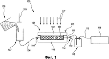
На фиг.1 схематично показана система для осуществления RTM способа.Figure 1 schematically shows a system for implementing the RTM method.
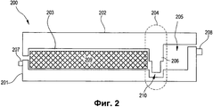
На фиг.2 схематично показано приспособление в соответствии с первым примерным вариантом настоящего изобретения.Figure 2 schematically shows the device in accordance with the first exemplary embodiment of the present invention.
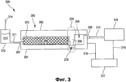
На фиг.3 схематично показана система для осуществления RTM способа.Figure 3 schematically shows a system for implementing the RTM method.
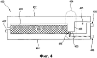
На фиг.4 схематично показано приспособление в соответствии со вторым примерным вариантом настоящего изобретения.4 schematically shows a device in accordance with a second exemplary embodiment of the present invention.
Подробное описание изобретенияDETAILED DESCRIPTION OF THE INVENTION
На фиг.1 схематично показана система 100 для осуществления способа формовки с переносом смолы (RTM способа), которая содержит приспособление 101 с крышкой 102 прессформы и прессформой 103. На фиг.1 также схематично показан компонент 104, который введен в приспособление 101 и который упрочняют за счет использования смолы. Приспособление 101 содержит входной соединитель 105, с которым соединен шланг (труба) 106 с подогревом для смолы, дополнительно соединенный с герметичным контейнером 107, который может быть заполнен предварительно подогретой смолой из транспортного контейнера 108. Более того, система 100 содержит поршень 109 приложения давления, который при вводе в герметичный контейнер 107 создает повышенное давление смолы, находящейся в герметичном контейнере 107, так что она может быть принудительно подана через шланг 106 с подогревом в приспособление 101.1 schematically shows a
Приспособление 101 дополнительно содержит винт 110 для закрывания, при помощи которого приспособление 101 может быть закрыто, то есть при помощи которого крышка 102 прессформы и прессформа 103 могут быть прочно соединены друг с другом. Более того, приспособление содержит выходной соединитель 111, с которым может быть соединен шланг 112 для смолы. Шланг 112 для смолы соединен с ловушкой 113 для смолы и содержит запорный вентиль 114, который используют для закрывания шланга 112 для смолы. Кроме того, ловушка 113 для смолы соединена с вакуумным насосом 116 при помощи воздушного шланга 115.The
RTM способ, который может быть осуществлен с использованием показанной на фиг.1 системы 100, содержит следующие операции способа.The RTM method, which can be implemented using the
Компонент 104, например, упрочняющие волокна, которые разрезаны под размер, вводят в приспособление 101. Затем приспособление 101 закрывают при помощи винта 110 для закрывания и герметизируют. В следующей операции подсоединяют входную трубу 106 для смолы и воздушный шланг 115, при помощи которого создают вакуум. За счет приложения вакуума происходит перенос (перемещение) смолы из внешнего контейнера для хранения, то есть из герметичного контейнера 107, который в этот момент связан с атмосферой, в приспособление 101, где находится компонент 104. Любое закупоривание вакуумного насоса 116 смолой, вытекающей из приспособления 101, исключается за счет внешней ловушки 113 для смолы, которая расположена выше по ходу от вакуумного насоса 116.
В фазе выдержки давления, которая не является обязательной, за счет повышения давления смолы уменьшается размер пор в компоненте. Для этого закрывают запорный вентиль 114, расположенный между приспособлением 101 и ловушкой 113 для смолы, и количество смолы, которая находится в герметичном контейнере 107, сжимают при помощи поршня 109 или при помощи сжатого воздуха. Отверждение смолы, то есть образование поперечных связей в смоле, происходит при подводе теплоты, что схематично показано стрелками 117 на фиг.1. После завершения отверждения удаляют (вынимают) компонент 104. После чистки приспособления 101 в него может быть введен новый компонент.In the pressure holding phase, which is optional, by increasing the pressure of the resin, the pore size in the component decreases. To do this, close the shut-off
Далее со ссылкой на фиг.2 описано приспособление в соответствии с первым примерным вариантом настоящего изобретения. Приспособление 200 содержит прессформу 201 или элемент прессформы (нижнюю часть прессформы) и крышку 202 прессформы (верхнюю часть прессформы), которые (при соединении) образуют первую полость или незаполненное пространство 203, переходную область 204 и вторую полость 205, которая образует ловушку для смолы. В крышке 202 прессформы предусмотрен разделительный элемент 206, который выполнен так, что в переходной области 204 он образует область соединения в виде сифона между полостью 203 и ловушкой 205 для смолы. Для создания этой области соединения в виде сифона или U-образной области соединения, прессформа 201 содержит углубление, в которое частично заходит разделительный элемент 206. В этой схеме построения, введенный в углубление разделительный элемент 206 образует сифон 210.Next, with reference to FIG. 2, a device is described in accordance with a first exemplary embodiment of the present invention. The
Более того, приспособление 200 содержит входной соединитель 207, который соединен с первой полостью 203, причем при помощи входного соединителя 207 смола может быть подана в первую полость 203. Кроме того, приспособление 200 содержит выходной соединитель 208, который соединен с ловушкой 205 для смолы и выполнен так, что его можно соединять с насосом. Более того, на фиг.2 схематично показан компонент 209, обработку которого производят с использованием RTM способа.Moreover, the
Разделительный элемент 206 также может быть выполнен как элемент нижней части 201 приспособления, при этом будет только один соединительный канал между ловушкой 205 для смолы и компонентом 209. Разделительный элемент 206 также может быть выполнен частично как элемент верхней части 202 приспособления и частично как элемент нижней части 201 приспособления.The
Далее со ссылкой на фиг.3 описана система с приспособлением для осуществления RTM способа. Система 300 содержит приспособление 200, показанное на фиг.2, и дополнительно содержит входную трубу 311, которая соединена с входным соединителем 207. Кроме того, входная труба 311 соединена с контейнером 312 для хранения, в котором находится смола 313. В контейнере 312 для хранения может быть создано избыточное давление, например, при помощи поршня 314. Избыточное давление может быть создано, например, при помощи насоса.Next, with reference to figure 3 describes a system with a device for implementing the RTM method. The
Более того, система 300 содержит выходную трубу 315, которая соединена с выходным соединителем 208. Кроме того, выходная труба 315 соединена с насосом 316, который выполнен так, что он может создавать давление в ловушке 205 для смолы при помощи выходной трубы 315. С одной стороны, это давление может быть отрицательным давлением (вакуумом), причем за счет приложения отрицательного давления смола 313 может всасываться из контейнера для хранения 312 через входную трубу 311 в полость 203. С другой стороны, это давление может быть избыточным давлением или противодавлением, которое, когда ловушка для смолы заполнена, не позволяет поступать в нее дополнительной смоле и позволяет создать запорный элемент между полостью 203 и ловушкой 205 для смолы.Moreover, the
Более того, система 300 содержит блок 317 управления, который при помощи первой линии 318 связи соединен с ловушкой 205 для смолы, а при помощи второй линии 319 связи соединен с насосом 316. Блок 317 управления выполнен так, что он контролирует и/или регулирует давление, приложенное к ловушке 205 для смолы. Для этого измеряют давление в ловушке 205 для смолы и, в зависимости от измеренного давления и от желательного давления, блок управления 317 подает сигнал управления на насос 316.Moreover, the
Далее описано, как система, описанная со ссылкой на фиг.3, может быть использована для осуществления RTM способа. Компонент 209, например, упрочняющие волокна, которые разрезаны под размер, вводят в полость 203 приспособления 200. После этого приспособление 200 закрывают и герметизируют. В следующей операции входную трубу 311 для смолы соединяют с входным соединителем 207, и, кроме того, выходную трубу 315, например, воздушный шланг, соединяют с выходным соединителем 208. За счет вакуума, приложенного при помощи воздушного шланга 315, или за счет избыточного давления, приложенного к одной из входных труб 311, смола 313 всасывается, перекачивается или принудительно направляется из внешнего контейнера 312 для хранения в полость 203. При поступлении смолы во внутреннюю ловушку 205 для смолы, в указанной ловушке 205 для смолы создается избыточное давление за счет созданного насосом 316 противодавления, в результате чего дальнейшее поступление смолы в ловушку 205 для смолы снижается или прекращается, так что насос 316 будет защищен от любого поступления в него смолы. После этого, возможно, может быть осуществлена так называемая фаза выдержки давления, во время которой поддерживают избыточное давление в полости, в результате чего размер пор в компоненте 209 уменьшается. Если используют такую фазу выдержки давления, то противодавление, за счет которого создано избыточное давление в ловушке для смолы, регулируют, например, увеличивают, так что уровень смолы в ловушке 205 для смолы остается постоянным. Для этого, в области ловушки 205 для смолы преимущественно закрепляют датчик, который соединен с блоком 317 управления при помощи первой линии 318 связи и подает сигналы измерения на блок управления. При поступлении сигналов измерения, блок управления 317 вырабатывает сигналы управления, которые направляют на насос 316 по второй линии 319 связи, для управления насосом 316.The following describes how the system described with reference to FIG. 3 can be used to implement the RTM method.
Затем происходит отверждение смолы в полости 203. Такое отверждение происходит при подводе теплоты. После завершения отверждения, компонент 209 может быть удален, прессформа 201 может быть очищена и новый компонент может быть введен в нее.Then, the resin cures in the
Далее со ссылкой на фиг.4 описано приспособление в соответствии со вторым примерным вариантом настоящего изобретения. Приспособление 400 содержит прессформу 401 или элемент прессформы и крышку 402 прессформы, которые выполнены так, что они образуют первую полость 403, переходную область 404 и вторую полость 405, которая представляет собой ловушку для смолы. В крышке 402 прессформы предусмотрен разделительный элемент 406, который выполнен так, что в переходной области 204 он создает частичное разделение полости 403 от ловушки 405 для смолы, в результате чего создается соединение 420 между ловушкой 405 для смолы и полостью 403. Внутри этого соединения 420 установлен запорный вентиль или запорный лапан 418, который может перекрывать соединение 420. Указанным образом полость 403 и ловушка 405 для смолы могут быть полностью разъединены друг от друга, при этом смола больше не может поступать из полости 403 в ловушку 405 для смолы или наоборот. Для управления запорным вентилем 418, приспособление 400 дополнительно содержит соединитель 419 управления, при помощи которого сигнал управления может быть подан на запорный вентиль 418. Этот сигнал управления может быть, например, пневматическим и/или электрическим сигналом по своей природе и может быть создан при помощи управляющего элемента.Next, with reference to FIG. 4, a device in accordance with a second exemplary embodiment of the present invention is described. The
Более того, приспособление 400 содержит входной соединитель 407, который соединен с первой полостью 403, причем при помощи указанного входного соединителя 407 смола может быть введена в первую полость 403. Приспособление 400 дополнительно содержит выходной соединитель 408, который соединен с ловушкой для смолы 405 и выполнен так, что он может быть соединен с насосом. На фиг.4 также схематично показан компонент 409, который может быть обработан в RTM способе.Moreover, the
Приспособление 400 в соответствии со вторым примерным вариантом также может быть использовано в системе, которая схематично показана на фиг.3. В соответствии с показанным на фиг.4 примерным вариантом, требуется только соединитель для сжатого воздуха и/или соединитель управления для запорного вентиля, в результате чего не возникают никакие проблемы уплотнения за счет грязи, то есть смола не может вытекать из приспособления за счет загрязненных элементов уплотнения.The
Подводя итог, можно сказать, что в соответствии с примерным аспектом настоящего изобретения предлагается приспособление для осуществления способа формовки с переносом смолы (RTM способа), причем указанное приспособление содержит внутреннюю ловушку для смолы, которая объединена с приспособлением. Другими словами, ловушка для смолы выполнена в виде единого целого с приспособлением. В соответствии со специфическим примерным аспектом настоящего изобретения предлагаются приспособление и система для осуществления RTM способа, причем указанные приспособление и система позволяют исключить необходимость использования (отдельного) запорного элемента или запорного вентиля, который отделяет полость приспособления от ловушки для смолы.To summarize, it can be said that in accordance with an exemplary aspect of the present invention, there is provided an apparatus for implementing a resin transfer molding method (RTM method), said apparatus comprising an internal resin trap that is integrated with the apparatus. In other words, the resin trap is made in one piece with the device. In accordance with a specific exemplary aspect of the present invention, there is provided an apparatus and system for implementing an RTM method, said apparatus and system eliminating the need to use a (separate) shut-off element or shut-off valve that separates the cavity of the tool from the resin trap.
Claims (19)
прессформу (201);
крышку (202) прессформы,
полость (203),
ловушку (205) для смолы,
переходную область (204),
средство создания давления,
причем полость (203) выполнена так, что может быть введен в нее компонент (209),
при этом ловушка (205) для смолы встроена в приспособление (200),
причем переходная область (204) выполнена так, что за счет нее создается соединение между полостью (203) и ловушкой (205) для смолы, и содержит разделительный элемент (206), а средство создания давления позволяет создавать избыточное давление в ловушке (205) для смолы, которая встроена в приспособление (200) и сообщается с полостью (203),
насос (316) и
контейнер (312) для хранения,
причем насос (316) соединен с выходным соединителем (208) ловушки (205)
для смолы, а контейнер для хранения (312) соединен с входным соединителем (311) полости (203).1. System for implementing a method of molding with transfer of resin, which includes
mold (201);
mold cover (202),
cavity (203),
resin trap (205),
transition region (204),
means of creating pressure
moreover, the cavity (203) is designed so that component (209) can be introduced into it,
wherein the resin trap (205) is integrated into the fixture (200),
moreover, the transition region (204) is made so that it creates a connection between the cavity (203) and the trap (205) for the resin, and contains a separation element (206), and the means for creating pressure allows you to create excess pressure in the trap (205) for resin, which is built into the device (200) and communicates with the cavity (203),
pump (316) and
a container (312) for storage,
moreover, the pump (316) is connected to the output connector (208) of the trap (205)
for resin, and the storage container (312) is connected to the inlet connector (311) of the cavity (203).
блок (317) управления, который выполнен так, что он контролирует давление в ловушке (205) для смолы.2. The system according to claim 1, which further comprises
a control unit (317) which is configured to control the pressure in the trap (205) for the resin.
при этом разделительный элемент выполнен так, что управление им производится электрически и/или пневматически.12. The system according to claim 11, in which the control connector (419) is configured such that electrical and / or pneumatic lines are connected with it, and
however, the separation element is designed so that it is controlled electrically and / or pneumatically.
введение компонента (209) в полость (203) системы, по одному из пп.1-15, подачу смолы в полость (203), создание избыточного давления в ловушке (205) для смолы и создание связи с полостью (203) при помощи переходной области (204), которая содержит разделительный элемент (206).16. A method of forming with transfer of resin, which provides
introducing component (209) into the cavity (203) of the system, according to one of claims 1-15, supplying resin to the cavity (203), creating excess pressure in the trap (205) for the resin and creating a connection with the cavity (203) using a transition area (204), which contains the separation element (206).
увеличение давления в ловушке (205) для смолы таким образом, что уровень смолы в ловушке (205) для смолы остается постоянным.17. The method according to clause 16, which further provides
increasing the pressure in the trap (205) for the resin so that the level of resin in the trap (205) for the resin remains constant.
прессформу (201);
крышку (202) прессформы,
полость (203),
ловушку (205) для смолы,
переходную область (204),
средство создания давления,
причем полость (203) выполнена так, что может быть введен в нее компонент (209),
при этом ловушка (205) для смолы встроена в приспособление (200),
причем переходная область (204) выполнена так, что за счет нее создается соединение между полостью (203) и ловушкой (205) для смолы, и содержит разделительный элемент (206), а средство создания давления позволяет создавать избыточное давление в ловушке (205) для смолы, которая встроена в приспособление (200) и сообщается с полостью (203), при этом разделительный элемент представляет собой запорный вентиль (418). 19. A device (200) for implementing a method of molding with transfer of resin, which includes
mold (201);
mold cover (202),
cavity (203),
resin trap (205),
transition region (204),
means of creating pressure
moreover, the cavity (203) is designed so that component (209) can be introduced into it,
wherein the resin trap (205) is integrated into the fixture (200),
moreover, the transition region (204) is made so that it creates a connection between the cavity (203) and the trap (205) for the resin, and contains a separation element (206), and the means for creating pressure allows you to create excess pressure in the trap (205) for resin, which is integrated in the device (200) and communicates with the cavity (203), while the separation element is a shut-off valve (418).
Applications Claiming Priority (2)
| Application Number | Priority Date | Filing Date | Title |
|---|---|---|---|
| DE102005053691A DE102005053691A1 (en) | 2005-11-10 | 2005-11-10 | Tool for resin transfer molding process |
| DE102005053691.3 | 2005-11-10 |
Publications (2)
| Publication Number | Publication Date |
|---|---|
| RU2008123170A RU2008123170A (en) | 2009-12-20 |
| RU2425751C2 true RU2425751C2 (en) | 2011-08-10 |
Family
ID=37546650
Family Applications (1)
| Application Number | Title | Priority Date | Filing Date |
|---|---|---|---|
| RU2008123170/05A RU2425751C2 (en) | 2005-11-10 | 2006-11-07 | Device, system and procedure for moulding with transfer of resin |
Country Status (9)
| Country | Link |
|---|---|
| US (1) | US8858218B2 (en) |
| EP (1) | EP1954476B1 (en) |
| JP (1) | JP5173824B2 (en) |
| CN (1) | CN101304868B (en) |
| BR (1) | BRPI0618314A2 (en) |
| CA (1) | CA2627044A1 (en) |
| DE (2) | DE102005053691A1 (en) |
| RU (1) | RU2425751C2 (en) |
| WO (1) | WO2007054268A1 (en) |
Cited By (4)
| Publication number | Priority date | Publication date | Assignee | Title |
|---|---|---|---|---|
| RU2616066C2 (en) * | 2011-11-08 | 2017-04-12 | Снекма | Pressure holding device for manufacture of composite parts by resin injection and appropriate method |
| RU192485U1 (en) * | 2018-11-26 | 2019-09-18 | Общество с ограниченной ответственностью "Газовоздушные технологии" | Vacuum Infusion Unit |
| RU193346U1 (en) * | 2019-08-25 | 2019-10-24 | Общество с ограниченной ответственностью "Газовоздушные технологии" | Vacuum unit for the vacuum infusion process |
| RU228318U1 (en) * | 2024-05-03 | 2024-08-22 | Федеральное государственное бюджетное образовательное учреждение высшего образования "Тихоокеанский государственный университет" | Vacuum infusion unit |
Families Citing this family (23)
| Publication number | Priority date | Publication date | Assignee | Title |
|---|---|---|---|---|
| DE102009017512A1 (en) | 2009-04-15 | 2010-10-28 | Airbus Deutschland Gmbh | Producing a composite component |
| US7939011B2 (en) * | 2009-08-14 | 2011-05-10 | The Boeing Company | Resin containment and injection system and method |
| DE202010007931U1 (en) | 2010-06-29 | 2011-10-07 | First Composites Gmbh | Apparatus for carrying out a resin transfer molding (RTM) process |
| FR2975629A1 (en) * | 2011-05-27 | 2012-11-30 | Snecma | PRESSURE HOLDING DEVICE FOR PRODUCING COMPOSITE COMPONENTS BY RESIN INJECTION AND ASSOCIATED METHOD |
| DE102011083688A1 (en) | 2011-09-29 | 2013-04-04 | Zf Friedrichshafen Ag | Molding tool for manufacturing fiber-reinforced plastic components, has first mold and third mold which are adapted to form one cavity, and second mold and fourth mold are adapted to form other cavity for producing plastic component |
| DE102011055547A1 (en) * | 2011-11-21 | 2013-05-23 | Deutsches Zentrum für Luft- und Raumfahrt e.V. | Mold for producing a fiber composite component |
| FR2986179B1 (en) * | 2012-01-31 | 2014-10-10 | Techni Modul Engineering | DEVICE AND METHOD FOR MANUFACTURING A MOLDED PIECE OF A COMPOSITE MATERIAL |
| GB2500601B (en) * | 2012-03-26 | 2014-10-22 | Gurit Uk Ltd | Press moulding apparatus and method |
| US20130270729A1 (en) * | 2012-04-12 | 2013-10-17 | Karsten Schibsbye | Resin flow control in vartm process |
| DE102012103668A1 (en) * | 2012-04-26 | 2013-10-31 | Hedrich Gmbh | Reservoir for casting resin and method and apparatus for casting resin |
| DE102012216830A1 (en) * | 2012-09-19 | 2014-03-20 | Wobben Properties Gmbh | Process for the production of wind turbine rotor blades, and for the production of a mandrel for this purpose |
| DE102012110307B4 (en) | 2012-10-29 | 2020-01-23 | Kraussmaffei Technologies Gmbh | Process for the production of composite material components made of plastic by high-pressure resin transfer presses and associated high-pressure resin transfer press tool |
| DE102014215775A1 (en) * | 2014-08-08 | 2016-02-11 | Bayerische Motoren Werke Aktiengesellschaft | Apparatus and process for the production of fiber reinforced components |
| DE202015104694U1 (en) | 2015-09-03 | 2016-11-04 | Dieffenbacher GmbH Maschinen- und Anlagenbau | Control means and mold for producing a fiber-reinforced plastic component |
| DE102015114777A1 (en) | 2015-09-03 | 2017-03-09 | Dieffenbacher GmbH Maschinen- und Anlagenbau | Method, control means and mold for producing a fiber-reinforced plastic component |
| FR3048634B1 (en) * | 2016-03-11 | 2018-04-06 | Safran Aircraft Engines | DEVICE AND METHOD FOR INJECTION MOLDING A LIQUID POLYMER |
| GB2583354B (en) * | 2019-04-24 | 2021-12-29 | Passi Kiren | Composite mould and related aspects |
| RU2711184C1 (en) * | 2019-08-25 | 2020-01-15 | Общество с ограниченной ответственностью "Газовоздушные технологии" | Vacuum installation for vacuum infusion process |
| FR3101571A1 (en) * | 2019-10-07 | 2021-04-09 | Safran | COMPOSITE PART MANUFACTURING PLANT, IN PARTICULAR FOR AN AIRCRAFT ENGINE |
| US12515385B2 (en) | 2021-12-21 | 2026-01-06 | Composite Technologies International, Llc | Apparatus and method for making molded products |
| US11787094B1 (en) * | 2021-12-21 | 2023-10-17 | Composite Technologies International, Llc | Apparatus and method for making molded products |
| EP4463299A1 (en) * | 2022-01-14 | 2024-11-20 | Invibio Device Component Manufacturing Limited | A mould tool |
| IT202200025977A1 (en) * | 2022-12-19 | 2024-06-19 | Univ Degli Studi Di Salerno | ADAPTIVE PLANT AND METHOD FOR THE PRODUCTION OF THERMOSETTING MATRIX COMPOSITES |
Citations (8)
| Publication number | Priority date | Publication date | Assignee | Title |
|---|---|---|---|---|
| GB1008136A (en) * | 1963-05-31 | 1965-10-27 | Reichhold Chemie Ag | Improvements in or relating to moulding of reinforced plastics articles |
| US3970732A (en) * | 1973-09-26 | 1976-07-20 | Kimball International, Inc. | Method of molding rigid foamed polyurethane articles |
| GB1462623A (en) * | 1973-02-20 | 1977-01-26 | Clearex Plastics Ltd | Vacuum moulding |
| EP0230709A2 (en) * | 1986-01-21 | 1987-08-05 | Group Lotus Plc | Mould for moulding an article |
| US5023041A (en) * | 1987-12-10 | 1991-06-11 | General Electric Company | Method for making a fiber reinforced composite article |
| RU2080750C1 (en) * | 1986-09-15 | 1997-05-27 | Композитек, Лтд. | Armored multiple-layer plastic materials for manufacturing of printed circuits, methods for manufacturing of such materials and resulted devices |
| FR2771960A1 (en) * | 1997-12-09 | 1999-06-11 | Eurocopter France | Plant molding fibre-reinforced plastic by injection under vacuum |
| RU2201343C2 (en) * | 2001-05-29 | 2003-03-27 | Открытое акционерное общество Научно-производственное объединение "Искра" | Method of manufacture of articles from composite materials |
Family Cites Families (14)
| Publication number | Priority date | Publication date | Assignee | Title |
|---|---|---|---|---|
| GB791552A (en) | 1954-11-10 | 1958-03-05 | Norman Whitaker Wright | Improvements in or relating to the moulding of fibrous material |
| JPS60225721A (en) * | 1984-04-25 | 1985-11-11 | Sumitomo Bakelite Co Ltd | Preparation of precise molded article |
| JPS61144313A (en) * | 1984-12-19 | 1986-07-02 | Sumitomo Bakelite Co Ltd | Manufacture of precise molded article |
| EP0320302A3 (en) * | 1987-12-10 | 1992-01-02 | General Electric Company | Method and apparatus for making a fiber reinforced composite article |
| JPH0631755A (en) | 1992-07-14 | 1994-02-08 | Nippo Sangyo Kk | Cast molding equipment for reaction-curable synthetic resins |
| JP2593772B2 (en) | 1992-09-01 | 1997-03-26 | 川崎重工業株式会社 | Manufacturing method for composite products |
| DE19630840C1 (en) | 1996-07-31 | 1998-02-12 | Kilian Saueressig | Production of hollow reinforced mouldings by push-pull saturation |
| US5863452A (en) * | 1997-04-17 | 1999-01-26 | Northrop Grumman Corporation | Isostatic pressure resin transfer molding |
| JP2002160224A (en) * | 2000-11-27 | 2002-06-04 | Sumitomo Chem Co Ltd | Mold for producing lightweight thermoplastic resin article and method for producing lightweight thermoplastic resin article using the same |
| DE10059132A1 (en) * | 2000-11-29 | 2002-06-20 | Basf Ag | Component coating tool for furniture or vehicle interior components includes a component-holding cavity with a coating chamber and a coating feed line from a reservoir in a tool sealing face |
| US7147818B1 (en) * | 2002-05-16 | 2006-12-12 | The United States Of America As Represented By The Secretary Of The Army | Process and apparatus for improved composite fiber volume fraction and dimensional stability by removal of accumulated excess resin using the vacuum assisted resin transfer molding (VARTM) process |
| US6855283B2 (en) * | 2002-07-25 | 2005-02-15 | Patent Holdings Company | Method for forming a sheet, fiber and resin composite |
| JP4292971B2 (en) | 2003-12-10 | 2009-07-08 | 東レ株式会社 | FRP manufacturing method and manufacturing apparatus |
| JP4016013B2 (en) * | 2004-05-10 | 2007-12-05 | 本田技研工業株式会社 | Method for producing laminated molded product |
-
2005
- 2005-11-10 DE DE102005053691A patent/DE102005053691A1/en not_active Withdrawn
-
2006
- 2006-11-07 CA CA002627044A patent/CA2627044A1/en not_active Abandoned
- 2006-11-07 WO PCT/EP2006/010660 patent/WO2007054268A1/en not_active Ceased
- 2006-11-07 EP EP06828945A patent/EP1954476B1/en not_active Not-in-force
- 2006-11-07 BR BRPI0618314-0A patent/BRPI0618314A2/en not_active IP Right Cessation
- 2006-11-07 DE DE602006020166T patent/DE602006020166D1/en active Active
- 2006-11-07 JP JP2008539324A patent/JP5173824B2/en not_active Expired - Fee Related
- 2006-11-07 RU RU2008123170/05A patent/RU2425751C2/en not_active IP Right Cessation
- 2006-11-07 US US12/084,727 patent/US8858218B2/en active Active
- 2006-11-07 CN CN200680041554.XA patent/CN101304868B/en not_active Expired - Fee Related
Patent Citations (8)
| Publication number | Priority date | Publication date | Assignee | Title |
|---|---|---|---|---|
| GB1008136A (en) * | 1963-05-31 | 1965-10-27 | Reichhold Chemie Ag | Improvements in or relating to moulding of reinforced plastics articles |
| GB1462623A (en) * | 1973-02-20 | 1977-01-26 | Clearex Plastics Ltd | Vacuum moulding |
| US3970732A (en) * | 1973-09-26 | 1976-07-20 | Kimball International, Inc. | Method of molding rigid foamed polyurethane articles |
| EP0230709A2 (en) * | 1986-01-21 | 1987-08-05 | Group Lotus Plc | Mould for moulding an article |
| RU2080750C1 (en) * | 1986-09-15 | 1997-05-27 | Композитек, Лтд. | Armored multiple-layer plastic materials for manufacturing of printed circuits, methods for manufacturing of such materials and resulted devices |
| US5023041A (en) * | 1987-12-10 | 1991-06-11 | General Electric Company | Method for making a fiber reinforced composite article |
| FR2771960A1 (en) * | 1997-12-09 | 1999-06-11 | Eurocopter France | Plant molding fibre-reinforced plastic by injection under vacuum |
| RU2201343C2 (en) * | 2001-05-29 | 2003-03-27 | Открытое акционерное общество Научно-производственное объединение "Искра" | Method of manufacture of articles from composite materials |
Cited By (5)
| Publication number | Priority date | Publication date | Assignee | Title |
|---|---|---|---|---|
| RU2616066C2 (en) * | 2011-11-08 | 2017-04-12 | Снекма | Pressure holding device for manufacture of composite parts by resin injection and appropriate method |
| RU192485U1 (en) * | 2018-11-26 | 2019-09-18 | Общество с ограниченной ответственностью "Газовоздушные технологии" | Vacuum Infusion Unit |
| RU193346U1 (en) * | 2019-08-25 | 2019-10-24 | Общество с ограниченной ответственностью "Газовоздушные технологии" | Vacuum unit for the vacuum infusion process |
| RU228318U1 (en) * | 2024-05-03 | 2024-08-22 | Федеральное государственное бюджетное образовательное учреждение высшего образования "Тихоокеанский государственный университет" | Vacuum infusion unit |
| RU2851910C1 (en) * | 2025-06-05 | 2025-12-01 | Общество с ограниченной ответственностью "УралАктив" | Method for manufacturing fan housing from fibreglass using vacuum |
Also Published As
| Publication number | Publication date |
|---|---|
| US20100019405A1 (en) | 2010-01-28 |
| DE602006020166D1 (en) | 2011-03-31 |
| JP5173824B2 (en) | 2013-04-03 |
| WO2007054268A1 (en) | 2007-05-18 |
| RU2008123170A (en) | 2009-12-20 |
| DE102005053691A1 (en) | 2007-05-16 |
| US8858218B2 (en) | 2014-10-14 |
| EP1954476A1 (en) | 2008-08-13 |
| JP2009514705A (en) | 2009-04-09 |
| CN101304868B (en) | 2010-10-13 |
| CN101304868A (en) | 2008-11-12 |
| EP1954476B1 (en) | 2011-02-16 |
| BRPI0618314A2 (en) | 2011-08-23 |
| CA2627044A1 (en) | 2007-05-18 |
Similar Documents
| Publication | Publication Date | Title |
|---|---|---|
| RU2425751C2 (en) | Device, system and procedure for moulding with transfer of resin | |
| US20250010558A1 (en) | System and method for resin transfer moulding | |
| CN101585238B (en) | Integral Forming Technology and Forming System of Super Large Composite Components | |
| CN103521105B (en) | A kind of automotive fluid proportioning control system of proportion adjustable and control method thereof | |
| RU2423237C2 (en) | Appliance, system and method of producing composite components | |
| JP5754721B2 (en) | Systems and methods for resin containment and injection | |
| CN107825728A (en) | For producing the method and infusion apparatus of the body made of enhancing composite | |
| CN108493391A (en) | Coolant injection system, device and method for battery cooling system | |
| CN102514142A (en) | Quantitative glue injection device of high-temperature resin transfer mold | |
| CN111284041A (en) | Glue injection equipment and process for glue solution circulation | |
| CN111479620B (en) | Material conveying equipment and material conveying method thereof | |
| US20220176631A1 (en) | Feeding devices and 3d printing apparatuses | |
| CN207008150U (en) | Optical cable core gel filling device | |
| CN108480150A (en) | Into adhesive dispenser, into the gentle hydraulic control tubing giving sufficient strength system of gluing method | |
| CN211730332U (en) | Vacuum flow guiding device | |
| CN121132982B (en) | Pinhole cable glue filling equipment and filling method of motor train unit brake control system | |
| CN115592841A (en) | An online integrated rubber mixing and filling system and filling process for non-excavation repair hose | |
| CN208297781U (en) | Fiber optic connector assembly and optical fiber connector tail sleeve | |
| CN210022075U (en) | Solid-liquid reaction automatic metering equipment | |
| CN111231368A (en) | Vacuum guiding device and vacuum guiding method | |
| CN207488551U (en) | Prepare optical fiber connector tail sleeve prepares mold | |
| CN106042416B (en) | Vacuum material injection method | |
| CN207005568U (en) | Briquetting roller negative pressure system cleaning device anti-clogging installing pipe | |
| CN204454518U (en) | A kind of suction type dosing filling machine | |
| CN216880173U (en) | Automatic feeding limiting device |
Legal Events
| Date | Code | Title | Description |
|---|---|---|---|
| PD4A | Correction of name of patent owner | ||
| MM4A | The patent is invalid due to non-payment of fees |
Effective date: 20171108 |