RU2424918C2 - Hybrid transport facility and transport facility - Google Patents
Hybrid transport facility and transport facility Download PDFInfo
- Publication number
- RU2424918C2 RU2424918C2 RU2009129684/11A RU2009129684A RU2424918C2 RU 2424918 C2 RU2424918 C2 RU 2424918C2 RU 2009129684/11 A RU2009129684/11 A RU 2009129684/11A RU 2009129684 A RU2009129684 A RU 2009129684A RU 2424918 C2 RU2424918 C2 RU 2424918C2
- Authority
- RU
- Russia
- Prior art keywords
- unit
- vehicle
- energy
- power
- supplied
- Prior art date
Links
- 239000002828 fuel tank Substances 0.000 claims abstract description 16
- 239000000446 fuel Substances 0.000 claims description 87
- 239000001257 hydrogen Substances 0.000 claims description 51
- 229910052739 hydrogen Inorganic materials 0.000 claims description 51
- UFHFLCQGNIYNRP-UHFFFAOYSA-N Hydrogen Chemical compound [H][H] UFHFLCQGNIYNRP-UHFFFAOYSA-N 0.000 claims description 44
- 238000003860 storage Methods 0.000 claims description 34
- 230000007935 neutral effect Effects 0.000 claims description 33
- 230000005611 electricity Effects 0.000 claims description 26
- 238000004146 energy storage Methods 0.000 claims description 23
- 238000004804 winding Methods 0.000 claims description 16
- 238000002485 combustion reaction Methods 0.000 claims description 9
- 125000004435 hydrogen atom Chemical group [H]* 0.000 claims description 7
- 150000002431 hydrogen Chemical class 0.000 claims description 3
- 235000019577 caloric intake Nutrition 0.000 claims 1
- 238000006073 displacement reaction Methods 0.000 claims 1
- 239000006163 transport media Substances 0.000 claims 1
- 230000004308 accommodation Effects 0.000 abstract description 3
- 230000037452 priming Effects 0.000 abstract 4
- 238000009825 accumulation Methods 0.000 abstract 3
- 229930002839 ionone Natural products 0.000 abstract 1
- 150000002499 ionone derivatives Chemical class 0.000 abstract 1
- 239000000126 substance Substances 0.000 abstract 1
- OKKJLVBELUTLKV-UHFFFAOYSA-N Methanol Chemical compound OC OKKJLVBELUTLKV-UHFFFAOYSA-N 0.000 description 51
- LFQSCWFLJHTTHZ-UHFFFAOYSA-N Ethanol Chemical compound CCO LFQSCWFLJHTTHZ-UHFFFAOYSA-N 0.000 description 24
- 238000000034 method Methods 0.000 description 22
- 239000003990 capacitor Substances 0.000 description 20
- 238000010586 diagram Methods 0.000 description 9
- XLYOFNOQVPJJNP-UHFFFAOYSA-N water Substances O XLYOFNOQVPJJNP-UHFFFAOYSA-N 0.000 description 9
- 230000001172 regenerating effect Effects 0.000 description 8
- 238000009826 distribution Methods 0.000 description 7
- 230000004048 modification Effects 0.000 description 6
- 238000012986 modification Methods 0.000 description 6
- 238000002407 reforming Methods 0.000 description 6
- CURLTUGMZLYLDI-UHFFFAOYSA-N Carbon dioxide Chemical compound O=C=O CURLTUGMZLYLDI-UHFFFAOYSA-N 0.000 description 4
- 238000010276 construction Methods 0.000 description 3
- 230000006866 deterioration Effects 0.000 description 3
- 230000035939 shock Effects 0.000 description 3
- 210000001364 upper extremity Anatomy 0.000 description 3
- 101150049032 ACL1 gene Proteins 0.000 description 2
- 101100448894 Arabidopsis thaliana GLR3.1 gene Proteins 0.000 description 2
- 101100054598 Hordeum vulgare ACL1.2 gene Proteins 0.000 description 2
- 238000010521 absorption reaction Methods 0.000 description 2
- 230000001133 acceleration Effects 0.000 description 2
- 101150023061 acpP gene Proteins 0.000 description 2
- QVGXLLKOCUKJST-UHFFFAOYSA-N atomic oxygen Chemical compound [O] QVGXLLKOCUKJST-UHFFFAOYSA-N 0.000 description 2
- 230000015572 biosynthetic process Effects 0.000 description 2
- 229910002092 carbon dioxide Inorganic materials 0.000 description 2
- 239000001569 carbon dioxide Substances 0.000 description 2
- 239000000498 cooling water Substances 0.000 description 2
- 230000007797 corrosion Effects 0.000 description 2
- 238000005260 corrosion Methods 0.000 description 2
- 239000003085 diluting agent Substances 0.000 description 2
- 239000007789 gas Substances 0.000 description 2
- 239000003502 gasoline Substances 0.000 description 2
- 230000005484 gravity Effects 0.000 description 2
- -1 hydrogen ions Chemical class 0.000 description 2
- 239000001301 oxygen Substances 0.000 description 2
- 229910052760 oxygen Inorganic materials 0.000 description 2
- BASFCYQUMIYNBI-UHFFFAOYSA-N platinum Chemical compound [Pt] BASFCYQUMIYNBI-UHFFFAOYSA-N 0.000 description 2
- HBBGRARXTFLTSG-UHFFFAOYSA-N Lithium ion Chemical compound [Li+] HBBGRARXTFLTSG-UHFFFAOYSA-N 0.000 description 1
- PXHVJJICTQNCMI-UHFFFAOYSA-N Nickel Chemical compound [Ni] PXHVJJICTQNCMI-UHFFFAOYSA-N 0.000 description 1
- 229910045601 alloy Inorganic materials 0.000 description 1
- 239000000956 alloy Substances 0.000 description 1
- INJRKJPEYSAMPD-UHFFFAOYSA-N aluminum;silicic acid;hydrate Chemical compound O.[Al].[Al].O[Si](O)(O)O INJRKJPEYSAMPD-UHFFFAOYSA-N 0.000 description 1
- 230000005540 biological transmission Effects 0.000 description 1
- 239000003054 catalyst Substances 0.000 description 1
- 238000006243 chemical reaction Methods 0.000 description 1
- 239000002131 composite material Substances 0.000 description 1
- 238000001035 drying Methods 0.000 description 1
- 238000005516 engineering process Methods 0.000 description 1
- 239000000284 extract Substances 0.000 description 1
- 230000001939 inductive effect Effects 0.000 description 1
- 238000009434 installation Methods 0.000 description 1
- 239000007788 liquid Substances 0.000 description 1
- 229910001416 lithium ion Inorganic materials 0.000 description 1
- 238000004519 manufacturing process Methods 0.000 description 1
- 229910000652 nickel hydride Inorganic materials 0.000 description 1
- 229910052697 platinum Inorganic materials 0.000 description 1
- 238000010248 power generation Methods 0.000 description 1
- 238000011084 recovery Methods 0.000 description 1
Images


Classifications
-
- B—PERFORMING OPERATIONS; TRANSPORTING
- B60—VEHICLES IN GENERAL
- B60K—ARRANGEMENT OR MOUNTING OF PROPULSION UNITS OR OF TRANSMISSIONS IN VEHICLES; ARRANGEMENT OR MOUNTING OF PLURAL DIVERSE PRIME-MOVERS IN VEHICLES; AUXILIARY DRIVES FOR VEHICLES; INSTRUMENTATION OR DASHBOARDS FOR VEHICLES; ARRANGEMENTS IN CONNECTION WITH COOLING, AIR INTAKE, GAS EXHAUST OR FUEL SUPPLY OF PROPULSION UNITS IN VEHICLES
- B60K6/00—Arrangement or mounting of plural diverse prime-movers for mutual or common propulsion, e.g. hybrid propulsion systems comprising electric motors and internal combustion engines ; Control systems therefor, i.e. systems controlling two or more prime movers, or controlling one of these prime movers and any of the transmission, drive or drive units Informative references: mechanical gearings with secondary electric drive F16H3/72; arrangements for handling mechanical energy structurally associated with the dynamo-electric machine H02K7/00; machines comprising structurally interrelated motor and generator parts H02K51/00; dynamo-electric machines not otherwise provided for in H02K see H02K99/00
- B60K6/20—Arrangement or mounting of plural diverse prime-movers for mutual or common propulsion, e.g. hybrid propulsion systems comprising electric motors and internal combustion engines ; Control systems therefor, i.e. systems controlling two or more prime movers, or controlling one of these prime movers and any of the transmission, drive or drive units Informative references: mechanical gearings with secondary electric drive F16H3/72; arrangements for handling mechanical energy structurally associated with the dynamo-electric machine H02K7/00; machines comprising structurally interrelated motor and generator parts H02K51/00; dynamo-electric machines not otherwise provided for in H02K see H02K99/00 the prime-movers consisting of electric motors and internal combustion engines, e.g. HEVs
- B60K6/42—Arrangement or mounting of plural diverse prime-movers for mutual or common propulsion, e.g. hybrid propulsion systems comprising electric motors and internal combustion engines ; Control systems therefor, i.e. systems controlling two or more prime movers, or controlling one of these prime movers and any of the transmission, drive or drive units Informative references: mechanical gearings with secondary electric drive F16H3/72; arrangements for handling mechanical energy structurally associated with the dynamo-electric machine H02K7/00; machines comprising structurally interrelated motor and generator parts H02K51/00; dynamo-electric machines not otherwise provided for in H02K see H02K99/00 the prime-movers consisting of electric motors and internal combustion engines, e.g. HEVs characterised by the architecture of the hybrid electric vehicle
- B60K6/44—Series-parallel type
- B60K6/445—Differential gearing distribution type
-
- B—PERFORMING OPERATIONS; TRANSPORTING
- B60—VEHICLES IN GENERAL
- B60K—ARRANGEMENT OR MOUNTING OF PROPULSION UNITS OR OF TRANSMISSIONS IN VEHICLES; ARRANGEMENT OR MOUNTING OF PLURAL DIVERSE PRIME-MOVERS IN VEHICLES; AUXILIARY DRIVES FOR VEHICLES; INSTRUMENTATION OR DASHBOARDS FOR VEHICLES; ARRANGEMENTS IN CONNECTION WITH COOLING, AIR INTAKE, GAS EXHAUST OR FUEL SUPPLY OF PROPULSION UNITS IN VEHICLES
- B60K15/00—Arrangement in connection with fuel supply of combustion engines or other fuel consuming energy converters, e.g. fuel cells; Mounting or construction of fuel tanks
- B60K15/03—Fuel tanks
- B60K15/04—Tank inlets
-
- B—PERFORMING OPERATIONS; TRANSPORTING
- B60—VEHICLES IN GENERAL
- B60K—ARRANGEMENT OR MOUNTING OF PROPULSION UNITS OR OF TRANSMISSIONS IN VEHICLES; ARRANGEMENT OR MOUNTING OF PLURAL DIVERSE PRIME-MOVERS IN VEHICLES; AUXILIARY DRIVES FOR VEHICLES; INSTRUMENTATION OR DASHBOARDS FOR VEHICLES; ARRANGEMENTS IN CONNECTION WITH COOLING, AIR INTAKE, GAS EXHAUST OR FUEL SUPPLY OF PROPULSION UNITS IN VEHICLES
- B60K6/00—Arrangement or mounting of plural diverse prime-movers for mutual or common propulsion, e.g. hybrid propulsion systems comprising electric motors and internal combustion engines ; Control systems therefor, i.e. systems controlling two or more prime movers, or controlling one of these prime movers and any of the transmission, drive or drive units Informative references: mechanical gearings with secondary electric drive F16H3/72; arrangements for handling mechanical energy structurally associated with the dynamo-electric machine H02K7/00; machines comprising structurally interrelated motor and generator parts H02K51/00; dynamo-electric machines not otherwise provided for in H02K see H02K99/00
- B60K6/20—Arrangement or mounting of plural diverse prime-movers for mutual or common propulsion, e.g. hybrid propulsion systems comprising electric motors and internal combustion engines ; Control systems therefor, i.e. systems controlling two or more prime movers, or controlling one of these prime movers and any of the transmission, drive or drive units Informative references: mechanical gearings with secondary electric drive F16H3/72; arrangements for handling mechanical energy structurally associated with the dynamo-electric machine H02K7/00; machines comprising structurally interrelated motor and generator parts H02K51/00; dynamo-electric machines not otherwise provided for in H02K see H02K99/00 the prime-movers consisting of electric motors and internal combustion engines, e.g. HEVs
- B60K6/22—Arrangement or mounting of plural diverse prime-movers for mutual or common propulsion, e.g. hybrid propulsion systems comprising electric motors and internal combustion engines ; Control systems therefor, i.e. systems controlling two or more prime movers, or controlling one of these prime movers and any of the transmission, drive or drive units Informative references: mechanical gearings with secondary electric drive F16H3/72; arrangements for handling mechanical energy structurally associated with the dynamo-electric machine H02K7/00; machines comprising structurally interrelated motor and generator parts H02K51/00; dynamo-electric machines not otherwise provided for in H02K see H02K99/00 the prime-movers consisting of electric motors and internal combustion engines, e.g. HEVs characterised by apparatus, components or means specially adapted for HEVs
- B60K6/28—Arrangement or mounting of plural diverse prime-movers for mutual or common propulsion, e.g. hybrid propulsion systems comprising electric motors and internal combustion engines ; Control systems therefor, i.e. systems controlling two or more prime movers, or controlling one of these prime movers and any of the transmission, drive or drive units Informative references: mechanical gearings with secondary electric drive F16H3/72; arrangements for handling mechanical energy structurally associated with the dynamo-electric machine H02K7/00; machines comprising structurally interrelated motor and generator parts H02K51/00; dynamo-electric machines not otherwise provided for in H02K see H02K99/00 the prime-movers consisting of electric motors and internal combustion engines, e.g. HEVs characterised by apparatus, components or means specially adapted for HEVs characterised by the electric energy storing means, e.g. batteries or capacitors
-
- B—PERFORMING OPERATIONS; TRANSPORTING
- B60—VEHICLES IN GENERAL
- B60L—PROPULSION OF ELECTRICALLY-PROPELLED VEHICLES; SUPPLYING ELECTRIC POWER FOR AUXILIARY EQUIPMENT OF ELECTRICALLY-PROPELLED VEHICLES; ELECTRODYNAMIC BRAKE SYSTEMS FOR VEHICLES IN GENERAL; MAGNETIC SUSPENSION OR LEVITATION FOR VEHICLES; MONITORING OPERATING VARIABLES OF ELECTRICALLY-PROPELLED VEHICLES; ELECTRIC SAFETY DEVICES FOR ELECTRICALLY-PROPELLED VEHICLES
- B60L15/00—Methods, circuits, or devices for controlling the traction-motor speed of electrically-propelled vehicles
- B60L15/007—Physical arrangements or structures of drive train converters specially adapted for the propulsion motors of electric vehicles
-
- B—PERFORMING OPERATIONS; TRANSPORTING
- B60—VEHICLES IN GENERAL
- B60L—PROPULSION OF ELECTRICALLY-PROPELLED VEHICLES; SUPPLYING ELECTRIC POWER FOR AUXILIARY EQUIPMENT OF ELECTRICALLY-PROPELLED VEHICLES; ELECTRODYNAMIC BRAKE SYSTEMS FOR VEHICLES IN GENERAL; MAGNETIC SUSPENSION OR LEVITATION FOR VEHICLES; MONITORING OPERATING VARIABLES OF ELECTRICALLY-PROPELLED VEHICLES; ELECTRIC SAFETY DEVICES FOR ELECTRICALLY-PROPELLED VEHICLES
- B60L50/00—Electric propulsion with power supplied within the vehicle
- B60L50/10—Electric propulsion with power supplied within the vehicle using propulsion power supplied by engine-driven generators, e.g. generators driven by combustion engines
- B60L50/16—Electric propulsion with power supplied within the vehicle using propulsion power supplied by engine-driven generators, e.g. generators driven by combustion engines with provision for separate direct mechanical propulsion
-
- B—PERFORMING OPERATIONS; TRANSPORTING
- B60—VEHICLES IN GENERAL
- B60L—PROPULSION OF ELECTRICALLY-PROPELLED VEHICLES; SUPPLYING ELECTRIC POWER FOR AUXILIARY EQUIPMENT OF ELECTRICALLY-PROPELLED VEHICLES; ELECTRODYNAMIC BRAKE SYSTEMS FOR VEHICLES IN GENERAL; MAGNETIC SUSPENSION OR LEVITATION FOR VEHICLES; MONITORING OPERATING VARIABLES OF ELECTRICALLY-PROPELLED VEHICLES; ELECTRIC SAFETY DEVICES FOR ELECTRICALLY-PROPELLED VEHICLES
- B60L50/00—Electric propulsion with power supplied within the vehicle
- B60L50/50—Electric propulsion with power supplied within the vehicle using propulsion power supplied by batteries or fuel cells
- B60L50/60—Electric propulsion with power supplied within the vehicle using propulsion power supplied by batteries or fuel cells using power supplied by batteries
- B60L50/61—Electric propulsion with power supplied within the vehicle using propulsion power supplied by batteries or fuel cells using power supplied by batteries by batteries charged by engine-driven generators, e.g. series hybrid electric vehicles
-
- B—PERFORMING OPERATIONS; TRANSPORTING
- B60—VEHICLES IN GENERAL
- B60L—PROPULSION OF ELECTRICALLY-PROPELLED VEHICLES; SUPPLYING ELECTRIC POWER FOR AUXILIARY EQUIPMENT OF ELECTRICALLY-PROPELLED VEHICLES; ELECTRODYNAMIC BRAKE SYSTEMS FOR VEHICLES IN GENERAL; MAGNETIC SUSPENSION OR LEVITATION FOR VEHICLES; MONITORING OPERATING VARIABLES OF ELECTRICALLY-PROPELLED VEHICLES; ELECTRIC SAFETY DEVICES FOR ELECTRICALLY-PROPELLED VEHICLES
- B60L50/00—Electric propulsion with power supplied within the vehicle
- B60L50/50—Electric propulsion with power supplied within the vehicle using propulsion power supplied by batteries or fuel cells
- B60L50/60—Electric propulsion with power supplied within the vehicle using propulsion power supplied by batteries or fuel cells using power supplied by batteries
- B60L50/66—Arrangements of batteries
-
- B—PERFORMING OPERATIONS; TRANSPORTING
- B60—VEHICLES IN GENERAL
- B60L—PROPULSION OF ELECTRICALLY-PROPELLED VEHICLES; SUPPLYING ELECTRIC POWER FOR AUXILIARY EQUIPMENT OF ELECTRICALLY-PROPELLED VEHICLES; ELECTRODYNAMIC BRAKE SYSTEMS FOR VEHICLES IN GENERAL; MAGNETIC SUSPENSION OR LEVITATION FOR VEHICLES; MONITORING OPERATING VARIABLES OF ELECTRICALLY-PROPELLED VEHICLES; ELECTRIC SAFETY DEVICES FOR ELECTRICALLY-PROPELLED VEHICLES
- B60L53/00—Methods of charging batteries, specially adapted for electric vehicles; Charging stations or on-board charging equipment therefor; Exchange of energy storage elements in electric vehicles
- B60L53/10—Methods of charging batteries, specially adapted for electric vehicles; Charging stations or on-board charging equipment therefor; Exchange of energy storage elements in electric vehicles characterised by the energy transfer between the charging station and the vehicle
- B60L53/14—Conductive energy transfer
-
- B—PERFORMING OPERATIONS; TRANSPORTING
- B60—VEHICLES IN GENERAL
- B60L—PROPULSION OF ELECTRICALLY-PROPELLED VEHICLES; SUPPLYING ELECTRIC POWER FOR AUXILIARY EQUIPMENT OF ELECTRICALLY-PROPELLED VEHICLES; ELECTRODYNAMIC BRAKE SYSTEMS FOR VEHICLES IN GENERAL; MAGNETIC SUSPENSION OR LEVITATION FOR VEHICLES; MONITORING OPERATING VARIABLES OF ELECTRICALLY-PROPELLED VEHICLES; ELECTRIC SAFETY DEVICES FOR ELECTRICALLY-PROPELLED VEHICLES
- B60L53/00—Methods of charging batteries, specially adapted for electric vehicles; Charging stations or on-board charging equipment therefor; Exchange of energy storage elements in electric vehicles
- B60L53/20—Methods of charging batteries, specially adapted for electric vehicles; Charging stations or on-board charging equipment therefor; Exchange of energy storage elements in electric vehicles characterised by converters located in the vehicle
- B60L53/22—Constructional details or arrangements of charging converters specially adapted for charging electric vehicles
-
- B—PERFORMING OPERATIONS; TRANSPORTING
- B60—VEHICLES IN GENERAL
- B60L—PROPULSION OF ELECTRICALLY-PROPELLED VEHICLES; SUPPLYING ELECTRIC POWER FOR AUXILIARY EQUIPMENT OF ELECTRICALLY-PROPELLED VEHICLES; ELECTRODYNAMIC BRAKE SYSTEMS FOR VEHICLES IN GENERAL; MAGNETIC SUSPENSION OR LEVITATION FOR VEHICLES; MONITORING OPERATING VARIABLES OF ELECTRICALLY-PROPELLED VEHICLES; ELECTRIC SAFETY DEVICES FOR ELECTRICALLY-PROPELLED VEHICLES
- B60L53/00—Methods of charging batteries, specially adapted for electric vehicles; Charging stations or on-board charging equipment therefor; Exchange of energy storage elements in electric vehicles
- B60L53/20—Methods of charging batteries, specially adapted for electric vehicles; Charging stations or on-board charging equipment therefor; Exchange of energy storage elements in electric vehicles characterised by converters located in the vehicle
- B60L53/24—Using the vehicle's propulsion converter for charging
-
- H—ELECTRICITY
- H01—ELECTRIC ELEMENTS
- H01M—PROCESSES OR MEANS, e.g. BATTERIES, FOR THE DIRECT CONVERSION OF CHEMICAL ENERGY INTO ELECTRICAL ENERGY
- H01M16/00—Structural combinations of different types of electrochemical generators
- H01M16/003—Structural combinations of different types of electrochemical generators of fuel cells with other electrochemical devices, e.g. capacitors, electrolysers
- H01M16/006—Structural combinations of different types of electrochemical generators of fuel cells with other electrochemical devices, e.g. capacitors, electrolysers of fuel cells with rechargeable batteries
-
- B—PERFORMING OPERATIONS; TRANSPORTING
- B60—VEHICLES IN GENERAL
- B60K—ARRANGEMENT OR MOUNTING OF PROPULSION UNITS OR OF TRANSMISSIONS IN VEHICLES; ARRANGEMENT OR MOUNTING OF PLURAL DIVERSE PRIME-MOVERS IN VEHICLES; AUXILIARY DRIVES FOR VEHICLES; INSTRUMENTATION OR DASHBOARDS FOR VEHICLES; ARRANGEMENTS IN CONNECTION WITH COOLING, AIR INTAKE, GAS EXHAUST OR FUEL SUPPLY OF PROPULSION UNITS IN VEHICLES
- B60K1/00—Arrangement or mounting of electrical propulsion units
- B60K1/04—Arrangement or mounting of electrical propulsion units of the electric storage means for propulsion
- B60K2001/0405—Arrangement or mounting of electrical propulsion units of the electric storage means for propulsion characterised by their position
- B60K2001/0416—Arrangement in the rear part of the vehicle
-
- B—PERFORMING OPERATIONS; TRANSPORTING
- B60—VEHICLES IN GENERAL
- B60L—PROPULSION OF ELECTRICALLY-PROPELLED VEHICLES; SUPPLYING ELECTRIC POWER FOR AUXILIARY EQUIPMENT OF ELECTRICALLY-PROPELLED VEHICLES; ELECTRODYNAMIC BRAKE SYSTEMS FOR VEHICLES IN GENERAL; MAGNETIC SUSPENSION OR LEVITATION FOR VEHICLES; MONITORING OPERATING VARIABLES OF ELECTRICALLY-PROPELLED VEHICLES; ELECTRIC SAFETY DEVICES FOR ELECTRICALLY-PROPELLED VEHICLES
- B60L2220/00—Electrical machine types; Structures or applications thereof
- B60L2220/50—Structural details of electrical machines
- B60L2220/54—Windings for different functions
-
- H—ELECTRICITY
- H01—ELECTRIC ELEMENTS
- H01G—CAPACITORS; CAPACITORS, RECTIFIERS, DETECTORS, SWITCHING DEVICES OR LIGHT-SENSITIVE DEVICES, OF THE ELECTROLYTIC TYPE
- H01G11/00—Hybrid capacitors, i.e. capacitors having different positive and negative electrodes; Electric double-layer [EDL] capacitors; Processes for the manufacture thereof or of parts thereof
- H01G11/08—Structural combinations, e.g. assembly or connection, of hybrid or EDL capacitors with other electric components, at least one hybrid or EDL capacitor being the main component
-
- H—ELECTRICITY
- H01—ELECTRIC ELEMENTS
- H01M—PROCESSES OR MEANS, e.g. BATTERIES, FOR THE DIRECT CONVERSION OF CHEMICAL ENERGY INTO ELECTRICAL ENERGY
- H01M10/00—Secondary cells; Manufacture thereof
- H01M10/05—Accumulators with non-aqueous electrolyte
- H01M10/052—Li-accumulators
- H01M10/0525—Rocking-chair batteries, i.e. batteries with lithium insertion or intercalation in both electrodes; Lithium-ion batteries
-
- H—ELECTRICITY
- H01—ELECTRIC ELEMENTS
- H01M—PROCESSES OR MEANS, e.g. BATTERIES, FOR THE DIRECT CONVERSION OF CHEMICAL ENERGY INTO ELECTRICAL ENERGY
- H01M10/00—Secondary cells; Manufacture thereof
- H01M10/24—Alkaline accumulators
- H01M10/30—Nickel accumulators
-
- H—ELECTRICITY
- H01—ELECTRIC ELEMENTS
- H01M—PROCESSES OR MEANS, e.g. BATTERIES, FOR THE DIRECT CONVERSION OF CHEMICAL ENERGY INTO ELECTRICAL ENERGY
- H01M10/00—Secondary cells; Manufacture thereof
- H01M10/34—Gastight accumulators
- H01M10/345—Gastight metal hydride accumulators
-
- H—ELECTRICITY
- H01—ELECTRIC ELEMENTS
- H01M—PROCESSES OR MEANS, e.g. BATTERIES, FOR THE DIRECT CONVERSION OF CHEMICAL ENERGY INTO ELECTRICAL ENERGY
- H01M2250/00—Fuel cells for particular applications; Specific features of fuel cell system
- H01M2250/20—Fuel cells in motive systems, e.g. vehicle, ship, plane
-
- H—ELECTRICITY
- H01—ELECTRIC ELEMENTS
- H01M—PROCESSES OR MEANS, e.g. BATTERIES, FOR THE DIRECT CONVERSION OF CHEMICAL ENERGY INTO ELECTRICAL ENERGY
- H01M8/00—Fuel cells; Manufacture thereof
- H01M8/06—Combination of fuel cells with means for production of reactants or for treatment of residues
- H01M8/0606—Combination of fuel cells with means for production of reactants or for treatment of residues with means for production of gaseous reactants
- H01M8/0612—Combination of fuel cells with means for production of reactants or for treatment of residues with means for production of gaseous reactants from carbon-containing material
- H01M8/0618—Reforming processes, e.g. autothermal, partial oxidation or steam reforming
-
- Y—GENERAL TAGGING OF NEW TECHNOLOGICAL DEVELOPMENTS; GENERAL TAGGING OF CROSS-SECTIONAL TECHNOLOGIES SPANNING OVER SEVERAL SECTIONS OF THE IPC; TECHNICAL SUBJECTS COVERED BY FORMER USPC CROSS-REFERENCE ART COLLECTIONS [XRACs] AND DIGESTS
- Y02—TECHNOLOGIES OR APPLICATIONS FOR MITIGATION OR ADAPTATION AGAINST CLIMATE CHANGE
- Y02E—REDUCTION OF GREENHOUSE GAS [GHG] EMISSIONS, RELATED TO ENERGY GENERATION, TRANSMISSION OR DISTRIBUTION
- Y02E60/00—Enabling technologies; Technologies with a potential or indirect contribution to GHG emissions mitigation
- Y02E60/10—Energy storage using batteries
-
- Y—GENERAL TAGGING OF NEW TECHNOLOGICAL DEVELOPMENTS; GENERAL TAGGING OF CROSS-SECTIONAL TECHNOLOGIES SPANNING OVER SEVERAL SECTIONS OF THE IPC; TECHNICAL SUBJECTS COVERED BY FORMER USPC CROSS-REFERENCE ART COLLECTIONS [XRACs] AND DIGESTS
- Y02—TECHNOLOGIES OR APPLICATIONS FOR MITIGATION OR ADAPTATION AGAINST CLIMATE CHANGE
- Y02E—REDUCTION OF GREENHOUSE GAS [GHG] EMISSIONS, RELATED TO ENERGY GENERATION, TRANSMISSION OR DISTRIBUTION
- Y02E60/00—Enabling technologies; Technologies with a potential or indirect contribution to GHG emissions mitigation
- Y02E60/30—Hydrogen technology
- Y02E60/50—Fuel cells
-
- Y—GENERAL TAGGING OF NEW TECHNOLOGICAL DEVELOPMENTS; GENERAL TAGGING OF CROSS-SECTIONAL TECHNOLOGIES SPANNING OVER SEVERAL SECTIONS OF THE IPC; TECHNICAL SUBJECTS COVERED BY FORMER USPC CROSS-REFERENCE ART COLLECTIONS [XRACs] AND DIGESTS
- Y02—TECHNOLOGIES OR APPLICATIONS FOR MITIGATION OR ADAPTATION AGAINST CLIMATE CHANGE
- Y02T—CLIMATE CHANGE MITIGATION TECHNOLOGIES RELATED TO TRANSPORTATION
- Y02T10/00—Road transport of goods or passengers
- Y02T10/60—Other road transportation technologies with climate change mitigation effect
- Y02T10/62—Hybrid vehicles
-
- Y—GENERAL TAGGING OF NEW TECHNOLOGICAL DEVELOPMENTS; GENERAL TAGGING OF CROSS-SECTIONAL TECHNOLOGIES SPANNING OVER SEVERAL SECTIONS OF THE IPC; TECHNICAL SUBJECTS COVERED BY FORMER USPC CROSS-REFERENCE ART COLLECTIONS [XRACs] AND DIGESTS
- Y02—TECHNOLOGIES OR APPLICATIONS FOR MITIGATION OR ADAPTATION AGAINST CLIMATE CHANGE
- Y02T—CLIMATE CHANGE MITIGATION TECHNOLOGIES RELATED TO TRANSPORTATION
- Y02T10/00—Road transport of goods or passengers
- Y02T10/60—Other road transportation technologies with climate change mitigation effect
- Y02T10/64—Electric machine technologies in electromobility
-
- Y—GENERAL TAGGING OF NEW TECHNOLOGICAL DEVELOPMENTS; GENERAL TAGGING OF CROSS-SECTIONAL TECHNOLOGIES SPANNING OVER SEVERAL SECTIONS OF THE IPC; TECHNICAL SUBJECTS COVERED BY FORMER USPC CROSS-REFERENCE ART COLLECTIONS [XRACs] AND DIGESTS
- Y02—TECHNOLOGIES OR APPLICATIONS FOR MITIGATION OR ADAPTATION AGAINST CLIMATE CHANGE
- Y02T—CLIMATE CHANGE MITIGATION TECHNOLOGIES RELATED TO TRANSPORTATION
- Y02T10/00—Road transport of goods or passengers
- Y02T10/60—Other road transportation technologies with climate change mitigation effect
- Y02T10/70—Energy storage systems for electromobility, e.g. batteries
-
- Y—GENERAL TAGGING OF NEW TECHNOLOGICAL DEVELOPMENTS; GENERAL TAGGING OF CROSS-SECTIONAL TECHNOLOGIES SPANNING OVER SEVERAL SECTIONS OF THE IPC; TECHNICAL SUBJECTS COVERED BY FORMER USPC CROSS-REFERENCE ART COLLECTIONS [XRACs] AND DIGESTS
- Y02—TECHNOLOGIES OR APPLICATIONS FOR MITIGATION OR ADAPTATION AGAINST CLIMATE CHANGE
- Y02T—CLIMATE CHANGE MITIGATION TECHNOLOGIES RELATED TO TRANSPORTATION
- Y02T10/00—Road transport of goods or passengers
- Y02T10/60—Other road transportation technologies with climate change mitigation effect
- Y02T10/7072—Electromobility specific charging systems or methods for batteries, ultracapacitors, supercapacitors or double-layer capacitors
-
- Y—GENERAL TAGGING OF NEW TECHNOLOGICAL DEVELOPMENTS; GENERAL TAGGING OF CROSS-SECTIONAL TECHNOLOGIES SPANNING OVER SEVERAL SECTIONS OF THE IPC; TECHNICAL SUBJECTS COVERED BY FORMER USPC CROSS-REFERENCE ART COLLECTIONS [XRACs] AND DIGESTS
- Y02—TECHNOLOGIES OR APPLICATIONS FOR MITIGATION OR ADAPTATION AGAINST CLIMATE CHANGE
- Y02T—CLIMATE CHANGE MITIGATION TECHNOLOGIES RELATED TO TRANSPORTATION
- Y02T90/00—Enabling technologies or technologies with a potential or indirect contribution to GHG emissions mitigation
- Y02T90/10—Technologies relating to charging of electric vehicles
- Y02T90/12—Electric charging stations
-
- Y—GENERAL TAGGING OF NEW TECHNOLOGICAL DEVELOPMENTS; GENERAL TAGGING OF CROSS-SECTIONAL TECHNOLOGIES SPANNING OVER SEVERAL SECTIONS OF THE IPC; TECHNICAL SUBJECTS COVERED BY FORMER USPC CROSS-REFERENCE ART COLLECTIONS [XRACs] AND DIGESTS
- Y02—TECHNOLOGIES OR APPLICATIONS FOR MITIGATION OR ADAPTATION AGAINST CLIMATE CHANGE
- Y02T—CLIMATE CHANGE MITIGATION TECHNOLOGIES RELATED TO TRANSPORTATION
- Y02T90/00—Enabling technologies or technologies with a potential or indirect contribution to GHG emissions mitigation
- Y02T90/10—Technologies relating to charging of electric vehicles
- Y02T90/14—Plug-in electric vehicles
-
- Y—GENERAL TAGGING OF NEW TECHNOLOGICAL DEVELOPMENTS; GENERAL TAGGING OF CROSS-SECTIONAL TECHNOLOGIES SPANNING OVER SEVERAL SECTIONS OF THE IPC; TECHNICAL SUBJECTS COVERED BY FORMER USPC CROSS-REFERENCE ART COLLECTIONS [XRACs] AND DIGESTS
- Y02—TECHNOLOGIES OR APPLICATIONS FOR MITIGATION OR ADAPTATION AGAINST CLIMATE CHANGE
- Y02T—CLIMATE CHANGE MITIGATION TECHNOLOGIES RELATED TO TRANSPORTATION
- Y02T90/00—Enabling technologies or technologies with a potential or indirect contribution to GHG emissions mitigation
- Y02T90/40—Application of hydrogen technology to transportation, e.g. using fuel cells
Landscapes
- Engineering & Computer Science (AREA)
- Transportation (AREA)
- Mechanical Engineering (AREA)
- Power Engineering (AREA)
- Sustainable Energy (AREA)
- Life Sciences & Earth Sciences (AREA)
- Sustainable Development (AREA)
- Chemical & Material Sciences (AREA)
- Combustion & Propulsion (AREA)
- Chemical Kinetics & Catalysis (AREA)
- Electrochemistry (AREA)
- General Chemical & Material Sciences (AREA)
- Electric Propulsion And Braking For Vehicles (AREA)
- Hybrid Electric Vehicles (AREA)
- Arrangement Or Mounting Of Propulsion Units For Vehicles (AREA)
Abstract
Description
Область техникиTechnical field
Настоящее изобретение относится к транспортному средству, в частности к транспортному средству, которое запитывается от нескольких типов источников энергии, и, в основном, к гибридному транспортному средству, которое может заряжаться и/или запитываться электроэнергией от внешнего источника тока.The present invention relates to a vehicle, in particular to a vehicle that is powered from several types of energy sources, and mainly to a hybrid vehicle that can be charged and / or powered by an external current source.
Предшествующий уровень техникиState of the art
Были предложены различные типы транспортных средств, таких как гибридные транспортные средства и электротранспортные средства, которые разработаны с учетом окружающей среды. Электротранспортное средство может приводить в движение колеса с помощью батареи, расположенной на борту. Например, в выложенной патентной заявке Японии №11-318004 было предложено электротранспортное средство, которое может автоматически выполнять, по меньшей мере, либо операцию отключения, либо операцию включения зарядного блока.Various types of vehicles have been proposed, such as hybrid vehicles and electric vehicles, which are environmentally friendly. An electric vehicle may drive the wheels with a battery located on board. For example, Japanese Patent Application Laid-open No. 11-318004 proposed an electric vehicle that can automatically perform at least either a shutdown operation or a charge block switching operation.
Гибридное транспортное средство снабжено блоком аккумулирования энергии, состоящим из перезаряжаемой батареи или конденсатора, и вырабатывает энергию привода из электроэнергии, сохраняемой в блоке аккумулирования энергии посредством мотор-генератора. Также оно вырабатывает приводную энергию с помощью двигателя.The hybrid vehicle is equipped with an energy storage unit consisting of a rechargeable battery or capacitor, and generates drive energy from electric energy stored in the energy storage unit by a motor generator. It also generates drive energy through an engine.
Например, в выложенной заявке на патент Японии №8-154307 было предложено гибридное транспортное средство, которое выполнено с возможностью избежания атмосферного загрязнения посредством того, что оно побуждает водителя вести автомобиль, не используя двигатель внутреннего сгорания.For example, Japanese Patent Application Laid-Open No. 8-154307 proposed a hybrid vehicle that is configured to avoid atmospheric pollution by causing a driver to drive a car without using an internal combustion engine.
Известно также гибридное транспортное средство, в котором внешний источник питания, такой как электропитание системы или солнечная батарея, может заряжать бортовое устройство аккумулирования энергии.A hybrid vehicle is also known in which an external power source, such as a system power supply or a solar battery, can charge an on-board energy storage device.
Например, в выложенной заявке на патент Японии №2005-204361 предложено гибридное транспортное средство, которое использует две динамоэлектрические машины для внешнего подвода переменного тока для промышленного электроснабжения.For example, Japanese Patent Application Laid-Open No. 2005-204361 proposes a hybrid vehicle that uses two dynamoelectric machines for externally supplying alternating current for industrial power supply.
Ни в одной из выложенных заявок на патент Японии №11-318004, 8-154307, ни в 2005-204361 не раскрыто взаимное расположение между каналом подачи топлива и зарядным блоком.None of the Japanese Patent Application Laid-Open No. 11-318004, 8-154307, or 2005-204361 disclosed a mutual arrangement between the fuel supply channel and the charging unit.
Относительно взаимного расположения между каналом подачи топлива и зарядным блоком, зарядный блок и канал для подачи топлива расположены на различных боковых поверхностях транспортного средства, соответственно. Когда транспортное средство, имеющее зарядный блок и канал для подачи топлива, заряжается электричеством или заправляется топливом на зарядном/топливном стенде или станции, транспортное средство должно располагаться так, чтобы боковая поверхность, оборудованная зарядным блоком, находилась со стороны зарядного устройства и канал для подачи топлива находился со стороны заправочного устройства.Regarding the relative position between the fuel supply channel and the charging unit, the charging unit and the fuel supply channel are located on different side surfaces of the vehicle, respectively. When a vehicle having a charging unit and a fuel supply channel is charged with electricity or refueling at a charging / fuel stand or station, the vehicle should be positioned so that the side surface equipped with the charging unit is on the charger side and the fuel supply channel was from the side of the refueling device.
Однако водитель склонен путать боковые поверхности, снабженные блоком подачи энергии и каналом для подачи топлива, но должен направлять транспортное средство к зарядному/заправочному стенду, обращая внимание на направление транспортного средства. Это увеличивает нагрузку на водителя на этапе, предшествующем процессу зарядки/заправки.However, the driver is inclined to confuse the side surfaces equipped with an energy supply unit and a fuel supply channel, but must direct the vehicle to the charging / refueling stand, paying attention to the direction of the vehicle. This increases the load on the driver at the stage preceding the charging / refueling process.
Изложение существа изобретенияSUMMARY OF THE INVENTION
Настоящее изобретение разработано для устранения вышеупомянутых проблем.The present invention has been developed to solve the above problems.
Задачей настоящего изобретения является исключение путаницы у водителя относительно положения зарядного блока/блока подачи энергии (т.е. электрозарядного блока и блока подачи энергии) и канала для подачи топлива, и, таким образом, снижения нагрузки на водителя на этапе, предшествующем процессу зарядки/заправки.An object of the present invention is to avoid confusion among the driver regarding the position of the charging unit / power supply unit (i.e., the electric charging unit and the power supply unit) and the fuel supply channel, and thus, reducing the load on the driver in a step prior to the charging process / refueling.
Гибридное транспортное средство согласно настоящему изобретению включает в себя топливный бак для хранения топлива; двигатель внутреннего сгорания для выработки движущей энергии, использующий топливо, подаваемое из топливного бака; заправочный блок, выполненный с возможностью соединения с соединительным блоком подачи топлива для подачи топлива, подаваемого от соединительного блока подачи топлива в топливный бак; мотор-генератор для подвода движущей энергии к колесу; блок аккумулирования энергии для хранения электроэнергии, подаваемой к мотор-генератору; и блок ввода-вывода электроэнергии, соединяемый с электрическим соединительным блоком для подачи через электрический соединительный блок электроэнергии к блоку аккумулирования энергии и/или внешней подачи электроэнергии, хранимой в блоке аккумулирования энергии. Блок ввода-вывода электроэнергии и заправочный блок размещены на одной боковой поверхности транспортного средства.The hybrid vehicle of the present invention includes a fuel tank for storing fuel; an internal combustion engine for generating propelling energy using fuel supplied from a fuel tank; a fueling unit configured to connect to a fuel supply connecting unit for supplying fuel supplied from a fuel supply connecting unit to a fuel tank; motor generator for supplying moving energy to the wheel; an energy storage unit for storing electric power supplied to the motor generator; and an electric power input / output unit connected to the electric connection unit for supplying electric energy through the electric connection unit to the energy storage unit and / or external power supply stored in the energy storage unit. The power input / output unit and the refueling unit are located on one side surface of the vehicle.
Предпочтительно, чтобы гибридное транспортное средство дополнительно включало в себя отсек для размещения пассажиров; и входной проем в кузове, выполненный в транспортном средстве и связанный с отсеком для размещения пассажиров. Входной проем располагается между заправочным блоком и блоком ввода-вывода электроэнергии.Preferably, the hybrid vehicle further includes a passenger compartment; and an entrance aperture in the body, made in the vehicle and connected to the compartment for accommodating passengers. The entrance opening is located between the refueling unit and the power input / output unit.
Предпочтительно, чтобы заправочный блок располагался сзади, по направлению движения транспортного средства, относительно входного проема, а блок ввода-вывода электроэнергии располагался спереди, по направлению движения транспортного средства, относительно входного проема.Preferably, the refueling unit is located at the rear, in the direction of travel of the vehicle, relative to the input opening, and the input / output unit of electricity is located at the front, in the direction of movement of the vehicle, relative to the input opening.
Предпочтительно, чтобы колесо включало переднее колесо, расположенное спереди, по направлению движения транспортного средства, относительно входного проема, и заднее колесо, расположенное сзади, по направлению движения транспортного средства, относительно входного проема. Гибридное транспортное средство дополнительно включает в себя вал, соединенный с передним колесом для передачи движущей энергии от мотор-генератора или двигателя внутреннего сгорания к заднему колесу. Блок ввода-вывода электроэнергии располагается спереди по направлению движения транспортного средства, относительно входного проема, и сзади по направлению движения транспортного средства, относительно вала.Preferably, the wheel includes a front wheel located at the front in the direction of travel of the vehicle relative to the inlet opening and a rear wheel located at the rear in the direction of travel of the vehicle relative to the inlet opening. The hybrid vehicle further includes a shaft connected to the front wheel for transmitting driving energy from the motor generator or internal combustion engine to the rear wheel. The electric power input / output unit is located in front in the direction of vehicle movement, relative to the input opening, and rear in the direction of vehicle movement, relative to the shaft.
Предпочтительно, чтобы колесо включало в себя переднее колесо, расположенное спереди, по направлению движения транспортного средства, относительно входного проема для пассажиров, и заднее колесо, расположенное сзади по направлению движения транспортного средства, относительно входного проема для пассажиров. Блок ввода-вывода электроэнергии располагается у боковой поверхности транспортного средства выше, чем переднее колесо.Preferably, the wheel includes a front wheel located in front of the vehicle in relation to the passenger inlet and a rear wheel in rear of the vehicle in relation to the passenger inlet. The power input / output unit is located at the side surface of the vehicle higher than the front wheel.
Предпочтительно, чтобы гибридное транспортное средство дополнительно включало в себя отсек для размещения пассажиров; и место водителя, расположенное в отсеке для размещения пассажиров и позволяющее управлять транспортным средством. Место водителя располагается у боковой поверхности, снабженной блоком ввода-вывода электроэнергии и заправочным блоком, относительно виртуальной средней линии транспортного средства в направлении движения транспортного средства.Preferably, the hybrid vehicle further includes a passenger compartment; and a driver's seat located in the passenger compartment for driving the vehicle. The driver’s seat is located at the side surface equipped with an electric input / output unit and a refueling unit, relative to the vehicle’s virtual midline in the direction of travel of the vehicle.
Предпочтительно, чтобы гибридное транспортное средство дополнительно включало в себя отсек для размещения пассажиров; и место водителя, расположенное в отсеке для размещения пассажиров и позволяющее управлять транспортным средством. Место водителя располагается у боковой поверхности, противоположной боковой поверхности, оборудованной блоком ввода-вывода электроэнергии и заправочным блоком, относительно виртуальной средней линии транспортного средства, проходящей в направлении движения транспортного средства.Preferably, the hybrid vehicle further includes a passenger compartment; and a driver's seat located in the passenger compartment for driving the vehicle. The driver’s seat is located on the side surface opposite the side surface, equipped with an electric input / output unit and a refueling unit, relative to the vehicle’s virtual midline passing in the direction of travel of the vehicle.
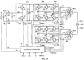
Предпочтительно, чтобы мотор-генератор включал в себя первый мотор генератор, имеющий первую многофазную обмотку и первую нейтральную точку первой многофазной обмотки, и второй мотор-генератор, имеющий вторую многофазную обмотку и вторую нейтральную точку второй многофазной обмотки. Блок ввода-вывода электроэнергии включает в себя первое соединение, соединенное с первой нейтральной точкой, и второе соединение, соединенное со второй нейтральной точкой. Гибридное транспортное средство дополнительно включает в себя первый инвертор для подвода электроэнергии, принимаемой от блока аккумулирования энергии, к первому мотор-генератору, второй инвертор для подвода электроэнергии, принимаемой от блока аккумулирования энергии, ко второму мотор-генератору, и блок управления инверторами, управляющим первым и вторым инверторами. Кроме того, блок управления инверторами может управлять первым и вторым инверторами для преобразования энергии переменного тока, подаваемой от блока ввода-вывода электроэнергии к первой и второй нейтральным точкам, в энергию постоянного тока, и для подачи энергии постоянного тока к блоку аккумулирования энергии, и/или может управлять первым и вторым инверторами для преобразования энергии постоянного тока, подаваемой от блока аккумулирования энергии к первому и второму инверторам, в энергию переменного тока, и подавать энергию переменного тока в блок ввода-вывода электроэнергии.Preferably, the motor generator includes a first motor generator having a first multiphase winding and a first neutral point of the first multiphase winding, and a second motor generator having a second multiphase winding and a second neutral point of the second multiphase winding. The power input / output unit includes a first connection connected to a first neutral point, and a second connection connected to a second neutral point. The hybrid vehicle further includes a first inverter for supplying electric power received from the power storage unit to the first motor generator, a second inverter for supplying electric power received from the power storage unit to the second motor generator, and an inverter control unit controlling the first and second inverters. In addition, the inverter control unit can control the first and second inverters to convert the AC power supplied from the electric input / output unit to the first and second neutral points to direct current energy, and to supply direct current energy to the power storage unit, and / or can control the first and second inverters to convert DC energy supplied from the energy storage unit to the first and second inverters into AC energy, and supply AC energy oh current in the input-output unit of electricity.
Предпочтительно, чтобы мотор-генератор включал в себя первый мотор генератор, имеющий первую многофазную обмотку и первую нейтральную точку первой многофазной обмотки, и второй мотор-генератор, имеющий вторую многофазную обмотку и вторую нейтральную точку второй многофазной обмотки. Блок ввода-вывода электроэнергии включает в себя первое соединение, соединенное с первой нейтральной точкой, и второе соединение, соединенное со второй нейтральной точкой. Гибридное транспортное средство дополнительно включает в себя первый инвертор, для подвода электроэнергии, принимаемой от блока аккумулирования энергии, к первому мотор-генератору, второй инвертор для подвода электроэнергии, принимаемой от блока аккумулирования энергии, ко второму мотор-генератору, и блок управления инверторами, управляющий первым и вторым инверторами. Блок управления инверторами управляет первым и вторым инверторами для преобразования энергии переменного тока, подаваемой извне посредством блока ввода-вывода электроэнергии к первой и второй нейтральным точкам, в энергию постоянного тока, и подвода энергии постоянного тока к блоку аккумулирования энергии.Preferably, the motor generator includes a first motor generator having a first multiphase winding and a first neutral point of the first multiphase winding, and a second motor generator having a second multiphase winding and a second neutral point of the second multiphase winding. The power input / output unit includes a first connection connected to a first neutral point, and a second connection connected to a second neutral point. The hybrid vehicle further includes a first inverter for supplying electric power received from the power storage unit to the first motor generator, a second inverter for supplying electric power received from the power storage unit to the second motor generator, and an inverter control unit controlling first and second inverters. The inverter control unit controls the first and second inverters to convert the AC power supplied externally by the power input / output unit to the first and second neutral points to direct current energy, and to supply the DC power to the power storage unit.
Транспортное средство согласно данному изобретению включает в себя первый приводной блок, приводимый в действие первым источником энергии; первый блок хранения для хранения первого источника энергии; первый блок приема энергии, разъемно соединенный с первым блоком подачи энергии, для приема первого источника энергии; первый соединительный блок, соединенный с первым блоком приема энергии и направляющий первый источник энергии, подаваемый к первому блоку приема энергии, к первому блоку аккумулирования; первую камеру размещения, для размещения первого блока приема энергии; первый закрывающий элемент для открытия и закрытия отверстия первой камеры размещения; второй приводной блок, приводимый в действие вторым источником энергии, отличным от первого источника энергии; второй блок для хранения второго источника энергии; второй блок приема энергии, разъемно соединенный со вторым блоком подачи энергии, для приема второго источника энергии; второй соединительный блок, соединенный со вторым блоком приема энергии и направляющий второй источник энергии, подаваемой ко второму блоку приема энергии, ко второму блоку аккумулирования; вторую камеру размещения для размещения второго блока приема энергии и независимую от первой камеры размещения; и второй закрывающий элемент для открытия и закрытия отверстия второй камеры размещения. Первый и второй блоки приема энергии располагаются на одной боковой поверхности транспортного средства. Предпочтительно, чтобы транспортное средство дополнительно включало в себя отсек для размещения пассажиров для размещения пассажиров; входное отверстие, образованное в транспортном средстве и связанное с отсеком для размещения пассажиров. Это входное отверстие располагается между первым и вторым блоками приема энергии.A vehicle according to this invention includes a first drive unit driven by a first energy source; a first storage unit for storing a first energy source; a first power receiving unit detachably connected to the first power supply unit for receiving a first energy source; a first connecting unit connected to the first power receiving unit and directing the first energy source supplied to the first power receiving unit to the first storage unit; a first placement chamber for accommodating a first power receiving unit; a first closing element for opening and closing the opening of the first placement chamber; a second drive unit driven by a second energy source different from the first energy source; a second unit for storing a second energy source; a second power receiving unit detachably connected to the second power supply unit for receiving a second energy source; a second connecting unit connected to the second power receiving unit and directing the second energy source supplied to the second power receiving unit to the second storage unit; a second placement chamber for accommodating a second power receiving unit and independent of the first placement chamber; and a second closing element for opening and closing the opening of the second placement chamber. The first and second power receiving units are located on one side surface of the vehicle. Preferably, the vehicle further includes a passenger compartment for accommodating passengers; an inlet formed in the vehicle and connected to the passenger compartment. This inlet is located between the first and second power receiving units.
Предпочтительно, чтобы первым источником энергии являлся водород или топливо, содержащее атомы водорода, первым приводным блоком являлся электрогенератор для генерирования электроэнергии, вторым источником энергии являлась электроэнергия и вторым приводным блоком являлся мотор-генератор, приводимый в действие электроэнергией.Preferably, the first energy source is hydrogen or a fuel containing hydrogen atoms, the first drive unit is an electric generator for generating electricity, the second source of energy is electricity and the second drive unit is a motor generator driven by electricity.
В другом аспекте, транспортное средство согласно данному изобретению включает в себя первый приводной блок, приводимый в действие первым источником энергии; первый блок аккумулирования для хранения первого источника энергии; первый блок приема энергии, соединенный разъемно с первым блоком подачи энергии и снабженный первым источником энергии; первый соединительный блок, соединенный с первым блоком приема энергии, и направляющий первый источник энергии, подаваемый к первому блоку приема энергии, к первому блоку аккумулирования; второй приводной блок, приводимый в действие вторым источником энергии, отличным от первого источника энергии; второй блок аккумулирования для аккумулирования второго источника энергии; второй блок приема энергии, соединенный разъемно со вторым блоком подачи энергии и снабжаемый вторым источником энергии; и второй соединительный блок, соединенный со вторым блоком приема энергии и направляющий второй источник энергии, подаваемый ко второму блоку приема энергии, ко второму блоку аккумулирования. Вышеописанное транспортное средство снабжено отсеком для размещения пассажиров, входным проемом, соединяющим отсек для размещения пассажиров с внешней частью транспортного средства. Этот входной проем расположен между первым и вторым блоками приема энергии.In another aspect, a vehicle according to this invention includes a first drive unit driven by a first energy source; a first storage unit for storing a first energy source; a first power receiving unit connected detachably to a first power supply unit and provided with a first energy source; a first connecting unit connected to the first power receiving unit and directing a first energy source supplied to the first power receiving unit to the first storage unit; a second drive unit driven by a second energy source different from the first energy source; a second storage unit for storing a second energy source; a second power receiving unit connected detachably to the second power supply unit and provided with a second energy source; and a second connecting unit connected to the second power receiving unit and directing the second energy source supplied to the second power receiving unit to the second storage unit. The vehicle described above is equipped with a compartment for accommodating passengers, an inlet opening connecting the compartment for accommodating passengers with the exterior of the vehicle. This input opening is located between the first and second power receiving units.
Согласно гибридному транспортному средству данного изобретения, в силу того, что заправочный блок и зарядный блок/блок подачи энергии располагаются на одной боковой поверхности транспортного средства, водитель не может перепутать расположение заправочного блока и зарядного блока/блока подачи энергии, и может быть исключен рост нагрузки на водителя на этапе, предшествующем процессу зарядки/заправки.According to the hybrid vehicle of the present invention, since the refueling unit and the charging unit / power supply unit are located on one side surface of the vehicle, the driver cannot confuse the location of the refueling unit and the charging unit / power supply unit, and load growth can be eliminated. on the driver at the stage preceding the charging / refueling process.
Краткое описание чертежейBrief Description of the Drawings
В дальнейшем изобретение поясняется описанием предпочтительного варианта воплощения со ссылками на сопровождающие чертежи, на которых:The invention is further explained in the description of the preferred embodiment with reference to the accompanying drawings, in which:
Фиг. 1 изображает общий вид гибридного транспортного средства, согласно варианту осуществления изобретения;FIG. 1 is a perspective view of a hybrid vehicle according to an embodiment of the invention;
Фиг. 2 - схему принципиальной конструкции, показанной на Фиг. 1, согласно изобретению;FIG. 2 is a schematic diagram of the construction shown in FIG. 1, according to the invention;
Фиг. 3 - общий вид конструкции кузова основного блока гибридного транспортного средства, согласно изобретению;FIG. 3 is a general view of a body structure of a main unit of a hybrid vehicle according to the invention;
Фиг. 4 - вид сбоку гибридного транспортного средства, согласно изобретению;FIG. 4 is a side view of a hybrid vehicle according to the invention;
Фиг. 5 - вид сбоку первой модификации гибридного транспортного средства, согласно варианту осуществления транспортного средства;FIG. 5 is a side view of a first modification of a hybrid vehicle according to an embodiment of the vehicle;
Фиг. 6 - вид сбоку второй модификации гибридного транспортного средства, согласно варианту осуществления транспортного средства;FIG. 6 is a side view of a second modification of a hybrid vehicle, according to an embodiment of the vehicle;
Фиг. 7 - вид сбоку, изображающий третью модификацию гибридного транспортного средства, согласно варианту осуществления транспортного средства;FIG. 7 is a side view showing a third modification of a hybrid vehicle according to an embodiment of the vehicle;
Фиг. 8 - схему варианта, в котором зарядный блок/блок подачи энергии и заправочный блок располагаются на одной боковой поверхности со стороны места водителя, согласно изобретению;FIG. 8 is a diagram of an embodiment in which a charging unit / power supply unit and a refueling unit are located on one side surface from a driver’s seat side according to the invention;
Фиг. 9 - вид сбоку, изображающий четвертую модификацию гибридного транспортного средства, согласно варианту осуществления транспортного средства;FIG. 9 is a side view showing a fourth modification of a hybrid vehicle according to an embodiment of the vehicle;
Фиг. 10 - вид сбоку, изображающий пятую модификацию гибридного транспортного средства, согласно варианту осуществления транспортного средства;FIG. 10 is a side view showing a fifth modification of a hybrid vehicle according to an embodiment of the vehicle;
Фиг. 11 - вид сбоку шестой модификации гибридного транспортного средства, согласно варианту осуществления транспортного средства;FIG. 11 is a side view of a sixth modification of a hybrid vehicle according to an embodiment of the vehicle;
Фиг. 12 - электрическую схему гибридного транспортного средства, согласно варианту осуществления данного изобретения, и схему подачи внешней энергии;FIG. 12 is a circuit diagram of a hybrid vehicle according to an embodiment of the present invention, and an external energy supply circuit;
Фиг. 13 - электрическую схему гибридного транспортного средства согласно варианту осуществления данного изобретения, и схему зарядки батареи;FIG. 13 is a circuit diagram of a hybrid vehicle according to an embodiment of the present invention, and a battery charging circuit;
Фиг. 14 - общий вид части кузова, оборудованного рамой, согласно изобретению;FIG. 14 is a perspective view of a part of a body equipped with a frame according to the invention;
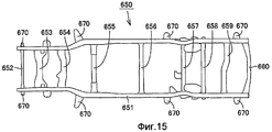
Фиг. 15 - вид сверху, изображающий раму кузова, оборудованного рамой, показанной на Фиг. 14, согласно изобретению;FIG. 15 is a plan view showing a frame of a body equipped with a frame shown in FIG. 14, according to the invention;
Фиг. 16 - схему конструкции, в которой изобретение применяется к транспортному средству на топливных элементах, согласно изобретению;FIG. 16 is a structural diagram in which the invention is applied to a fuel cell vehicle according to the invention;
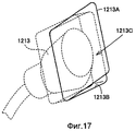
Фиг. 17 - общий вид конструкции соединительного блока и транспортного средства вблизи него, согласно изобретению;FIG. 17 is a general view of the structure of the junction block and the vehicle close to it, according to the invention;
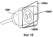
Фиг. 18 - общий вид конструкции соединительного блока и транспортного средства вблизи него, согласно изобретению.FIG. 18 is a general view of the structure of the junction block and the vehicle near it, according to the invention.
Описание предпочтительных вариантов осуществления изобретенияDescription of preferred embodiments of the invention
Варианты осуществления данного изобретения будут описаны со ссылкой на чертежи. В описании, одинаковые элементы обозначены одинаковыми ссылочными позициями.Embodiments of the present invention will be described with reference to the drawings. In the description, like elements are denoted by like reference numerals.
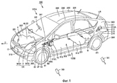
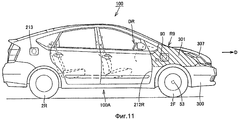
Ниже со ссылками на фиг. 1-13 описано гибридное транспортное средство 100 согласно варианту осуществления изобретения. На Фиг. 1 показан общий вид принципиальной конструкции гибридного транспортного средства 100, согласно варианту осуществления изобретения. На Фиг. 2 показана схема, изображающая принципиальную конструкцию. На Фиг. 3 показан общий вид, изображающий принципиальную конструкцию кузова 500 основного блока 200 транспортного средства гибридного транспортного средства 100.Below with reference to FIG. 1-13, a
Гибридное транспортное средство 100 включает в себя основной блок 200 транспортного средства, образованный кузовом и внешними частями, пару 2F передних колес, расположенных в передней части, по направлению движения D гибридного транспортного средства 100, и задние колеса 2R, расположенные в задней части по направлению движения D.The
Основной блок 200 транспортного средства включает в себя моторный отсек ER, расположенный спереди, по направлению движения D, гибридного транспортного средства 100, отсек CR размещения пассажиров рядом с задней частью, по направлению движения D, моторного отсека ER, и багажный отсек LR рядом с задней частью, по направлению движения D, отсека для размещения CR пассажиров.The
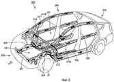
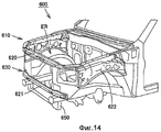
Например, как показано на Фиг. 3, унифицированный кузов используется в качестве кузова 500 основного блока 200 транспортного средства. Кузов 500 содержит переднюю стенку 550, расположенную в передней части, по направлению движения D, и определяющую размеры моторного отсека ER, стенку 560 отсека, определяющую размеры отсека CR для размещения пассажиров, и заднюю стенку 570 расположенную в задней части, по направлению движения D, основного блока 200 транспортного средства.For example, as shown in FIG. 3, the unified body is used as the
Передняя стенка 550 включает в себя переднюю поперечину 501, которая располагается на передней части основного блока 200 транспортного средства и продолжается в поперечном направлении основного блока 200 транспортного средства, передние боковые стенки 504, которые продолжаются к противоположным концам передней поперечины 501 соответственно, и определяют размеры участков боковых поверхностей моторного отсека ER, и переднюю перемычку 510, расположенную между моторным отсеком ER и отсеком размещения CR пассажиров.The
Каждая передняя боковая стенка 504 имеет вертикальный размер, который увеличивается при перемещении от передней поперечины 501 к передней перемычке 510. Передняя боковая стенка 504 имеет продольный средний участок, который изгибается для размещения переднего колеса 2F.Each
Передняя боковая стенка 504 имеет утолщение, которое увеличивается при перемещении от передней поперечины 501 к передней перемычке 510.The
Стенка 560 отсека включает в себя передние опоры 503, которые располагаются на боковых участках, находящихся на поперечных противоположных концах передней перемычки 510, соответственно, и продолжаются в горизонтальном направлении основного блока 200 транспортного средства, передние стойки 507 соединенные с верхними концами передних опор 503 соответственно, и нижние опоры 505 соединенные с нижними концами передних опор 503 соответственно.The
Кузов 500 оборудован на боковых поверхностях проемами 212L и 212R, которые продолжаются до отсека CR для размещения пассажиров для входа пассажиров. Каждый из проемов 212L и 212R имеет периферию, размеры которой заданы передней опорой 503, нижней опорой 505, передней стойкой 507 и кромкой задней стенки 570.The
В кузове 500, участок, расположенный спереди, по направлению движения D, относительно отсека CR для размещения пассажиров, имеет меньшую толщину, чем участок, расположенный сзади по направлению движения D. Таким образом, когда возникает лобовое столкновение, передняя часть кузова 500 деформируется для поглощения удара для защиты внутреннего пространства отсека CR для размещения пассажиров.In the
Множество внешних частей устанавливаются на поверхности кузова 500, имеющего вышеописанную конструкцию. Благодаря чему образуется основной блок 200 транспортного средства.Many external parts are mounted on the surface of the
Внешние части включают в себя, например, переднюю фронтальную поверхность 310, расположенную на передней части основного блока 200 транспортного средства, изображенного на Фиг. 1, передний бампер 300, расположенный ниже фронтальной поверхности 310, и передние крылья 301, закрывающие передние боковые стенки 504, изображенные на Фиг. 3, а также передние и задние двери 312 и 313 для закрытия проемов 212L и 212R.The outer parts include, for example, a front
Внешние части также включают капот 307, образующий верхнюю крышку для моторного отсека ER, задние крылья 303, расположенные сзади по направлению движения D, относительно задних дверей 313 соответственно, и задний бампер 304, расположенный ниже задних крыльев 303.The outer parts also include a
В отсеке CR для размещения пассажиров находится место DR водителя для управления гибридным транспортным средством 100, соседнее место пассажира, в поперечном направлении гибридного транспортного средства 100, к месту водителя, и задние места за местом пассажира и местом DR водителя. В примере, изображенном на Фиг. 1, место DR водителя смещено в сторону правой боковой поверхности (одной из боковых поверхностей) 100А гибридного транспортного средства 100 относительно средней линии O гибридного транспортного средства 100, продолжающейся в направлении движения D.In the passenger compartment CR, there is a driver’s seat DR for driving the
Как показано на Фиг. 1, топливный бак 201 для хранения жидкого топлива, такого как бензин, располагается ниже задних мест отсека CR для размещения пассажиров. Батарея (блок аккумулирования энергии) B, такая как топливный элемент или конденсатор большой емкости, располагается сзади по направлению движения D, относительно задних мест.As shown in FIG. 1, a
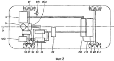
Моторный отсек ER вмещает двигатель 4 двигателя внутреннего сгорания, который генерирует движущую энергию, приводящую в действие передние колеса 2F, а также коробку TR передач.The engine compartment ER accommodates an
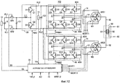
Коробка TR передач включат в себя мотор-генераторы MG1 и MG2, приводящие в движение передние колеса 2F, повышающий преобразователь 20, который усиливает электроэнергию, подаваемую от батареи В, инверторы 30 и 40, которые преобразуют энергию постоянного тока, подаваемую от повышающего преобразователя 20, в энергию переменного тока, и подают ее в мотор-генераторы MG1 и MG2 соответственно, и механизм 3 распределения энергии, образованный планетарной зубчатой передачей и тому подобным.The gearbox TR will include motor generators MG1 and MG2 driving the
Двигатель 4 смещен в сторону боковой поверхности 100A относительно средней линии O, и коробка TR передач смещена в сторону боковой поверхности 100B относительно средней линии O. Центр тяжести совместно двигателя 4 и коробки TR передач находится на или вблизи средней линии O для сохранения поперечного баланса гибридного транспортного средства 100.The
Более того, центр тяжести и батареи В и топливного бака 201 находится на или вблизи средней линии O.Moreover, the center of gravity of both battery B and
Зарядный блок/блок 90 подачи энергии (т.е. блок ввода-вывода электроэнергии), который является блоком для электрозарядки и подачи электроэнергии, а также блок 213 заправки располагаются у боковой поверхности гибридного транспортного средства 100, конкретнее у боковой поверхности 100В, противоположной боковой поверхности 100А рядом с местом DR водителя. Рулевое колесо, вал рулевого механизма, рулевой механизм и тому подобное для управления передними колесами 2F располагаются на или вблизи места DR водителя.A charging unit / power supply unit 90 (i.e., an electric input / output unit), which is an electric charge and power supply unit, as well as a
Зарядный блок/блок 90 подачи энергии и блок 213 заправки сохраняют баланс веса относительно места DR водителя.The charging unit /
В примере, изображенном на Фиг. 1, зарядный блок/блок 90 питания включает в себя соединительный блок 91, который расположен на кузове 500 и имеет отверстие для установки соединителя 190, открываемую крышку 90A, которая может закрывать отверстие соединительного блока 91, и соединение 92, соединенное с соединительным блоком 91. Соединитель 190 включает в себя зарядный соединитель, соединитель питания электроэнергией или зарядный соединитель/соединитель питания электроэнергией.In the example shown in FIG. 1, the charging unit /
Зарядный соединитель является соединителем для зарядки батареи В электроэнергией, подаваемой от промышленного электроснабжения (например, однофазный переменный ток в 100 В в Японии). Данный зарядный соединитель является, например, разъемом, подсоединяемым к основной домашней системе энергоснабжения.The charging connector is a connector for charging battery B with electricity supplied from industrial power supply (for example, a single-phase alternating current of 100 V in Japan). This charging connector is, for example, a connector connected to the main home power supply system.
Соединитель питания электроэнергией является соединителем для подвода электроэнергии (например, однофазный переменный ток в 100 В в Японии), подаваемой от гибридного транспортного средства 100 к внешней нагрузке. Более того, зарядный соединитель/соединитель питания электроэнергией является соединителем, имеющим обе функции, как зарядного соединителя, так и соединителя питания электроэнергией описанных выше, и может заряжать батарею энергией подаваемой от промышленного электроснабжения и может также подавать энергию от гибридного транспортного средства 100 на внешнюю нагрузку.The electric power supply connector is a connector for supplying electric power (for example, a single-phase alternating current of 100 V in Japan) supplied from the
Способ подачи и получения электроэнергии между соединителем 190 и зарядным блоком/блоком 90 подачи энергии может быть контактного типа, в котором часть соединителя 190 может непосредственно контактировать, по меньшей мере, с частью зарядного блока/блока 90 подачи энергии. Также, он может быть индуктивного типа.The method for supplying and receiving electric power between the
Соединение 92 соединяется с нейтральной точкой между мотор-генераторами MG1 и MG2, и энергия, подаваемая от соединителя 190, может подаваться к батарее В посредством мотор-генераторов MG1 и MG2, инверторов 30 и 40 и повышающего преобразователя 20.The
Также, зарядный блок/блок 90 подачи энергии может подавать за пределы транспортного средства энергию, сохраняемую в батарее, от соединителя 190 посредством повышающего преобразователя 20 и инверторов 30 и 40.Also, the charging unit /
В примере, изображенном на Фиг. 1, блок 213 заправки включает в себя приемник сопла 215, который образован в кузове 500 и имеет отверстие, заправочный трубопровод 214, соединенный с приемником сопла 215 и топливным баком 201, и открываемую крышку 213A, которая располагается на внешней части для закрытия отверстия приемника сопла 215.In the example shown in FIG. 1, the
Приемник сопла 215 может принимать насадку заправочного соединителя 191, расположенного за пределами гибридного транспортного средства 100. Подаваемое топливо, такое как бензин, протекает через заправочный трубопровод 214 в топливный бак 201.A
Поскольку блок 213 заправки и зарядный блок/блок 90 подачи энергии располагаются на одной боковой поверхности 100В гибридного транспортного средства 100 как описано выше, водитель может запомнить без труда положение зарядного блока/блока 90 подачи энергии и блока 213 заправки. Поэтому, когда водитель направляет гибридное транспортное средство к зарядному/заправочному стенду или к чему-либо в этом роде, вероятность ошибки связанная со способом въезда и остановки гибридного транспортного средства 100 может быть снижена.Since the
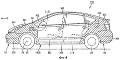
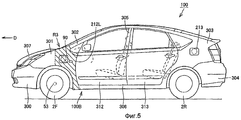
На Фиг. 4 показан вид сбоку гибридного транспортного средства 100, где зарядный блок/блок 90 подачи энергии может располагаться в любом месте на боковой поверхности 100В гибридного транспортного средства 100. Например, он может располагаться в любом месте у боковой поверхности заднего бампера 304, заднего крыла 303, задней двери 313, передней двери 312, переднего крыла 301, боковой поверхности переднего бампера 300, средней стойки 305, передней стойки 302 или нижней стойки 306. Аналогичным образом, блок 213 заправки может располагаться в любом месте боковой поверхности 100В.In FIG. 4 shows a side view of a
Зарядный блок/блок 90 подачи энергии может располагаться в области R1 боковой поверхности 100B, которая расположена спереди по направлению движения D, относительно отверстия 212L, или в области R2, которая расположена сзади по направлению движения D, относительно проема 212L. Блок 213 заправки может располагаться в области R1 или R2 на расстоянии от зарядного блока/блока 90 подачи энергии, при этом проем 212L расположен между ними.The charging unit /
Таким образом, проем 212L располагается между зарядным блоком/блоком 90 подачи энергии и блоком 213 заправки так, что зарядный блок/блок 90 подачи энергии и заправочный блок расположены на расстоянии друг от друга по направлению движения D. Вследствие этого, возможно исключить путаницу для водителя между зарядным блоком/блоком 90 подачи энергии и блоком 213 заправки.Thus, the
В силу того, что зарядный блок/блок 90 подачи энергии располагается на расстоянии от блока 213 заправки, отверстие, которое образовано в кузове 500 для установки туда соединительного блока 91 зарядного блока/блока 90 подачи энергии, может располагаться на расстоянии от отверстия, в которое устанавливается приемник сопла 215 блока 213 заправки, и возможно избежать образования участка, локально имеющего низкую жесткость в кузове 500.Due to the fact that the charging unit /
По этой причине в кузове 500 возможно избежать образования участка, который подвержен ухудшению со временем. Область R1 включает боковые поверхности переднего крыла 301 и переднего бампера 300, и область R2 включает боковые поверхности заднего крыла 303 и заднего бампера 304.For this reason, in the body of the 500 it is possible to avoid the formation of a section that is subject to deterioration over time. The region R1 includes the side surfaces of the
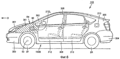
Приемник 215 сопла блока 213 заправки принимает сопло заправочного соединителя 191, который вставляется в приемник и удерживает заправочный соединитель 191 в приемнике сопла. Заправочный соединитель 191 в общем имеет регулировочный механизм для регулировки скорости или степени заправки топливом, и тяжелее, чем соединитель 190.The
Блок 213 заправки, поддерживающий тяжелый заправочный соединитель 191 как описано выше имеет более высокую жесткость, чем соединительный блок 91. Конкретнее, блок 213 заправки поддерживает заправочный трубопровод 214, и поэтому должен иметь большую жесткость, чем соединительный блок 91 соединенный с соединением 92.The
Соответственно, соединительный блок 91 меньшей жесткости расположен в области R1, и данная конструкция может исключить чрезмерное увеличение жесткости передней части кузова 500 и обеспечивает функцию поглощения удара кузовом 500. Таким образом, толщина кузова, расположенного вокруг зарядного блока/блока 90 подачи энергии, меньше, чем толщина участка кузова 500 вокруг блока 213 заправки.Accordingly, the
Более того, в общем и широко известно, что блок 213 заправки располагается у боковой поверхности 100В, а конкретнее сзади от проема 212L. Путем расположения блока 213 заправки сзади от проема 212L возможно исключить ошибку водителя.Moreover, it is generally and widely known that the
Как показано на Фиг. 1, топливный бак 201 располагается ниже задних мест и блок 213 заправки располагается в области R2 так, что длина заправочного трубопровода 214 может быть уменьшена.As shown in FIG. 1, the
Более того, как показано на Фиг. 1, мотор-генераторы MG1 и MG2 располагаются в моторном отсеке ER и зарядный блок/блок 90 подачи энергии располагается в области R1 (Фиг. 4) так, что длина соединения 92 может быть уменьшена.Moreover, as shown in FIG. 1, motor generators MG1 and MG2 are located in the engine compartment ER and the charging unit /
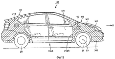
Предпочтительно, чтобы, как показано на Фиг. 5, зарядный блок/блок 90 подачи энергии располагался в области R3, которая находится у боковой поверхности 100В и, конкретнее, располагается сзади, по направлению движения D, относительно вала 53, соединенного с передними колесами 2F, и располагается спереди по направлению движения D, относительно кромки проема 212L. В кузове 500 (Фиг. 3) передняя боковая стенка 504, содержащая область R3, имеет жесткость, которая увеличивается при перемещении назад, по направлению движения D, и, вследствие этого, имеет жесткость, которая позволяет значительно оптимизировать поддержку соединительного блока 91 зарядного блока/блока 90 подачи энергии. Поэтому, даже когда процессы зарядки и внешнего питания энергией повторяются, ухудшение передней боковой стенки может быть исключено в течение длительного срока.Preferably, as shown in FIG. 5, the charging unit /
Предпочтительно, чтобы (Фиг.6) зарядный блок/блок 90 подачи энергии располагался в области R4, которая находится у боковой поверхности 100В, и конкретнее между кромкой проема 212L и передней кромкой (при рассмотрении по направлению движения D) боковой поверхности 100В, и более конкретно, располагается над верхней частью переднего колеса 2F.It is preferable that (Fig. 6) the charging unit /
Следовательно, зарядный блок/блок 90 подачи энергии может быть расположен в положении, обеспечивающем легкую установку соединителя 190 (Фиг.1), и процессы зарядки и внешнего питания энергией могут проводится эффективно.Therefore, the charging unit /
Предпочтительно, чтобы, как показано на Фиг. 7, зарядный блок/блок 90 подачи энергии располагался в области R5, которая находится у боковой поверхности 100В, и конкретнее, располагался спереди, по направлению движения D, относительно вала 53. Расположением зарядного блока/блока 90 подачи энергии в вышеуказанном положении возможно исключить контакт между соединением соединителя 190 и открытой передней дверью 312 на этапе, когда зарядный блок/блок 90 подачи энергии установлен в соединитель 190 (Фиг. 1).Preferably, as shown in FIG. 7, the charging unit /
На Фиг. 8 показана схема, в которой зарядный блок/блок 90 подачи энергии и блок 213 заправки располагаются у одной боковой поверхности 100А со стороны места DR водителя. На Фиг. 9 показан вид сбоку, в котором зарядный блок/блок питания 90 и блок 213 заправки располагаются у одной боковой поверхности 100А со стороны места DR водителя.In FIG. 8 is a diagram in which the charging unit /
Как показано на Фиг. 9, и зарядный блок/блок 90 подачи энергии и блок 213 заправки располагаются у боковой поверхности 100А и находятся близко к месту DR водителя. Вследствие этого, водитель, который покидает место DR водителя для выполнения процесса зарядки/питания энергией, может незамедлительно начать процесс заправки, зарядки.As shown in FIG. 9, and the charging unit /
Зарядный блок/блок 90 подачи энергии и блок 213 заправки могут располагаться в любом месте боковой поверхности 100А.The charging unit /
В примере на Фиг. 9, зарядный блок/блок 90 подачи энергии располагается у боковой поверхности 100A и конкретнее в области R6, которая находится спереди, по направлению движения D, относительно кромки проема 212R со стороны места DR водителя. Блок 213 заправки располагается у боковой поверхности 100A и конкретнее в области R7, которая находится сзади по направлению движения, относительно кромки проема 212R.In the example of FIG. 9, the charging unit /
Как было описано выше, проем 212R располагается между зарядным блоком/блоком 90 подачи энергии и блоком 213 заправки так, что путаница, связанная с зарядным блоком/блоком 90 подачи энергии и блоком 213 заправки может быть исключена, и кузов 500 может сохранить функцию поглощения удара.As described above, an opening 212R is located between the charging unit /
В примере на Фиг. 10, зарядный блок/блок 90 подачи энергии располагается у боковой поверхности 100А и конкретнее в области R8, которая находится сзади по направлению движения D относительно вала 53, и спереди по направлению движения D, относительно кромки проема 212R.In the example of FIG. 10, the charging unit /
Аналогичным образом, в примере на Фиг. 5 можно исключить ухудшение передней боковой стенки 504 в течение длительного времени, даже когда процесс зарядки и внешнее питание энергией повторяются.Similarly, in the example of FIG. 5, deterioration of the
В примере на Фиг. 11 зарядный блок/блок 90 подачи энергии располагается у боковой поверхности 100A и конкретнее в области R9, которая находится спереди по направлению движения D, относительно кромки проема 212R над передними колесами 2F.In the example of FIG. 11, the charging unit /
Аналогичным образом, в примере на Фиг. 6 можно облегчить процесс зарядки и внешнего питания энергией и процесс заправки.Similarly, in the example of FIG. 6, the charging process and external power supply and the charging process can be facilitated.
На Фиг. 12 показана структурная схема гибридного транспортного средства 100 в соответствии с вариантом осуществления данного изобретения. Ниже описан способ зарядки батареи В энергией переменного тока, подаваемой от соединителя 190.In FIG. 12 is a block diagram of a
Положительный электрод батареи B соединяется с положительной линией PL1, и отрицательный электрод таковой соединяется с отрицательной линией NL1. Конденсатор C1 подключен между положительной линией PL1 и отрицательной линией NL1. Повышающий преобразователь 20 подключен между положительной линией PL1 и отрицательной линией NL1 с одной стороны, и положительной линией PL2 и отрицательной линией NL2 с другой стороны. Конденсатор C2 подключен между положительной линией PL2 и отрицательной линией NL2. Инвертор 30 подключен между мотор-генератором MG1 и положительной линией PL2 и отрицательной линией NL2. Инвертор 40 подключен между мотор-генератором MG2 и положительной линией PL2 и отрицательной линией NL2.The positive electrode of the battery B is connected to the positive line PL1, and the negative electrode thereof is connected to the negative line NL1. Capacitor C1 is connected between the positive line PL1 and the negative line NL1.
Мотор-генератор MG1 включает в себя в качестве статорной катушки трехфазную катушку 11, и мотор-генератор MG2 включает в себя качестве статорной катушки трехфазную катушку 12.The motor generator MG1 includes a three-
Повышающий преобразователь 20 включает в себя электрический реактор L1, транзисторы Q1, Q2 n-p-n типа, и диоды D1, D2. Один конец реактора L1 соединен с положительной линией PL1, и другой конец соединен со средней точкой между транзистором Q1 n-p-n типа и транзистором Q2 n-p-n типа, т.е. с точкой между эмиттером транзистора Q1 n-p-n типа и коллектором транзистора Q2 n-p-n типа. Транзисторы Q1 и Q2 n-p-n типа подключены последовательно между положительной линией PL1 и отрицательными линиями NL1 и NL2. Коллектор транзистора Q1 n-p-n типа соединен с положительной линией PL2 инверторов 30, 40, и эмиттер транзистора Q2 n-p-n типа соединен с отрицательными линиями NL1 и NL2. Диоды D1 и D2 располагаются соответственно у транзисторов Q1 и Q2 n-p-n типа соответственно, и каждый соединяется между коллектором и эмиттером соответствующего транзистора Q1 или Q2 для протекания тока со стороны эмиттера в сторону его коллектора.
Инвертор 30 образован U-, V- и W-фазными плечами 31, 32 и 33, которые подключены параллельно друг другу, между положительной и отрицательной линией PL2 и NL2.The
Плечо 31 U-фазы образовано из транзисторов Q3 и Q4 n-p-n типа, соединенных последовательно. Плечо 32 V-фазы образовано из транзисторов Q5 и Q6 n-p-n типа, соединенных последовательно. Плечо 33 W-фазы образовано из транзисторов Q7 и Q8 n-p-n типа, соединенных последовательно. Диоды D3-D8 расположены у транзисторов Q3-Q8 n-p-n типа, соответственно, и каждый подключен между коллектором и эмиттером соответствующего транзистора для протекания тока со стороны эмиттера в сторону коллектора.The
Средняя точка каждого фазного плеча инвертора 30 соединена с концом фазы каждой фазной катушки трехфазной катушки 11, включенной в мотор-генератор MG1. Таким образом, мотор-генератор MG1 является трехфазным двигателем с постоянным магнитом, и один конец каждой из трех, т.е. катушек U-, V- и W-фазы совместно, соединен с нейтральной точкой M1. Другие концы катушки U-, V- и W-фазы подсоединены к средним точкам между транзисторами Q3 и Q4 n-p-n типа, между транзисторами Q5 и Q6 n-p-n типа, и между транзисторами Q7 и Q8 n-p-n типа, соответственно.The midpoint of each phase arm of the
Инвертор 40 соединен параллельно с инвертором 30 между противоположными концами конденсатора С2. Инвертор 40 образован плечами 41, 42 и 43 U-, V- и W-фазы, которые подключены параллельно друг другу между положительной и отрицательной линией PL2 и NL2.The
Плечо 41 U-фазы образовано из транзисторов Q9 и Q10 n-p-n типа, соединенных последовательно. Плечо 22 V-фазы образовано из транзисторов Q11 и Q12 n-p-n типа, соединенных последовательно. Плечо 43 W-фазы образовано из транзисторов Q13 и Q14 n-p-n типа, соединенных последовательно. Транзисторы Q9-Q14 n-p-n типа соответствуют транзисторам Q3-Q8 n-p-n типа в инверторе 30 соответственно. Таким образом, инвертор 40 имеет ту же конфигурацию, что и инвертор 30. Диоды D9-D14 располагаются у транзисторов Q9-Q14 n-p-n типа соответственно, и каждый подключен между коллектором и эмиттером соответствующего транзистора для протекания тока со стороны эмиттера в сторону коллектора.The
Средняя точка каждого фазного плеча инвертора 40 соединяется с концом фазы фазной катушки трехфазной катушки 12, включенной в мотор-генератор MG2. Таким образом, мотор-генератор MG2 является трехфазным двигателем с постоянным магнитом, и один конец каждой из трех, т.е. катушек U-, V- и W-фазы совместно, соединен с нейтральной точкой M2. Другие концы катушки U-, V- и W-фазы подсоединены к средней точке между транзисторами Q9 и Q10n-p-n типа, между транзисторами Q11 и Q12 n-p-n типа, и между транзисторами Q13 и Q14 n-p-n типа соответственно.The midpoint of each phase arm of the
Батарея В представляет собой перезаряжаемую батарею, такую как никель-гидридная батарею или ионно-литиевую батарею. Датчик 10 напряжения определяет напряжение Vb батареи, обеспечиваемое батареей В, и передает измеренное напряжение Vb батареи в устройство 70 управления. Системные реле SR1 и SR2 включаются/выключаются по сигналу SE из устройства 70 управления. Более конкретно, системные реле SR1 и SR2 включаются по сигналу SE при уровне H (высокий логический уровень), получаемом от устройства 70 управления, и выключаются по сигналу SE при уровне L (низкий логический уровень), получаемом от устройства 70 управления. Конденсатор С1 сглаживает напряжение постоянного тока, подаваемое от батареи В, и подает сглаженное напряжение постоянного тока в повышающий преобразователь 20.Battery B is a rechargeable battery such as a nickel hydride battery or a lithium ion battery. The
Повышающий преобразователь 20 повышает напряжение постоянного тока, подаваемое с конденсатора С1, и подает его к конденсатору С2. Более конкретно, когда повышающий преобразователь 20 принимает сигнал PWC от устройства 70 управления, он повышает и подает напряжение постоянного тока к конденсатору С2 в соответствии с периодом, в течение которого сигнал PWC удерживает транзистор Q2 n-p-n типа включенным. В данном случае, сигнал PWC удерживает транзистор Q1 n-p-n типа выключенным. Согласно сигналу PWC от устройства 70 управления, повышающий преобразователь 20 понижает напряжение постоянного тока, подаваемое от инвертора 30 и/или 40 посредством конденсатора С2, и заряжает батарею B.
Конденсатор C2 сглаживает напряжение постоянного тока, подаваемое с повышающего преобразователя 20, и подает сглаженное напряжение постоянного тока в инверторы 30, 40. Датчик напряжения 13 определяет напряжение между противоположными концами конденсатора С2, т.е. выходное напряжение Vm повышающего преобразователя 20 (соответствующее входному напряжению, подаваемому к инверторам 30, 40 (это является истиной в нижеследующем описании)), и передает измеренное выходное напряжение Vm в устройство 70 управления.The capacitor C2 smoothes the DC voltage supplied from the
Когда на инвертор 30 подается напряжение постоянного тока от конденсатора C2, инвертор 30 преобразует напряжение постоянного тока в напряжение переменного тока, основываясь на сигнале PWM1 подаваемом от устройства 70 управления, и приводит в действие мотор-генератор MG1. Таким образом, мотор-генератор MG1 приводится в действие для формирования крутящего момента, задаваемого значением TR1 команды крутящего момента. Инвертор 30 преобразует напряжение переменного тока, которое вырабатывается мотор-генератором MG1 во время рекуперативного торможения гибридного транспортного средства, оборудованного устройством выведения энергии, в напряжение постоянного тока, основываясь на сигнале PWM1 подаваемом из устройства 70 управления, и подает преобразованное напряжение постоянного тока в повышающий преобразователь 20 посредством конденсатора C2. Это рекуперативное торможение включает в себя торможение, которое осуществляется, когда водитель гибридного транспортного средства манипулирует педалью тормоза, и данное торможение сопровождается генерированием рекуперативной энергии. Также, рекуперативное торможение включает в себя замедление (или остановку ускорения) транспортного средства, которое не выполняется действием педали тормоза, но выполняется отпусканием педали ускорения во время движения, когда выполняется генерирование рекуперативной энергии.When the DC voltage from the capacitor C2 is supplied to the
Инвертор 30 приводит в действие мотор-генератор MG1 согласно сигналу PWM1 от устройства 70 управления так, что напряжение VAL переменного тока для промышленного электроснабжения может выводится с контактов 61 и 62 зарядного блока/блока 90 подачи энергии.The
Когда на инвертор 40 подается напряжение постоянного тока от конденсатора C2, он преобразует напряжение постоянного тока в напряжение переменного тока, основываясь на сигнале PWM2 от устройства 70 управления для приведения в действие мотор-генератора MG2. Таким образом, мотор-генератор MG2 приводится в действие для формирования крутящего момента, задаваемого значением TR2 команды крутящего момента. Более того, когда гибридное транспортное средство, оборудованное устройством вывода движущей энергии, выполняет рекуперативное торможение, инвертор 40 преобразует напряжение переменного тока, генерируемое мотор-генератором MG2, в напряжение постоянного тока, основываясь на сигнале PWM2 от устройства 70 управления, и подает преобразованное напряжение постоянного тока в повышающий преобразователь 20 посредством конденсатора C2.When a DC voltage is supplied to the
Более того, инвертор 40 приводит в действие мотор-генератор MG2 согласно сигналу PWM2 от устройства 70 управления так, что напряжение VAС переменного тока для промышленного электроснабжения может выводится с контактов 61 и 62 зарядного блока/блока 90 подачи энергии.Moreover, the
Датчик 14 тока определяет ток двигателя MCRT1, проходящий через мотор-генератор MG1, и передает значение измеренного тока двигателя MCRT1 в устройство 70 управления. Датчик 15 тока определяет ток двигателя MCRT2, проходящий через мотор-генератор MG2, и передает значение измеренного тока двигателя MCRT2 в устройство 70 управления.The
Зарядный блок/блок 90 подачи энергии включает в себя первичную катушку 51 и вторичную катушку 52. Первичная катушка 51 подключена между нейтральной точкой M1 трехфазной катушки 11, включенной в мотор-генератор MG1 и нейтральной точкой M2 трехфазной катушки 12, включенной в мотор-генератор MG2. Зарядный блок/блок 90 подачи энергии преобразует напряжение переменного тока, образуемое между нейтральными точками M1 и M2 мотор-генераторов MG1 и MG2 в напряжение VAC переменного тока электроснабжения от сети общего пользования, и выводит напряжение переменного тока через контакты 61 и 62.The charging unit /
На Фиг. 13 показана структурная схема гибридного транспортного средства 100 в соответствии с вариантом осуществления данного изобретения. Ниже описан способ подачи переменного тока в соединитель 190 и подачи электроэнергии за пределы транспортного средства. Из шести транзисторов в каждом из инверторов 30 и 40, которые образованы трехфазными мостовыми схемами соответственно, можно получить режимы включения и выключения, в которых количество вариантов комбинаций равно восьми. В двух из этих восьми вариантов переключения межфазное напряжение равняется нулю, состояние напряжения такого рода рассматривается как вектор нулевого напряжения. В данном векторе нулевого напряжения может быть рассмотрено, что три транзистора на верхнем плече находятся в одинаковом режиме оперативных переключений (все включены или все выключены), а также может быть рассмотрено, что все три транзистора на нижнем плече, все переходят в одинаковый режим оперативных переключений. На Фиг. 13 изображено три транзистора на верхнем плече инвертора 30, как верхнее плечо 30А, а также изображено три транзистора на нижнем плече инвертора 30, как нижнее плечо 30В. Аналогично, на Фиг. 13 изображено три транзистора на верхнем плече инвертора 40, как верхнее плечо 40А, а также изображено три транзистора на нижнем плече инвертора 40, как нижнее плечо 40В.In FIG. 13 shows a block diagram of a
Как показано на Фиг. 13, данная нуль-фазовая эквивалентная схема может быть рассмотрена как однофазный PWM (ШИМ) преобразователь, входным сигналом которого является энергия однофазного переменного тока, подводимая к нейтральным точкам M1 и M2 посредством линий ACL1(92) и ACL2(92) подвода энергии соединителя 190. Соответственно с этим вектор нулевого напряжения изменяется в каждом из инверторов 30 и 40 для управления переключением так, что инверторы 30 и 40 могут работать как плечи однофазного PWM преобразователя. Таким образом, энергия переменного тока, подаваемая от линий ACL1 и ACL2 подвода энергии, может преобразовываться в энергию постоянного тока, которая подается к положительной линии PL2. Энергия постоянного тока, преобразованная таким образом, подается к повышающему преобразователю 20 посредством конденсатора С2 для зарядки батареи В.As shown in FIG. 13, this zero-phase equivalent circuit can be considered as a single-phase PWM (PWM) converter, the input signal of which is the energy of a single-phase alternating current supplied to the neutral points M1 and M2 by means of the power supply lines of the
Несмотря на то, что данный вариант осуществления изобретения описан для случая, когда он применяется к гибридному транспортному средству, имеющему составной кузов, он не является ограничивающим. На Фиг. 14 показан общий вид, изображающий часть кузова, оборудованного рамой 600, и на Фиг. 15 показан вид сверху, изображающий раму 650 кузова 600, оборудованного рамой, описанной на Фиг. 14.Although this embodiment is described for the case when it is applied to a hybrid vehicle having a composite body, it is not limiting. In FIG. 14 is a perspective view showing a part of a body equipped with a
В варианте на Фиг. 14, кузов 600, оборудованный рамой, включает в себя раму 650 и кузов 610 коробчатого типа, зафиксированный на верхней поверхности рамы 650.In the embodiment of FIG. 14, a
Кузов 610 имеет передний участок 630, задающий размеры моторного отсека ER. Передний участок 630 включает в себя участок верхней опоры 620, расположенный на передней поверхности, участок нижней опоры 621 и участки 622 передних крыльев, определяющие размеры боковых поверхностей моторного отсека ER.The
Участки верхней кромки участка 620 верхней опоры и участки 622 передних крыльев определяют размеры части отверстия моторного отсека ER, и участок 621 нижней опоры располагается под участком 620 верхней опоры.The upper edge portions of the
Центральный участок участка 620 верхней опоры, участки верхней кромки участков 622 передних крыльев и центральный участок участка 621 нижней опоры имеют уменьшенную толщину так, что реализуется гибкая конструкция уменьшенного веса. Таким образом, данная конструкция может исключить увеличение вибрации панели капота (не показана).The central portion of the
Зарядный блок/блок 90 подачи энергии располагается на участке 622 передних крыльев, имеющем гибкую конструкцию. Таким образом, обеспечение зарядным блоком/блоком 90 подачи энергии может исключить увеличение жесткости участка 622 переднего крыла и вследствие этого увеличение вибрации панели капота в большей степени, по сравнению со случаем, когда блок 213 заправки, изображенный на Фиг. 1, устанавливается на нем.The charging unit /
Как показано на Фиг. 13, рама 650 включает в себя пару боковых стенок 651, продолжающихся в направлении движения D гибридного транспортного средства 100, множество участков 652-660 боковых опор, расположенных между данными боковыми стенками 651, и множество скрепляющих 670 участков, скрепляющих кузов 610 и раму 650 вместе. В силу того, что кузов, оборудованный рамой 600, включает в себя раму 650, описанную выше, можно обеспечить высокую жесткость. Например, для процесса буксировки, кузов 650 может быть оборудован буксировочным участком так, что деформация или что-либо в этом роде кузова, оборудованного рамой 600, можно исключить.As shown in FIG. 13, the
Данный вариант осуществления изобретения описан, основываясь на так называемом "последовательно-параллельном гибриде", который является конкретным типом гибридов. Несмотря на это, он не является ограничивающим. Более конкретно, данный вариант осуществления может применяться к последовательному типу гибрида, т.е. тип гибрида, в котором транспортное средство включает в себя двигатель, который является двигателем внутреннего сгорания, требующим снабжения топливом, и ведущий двигатель (т.е. двигатель для движения), приводящий в действие колеса посредством электроэнергии, выработанной двигателем и/или электроэнергии, запасенной в батарее. Более того, данный вариант осуществления изобретения может также применяться к параллельному типу гибрида, в котором как двигатель, так и электродвигатель, могут обеспечивать движущую энергию на ведущий вал.This embodiment of the invention is described based on the so-called "serial-parallel hybrid", which is a specific type of hybrids. Despite this, it is not limiting. More specifically, this embodiment can be applied to a sequential type of hybrid, i.e. a type of hybrid in which the vehicle includes an engine, which is an internal combustion engine, requiring a fuel supply, and a driving engine (i.e., an engine for driving) driving the wheels by electric power generated by the engine and / or electric power stored in the battery. Moreover, this embodiment of the invention can also be applied to a parallel type of hybrid, in which both the motor and the electric motor can provide motive energy to the drive shaft.
В гибридном транспортном средстве согласно варианту осуществления изобретения способы использования нейтралей M1, M2 мотор-генераторов MG1 и MG2 принимаются как способ зарядки батареи В, и способ подачи электроэнергии за пределы транспортного средства. Несмотря на это, он не является ограничивающим. Например, специализированное зарядное устройство/устройство питания, которое имеет функции инвертора, и преобразователя постоянного тока в постоянный (DC/DC) может использоваться для обеспечения зарядки и подачи электроэнергии. Данное специализированное зарядное устройство/устройство питания подключается между конденсатором С1 и системными реле SR1 и SR2 на Фиг. 12.In a hybrid vehicle according to an embodiment of the invention, the methods for using the neutrals M1, M2 of the motor generators MG1 and MG2 are adopted as a method of charging the battery B, and a method of supplying electricity outside the vehicle. Despite this, it is not limiting. For example, a specialized charger / power device that has the functions of an inverter and a DC / DC converter (DC / DC) can be used to provide charging and power supply. This dedicated charger / power device is connected between capacitor C1 and system relays SR1 and SR2 in FIG. 12.
Данный вариант осуществления изобретения описан для случая, в котором изобретение применяется к гибридному транспортному средству, пример не является ограничивающим.This embodiment is described for the case in which the invention is applied to a hybrid vehicle, the example is not limiting.
Например, данное изобретение также может применяться к транспортному средству на топливных элементах.For example, the invention can also be applied to a fuel cell vehicle.
На Фиг. 16 показана конструкция, в которой изобретение применяется к транспортному средству 1000 на топливных элементах. Транспортное средство 1000 на топливных элементах включает в себя топливный элемент 1100, блок 1200 аккумулирования энергии, такой как конденсатор, инвертор 1400 для движения, инвертор 1600 для дополнительного оборудования, вспомогательный двигатель 1700 и ЭБУ (Электронный Блок Управления) 1800. Устройство управления электрической системой согласно данному варианту осуществления изобретения выполнено, например, в виде программы, выполняемой ЭБУ 1800.In FIG. 16 shows a design in which the invention is applied to a
Топливный элемент 1100 генерирует электроэнергию посредством химической реакции водорода и кислорода в воздухе. Электроэнергия, вырабатываемая топливным элементом 1100, запасается в блоке 1200 аккумулирования энергии или потребляется устройствами, установленными на транспортном средстве 1000 на топливных элементах. В силу того, что топливный элемент 1100 может использовать известные общие технологии, дополнительное описание не требуется.The
Блок 1200 аккумулирования энергии выполнен из, например, множества аккумуляторных элементов (конденсаторы с двойным электрическим слоем), соединенных последовательно, и может также быть перезаряжаемой батареей или что-либо в этом роде. Инвертор 1400 для движения преобразует электроэнергию постоянного тока, подаваемую от топливного элемента 1100 и блока 1200 аккумулирования энергии, в электроэнергию переменного тока, и приводит в действие рабочий двигатель 1500. Во время рекуперативного торможения он преобразует электроэнергию переменного тока, генерируемую рабочим двигателем 1500, в электроэнергию постоянного тока и подает ее в блок 1200 аккумулирования энергии.The
Рабочий двигатель 1500 является трехфазной динамоэлектрической машиной переменного тока. Катушки U-, V- W-фазы намотаны вокруг статора рабочего двигателя 1500. Концы на одной стороне катушек U -, V- и W-фазы совместно соединены с нейтральной точкой. Другие концы катушек U-, V- и W-фазы соединяются с рабочим инвертором 1400.The 1500 working motor is a three-phase alternating current dynamoelectric machine. U-, V-, and W-phase coils are wound around the stator of the working
Соединение 1192В соединительного блока (второй соединительный блок) 1090 соединяется с нейтральной точкой рабочего двигателя 1500. К данному соединительному блоку 1090 возможно подсоединить, например, соединитель 1190, соединенный с источником питания переменного тока таким, как основной соединитель домашней системы электроснабжения. Поэтому электроэнергия переменного тока может подаваться в рабочий двигатель 1500.The
Вспомогательный двигатель 1700 аналогичным образом является трехфазной динамоэлектрической машиной переменного тока. Катушки U-, V- и W-фазы намотаны вокруг статора вспомогательного двигателя 1700. Концы на одной стороне его катушек U-, V- и W-фазы совместно соединены с нейтральной точкой. Другие концы катушек U-, V- и W-фазы соединяются со вспомогательным инвертором 1600.The 1700 auxiliary motor is likewise a three-phase alternating current dynamoelectric machine. U-, V-, and W-phase coils are wound around the stator of the
Соединение 1192A соединительного блока 1090 соединяется с нейтральной точкой вспомогательного двигателя 1700 так, что энергия переменного тока может подаваться к нейтральной точке вспомогательного двигателя 1700 от соединительного блока 1090 от соединителя 1190 посредством соединительного блока 1090.The
Соединительный блок 1090, как описано ранее, устанавливается у одной боковой поверхности 100A транспортного средства 1000 на топливных элементах.The connecting
Как было описано выше, электроэнергия переменного тока, подаваемая к рабочему двигателю 1500 и вспомогательному двигателю 1700, преобразуется в электроэнергию постоянного тока рабочим инвертором 1400 и вспомогательным инвертором 1600, и подается в блок 1200 аккумулирования энергии для зарядки блока 1200 аккумулирования энергии.As described above, the AC power supplied to the working
Данная движущая энергия, подаваемая от ведущего двигателя 1500, приводит в движение транспортное средство 1000 на топливных элементах. Во время процесса рекуперации колеса (не показаны) приводят в действие рабочий двигатель 1500 для функционирования его в качестве генератора электроэнергии. Таким образом, ведущий двигатель 1500 работает как рекуперативный тормоз, преобразуя энергию торможения в электроэнергию.This driving energy supplied from the
Вспомогательный инвертор 1600 преобразует электроэнергию постоянного тока, подаваемую от топливного элемента 1100 и блока 1200 аккумулирования энергии, в электроэнергию переменного тока и приводит в действие вспомогательный двигатель 1700. Вспомогательный двигатель 1700 приводит в действие оборудование, работающее для эксплуатации топливного элемента 1100. Оборудование, приводимое в действие для эксплуатации топливного элемента 1100, будет описано позже.The
Вольтметр 1802 и пусковой переключатель 1804 подсоединены к ЭБУ 1800. Вольтметр определяет системное напряжение (т.е. напряжение блока аккумулирования энергии 1200) и передает сигнал, указывающий измеренный результат в ЭБУ 1800. Водитель транспортного средства 1000 на топливных элементах может управлять пусковым переключателем 1804. Когда пусковой переключатель 1804 включается, ЭБУ 1800 запускает систему транспортного средства. Когда пусковой переключатель 1804 выключается, ЭБУ 1800 останавливает систему транспортного средства.A
ЭБУ 1800 управляет устройствами и тому подобным, установленными на транспортном средстве 1000 на топливных элементах, чтобы установить транспортное средство в требуемый режим движения, основываясь на режиме движения транспортного средства, положении педали газа, измеряемого датчиком положения педали газа (не показан), величине нажатия педали тормоза, положении переключателя скоростей, напряжении блока 1200 аккумулирования энергии, состоянии управляемого пускового переключателя 1804, а также карте и программе, сохраняемыми в ПЗУ (Постоянное Запоминающее Устройство).The
Транспортное средство 1000 на топливных элементах включает в себя бак 1102 для водорода, водородный насос 1104, воздушный фильтр 1106, воздушный насос 1108, увлажнитель 1110, водяной насос 1112, разбавитель 1114.A
Бак 1102 для водорода содержит запас водорода. Сплав, хранящий водород, может использоваться вместо бака 1102 для водорода. Бак 1102 для водорода соединяется с соединительным блоком 1213, который подает в бак 1102 для водорода водород, подаваемый из соединительного блока 1191 подачи водорода.
Поскольку оба соединительных блока 1213 и 1090 располагаются на боковой поверхности 100А, может быть исключена путаница, связанная с тем, на какой боковой поверхности располагаются соединительные блоки 1213 и 1090, когда водитель выполняет процесс зарядки или процесс подачи водорода.Since both
Конкретнее, так как оба соединительных блока 1213 и 1090 располагаются на одной боковой поверхности 100А, возможно исключить ошибку, связанную со способом въезда, когда водитель направляет транспортное средство к зарядной/водородподающей станции.More specifically, since both of the connecting
Более того, разнесением соединительных блоков 1213 и 1090 друг от друга в продольном направлении транспортного средства, как показано на Фиг. 11, возможно исключить охрупчивание водородом, которое может возникнуть в и вокруг соединительного блока 1090, вызванное водородом, подаваемым из соединительного блока 1191 подачи водорода.Moreover, by spacing the connecting
Например, проем, который продолжается к отсеку для размещения пассажиров и позволяет войти пассажирам, располагается между соединительными блоками 1213 и 1090. Данная конфигурация может исключить разрушение водородом в и вокруг соединительного блока 1090, и также может исключить путаницу оператором между соединительными блоками 1213 и 1090.For example, an opening that extends to the passenger compartment and allows passengers to enter is located between the connecting
Взаимное расположение между зарядным блоком/блоком 90 подачи энергии и соединительным участком 1213 в первом варианте осуществления изобретения может применяться к соединительным блокам 1213 и 1090.The mutual arrangement between the charging unit /
На Фиг. 17 показан общий вид, изображающий конструкцию соединительного блока и транспортного средства вблизи него. Как показано на Фиг. 17, соединительный блок 1213 размещается в распределительной камере 1213С, образованной у боковой поверхности 100А транспортного средства. Распределительная камера 1213С имеет направленное наружу отверстие 1213B, которое может закрываться открываемой крышкой 1213А, размещенной с возможностью поворота на боковой поверхности 100А. Соединительный блок 1213 может принимать блок насадки соединительного блока 1191 подачи водорода. Для подачи водорода в транспортное средство оператор открывает крышку 1213А, устанавливает соединительный блок 1191 подачи водорода в соединительный блок 1213 и начинает подачу водорода. Когда подача водорода завершена, отверстие соединительного блока 1213 закрывается открываемой внутрь крышкой (не показана) и отверстие 1213В закрывается крышкой 1213А.In FIG. 17 is a perspective view showing the structure of a connecting unit and a vehicle in the vicinity thereof. As shown in FIG. 17, the connecting
Поскольку соединительный блок 1213 располагается в закрываемой распределительной камере 1213С, как описано выше, внешняя утечка водорода может быть исключена, и возможно исключить коррозию кузова транспортного средства вызванную водородом, которая может возникнуть на участке вокруг распределительной камеры 1213С.Since the connecting
На Фиг. 18 показан общий вид, изображающий конструкцию соединительного блока 1090 и транспортного средства вблизи него. Соединительный блок 1090 размещается в распределительной камере 1090С, которая не связана с распределительной камерой 1213С.In FIG. 18 is a perspective view showing the structure of a connecting
Вследствие этого, контакт соединительного блока 1090 с водородом может быть исключен, и коррозия соединительного блока 1090 может быть исключена.As a result, contact of the connecting
Конкретнее, когда отверстие 1212 находится между соединительными блоками 1090 и 1213, соответствующее расстояние сохраняется между соединительными блоками 1090 и 1213, и контакт водорода с соединительным блоком 1090 может быть исключен.More specifically, when the hole 1212 is between the connecting
Для выработки электроэнергии топливным элементом 1100 в данном варианте осуществления изобретения, водородный насос 1104 подает водород, находящийся в баке 1102 для водорода на анодную сторону топливного элемента 1100. Для остановки выработки энергии топливным элементом 1100, водородный насос 1104 приводится в действие для выполнения процесса остановки подачи оставшегося водорода с анодной стороны топливного элемента 1100. Вспомогательный двигатель 1700 приводит в действие водородный насос 1104.In order to generate electricity by the
Воздушный насос 1108 подводит воздух к катодной стороне топливного элемента 1100. Во время выработки энергии топливным элементом 1100 воздушный насос 1108 приводится в действие для подвода воздуха через воздушный фильтр 1106, и воздух увлажняется увлажнителем 1110 и затем подается к катоду топливного элемента 1100. Когда выработка энергии с помощью топливного элемента 1100 должна быть остановлена, воздушный насос 1108 приводится в действие. Таким образом, воздух, подаваемый через воздушный фильтр 1106, подается к катоду топливного элемента 1100 без увлажнения, и выполняется процесс остановки высушивания топливного элемента 1100. Воздушный насос 1108 является насосом, приводимым в движение вспомогательным двигателем 1700.An
Водяной насос 1112 выпускает охлаждающую воду для охлаждения топливного элемента 1100. Охлаждающая вода, выпускаемая водяным насосом 1112, циркулирует в топливном элементе 1100. Водяной насос 1112 является насосом, приводимым в движение вспомогательным двигателем 1700.The
Водород, проходящий через анодную сторону топливного элемента 1100, и воздух, проходящий через катодную сторону топливного элемента 1100, направляются в разбавитель 1114. Разбавитель 1114 уменьшает концентрацию водорода, и разбавленный водород выпускается из транспортного средства.Hydrogen passing through the anode side of the
Несмотря на то, что описывается только вспомогательный двигатель 1700, вспомогательные двигатели 1700 устанавливаются для соответствующих водородного насоса 1104, воздушного насоса 1108 и водяного насоса 1112 соответственно. В данном варианте осуществления изобретения вспомогательный двигатель 1700 приводится в действие преобразованием электроэнергии, подаваемой от блока 1200 аккумулирования энергии, из энергии постоянного тока в энергию переменного тока. Однако может применяться конфигурация, которая приводит в действие вспомогательный двигатель 1700 энергией постоянного тока без применения вспомогательного инвертора 1600.Although only the
Во втором варианте осуществления изобретения водород, используемый в топливном элементе 1100, подается от соединительного блока 1213. Пример не является ограничивающим.In a second embodiment of the invention, the hydrogen used in the
Например, в системе, использующей установку реформинга, которая извлекает водород из топлива, такого как метанол, содержащего атомы водорода, метанол подается в соединительный блок 1213. Соединительный блок 1213 соединяется с баком для метанола (не показан), используемым независимо от бака 1102 для водорода, и метанол хранится в баке для метанола.For example, in a system using a reformer that extracts hydrogen from a fuel, such as methanol containing hydrogen atoms, methanol is supplied to a
Водород вырабатывается посредством подачи метанола, находящегося в баке для метанола, и воды к установке реформинга и сохраняется в баке 1102 для водорода. В ином случае, может применяться конфигурация, которая подает вырабатываемый водород непосредственно к топливному элементу.Hydrogen is generated by supplying methanol in the methanol tank and water to the reforming unit and stored in the
В системе непосредственной подачи метанола, которая непосредственно подает метанол к топливному элементу, метанол аналогичным образом подается к соединительному блоку.In a direct methanol feed system that directly delivers methanol to the fuel cell, methanol is likewise supplied to the junction block.
В данной системе непосредственной подачи метанола метанол подается совместно с водой к аноду топливного элемента 1100 и распадается для образования ионов водорода, электронов и углекислого газа, используя катализатор, например платину. Ионы водорода проходят через электролитическую пленку к катоду и вступают в реакцию с кислородом в воздухе для превращения в воду. Электроны подаются как электроэнергия через контакты.In this direct methanol feed system, methanol is supplied together with water to the anode of the
В транспортном средстве 1000 на топливных элементах, в котором используется схема непосредственной подачи метанола, бак для метанола соединяется с соединительным блоком 1213, хранящим метанол, подаваемый от соединительного блока 1213. Метанол, находящийся в баке для метанола, подается к топливному элементу 1100.In a
В транспортном средстве 1000 на топливных элементах, оборудованном установкой реформинга этанола, этанол подается в соединительный блок 1213. В данном транспортном средстве 1000 на топливных элементах, оборудованном установкой реформинга этанола, установка реформинга этанола снабжается этанолом и водой для выработки водорода и углекислого газа. Образованный таким образом водород подается к топливному элементу для получения электроэнергии.In a
Транспортное средство 1000 на топливных элементах, оборудованное установкой реформинга этанола, снабжается этанолом через соединительный блок 1213, этанол сохраняется в баке для этанола. Этанол из бака для этанола подается в установку реформинга этанола.A
Как описано выше, данное изобретение может применяться к различным типам транспортных средств 1000 на топливных элементах. Несмотря на то, что третий вариант осуществления изобретения описан в связи с транспортным средством на топливных элементах, в котором блок 1200 аккумулирования энергии может заряжаться, и может подаваться топливо, отличное от электроэнергии, оно не является ограничительным.As described above, the present invention can be applied to various types of
Например, данное изобретение может также применяться к транспортному средству на топливных элементах, в котором электроэнергия постоянного тока, запасаемая в блоке 1200 аккумулирования энергии, может преобразовываться в электроэнергию переменного тока и может подаваться на внешнюю нагрузку, и топливо, отличное от электроэнергии, может подаваться в топливный элемент для образования движущей энергии.For example, the present invention can also be applied to a fuel cell vehicle in which the direct current electric power stored in the
Несмотря на то, что настоящее изобретение описано и проиллюстрировано достаточно подробно, несомненно предполагается, что оно представлено только в качестве пояснения и примера, а не в качестве ограничения, а рамки настоящего изобретения истолковываются исходя из прилагаемых пунктов патентной формулы.Despite the fact that the present invention is described and illustrated in sufficient detail, it is undoubtedly assumed that it is presented only as an explanation and example, and not as a limitation, and the scope of the present invention is interpreted based on the attached claims.
Промышленная применимостьIndustrial applicability
Настоящее изобретение относится к гибридному транспортному средству, и, в частности, применимо для гибридного транспортного средства, которое обеспечивает подачу электроэнергии и/или внешнюю подачу электроэнергии.The present invention relates to a hybrid vehicle, and, in particular, is applicable to a hybrid vehicle that provides power and / or external power.
Claims (16)
гибридное транспортное средство дополнительно содержит вал, соединенный с передним колесом для передачи движущей энергии от мотор-генератора или двигателя внутреннего сгорания к переднему колесу; и
блок ввода-вывода электроэнергии расположен спереди, по направлению движения транспортного средства, относительно входного отверстия и сзади, по направлению движения, относительно вала.3. The hybrid vehicle according to claim 2, in which the wheel comprises a front wheel located at the front in the direction of travel of the vehicle relative to the inlet opening and a rear wheel located at the rear in the direction of travel of the vehicle relative to the inlet opening;
the hybrid vehicle further comprises a shaft connected to the front wheel for transmitting driving energy from the motor generator or internal combustion engine to the front wheel; and
the power input / output unit is located in front, in the direction of the vehicle’s movement, relative to the inlet and rear, in the direction of movement, relative to the shaft.
Applications Claiming Priority (2)
| Application Number | Priority Date | Filing Date | Title |
|---|---|---|---|
| JP2007000113 | 2007-01-04 | ||
| JP2007-000113 | 2007-01-04 |
Publications (2)
| Publication Number | Publication Date |
|---|---|
| RU2009129684A RU2009129684A (en) | 2011-02-10 |
| RU2424918C2 true RU2424918C2 (en) | 2011-07-27 |
Family
ID=39588669
Family Applications (1)
| Application Number | Title | Priority Date | Filing Date |
|---|---|---|---|
| RU2009129684/11A RU2424918C2 (en) | 2007-01-04 | 2007-12-28 | Hybrid transport facility and transport facility |
Country Status (9)
| Country | Link |
|---|---|
| US (1) | US20100038156A1 (en) |
| EP (2) | EP2116405B1 (en) |
| JP (1) | JP4873016B2 (en) |
| KR (2) | KR20090096647A (en) |
| CN (2) | CN102700396B (en) |
| BR (2) | BR122019013049B1 (en) |
| IN (1) | IN2015DN04183A (en) |
| RU (1) | RU2424918C2 (en) |
| WO (1) | WO2008082012A1 (en) |
Families Citing this family (31)
| Publication number | Priority date | Publication date | Assignee | Title |
|---|---|---|---|---|
| JP4679891B2 (en) * | 2004-11-30 | 2011-05-11 | トヨタ自動車株式会社 | AC voltage generator and power output device |
| JP5078119B2 (en) * | 2005-12-06 | 2012-11-21 | トヨタ自動車株式会社 | Charger |
| JP4862745B2 (en) * | 2007-05-24 | 2012-01-25 | トヨタ自動車株式会社 | Vehicle control device, control method, program for realizing the method, and recording medium recording the program |
| RU2430840C1 (en) | 2007-08-24 | 2011-10-10 | Тойота Дзидося Кабусики Кайся | Transport facility |
| JP4306776B2 (en) * | 2007-09-06 | 2009-08-05 | トヨタ自動車株式会社 | Hybrid vehicle |
| JP4577413B2 (en) * | 2008-06-20 | 2010-11-10 | トヨタ自動車株式会社 | vehicle |
| JP5018837B2 (en) * | 2009-07-17 | 2012-09-05 | 日産自動車株式会社 | Electric vehicle mounting structure |
| JP4915447B2 (en) * | 2009-12-25 | 2012-04-11 | トヨタ自動車株式会社 | Battery mounting structure for vehicle |
| JP2011148484A (en) * | 2009-12-26 | 2011-08-04 | Honda Motor Co Ltd | Power source system |
| JP5585363B2 (en) | 2010-10-01 | 2014-09-10 | 日産自動車株式会社 | Charging port cover arrangement structure |
| DE102010053137A1 (en) * | 2010-12-01 | 2012-06-06 | Volkswagen Ag | Charging interface for an electric vehicle |
| FR2980142B1 (en) | 2011-09-20 | 2013-10-18 | Peugeot Citroen Automobiles Sa | HYBRID VEHICLE COMPRISING TRAPPERS FOR RECHARGING WITH SELECTIVE OPENINGS |
| KR101302407B1 (en) * | 2011-10-14 | 2013-09-02 | 대동공업주식회사 | Electric vehicle for agriculture |
| JP5842567B2 (en) * | 2011-11-21 | 2016-01-13 | マツダ株式会社 | Vehicle electrical component arrangement structure |
| FR2985466B1 (en) | 2012-01-06 | 2014-01-24 | Peugeot Citroen Automobiles Sa | IMPROVED HEADREST FOR VEHICLE SEAT |
| EP2647523A1 (en) | 2012-04-04 | 2013-10-09 | Volvo Car Corporation | Circuit for charging a battery and for driving a three-phase electrical machine |
| JP5831343B2 (en) * | 2012-04-18 | 2015-12-09 | トヨタ自動車株式会社 | Mounting structure of an inverter for external power feeding of a vehicle equipped with a power supply device |
| JP5935989B2 (en) * | 2012-04-27 | 2016-06-15 | マツダ株式会社 | Vehicle power supply system |
| JP5896145B2 (en) * | 2012-04-27 | 2016-03-30 | マツダ株式会社 | Vehicle power supply system |
| WO2013168241A1 (en) * | 2012-05-09 | 2013-11-14 | トヨタ自動車株式会社 | Vehicle |
| WO2013187178A1 (en) * | 2012-06-14 | 2013-12-19 | ソニー株式会社 | Electric moving body, power transmission and reception system, and power reception method for electric moving body |
| JP5590073B2 (en) * | 2012-06-21 | 2014-09-17 | トヨタ自動車株式会社 | Vehicle power control device |
| CN104002652A (en) * | 2013-02-21 | 2014-08-27 | 王克锋 | Vehicle coupling driving system |
| JP5880500B2 (en) * | 2013-08-29 | 2016-03-09 | トヨタ自動車株式会社 | vehicle |
| JP6571548B2 (en) * | 2016-01-22 | 2019-09-04 | 株式会社シマノ | Fishing reel |
| KR20170134270A (en) * | 2016-05-27 | 2017-12-06 | 신흥에스이씨주식회사 | Battery pack for electric vehicle with excellent vibration-resistance |
| JP2018129956A (en) * | 2017-02-09 | 2018-08-16 | いすゞ自動車株式会社 | Vehicle charger |
| US20190360426A1 (en) * | 2018-05-24 | 2019-11-28 | GM Global Technology Operations LLC | Cylinder liners comprising induction coils and hybrid internal combustion engines and powertrains utilizing the same |
| JP7070249B2 (en) * | 2018-08-28 | 2022-05-18 | トヨタ自動車株式会社 | Vehicle power unit structure |
| JP7052673B2 (en) * | 2018-10-29 | 2022-04-12 | トヨタ自動車株式会社 | Electric vehicle |
| JP2023000567A (en) * | 2021-06-18 | 2023-01-04 | トヨタ自動車株式会社 | Power supply unit and vehicle |
Family Cites Families (27)
| Publication number | Priority date | Publication date | Assignee | Title |
|---|---|---|---|---|
| SE7300890L (en) * | 1973-01-23 | 1974-07-24 | ||
| US4218644A (en) * | 1978-09-19 | 1980-08-19 | Gould Inc. | Time controlled battery charger |
| US5099186A (en) * | 1990-12-31 | 1992-03-24 | General Motors Inc. | Integrated motor drive and recharge system |
| JPH04334907A (en) * | 1991-05-08 | 1992-11-24 | Honda Motor Co Ltd | Charger for electric motor vehicle |
| JPH04334906A (en) * | 1991-05-08 | 1992-11-24 | Honda Motor Co Ltd | Electric motor vehicle with auxiliary power source |
| US5202617A (en) * | 1991-10-15 | 1993-04-13 | Norvik Technologies Inc. | Charging station for electric vehicles |
| JPH08154307A (en) | 1994-11-29 | 1996-06-11 | Mitsubishi Motors Corp | Limited fuel use hybrid electric vehicle |
| US5858568A (en) * | 1996-09-19 | 1999-01-12 | Ztek Corporation | Fuel cell power supply system |
| JPH10136510A (en) * | 1996-11-01 | 1998-05-22 | Kojima Press Co Ltd | Charger in electric car |
| JP3673863B2 (en) * | 1997-09-30 | 2005-07-20 | 富士重工業株式会社 | Hybrid vehicle drive system |
| JPH11318004A (en) | 1998-05-07 | 1999-11-16 | Nissan Motor Co Ltd | Charging lid automatic operation device of electric vehicle |
| JP2001105903A (en) * | 1999-08-03 | 2001-04-17 | Toyota Motor Corp | Moving body, fuel supply device and fuel supply system |
| KR100325731B1 (en) * | 1999-08-24 | 2002-03-06 | 류정열 | Sliding door locking device for vehicle |
| JP4788018B2 (en) * | 2000-06-08 | 2011-10-05 | トヨタ自動車株式会社 | Fuel cell fuel supply system and moving body |
| US6378638B1 (en) * | 2001-03-14 | 2002-04-30 | New Venture Gear, Inc. | Drive axle for hybrid vehicle |
| US20030008183A1 (en) * | 2001-06-15 | 2003-01-09 | Ztek Corporation | Zero/low emission and co-production energy supply station |
| US6691749B2 (en) * | 2002-01-10 | 2004-02-17 | General Hydrogen Corporation | Service coupling |
| JP4037242B2 (en) * | 2002-10-30 | 2008-01-23 | 本田技研工業株式会社 | Gaseous fuel filling system |
| JP3999099B2 (en) * | 2002-10-29 | 2007-10-31 | 本田技研工業株式会社 | Fuel lid opener mechanism |
| CA2447238C (en) * | 2002-10-29 | 2007-03-20 | Honda Motor Co.,Ltd. | Fuel gas filling system |
| JP4438417B2 (en) | 2004-01-13 | 2010-03-24 | トヨタ自動車株式会社 | AC voltage generator and power output device |
| US20060241524A1 (en) * | 2005-03-11 | 2006-10-26 | Qi Yu | Intravascular ultrasound catheter device and method for ablating atheroma |
| KR20080003905A (en) * | 2005-05-05 | 2008-01-08 | 에이에프에스 트리니티 파워 코포레이션 | Plug-in hybrid vehicle with fast energy storage |
| US7451839B2 (en) * | 2005-05-24 | 2008-11-18 | Rearden, Llc | System and method for powering a vehicle using radio frequency generators |
| JP4752352B2 (en) * | 2005-06-24 | 2011-08-17 | トヨタ自動車株式会社 | AC voltage output device and hybrid vehicle equipped with the same |
| JP2008049869A (en) * | 2006-08-25 | 2008-03-06 | Toyota Motor Corp | Receptacle |
| CN101011931A (en) * | 2007-01-30 | 2007-08-08 | 重庆大学 | Drive system and drive method of ISG type whole wheel driven hybrid power automobile |
-
2007
- 2007-12-28 RU RU2009129684/11A patent/RU2424918C2/en active
- 2007-12-28 EP EP07860632.4A patent/EP2116405B1/en not_active Not-in-force
- 2007-12-28 CN CN201210217806.7A patent/CN102700396B/en not_active Expired - Fee Related
- 2007-12-28 KR KR1020097016256A patent/KR20090096647A/en not_active Application Discontinuation
- 2007-12-28 KR KR1020117031616A patent/KR20120006094A/en not_active Application Discontinuation
- 2007-12-28 IN IN4183DEN2015 patent/IN2015DN04183A/en unknown
- 2007-12-28 US US12/448,680 patent/US20100038156A1/en not_active Abandoned
- 2007-12-28 CN CN200780049094XA patent/CN101573246B/en not_active Expired - Fee Related
- 2007-12-28 BR BR122019013049-3A patent/BR122019013049B1/en not_active IP Right Cessation
- 2007-12-28 EP EP13194621.2A patent/EP2703204B1/en not_active Not-in-force
- 2007-12-28 JP JP2008552202A patent/JP4873016B2/en active Active
- 2007-12-28 BR BRPI0720891A patent/BRPI0720891B1/en not_active IP Right Cessation
- 2007-12-28 WO PCT/JP2007/075437 patent/WO2008082012A1/en active Application Filing
Also Published As
| Publication number | Publication date |
|---|---|
| BR122019013049B1 (en) | 2021-08-10 |
| WO2008082012A1 (en) | 2008-07-10 |
| RU2009129684A (en) | 2011-02-10 |
| JP4873016B2 (en) | 2012-02-08 |
| CN102700396A (en) | 2012-10-03 |
| JPWO2008082012A1 (en) | 2010-04-30 |
| BRPI0720891B1 (en) | 2020-05-05 |
| KR20090096647A (en) | 2009-09-11 |
| KR20120006094A (en) | 2012-01-17 |
| IN2015DN04183A (en) | 2015-10-16 |
| CN102700396B (en) | 2015-05-06 |
| CN101573246A (en) | 2009-11-04 |
| EP2116405B1 (en) | 2014-02-26 |
| US20100038156A1 (en) | 2010-02-18 |
| EP2116405A1 (en) | 2009-11-11 |
| EP2116405A4 (en) | 2011-03-30 |
| EP2703204A1 (en) | 2014-03-05 |
| BRPI0720891A2 (en) | 2014-04-08 |
| CN101573246B (en) | 2013-01-16 |
| EP2703204B1 (en) | 2014-09-24 |
Similar Documents
| Publication | Publication Date | Title |
|---|---|---|
| RU2424918C2 (en) | Hybrid transport facility and transport facility | |
| JP5240186B2 (en) | vehicle | |
| US8084882B2 (en) | Hybrid vehicle | |
| JP5227323B2 (en) | Vehicles and hybrid vehicles | |
| JP4835440B2 (en) | Connection structure between electrical connection and oil supply connection and hybrid vehicle | |
| JP4400649B2 (en) | vehicle |