KR20120006094A - Hybrid vehicle and vehicle - Google Patents
Hybrid vehicle and vehicle Download PDFInfo
- Publication number
- KR20120006094A KR20120006094A KR1020117031616A KR20117031616A KR20120006094A KR 20120006094 A KR20120006094 A KR 20120006094A KR 1020117031616 A KR1020117031616 A KR 1020117031616A KR 20117031616 A KR20117031616 A KR 20117031616A KR 20120006094 A KR20120006094 A KR 20120006094A
- Authority
- KR
- South Korea
- Prior art keywords
- vehicle
- oil supply
- charging
- supplied
- unit
- Prior art date
Links
- 239000000446 fuel Substances 0.000 claims abstract description 82
- 239000003990 capacitor Substances 0.000 claims abstract description 71
- 239000002828 fuel tank Substances 0.000 claims abstract description 24
- 238000002485 combustion reaction Methods 0.000 claims abstract description 10
- 239000001257 hydrogen Substances 0.000 claims description 60
- 229910052739 hydrogen Inorganic materials 0.000 claims description 60
- UFHFLCQGNIYNRP-UHFFFAOYSA-N Hydrogen Chemical compound [H][H] UFHFLCQGNIYNRP-UHFFFAOYSA-N 0.000 claims description 56
- 230000007935 neutral effect Effects 0.000 claims description 34
- 230000004308 accommodation Effects 0.000 claims description 23
- 238000004804 winding Methods 0.000 claims description 16
- 238000000034 method Methods 0.000 claims description 13
- 101150049032 ACL1 gene Proteins 0.000 claims description 4
- 101100448894 Arabidopsis thaliana GLR3.1 gene Proteins 0.000 claims description 4
- 101100054598 Hordeum vulgare ACL1.2 gene Proteins 0.000 claims description 4
- 238000009825 accumulation Methods 0.000 claims description 4
- 101150023061 acpP gene Proteins 0.000 claims description 4
- 230000003028 elevating effect Effects 0.000 claims 3
- 150000002431 hydrogen Chemical class 0.000 claims 2
- 230000005611 electricity Effects 0.000 abstract 1
- 239000003921 oil Substances 0.000 description 57
- OKKJLVBELUTLKV-UHFFFAOYSA-N Methanol Chemical compound OC OKKJLVBELUTLKV-UHFFFAOYSA-N 0.000 description 51
- LFQSCWFLJHTTHZ-UHFFFAOYSA-N Ethanol Chemical compound CCO LFQSCWFLJHTTHZ-UHFFFAOYSA-N 0.000 description 24
- 238000010586 diagram Methods 0.000 description 11
- XLYOFNOQVPJJNP-UHFFFAOYSA-N water Substances O XLYOFNOQVPJJNP-UHFFFAOYSA-N 0.000 description 9
- 230000001172 regenerating effect Effects 0.000 description 7
- CURLTUGMZLYLDI-UHFFFAOYSA-N Carbon dioxide Chemical compound O=C=O CURLTUGMZLYLDI-UHFFFAOYSA-N 0.000 description 4
- 230000006870 function Effects 0.000 description 4
- 238000005461 lubrication Methods 0.000 description 4
- 238000005192 partition Methods 0.000 description 4
- 230000004048 modification Effects 0.000 description 3
- 238000012986 modification Methods 0.000 description 3
- 238000010248 power generation Methods 0.000 description 3
- 230000035939 shock Effects 0.000 description 3
- PXHVJJICTQNCMI-UHFFFAOYSA-N Nickel Chemical compound [Ni] PXHVJJICTQNCMI-UHFFFAOYSA-N 0.000 description 2
- QVGXLLKOCUKJST-UHFFFAOYSA-N atomic oxygen Chemical compound [O] QVGXLLKOCUKJST-UHFFFAOYSA-N 0.000 description 2
- 229910002092 carbon dioxide Inorganic materials 0.000 description 2
- 239000001569 carbon dioxide Substances 0.000 description 2
- 230000007797 corrosion Effects 0.000 description 2
- 238000005260 corrosion Methods 0.000 description 2
- 230000006866 deterioration Effects 0.000 description 2
- 238000012840 feeding operation Methods 0.000 description 2
- 239000003502 gasoline Substances 0.000 description 2
- -1 hydrogen ions Chemical class 0.000 description 2
- 230000007246 mechanism Effects 0.000 description 2
- 229910052760 oxygen Inorganic materials 0.000 description 2
- 239000001301 oxygen Substances 0.000 description 2
- BASFCYQUMIYNBI-UHFFFAOYSA-N platinum Chemical compound [Pt] BASFCYQUMIYNBI-UHFFFAOYSA-N 0.000 description 2
- 230000004044 response Effects 0.000 description 2
- HBBGRARXTFLTSG-UHFFFAOYSA-N Lithium ion Chemical compound [Li+] HBBGRARXTFLTSG-UHFFFAOYSA-N 0.000 description 1
- 238000010521 absorption reaction Methods 0.000 description 1
- 230000001133 acceleration Effects 0.000 description 1
- 238000003915 air pollution Methods 0.000 description 1
- 239000000956 alloy Substances 0.000 description 1
- 229910045601 alloy Inorganic materials 0.000 description 1
- 230000015572 biosynthetic process Effects 0.000 description 1
- 239000003054 catalyst Substances 0.000 description 1
- 239000002826 coolant Substances 0.000 description 1
- 238000001816 cooling Methods 0.000 description 1
- 239000000498 cooling water Substances 0.000 description 1
- 238000005336 cracking Methods 0.000 description 1
- 238000001514 detection method Methods 0.000 description 1
- 239000003085 diluting agent Substances 0.000 description 1
- 238000010790 dilution Methods 0.000 description 1
- 239000012895 dilution Substances 0.000 description 1
- 238000007599 discharging Methods 0.000 description 1
- 238000001035 drying Methods 0.000 description 1
- 239000000295 fuel oil Substances 0.000 description 1
- 230000001939 inductive effect Effects 0.000 description 1
- 239000007788 liquid Substances 0.000 description 1
- 229910001416 lithium ion Inorganic materials 0.000 description 1
- 230000001050 lubricating effect Effects 0.000 description 1
- 239000012528 membrane Substances 0.000 description 1
- 229910052759 nickel Inorganic materials 0.000 description 1
- 230000002093 peripheral effect Effects 0.000 description 1
- 229910052697 platinum Inorganic materials 0.000 description 1
- 238000000638 solvent extraction Methods 0.000 description 1
- 230000009466 transformation Effects 0.000 description 1
Images


Classifications
-
- B—PERFORMING OPERATIONS; TRANSPORTING
- B60—VEHICLES IN GENERAL
- B60K—ARRANGEMENT OR MOUNTING OF PROPULSION UNITS OR OF TRANSMISSIONS IN VEHICLES; ARRANGEMENT OR MOUNTING OF PLURAL DIVERSE PRIME-MOVERS IN VEHICLES; AUXILIARY DRIVES FOR VEHICLES; INSTRUMENTATION OR DASHBOARDS FOR VEHICLES; ARRANGEMENTS IN CONNECTION WITH COOLING, AIR INTAKE, GAS EXHAUST OR FUEL SUPPLY OF PROPULSION UNITS IN VEHICLES
- B60K6/00—Arrangement or mounting of plural diverse prime-movers for mutual or common propulsion, e.g. hybrid propulsion systems comprising electric motors and internal combustion engines ; Control systems therefor, i.e. systems controlling two or more prime movers, or controlling one of these prime movers and any of the transmission, drive or drive units Informative references: mechanical gearings with secondary electric drive F16H3/72; arrangements for handling mechanical energy structurally associated with the dynamo-electric machine H02K7/00; machines comprising structurally interrelated motor and generator parts H02K51/00; dynamo-electric machines not otherwise provided for in H02K see H02K99/00
- B60K6/20—Arrangement or mounting of plural diverse prime-movers for mutual or common propulsion, e.g. hybrid propulsion systems comprising electric motors and internal combustion engines ; Control systems therefor, i.e. systems controlling two or more prime movers, or controlling one of these prime movers and any of the transmission, drive or drive units Informative references: mechanical gearings with secondary electric drive F16H3/72; arrangements for handling mechanical energy structurally associated with the dynamo-electric machine H02K7/00; machines comprising structurally interrelated motor and generator parts H02K51/00; dynamo-electric machines not otherwise provided for in H02K see H02K99/00 the prime-movers consisting of electric motors and internal combustion engines, e.g. HEVs
- B60K6/42—Arrangement or mounting of plural diverse prime-movers for mutual or common propulsion, e.g. hybrid propulsion systems comprising electric motors and internal combustion engines ; Control systems therefor, i.e. systems controlling two or more prime movers, or controlling one of these prime movers and any of the transmission, drive or drive units Informative references: mechanical gearings with secondary electric drive F16H3/72; arrangements for handling mechanical energy structurally associated with the dynamo-electric machine H02K7/00; machines comprising structurally interrelated motor and generator parts H02K51/00; dynamo-electric machines not otherwise provided for in H02K see H02K99/00 the prime-movers consisting of electric motors and internal combustion engines, e.g. HEVs characterised by the architecture of the hybrid electric vehicle
- B60K6/44—Series-parallel type
- B60K6/445—Differential gearing distribution type
-
- B—PERFORMING OPERATIONS; TRANSPORTING
- B60—VEHICLES IN GENERAL
- B60K—ARRANGEMENT OR MOUNTING OF PROPULSION UNITS OR OF TRANSMISSIONS IN VEHICLES; ARRANGEMENT OR MOUNTING OF PLURAL DIVERSE PRIME-MOVERS IN VEHICLES; AUXILIARY DRIVES FOR VEHICLES; INSTRUMENTATION OR DASHBOARDS FOR VEHICLES; ARRANGEMENTS IN CONNECTION WITH COOLING, AIR INTAKE, GAS EXHAUST OR FUEL SUPPLY OF PROPULSION UNITS IN VEHICLES
- B60K15/00—Arrangement in connection with fuel supply of combustion engines or other fuel consuming energy converters, e.g. fuel cells; Mounting or construction of fuel tanks
- B60K15/03—Fuel tanks
- B60K15/04—Tank inlets
-
- B—PERFORMING OPERATIONS; TRANSPORTING
- B60—VEHICLES IN GENERAL
- B60K—ARRANGEMENT OR MOUNTING OF PROPULSION UNITS OR OF TRANSMISSIONS IN VEHICLES; ARRANGEMENT OR MOUNTING OF PLURAL DIVERSE PRIME-MOVERS IN VEHICLES; AUXILIARY DRIVES FOR VEHICLES; INSTRUMENTATION OR DASHBOARDS FOR VEHICLES; ARRANGEMENTS IN CONNECTION WITH COOLING, AIR INTAKE, GAS EXHAUST OR FUEL SUPPLY OF PROPULSION UNITS IN VEHICLES
- B60K6/00—Arrangement or mounting of plural diverse prime-movers for mutual or common propulsion, e.g. hybrid propulsion systems comprising electric motors and internal combustion engines ; Control systems therefor, i.e. systems controlling two or more prime movers, or controlling one of these prime movers and any of the transmission, drive or drive units Informative references: mechanical gearings with secondary electric drive F16H3/72; arrangements for handling mechanical energy structurally associated with the dynamo-electric machine H02K7/00; machines comprising structurally interrelated motor and generator parts H02K51/00; dynamo-electric machines not otherwise provided for in H02K see H02K99/00
- B60K6/20—Arrangement or mounting of plural diverse prime-movers for mutual or common propulsion, e.g. hybrid propulsion systems comprising electric motors and internal combustion engines ; Control systems therefor, i.e. systems controlling two or more prime movers, or controlling one of these prime movers and any of the transmission, drive or drive units Informative references: mechanical gearings with secondary electric drive F16H3/72; arrangements for handling mechanical energy structurally associated with the dynamo-electric machine H02K7/00; machines comprising structurally interrelated motor and generator parts H02K51/00; dynamo-electric machines not otherwise provided for in H02K see H02K99/00 the prime-movers consisting of electric motors and internal combustion engines, e.g. HEVs
- B60K6/22—Arrangement or mounting of plural diverse prime-movers for mutual or common propulsion, e.g. hybrid propulsion systems comprising electric motors and internal combustion engines ; Control systems therefor, i.e. systems controlling two or more prime movers, or controlling one of these prime movers and any of the transmission, drive or drive units Informative references: mechanical gearings with secondary electric drive F16H3/72; arrangements for handling mechanical energy structurally associated with the dynamo-electric machine H02K7/00; machines comprising structurally interrelated motor and generator parts H02K51/00; dynamo-electric machines not otherwise provided for in H02K see H02K99/00 the prime-movers consisting of electric motors and internal combustion engines, e.g. HEVs characterised by apparatus, components or means specially adapted for HEVs
- B60K6/28—Arrangement or mounting of plural diverse prime-movers for mutual or common propulsion, e.g. hybrid propulsion systems comprising electric motors and internal combustion engines ; Control systems therefor, i.e. systems controlling two or more prime movers, or controlling one of these prime movers and any of the transmission, drive or drive units Informative references: mechanical gearings with secondary electric drive F16H3/72; arrangements for handling mechanical energy structurally associated with the dynamo-electric machine H02K7/00; machines comprising structurally interrelated motor and generator parts H02K51/00; dynamo-electric machines not otherwise provided for in H02K see H02K99/00 the prime-movers consisting of electric motors and internal combustion engines, e.g. HEVs characterised by apparatus, components or means specially adapted for HEVs characterised by the electric energy storing means, e.g. batteries or capacitors
-
- B—PERFORMING OPERATIONS; TRANSPORTING
- B60—VEHICLES IN GENERAL
- B60L—PROPULSION OF ELECTRICALLY-PROPELLED VEHICLES; SUPPLYING ELECTRIC POWER FOR AUXILIARY EQUIPMENT OF ELECTRICALLY-PROPELLED VEHICLES; ELECTRODYNAMIC BRAKE SYSTEMS FOR VEHICLES IN GENERAL; MAGNETIC SUSPENSION OR LEVITATION FOR VEHICLES; MONITORING OPERATING VARIABLES OF ELECTRICALLY-PROPELLED VEHICLES; ELECTRIC SAFETY DEVICES FOR ELECTRICALLY-PROPELLED VEHICLES
- B60L15/00—Methods, circuits, or devices for controlling the traction-motor speed of electrically-propelled vehicles
- B60L15/007—Physical arrangements or structures of drive train converters specially adapted for the propulsion motors of electric vehicles
-
- B—PERFORMING OPERATIONS; TRANSPORTING
- B60—VEHICLES IN GENERAL
- B60L—PROPULSION OF ELECTRICALLY-PROPELLED VEHICLES; SUPPLYING ELECTRIC POWER FOR AUXILIARY EQUIPMENT OF ELECTRICALLY-PROPELLED VEHICLES; ELECTRODYNAMIC BRAKE SYSTEMS FOR VEHICLES IN GENERAL; MAGNETIC SUSPENSION OR LEVITATION FOR VEHICLES; MONITORING OPERATING VARIABLES OF ELECTRICALLY-PROPELLED VEHICLES; ELECTRIC SAFETY DEVICES FOR ELECTRICALLY-PROPELLED VEHICLES
- B60L50/00—Electric propulsion with power supplied within the vehicle
- B60L50/10—Electric propulsion with power supplied within the vehicle using propulsion power supplied by engine-driven generators, e.g. generators driven by combustion engines
- B60L50/16—Electric propulsion with power supplied within the vehicle using propulsion power supplied by engine-driven generators, e.g. generators driven by combustion engines with provision for separate direct mechanical propulsion
-
- B—PERFORMING OPERATIONS; TRANSPORTING
- B60—VEHICLES IN GENERAL
- B60L—PROPULSION OF ELECTRICALLY-PROPELLED VEHICLES; SUPPLYING ELECTRIC POWER FOR AUXILIARY EQUIPMENT OF ELECTRICALLY-PROPELLED VEHICLES; ELECTRODYNAMIC BRAKE SYSTEMS FOR VEHICLES IN GENERAL; MAGNETIC SUSPENSION OR LEVITATION FOR VEHICLES; MONITORING OPERATING VARIABLES OF ELECTRICALLY-PROPELLED VEHICLES; ELECTRIC SAFETY DEVICES FOR ELECTRICALLY-PROPELLED VEHICLES
- B60L50/00—Electric propulsion with power supplied within the vehicle
- B60L50/50—Electric propulsion with power supplied within the vehicle using propulsion power supplied by batteries or fuel cells
- B60L50/60—Electric propulsion with power supplied within the vehicle using propulsion power supplied by batteries or fuel cells using power supplied by batteries
- B60L50/61—Electric propulsion with power supplied within the vehicle using propulsion power supplied by batteries or fuel cells using power supplied by batteries by batteries charged by engine-driven generators, e.g. series hybrid electric vehicles
-
- B—PERFORMING OPERATIONS; TRANSPORTING
- B60—VEHICLES IN GENERAL
- B60L—PROPULSION OF ELECTRICALLY-PROPELLED VEHICLES; SUPPLYING ELECTRIC POWER FOR AUXILIARY EQUIPMENT OF ELECTRICALLY-PROPELLED VEHICLES; ELECTRODYNAMIC BRAKE SYSTEMS FOR VEHICLES IN GENERAL; MAGNETIC SUSPENSION OR LEVITATION FOR VEHICLES; MONITORING OPERATING VARIABLES OF ELECTRICALLY-PROPELLED VEHICLES; ELECTRIC SAFETY DEVICES FOR ELECTRICALLY-PROPELLED VEHICLES
- B60L50/00—Electric propulsion with power supplied within the vehicle
- B60L50/50—Electric propulsion with power supplied within the vehicle using propulsion power supplied by batteries or fuel cells
- B60L50/60—Electric propulsion with power supplied within the vehicle using propulsion power supplied by batteries or fuel cells using power supplied by batteries
- B60L50/66—Arrangements of batteries
-
- B—PERFORMING OPERATIONS; TRANSPORTING
- B60—VEHICLES IN GENERAL
- B60L—PROPULSION OF ELECTRICALLY-PROPELLED VEHICLES; SUPPLYING ELECTRIC POWER FOR AUXILIARY EQUIPMENT OF ELECTRICALLY-PROPELLED VEHICLES; ELECTRODYNAMIC BRAKE SYSTEMS FOR VEHICLES IN GENERAL; MAGNETIC SUSPENSION OR LEVITATION FOR VEHICLES; MONITORING OPERATING VARIABLES OF ELECTRICALLY-PROPELLED VEHICLES; ELECTRIC SAFETY DEVICES FOR ELECTRICALLY-PROPELLED VEHICLES
- B60L53/00—Methods of charging batteries, specially adapted for electric vehicles; Charging stations or on-board charging equipment therefor; Exchange of energy storage elements in electric vehicles
- B60L53/10—Methods of charging batteries, specially adapted for electric vehicles; Charging stations or on-board charging equipment therefor; Exchange of energy storage elements in electric vehicles characterised by the energy transfer between the charging station and the vehicle
- B60L53/14—Conductive energy transfer
-
- B—PERFORMING OPERATIONS; TRANSPORTING
- B60—VEHICLES IN GENERAL
- B60L—PROPULSION OF ELECTRICALLY-PROPELLED VEHICLES; SUPPLYING ELECTRIC POWER FOR AUXILIARY EQUIPMENT OF ELECTRICALLY-PROPELLED VEHICLES; ELECTRODYNAMIC BRAKE SYSTEMS FOR VEHICLES IN GENERAL; MAGNETIC SUSPENSION OR LEVITATION FOR VEHICLES; MONITORING OPERATING VARIABLES OF ELECTRICALLY-PROPELLED VEHICLES; ELECTRIC SAFETY DEVICES FOR ELECTRICALLY-PROPELLED VEHICLES
- B60L53/00—Methods of charging batteries, specially adapted for electric vehicles; Charging stations or on-board charging equipment therefor; Exchange of energy storage elements in electric vehicles
- B60L53/20—Methods of charging batteries, specially adapted for electric vehicles; Charging stations or on-board charging equipment therefor; Exchange of energy storage elements in electric vehicles characterised by converters located in the vehicle
- B60L53/22—Constructional details or arrangements of charging converters specially adapted for charging electric vehicles
-
- B—PERFORMING OPERATIONS; TRANSPORTING
- B60—VEHICLES IN GENERAL
- B60L—PROPULSION OF ELECTRICALLY-PROPELLED VEHICLES; SUPPLYING ELECTRIC POWER FOR AUXILIARY EQUIPMENT OF ELECTRICALLY-PROPELLED VEHICLES; ELECTRODYNAMIC BRAKE SYSTEMS FOR VEHICLES IN GENERAL; MAGNETIC SUSPENSION OR LEVITATION FOR VEHICLES; MONITORING OPERATING VARIABLES OF ELECTRICALLY-PROPELLED VEHICLES; ELECTRIC SAFETY DEVICES FOR ELECTRICALLY-PROPELLED VEHICLES
- B60L53/00—Methods of charging batteries, specially adapted for electric vehicles; Charging stations or on-board charging equipment therefor; Exchange of energy storage elements in electric vehicles
- B60L53/20—Methods of charging batteries, specially adapted for electric vehicles; Charging stations or on-board charging equipment therefor; Exchange of energy storage elements in electric vehicles characterised by converters located in the vehicle
- B60L53/24—Using the vehicle's propulsion converter for charging
-
- H—ELECTRICITY
- H01—ELECTRIC ELEMENTS
- H01M—PROCESSES OR MEANS, e.g. BATTERIES, FOR THE DIRECT CONVERSION OF CHEMICAL ENERGY INTO ELECTRICAL ENERGY
- H01M16/00—Structural combinations of different types of electrochemical generators
- H01M16/003—Structural combinations of different types of electrochemical generators of fuel cells with other electrochemical devices, e.g. capacitors, electrolysers
- H01M16/006—Structural combinations of different types of electrochemical generators of fuel cells with other electrochemical devices, e.g. capacitors, electrolysers of fuel cells with rechargeable batteries
-
- B—PERFORMING OPERATIONS; TRANSPORTING
- B60—VEHICLES IN GENERAL
- B60K—ARRANGEMENT OR MOUNTING OF PROPULSION UNITS OR OF TRANSMISSIONS IN VEHICLES; ARRANGEMENT OR MOUNTING OF PLURAL DIVERSE PRIME-MOVERS IN VEHICLES; AUXILIARY DRIVES FOR VEHICLES; INSTRUMENTATION OR DASHBOARDS FOR VEHICLES; ARRANGEMENTS IN CONNECTION WITH COOLING, AIR INTAKE, GAS EXHAUST OR FUEL SUPPLY OF PROPULSION UNITS IN VEHICLES
- B60K1/00—Arrangement or mounting of electrical propulsion units
- B60K1/04—Arrangement or mounting of electrical propulsion units of the electric storage means for propulsion
- B60K2001/0405—Arrangement or mounting of electrical propulsion units of the electric storage means for propulsion characterised by their position
- B60K2001/0416—Arrangement in the rear part of the vehicle
-
- B—PERFORMING OPERATIONS; TRANSPORTING
- B60—VEHICLES IN GENERAL
- B60L—PROPULSION OF ELECTRICALLY-PROPELLED VEHICLES; SUPPLYING ELECTRIC POWER FOR AUXILIARY EQUIPMENT OF ELECTRICALLY-PROPELLED VEHICLES; ELECTRODYNAMIC BRAKE SYSTEMS FOR VEHICLES IN GENERAL; MAGNETIC SUSPENSION OR LEVITATION FOR VEHICLES; MONITORING OPERATING VARIABLES OF ELECTRICALLY-PROPELLED VEHICLES; ELECTRIC SAFETY DEVICES FOR ELECTRICALLY-PROPELLED VEHICLES
- B60L2220/00—Electrical machine types; Structures or applications thereof
- B60L2220/50—Structural details of electrical machines
- B60L2220/54—Windings for different functions
-
- H—ELECTRICITY
- H01—ELECTRIC ELEMENTS
- H01G—CAPACITORS; CAPACITORS, RECTIFIERS, DETECTORS, SWITCHING DEVICES OR LIGHT-SENSITIVE DEVICES, OF THE ELECTROLYTIC TYPE
- H01G11/00—Hybrid capacitors, i.e. capacitors having different positive and negative electrodes; Electric double-layer [EDL] capacitors; Processes for the manufacture thereof or of parts thereof
- H01G11/08—Structural combinations, e.g. assembly or connection, of hybrid or EDL capacitors with other electric components, at least one hybrid or EDL capacitor being the main component
-
- H—ELECTRICITY
- H01—ELECTRIC ELEMENTS
- H01M—PROCESSES OR MEANS, e.g. BATTERIES, FOR THE DIRECT CONVERSION OF CHEMICAL ENERGY INTO ELECTRICAL ENERGY
- H01M10/00—Secondary cells; Manufacture thereof
- H01M10/05—Accumulators with non-aqueous electrolyte
- H01M10/052—Li-accumulators
- H01M10/0525—Rocking-chair batteries, i.e. batteries with lithium insertion or intercalation in both electrodes; Lithium-ion batteries
-
- H—ELECTRICITY
- H01—ELECTRIC ELEMENTS
- H01M—PROCESSES OR MEANS, e.g. BATTERIES, FOR THE DIRECT CONVERSION OF CHEMICAL ENERGY INTO ELECTRICAL ENERGY
- H01M10/00—Secondary cells; Manufacture thereof
- H01M10/24—Alkaline accumulators
- H01M10/30—Nickel accumulators
-
- H—ELECTRICITY
- H01—ELECTRIC ELEMENTS
- H01M—PROCESSES OR MEANS, e.g. BATTERIES, FOR THE DIRECT CONVERSION OF CHEMICAL ENERGY INTO ELECTRICAL ENERGY
- H01M10/00—Secondary cells; Manufacture thereof
- H01M10/34—Gastight accumulators
- H01M10/345—Gastight metal hydride accumulators
-
- H—ELECTRICITY
- H01—ELECTRIC ELEMENTS
- H01M—PROCESSES OR MEANS, e.g. BATTERIES, FOR THE DIRECT CONVERSION OF CHEMICAL ENERGY INTO ELECTRICAL ENERGY
- H01M2250/00—Fuel cells for particular applications; Specific features of fuel cell system
- H01M2250/20—Fuel cells in motive systems, e.g. vehicle, ship, plane
-
- H—ELECTRICITY
- H01—ELECTRIC ELEMENTS
- H01M—PROCESSES OR MEANS, e.g. BATTERIES, FOR THE DIRECT CONVERSION OF CHEMICAL ENERGY INTO ELECTRICAL ENERGY
- H01M8/00—Fuel cells; Manufacture thereof
- H01M8/06—Combination of fuel cells with means for production of reactants or for treatment of residues
- H01M8/0606—Combination of fuel cells with means for production of reactants or for treatment of residues with means for production of gaseous reactants
- H01M8/0612—Combination of fuel cells with means for production of reactants or for treatment of residues with means for production of gaseous reactants from carbon-containing material
- H01M8/0618—Reforming processes, e.g. autothermal, partial oxidation or steam reforming
-
- Y—GENERAL TAGGING OF NEW TECHNOLOGICAL DEVELOPMENTS; GENERAL TAGGING OF CROSS-SECTIONAL TECHNOLOGIES SPANNING OVER SEVERAL SECTIONS OF THE IPC; TECHNICAL SUBJECTS COVERED BY FORMER USPC CROSS-REFERENCE ART COLLECTIONS [XRACs] AND DIGESTS
- Y02—TECHNOLOGIES OR APPLICATIONS FOR MITIGATION OR ADAPTATION AGAINST CLIMATE CHANGE
- Y02E—REDUCTION OF GREENHOUSE GAS [GHG] EMISSIONS, RELATED TO ENERGY GENERATION, TRANSMISSION OR DISTRIBUTION
- Y02E60/00—Enabling technologies; Technologies with a potential or indirect contribution to GHG emissions mitigation
- Y02E60/10—Energy storage using batteries
-
- Y—GENERAL TAGGING OF NEW TECHNOLOGICAL DEVELOPMENTS; GENERAL TAGGING OF CROSS-SECTIONAL TECHNOLOGIES SPANNING OVER SEVERAL SECTIONS OF THE IPC; TECHNICAL SUBJECTS COVERED BY FORMER USPC CROSS-REFERENCE ART COLLECTIONS [XRACs] AND DIGESTS
- Y02—TECHNOLOGIES OR APPLICATIONS FOR MITIGATION OR ADAPTATION AGAINST CLIMATE CHANGE
- Y02E—REDUCTION OF GREENHOUSE GAS [GHG] EMISSIONS, RELATED TO ENERGY GENERATION, TRANSMISSION OR DISTRIBUTION
- Y02E60/00—Enabling technologies; Technologies with a potential or indirect contribution to GHG emissions mitigation
- Y02E60/30—Hydrogen technology
- Y02E60/50—Fuel cells
-
- Y—GENERAL TAGGING OF NEW TECHNOLOGICAL DEVELOPMENTS; GENERAL TAGGING OF CROSS-SECTIONAL TECHNOLOGIES SPANNING OVER SEVERAL SECTIONS OF THE IPC; TECHNICAL SUBJECTS COVERED BY FORMER USPC CROSS-REFERENCE ART COLLECTIONS [XRACs] AND DIGESTS
- Y02—TECHNOLOGIES OR APPLICATIONS FOR MITIGATION OR ADAPTATION AGAINST CLIMATE CHANGE
- Y02T—CLIMATE CHANGE MITIGATION TECHNOLOGIES RELATED TO TRANSPORTATION
- Y02T10/00—Road transport of goods or passengers
- Y02T10/60—Other road transportation technologies with climate change mitigation effect
- Y02T10/62—Hybrid vehicles
-
- Y—GENERAL TAGGING OF NEW TECHNOLOGICAL DEVELOPMENTS; GENERAL TAGGING OF CROSS-SECTIONAL TECHNOLOGIES SPANNING OVER SEVERAL SECTIONS OF THE IPC; TECHNICAL SUBJECTS COVERED BY FORMER USPC CROSS-REFERENCE ART COLLECTIONS [XRACs] AND DIGESTS
- Y02—TECHNOLOGIES OR APPLICATIONS FOR MITIGATION OR ADAPTATION AGAINST CLIMATE CHANGE
- Y02T—CLIMATE CHANGE MITIGATION TECHNOLOGIES RELATED TO TRANSPORTATION
- Y02T10/00—Road transport of goods or passengers
- Y02T10/60—Other road transportation technologies with climate change mitigation effect
- Y02T10/64—Electric machine technologies in electromobility
-
- Y—GENERAL TAGGING OF NEW TECHNOLOGICAL DEVELOPMENTS; GENERAL TAGGING OF CROSS-SECTIONAL TECHNOLOGIES SPANNING OVER SEVERAL SECTIONS OF THE IPC; TECHNICAL SUBJECTS COVERED BY FORMER USPC CROSS-REFERENCE ART COLLECTIONS [XRACs] AND DIGESTS
- Y02—TECHNOLOGIES OR APPLICATIONS FOR MITIGATION OR ADAPTATION AGAINST CLIMATE CHANGE
- Y02T—CLIMATE CHANGE MITIGATION TECHNOLOGIES RELATED TO TRANSPORTATION
- Y02T10/00—Road transport of goods or passengers
- Y02T10/60—Other road transportation technologies with climate change mitigation effect
- Y02T10/70—Energy storage systems for electromobility, e.g. batteries
-
- Y—GENERAL TAGGING OF NEW TECHNOLOGICAL DEVELOPMENTS; GENERAL TAGGING OF CROSS-SECTIONAL TECHNOLOGIES SPANNING OVER SEVERAL SECTIONS OF THE IPC; TECHNICAL SUBJECTS COVERED BY FORMER USPC CROSS-REFERENCE ART COLLECTIONS [XRACs] AND DIGESTS
- Y02—TECHNOLOGIES OR APPLICATIONS FOR MITIGATION OR ADAPTATION AGAINST CLIMATE CHANGE
- Y02T—CLIMATE CHANGE MITIGATION TECHNOLOGIES RELATED TO TRANSPORTATION
- Y02T10/00—Road transport of goods or passengers
- Y02T10/60—Other road transportation technologies with climate change mitigation effect
- Y02T10/7072—Electromobility specific charging systems or methods for batteries, ultracapacitors, supercapacitors or double-layer capacitors
-
- Y—GENERAL TAGGING OF NEW TECHNOLOGICAL DEVELOPMENTS; GENERAL TAGGING OF CROSS-SECTIONAL TECHNOLOGIES SPANNING OVER SEVERAL SECTIONS OF THE IPC; TECHNICAL SUBJECTS COVERED BY FORMER USPC CROSS-REFERENCE ART COLLECTIONS [XRACs] AND DIGESTS
- Y02—TECHNOLOGIES OR APPLICATIONS FOR MITIGATION OR ADAPTATION AGAINST CLIMATE CHANGE
- Y02T—CLIMATE CHANGE MITIGATION TECHNOLOGIES RELATED TO TRANSPORTATION
- Y02T90/00—Enabling technologies or technologies with a potential or indirect contribution to GHG emissions mitigation
- Y02T90/10—Technologies relating to charging of electric vehicles
- Y02T90/12—Electric charging stations
-
- Y—GENERAL TAGGING OF NEW TECHNOLOGICAL DEVELOPMENTS; GENERAL TAGGING OF CROSS-SECTIONAL TECHNOLOGIES SPANNING OVER SEVERAL SECTIONS OF THE IPC; TECHNICAL SUBJECTS COVERED BY FORMER USPC CROSS-REFERENCE ART COLLECTIONS [XRACs] AND DIGESTS
- Y02—TECHNOLOGIES OR APPLICATIONS FOR MITIGATION OR ADAPTATION AGAINST CLIMATE CHANGE
- Y02T—CLIMATE CHANGE MITIGATION TECHNOLOGIES RELATED TO TRANSPORTATION
- Y02T90/00—Enabling technologies or technologies with a potential or indirect contribution to GHG emissions mitigation
- Y02T90/10—Technologies relating to charging of electric vehicles
- Y02T90/14—Plug-in electric vehicles
-
- Y—GENERAL TAGGING OF NEW TECHNOLOGICAL DEVELOPMENTS; GENERAL TAGGING OF CROSS-SECTIONAL TECHNOLOGIES SPANNING OVER SEVERAL SECTIONS OF THE IPC; TECHNICAL SUBJECTS COVERED BY FORMER USPC CROSS-REFERENCE ART COLLECTIONS [XRACs] AND DIGESTS
- Y02—TECHNOLOGIES OR APPLICATIONS FOR MITIGATION OR ADAPTATION AGAINST CLIMATE CHANGE
- Y02T—CLIMATE CHANGE MITIGATION TECHNOLOGIES RELATED TO TRANSPORTATION
- Y02T90/00—Enabling technologies or technologies with a potential or indirect contribution to GHG emissions mitigation
- Y02T90/40—Application of hydrogen technology to transportation, e.g. using fuel cells
Abstract
하이브리드 차량은, 연료탱크와, 내연기관과, 급유 접속부가 접속 가능하게 되어, 급유 접속부로부터 공급되는 연료를 연료탱크에 공급 가능한 급유부와, 차량에 동력을 공급 가능한 전동기와, 전동기에 공급하는 전력을 저류 가능한 축전기와, 전기 접속부가 접속 가능하게 되어, 전기 접속부를 거쳐, 축전기에 전력을 공급 또는/및 축전기에 축적된 전력을 외부로 공급 가능한 전력 입출력부를 구비한 하이브리드 차량에 있어서, 전력 입출력부 및 급유부는, 차량의 동일 측면에 설치된다. The hybrid vehicle has a fuel tank, an internal combustion engine, and a fuel supply connecting portion that can be connected to each other. A hybrid vehicle comprising a capacitor capable of storing electricity and a power input / output unit capable of connecting an electrical connection portion, and supplying power to the capacitor and / or supplying power stored in the capacitor to the outside via the electrical connection portion. And the oil supply portion are provided on the same side of the vehicle.

Description
본 발명은, 차량에 관한 것으로, 특히 복수 종류의 에너지원이 공급되는 차량에 관함과 동시에, 특히 전형적으로는, 충전 또는/및 외부 급전 가능한 하이브리드 차량에 관한 것이다. The present invention relates to a vehicle, in particular to a vehicle to which a plurality of types of energy sources are supplied, and in particular, to a hybrid vehicle that is typically chargeable and / or externally powered.
종래부터 환경에 고려된 하이브리드 자동차나 전기자동차 등이 각종 제안되어 있다. 전기자동차는, 차량 내에 탑재된 전지로부터 차륜을 구동 가능하게 되어 있고, 예를 들면, 일본국 특개평11-318004호 공보에는, 충전부의 개방 동작 또는 폐쇄 동작의 적어도 한쪽을 자동적으로 행할 수 있는 전기자동차가 제안되어 있다. Background Art Conventionally, various hybrid vehicles, electric vehicles, and the like, which have been considered in the environment, have been proposed. An electric vehicle is capable of driving a wheel from a battery mounted in a vehicle. For example, Japanese Patent Laid-Open No. 11-318004 discloses an electric vehicle capable of automatically performing at least one of an opening operation or a closing operation of a charging unit. Cars are proposed.
하이브리드 자동차는, 2차 전지나 커패시터 등으로 이루어지는 축전장치를 탑재하여, 당해 축전장치에 축적된 전력으로부터 전동기를 거쳐 구동력을 발생하거나, 엔진에 의하여 구동력을 발생한다. The hybrid vehicle is equipped with a power storage device made of a secondary battery, a capacitor, or the like, and generates a driving force from an electric power stored in the power storage device via an electric motor, or generates a driving force by an engine.
예를 들면, 일본국 특개평8-154307호 공보에 제안된 하이브리드 자동차에서는, 운전자가 내연기관에 의지하지 않고 주행하도록 안내함으로써, 대기오염의 억제가 도모된 하이브리드 차량이 제안되어 있다. For example, in the hybrid vehicle proposed in Japanese Patent Laid-Open No. 8-154307, a hybrid vehicle in which air pollution is suppressed by guiding a driver to run without relying on an internal combustion engine is proposed.
그리고, 하이브리드 자동차에 탑재된 축전장치를 계통전원이나 태양전지 등의 외부전원에 의하여 충전 가능하게 된 하이브리드 차량이 종래부터 제안되어 있다. A hybrid vehicle in which a power storage device mounted on a hybrid vehicle can be charged by an external power source such as a system power source or a solar cell has been conventionally proposed.
예를 들면, 일본국 특개2005-204361호 공보에는, 2개의 회전전기를 사용하여, 상용 전원용 교류전류를 외부에 공급할 수 있는 하이브리드 차량이 제안되어 있다. For example, Japanese Patent Laid-Open No. 2005-204361 proposes a hybrid vehicle capable of supplying an AC current for a commercial power supply to the outside using two rotary electric machines.
그러나, 상기 일본국 특개평11-318004호 공보, 특개평8-154307호 공보 및 특개2005-204361호 공보 중 어느 것에 있어서도, 하이브리드 차량에서, 급유구(給油口)와 충전부의 위치관계에 대해서는, 아무것도 언급되어 있지 않다. However, in any of the JP-A-11-318004, JP-A-8-154307, and JP-2005-204361, in the hybrid vehicle, regarding the positional relationship between the oil inlet and the charging section, Nothing is mentioned.
그래서, 예를 들면, 급유구와 충전부의 위치관계로서는, 충전부와 급유구를 차량의 다른 측면에 설치하는 경우를 생각할 수 있다. 이러한 충전부와 급유구가 배치된 경우에 있어서는, 충전·급유 스탠드에서 충전·급유할 때에, 충전장치측에 충전부가 설치된 측면이 위치함과 동시에, 급유장치측에 급유구가 설치된 측면이 향하도록 차량을 배치할 필요가 생긴다. Thus, for example, as the positional relationship between the oil intake port and the charging section, a case where the charging section and the oil supply port are provided on the other side of the vehicle can be considered. In the case where such a charging part and an oil supply port are arrange | positioned, when charging and refueling in a charging / lubrication stand, the vehicle may be positioned so that the side where the charging part is located on the charging device side is located, and the side where the oil supply port is installed on the oil supply device side faces. You need to place it.
그러나, 운전자는, 어느 측면에 급전부 또는 급유구가 설치되어 있는지 혼동하기 쉽고, 운전자는, 차량의 방향에 주의하면서 차량을 충전·급전 스탠드에 진입시킬 필요가 생긴다. 이 때문에, 충전·급유작업을 행하는 전단계에서의, 운전자의 부담이 커진다. However, it is easy for the driver to confuse which side the power supply section or the oil supply port is provided, and the driver needs to enter the charging / feeding stand while paying attention to the direction of the vehicle. For this reason, the burden on a driver increases in the previous stage of performing a filling and lubrication operation.
본 발명은, 상기와 같은 과제를 감안하여 이루어진 것으로, 그 목적은, 충전·급전부가 설치된 위치 및 급유구가 설치된 위치의 혼동을 억제함으로써, 충전·급유작업을 행하는 전단계에서의 운전자의 부담 경감을 도모하는 것이다. The present invention has been made in view of the above problems, and its object is to reduce the burden on the driver at all stages of the filling / lubricating operation by suppressing confusion between the position where the filling / feeding unit is installed and the position where the oil filling port is installed. It is to plan.
본 발명에 관한 하이브리드 차량은, 연료를 저류 가능한 연료탱크와, 연료탱크로부터 공급되는 연료를 사용하여 동력을 발생 가능한 내연기관과, 급유 접속부가 접속 가능하게 되어, 급유 접속부로부터 공급되는 연료를 연료탱크에 공급 가능한 급유부와, 차륜에 동력을 공급 가능한 전동기와, 전동기에 공급하는 전력을 저류 가능한 축전기와, 전기 접속부가 접속 가능하게 되어, 전기 접속부를 거쳐, 축전기에 전력을 공급 또는/및 축전기로부터의 전력을 외부에 공급 가능한 전력 입출력부를 구비한다. 그리고, 전력 입출력부 및 급유부는, 차량의 동일 측면에 설치된다. · In the hybrid vehicle according to the present invention, a fuel tank capable of storing fuel, an internal combustion engine capable of generating power using fuel supplied from the fuel tank, and a fuel supply connecting portion can be connected to each other to supply fuel supplied from the fuel supply connecting portion. The oil supply part which can supply to the motor, the electric motor which can supply electric power to a wheel, the capacitor which can store the electric power supplied to an electric motor, and an electrical connection part can be connected, and supply electric power to a capacitor via an electrical connection part, and / or from a capacitor A power input and output unit capable of supplying power to the outside is provided. And the electric power input-output part and the oil supply part are provided in the same side of a vehicle. ·
바람직하게는, 탑승자를 수용 가능한 탑승자 수용실과, 차량에 형성되어, 탑승자 수용실에 연통하는 승강용 개구부를 더 구비한다. 그리고, 급유부와 전력 입출력부의 사이에 승강용 개구부가 위치한다. Preferably, the apparatus further includes an occupant accommodating chamber capable of accommodating the occupant, and a lifting opening formed in the vehicle and communicating with the occupant accommodating chamber. Then, the lifting opening portion is positioned between the oil supply portion and the power input / output portion.
바람직하게는, 상기 급유부는, 승강용 개구부에 대하여 차량의 진행방향 후방측에 설치되고, 전력 입출력부는, 승강용 개구부에 대하여 차량의 진행방향 전방측에 설치된다. Preferably, the oil supply portion is provided on the rear side in the traveling direction with respect to the opening and lowering opening, and the power input / output unit is provided on the front side in the traveling direction with respect to the lifting opening.
바람직하게는, 상기 차륜은, 승강용 개구부에 대하여, 차량의 진행방향 전방측에 설치된 전륜과, 차량의 진행방향 후방측에 설치된 후륜을 포함하고, 전륜에 접속되어, 전동기 또는 내연기관으로부터의 동력을 후륜에 전달 가능한 샤프트를 더 구비한다. 그리고, 상기 전력 입출력부는, 승강용 개구부에 대하여 차량의 진행방향 전방측으로서, 샤프트보다 진행방향 후방측에 위치한다. Preferably, the wheel includes a front wheel provided on the front side in the traveling direction of the vehicle and a rear wheel provided on the rear side in the traveling direction of the vehicle, and connected to the front wheels to provide power to the electric motor or the internal combustion engine. It further comprises a shaft capable of transmitting to the rear wheel. The power input / output unit is located in the traveling direction front side of the vehicle with respect to the lifting opening, and is located behind the shaft in the traveling direction.
바람직하게는, 상기 차륜은, 탑승자용 개구부보다 차량의 진행방향 전방측에 설치된 전륜과, 차량의 진행방향 후방측에 설치된 후륜을 포함하고, 전력 입출력부는, 전륜보다 위쪽에 위치하는 차량의 측면에 설치된다. Preferably, the wheel includes a front wheel provided on the front side of the vehicle in the traveling direction from the occupant opening portion, and a rear wheel provided on the rear side of the vehicle in the traveling direction, and the electric power input / output unit is disposed on the side of the vehicle located above the front wheel. Is installed.
바람직하게는, 탑승자를 수용 가능한 탑승자 수용실과, 탑승자 수용실 내에 설치되어, 차량을 조작 가능한 운전석을 더 구비하고, 운전석은, 차량의 진행방향으로 연장되는 차량의 가상 중심선에 대하여, 전력 입출력부 및 급유부가 설치된 측면측에 위치한다. Preferably, the driver's accommodation room that can accommodate the occupant and the driver's seat provided in the occupant accommodation room and further operable to operate the vehicle, the driver's seat, the electric power input / output unit and the virtual center line of the vehicle extending in the traveling direction of the vehicle; It is located on the side of oil supply section.
바람직하게는, 탑승자를 수용 가능한 탑승자 수용실과, 탑승자 수용실 내에 설치되어, 차량을 조작 가능한 운전석을 더 구비한다. 그리고, 상기 운전석은, 차량의 진행방향으로 연장되는 차량의 가상 중심선에 대하여, 전력 입출력부 및 급유부가 설치된 측면과 반대측에 위치하는 차량의 측면측에 위치한다. Preferably, the apparatus further includes an occupant accommodation room capable of accommodating a passenger and a driver's seat installed in the occupant accommodation room and operable to operate the vehicle. And the said driver's seat is located in the side surface of the vehicle located in the opposite side to the side where the electric power input-output part and the oil supply part were provided with respect to the virtual center line of the vehicle extended in the traveling direction of a vehicle.
바람직하게는, 상기 전동기는, 제 1 다상 권선과 당해 제 1 다상 권선의 제 1 중성점을 가지는 제 1 전동기와, 제 2 다상 권선과 당해 제 2 다상 권선의 제 2 중성점을 가지는 제 2 전동기를 포함한다. 그리고, 상기 전력 입출력부는, 제 1 중성점에 접속된 제 1 배선과, 제 2 중성점에 접속된 제 2 배선을 포함하고, 제 1 전동기에 축전기로부터의 전력을 공급 가능한 제 1 인버터와, 제 2 전동기에 축전기로부터의 전력을 공급 가능한 제 2 인버터와, 제 1 및 제 2 인버터를 제어하는 인버터 제어부를 더 구비한다. 또한, 상기 인버터 제어부는, 전력 입출력부로부터 제 1 및 제 2 중성점에 부여되는 교류전력을 직류전력으로 변환하여, 축전기에 공급하도록 제 1 및 제 2 인버터를 제어 가능 또는/및 축전기로부터 제 1 및 제 2 인버터에 공급되는 직류전류를 교류전류로 변환하여, 전력 입출력부에 공급하도록 제 1 및 제 2 인버터를 제어 가능하게 된다. Preferably, the electric motor includes a first electric motor having a first polyphase winding and a first neutral point of the first polyphase winding, and a second electric motor having a second polyphase winding and a second neutral point of the second polyphase winding. do. The power input / output unit includes a first wiring connected to a first neutral point, a second wiring connected to a second neutral point, a first inverter capable of supplying electric power from a capacitor to the first electric motor, and a second electric motor. And a second inverter capable of supplying electric power from the capacitor, and an inverter controller for controlling the first and second inverters. The inverter control unit may control the first and second inverters to convert the AC power applied to the first and second neutral points from the power input / output unit into direct current power, and supply the same to the capacitor, and / or the first and second inverters. The first and second inverters can be controlled to convert a DC current supplied to the second inverter into an alternating current and to supply the power input / output unit.
바람직하게는, 전동기는, 제 1 다상 권선과 당해 제 1 다상 권선의 제 1 중성점을 가지는 제 1 전동기와, 제 2 다상 권선과 당해 제 2 다상 권선의 제 2 중성점을 가지는 제 2 전동기를 포함하고, 전력 입출력부는, 제 1 중성점에 접속된 제 1 배선과, 제 2 중성점에 접속된 제 2 배선을 포함하고, 제 1 전동기에 축전기로부터의 전력을 공급 가능한 제 1 인버터와, 제 2 전동기에 축전기로부터의 전력을 공급 가능한 제 2 인버터와, 제 1 및 제 2 인버터를 제어하는 인버터 제어부를 더 구비하며, 인버터 제어부는, 전력 입출력부에 의하여 차량 외부로부터 제 1 및 제 2 중성점에 부여되는 교류전력을 직류전력으로 변환하여 축전장치로 출력하도록 제 1 및 제 2 인버터를 제어한다. Preferably, the electric motor includes a first electric motor having a first polyphase winding and a first neutral point of the first polyphase winding, and a second electric motor having a second polyphase winding and a second neutral point of the second polyphase winding. The power input / output unit includes a first wiring connected to a first neutral point, a second wiring connected to a second neutral point, a first inverter capable of supplying power from a capacitor to the first electric motor, and a capacitor to the second electric motor. And a second inverter capable of supplying electric power from the inverter, and an inverter controller for controlling the first and second inverters, wherein the inverter controller is provided with alternating current power applied to the first and second neutral points from the outside of the vehicle by the power input / output unit. The first and second inverters are controlled to convert DC into DC power and output the DC power to the power storage device.
본 발명에 관한 차량은, 제 1 에너지원에 의하여, 구동되는 제 1 구동부와, 제 1 에너지원을 축적 가능한 제 1 축적부와, 제 1 에너지 공급부가 착탈 가능하게 접속되어, 제 1 에너지원이 공급되는 제 1 에너지 받아들임부와, 제 1 에너지 받아들임부에 접속되어, 제 1 에너지 받아들임부에 공급된 제 1 에너지원을 제 1 축적부로 유도하는 제 1 접속부와, 제 1 에너지 받아들임부를 수용하는 제 1 수용실과, 제 1 수용실의 개구부를 개폐하는 제 1 덮개 부재와, 제 1 에너지원과 다른 제 2 에너지원에 의하여 구동되는 제 2 구동부와, 제 2 에너지원을 축적하는 제 2 축적부와, 제 2 에너지 공급부가 착탈 가능하게 접속되어, 제 2 에너지원이 공급되는 제 2 에너지 받아들임부와, 제 2 에너지 받아들임부에 접속되어, 제 2 에너지 받아들임부에 공급된 제 2 에너지원을 제 2 축적부로 유도하는 제 2 접속부와, 제 2 에너지 받아들임부를 수용하여, 제 1 수용실과는 별도 독립하여 설치된 제 2 수용실과, 제 2 에너지 받아들임부의 개구부를 개폐하는 제 2 덮개 부재를 구비한다. 그리고, 상기 제 1 에너지 받아들임부와 제 2 에너지 받아들임부는, 차량의 동일 측면에 설치된다. 또한, 바람직하게는, 탑승자를 수용 가능한 탑승자 수용실과, 차량에 형성되어, 탑승자 수용실에 연통하는 승강용 개구부를 더 구비하고, 제 1 에너지 받아들임부와 제 2 에너지 받아들임부의 사이에 승강용 개구부가 위치한다. A vehicle according to the present invention includes a first driving unit driven by a first energy source, a first accumulating unit capable of accumulating a first energy source, and a first energy supply unit detachably connected to each other. A first connecting portion to be supplied, a first connecting portion connected to the first energy receiving portion to guide the first energy source supplied to the first energy receiving portion to the first storage portion, and a first accommodating portion to receive the first energy receiving portion; A first lid member for opening and closing the first accommodating chamber, an opening of the first accommodating chamber, a second driving portion driven by a second energy source different from the first energy source, a second accumulating portion for accumulating the second energy source, and And a second energy supply unit detachably connected to the second energy supply unit, connected to the second energy reception unit to which the second energy source is supplied, and connected to the second energy reception unit, and supplied to the second energy reception unit to the second energy source. A second connecting portion to guide to the accumulation portion, a second storage chamber which receives the second energy receiving portion, is provided separately from the first storage chamber, and a second cover member that opens and closes the opening of the second energy receiving portion. The first energy acceptor and the second energy acceptor are provided on the same side of the vehicle. Further, preferably, further comprising a passenger compartment for accommodating the occupant and a hoisting opening formed in the vehicle and communicating with the occupant compartment, wherein the hoisting opening is provided between the first energy receiving part and the second energy receiving part. Located.
바람직하게는, 제 1 에너지원은, 수소 또는 수소 원소를 함유하는 연료가 되고, 제 1 구동부는, 전력을 발전 가능한 발전기가 되며, 제 2 에너지원은, 전력이 되고, 제 2 구동부는, 전력에 의하여 구동하는 전동기가 된다. Preferably, the first energy source is a fuel containing hydrogen or a hydrogen element, the first driving unit is a generator capable of generating electric power, the second energy source is electric power, and the second driving unit is electric power. It becomes an electric motor to drive by.
본 발명에 관한 차량은, 다른 국면에서는, 제 1 에너지원에 의하여, 구동되는 제 1 구동부와, 제 1 에너지원을 축적 가능한 제 1 축적부와, 제 1 에너지 공급부가 착탈 가능하게 접속되어, 제 1 에너지원이 공급되는 제 1 에너지 받아들임부와, 제 1 에너지 받아들임부에 접속되어, 제 1 에너지 받아들임부에 공급된 제 1 에너지원을 제 1 축적부로 유도하는 제 1 접속부와, 제 1 에너지원과 다른 제 2 에너지원에 의하여 구동되는 제 2 구동부와, 제 2 에너지원을 축적하는 제 2 축적부와, 제 2 에너지 공급부가 착탈 가능하게 접속되어, 제 2 에너지원이 공급되는 제 2 에너지 받아들임부와, 제 2 에너지 받아들임부에 접속되어, 제 2 에너지 받아들임부에 공급된 제 2 에너지원을 제 2 축적부로 유도하는 제 2 접속부를 구비한다. 그리고, 상기 차량에는, 탑승자를 수용 가능한 탑승자 수용실과, 탑승자 수용실과 차량의 외부를 연통하는 승강용 개구부가 형성된다. 또한, 상기 제 1 에너지 받아들임부와 제 2 에너지 받아들임부의 사이에, 승강용 개구부가 위치한다. In another aspect, the vehicle according to the present invention includes a first driving unit driven by a first energy source, a first accumulator capable of accumulating the first energy source, and a first energy supply unit detachably connected to each other. A first energy receiving portion supplied with the first energy source, a first connecting portion connected to the first energy receiving portion and leading the first energy source supplied to the first energy receiving portion to the first storage portion, and a first energy source A second driving unit driven by a second energy source different from the second energy source, a second accumulating unit accumulating the second energy source, and a second energy supply unit are detachably connected to receive the second energy supplied with the second energy source. And a second connecting portion connected to the second energy receiving portion to guide the second energy source supplied to the second energy receiving portion to the second storage portion. The vehicle is provided with a passenger compartment capable of accommodating the occupant, and an opening and lowering opening for communicating the passenger compartment and the outside of the vehicle. In addition, an opening and lowering opening portion is located between the first energy receiving portion and the second energy receiving portion.
본 발명에 관한 하이브리드 차량에 의하면, 급유부와 충전·급전부는, 차량의 동일한 측면에 설치되어 있기 때문에, 운전자는, 급유부와 충전·급전부의 위치에 혼동을 발생시키지 않고, 충전·급유작업의 전단계에서의 운전자의 부담의 증대를 억제할 수 있다. According to the hybrid vehicle according to the present invention, since the oil supply portion and the charging / feeding portion are provided on the same side of the vehicle, the driver does not cause confusion at the positions of the oil supply portion and the charging / feeding portion, and thus the charging and oiling operation is performed. Increasing the burden on the driver at all stages can be suppressed.
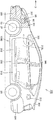
도 1은, 본 실시형태에 관한 하이브리드 차량의 개략 구성을 나타내는 사시도,
도 2는, 도 1의 개략 구성을 나타내는 블록도,
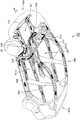
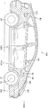
도 3은, 하이브리드 차량의 차량 본체의 보디(body)의 개략 구성을 나타내는 사시도,
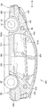
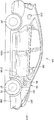
도 4는, 하이브리드 차량의 측면도,
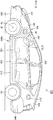
도 5는, 본 실시형태에 관한 하이브리드 차량의 제 1 변형예를 나타내는 측면도,
도 6은, 본 실시형태에 관한 하이브리드 차량의 제 2 변형예를 나타내는 측면도,
도 7은, 본 실시형태에 관한 하이브리드 차량의 제 3 변형예를 나타내는 측면도,
도 8은, 충전·급전부 및 급유부를 운전석측의 측면에 설치한 예를 나타내는 블록도,
도 9는, 본 실시형태에 관한 하이브리드 차량의 제 4 변형예를 나타내는 측면도,
도 10은, 본 실시형태에 관한 하이브리드 차량의 제 5 변형예를 나타내는 측면도,
도 11은, 본 실시형태에 관한 하이브리드 차량의 제 6 변형예를 나타내는 측면도,
도 12는, 본 발명의 실시형태에 의한 하이브리드 차량의 개략 블록도이고, 외부 급전에 대한 설명도,
도 13은, 본 발명의 실시형태에 의한 하이브리드 차량의 개략 블록도이고, 배터리로의 충전에 대한 설명도,
도 14는, 프레임 부착 보디의 일부를 나타내는 사시도,
도 15는, 도 14에 나타낸 프레임 부착 보디의 프레임을 나타내는 평면도,
도 16은, 본 발명을 연료전지 차량에 적용하였을 때의 구성을 모식적으로 나타내는 모식도,
도 17은, 접속부 및 그 주위의 구성을 나타내는 사시도,
도 18은, 접속부 및 그 주위의 구성을 나타내는 사시도이다. 1 is a perspective view showing a schematic configuration of a hybrid vehicle according to the present embodiment;
2 is a block diagram showing the schematic configuration of FIG. 1;
3 is a perspective view showing a schematic configuration of a body of a vehicle body of a hybrid vehicle;
4 is a side view of the hybrid vehicle,
5 is a side view showing a first modification of the hybrid vehicle according to the present embodiment;
6 is a side view showing a second modified example of the hybrid vehicle according to the present embodiment;
7 is a side view showing a third modification of the hybrid vehicle according to the present embodiment;
8 is a block diagram showing an example in which the charging / feeding unit and the oil supply unit are provided on the side surface of the driver's seat;
9 is a side view showing a fourth modified example of the hybrid vehicle according to the present embodiment;
10 is a side view showing a fifth modification of the hybrid vehicle according to the present embodiment;
11 is a side view showing a sixth modified example of the hybrid vehicle according to the present embodiment;
12 is a schematic block diagram of a hybrid vehicle according to an embodiment of the present invention.
13 is a schematic block diagram of a hybrid vehicle according to an embodiment of the present invention, and an explanatory diagram of charging with a battery.
14 is a perspective view showing a part of a body with a frame,
FIG. 15 is a plan view showing a frame of the body with a frame shown in FIG. 14; FIG.
FIG. 16 is a schematic diagram schematically showing a configuration when the present invention is applied to a fuel cell vehicle; FIG.
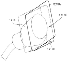
17 is a perspective view showing a connection portion and a configuration around it;
18 is a perspective view illustrating a structure of a connecting portion and its surroundings.
이하, 본 발명의 실시형태에 대하여, 도면을 참조하면서 상세하게 설명한다. 또, 도면에서 동일 또는 상당 부분에는 동일 부호를 붙이고 그 설명은 반복하지 않는다. EMBODIMENT OF THE INVENTION Hereinafter, embodiment of this invention is described in detail, referring drawings. In addition, the same code | symbol is attached | subjected to the same or equivalent part in drawing, and the description is not repeated.
도 1 내지 도 13을 이용하여, 본 실시형태에 관한 하이브리드 차량(100)에 대하여 설명한다. 도 1은, 본 실시형태에 관한 하이브리드 차량(100)의 개략 구성을 나타내는 사시도이고, 도 2는, 도 1의 개략 구성을 나타내는 블록도이다. 그리고, 도 3은, 하이브리드 차량(100)의 차량 본체(200)의 보디(500)의 개략 구성을 나타내는 사시도이다. A
도 1에서, 하이브리드 차량(100)은, 보디와 외장 부품으로 형성된 차량 본체(200)와, 하이브리드 차량(100)의 진행방향(D) 전방측에 설치된 한 쌍의 전륜(차륜)(2F)과, 진행방향(D) 후방측에 설치된 후륜(차륜)(2R)을 구비하고 있다. In FIG. 1, the
차량 본체(200)는, 하이브리드 차량(100)의 진행방향 전방(D)에 설치된 엔진 컴파트먼트(ER)와, 이 엔진 컴파트먼트(ER)에 대하여 진행방향(D) 후방측에 인접하는 탑승자 수용실(CR)과, 탑승자 수용실(CR)에 대하여 진행방향(D) 후방측에 인접하는 수하물실(LR)을 구비하고 있다. The vehicle
그리고, 도 3에 나타내는 바와 같이, 차량 본체(200)의 보디(500)로서는, 예를 들면, 모노코크 보디(unitized body)가 채용되어 있다. 이 보디(500)는, 진행방향(D)의 전면측에 설치되고, 엔진 컴파트먼트(ER)를 규정하는 프론트 벽부(550)와, 탑승자 수용실(CR)을 규정하는 수용벽부(560)와, 이 수용벽부(560)에 대하여, 차량 본체(200)의 진행방향(D) 후방측에 설치된 후방벽부(570)를 구비하고 있다. And as shown in FIG. 3, the monocoque body (unitized body) is employ | adopted as the
프론트 벽부(550)는, 차량 본체(200)의 전면에 설치되어, 차량 본체(200)의 폭방향으로 연장되는 프론트 아암부(501)와, 프론트 아암부(501)의 양쪽 끝부에 연설(連設)되어, 엔진 컴파트먼트(ER)의 측면부를 규정하는 프론트 측벽부(504)와, 엔진 컴파트먼트(ER)와 탑승자 수용실(CR)을 구획하는 프론트 구획 벽부(510)를 구비하고 있다. The
프론트 측벽부(504)는, 프론트 아암부(501)측으로부터 프론트 구획 벽부(510)를 향함에 따라, 높이방향의 폭이 커지도록 형성되어 있고, 프론트 측벽부(504)의 길이방향 중앙부는, 전륜(2F)을 받아들임 가능하도록 만곡되어 있다. The front
또 프론트 측벽부(504)는, 프론트 아암부(501)측으로부터 프론트 구획 벽부(510)측을 향함에 따라, 두께가 두꺼워지도록 형성되어 있다. Moreover, the front
그리고, 수용벽부(560)는, 프론트 구획 벽부(510)의 폭방향 양쪽 끝에 위치하는 측변부에 설치되어, 차량 본체(200)의 높이방향으로 수직 하강하는 프론트 지지부(503)와, 이 프론트 지지부(503)의 상단부에 접속된 프론트 필러(507)와, 프론트 지지부(503)의 하단부에 접속된 언더 지지부(505)를 구비하고 있다. And the receiving
보디(500)의 측면에는, 탑승자 수용실(CR)에 연통하여, 탑승자가 출입 가능한 개구부(212L, 212R)가 형성되어 있고, 이 개구부(212L, 212R)의 둘레 가장자리부는 프론트 지지부(503)와, 언더 지지부(505)와, 프론트 필러(507)와, 후방벽부(570)의 가장자리부에 의하여 규정되어 있다.
여기서, 보디(500) 중, 탑승자 수용실(CR)보다도 진행방향(D)의 전방측에 위치하는 부분의 두께는, 진행방향(D) 후방측에 위치하는 부분의 두께보다도 얇게 되어 있다. 이것에 의하여, 보디(500)는, 전면 충돌시에 있어서, 보디(500)의 전면측이 변형되어, 충격을 흡수하여, 탑승자 수용실(CR) 내를 보호 가능하게 되어 있다. Here, the thickness of the part of the
이와 같이 구성된 보디(500)의 표면에, 복수의 외장 부품을 장착하여, 차량 본체(200)가 구성되어 있다. The
외장 부품으로서는, 예를 들면, 도 1에서, 차량 본체(200)의 전면측에 설치된 프론트 페이스(310)와, 이 프론트 페이스(310)의 아래쪽에 설치된 프론트 범퍼(300)와, 도 3에 나타내는 프론트 측벽부(504)를 덮도록 설치된 프론트 펜더(301)와, 개구부(212L, 212R)를 개폐 가능하게 설치된 프론트 도어(312) 및 리어 도어(313)를 구비하고 있다. As an exterior part, for example, in FIG. 1, the
또, 외장 부품으로서는, 엔진 컴파트먼트(ER)의 상부 덮개로서의 후드(307)와, 리어 도어(313)에 대하여 진행방향(D) 후방측에 설치된 리어 펜더(303)와, 리어 펜더(303)의 아래쪽에 설치된 리어 범퍼(304)를 구비하고 있다. Moreover, as an exterior component, the
탑승자 수용실(CR)에는, 하이브리드 차량(100)을 조작하는 운전석(DR)과, 운전석에 대하여 하이브리드 차량(100)의 폭방향에 인접하는 보조석과, 이 보조석 및 운전석(DR)의 뒤쪽에 설치된 후부 좌석이 설치되어 있다. 이 도 1에 나타내는 예에서는, 운전석(DR)은, 진행방향(D)으로 연장되는 하이브리드 차량(100)의 중심선(O)에 대하여 하이브리드 차량(100)의 우측면(한쪽 측면)(100A)측에 오프셋하고 있다. In the occupant accommodation chamber CR, a driver's seat DR for operating the
그리고, 도 1에 나타내는 바와 같이, 탑승자 수용실(CR) 내의 후부 좌석 밑에 위치하는 부분에는, 가솔린 등의 액체연료가 수용되는 퓨엘탱크(201)가 설치되고, 후부 좌석보다 진행방향(D) 뒤쪽에는, 연료전지 또는 대용량의 커패시터 등의 배터리(축전기)(B)가 배치되어 있다. 1, the
엔진 컴파트먼트(ER) 내에는, 전륜(2F)을 구동하는 동력을 발생하는 내연기관의 엔진(4)과, 트랜스액슬(TR)이 수용되어 있다. In the engine compartment ER, the
트랜스액슬(TR)은, 전륜(2F)를 구동하는 전동기(MG1, MG2)와, 배터리(B)로부터의 전력을 고압하는 승압 컨버터(20)와, 승압 컨버터(20)로부터의 직류전력을 교류전력으로 변환하여 전동기(MG1, MG2)에 공급하는 인버터(30, 40)와, 플래니터리 기어 등으로 형성된 동력 분할기구(3)를 포함한다. The transaxle TR alternates the electric motors MG1 and MG2 for driving the
엔진(4)은, 중심선(O)에 대하여 측면(100A)측에 오프셋 되어 있고, 트랜스액슬(TR)은, 측면(100B)측에 오프셋 되어 있다. 이를 위하여, 엔진(4)과 트랜스액슬(TR)을 일체적으로 보았을 때의 중심은, 중심선(O) 상 또는 그 근방에 위치하여, 하이브리드 차량(100)의 폭방향의 밸런스가 잡혀 있다. The
또한, 배터리(B) 및 퓨엘탱크(201)의 중심은, 어느 것이나, 중심선(O) 상 또는 그 근방에 위치하고 있다. The centers of the battery B and the
여기서, 하이브리드 차량(100)의 측면 중, 운전석(DR)이 근접하는 측면(100A)과 반대측에 위치하는 측면(100B)에 충전·급전부(전력 입출력부)(90) 및 급유부(213)가 설치되어 있다. 운전석(DR)에는, 전륜(2F)을 조작하기 위한 스티어링, 스티어링 샤프트, 스티어링 기어 등이 설치되어 있다.Here, among the side surfaces of the
그리고, 충전·급전부(90) 및 급유부(213)에 의하여, 운전석(DR)과의 중량 밸런스가 잡혀 있다. The weight balance with the driver's seat DR is achieved by the charging /
이 도 1에 나타내는 예에서는, 충전·급전부(90)는, 보디(500)에 설치되어, 커넥터(190)가 삽입 가능한 개구부를 가지는 접속부(91)와, 프론트 펜더(301)에 설치되어, 접속부(91)의 개구부를 개폐 가능한 덮개부(90A)와, 접속부(91)에 접속된 배선(92)을 구비하고 있다. 커넥터(190)로서는, 충전용 커넥터와, 급전용 커넥터와, 충전·급전용 커넥터 중 어느 것이나 포함한다. In the example shown in FIG. 1, the charging /
그리고, 충전용 커넥터로서는, 상용 전원(예를 들면, 일본에서는 단상교류 100V)으로부터 공급되는 전력으로 배터리(B)를 충전하기 위한 커넥터이다. 이 충전용 커넥터로서는, 예를 들면, 일반 가정용 전원에 접속된 콘센트 등을 들 수 있다. The charging connector is a connector for charging the battery B with electric power supplied from a commercial power supply (for example, single-phase AC 100V in Japan). As this charging connector, an outlet etc. connected to the general household power supply are mentioned, for example.
급전용 커넥터는, 하이브리드 차량(100)으로부터의 전력(예를 들면, 일본에서는 단상교류 100V)을 외부 부하로 공급하기 위한 커넥터이다. 또한, 충전·급전용 커넥터는, 상기 충전용 커넥터 및 급전용 커넥터 중 어느 하나의 기능을 가지는 커넥터이고, 상용 전원으로부터 공급되는 전력을 배터리에 충전 가능함과 동시에, 하이브리드 차량(100)으로부터의 전력을 외부 부하로 공급 가능한 커넥터이다. The power supply connector is a connector for supplying electric power from the hybrid vehicle 100 (for example, single-phase AC 100V in Japan) to an external load. In addition, the connector for charging and feeding is a connector having a function of any one of the above-mentioned charging connector and the power feeding connector, and it is possible to charge power supplied from a commercial power source to a battery and to supply power from the
또한, 커넥터(190)와 충전·급전부(90)의 사이에 있어서의 전력에 수수방법으로서는, 커넥터(190)의 일부와 충전·급전부(90)의 적어도 일부가 직접 접촉하는 접촉형(컨택티브)이어도 되고, 또, 비접촉형(인덕티브)이어도 된다. In addition, as a transfer method to the electric power between the
배선(92)은, 전동기(MG1, MG2)의 중성점에 접속되어 있고, 커넥터(190)로부터 공급된 전력은, 전동기(MG1, MG2) 및 인버터(30, 40) 및 승압 컨버터(20)를 거쳐, 배터리(B)에 공급 가능하게 되어 있다. The
또, 충전·급전부(90)는, 배터리(B)에 축전된 전력을 승압 컨버터(20) 및 인버터(30, 40)를 거쳐, 커넥터(190)로부터 외부에 급전 가능하게 되어 있다. In addition, the charging /
또, 이 도 1에 나타내는 예에서는, 급유부(213)는, 보디(500)에 설치되어, 개구부를 가지는 노즐 받아들임부(215)와, 이 노즐 받아들임부(215) 및 퓨엘탱크(201)에 접속된 급유관(214)과, 외장 부품에 설치되어, 노즐 받아들임부(215)의 개구부를 개폐 가능한 덮개부(213A)를 구비하고 있다. In addition, in the example shown in this FIG. 1, the
그리고, 노즐 받아들임부(215)는, 하이브리드 차량(100)의 외부에 설치된 급유 커넥터(191)의 급유 노즐을 받아들임 가능하게 되어 있다. 그리고, 급유된 가솔린 등의 연료는, 급유관(214)을 거쳐, 퓨엘탱크(201)에 공급된다. And the
이와 같이, 급유부(213) 및 충전·급전부(90)가 하이브리드 차량(100)의 동일 측면(100B)에 설치되어 있기 때문에, 운전자는, 충전·급전부(90) 및 급유부(213)의 위치를 기억하기 쉽다. 이 때문에, 충전·급유 스탠드 등에 하이브리드 차량(100)을 진입시킬 때에, 하이브리드 차량(100)의 진입·정차방향을 틀리는 것을 저감할 수 있다. Thus, since the
도 4는, 하이브리드 차량(100)의 측면도이다. 이 도 4에서, 충전·급전부(90)는, 하이브리드 차량(100)의 측면(100B) 중 어느 위치에 설치되어도 된다. 예를 들면, 리어 범퍼(304)의 측면부, 리어 펜더(303), 리어 도어(313), 프론트 도어(312), 프론트 펜더(301), 프론트 범퍼(300)의 측면부, 센터 필러(305), 프론트 필러(302) 및 언더 필러(306) 중 어느 위치이어도 된다. 또, 마찬가지로, 급유부(213)도, 측면(100B) 중 어느 위치에 설치되어도 된다. 4 is a side view of the
여기서, 충전·급전부(90)는, 측면(100B) 중, 개구부(212L)에 대하여 진행방향(D)의 전방측에 위치하는 영역(R1) 또는 개구부(212L)에 대하여 진행방향(D)의 후방측에 위치하는 영역(R2)에 설치되고, 급유부(213)는, 개구부(212L)에 대하여, 충전·급전부(90)와 반대측에 위치하는 영역(R1, R2)에 설치하여도 된다. Here, the charging /
이것에 의하여, 충전·급전부(90)와 급유부(213)의 사이에, 개구부(212L)가 위치하게 되고, 충전·급전부(90)와 급유부(213)가 진행방향(D)과 떨어져 위치하게 된다. 이 때문에, 운전자 등이 각 작업을 행할 때에, 충전·급전부(90)와 급유부(213)를 혼동하는 것을 억제할 수 있다. As a result, the
또, 충전·급전부(90)와 급유부(213)를 떨어지게 위치시킴으로써, 보디(500)에 형성되어, 충전·급전부(90)의 접속부(91)가 삽입되는 구멍부와, 급유부(213)의 노즐 받아들임부(215)가 삽입되는 구멍부를 떨어지게 할 수 있어, 보디(500)에 국소적으로 강성이 낮은 부분이 형성되는 것을 억제할 수 있다. In addition, by placing the charging /
이것에 의하여, 보디(500) 중, 경시적으로 열화하기 쉬운 부분이 형성되는 것을 억제할 수 있다. 또한, 영역(R1)은, 프론트 펜더(301) 및 프론트 범퍼(300)의 측면부를 포함하는 영역이고, 영역(R2)은, 리어 펜더(303) 및 리어 범퍼(304)의 측면부를 포함하는 영역이다. Thereby, formation of the part which is easy to deteriorate over time in the
여기서, 급유부(213)의 노즐 받아들임부(215)는, 급유 커넥터(191)의 급유 노즐이 삽입되고, 급유 노즐을 거쳐 급유 커넥터(191)를 지지한다. 이 급유 커넥터(191)는, 내부에 급유 속도를 조정하기 위한 조정기구가 일반적으로 설치되어 있고, 커넥터(190)보다 중량이 무겁게 되어 있다. Here, the
이와 같이 중량이 무거운 급유 커넥터(191)를 지지하는 급유부(213)는, 접속부(91)보다 강성이 높게 형성된다. 특히, 급유부(213)는, 급유관(214)을 지지하고 있어, 배선(92)이 접속된 접속부(91)보다 강성을 높게 구성할 필요가 있다. Thus, the
그래서, 강성이 낮은 접속부(91)를 영역(R1)에 위치시킴으로써, 보디(500)의 전면측의 강성이 너무 높아지는 것을 억제하여, 보디(500)의 충격 흡수 기능을 확보할 수 있다. 즉, 충전·급전부(90)의 주위에 위치하는 보디(500)의 두께는, 급유부(213)의 주위에 위치하는 부분의 보디(500)의 두께보다 얇게 되어 있다. Therefore, by placing the
또한, 일반적으로, 급유부(213)는, 측면(100B) 중, 개구부(212L)보다 후방측에 설치되어 있는 것이 널리 인식되어 있기 때문에, 급유부(213)를 개구부(212L)보다 후방측에 설치함으로써, 운전자의 오인을 억제할 수 있다. In addition, since it is generally recognized that the
그리고, 도 1에 나타내는 바와 같이, 퓨엘탱크(201)를, 후부 좌석 하측에 배치함과 동시에, 급유부(213)를 영역(R2) 내에 위치시킴으로써, 급유관(214)의 길이를 저감할 수 있다. As shown in FIG. 1, the
또한, 도 1에 나타내는 바와 같이, 엔진 컴파트먼트(ER) 내에 전동기(MG1, MG2)를 설치함과 동시에, 도 4에 나타내는 바와 같이, 영역(R1) 내에 충전·급전부(90)를 설치함으로써, 배선(92)의 길이를 저감할 수 있다. As shown in FIG. 1, the electric motors MG1 and MG2 are provided in the engine compartment ER, and the charging /
또, 도 5에 나타내는 바와 같이, 바람직하게는, 측면(100B) 중, 전륜(2F)에 접속된 샤프트(53)보다도 진행방향(D) 후방측으로서, 개구부(212L)의 개구 가장자리부보다도 진행방향(D) 전방측에 위치하는 영역(R3)에 충전·급전부(90)를 설치한다. 도 3에 나타내는 보디(500) 중, 영역(R3)이 위치하는 프론트 측벽부(504)는, 진행방향(D) 후방측을 향함에 따라, 강성이 높아지도록 형성되어 있고, 충전·급전부(90)의 접속부(91)를 양호하게 지지 가능한 정도의 강성을 가지고 있다. 이 때문에, 반복하여, 충전·외부 급전작업을 행하였다고 해도, 프론트 측벽부(504)의 경시적 열화를 억제할 수 있다.Moreover, as shown in FIG. 5, Preferably, it advances rather than the opening edge part of the
또, 도 6에 나타내는 바와 같이, 바람직하게는, 측면(100B) 중, 개구부(212L)의 개구 가장자리부와 진행방향(D)의 선단부까지의 사이에 위치하는 영역으로서, 전륜(2F)의 상단부보다 위쪽에 위치하는 영역(R4)에, 충전·급전부(90)를 설치한다. Moreover, as shown in FIG. 6, Preferably, the upper end part of the
이것에 의하여, 충전·급전부(90)가, 도 1에 나타내는 커넥터(190)를 꽂기 쉬운 위치에 위치하게 되어, 충전, 외부 급전작업을 효율적으로 행할 수 있다. As a result, the charging /
또, 도 7에 나타내는 바와 같이, 바람직하게는, 충전·급전부(90)는, 측면(100B) 중, 샤프트(53)보다 진행방향(D) 전방측의 영역(R5)에 설치한다. 이와 같은 위치에, 충전·급전부(90)를 설치함으로써, 도 1에 나타내는 커넥터(190)를 충전·급전부(90)에 꽂은 상태에서, 프론트 도어(312)를 개방하였을 때에, 커넥터(190)의 배선과 프론트 도어(312)의 접촉을 억제할 수 있다. Moreover, as shown in FIG. 7, Preferably, the charging / feeding
도 8은, 충전·급전부(90) 및 급유부(213)를 운전석(DR)측의 측면(100A)에 설치한 예를 나타내는 블록도이고, 도 9는, 충전·급전부(90) 및 급유부(213)를 운전석(DR)측의 측면(100A)에 설치한 예를 나타내는 측면도이다. FIG. 8 is a block diagram showing an example in which the charging /
이 도 9에 나타내는 바와 같이, 충전·급전부(90) 및 급유부(213)는, 어느 것이나 측면(100A)에 설치되고, 운전석(DR)에 근접하는 위치에 설치되어 있기 때문에, 운전석(DR)에서 운전자가 내려, 충전·급전작업을 행할 때에, 바로 작업에 착수할 수 있다. As shown in FIG. 9, since the charging /
그리고, 충전·급전부(90) 및 급유부(213)는, 측면(100A) 중 어느 위치에 설치되어도 된다. The charging /
이 도 9에 나타내는 예에서는, 충전·급전부(90)는, 측면(100A) 중, 운전석(DR)측의 개구부(212R)의 개구 가장자리부보다, 진행방향(D) 전방에 위치하는 영역(R6) 내에 설치되어 있다. 그리고, 급유부(213)는, 측면(100A) 중, 개구부(212R)의 개구 가장자리부보다, 진행방향(D) 후방측에 위치하는 영역(R7)에 설치되어 있다. In the example shown in this FIG. 9, the charging /
이와 같이, 충전·급전부(90)와, 급유부(213)의 사이에 개구부(212R)가 위치하고 있어, 충전·급전부(90)와, 급유부(213)의 혼동을 억제할 수 있음과 동시에, 보디(500)의 충격 흡수 기능을 확보할 수 있다. Thus, the
또, 도 10에 나타내는 예에서는, 충전·급전부(90)는, 측면(100A) 중, 샤프트(53)에 대하여 진행방향(D)의 후방측으로서, 개구부(212R)의 개구 가장자리부보다도, 진행방향(D) 전방측에 위치하는 영역(R8)에 설치되어 있다. In addition, in the example shown in FIG. 10, the charging / feeding
이 예에서는, 상기 도 5에 나타내는 예와 마찬가지로, 반복하여, 충전·외부 급전작업을 행하였다고 해도, 프론트 측벽부(504)의 경시적 열화를 억제할 수 있다. In this example, deterioration with time of the front
도 11에 나타내는 예에서는, 충전·급전부(90)는, 측면(100A) 중, 개구부(212R)의 개구 가장자리부보다 진행방향(D)의 전방측에 위치하는 영역으로서, 전륜(2F)보다 위쪽에 위치하는 영역(R9)에 설치되어 있다. In the example shown in FIG. 11, the charging / feeding
이 예에서는, 상기 도 6에 나타내는 예와 마찬가지로, 충전·외부 급전작업 및 급유작업을 용이하게 행할 수 있다. In this example, similarly to the example shown in FIG. 6, the filling / external feeding operation and the oil supply operation can be easily performed.
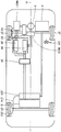
도 12는, 본 발명의 실시형태에 의한 하이브리드 차량(100)의 개략 블록도이다. 이 도 12를 이용하여, 커넥터(190)로부터의 교류전류를 배터리(B)에 충전하는 방법에 대하여 설명한다. 12 is a schematic block diagram of a
배터리(B)의 양(+)의 전극은, 양극선(PL1)에 접속되고, 배터리(B)의 음(-)의 전극은, 음극선(NL1)에 접속된다. 콘덴서(C1)는, 양극선(PL1)과 음극선(NL1)의 사이에 접속된다. 승압 컨버터(20)는, 양극선(PL1) 및 음극선(NL1)과 양극선(PL2) 및 음극선(NL2)의 사이에 접속된다. 콘덴서(C2)는, 양극선(PL2)과 음극선(NL2)의 사이에 접속된다. 인버터(30)는, 양극선(PL2) 및 음극선(NL2)과 전동기(MG1)의 사이에 접속된다. 인버터(40)는, 양극선(PL2) 및 음극선(NL2)과 전동기(MG2)의 사이에 접속된다. The positive electrode of the battery B is connected to the positive electrode line PL1, and the negative electrode of the battery B is connected to the negative electrode line NL1. The capacitor C1 is connected between the anode line PL1 and the cathode line NL1. The
전동기(MG1)는, 3상 코일(11)을 스테이터 코일로서 구비하고, 전동기(MG2)는, 3상 코일(12)을 스테이터 코일로서 구비한다. The motor MG1 includes the three-
승압 컨버터(20)는, 리액터(L1)와, NPN 트랜지스터(Q1, Q2)와, 다이오드(D1, D2)를 포함한다. 리액터(L1)의 한쪽 끝은 양극선(PL1)에 접속되고, 다른쪽 끝은 NPN 트랜지스터(Q1)와 NPN 트랜지스터(Q2)의 중간점, 즉, NPN 트랜지스터(Q1)의 에미터와 NPN 트랜지스터(Q2)의 콜렉터의 사이에 접속된다. NPN 트랜지스터(Q1, Q2)는, 양극선(PL1)과 음극선(NL1, NL2)의 사이에 직렬로 접속된다. 그리고, NPN 트랜지스터(Q1)의 콜렉터는, 인버터(30, 40)의 양극선(PL2)에 접속되고, NPN 트랜지스터(Q2)의 에미터는 음극선(NL1, NL2)에 접속된다. 또, 각 NPN 트랜지스터(Q1, Q2)의 콜렉터-에미터 사이에는, 에미터측에서 콜렉터측으로 전류를 흘리는 다이오드(D1, D2)가 각각 배치되어 있다. The
인버터(30)는, U상 아암(31)과, V상 아암(32)과, W상 아암(33)으로 이루어진다. U상 아암(31), V상 아암(32) 및 W상 아암(33)은, 양극선(PL2)과 음극선(NL2)의 사이에 병렬로 설치된다. The
U상 아암(31)은, 직렬 접속된 NPN 트랜지스터(Q3, Q4)로 이루어지고, V상 아암(32)은, 직렬 접속된 NPN 트랜지스터(Q5, Q6)로 이루어지며, W상 아암(33)은, 직렬 접속된 NPN 트랜지스터(Q7, Q8)로 이루어진다. 또, 각 NPN 트랜지스터(Q3∼Q8)의 콜렉터-에미터 사이에는, 에미터측에서 콜렉터측으로 전류를 흘리는 다이오드(D 3∼D8)가 각각 접속되어 있다. The
인버터(30)의 각 상 아암의 중간점은, 전동기(MG1)에 포함되는 3상 코일(11)의 각 상 코일의 각 상 끝에 접속되어 있다. 즉, 전동기(MG1)는, 3상의 영구자석 모터이고, U, V, W상의 3가지 코일의 한쪽 끝이 중성점(M1)에 공통 접속되어 구성되며, U상 코일의 다른쪽 끝이 NPN 트랜지스터(Q3, Q4)의 중간점에, V상 코일의 다른쪽 끝이 NPN 트랜지스터(Q5, Q6)의 중간점에, W상 코일의 다른쪽 끝이 NPN 트랜지스터(Q7, Q8)의 중간점에 각각 접속되어 있다. The intermediate point of each phase arm of the
인버터(40)는, 콘덴서(C2)의 양쪽 끝에 인버터(30)와 병렬로 접속된다. 그리고, 인버터(40)는, U상 아암(41)과, V상 아암(42)과, W상 아암(43)으로 이루어진다. U상 아암(41), V상 아암(42), W상 아암(43)은, 양극선(PL2)과 음극선(NL2)의 사이에 병렬로 설치된다. The
U상 아암(41)은, 직렬 접속된 NPN 트랜지스터(Q9, Q10)로 이루어지고, V상 아암(42)은, 직렬 접속된 NPN 트랜지스터(Q11. Q12)로 이루어지며, W상 아암(43)은, 직렬 접속된 NPN 트랜지스터(Q13, Q14)로 이루어진다. NPN 트랜지스터(Q9∼Q14)는, 각각, 인버터(30)의 NPN 트랜지스터(Q3∼Q8)에 상당한다. 즉, 인버터(40)는, 인버터(30)와 동일한 구성으로 이루어진다. 그리고, NPN 트랜지스터(Q9∼Q14)의 콜렉터-에미터 사이에는, 에미터측에서 콜렉터측으로 전류를 흘리는 다이오드(D9∼D14)가 각각 접속되어 있다. The
인버터(40)의 각 상 아암의 중간점은, 전동기(MG2)에 포함되는 3상 코일(12)의 각 상 코일의 각 상 끝에 접속되어 있다. 즉, 전동기(MG2)도, 3상의 영구자석 모터이고, U, V, W상의 3개의 코일의 한쪽 끝이 중성점(M2)에 공통 접속되어 구성되며, U상 코일의 다른쪽 끝이 NPN 트랜지스터(Q9, Q10)의 중간점에, V상 코일의 다른쪽 끝이 NPN 트랜지스터(Q11, Q12)의 중간점에, W상 코일의 다른쪽 끝이 NPN 트랜지스터(Q13, Q14)의 중간점에 각각 접속되어 있다.The intermediate point of each phase arm of the
배터리(B)는, 니켈 수소 또는 리튬 이온 등의 2차 전지로 이루어진다. 전압 센서(10)는, 배터리(B)로부터 출력되는 배터리 전압(Vb)를 검출하고, 그 검출한 배터리 전압(Vb)을 제어장치(70)로 출력한다. 시스템 릴레이(SR1, SR2)는, 제어장치(70)로부터의 신호(SE)에 의하여 온/오프된다. 더욱 구체적으로는, 시스템 릴레이(SR1, SR2)는, 제어장치(70)로부터의 H(논리 하이) 레벨의 신호(SE)에 의하여 온되고, 제어장치(70)로부터의 L(논리 로우) 레벨의 신호(SE)에 의하여 오프된다. 콘덴서(C1)는, 배터리(B)로부터 공급된 직류전압을 평활화하고, 그 평활화한 직류전압을 승압 컨버터(20)로 공급한다. The battery B consists of secondary batteries, such as nickel hydrogen or lithium ion. The
승압 컨버터(20)는, 콘덴서(C1)로부터 공급된 직류전압을 승압하여 콘덴서(C2)로 공급한다. 더욱 구체적으로는, 승압 컨버터(20)는, 제어장치(70)로부터 신호(PWC)를 받으면, 신호(PWC)에 의하여 NPN 트랜지스터(Q2)가 온된 기간에 따라 직류전압을 승압하여 콘덴서(C2)에 공급한다. 이 경우, NPN 트랜지스터(Q1)는, 신호(PWC)에 의하여 오프되어 있다. 또, 승압 컨버터(20)는, 제어장치(70)로부터의 신호(PWC)에 따라, 콘덴서(C2)를 거쳐 인버터(30 및/또는 40)로부터 공급된 직류전압을 강압하여 배터리(B)를 충전한다. The
콘덴서(C2)는, 승압 컨버터(20)로부터의 직류전압을 평활화하고, 그 평활화한 직류전압을 인버터(30, 40)로 공급한다. 전압 센서(13)는, 콘덴서(C2)의 양쪽 끝의 전압, 즉, 승압 컨버터(20)의 출력전압(Vm)[인버터(30, 40)로의 입력 전압에 상당한다. 이하 동일.]을 검출하고, 그 검출한 출력전압(Vm)을 제어장치(70)로 출력한다. The capacitor C2 smoothes the DC voltage from the
인버터(30)는, 콘덴서(C2)로부터 직류전압이 공급되면 제어장치(70)로부터의 신호(PWM1)에 의거하여 직류전압을 교류전압으로 변환하여 전동기(MG1)를 구동한다. 이것에 의하여, 전동기(MG1)는, 토오크 지령값(TR1)에 의하여 지정된 토오크를 발생하도록 구동된다. 또, 인버터(30)는, 동력 출력장치가 탑재된 하이브리드 자동차의 회생 제동시, 전동기(MG1)가 발전한 교류전압을 제어장치(70)로부터의 신호(PWM1)에 의거하여 직류전압으로 변환하고, 그 변환한 직류전압을 콘덴서(C2)를 거쳐 승압 컨버터(20)로 공급한다. 또한, 여기서 말하는 회생 제동이란, 하이브리드 자동차를 운전하는 운전자에 의한 풋 브레이크 조작이 있었던 경우의 회생 발전을 따르는 제동이나, 풋 브레이크를 조작하지 않으나, 주행 중에 액셀러레이터 페달을 오프함으로써 회생 발전을 시키면서 차량을 감속(또는 가속의 중지)시키는 것을 포함한다. When the DC voltage is supplied from the capacitor C2, the
또한, 인버터(30)는, 제어장치(70)로부터의 신호(PWM1)에 따라, 충전·급전부(90)의 단자(61, 62)로부터, 상용 전원용 교류전압(VAC)을 출력 가능하도록 전동기(MG1)를 구동한다. In addition, the
인버터(40)는, 콘덴서(C2)로부터 직류전압이 공급되면 제어장치(70)로부터의 신호(PWM2)에 의거하여 직류전압을 교류전압으로 변환하여 전동기(MG2)를 구동한다. 이것에 의하여, 전동기(MG2)는, 토오크 지령값(TR2)에 의하여 지정된 토오크 를 발생하도록 구동된다. 또, 인버터(40)는, 동력 출력장치가 탑재된 하이브리드 자동차의 회생 제동시, 전동기(MG2)가 발전한 교류전압을 제어장치(70)로부터의 신호(PWM2)에 의거하여 직류전압으로 변환하고, 그 변환한 직류전압을 콘덴서(C2)를 거쳐 승압 컨버터(20)로 공급한다. When the DC voltage is supplied from the capacitor C2, the
또한, 인버터(40)는, 제어장치(70)로부터의 신호(PWM2)에 따라, 상용 전원용의 교류전압(VAC)을 충전·급전부(90)의 단자(61, 62)로부터 출력 가능하도록 전동기(MG2)를 구동한다. In addition, the
전류 센서(14)는, 전동기(MG1)에 흐르는 모터 전류(MCRT1)를 검출하고, 그 검출한 모터 전류(MCRT1)를 제어장치(70)로 출력한다. 전류 센서(15)는, 전동기(MG2)에 흐르는 모터 전류(MCRT2)를 검출하고, 그 검출한 모터 전류(MCRT2)를 제어장치(70)로 출력한다. The
충전·급전부(90)는, 1차 코일(51)과 2차 코일(52)을 포함한다. 1차 코일(51)은, 전동기(MG1)에 포함되는 3상 코일(11)의 중성점(M1)과 전동기(MG2)에 포함되는 3상 코일(12)의 중성점(M2)과의 사이에 접속된다. 그리고, 충전·급전부(90)는, 전동기(MG1)의 중성점(M1)과 전동기(MG2)의 중성점(M2)과의 사이에 생긴 교류전압을 상용 전원용 교류전압(VAC)으로 변환하여 단자(61, 62)로부터 출력한다. The charging /
도 13은, 본 발명의 실시형태에 의한 하이브리드 차량(100)의 개략 블록도이다. 이 도 13을 이용하여, 커넥터(190)에 교류전류를 공급하여, 외부 급전하는 방법에 대하여 설명한다. 도 13에서, 3상 브리지 회로로 이루어지는 각 인버터(30, 40)에서는, 6개의 트랜지스터의 온/오프의 조합은 8 패턴 존재한다. 그 8개의 스위칭 패턴 중 2개는 상간 전압이 영(零)이 되고, 그와 같은 전압상태는 영전압 벡터라 부른다. 영전압 벡터에 대해서는, 상부 아암의 3개의 트랜지스터는 서로 동일한 스위칭 상태(모두 온 또는 오프)로 간주할 수 있고, 또, 하부 아암의 3개의 트랜지스터도 서로 동일한 스위칭 상태로 간주할 수 있다. 따라서, 이 도 13에서는, 인버터(30)의 상부 아암의 3개의 트랜지스터는 상부 아암(30A)으로서 통합하여 나타내고, 인버터(30)의 하부 아암의 3개의 트랜지스터는 하부 아암(30B)으로서 통합하여 나타내고 있다. 마찬가지로, 인버터(40)의 상부 아암의 3개의 트랜지스터는 상부 아암(40A)으로서 통합하여 나타내고, 인버터(40)의 하부 아암의 3개의 트랜지스터는 하부 아암(40B)으로서 통합하여 나타내고 있다. 13 is a schematic block diagram of a
도 13에 나타낸 바와 같이, 이 영상 등가회로는, 커넥터(190)의 전력 입력선 [ACL1(92), ACL2(92)]을 거쳐 중성점(M1, M2)에 부여되는 단상 교류 전력을 입력으로 하는 단상 PWM 컨버터로 볼 수 있다. 그래서, 인버터(30, 40)의 각각에 있어서 영전압 벡터를 변화시켜, 인버터(30, 40)를 단상 PWM 컨버터의 아암으로서 동작하도록 스위칭 제어함으로써, 전력 입력선(ACL1, ACL2)으로부터 입력되는 교류전력을 직류전력으로 변환하여 양극선(PL2)으로 출력할 수 있다. 그 변환한 직류전압을 콘덴서(C2)를 거쳐 승압 컨버터(20)로 공급하여, 배터리(B)에 충전한다. As shown in Fig. 13, this video equivalent circuit takes as input the single-phase AC power applied to the neutral points M1 and M2 via the power input lines [
본 실시에서는, 모노코크 보디를 가지는 하이브리드 차량에 적용한 경우에 대하여 설명하였으나, 이것에 한정되지 않는다. 도 14는, 프레임 부착 보디(600)의 일부를 나타내는 사시도이고, 도 15는, 도 14에 나타낸 프레임 부착 보디(600)의 프레임(650)을 나타내는 평면도이다. In this embodiment, the case where the present invention is applied to a hybrid vehicle having a monocoque body has been described, but the present invention is not limited thereto. FIG. 14: is a perspective view which shows a part of
도 14에 나타내는 예에서는, 프레임 부착 보디(600)는, 프레임(650)과, 이 프레임(650)의 상면에 고정된 박스형의 보디(610)를 구비하고 있다. In the example shown in FIG. 14, the frame attached
보디(610)의 프론트부(630)는, 엔진 컴파트먼트(ER)를 규정하고 있다. 그리고, 프론트부(630)는, 전면에 배치된 상측 서포트부(620)와, 하측 서포트부(621)와, 엔진 컴파트먼트(ER)의 측면을 규정하는 프론트 펜더부(622)를 구비하고 있다. The
상측 서포트부(620) 및 프론트 펜더부(622)의 상측 가장자리부는, 엔진 컴파트먼트(ER)의 개구부의 일부를 규정하고 있고, 하측 서포트부(621)는, 상측 서포트부(620)의 아래쪽에 배치되어 있다. The upper edge portion of the
그리고, 상측 서포트부(620)의 중앙부와, 프론트 펜더부(622)의 상측 가장자리부와, 하측 서포트부(621)의 중앙부는, 박판화가 도모되어 있고, 유연 구조로 되어 있음과 동시에, 경량화가 도모되어 있다. 이것에 의하여, 도시 생략한 후드 패널의 진동 증대를 억제할 수 있다. In addition, the center portion of the
그리고, 유연 구조로 된 프론트 펜더부(622)에는, 충전·급전부(90)가 설치되어 있다. 이것에 의하여, 도 1에 나타내는 바와 같은 급유부(213)가 설치된 경우보다도, 충전·급전부(90)를 설치한 쪽이, 프론트 펜더부(622)의 강성의 상승을 억제할 수 있어, 후드 패널의 진동 증대를 억제할 수 있다. And the
또한, 도 13에 나타내는 바와 같이, 프레임(650)은, 하이브리드 차량(100)의 진행방향(D)을 따라 연장되는 한 쌍의 사이드 프레임(651)과, 이 사이드 프레임(651) 사이에 설치된 복수의 사이드 지지부(652∼660)와, 상기 보디(610)와 프레임(650)을 고정하는 복수의 고정부(670)를 구비하고 있다. 프레임 부착 보디(600)는, 상기와 같은 프레임(650)을 구비하고 있기 때문에, 강성을 높게 확보할 수 있고, 예를 들면, 견인하는 것과 같은 경우에서도, 프레임(650)에 견인부를 설치함으로써, 프레임 부착 보디(600)의 변형 등을 억제할 수 있다. As shown in FIG. 13, the
또한, 본 실시형태에서는, 하이브리드 형식 중, 이른바 직렬/병렬형 하이브리드에 의거하여 설명을 행하였으나, 이 형식에 한정되는 것은 아니다. 즉, 급유가 필요한 내연기관으로서의 엔진과, 이 엔진에 의하여 발전된 전력 또는/및 배터리에 축전된 전력에 의하여 차륜을 구동시키는 주행용 모터를 구비한 하이브리드 형식(직렬형 하이브리드)에서도 적용할 수 있다. 또한, 엔진과 모터가 모두, 구동축에 동력을 출력 가능하게 된 병렬형 하이브리드에도 적용할 수 있다. In addition, in this embodiment, although description was based on what is called a series / parallel hybrid among the hybrid forms, it is not limited to this form. That is, the present invention can also be applied to a hybrid type (serial hybrid) having an engine as an internal combustion engine requiring lubrication, and a driving motor for driving a wheel by electric power generated by the engine and / or electric power stored in a battery. In addition, both the engine and the motor can be applied to a parallel hybrid in which power can be output to a drive shaft.
여기서, 본 실시형태에 관한 하이브리드 차량에서는, 배터리(B)에 대한 충전방법 및 외부 급전방법으로서는, 전동기(MG1, MG2)의 중성(M1, M2)을 사용하는 방법이 채용되어 있으나, 이것에 한정되지 않는다. 예를 들면, 인버터 기능과 DC/DC 컨버터의 기능을 가지는 충전/급전 전용장치를 설치하고, 충전/급전 전용장치를 사용하여, 충전·급전을 행하도록 하여도 된다. 이러한 충전/급전 전용장치는, 예를 들면, 도 12에서, 시스템 릴레이(SR1) 및 시스템 릴레이(SR2)와, 콘덴서(C1)의 사이에 접속된다. Here, in the hybrid vehicle according to the present embodiment, as the charging method for the battery B and the external power feeding method, a method of using the neutrals M1 and M2 of the electric motors MG1 and MG2 is employed, but the present invention is limited thereto. It doesn't work. For example, a charging / feeding exclusive device having an inverter function and a DC / DC converter may be provided, and charging and feeding may be performed using the charging / feeding exclusive device. Such a charge / power exclusive device is connected between the system relay SR1 and the system relay SR2 and the capacitor C1 in FIG. 12, for example.
또한, 본 실시형태에서는, 하이브리드 차량에 대하여 본 발명을 적용한 예에 대하여 설명하였으나, 이것에 한정되지 않는다. In addition, although the example which applied this invention to the hybrid vehicle was demonstrated in this embodiment, it is not limited to this.
예를 들면, 연료전지 차량에도 본 발명을 적용할 수 있다. For example, the present invention can be applied to a fuel cell vehicle.
도 16은, 본 발명을 연료전지 차량(1000)에 적용하였을 때의 구성을 모식적으로 나타내는 모식도이다. 이 도 16에 나타내는 바와 같이, 이 연료전지 차량(1000)은, 연료전지(1100)와, 커패시터 등의 축전기(1200)와, 주행용 인버터(1400)와, 보조기계용 인버터(1600)와, 보조기계 모터(1700)와, ECU(Electronic Control Unit)(1800)를 포함한다. 본 실시형태에 관한 전기 시스템의 제어장치는, 예를 들면 ECU(1800)가 실행하는 프로그램에 의하여 실현된다. FIG. 16 is a schematic diagram schematically showing a configuration when the present invention is applied to the
연료전지(1100)는, 수소와 공기 중의 산소를 화학반응시켜 발전한다. 연료전지(1100)로 발전된 전력은, 축전기(1200)에 축적되거나, 연료전지 차량(1000)에 탑재된 기기류에 의하여 소비된다. 또한, 연료전지(1100)에는, 주지의 일반적인 기술을 이용하면 되기 때문에, 여기서는 더 이상의 설명은 반복하지 않는다. The
축전기(1200)는, 예를 들면, 복수의 셀(전기 2중층 콘덴서)을 직렬로 접속하여 구성되어 있고, 2차 전지 등이어도 된다. 주행용 인버터(1400)는, 연료전지(1100) 및 축전기(1200)로부터 공급된 직류전력을 교류전력으로 변환하여, 주행용 모터(1500)를 구동시킨다. 회생 제동시에는, 주행용 모터(1500)로 발전된 교류전력을 직류전력으로 변환하여, 축전기(1200)에 공급한다. The
주행용 모터(1500)는, 3상 교류 회전전기이다. 그리고, 이 주행용 모터(1500)의 스테이터에는, U상 코일과, V상 코일과, W상 코일이 권회되어 있다. 그리고, U상 코일의 한쪽 끝과, V상 코일의 한쪽 끝부와, W상 코일의 한쪽 끝은, 중성점에서 서로 접속되어 있다. 또, U상 코일의 다른쪽 끝과, V상 코일의 다른쪽 끝과, W상 코일의 다른쪽 끝은, 각각, 주행용 인버터(1400)에 접속되어 있다. The traveling
그리고, 이 주행용 모터(1500)의 중성점에는, 접속부(제 2 접속부)(1090)의 배선(1192B)이 접속되어 있다. 이 접속부(1090)는, 예를 들면, 일반 가정용 전원 등의 교류전원에 접속된 커넥터(1190)가 접속 가능하게 되어 있다. 이 때문에, 주행용 모터(1500)에는, 교류전력이 공급 가능하게 되어 있다. The
또한, 보조기계 모터(1700)도, 3상 교류 회전전기이다. 그리고, 이 보조기계 모터(1700)의 스테이터에는, U상 코일과, V상 코일과, W상 코일이 권회되어 있다. 그리고, U상 코일의 한쪽 끝과, V상 코일의 한쪽 끝부와, W상 코일의 한쪽 끝은, 중성점에서 서로 접속되어 있다. 또, U상 코일의 다른쪽 끝과, V상 코일의 다른쪽 끝과, W상 코일의 다른쪽 끝은, 각각, 보조기계용 인버터(1600)에 접속되어 있다. The
그리고, 이 보조기계 모터(1700)의 중성점에도, 접속부(1090)의 배선(1192A)이 접속되어 있고, 보조기계 모터(1700)의 중성점에도, 접속부(1090)를 거쳐, 커넥터(1190)로부터 교류전력이 공급 가능하게 되어 있다. The
상기와 같은 접속부(1090)는, 연료전지 차량(1000)의 한쪽 측면(100A)에 설치되어 있다. The
이와 같이, 주행용 모터(1500) 및 보조기계 모터(1700)에 공급된 교류전력은, 주행용 인버터(1400) 및 보조기계용 인버터(1600)에 의하여, 직류전력으로 변환되어, 축전기(1200)에 공급되며, 축전기(1200)의 충전이 이루어진다. As described above, the AC power supplied to the traveling
여기서, 주행용 모터(1500)로부터의 구동력에 의하여, 연료전지 차량(1000)이 주행한다. 회생 제동시에는, 차륜(도시 생략)에 의하여 주행용 모터(1500)가 구동되어, 주행용 모터(1500)가 발전기로서 작동된다. 이것에 의하여, 주행용 모터(1500)는, 제동 에너지를 전기 에너지로 변환하는 회생 브레이크로서 작동한다. Here, the
보조기계용 인버터(1600)는, 연료전지(1100) 및 축전기(1200)로부터 공급된 직류전력을 교류전력으로 변환하여, 보조기계 모터(1700)를 구동시킨다. 보조기계 모터(1700)는, 연료전지(1100)의 작동을 위하여 구동하는 보조기계를 구동한다. 연료전지(1100)의 작동을 위하여 구동하는 보조기계에 대해서는 뒤에서 설명한다. The
ECU(1800)에는, 전압계(1802) 및 스타트 스위치(1804)가 접속되어 있다. 전압계는, 시스템 전압[축전기(1200)의 전압]을 검지하고, 검지 결과를 나타내는 신호를 ECU(1800)에 송신한다. 스타트 스위치(1804)는, 연료전지 차량(1000)의 운전자에 의하여 조작된다. 스타트 스위치(1804)가 온이 되면, ECU(1800)는, 차량의 시스템을 기동시킨다. 스타트 스위치(1804)가 오프로 되면, ECU(1800)는, 차량의 시스템을 정지시킨다. The
ECU(1800)는, 차량의 운전 상태나, 액셀러레이터 개방도 센서(도시 생략)에 의하여 검지된 액셀러레이터 개방도, 브레이크 페달의 밟음량, 시프트 포지션, 축전기(1200)의 전압, 스타트 스위치(1804)의 조작상태, ROM(Read 0nly Memory)에 보존된 맵 및 프로그램 등에 의거하여, 차량이 원하는 운전상태가 되도록, 연료전지 차량(1000)에 탑재된 기기류를 제어한다. The
연료전지 차량(1000)은, 수소 탱크(1102)와, 수소 펌프(1104)와, 에어 필터(1106)와, 에어 펌프(1108)와, 가습기(1110)와, 워터 펌프(1112)와, 희석기(1114)를 포함한다. The
수소 탱크(1102)는, 수소를 저장한다. 또한, 수소 탱크(1102) 대신, 수소 흡장 합금을 사용하여도 상관없다. 이 수소 탱크(1102)에는, 수소 공급 접속부(1191)로부터 공급되는 수소를 수소 탱크(1102)에 공급하는 접속부(1213)가 접속되어 있다. The
접속부(1213)와 접속부(1090)는, 어느 것이나, 측면(100A)에 설치되어 있기 때문에, 운전자가, 충전작업을 행하거나, 수소의 공급작업을 행할 때에, 접속부(1213)와 접속부(1090)가 설치되어 있는 측면을 혼동하는 것을 억제할 수 있다. Since both the
특히, 접속부(1213)와 접속부(1090)가 동일한 측면(100A)에 설치되어 있기 때문에, 충전/수소 공급 스테이션에 차량을 진입시킬 때에, 진입방향을 틀리는 것을 억제할 수 있다. In particular, since the
또한, 이 도 11에 나타내는 바와 같이, 접속부(1213)와, 접속부(1090)를, 차량의 전후방향으로 이간시켜 배치함으로써, 수소 공급 접속부(1191)로부터 공급되는 수소에 의하여, 접속부(1090) 및 그 주위에 위치하는 부분에, 수소 취성(脆性) 균열이 생기는 것을 억제할 수 있다. As shown in FIG. 11, the connecting
예를 들면, 접속부(1213)와 접속부(1090)의 사이에, 탑승자 수용실에 연통하여, 탑승자가 출입 가능한 개구부가 위치하고 있다. 이것에 의하여, 접속부(1090) 및 그 주위에 위치하는 부분에, 수소 취성 균열이 생기는 것을 억제할 수 있음과 동시에, 작업자가 접속부(1213)과 접속부(1090)를 혼동하는 것을 억제할 수 있다.For example, an opening in which the occupant can enter and exit is located between the connecting
또한, 접속부(1213)와 접속부(1090)의 위치관계에 대해서는, 상기 실시형태 1에서 나타낸 충전·급전부(90)와 접속부(213)의 위치관계를 원용할 수 있다. As for the positional relationship between the connecting
도 17은, 접속부(1213) 및 그 주위의 구성을 나타내는 사시도이다. 이 도 17에 나타내는 바와 같이, 접속부(1213)는, 차량의 측면(100A)에 형성된 수용실(1213C) 내에 수용되어 있다. 이 수용실(1213C)의 개구부(1213B)는, 바깥쪽을 향하여 개구하고 있고, 이 개구부(1213B)는 회동 가능하게 측면(100A)에 설치된 덮개부(1213A)에 의하여 개폐 가능하게 되어 있다. 이 접속부(1213)는, 수소 공급 접속부(1191)의 노즐부를 받아들임 가능하게 되어 있다. 그리고, 수소를 차량에 공급할 때에는, 덮개부(1213A)를 개방하여, 접속부(1213)에 수소 공급 접속부(1191)를 삽입하여, 수소의 공급을 개시한다. 그리고, 수소의 공급이 완료되면, 도시 생략한 접속부(1213)의 개구부를 폐색(閉塞) 가능한 안쪽 덮개로 폐색함과 동시에, 덮개부(1213A)에서 개구부(1213B)를 폐색한다. FIG. 17: is a perspective view which shows the structure of the
이와 같이, 접속부(1213)를 개폐 가능한 수용실(1213C) 내에 수용함으로써, 수소가 외부로 누출되는 것을 억제할 수 있어, 차량의 보디 중, 수용실(1213C)의 주위에 위치하는 부분이 수소에 의하여 부식되는 것을 억제할 수 있다. Thus, by accommodating the
도 18은, 접속부(1090) 및 그 주위의 구성을 나타내는 사시도이다. 이 도 18에 나타내는 바와 같이, 접속부(1090)는, 수용실(1213C)과는, 별도 독립하여 설치된 수용실(1090C) 내에 수용되어 있다. 18 is a perspective view illustrating the structure of the connecting
이 때문에, 접속부(1090)와 수소가 접촉하는 것을 억제할 수 있어, 접속부(1090)가 부식되는 것을 억제할 수 있다. For this reason, contact | connecting of the
특히, 접속부(1090)와, 접속부(1213)의 사이에 개구부(1212)가 위치하는 경우에는, 접속부(1090)와 접속부(1213)의 사이의 거리가 확보되어, 접속부(1090)에 수소가 도달하는 것을 억제할 수 있다. In particular, when the opening part 1212 is located between the
이 차량에서, 연료전지(1100)를 발전시키는 경우, 수소 탱크(1102)에 축적된 수소는, 수소 펌프(1104)에 의하여, 연료전지(1100)의 애노드측으로 보내진다. 연료전지(1100)의 발전을 정지시키는 경우에 수소 펌프(1104)를 구동시키면, 연료전지(1100)의 애노드측으로부터, 잔존하고 있는 수소를 배출하는 정지 처리가 행하여진다. 수소 펌프(1104)는, 보조기계 모터(1700)에 의하여 구동되는 펌프이다. In this vehicle, when the
연료전지(1100)의 캐소드측에는, 에어 펌프(1108)로부터 공기가 보내진다. 연료전지(1100)를 발전시키는 경우, 에어 펌프(1108)가 구동하면, 에어 필터(1106)로부터 공기가 흡입되고, 흡입된 공기가, 가습기(1110)에 의하여 가습된 후, 연료전지(1100)의 캐소드측으로 보내진다. 연료전지(1100)의 발전을 정지시키는 경우에 에어 펌프(1108)를 구동시키면, 에어 필터(1106)로부터 흡입된 공기가, 가습되지 않고 연료전지(1100)의 캐소드측으로 보내져, 연료전지(1100)를 건조시키는 정지 처리가 행하여진다. 에어 펌프(1108)는, 보조기계 모터(1700)에 의하여 구동되는 펌프이다. Air is sent from the
워터 펌프(1112)는, 연료전지(1100)를 냉각하는 냉각수를 토출한다. 워터 펌프(1112)가 토출한 냉각수는, 연료전지(1100) 내를 순환한다. 워터 펌프(1112)는, 보조기계 모터(1700)에 의하여 구동되는 펌프이다. The
연료전지(1100)의 애노드측을 통과한 수소 및 캐소드측을 통과한 공기는, 희석기(1114)로 유도된다. 희석기(1114)에 의하여 수소의 농도가 희석되고, 희석된 수소가 차 밖으로 배출된다. Hydrogen that has passed through the anode side of the
또한, 보조기계 모터(1700)를 하나만 기재하고 있으나, 보조기계 모터(1700)는, 수소 펌프(1104), 에어 펌프(1108) 및 워터 펌프(1112)에 대응하여 설치되어 있다. 또한, 본 실시형태에서는, 축전기(1200)로부터 공급된 전력을 직류전력으로부터 교류전력으로 변환하여 보조기계 모터(1700)를 구동시키고 있으나, 보조기계용 인버터(1600)를 거치지 않고, 직류전력에 의하여 보조기계 모터(1700)를 구동하도록 구성하여도 된다. In addition, although only one
또한, 본 실시형태 2에서는, 접속부(1213)로부터 연료전지(1100)에서 사용되는 수소를 공급하도록 하고 있으나, 이것에 한정되지 않는다. In addition, in Embodiment 2, although hydrogen used for the
예를 들면, 메탄올 등 수소 원소를 함유하는 연료로부터 수소를 인출하는 개질기를 탑재하는 방식의 경우에는, 접속부(1213)에는, 메탄올을 공급하게 된다. 그리고, 수소 탱크(1102) 이외에 설치된 도시 생략한 메탄올 탱크에, 접속부(1213)가 접속되어, 메탄올 탱크에 메탄올이 저류된다. For example, in the case of a system in which a reformer for extracting hydrogen from a fuel containing a hydrogen element such as methanol is mounted, methanol is supplied to the connecting
그리고, 이 메탄올 탱크에 저류된 메탄올과, 물을 개질기에 공급하여, 수소를 생성하여, 수소 탱크(1102)에 저류한다. 또는, 생성한 수소를 직접 연료전지에 공급하도록 하여도 된다. Methanol and water stored in this methanol tank are supplied to a reformer, hydrogen is generated, and stored in the
또한, 메탄올을 직접 연료전지에 공급하는 직접 메탄올 방식에서도, 접속부에는, 메탄올을 공급하게 된다. Also in the direct methanol system in which methanol is directly supplied to the fuel cell, methanol is supplied to the connection portion.
또한, 이 직접 메탄올 방식에서는, 연료전지(1100)의 애노드로 물과 함께 메탄올을 공급하게 되고, 백금 등의 촉매를 사용하여, 수소 이온과 전자와 이산화탄소로 분해된다. 그리고, 수소 이온은, 전해막을 통하여, 캐소드측으로 이동하고, 공기 중의 산소와 반응하여, 물이 된다. 그리고, 전자는, 단자를 통하여, 전력으로서 공급된다. In this direct methanol system, methanol is supplied together with water to the anode of the
이 직접 메탄올 방식의 연료전지 차량(1000)에서는, 접속부(1213)로부터 공급되는 메탄올은, 접속부(1213)가 접속된 메탄올 탱크에 저류된다. 그리고, 메탄올 탱크에 저류된 메탄올이 연료전지(1100)에 공급된다. In this direct methanol
또한, 에탄올 개질장치를 탑재한 연료전지 차량(1000)에서는, 접속부(1213)에는, 에탄올을 공급하게 된다. 이 에탄올 개질장치를 탑재한 연료전지 차량(1000)에서는, 에탄올 개질장치에 에탄올과 물을 공급하여, 수소와 이산화탄소가 생성된다. 그리고, 생성된 수소를 사용하여, 연료전지에 공급함으로써, 전력을 얻도록 되어 있다. In the
이 에탄올 개질장치를 탑재한 연료전지 차량(1000)에서는, 접속부(1213)로부터 에탄올이 공급되고, 이 공급된 에탄올은, 에탄올 탱크에 저류된다. 그리고, 이 에탄올 탱크에 저류된 에탄올이, 에탄올 개질장치에 공급된다. In the
이와 같이, 본 발명은, 상기와 같이 각종 연료전지 차량(1000)에 적용할 수 있다. 또한, 본 실시형태 3에서는, 축전기(1200)를 충전 가능하게 됨과 동시에, 전력 이외의 연료를 공급 가능한 연료전지 차량에 대하여 설명하였으나, 이것에 한정되지 않는다. As described above, the present invention can be applied to various
예를 들면, 축전기(1200) 내에 축적된 직류전력을 교류전력으로 변환하여, 외부 부하에 교류전력을 공급 가능함과 동시에, 전력 이외의 연료가 공급되고, 이 연료를 연료전지에 공급함으로써 구동력을 발생 가능한 연료전지 차량에도 적용할 수 있다. For example, by converting the DC power accumulated in the
이상과 같이 본 발명의 실시형태에 대하여 설명을 행하였으나, 이번에 개시된 실시형태는 모든 점에서 예시로서 제한적인 것은 아니라고 생각되어야 한다. 본 발명의 범위는 청구의 범위에 의하여 나타나고, 청구의 범위와 균등한 의미 및 범위 내에서의 모든 변경이 포함되는 것이 의도된다.As mentioned above, although embodiment of this invention was described, it should be thought that embodiment disclosed this time is an illustration and restrictive at no points. The scope of the present invention is shown by the Claim, and it is intended that the meaning of a claim and equality and all the changes within a range are included.
본 발명은, 하이브리드 차량에 관한 것으로, 특히, 급전 또는/및 외부 급전 가능한 하이브리드 차량에 적합하다. The present invention relates to a hybrid vehicle, and is particularly suitable for a hybrid vehicle capable of power feeding and / or external power feeding.
90 : 전력 입출력부 213 : 급유부 90: power input and output unit 213: oil supply unit
Claims (18)
상기 연료탱크(201)로부터 공급되는 상기 연료를 사용하여 동력을 발생 가능한 내연기관(4)과,
급유 접속부(191)가 접속 가능하게 되고, 상기 급유 접속부(191)로부터 공급되는 연료를 상기 연료탱크(201)에 공급 가능한 급유부(213)와,
차륜에 동력을 공급하는 전동기(MG1, MG2)와,
상기 전동기(MG1, MG2)에 공급하는 전력을 저류 가능한 축전기(B)와,
전기 접속부(190)가 접속 가능하게 되어, 상기 전기 접속부(190)를 거쳐, 상기 축전기(B)에 전력을 공급하는 것과, 상기 축전기(B)에 축적된 전력을 외부에 공급하는 것 중 하나 이상이 가능한 전력 입출력부(90)
를 구비한 하이브리드 차량에 있어서,
상기 전력 입출력부(90) 및 상기 급유부(213)는, 상기 차량의 동일 측면에 설치된 것을 특징으로 하는 하이브리드 차량.A fuel tank 201 capable of storing fuel,
An internal combustion engine 4 capable of generating power using the fuel supplied from the fuel tank 201,
A fuel supply connecting portion 191 is connectable, the oil supply portion 213 that can supply the fuel supplied from the fuel supply connecting portion 191 to the fuel tank 201, and
Electric motors MG1 and MG2 that power the wheels,
A capacitor B capable of storing power supplied to the electric motors MG1 and MG2,
The electrical connection unit 190 is connectable, and at least one of supplying power to the capacitor B via the electrical connection unit 190 and supplying power accumulated in the capacitor B to the outside. Capable power input / output unit 90
In a hybrid vehicle having:
The electric power input / output unit (90) and the oil supply unit (213) are installed on the same side of the vehicle.
탑승자를 수용 가능한 탑승자 수용실(CR)과,
상기 탑승자 수용실(CR) 내에 설치되어, 상기 차량을 조작 가능한 운전석(DR)을 더 구비하고,
상기 운전석(DR)은, 상기 차량의 진행방향으로 연장되는 상기 차량의 가상 중심선에 대하여, 상기 전력 입출력부(90) 및 상기 급유부(213)가 설치된 상기 측면측에 위치하는 것을 특징으로 하는 하이브리드 차량.The method of claim 1,
A passenger compartment (CR) that can accommodate passengers,
It is further provided with a driver's seat (DR) installed in the occupant accommodation chamber (CR) to operate the vehicle,
The driver's seat (DR) is located on the side surface on which the power input / output unit (90) and the oil supply unit (213) are provided with respect to the virtual center line of the vehicle extending in the traveling direction of the vehicle. vehicle.
탑승자를 수용 가능한 탑승자 수용실(CR)과,
상기 탑승자 수용실(CR) 내에 설치되어, 상기 차량을 조작 가능한 운전석(DR)을 더 구비하고,
상기 운전석(DR)은, 상기 차량의 진행방향으로 연장되는 상기 차량의 가상 중심선(O)에 대하여, 상기 전력 입출력부(90) 및 상기 급유부(213)가 설치된 상기 측면과 반대측에 위치하는 측면측에 위치하는 것을 특징으로 하는 하이브리드 차량.The method of claim 1,
A passenger compartment (CR) that can accommodate passengers,
It is further provided with a driver's seat (DR) installed in the occupant accommodation chamber (CR) to operate the vehicle,
The driver's seat DR is located at a side opposite to the side at which the power input / output unit 90 and the oil supply unit 213 are provided with respect to the virtual center line O of the vehicle extending in the traveling direction of the vehicle. Hybrid vehicle, characterized in that located on the side.
상기 전력 입출력부는, 상기 운전석보다 차량의 진행방향 전방측에 위치하는 것을 특징으로 하는 하이브리드 차량.4. The method according to claim 2 or 3,
And the power input / output unit is located on the front side of the vehicle in the traveling direction from the driver's seat.
상기 탑승자 수용실(CR)과 외부를 접속하는 승강용 개구부(212L, 212R)을 더 구비하며,
상기 차륜은, 상기 승강용 개구부(212L, 212R)에 대하여, 상기 차량의 진행방향 전방측에 설치된 전륜(2F)을 포함하고,
상기 전륜에 접속된 샤프트를 더 구비하며,
상기 전력 입출력부(90)는, 상기 샤프트보다 차량의 진행방향 후방측에 위치하는 것을 특징으로 하는 하이브리드 차량.The method of claim 4, wherein
It is further provided with elevating openings (212L, 212R) for connecting the passenger compartment (CR) and the outside,
The wheel includes front wheels 2F provided on the front of the vehicle in the traveling direction with respect to the lifting openings 212L and 212R.
And a shaft connected to the front wheel,
The power input / output unit (90) is a hybrid vehicle, characterized in that located on the rear side in the traveling direction of the vehicle than the shaft.
상기 전동기(MG1, MG2)는, 제 1 다상 권선과 당해 제 1 다상 권선의 제 1 중성점을 가지는 제 1 전동기(MG1)와, 제 2 다상 권선과 당해 제 2 다상 권선의 제 2 중성점을 가지는 제 2 전동기(MG2)를 포함하고,
상기 전력 입출력부(90)는, 상기 제 1 중성점(M1)에 접속된 제 1 배선(ACL1)과, 상기 제 2 중성점(M2)에 접속된 제 2 배선(ACL2)을 포함하며,
상기 제 1 전동기(MG1)에 상기 축전기(B)로부터의 전력을 공급 가능한 제 1 인버터와,
상기 제 2 전동기(MG2)에 상기 축전기(B)로부터의 전력을 공급 가능한 제 2 인버터와,
상기 제 1 및 제 2 인버터를 제어하는 인버터 제어부(70)를 더 구비하고,
인버터 제어부(70)는, 상기 전력 입출력부(90)로부터 상기 제 1 및 제 2 중성점에 부여되는 교류전력을 직류전력으로 변환하여, 상기 축전기(B)에 공급하도록 상기 제 1 및 제 2 인버터(30, 40)를 제어하는 것과, 상기 축전기(B)로부터 상기 제 1 및 제 2 인버터(30, 40)에 공급되는 직류전류를 교류전류로 변환하여, 상기 전력 입출력부(90)로부터 외부 부하에 공급하도록 상기 제 1 및 제 2 인버터(30, 40)를 제어하는 것 중 하나 이상이 가능하게 이루어진 것을 특징으로 하는 하이브리드 차량.The method of claim 1,
The motors MG1 and MG2 include a first motor MG1 having a first polyphase winding and a first neutral point of the first polyphase winding, and a second having a second polyphase winding and a second neutral point of the second polyphase winding. 2 includes a motor (MG2),
The power input / output unit 90 includes a first wiring ACL1 connected to the first neutral point M1, and a second wiring ACL2 connected to the second neutral point M2.
A first inverter capable of supplying electric power from the capacitor B to the first electric motor MG1,
A second inverter capable of supplying electric power from the capacitor B to the second electric motor MG2;
And an inverter controller 70 for controlling the first and second inverters,
The inverter controller 70 converts the AC power applied to the first and second neutral points from the power input / output unit 90 into DC power and supplies the first and second inverters to the capacitor B. 30 and 40, and converts the DC current supplied from the capacitor B to the first and second inverters 30 and 40 into an alternating current, from the power input / output unit 90 to an external load. Hybrid vehicle characterized in that at least one of the control of the first and second inverters (30, 40) is made possible to supply.
상기 전동기(MG1, MG2)는, 제 1 다상 권선과 당해 제 1 다상 권선의 제 1 중성점을 갖는 제 1 전동기(MG1)와, 제 2 다상 권선과 당해 제 2 다상 권선의 제 2 중성점을 갖는 제 2 전동기(MG2)를 포함하고,
상기 전력 입출력부(90)는, 상기 제 1 중성점(M1)에 접속된 제 1 배선(ACL1)과, 상기 제 2 중성점(M2)에 접속된 제 2 배선(ACL2)을 포함하며,
상기 제 1 전동기(MG1)에 상기 축전기(B)로부터의 전력을 공급 가능한 제 1 인버터(30)와,
상기 제 2 전동기(MG2)에 상기 축전기(B)로부터의 전력을 공급 가능한 제 2 인버터(40)와,
상기 제 1 및 제 2 인버터(30, 40)를 제어하는 인버터 제어부(70)를 더 구비하며,
인버터 제어부(70)는, 상기 전력 입출력부(90)에 의해서 차량 외부로부터 상기 제 1 및 제 2 중성점에 부여되는 교류전력을 직류전력으로 변환하여 상기 축전기로 출력하도록 상기 제 1 및 제 2 인버터(30, 40)를 제어하는 것을 특징으로 하는 하이브리드 차량.The method of claim 1,
The motors MG1 and MG2 each include a first motor MG1 having a first polyphase winding and a first neutral point of the first polyphase winding, and a second having a second polyphase winding and a second neutral point of the second polyphase winding. 2 includes a motor (MG2),
The power input / output unit 90 includes a first wiring ACL1 connected to the first neutral point M1, and a second wiring ACL2 connected to the second neutral point M2.
A first inverter 30 capable of supplying electric power from the capacitor B to the first electric motor MG1,
A second inverter 40 capable of supplying electric power from the capacitor B to the second electric motor MG2,
Further comprising an inverter control unit 70 for controlling the first and second inverters (30, 40),
The inverter controller 70 converts the AC power applied to the first and second neutral points from the outside of the vehicle by the power input / output unit 90 to DC power and outputs the DC power to the capacitor. 30, 40).
상기 제 1 에너지원을 축적 가능한 제 1 축적부(201)와,
제 1 에너지 공급부(191)가 착탈 가능하게 접속되어, 상기 제 1 에너지원이 공급되는 제 1 에너지 받아들임부(213)와,
상기 제 1 에너지 받아들임부(191)에 접속되어, 상기 제 1 에너지 받아들임부(213)에 공급된 상기 제 1 에너지원을 상기 제 1 축적부(201)로 유도하는 제 1 접속부(214)와,
상기 제 1 에너지 받아들임부(213)를 수용하는 제 1 수용실과,
상기 제 1 에너지원과 다른 제 2 에너지원에 의하여 구동되는 제 2 구동부(MG1, MG2)와,
상기 제 2 에너지원을 축적하는 제 2 축적부(B)와,
제 2 에너지 공급부가 착탈 가능하게 접속되어, 상기 제 2 에너지원이 공급되는 제 2 에너지 받아들임부(90)와,
상기 제 2 에너지 받아들임부(90)에 접속되어, 상기 제 2 에너지 받아들임부(90)에 공급된 상기 제 2 에너지원을 상기 제 2 축적부(B)로 유도하는 제 2 접속부(92)와,
상기 제 2 에너지 받아들임부를 수용하여, 상기 제 1 수용실과는 별도 독립하여 설치된 제 2 수용실
을 구비한 차량에 있어서,
상기 제 1 에너지 받아들임부(213)와 상기 제 2 에너지 받아들임부(90)는, 상기 차량의 동일 측면에 설치된 것을 특징으로 하는 차량.A first driver 4 driven by the first energy source,
A first accumulator 201 capable of accumulating the first energy source,
A first energy receiving unit 213 to which the first energy supply unit 191 is detachably connected and to which the first energy source is supplied;
A first connection part 214 connected to the first energy reception part 191 to guide the first energy source supplied to the first energy reception part 213 to the first accumulation part 201;
A first accommodating chamber accommodating the first energy receiving part 213;
Second driving units MG1 and MG2 driven by a second energy source different from the first energy source;
A second accumulator B for accumulating the second energy source;
A second energy receiving unit 90 detachably connected to a second energy supply unit, to which the second energy source is supplied,
A second connecting portion 92 connected to the second energy receiving portion 90 and guiding the second energy source supplied to the second energy receiving portion 90 to the second storage portion B;
A second accommodating chamber accommodating the second energy accommodating part and provided separately from the first accommodating chamber
In a vehicle equipped with:
The first energy receiver (213) and the second energy receiver (90) are installed on the same side of the vehicle.
상기 급유 노즐로부터 공급되는 연료를 저류 가능한 연료 탱크(201)와,
상기 연료 탱크로부터 공급되는 상기 연료를 사용하여 동력을 발생 가능한 엔진(4)과,
구동력을 발생 가능한 전동기(MG2)와,
상기 전동기(MG2)에 공급하는 전력을 축전 가능한 축전기(B)와,
차량 외부의 충전용 커넥터가 접속 가능하게 이루어지고, 상기 충전용 커넥터로부터 공급되는 전력을 상기 축전기(B)에 공급 가능한 충전부(90)와,
보디 및 외장 부품을 포함하고, 한쪽 측면과 한쪽 측면과 반대측에 위치하는 다른쪽 측면을 포함하는 차량 본체(200)
를 구비하며,
상기 보디는, 상기 전동기(MG2)를 포함하는 트랜스액슬(TR) 및 상기 엔진(4)이 수용되는 엔진 컴파트먼트(ER)를 규정하는 프론트 벽부(510)를 포함하고,
상기 트랜스액슬(TR)은, 상기 한쪽 측면측에 오프셋하도록 배치되고, 상기 충전부는, 상기 한쪽 측면에 설치된 것을 특징으로 하는 하이브리드 차량.An oil supply unit 213 which is capable of inserting and removing oil supply nozzles and capable of supporting the oil supply nozzles;
A fuel tank 201 capable of storing fuel supplied from the oil supply nozzle;
An engine 4 capable of generating power using the fuel supplied from the fuel tank,
An electric motor (MG2) capable of generating a driving force,
A capacitor B capable of storing electric power supplied to the electric motor MG2,
A charging unit 90 configured to be connectable to a charging connector external to the vehicle and capable of supplying electric power supplied from the charging connector to the capacitor B;
Vehicle body 200 comprising a body and an exterior component, the vehicle body 200 including one side and the other side located opposite one side
Equipped with
The body includes a transaxle TR including the electric motor MG2 and a front wall portion 510 defining an engine compartment ER in which the engine 4 is accommodated.
The said transaxle (TR) is arrange | positioned so that it may be offset in the said one side surface side, The said charging part is provided in the said one side surface, The hybrid vehicle characterized by the above-mentioned.
상기 급유 노즐로부터 공급되는 연료를 저류 가능한 연료 탱크(201)와,
상기 연료 탱크로부터 공급되는 상기 연료를 사용하여 동력을 발생 가능한 내연기관(4)과,
차륜에 동력을 공급하는 전동기(MG2)와,
상기 전동기(MG2)에 공급하는 전력을 저류 가능한 축전기(B)와,
차량 외부의 충전용 커넥터가 접속 가능하게 이루어지고, 상기 충전용 커넥터로부터 공급되는 전력을 상기 축전기(B)에 공급 가능한 충전부(90)
를 구비한 하이브리드 차량에 있어서,
상기 충전부(90) 및 상기 급유부(213)는, 상기 차량의 동일 측면에 설치된 것을 특징으로 하는 하이브리드 차량.An oil supply unit 213 which is capable of inserting and removing oil supply nozzles and capable of supporting the oil supply nozzles;
A fuel tank 201 capable of storing fuel supplied from the oil supply nozzle;
An internal combustion engine 4 capable of generating power using the fuel supplied from the fuel tank,
Electric motor (MG2) which supplies power to the wheel,
A capacitor B capable of storing power supplied to the electric motor MG2,
The charging unit 90 which is configured to be connectable to a charging connector external to the vehicle and is capable of supplying electric power supplied from the charging connector to the capacitor B
In a hybrid vehicle having:
The charging unit (90) and the oil supply unit (213), the hybrid vehicle, characterized in that installed on the same side of the vehicle.
상기 제 1 에너지원을 축적 가능한 제 1 축적부(201)와,
제 1 에너지 공급부(191)가 착탈 가능하게 접속되어, 상기 제 1 에너지원이 공급되는 제 1 에너지 받아들임부(213)와,
상기 제 1 에너지 받아들임부(213)에 접속되어, 상기 제 1 에너지 받아들임부(213)에 공급된 상기 제 1 에너지원을 상기 제 1 축적부(201)로 유도하는 제 1 접속부(214)와,
상기 제 1 에너지원과 다른 제 2 에너지원에 의하여 구동되는 제 2 구동부(MG2)와,
상기 제 2 에너지원을 축적하는 제 2 축적부(B)와,
제 2 에너지 공급부가 착탈 가능하게 접속되어, 상기 제 2 에너지원이 공급되는 제 2 에너지 받아들임부(90)와,
상기 제 2 에너지 받아들임부(90)에 접속되어, 상기 제 2 에너지 받아들임부(90)에 공급된 상기 제 2 에너지원을 상기 제 2 축적부(B)로 유도하는 제 2 접속부(92)와,
탑승자를 수용 가능한 탑승자 수용실(CR)과,
상기 탑승자 수용실(CR)과 외부를 연통하는 승강용 개구부(212L, 212R)와,
상기 탑승자 수용실(CR) 내에 설치된 운전석(DR)
을 구비한 차량에 있어서,
상기 제 1 에너지 받아들임부(213)와 상기 제 2 에너지 받아들임부(90)가 상기 차량의 동일 측면에 설치됨과 함께, 상기 제 1 에너지 받아들임부(213)와 상기 제 2 에너지 받아들임부(90) 사이에, 상기 승강용 개구부(212L, 212R)가 위치하고,
상기 운전석(DR)은, 상기 차량의 진행방향으로 연장되는 상기 차량의 가상 중심선에 대하여, 상기 제 1 에너지 받아들임부(213) 및 상기 제 2 에너지 받아들임부(90)가 설치된 상기 측면측에 위치하는 것을 특징으로 하는 차량.A first driver 4 driven by the first energy source,
A first accumulator 201 capable of accumulating the first energy source,
A first energy receiving unit 213 to which the first energy supply unit 191 is detachably connected and to which the first energy source is supplied;
A first connecting portion 214 connected to the first energy receiving portion 213 and guiding the first energy source supplied to the first energy receiving portion 213 to the first accumulation portion 201;
A second driver MG2 driven by a second energy source different from the first energy source,
A second accumulator B for accumulating the second energy source;
A second energy receiving unit 90 detachably connected to a second energy supply unit, to which the second energy source is supplied,
A second connecting portion 92 connected to the second energy receiving portion 90 and guiding the second energy source supplied to the second energy receiving portion 90 to the second storage portion B;
A passenger compartment (CR) that can accommodate passengers,
Elevating openings 212L and 212R communicating with the passenger compartment CR and the outside;
Driver seat DR installed in the passenger compartment CR
In a vehicle equipped with:
The first energy receiver 213 and the second energy receiver 90 are installed on the same side of the vehicle and between the first energy receiver 213 and the second energy receiver 90. In the lifting openings 212L and 212R are located,
The driver's seat DR is located at the side of the virtual center line of the vehicle extending in the traveling direction of the vehicle, on which the first energy receiving unit 213 and the second energy receiving unit 90 are provided. Characterized in that the vehicle.
상기 노즐부로부터 공급되는 수소 원소를 포함하는 연료 또는 수소를 저류 가능한 탱크(1102)와,
수소로부터 전력을 발생 가능한 연료전지(1100)와,
전력을 축전 가능한 축전기(1200)와,
구동력을 발생시키는 모터(1500)와,
전력을 공급 가능한 커넥터가 접속 가능하게 이루어지고, 상기 커넥터로부터 공급되는 전력에 의하여 상기 축전기를 충전 가능한 충전부(1090)와,
한쪽 측면 및 상기 한쪽과 반대측에 위치하는 다른쪽 측면을 포함하는 차량 본체와,
상기 차량 본체에 형성된 승강용 개구부(212L, 212R)와,
상기 차량 본체에 설치되어, 탑승자를 수용 가능한 탑승자 수용실(CR)과,
상기 탑승자 수용실(CR) 내에 설치되어, 상기 차량을 조작 가능한 운전석(DR)
을 구비하며,
상기 받아들임부(1213) 및 상기 충전부(1090)는, 상기 한쪽 측면에 설치되고, 상기 받아들임부와 상기 충전부 사이에 상기 승강용 개구부(212L, 212R)가 배치되며,
상기 운전석(DR)은, 상기 차량의 진행방향으로 연장되는 상기 차량의 가상 중심선에 대하여, 상기 받아들임부(1213) 및 상기 충전부(1090)가 설치된 상기 측면측에 위치하는 것을 특징으로 하는 차량.A receiving unit 1213 installed outside the vehicle, the nozzle unit for supplying fuel or hydrogen containing hydrogen element to be plugged in and unplugged;
A tank 1102 capable of storing fuel or hydrogen containing hydrogen elements supplied from the nozzle unit;
A fuel cell 1100 capable of generating power from hydrogen,
A capacitor 1200 capable of storing power,
A motor 1500 for generating a driving force,
A charging unit 1090 configured to be connectable to supply power, and capable of charging the capacitor by electric power supplied from the connector;
A vehicle body including one side and the other side positioned opposite to the one side;
Lifting openings 212L and 212R formed in the vehicle body;
A passenger accommodation chamber (CR) installed in the vehicle body and capable of accommodating a passenger;
Driver seat DR installed in the passenger compartment CR and operable the vehicle.
Equipped with
The receiving part 1213 and the charging part 1090 are provided at one side, and the lifting openings 212L and 212R are disposed between the receiving part and the charging part,
The driver's seat (DR) is located on the side surface on which the receiving portion (1213) and the charging portion (1090) are installed with respect to the virtual center line of the vehicle extending in the traveling direction of the vehicle.
상기 급유 노즐로부터 공급되는 연료를 저류 가능한 연료 탱크(201)와,
상기 연료 탱크로부터 공급되는 상기 연료를 사용하여 동력을 발생 가능한 엔진(4)과,
구동력을 발생 가능한 전동기(MG2)와,
상기 전동기(MG2)에 공급하는 전력을 축전 가능한 축전기(B)와,
차량 외부의 충전용 커넥터가 접속 가능하게 이루어지고, 상기 충전용 커넥터로부터 공급되는 전력을 상기 축전기(B)에 공급 가능한 충전부(90)와,
보디 및 외장 부품을 포함하고, 한쪽 측면과 한쪽 측면과 반대측에 위치하는 다른쪽 측면을 포함하는 차량 본체(200)와,
상기 차량 본체(200)에 설치되어, 탑승자를 수용 가능한 탑승자 수용실(CR)과,
상기 차량 본체(200)에 형성된 승강용 개구부(212L, 212R)와,
상기 탑승자 수용실(CR) 내에 설치되어, 상기 차량을 조작 가능한 운전석(DR)
을 구비하며,
상기 보디는, 상기 전동기(MG2)를 포함하는 트랜스액슬(TR) 및 상기 엔진(4)이 수용되는 엔진 컴파트먼트(ER)를 규정하는 프론트 벽부(510)를 포함하고,
상기 트랜스액슬(TR)은, 상기 한쪽 측면측에 오프셋하도록 배치되고, 상기 충전부는, 상기 한쪽 측면에 설치되며,
상기 충전부(90) 및 상기 급유부(213)는 상기 차량의 동일 측면에 설치되고,
상기 급유부(213)와 상기 충전부(90) 사이에 상기 승강용 개구부(212L, 212R)가 위치하며,
상기 운전석(DR)은, 상기 차량의 진행방향으로 연장되는 상기 차량의 가상 중심선에 대하여, 상기 급유부(213) 및 상기 충전부(90)가 설치된 상기 측면측에 위치하는 것을 특징으로 하는 차량.An oil supply unit 213 which is capable of inserting and removing oil supply nozzles and capable of supporting the oil supply nozzles;
A fuel tank 201 capable of storing fuel supplied from the oil supply nozzle;
An engine 4 capable of generating power using the fuel supplied from the fuel tank,
An electric motor (MG2) capable of generating a driving force,
A capacitor B capable of storing electric power supplied to the electric motor MG2,
A charging unit 90 configured to be connectable to a charging connector external to the vehicle and capable of supplying electric power supplied from the charging connector to the capacitor B;
A vehicle body 200 including a body and an exterior part, the vehicle body 200 including one side and the other side positioned on the opposite side to the one side;
A passenger accommodating chamber CR installed in the vehicle main body 200 to accommodate a passenger;
Lift openings 212L and 212R formed in the vehicle body 200,
Driver seat DR installed in the passenger compartment CR and operable the vehicle.
Equipped with
The body includes a transaxle TR including the electric motor MG2 and a front wall portion 510 defining an engine compartment ER in which the engine 4 is accommodated.
The transaxle TR is disposed to be offset on the one side surface side, and the charging unit is provided on the one side surface.
The charging unit 90 and the oil supply unit 213 are installed on the same side of the vehicle,
The lifting openings 212L and 212R are positioned between the oil supply part 213 and the charging part 90.
The driver's seat (DR) is located on the side surface on which the oil supply part (213) and the charging part (90) are installed with respect to the virtual center line of the vehicle extending in the traveling direction of the vehicle.
상기 급유 노즐로부터 공급되는 연료를 저류 가능한 연료 탱크(201)와,
상기 연료 탱크로부터 공급되는 상기 연료를 사용하여 동력을 발생 가능한 내연기관(4)과,
차륜에 동력을 공급하는 전동기(MG2)와,
상기 전동기(MG2)에 공급하는 전력을 저류 가능한 축전기(B)와,
차량 외부의 충전용 커넥터가 접속 가능하게 이루어지고, 상기 충전용 커넥터로부터 공급되는 전력을 상기 축전기에 공급 가능한 충전부(90)와,
차량 본체(200)와,
상기 차량 본체(200)에 형성된 승강용 개구부(212L, 212R)와,
상기 차량 본체에 설치되어, 탑승자를 수용 가능한 탑승자 수용실(CR)과,
상기 탑승자 수용실(CR) 내에 설치되어, 상기 차량을 조작 가능한 운전석(DR)
을 구비한 하이브리드 차량에 있어서,
상기 충전부(90) 및 상기 급유부(213)는, 상기 차량의 동일 측면에 설치되고,
상기 급유부(213)와 충전부(90) 사이에 상기 승강용 개구부(212L, 212R)가 위치하며,
상기 운전석(DR)은, 상기 차량의 진행방향으로 연장되는 상기 차량의 가상 중심선에 대하여, 상기 급유부(213) 및 상기 충전부(90)가 설치된 상기 측면측에 위치하는 것을 특징으로 하는 하이브리드 차량.An oil supply unit 213 which is capable of inserting and removing oil supply nozzles and capable of supporting the oil supply nozzles;
A fuel tank 201 capable of storing fuel supplied from the oil supply nozzle;
An internal combustion engine 4 capable of generating power using the fuel supplied from the fuel tank,
Electric motor (MG2) which supplies power to the wheel,
A capacitor B capable of storing power supplied to the electric motor MG2,
A charging unit 90 configured to be connectable to a charging connector external to the vehicle and capable of supplying electric power supplied from the charging connector to the capacitor;
The vehicle body 200,
Lift openings 212L and 212R formed in the vehicle body 200,
A passenger accommodation chamber (CR) installed in the vehicle body and capable of accommodating a passenger;
Driver seat DR installed in the passenger compartment CR and operable the vehicle.
In a hybrid vehicle having:
The charging unit 90 and the oil supply unit 213 are provided on the same side of the vehicle,
The lifting openings 212L and 212R are positioned between the oil supply part 213 and the charging part 90,
The driver's seat (DR) is located on the side surface on which the oil supply part (213) and the charging part (90) are installed with respect to the virtual center line of the vehicle extending in the traveling direction of the vehicle.
상기 제 1 에너지원을 축적 가능한 제 1 축적부(201)와,
제 1 에너지 공급부(191)가 착탈 가능하게 접속되어, 상기 제 1 에너지원이 공급되는 제 1 에너지 받아들임부(213)와,
상기 제 1 에너지 받아들임부(213)에 접속되어, 상기 제 1 에너지 받아들임부(213)에 공급된 상기 제 1 에너지원을 상기 제 1 축적부(201)로 유도하는 제 1 접속부(214)와,
상기 제 1 에너지원과 다른 제 2 에너지원에 의하여 구동되는 제 2 구동부(MG2)와,
상기 제 2 에너지원을 축적하는 제 2 축적부(B)와,
제 2 에너지 공급부가 착탈 가능하게 접속되어, 상기 제 2 에너지원이 공급되는 제 2 에너지 받아들임부(90)와,
상기 제 2 에너지 받아들임부(90)에 접속되어, 상기 제 2 에너지 받아들임부(90)에 공급된 상기 제 2 에너지원을 상기 제 2 축적부(B)로 유도하는 제 2 접속부(92)와,
탑승자를 수용 가능한 탑승자 수용실(CR)과,
상기 탑승자 수용실(CR)과 외부를 연통하는 승강용 개구부(212L, 212R)와,
상기 탑승자 수용실(CR) 내에 설치된 운전석(DR)
을 구비한 차량에 있어서,
상기 제 1 에너지 받아들임부(213)와 상기 제 2 에너지 받아들임부(90)가 상기 차량의 동일 측면에 설치됨과 함께, 상기 제 1 에너지 받아들임부(213)와 상기 제 2 에너지 받아들임부(90) 사이에, 상기 승강용 개구부(212L, 212R)가 위치하고,
상기 운전석(DR)은, 상기 차량의 진행방향으로 연장되는 상기 차량의 가상 중심선에 대하여, 상기 제 1 에너지 받아들임부(213) 및 상기 제 2 에너지 받아들임부(90)가 설치된 상기 측면과 반대측에 위치하는 측면측에 위치하는 것을 특징으로 하는 차량.A first driver 4 driven by the first energy source,
A first accumulator 201 capable of accumulating the first energy source,
A first energy receiving unit 213 to which the first energy supply unit 191 is detachably connected and to which the first energy source is supplied;
A first connecting portion 214 connected to the first energy receiving portion 213 and guiding the first energy source supplied to the first energy receiving portion 213 to the first accumulation portion 201;
A second driver MG2 driven by a second energy source different from the first energy source,
A second accumulator B for accumulating the second energy source;
A second energy receiving unit 90 detachably connected to a second energy supply unit, to which the second energy source is supplied,
A second connecting portion 92 connected to the second energy receiving portion 90 and guiding the second energy source supplied to the second energy receiving portion 90 to the second storage portion B;
A passenger compartment (CR) that can accommodate passengers,
Elevating openings 212L and 212R communicating with the passenger compartment CR and the outside;
Driver seat DR installed in the passenger compartment CR
In a vehicle equipped with:
The first energy receiver 213 and the second energy receiver 90 are installed on the same side of the vehicle and between the first energy receiver 213 and the second energy receiver 90. In the lifting openings 212L and 212R are located,
The driver's seat DR is located on the side opposite to the side surface on which the first energy receiver 213 and the second energy receiver 90 are installed with respect to the virtual center line of the vehicle extending in the traveling direction of the vehicle. Vehicle characterized in that located on the side.
상기 노즐부로부터 공급되는 수소 원소를 포함하는 연료 또는 수소를 저류 가능한 탱크(1102)와,
수소로부터 전력을 발생 가능한 연료전지(1100)와,
전력을 축전 가능한 축전기(1200)와,
구동력을 발생시키는 모터(1500)와,
전력을 공급 가능한 커넥터가 접속 가능하게 이루어지고, 상기 커넥터로부터 공급되는 전력에 의하여 상기 축전기를 충전 가능한 충전부(1090)와,
한쪽 측면 및 상기 한쪽과 반대측에 위치하는 다른쪽 측면을 포함하는 차량 본체와,
상기 차량 본체에 형성된 승강용 개구부(212L, 212R)와,
상기 차량 본체에 설치되고, 탑승자를 수용 가능한 탑승자 수용실(CR)과,
상기 탑승자 수용실(CR) 내에 설치되어, 상기 차량을 조작 가능한 운전석(DR)
을 구비하며,
상기 받아들임부(1213) 및 상기 충전부(1090)는, 상기 한쪽 측면에 설치되고, 상기 받아들임부와 상기 충전부 사이에 상기 승강용 개구부(212L, 212R)가 배치되며,
상기 운전석(DR)은, 상기 차량의 진행방향으로 연장되는 상기 차량의 가상 중심선에 대하여, 상기 받아들임부(1213) 및 상기 충전부(1090)가 설치된 상기 측면과 반대측에 위치하는 측면측에 위치하는 것을 특징으로 하는 차량.A receiving unit 1213 installed outside the vehicle, the nozzle unit for supplying fuel or hydrogen containing hydrogen element to be plugged in and unplugged;
A tank 1102 capable of storing fuel or hydrogen containing hydrogen elements supplied from the nozzle unit;
A fuel cell 1100 capable of generating power from hydrogen,
A capacitor 1200 capable of storing power,
A motor 1500 for generating a driving force,
A charging unit 1090 configured to be connectable to supply power, and capable of charging the capacitor by electric power supplied from the connector;
A vehicle body including one side and the other side positioned opposite to the one side;
Lifting openings 212L and 212R formed in the vehicle body;
A passenger compartment (CR) installed in the vehicle body and capable of accommodating a passenger;
Driver seat DR installed in the passenger compartment CR and operable the vehicle.
Equipped with
The receiving part 1213 and the charging part 1090 are provided at one side, and the lifting openings 212L and 212R are disposed between the receiving part and the charging part,
The driver's seat DR is located at a side surface opposite to the side surface on which the receiving portion 1213 and the charging portion 1090 are provided with respect to the virtual center line of the vehicle extending in the traveling direction of the vehicle. Featured vehicle.
상기 급유 노즐로부터 공급되는 연료를 저류 가능한 연료 탱크(201)와,
상기 연료 탱크로부터 공급되는 상기 연료를 사용하여 동력을 발생 가능한 엔진(4)과,
구동력을 발생 가능한 전동기(MG2)와,
상기 전동기(MG2)에 공급하는 전력을 축전 가능한 축전기(B)와,
차량 외부의 충전용 커넥터가 접속 가능하게 이루어지고, 상기 충전용 커넥터로부터 공급되는 전력을 상기 축전기(B)에 공급 가능한 충전부(90)와,
보디 및 외장 부품을 포함하고, 한쪽 측면과 한쪽 측면과 반대측에 위치하는 다른쪽 측면을 포함하는 차량 본체(200)와,
상기 차량 본체에 설치되어, 탑승자를 수용 가능한 탑승자 수용실(CR)과,
상기 차량 본체(200)에 형성된 승강용 개구부(212L, 212R)와,
상기 탑승자 수용실(CR) 내에 설치되어, 상기 차량을 조작 가능한 운전석(DR)
을 구비하며,
상기 보디는, 상기 전동기(MG2)를 포함하는 트랜스액슬(TR) 및 상기 엔진(4)이 수용되는 엔진 컴파트먼트(ER)를 규정하는 프론트 벽부(510)를 포함하고,
상기 트랜스액슬(TR)은, 상기 한쪽 측면측에 오프셋하도록 배치되고, 상기 충전부는, 상기 한쪽 측면에 설치되며,
상기 충전부(90) 및 상기 급유부(213)는, 상기 차량의 동일 측면에 설치되고,
상기 급유부(213)와 상기 충전부(90) 사이에 상기 승강용 개구부(212L, 212R)가 위치하며,
상기 운전석(DR)은, 상기 차량의 진행방향으로 연장되는 상기 차량의 가상 중심선에 대하여, 상기 급유부(213) 및 상기 충전부(90)가 설치된 상기 측면과 반대측에 위치하는 측면측에 위치하는 것을 특징으로 하는 차량.An oil supply unit 213 which is capable of inserting and removing oil supply nozzles and capable of supporting the oil supply nozzles;
A fuel tank 201 capable of storing fuel supplied from the oil supply nozzle;
An engine 4 capable of generating power using the fuel supplied from the fuel tank,
An electric motor (MG2) capable of generating a driving force,
A capacitor B capable of storing electric power supplied to the electric motor MG2,
A charging unit 90 configured to be connectable to a charging connector external to the vehicle and capable of supplying electric power supplied from the charging connector to the capacitor B;
A vehicle body 200 including a body and an exterior part, the vehicle body 200 including one side and the other side positioned on the opposite side to the one side;
A passenger accommodation chamber (CR) installed in the vehicle body and capable of accommodating a passenger;
Lift openings 212L and 212R formed in the vehicle body 200,
Driver seat DR installed in the passenger compartment CR and operable the vehicle.
Equipped with
The body includes a transaxle TR including the electric motor MG2 and a front wall portion 510 defining an engine compartment ER in which the engine 4 is accommodated.
The transaxle TR is disposed to be offset on the one side surface side, and the charging unit is provided on the one side surface.
The charging unit 90 and the oil supply unit 213 are provided on the same side of the vehicle,
The lifting openings 212L and 212R are positioned between the oil supply part 213 and the charging part 90.
The driver's seat DR is located at a side surface opposite to the side surface on which the oil supply part 213 and the charging part 90 are installed with respect to the virtual center line of the vehicle extending in the traveling direction of the vehicle. Featured vehicle.
상기 급유 노즐로부터 공급되는 연료를 저류 가능한 연료 탱크(201)와,
상기 연료 탱크로부터 공급되는 상기 연료를 사용하여 동력을 발생 가능한 내연기관(4)과,
차륜에 동력을 공급하는 전동기(MG2)와,
상기 전동기(MG2)에 공급하는 전력을 저류 가능한 축전기(B)와,
차량 외부의 충전용 커넥터가 접속 가능하게 이루어지고, 상기 충전용 커넥터로부터 공급되는 전력을 상기 축전기에 공급 가능한 충전부(90)와,
차량 본체(200)와,
상기 차량 본체(200)에 형성된 승강용 개구부(212L, 212R)와,
상기 차량 본체에 설치되어, 탑승자를 수용 가능한 탑승자 수용실(CR)과,
상기 탑승자 수용실(CR) 내에 설치되어, 상기 차량을 조작 가능한 운전석(DR)
을 구비한 하이브리드 차량에 있어서,
상기 충전부(90) 및 상기 급유부(213)는, 상기 차량의 동일 측면에 설치되고,
상기 급유부(213)와 충전부(90) 사이에 상기 승강용 개구부(212L, 212R)가 위치하며,
상기 운전석(DR)은, 상기 차량의 진행방향으로 연장되는 상기 차량의 가상 중심선에 대하여, 상기 급유부(213) 및 상기 충전부(90)가 설치된 상기 측면과 반대측에 위치하는 측면측에 위치하는 것을 특징으로 하는 하이브리드 차량.An oil supply unit 213 which is capable of inserting and removing oil supply nozzles and capable of supporting the oil supply nozzles;
A fuel tank 201 capable of storing fuel supplied from the oil supply nozzle;
An internal combustion engine 4 capable of generating power using the fuel supplied from the fuel tank,
Electric motor (MG2) which supplies power to the wheel,
A capacitor B capable of storing power supplied to the electric motor MG2,
A charging unit 90 configured to be connectable to a charging connector external to the vehicle and capable of supplying electric power supplied from the charging connector to the capacitor;
The vehicle body 200,
Lift openings 212L and 212R formed in the vehicle body 200,
A passenger accommodation chamber (CR) installed in the vehicle body and capable of accommodating a passenger;
Driver seat DR installed in the passenger compartment CR and operable the vehicle.
In a hybrid vehicle having:
The charging unit 90 and the oil supply unit 213 are provided on the same side of the vehicle,
The lifting openings 212L and 212R are positioned between the oil supply part 213 and the charging part 90,
The driver's seat DR is located at a side surface opposite to the side surface on which the oil supply part 213 and the charging part 90 are installed with respect to the virtual center line of the vehicle extending in the traveling direction of the vehicle. A hybrid vehicle characterized by the above.
Applications Claiming Priority (2)
| Application Number | Priority Date | Filing Date | Title |
|---|---|---|---|
| JP2007000113 | 2007-01-04 | ||
| JPJP-P-2007-000113 | 2007-01-04 |
Related Parent Applications (1)
| Application Number | Title | Priority Date | Filing Date |
|---|---|---|---|
| KR1020097016256A Division KR20090096647A (en) | 2007-01-04 | 2007-12-28 | Hybrid vehicle and vehicle |
Publications (1)
| Publication Number | Publication Date |
|---|---|
| KR20120006094A true KR20120006094A (en) | 2012-01-17 |
Family
ID=39588669
Family Applications (2)
| Application Number | Title | Priority Date | Filing Date |
|---|---|---|---|
| KR1020117031616A KR20120006094A (en) | 2007-01-04 | 2007-12-28 | Hybrid vehicle and vehicle |
| KR1020097016256A KR20090096647A (en) | 2007-01-04 | 2007-12-28 | Hybrid vehicle and vehicle |
Family Applications After (1)
| Application Number | Title | Priority Date | Filing Date |
|---|---|---|---|
| KR1020097016256A KR20090096647A (en) | 2007-01-04 | 2007-12-28 | Hybrid vehicle and vehicle |
Country Status (9)
| Country | Link |
|---|---|
| US (1) | US20100038156A1 (en) |
| EP (2) | EP2703204B1 (en) |
| JP (1) | JP4873016B2 (en) |
| KR (2) | KR20120006094A (en) |
| CN (2) | CN102700396B (en) |
| BR (2) | BR122019013049B1 (en) |
| IN (1) | IN2015DN04183A (en) |
| RU (1) | RU2424918C2 (en) |
| WO (1) | WO2008082012A1 (en) |
Families Citing this family (31)
| Publication number | Priority date | Publication date | Assignee | Title |
|---|---|---|---|---|
| JP4679891B2 (en) * | 2004-11-30 | 2011-05-11 | トヨタ自動車株式会社 | AC voltage generator and power output device |
| JP5078119B2 (en) * | 2005-12-06 | 2012-11-21 | トヨタ自動車株式会社 | Charger |
| JP4862745B2 (en) * | 2007-05-24 | 2012-01-25 | トヨタ自動車株式会社 | Vehicle control device, control method, program for realizing the method, and recording medium recording the program |
| BRPI0811014B1 (en) * | 2007-08-24 | 2020-10-27 | Toyota Jidosha Kabushiki Kaisha | hybrid vehicle with electric power source positioning |
| JP4306776B2 (en) * | 2007-09-06 | 2009-08-05 | トヨタ自動車株式会社 | Hybrid vehicle |
| JP4577413B2 (en) * | 2008-06-20 | 2010-11-10 | トヨタ自動車株式会社 | vehicle |
| JP5018837B2 (en) * | 2009-07-17 | 2012-09-05 | 日産自動車株式会社 | Electric vehicle mounting structure |
| JP4915447B2 (en) * | 2009-12-25 | 2012-04-11 | トヨタ自動車株式会社 | Battery mounting structure for vehicle |
| JP2011148484A (en) * | 2009-12-26 | 2011-08-04 | Honda Motor Co Ltd | Power source system |
| JP5585363B2 (en) | 2010-10-01 | 2014-09-10 | 日産自動車株式会社 | Charging port cover arrangement structure |
| DE102010053137A1 (en) * | 2010-12-01 | 2012-06-06 | Volkswagen Ag | Charging interface for an electric vehicle |
| FR2980142B1 (en) | 2011-09-20 | 2013-10-18 | Peugeot Citroen Automobiles Sa | HYBRID VEHICLE COMPRISING TRAPPERS FOR RECHARGING WITH SELECTIVE OPENINGS |
| KR101302407B1 (en) * | 2011-10-14 | 2013-09-02 | 대동공업주식회사 | Electric vehicle for agriculture |
| JP5842567B2 (en) * | 2011-11-21 | 2016-01-13 | マツダ株式会社 | Vehicle electrical component arrangement structure |
| FR2985466B1 (en) | 2012-01-06 | 2014-01-24 | Peugeot Citroen Automobiles Sa | IMPROVED HEADREST FOR VEHICLE SEAT |
| EP2647523A1 (en) | 2012-04-04 | 2013-10-09 | Volvo Car Corporation | Circuit for charging a battery and for driving a three-phase electrical machine |
| JP5831343B2 (en) * | 2012-04-18 | 2015-12-09 | トヨタ自動車株式会社 | Mounting structure of an inverter for external power feeding of a vehicle equipped with a power supply device |
| JP5896145B2 (en) * | 2012-04-27 | 2016-03-30 | マツダ株式会社 | Vehicle power supply system |
| JP5935989B2 (en) * | 2012-04-27 | 2016-06-15 | マツダ株式会社 | Vehicle power supply system |
| CN104285356A (en) * | 2012-05-09 | 2015-01-14 | 丰田自动车株式会社 | Vehicle |
| US9878626B2 (en) * | 2012-06-14 | 2018-01-30 | Sony Corporation | Electric mobile body, power supply/reception system, and power receiving method for electric mobile body |
| JP5590073B2 (en) * | 2012-06-21 | 2014-09-17 | トヨタ自動車株式会社 | Vehicle power control device |
| CN104002652A (en) * | 2013-02-21 | 2014-08-27 | 王克锋 | Vehicle coupling driving system |
| JP5880500B2 (en) * | 2013-08-29 | 2016-03-09 | トヨタ自動車株式会社 | vehicle |
| JP6571548B2 (en) * | 2016-01-22 | 2019-09-04 | 株式会社シマノ | Fishing reel |
| KR20170134270A (en) * | 2016-05-27 | 2017-12-06 | 신흥에스이씨주식회사 | Battery pack for electric vehicle with excellent vibration-resistance |
| JP2018129956A (en) * | 2017-02-09 | 2018-08-16 | いすゞ自動車株式会社 | Vehicle charger |
| US20190360426A1 (en) * | 2018-05-24 | 2019-11-28 | GM Global Technology Operations LLC | Cylinder liners comprising induction coils and hybrid internal combustion engines and powertrains utilizing the same |
| JP7070249B2 (en) | 2018-08-28 | 2022-05-18 | トヨタ自動車株式会社 | Vehicle power unit structure |
| JP7052673B2 (en) * | 2018-10-29 | 2022-04-12 | トヨタ自動車株式会社 | Electric vehicle |
| JP2023000567A (en) * | 2021-06-18 | 2023-01-04 | トヨタ自動車株式会社 | Power supply unit and vehicle |
Family Cites Families (27)
| Publication number | Priority date | Publication date | Assignee | Title |
|---|---|---|---|---|
| SE7300890L (en) * | 1973-01-23 | 1974-07-24 | ||
| US4218644A (en) * | 1978-09-19 | 1980-08-19 | Gould Inc. | Time controlled battery charger |
| US5099186A (en) * | 1990-12-31 | 1992-03-24 | General Motors Inc. | Integrated motor drive and recharge system |
| JPH04334907A (en) * | 1991-05-08 | 1992-11-24 | Honda Motor Co Ltd | Charger for electric motor vehicle |
| JPH04334906A (en) * | 1991-05-08 | 1992-11-24 | Honda Motor Co Ltd | Electric motor vehicle with auxiliary power source |
| US5202617A (en) * | 1991-10-15 | 1993-04-13 | Norvik Technologies Inc. | Charging station for electric vehicles |
| JPH08154307A (en) | 1994-11-29 | 1996-06-11 | Mitsubishi Motors Corp | Limited fuel use hybrid electric vehicle |
| US5858568A (en) * | 1996-09-19 | 1999-01-12 | Ztek Corporation | Fuel cell power supply system |
| JPH10136510A (en) * | 1996-11-01 | 1998-05-22 | Kojima Press Co Ltd | Charger in electric car |
| JP3673863B2 (en) * | 1997-09-30 | 2005-07-20 | 富士重工業株式会社 | Hybrid vehicle drive system |
| JPH11318004A (en) | 1998-05-07 | 1999-11-16 | Nissan Motor Co Ltd | Charging lid automatic operation device of electric vehicle |
| JP2001105903A (en) * | 1999-08-03 | 2001-04-17 | Toyota Motor Corp | Moving body, fuel supply device and fuel supply system |
| KR100325731B1 (en) * | 1999-08-24 | 2002-03-06 | 류정열 | Sliding door locking device for vehicle |
| JP4788018B2 (en) * | 2000-06-08 | 2011-10-05 | トヨタ自動車株式会社 | Fuel cell fuel supply system and moving body |
| US6378638B1 (en) * | 2001-03-14 | 2002-04-30 | New Venture Gear, Inc. | Drive axle for hybrid vehicle |
| US20030008183A1 (en) * | 2001-06-15 | 2003-01-09 | Ztek Corporation | Zero/low emission and co-production energy supply station |
| US6691749B2 (en) * | 2002-01-10 | 2004-02-17 | General Hydrogen Corporation | Service coupling |
| CA2447238C (en) * | 2002-10-29 | 2007-03-20 | Honda Motor Co.,Ltd. | Fuel gas filling system |
| JP4037242B2 (en) * | 2002-10-30 | 2008-01-23 | 本田技研工業株式会社 | Gaseous fuel filling system |
| JP3999099B2 (en) * | 2002-10-29 | 2007-10-31 | 本田技研工業株式会社 | Fuel lid opener mechanism |
| JP4438417B2 (en) * | 2004-01-13 | 2010-03-24 | トヨタ自動車株式会社 | AC voltage generator and power output device |
| US20060241524A1 (en) * | 2005-03-11 | 2006-10-26 | Qi Yu | Intravascular ultrasound catheter device and method for ablating atheroma |
| WO2006121761A2 (en) * | 2005-05-05 | 2006-11-16 | Afs Trinity Power Corporation | Plug-in hybrid vehicle with fast energy storage |
| US7451839B2 (en) * | 2005-05-24 | 2008-11-18 | Rearden, Llc | System and method for powering a vehicle using radio frequency generators |
| JP4752352B2 (en) * | 2005-06-24 | 2011-08-17 | トヨタ自動車株式会社 | AC voltage output device and hybrid vehicle equipped with the same |
| JP2008049869A (en) * | 2006-08-25 | 2008-03-06 | Toyota Motor Corp | Receptacle |
| CN101011931A (en) * | 2007-01-30 | 2007-08-08 | 重庆大学 | Drive system and drive method of ISG type whole wheel driven hybrid power automobile |
-
2007
- 2007-12-28 KR KR1020117031616A patent/KR20120006094A/en not_active Application Discontinuation
- 2007-12-28 EP EP13194621.2A patent/EP2703204B1/en not_active Not-in-force
- 2007-12-28 JP JP2008552202A patent/JP4873016B2/en active Active
- 2007-12-28 KR KR1020097016256A patent/KR20090096647A/en not_active Application Discontinuation
- 2007-12-28 CN CN201210217806.7A patent/CN102700396B/en not_active Expired - Fee Related
- 2007-12-28 EP EP07860632.4A patent/EP2116405B1/en not_active Not-in-force
- 2007-12-28 US US12/448,680 patent/US20100038156A1/en not_active Abandoned
- 2007-12-28 IN IN4183DEN2015 patent/IN2015DN04183A/en unknown
- 2007-12-28 CN CN200780049094XA patent/CN101573246B/en not_active Expired - Fee Related
- 2007-12-28 BR BR122019013049-3A patent/BR122019013049B1/en not_active IP Right Cessation
- 2007-12-28 BR BRPI0720891A patent/BRPI0720891B1/en not_active IP Right Cessation
- 2007-12-28 RU RU2009129684/11A patent/RU2424918C2/en active
- 2007-12-28 WO PCT/JP2007/075437 patent/WO2008082012A1/en active Application Filing
Also Published As
| Publication number | Publication date |
|---|---|
| IN2015DN04183A (en) | 2015-10-16 |
| RU2424918C2 (en) | 2011-07-27 |
| EP2116405A4 (en) | 2011-03-30 |
| EP2703204B1 (en) | 2014-09-24 |
| EP2116405B1 (en) | 2014-02-26 |
| RU2009129684A (en) | 2011-02-10 |
| US20100038156A1 (en) | 2010-02-18 |
| CN102700396A (en) | 2012-10-03 |
| KR20090096647A (en) | 2009-09-11 |
| EP2116405A1 (en) | 2009-11-11 |
| CN102700396B (en) | 2015-05-06 |
| BRPI0720891B1 (en) | 2020-05-05 |
| EP2703204A1 (en) | 2014-03-05 |
| BRPI0720891A2 (en) | 2014-04-08 |
| JPWO2008082012A1 (en) | 2010-04-30 |
| CN101573246B (en) | 2013-01-16 |
| WO2008082012A1 (en) | 2008-07-10 |
| BR122019013049B1 (en) | 2021-08-10 |
| JP4873016B2 (en) | 2012-02-08 |
| CN101573246A (en) | 2009-11-04 |
Similar Documents
| Publication | Publication Date | Title |
|---|---|---|
| KR20120006094A (en) | Hybrid vehicle and vehicle | |
| JP5240186B2 (en) | vehicle | |
| JP4293250B2 (en) | Hybrid vehicle | |
| JP4835440B2 (en) | Connection structure between electrical connection and oil supply connection and hybrid vehicle | |
| EP2179880B1 (en) | Vehicle | |
| JP2008254700A (en) | Vehicle | |
| JP4400649B2 (en) | vehicle |
Legal Events
| Date | Code | Title | Description |
|---|---|---|---|
| A107 | Divisional application of patent | ||
| A201 | Request for examination | ||
| E902 | Notification of reason for refusal | ||
| WITB | Written withdrawal of application |