JP4679891B2 - AC voltage generator and power output device - Google Patents
AC voltage generator and power output device Download PDFInfo
- Publication number
- JP4679891B2 JP4679891B2 JP2004346892A JP2004346892A JP4679891B2 JP 4679891 B2 JP4679891 B2 JP 4679891B2 JP 2004346892 A JP2004346892 A JP 2004346892A JP 2004346892 A JP2004346892 A JP 2004346892A JP 4679891 B2 JP4679891 B2 JP 4679891B2
- Authority
- JP
- Japan
- Prior art keywords
- voltage
- coils
- phase
- inverter
- control
- Prior art date
- Legal status (The legal status is an assumption and is not a legal conclusion. Google has not performed a legal analysis and makes no representation as to the accuracy of the status listed.)
- Expired - Fee Related
Links
Images


Classifications
-
- B—PERFORMING OPERATIONS; TRANSPORTING
- B60—VEHICLES IN GENERAL
- B60L—PROPULSION OF ELECTRICALLY-PROPELLED VEHICLES; SUPPLYING ELECTRIC POWER FOR AUXILIARY EQUIPMENT OF ELECTRICALLY-PROPELLED VEHICLES; ELECTRODYNAMIC BRAKE SYSTEMS FOR VEHICLES IN GENERAL; MAGNETIC SUSPENSION OR LEVITATION FOR VEHICLES; MONITORING OPERATING VARIABLES OF ELECTRICALLY-PROPELLED VEHICLES; ELECTRIC SAFETY DEVICES FOR ELECTRICALLY-PROPELLED VEHICLES
- B60L53/00—Methods of charging batteries, specially adapted for electric vehicles; Charging stations or on-board charging equipment therefor; Exchange of energy storage elements in electric vehicles
- B60L53/10—Methods of charging batteries, specially adapted for electric vehicles; Charging stations or on-board charging equipment therefor; Exchange of energy storage elements in electric vehicles characterised by the energy transfer between the charging station and the vehicle
- B60L53/14—Conductive energy transfer
-
- B—PERFORMING OPERATIONS; TRANSPORTING
- B60—VEHICLES IN GENERAL
- B60K—ARRANGEMENT OR MOUNTING OF PROPULSION UNITS OR OF TRANSMISSIONS IN VEHICLES; ARRANGEMENT OR MOUNTING OF PLURAL DIVERSE PRIME-MOVERS IN VEHICLES; AUXILIARY DRIVES FOR VEHICLES; INSTRUMENTATION OR DASHBOARDS FOR VEHICLES; ARRANGEMENTS IN CONNECTION WITH COOLING, AIR INTAKE, GAS EXHAUST OR FUEL SUPPLY OF PROPULSION UNITS IN VEHICLES
- B60K6/00—Arrangement or mounting of plural diverse prime-movers for mutual or common propulsion, e.g. hybrid propulsion systems comprising electric motors and internal combustion engines ; Control systems therefor, i.e. systems controlling two or more prime movers, or controlling one of these prime movers and any of the transmission, drive or drive units Informative references: mechanical gearings with secondary electric drive F16H3/72; arrangements for handling mechanical energy structurally associated with the dynamo-electric machine H02K7/00; machines comprising structurally interrelated motor and generator parts H02K51/00; dynamo-electric machines not otherwise provided for in H02K see H02K99/00
- B60K6/20—Arrangement or mounting of plural diverse prime-movers for mutual or common propulsion, e.g. hybrid propulsion systems comprising electric motors and internal combustion engines ; Control systems therefor, i.e. systems controlling two or more prime movers, or controlling one of these prime movers and any of the transmission, drive or drive units Informative references: mechanical gearings with secondary electric drive F16H3/72; arrangements for handling mechanical energy structurally associated with the dynamo-electric machine H02K7/00; machines comprising structurally interrelated motor and generator parts H02K51/00; dynamo-electric machines not otherwise provided for in H02K see H02K99/00 the prime-movers consisting of electric motors and internal combustion engines, e.g. HEVs
- B60K6/22—Arrangement or mounting of plural diverse prime-movers for mutual or common propulsion, e.g. hybrid propulsion systems comprising electric motors and internal combustion engines ; Control systems therefor, i.e. systems controlling two or more prime movers, or controlling one of these prime movers and any of the transmission, drive or drive units Informative references: mechanical gearings with secondary electric drive F16H3/72; arrangements for handling mechanical energy structurally associated with the dynamo-electric machine H02K7/00; machines comprising structurally interrelated motor and generator parts H02K51/00; dynamo-electric machines not otherwise provided for in H02K see H02K99/00 the prime-movers consisting of electric motors and internal combustion engines, e.g. HEVs characterised by apparatus, components or means specially adapted for HEVs
- B60K6/26—Arrangement or mounting of plural diverse prime-movers for mutual or common propulsion, e.g. hybrid propulsion systems comprising electric motors and internal combustion engines ; Control systems therefor, i.e. systems controlling two or more prime movers, or controlling one of these prime movers and any of the transmission, drive or drive units Informative references: mechanical gearings with secondary electric drive F16H3/72; arrangements for handling mechanical energy structurally associated with the dynamo-electric machine H02K7/00; machines comprising structurally interrelated motor and generator parts H02K51/00; dynamo-electric machines not otherwise provided for in H02K see H02K99/00 the prime-movers consisting of electric motors and internal combustion engines, e.g. HEVs characterised by apparatus, components or means specially adapted for HEVs characterised by the motors or the generators
-
- B—PERFORMING OPERATIONS; TRANSPORTING
- B60—VEHICLES IN GENERAL
- B60L—PROPULSION OF ELECTRICALLY-PROPELLED VEHICLES; SUPPLYING ELECTRIC POWER FOR AUXILIARY EQUIPMENT OF ELECTRICALLY-PROPELLED VEHICLES; ELECTRODYNAMIC BRAKE SYSTEMS FOR VEHICLES IN GENERAL; MAGNETIC SUSPENSION OR LEVITATION FOR VEHICLES; MONITORING OPERATING VARIABLES OF ELECTRICALLY-PROPELLED VEHICLES; ELECTRIC SAFETY DEVICES FOR ELECTRICALLY-PROPELLED VEHICLES
- B60L1/00—Supplying electric power to auxiliary equipment of vehicles
- B60L1/006—Supplying electric power to auxiliary equipment of vehicles to power outlets
-
- B—PERFORMING OPERATIONS; TRANSPORTING
- B60—VEHICLES IN GENERAL
- B60L—PROPULSION OF ELECTRICALLY-PROPELLED VEHICLES; SUPPLYING ELECTRIC POWER FOR AUXILIARY EQUIPMENT OF ELECTRICALLY-PROPELLED VEHICLES; ELECTRODYNAMIC BRAKE SYSTEMS FOR VEHICLES IN GENERAL; MAGNETIC SUSPENSION OR LEVITATION FOR VEHICLES; MONITORING OPERATING VARIABLES OF ELECTRICALLY-PROPELLED VEHICLES; ELECTRIC SAFETY DEVICES FOR ELECTRICALLY-PROPELLED VEHICLES
- B60L15/00—Methods, circuits, or devices for controlling the traction-motor speed of electrically-propelled vehicles
- B60L15/007—Physical arrangements or structures of drive train converters specially adapted for the propulsion motors of electric vehicles
-
- B—PERFORMING OPERATIONS; TRANSPORTING
- B60—VEHICLES IN GENERAL
- B60L—PROPULSION OF ELECTRICALLY-PROPELLED VEHICLES; SUPPLYING ELECTRIC POWER FOR AUXILIARY EQUIPMENT OF ELECTRICALLY-PROPELLED VEHICLES; ELECTRODYNAMIC BRAKE SYSTEMS FOR VEHICLES IN GENERAL; MAGNETIC SUSPENSION OR LEVITATION FOR VEHICLES; MONITORING OPERATING VARIABLES OF ELECTRICALLY-PROPELLED VEHICLES; ELECTRIC SAFETY DEVICES FOR ELECTRICALLY-PROPELLED VEHICLES
- B60L3/00—Electric devices on electrically-propelled vehicles for safety purposes; Monitoring operating variables, e.g. speed, deceleration or energy consumption
- B60L3/0023—Detecting, eliminating, remedying or compensating for drive train abnormalities, e.g. failures within the drive train
- B60L3/003—Detecting, eliminating, remedying or compensating for drive train abnormalities, e.g. failures within the drive train relating to inverters
-
- B—PERFORMING OPERATIONS; TRANSPORTING
- B60—VEHICLES IN GENERAL
- B60L—PROPULSION OF ELECTRICALLY-PROPELLED VEHICLES; SUPPLYING ELECTRIC POWER FOR AUXILIARY EQUIPMENT OF ELECTRICALLY-PROPELLED VEHICLES; ELECTRODYNAMIC BRAKE SYSTEMS FOR VEHICLES IN GENERAL; MAGNETIC SUSPENSION OR LEVITATION FOR VEHICLES; MONITORING OPERATING VARIABLES OF ELECTRICALLY-PROPELLED VEHICLES; ELECTRIC SAFETY DEVICES FOR ELECTRICALLY-PROPELLED VEHICLES
- B60L3/00—Electric devices on electrically-propelled vehicles for safety purposes; Monitoring operating variables, e.g. speed, deceleration or energy consumption
- B60L3/0023—Detecting, eliminating, remedying or compensating for drive train abnormalities, e.g. failures within the drive train
- B60L3/0069—Detecting, eliminating, remedying or compensating for drive train abnormalities, e.g. failures within the drive train relating to the isolation, e.g. ground fault or leak current
-
- B—PERFORMING OPERATIONS; TRANSPORTING
- B60—VEHICLES IN GENERAL
- B60L—PROPULSION OF ELECTRICALLY-PROPELLED VEHICLES; SUPPLYING ELECTRIC POWER FOR AUXILIARY EQUIPMENT OF ELECTRICALLY-PROPELLED VEHICLES; ELECTRODYNAMIC BRAKE SYSTEMS FOR VEHICLES IN GENERAL; MAGNETIC SUSPENSION OR LEVITATION FOR VEHICLES; MONITORING OPERATING VARIABLES OF ELECTRICALLY-PROPELLED VEHICLES; ELECTRIC SAFETY DEVICES FOR ELECTRICALLY-PROPELLED VEHICLES
- B60L3/00—Electric devices on electrically-propelled vehicles for safety purposes; Monitoring operating variables, e.g. speed, deceleration or energy consumption
- B60L3/04—Cutting off the power supply under fault conditions
-
- B—PERFORMING OPERATIONS; TRANSPORTING
- B60—VEHICLES IN GENERAL
- B60L—PROPULSION OF ELECTRICALLY-PROPELLED VEHICLES; SUPPLYING ELECTRIC POWER FOR AUXILIARY EQUIPMENT OF ELECTRICALLY-PROPELLED VEHICLES; ELECTRODYNAMIC BRAKE SYSTEMS FOR VEHICLES IN GENERAL; MAGNETIC SUSPENSION OR LEVITATION FOR VEHICLES; MONITORING OPERATING VARIABLES OF ELECTRICALLY-PROPELLED VEHICLES; ELECTRIC SAFETY DEVICES FOR ELECTRICALLY-PROPELLED VEHICLES
- B60L50/00—Electric propulsion with power supplied within the vehicle
- B60L50/10—Electric propulsion with power supplied within the vehicle using propulsion power supplied by engine-driven generators, e.g. generators driven by combustion engines
- B60L50/16—Electric propulsion with power supplied within the vehicle using propulsion power supplied by engine-driven generators, e.g. generators driven by combustion engines with provision for separate direct mechanical propulsion
-
- B—PERFORMING OPERATIONS; TRANSPORTING
- B60—VEHICLES IN GENERAL
- B60L—PROPULSION OF ELECTRICALLY-PROPELLED VEHICLES; SUPPLYING ELECTRIC POWER FOR AUXILIARY EQUIPMENT OF ELECTRICALLY-PROPELLED VEHICLES; ELECTRODYNAMIC BRAKE SYSTEMS FOR VEHICLES IN GENERAL; MAGNETIC SUSPENSION OR LEVITATION FOR VEHICLES; MONITORING OPERATING VARIABLES OF ELECTRICALLY-PROPELLED VEHICLES; ELECTRIC SAFETY DEVICES FOR ELECTRICALLY-PROPELLED VEHICLES
- B60L50/00—Electric propulsion with power supplied within the vehicle
- B60L50/50—Electric propulsion with power supplied within the vehicle using propulsion power supplied by batteries or fuel cells
- B60L50/51—Electric propulsion with power supplied within the vehicle using propulsion power supplied by batteries or fuel cells characterised by AC-motors
-
- B—PERFORMING OPERATIONS; TRANSPORTING
- B60—VEHICLES IN GENERAL
- B60L—PROPULSION OF ELECTRICALLY-PROPELLED VEHICLES; SUPPLYING ELECTRIC POWER FOR AUXILIARY EQUIPMENT OF ELECTRICALLY-PROPELLED VEHICLES; ELECTRODYNAMIC BRAKE SYSTEMS FOR VEHICLES IN GENERAL; MAGNETIC SUSPENSION OR LEVITATION FOR VEHICLES; MONITORING OPERATING VARIABLES OF ELECTRICALLY-PROPELLED VEHICLES; ELECTRIC SAFETY DEVICES FOR ELECTRICALLY-PROPELLED VEHICLES
- B60L50/00—Electric propulsion with power supplied within the vehicle
- B60L50/50—Electric propulsion with power supplied within the vehicle using propulsion power supplied by batteries or fuel cells
- B60L50/60—Electric propulsion with power supplied within the vehicle using propulsion power supplied by batteries or fuel cells using power supplied by batteries
- B60L50/61—Electric propulsion with power supplied within the vehicle using propulsion power supplied by batteries or fuel cells using power supplied by batteries by batteries charged by engine-driven generators, e.g. series hybrid electric vehicles
-
- B—PERFORMING OPERATIONS; TRANSPORTING
- B60—VEHICLES IN GENERAL
- B60L—PROPULSION OF ELECTRICALLY-PROPELLED VEHICLES; SUPPLYING ELECTRIC POWER FOR AUXILIARY EQUIPMENT OF ELECTRICALLY-PROPELLED VEHICLES; ELECTRODYNAMIC BRAKE SYSTEMS FOR VEHICLES IN GENERAL; MAGNETIC SUSPENSION OR LEVITATION FOR VEHICLES; MONITORING OPERATING VARIABLES OF ELECTRICALLY-PROPELLED VEHICLES; ELECTRIC SAFETY DEVICES FOR ELECTRICALLY-PROPELLED VEHICLES
- B60L53/00—Methods of charging batteries, specially adapted for electric vehicles; Charging stations or on-board charging equipment therefor; Exchange of energy storage elements in electric vehicles
- B60L53/10—Methods of charging batteries, specially adapted for electric vehicles; Charging stations or on-board charging equipment therefor; Exchange of energy storage elements in electric vehicles characterised by the energy transfer between the charging station and the vehicle
- B60L53/12—Inductive energy transfer
- B60L53/122—Circuits or methods for driving the primary coil, e.g. supplying electric power to the coil
-
- B—PERFORMING OPERATIONS; TRANSPORTING
- B60—VEHICLES IN GENERAL
- B60L—PROPULSION OF ELECTRICALLY-PROPELLED VEHICLES; SUPPLYING ELECTRIC POWER FOR AUXILIARY EQUIPMENT OF ELECTRICALLY-PROPELLED VEHICLES; ELECTRODYNAMIC BRAKE SYSTEMS FOR VEHICLES IN GENERAL; MAGNETIC SUSPENSION OR LEVITATION FOR VEHICLES; MONITORING OPERATING VARIABLES OF ELECTRICALLY-PROPELLED VEHICLES; ELECTRIC SAFETY DEVICES FOR ELECTRICALLY-PROPELLED VEHICLES
- B60L53/00—Methods of charging batteries, specially adapted for electric vehicles; Charging stations or on-board charging equipment therefor; Exchange of energy storage elements in electric vehicles
- B60L53/20—Methods of charging batteries, specially adapted for electric vehicles; Charging stations or on-board charging equipment therefor; Exchange of energy storage elements in electric vehicles characterised by converters located in the vehicle
- B60L53/22—Constructional details or arrangements of charging converters specially adapted for charging electric vehicles
-
- B—PERFORMING OPERATIONS; TRANSPORTING
- B60—VEHICLES IN GENERAL
- B60L—PROPULSION OF ELECTRICALLY-PROPELLED VEHICLES; SUPPLYING ELECTRIC POWER FOR AUXILIARY EQUIPMENT OF ELECTRICALLY-PROPELLED VEHICLES; ELECTRODYNAMIC BRAKE SYSTEMS FOR VEHICLES IN GENERAL; MAGNETIC SUSPENSION OR LEVITATION FOR VEHICLES; MONITORING OPERATING VARIABLES OF ELECTRICALLY-PROPELLED VEHICLES; ELECTRIC SAFETY DEVICES FOR ELECTRICALLY-PROPELLED VEHICLES
- B60L53/00—Methods of charging batteries, specially adapted for electric vehicles; Charging stations or on-board charging equipment therefor; Exchange of energy storage elements in electric vehicles
- B60L53/20—Methods of charging batteries, specially adapted for electric vehicles; Charging stations or on-board charging equipment therefor; Exchange of energy storage elements in electric vehicles characterised by converters located in the vehicle
- B60L53/24—Using the vehicle's propulsion converter for charging
-
- B—PERFORMING OPERATIONS; TRANSPORTING
- B60—VEHICLES IN GENERAL
- B60L—PROPULSION OF ELECTRICALLY-PROPELLED VEHICLES; SUPPLYING ELECTRIC POWER FOR AUXILIARY EQUIPMENT OF ELECTRICALLY-PROPELLED VEHICLES; ELECTRODYNAMIC BRAKE SYSTEMS FOR VEHICLES IN GENERAL; MAGNETIC SUSPENSION OR LEVITATION FOR VEHICLES; MONITORING OPERATING VARIABLES OF ELECTRICALLY-PROPELLED VEHICLES; ELECTRIC SAFETY DEVICES FOR ELECTRICALLY-PROPELLED VEHICLES
- B60L55/00—Arrangements for supplying energy stored within a vehicle to a power network, i.e. vehicle-to-grid [V2G] arrangements
-
- B—PERFORMING OPERATIONS; TRANSPORTING
- B60—VEHICLES IN GENERAL
- B60W—CONJOINT CONTROL OF VEHICLE SUB-UNITS OF DIFFERENT TYPE OR DIFFERENT FUNCTION; CONTROL SYSTEMS SPECIALLY ADAPTED FOR HYBRID VEHICLES; ROAD VEHICLE DRIVE CONTROL SYSTEMS FOR PURPOSES NOT RELATED TO THE CONTROL OF A PARTICULAR SUB-UNIT
- B60W10/00—Conjoint control of vehicle sub-units of different type or different function
- B60W10/04—Conjoint control of vehicle sub-units of different type or different function including control of propulsion units
- B60W10/08—Conjoint control of vehicle sub-units of different type or different function including control of propulsion units including control of electric propulsion units, e.g. motors or generators
-
- B—PERFORMING OPERATIONS; TRANSPORTING
- B60—VEHICLES IN GENERAL
- B60W—CONJOINT CONTROL OF VEHICLE SUB-UNITS OF DIFFERENT TYPE OR DIFFERENT FUNCTION; CONTROL SYSTEMS SPECIALLY ADAPTED FOR HYBRID VEHICLES; ROAD VEHICLE DRIVE CONTROL SYSTEMS FOR PURPOSES NOT RELATED TO THE CONTROL OF A PARTICULAR SUB-UNIT
- B60W10/00—Conjoint control of vehicle sub-units of different type or different function
- B60W10/30—Conjoint control of vehicle sub-units of different type or different function including control of auxiliary equipment, e.g. air-conditioning compressors or oil pumps
-
- H—ELECTRICITY
- H02—GENERATION; CONVERSION OR DISTRIBUTION OF ELECTRIC POWER
- H02M—APPARATUS FOR CONVERSION BETWEEN AC AND AC, BETWEEN AC AND DC, OR BETWEEN DC AND DC, AND FOR USE WITH MAINS OR SIMILAR POWER SUPPLY SYSTEMS; CONVERSION OF DC OR AC INPUT POWER INTO SURGE OUTPUT POWER; CONTROL OR REGULATION THEREOF
- H02M7/00—Conversion of ac power input into dc power output; Conversion of dc power input into ac power output
- H02M7/42—Conversion of dc power input into ac power output without possibility of reversal
- H02M7/44—Conversion of dc power input into ac power output without possibility of reversal by static converters
- H02M7/48—Conversion of dc power input into ac power output without possibility of reversal by static converters using discharge tubes with control electrode or semiconductor devices with control electrode
- H02M7/497—Conversion of dc power input into ac power output without possibility of reversal by static converters using discharge tubes with control electrode or semiconductor devices with control electrode sinusoidal output voltages being obtained by combination of several voltages being out of phase
-
- H—ELECTRICITY
- H02—GENERATION; CONVERSION OR DISTRIBUTION OF ELECTRIC POWER
- H02P—CONTROL OR REGULATION OF ELECTRIC MOTORS, ELECTRIC GENERATORS OR DYNAMO-ELECTRIC CONVERTERS; CONTROLLING TRANSFORMERS, REACTORS OR CHOKE COILS
- H02P9/00—Arrangements for controlling electric generators for the purpose of obtaining a desired output
-
- B—PERFORMING OPERATIONS; TRANSPORTING
- B60—VEHICLES IN GENERAL
- B60L—PROPULSION OF ELECTRICALLY-PROPELLED VEHICLES; SUPPLYING ELECTRIC POWER FOR AUXILIARY EQUIPMENT OF ELECTRICALLY-PROPELLED VEHICLES; ELECTRODYNAMIC BRAKE SYSTEMS FOR VEHICLES IN GENERAL; MAGNETIC SUSPENSION OR LEVITATION FOR VEHICLES; MONITORING OPERATING VARIABLES OF ELECTRICALLY-PROPELLED VEHICLES; ELECTRIC SAFETY DEVICES FOR ELECTRICALLY-PROPELLED VEHICLES
- B60L2210/00—Converter types
- B60L2210/20—AC to AC converters
-
- B—PERFORMING OPERATIONS; TRANSPORTING
- B60—VEHICLES IN GENERAL
- B60L—PROPULSION OF ELECTRICALLY-PROPELLED VEHICLES; SUPPLYING ELECTRIC POWER FOR AUXILIARY EQUIPMENT OF ELECTRICALLY-PROPELLED VEHICLES; ELECTRODYNAMIC BRAKE SYSTEMS FOR VEHICLES IN GENERAL; MAGNETIC SUSPENSION OR LEVITATION FOR VEHICLES; MONITORING OPERATING VARIABLES OF ELECTRICALLY-PROPELLED VEHICLES; ELECTRIC SAFETY DEVICES FOR ELECTRICALLY-PROPELLED VEHICLES
- B60L2220/00—Electrical machine types; Structures or applications thereof
- B60L2220/10—Electrical machine types
- B60L2220/14—Synchronous machines
-
- B—PERFORMING OPERATIONS; TRANSPORTING
- B60—VEHICLES IN GENERAL
- B60L—PROPULSION OF ELECTRICALLY-PROPELLED VEHICLES; SUPPLYING ELECTRIC POWER FOR AUXILIARY EQUIPMENT OF ELECTRICALLY-PROPELLED VEHICLES; ELECTRODYNAMIC BRAKE SYSTEMS FOR VEHICLES IN GENERAL; MAGNETIC SUSPENSION OR LEVITATION FOR VEHICLES; MONITORING OPERATING VARIABLES OF ELECTRICALLY-PROPELLED VEHICLES; ELECTRIC SAFETY DEVICES FOR ELECTRICALLY-PROPELLED VEHICLES
- B60L2220/00—Electrical machine types; Structures or applications thereof
- B60L2220/50—Structural details of electrical machines
- B60L2220/54—Windings for different functions
-
- B—PERFORMING OPERATIONS; TRANSPORTING
- B60—VEHICLES IN GENERAL
- B60W—CONJOINT CONTROL OF VEHICLE SUB-UNITS OF DIFFERENT TYPE OR DIFFERENT FUNCTION; CONTROL SYSTEMS SPECIALLY ADAPTED FOR HYBRID VEHICLES; ROAD VEHICLE DRIVE CONTROL SYSTEMS FOR PURPOSES NOT RELATED TO THE CONTROL OF A PARTICULAR SUB-UNIT
- B60W20/00—Control systems specially adapted for hybrid vehicles
-
- B—PERFORMING OPERATIONS; TRANSPORTING
- B60—VEHICLES IN GENERAL
- B60W—CONJOINT CONTROL OF VEHICLE SUB-UNITS OF DIFFERENT TYPE OR DIFFERENT FUNCTION; CONTROL SYSTEMS SPECIALLY ADAPTED FOR HYBRID VEHICLES; ROAD VEHICLE DRIVE CONTROL SYSTEMS FOR PURPOSES NOT RELATED TO THE CONTROL OF A PARTICULAR SUB-UNIT
- B60W2530/00—Input parameters relating to vehicle conditions or values, not covered by groups B60W2510/00 or B60W2520/00
- B60W2530/209—Fuel quantity remaining in tank
-
- H—ELECTRICITY
- H02—GENERATION; CONVERSION OR DISTRIBUTION OF ELECTRIC POWER
- H02M—APPARATUS FOR CONVERSION BETWEEN AC AND AC, BETWEEN AC AND DC, OR BETWEEN DC AND DC, AND FOR USE WITH MAINS OR SIMILAR POWER SUPPLY SYSTEMS; CONVERSION OF DC OR AC INPUT POWER INTO SURGE OUTPUT POWER; CONTROL OR REGULATION THEREOF
- H02M1/00—Details of apparatus for conversion
- H02M1/0067—Converter structures employing plural converter units, other than for parallel operation of the units on a single load
- H02M1/007—Plural converter units in cascade
-
- H—ELECTRICITY
- H02—GENERATION; CONVERSION OR DISTRIBUTION OF ELECTRIC POWER
- H02M—APPARATUS FOR CONVERSION BETWEEN AC AND AC, BETWEEN AC AND DC, OR BETWEEN DC AND DC, AND FOR USE WITH MAINS OR SIMILAR POWER SUPPLY SYSTEMS; CONVERSION OF DC OR AC INPUT POWER INTO SURGE OUTPUT POWER; CONTROL OR REGULATION THEREOF
- H02M1/00—Details of apparatus for conversion
- H02M1/0067—Converter structures employing plural converter units, other than for parallel operation of the units on a single load
- H02M1/008—Plural converter units for generating at two or more independent and non-parallel outputs, e.g. systems with plural point of load switching regulators
-
- Y—GENERAL TAGGING OF NEW TECHNOLOGICAL DEVELOPMENTS; GENERAL TAGGING OF CROSS-SECTIONAL TECHNOLOGIES SPANNING OVER SEVERAL SECTIONS OF THE IPC; TECHNICAL SUBJECTS COVERED BY FORMER USPC CROSS-REFERENCE ART COLLECTIONS [XRACs] AND DIGESTS
- Y02—TECHNOLOGIES OR APPLICATIONS FOR MITIGATION OR ADAPTATION AGAINST CLIMATE CHANGE
- Y02E—REDUCTION OF GREENHOUSE GAS [GHG] EMISSIONS, RELATED TO ENERGY GENERATION, TRANSMISSION OR DISTRIBUTION
- Y02E60/00—Enabling technologies; Technologies with a potential or indirect contribution to GHG emissions mitigation
-
- Y—GENERAL TAGGING OF NEW TECHNOLOGICAL DEVELOPMENTS; GENERAL TAGGING OF CROSS-SECTIONAL TECHNOLOGIES SPANNING OVER SEVERAL SECTIONS OF THE IPC; TECHNICAL SUBJECTS COVERED BY FORMER USPC CROSS-REFERENCE ART COLLECTIONS [XRACs] AND DIGESTS
- Y02—TECHNOLOGIES OR APPLICATIONS FOR MITIGATION OR ADAPTATION AGAINST CLIMATE CHANGE
- Y02T—CLIMATE CHANGE MITIGATION TECHNOLOGIES RELATED TO TRANSPORTATION
- Y02T10/00—Road transport of goods or passengers
- Y02T10/60—Other road transportation technologies with climate change mitigation effect
- Y02T10/62—Hybrid vehicles
-
- Y—GENERAL TAGGING OF NEW TECHNOLOGICAL DEVELOPMENTS; GENERAL TAGGING OF CROSS-SECTIONAL TECHNOLOGIES SPANNING OVER SEVERAL SECTIONS OF THE IPC; TECHNICAL SUBJECTS COVERED BY FORMER USPC CROSS-REFERENCE ART COLLECTIONS [XRACs] AND DIGESTS
- Y02—TECHNOLOGIES OR APPLICATIONS FOR MITIGATION OR ADAPTATION AGAINST CLIMATE CHANGE
- Y02T—CLIMATE CHANGE MITIGATION TECHNOLOGIES RELATED TO TRANSPORTATION
- Y02T10/00—Road transport of goods or passengers
- Y02T10/60—Other road transportation technologies with climate change mitigation effect
- Y02T10/64—Electric machine technologies in electromobility
-
- Y—GENERAL TAGGING OF NEW TECHNOLOGICAL DEVELOPMENTS; GENERAL TAGGING OF CROSS-SECTIONAL TECHNOLOGIES SPANNING OVER SEVERAL SECTIONS OF THE IPC; TECHNICAL SUBJECTS COVERED BY FORMER USPC CROSS-REFERENCE ART COLLECTIONS [XRACs] AND DIGESTS
- Y02—TECHNOLOGIES OR APPLICATIONS FOR MITIGATION OR ADAPTATION AGAINST CLIMATE CHANGE
- Y02T—CLIMATE CHANGE MITIGATION TECHNOLOGIES RELATED TO TRANSPORTATION
- Y02T10/00—Road transport of goods or passengers
- Y02T10/60—Other road transportation technologies with climate change mitigation effect
- Y02T10/70—Energy storage systems for electromobility, e.g. batteries
-
- Y—GENERAL TAGGING OF NEW TECHNOLOGICAL DEVELOPMENTS; GENERAL TAGGING OF CROSS-SECTIONAL TECHNOLOGIES SPANNING OVER SEVERAL SECTIONS OF THE IPC; TECHNICAL SUBJECTS COVERED BY FORMER USPC CROSS-REFERENCE ART COLLECTIONS [XRACs] AND DIGESTS
- Y02—TECHNOLOGIES OR APPLICATIONS FOR MITIGATION OR ADAPTATION AGAINST CLIMATE CHANGE
- Y02T—CLIMATE CHANGE MITIGATION TECHNOLOGIES RELATED TO TRANSPORTATION
- Y02T10/00—Road transport of goods or passengers
- Y02T10/60—Other road transportation technologies with climate change mitigation effect
- Y02T10/7072—Electromobility specific charging systems or methods for batteries, ultracapacitors, supercapacitors or double-layer capacitors
-
- Y—GENERAL TAGGING OF NEW TECHNOLOGICAL DEVELOPMENTS; GENERAL TAGGING OF CROSS-SECTIONAL TECHNOLOGIES SPANNING OVER SEVERAL SECTIONS OF THE IPC; TECHNICAL SUBJECTS COVERED BY FORMER USPC CROSS-REFERENCE ART COLLECTIONS [XRACs] AND DIGESTS
- Y02—TECHNOLOGIES OR APPLICATIONS FOR MITIGATION OR ADAPTATION AGAINST CLIMATE CHANGE
- Y02T—CLIMATE CHANGE MITIGATION TECHNOLOGIES RELATED TO TRANSPORTATION
- Y02T10/00—Road transport of goods or passengers
- Y02T10/60—Other road transportation technologies with climate change mitigation effect
- Y02T10/72—Electric energy management in electromobility
-
- Y—GENERAL TAGGING OF NEW TECHNOLOGICAL DEVELOPMENTS; GENERAL TAGGING OF CROSS-SECTIONAL TECHNOLOGIES SPANNING OVER SEVERAL SECTIONS OF THE IPC; TECHNICAL SUBJECTS COVERED BY FORMER USPC CROSS-REFERENCE ART COLLECTIONS [XRACs] AND DIGESTS
- Y02—TECHNOLOGIES OR APPLICATIONS FOR MITIGATION OR ADAPTATION AGAINST CLIMATE CHANGE
- Y02T—CLIMATE CHANGE MITIGATION TECHNOLOGIES RELATED TO TRANSPORTATION
- Y02T90/00—Enabling technologies or technologies with a potential or indirect contribution to GHG emissions mitigation
- Y02T90/10—Technologies relating to charging of electric vehicles
- Y02T90/12—Electric charging stations
-
- Y—GENERAL TAGGING OF NEW TECHNOLOGICAL DEVELOPMENTS; GENERAL TAGGING OF CROSS-SECTIONAL TECHNOLOGIES SPANNING OVER SEVERAL SECTIONS OF THE IPC; TECHNICAL SUBJECTS COVERED BY FORMER USPC CROSS-REFERENCE ART COLLECTIONS [XRACs] AND DIGESTS
- Y02—TECHNOLOGIES OR APPLICATIONS FOR MITIGATION OR ADAPTATION AGAINST CLIMATE CHANGE
- Y02T—CLIMATE CHANGE MITIGATION TECHNOLOGIES RELATED TO TRANSPORTATION
- Y02T90/00—Enabling technologies or technologies with a potential or indirect contribution to GHG emissions mitigation
- Y02T90/10—Technologies relating to charging of electric vehicles
- Y02T90/14—Plug-in electric vehicles
-
- Y—GENERAL TAGGING OF NEW TECHNOLOGICAL DEVELOPMENTS; GENERAL TAGGING OF CROSS-SECTIONAL TECHNOLOGIES SPANNING OVER SEVERAL SECTIONS OF THE IPC; TECHNICAL SUBJECTS COVERED BY FORMER USPC CROSS-REFERENCE ART COLLECTIONS [XRACs] AND DIGESTS
- Y02—TECHNOLOGIES OR APPLICATIONS FOR MITIGATION OR ADAPTATION AGAINST CLIMATE CHANGE
- Y02T—CLIMATE CHANGE MITIGATION TECHNOLOGIES RELATED TO TRANSPORTATION
- Y02T90/00—Enabling technologies or technologies with a potential or indirect contribution to GHG emissions mitigation
- Y02T90/10—Technologies relating to charging of electric vehicles
- Y02T90/16—Information or communication technologies improving the operation of electric vehicles
-
- Y—GENERAL TAGGING OF NEW TECHNOLOGICAL DEVELOPMENTS; GENERAL TAGGING OF CROSS-SECTIONAL TECHNOLOGIES SPANNING OVER SEVERAL SECTIONS OF THE IPC; TECHNICAL SUBJECTS COVERED BY FORMER USPC CROSS-REFERENCE ART COLLECTIONS [XRACs] AND DIGESTS
- Y04—INFORMATION OR COMMUNICATION TECHNOLOGIES HAVING AN IMPACT ON OTHER TECHNOLOGY AREAS
- Y04S—SYSTEMS INTEGRATING TECHNOLOGIES RELATED TO POWER NETWORK OPERATION, COMMUNICATION OR INFORMATION TECHNOLOGIES FOR IMPROVING THE ELECTRICAL POWER GENERATION, TRANSMISSION, DISTRIBUTION, MANAGEMENT OR USAGE, i.e. SMART GRIDS
- Y04S10/00—Systems supporting electrical power generation, transmission or distribution
- Y04S10/12—Monitoring or controlling equipment for energy generation units, e.g. distributed energy generation [DER] or load-side generation
- Y04S10/126—Monitoring or controlling equipment for energy generation units, e.g. distributed energy generation [DER] or load-side generation the energy generation units being or involving electric vehicles [EV] or hybrid vehicles [HEV], i.e. power aggregation of EV or HEV, vehicle to grid arrangements [V2G]
Description
この発明は、交流電圧発生装置および動力出力装置に関し、特に、2つの3相コイルを用いて交流電圧を発生する交流電圧発生装置および動力出力装置に関する。 The present invention relates to an AC voltage generator and a power output device, and more particularly to an AC voltage generator and a power output device that generate an AC voltage using two three-phase coils.
特開平8−126121号公報(特許文献1)は、電気自動車の車載充電装置を開示する。この車載充電装置は、第1および第2の3相コイルと、第1および第2のインバータと、バッテリとを備える。そして、第1および第2の3相コイルの中性点間に商用電源が接続される。 Japanese Patent Laid-Open No. 8-126121 (Patent Document 1) discloses an in-vehicle charging device for an electric vehicle. This in-vehicle charging apparatus includes first and second three-phase coils, first and second inverters, and a battery. A commercial power source is connected between the neutral points of the first and second three-phase coils.
第1および第2のインバータは、それぞれ第1および第2の3相コイルに対応して設けられ、それぞれ第1および第2の3相コイルに接続される。そして、第1および第2のインバータは、バッテリに並列に接続される。 The first and second inverters are provided corresponding to the first and second three-phase coils, respectively, and are connected to the first and second three-phase coils, respectively. The first and second inverters are connected in parallel to the battery.
第1および第2のインバータによってバッテリを充電するとき、第1のインバータは、第1の3相コイルの3つのコイルに等しい電流を流すように制御され、第2のインバータは、第1の3相コイルの3つのコイルに流される電流に等しい電流を第2の3相コイルの3つのコイルに流すように制御される。これにより、第1および第2のインバータは、商用電源からの交流電圧を直流電圧に変換してバッテリを充電する(特許文献1参照)。
しかしながら、上記の特開平8−126121号公報は、商用電源を用いてバッテリを充電する構成のみを開示するため、2つの3相コイルを用いて商用電源としての交流電圧を発生して外部負荷へ出力することは困難であるという問題がある。 However, since the above Japanese Patent Laid-Open No. 8-126121 discloses only a configuration for charging a battery using a commercial power source, an AC voltage as a commercial power source is generated using two three-phase coils to an external load. There is a problem that it is difficult to output.
そこで、この発明は、かかる問題点を解決するためになされたものであり、その目的は、2つの3相コイルを用いて交流電圧を発生する交流電圧発生装置を提供することである。 Therefore, the present invention has been made to solve such a problem, and an object thereof is to provide an AC voltage generator that generates an AC voltage using two three-phase coils.
また、この発明の別の目的は、2つの3相コイルを用いて交流電圧を発生する動力出力装置を提供することである。 Another object of the present invention is to provide a power output apparatus that generates an AC voltage using two three-phase coils.
この発明によれば、交流電圧発生装置は、第1および第2の3相コイルと、第1および第2の3相コイルにそれぞれ接続され、電圧供給線から直流電圧を受ける第1および第2のインバータと、第1の3相コイルの第1の中性点および第2の3相コイルの第2の中性点に接続され、第1および第2の中性点と外部負荷との間に配設されるリレー回路と、第1および第2のインバータならびにリレー回路の動作を制御する制御装置とを備え、第1のインバータは、制御装置からの第1の制御信号に応じて、所定の周波数を有する第1の交流電圧を第1の中性点に発生させ、第2のインバータは、制御装置からの第2の制御信号に応じて、所定の周波数を有し、かつ、第1の交流電圧の位相を反転した第2の交流電圧を第2の中性点に発生させ、リレー回路は、制御装置からの第3の制御信号に応じて第1および第2の中性点を外部負荷と電気的に接続し、第1および第2の中性点間に生じる所定の周波数を有する第3の交流電圧を外部負荷へ出力する。 According to this invention, the AC voltage generator is connected to the first and second three-phase coils and the first and second three-phase coils, respectively, and receives the DC voltage from the voltage supply line. Connected to the first neutral point of the first three-phase coil and the second neutral point of the second three-phase coil, and between the first and second neutral points and the external load And a control device that controls the operation of the first and second inverters and the relay circuit. The first inverter is predetermined according to a first control signal from the control device. A first AC voltage having a frequency of 1 is generated at the first neutral point, the second inverter has a predetermined frequency according to a second control signal from the control device, and the first inverter And generating a second AC voltage, which is the phase of the AC voltage of, inverted at the second neutral point, The Ray circuit electrically connects the first and second neutral points with an external load in response to a third control signal from the control device, and generates a predetermined frequency generated between the first and second neutral points. Is output to an external load.
好ましくは、第1の3相コイルは、第1から第3のコイルを含み、第2の3相コイルは、第4から第6のコイルを含み、第1のインバータは、第1から第3のコイルに対応して設けられる第1から第3のアームを含み、第2のインバータは、第4から第6のコイルに対応して設けられる第4から第6のアームを含み、制御装置は、第1および第2のインバータをそれぞれ制御する第1および第2の制御部を含み、第1の制御部は、所定の周波数を有する互いに同相の第1の交流電流を第1から第3のコイルの少なくとも1つのコイルに流すように第1から第3のアームの少なくとも1つのアームをスイッチング制御し、第2の制御部は、第1の交流電流の位相を反転した互いに同相の第2の交流電流を第4から第6のコイルの少なくとも1つのコイルに流すように第4から第6のアームの少なくとも1つのアームをスイッチング制御する。 Preferably, the first three-phase coil includes first to third coils, the second three-phase coil includes fourth to sixth coils, and the first inverter includes first to third coils. The second inverter includes fourth to sixth arms provided corresponding to the fourth to sixth coils, and the control device includes: And first and second control units for controlling the first and second inverters, respectively, wherein the first control unit generates first to third alternating currents having a predetermined frequency and in phase with each other. The second control unit performs switching control of at least one of the first to third arms so as to flow through at least one coil of the coil, and the second control unit performs second control in phase with each other in which the phase of the first alternating current is inverted. AC current is applied to at least one of the fourth to sixth coils. Controlling switching of at least one arm from the fourth to sixth arms to flow to the coil.
好ましくは、第1の3相コイルは、第1から第3のコイルを含み、第2の3相コイルは、第4から第6のコイルを含み、第1のインバータは、第1から第3のコイルに対応して設けられる第1から第3のアームを含み、第2のインバータは、第4から第6のコイルに対応して設けられる第4から第6のアームを含み、制御装置は、第1および第2のインバータをそれぞれ制御する第1および第2の制御部を含み、第1の制御部は、所定の周波数で変化する第1の曲線に従って第1から第3のアームの第1のデューティーを変化させて第1から第3のアームをスイッチング制御し、第2の制御部は、第1の曲線の位相を反転した第2の曲線に従って第4から第6のアームの第2のデューティーを変化させて第4から第6のアームをスイッチング制御する。 Preferably, the first three-phase coil includes first to third coils, the second three-phase coil includes fourth to sixth coils, and the first inverter includes first to third coils. The second inverter includes fourth to sixth arms provided corresponding to the fourth to sixth coils, and the control device includes: , Including first and second control units for controlling the first and second inverters, respectively, wherein the first control unit is configured to control the first to third arms according to a first curve that changes at a predetermined frequency. The first to third arms are switching-controlled by changing the duty of 1, and the second control unit performs second control of the fourth to sixth arms according to the second curve obtained by inverting the phase of the first curve. The 4th to 6th arms are switched by changing the duty of To your.
好ましくは、第1の3相コイルは、第1から第3のコイルを含み、第2の3相コイルは、第4から第6のコイルを含み、第1のインバータは、第1から第3のコイルに対応して設けられる第1から第3のアームを含み、第2のインバータは、第4から第6のコイルに対応して設けられる第4から第6のアームを含み、制御装置は、第1および第2のインバータをそれぞれ制御する第1および第2の制御部を含み、第1の制御部は、第1から第3のコイルが発電した交流電圧を直流電圧に変換するように第1のインバータを制御し、第2の制御部は、第1から第3のコイルが発電した交流電圧の位相を反転した互いに同相の交流電流を第4から第6のコイルの少なくとも1つのコイルに流すように第4から第6のアームの少なくとも1つのアームをスイッチング制御する。 Preferably, the first three-phase coil includes first to third coils, the second three-phase coil includes fourth to sixth coils, and the first inverter includes first to third coils. The second inverter includes fourth to sixth arms provided corresponding to the fourth to sixth coils, and the control device includes: The first and second control units for controlling the first and second inverters, respectively, so that the first control unit converts the AC voltage generated by the first to third coils into a DC voltage. The second inverter controls the first inverter, and the second control unit generates alternating currents having the same phase in which the phases of the alternating voltages generated by the first to third coils are reversed, and at least one coil of the fourth to sixth coils. At least one arm of the fourth to sixth arms The switching control.
好ましくは、交流電圧発生装置は、電圧供給線に直流電圧を供給する直流電源をさらに備え、制御装置は、直流電源の充電状態に基づいて、第3の交流電圧の外部負荷への出力を許可するか否かを決定する。 Preferably, the AC voltage generator further includes a DC power supply for supplying a DC voltage to the voltage supply line, and the control device permits the output of the third AC voltage to the external load based on the state of charge of the DC power supply. Decide whether or not to do.
好ましくは、リレー回路は、第3の交流電圧の外部負荷への出力を制御装置が不許可にしているとき、第3の制御信号に応じて第1および第2の中性点を外部負荷から電気的に切離す。 Preferably, the relay circuit causes the first and second neutral points from the external load according to the third control signal when the control device does not permit the output of the third AC voltage to the external load. Separate electrically.
好ましくは、制御装置は、第3の交流電圧の外部負荷への出力を不許可にしているとき、第1および第2の中性点間に電圧差が発生しないように第1および第2のインバータを制御する。 Preferably, when the output of the third AC voltage to the external load is not permitted, the control device prevents the voltage difference from occurring between the first and second neutral points. Control the inverter.
好ましくは、制御装置は、第3の交流電圧の外部負荷への出力を不許可にしているとき、第1および第2のインバータの動作を停止させる。 Preferably, the control device stops the operation of the first and second inverters when the output of the third AC voltage to the external load is not permitted.
また、この発明によれば、動力出力装置は、第1の3相コイルをステータコイルとして含む第1のモータジェネレータと、第2の3相コイルをステータコイルとして含む第2のモータジェネレータと、第1および第2の3相コイルにそれぞれ接続され、電圧供給線から直流電圧を受ける第1および第2のインバータと、第1の3相コイルの第1の中性点および第2の3相コイルの第2の中性点に接続され、第1および第2の中性点と外部負荷との間に配設されるリレー回路と、第1および第2のインバータならびにリレー回路の動作を制御する制御装置とを備え、第1のインバータは、制御装置からの第1の制御信号に応じて、所定の周波数を有する第1の交流電圧を第1の中性点に発生させ、第2のインバータは、制御装置からの第2の制御信号に応じて、所定の周波数を有し、かつ、第1の交流電圧の位相を反転した第2の交流電圧を第2の中性点に発生させ、リレー回路は、制御装置からの第3の制御信号に応じて第1および第2の中性点を外部負荷と電気的に接続し、第1および第2の中性点間に生じる所定の周波数を有する第3の交流電圧を外部負荷へ出力する。 According to the present invention, the power output device includes a first motor generator including the first three-phase coil as a stator coil, a second motor generator including the second three-phase coil as a stator coil, First and second inverters connected to the first and second three-phase coils, respectively, for receiving a DC voltage from the voltage supply line, a first neutral point of the first three-phase coil, and a second three-phase coil Connected to the second neutral point of the relay circuit and disposed between the first and second neutral points and the external load, and controls operations of the first and second inverters and the relay circuit. A first inverter that generates a first AC voltage having a predetermined frequency at a first neutral point in response to a first control signal from the controller, and a second inverter. Is the second control from the controller. In response to the signal, a second AC voltage having a predetermined frequency and having the phase of the first AC voltage inverted is generated at the second neutral point, and the relay circuit receives a third AC voltage from the control device. In response to the control signal, the first and second neutral points are electrically connected to the external load, and a third AC voltage having a predetermined frequency generated between the first and second neutral points is applied to the external load. Output to.
好ましくは、第1の3相コイルは、第1から第3のコイルを含み、第2の3相コイルは、第4から第6のコイルを含み、第1のインバータは、第1から第3のコイルに対応して設けられる第1から第3のアームを含み、第2のインバータは、第4から第6のコイルに対応して設けられる第4から第6のアームを含み、制御装置は、第1および第2のインバータをそれぞれ制御する第1および第2の制御部を含み、第1および第2のモータジェネレータが非駆動状態のとき、第1の制御部は、所定の周波数を有する互いに同相の第1の交流電流を第1から第3のコイルの少なくとも1つのコイルに流すように第1から第3のアームの少なくとも1つのアームをスイッチング制御し、第2の制御部は、第1の交流電流の位相を反転した互いに同相の第2の交流電流を第4から第6のコイルの少なくとも1つのコイルに流すように第4から第6のアームの少なくとも1つのアームをスイッチング制御する。 Preferably, the first three-phase coil includes first to third coils, the second three-phase coil includes fourth to sixth coils, and the first inverter includes first to third coils. The second inverter includes fourth to sixth arms provided corresponding to the fourth to sixth coils, and the control device includes: , Including first and second control units for controlling the first and second inverters, respectively, and when the first and second motor generators are in a non-driven state, the first control unit has a predetermined frequency. Switching control is performed on at least one arm of the first to third arms so that first alternating currents having the same phase as each other flow in at least one of the first to third coils. Phases of alternating currents of 1 are reversed and in phase with each other At least one arm of the sixth arm from the fourth to flow a second alternating current in at least one coil of the fourth to sixth coils switching control.
好ましくは、第1の3相コイルは、第1から第3のコイルを含み、第2の3相コイルは、第4から第6のコイルを含み、第1のインバータは、第1から第3のコイルに対応して設けられる第1から第3のアームを含み、第2のインバータは、第4から第6のコイルに対応して設けられる第4から第6のアームを含み、制御装置は、第1および第2のインバータをそれぞれ制御する第1および第2の制御部を含み、第1および第2のモータジェネレータが駆動状態のとき、第1の制御部は、所定の周波数で変化する第1の曲線に従って第1から第3のアームの第1のデューティーを変化させて第1から第3のアームをスイッチング制御し、第2の制御部は、第1の曲線の位相を反転した第2の曲線に従って第4から第6のアームの第2のデューティーを変化させて第4から第6のアームをスイッチング制御する。
Preferably, the first three-phase coil includes first to third coils, the second three-phase coil includes fourth to sixth coils, and the first inverter includes first to third coils. The second inverter includes fourth to sixth arms provided corresponding to the fourth to sixth coils, and the control device includes: , Including first and second control units for controlling the first and second inverters, respectively, and when the first and second motor generators are in a driving state, the first control unit changes at a predetermined frequency. According to the first curve, the first duty of the first to third arms is changed to control the switching of the first to third arms, and the second control unit reverses the phase of the first curve. 2nd dew of 4th to 6th arm according to
好ましくは、第1の3相コイルは、第1から第3のコイルを含み、第2の3相コイルは、第4から第6のコイルを含み、第1のインバータは、第1から第3のコイルに対応して設けられる第1から第3のアームを含み、第2のインバータは、第4から第6のコイルに対応して設けられる第4から第6のアームを含み、制御装置は、第1および第2のインバータをそれぞれ制御する第1および第2の制御部を含み、第1のモータジェネレータが回生モードであり、第2のモータジェネレータが非駆動状態のとき、第1の制御部は、第1から第3のコイルが発電した交流電圧を直流電圧に変換するように第1のインバータを制御し、第2の制御部は、第1から第3のコイルが発電した交流電圧の位相を反転した互いに同相の交流電流を第4から第6のコイルの少なくとも1つのコイルに流すように第4から第6のアームの少なくとも1つのアームをスイッチング制御する。 Preferably, the first three-phase coil includes first to third coils, the second three-phase coil includes fourth to sixth coils, and the first inverter includes first to third coils. The second inverter includes fourth to sixth arms provided corresponding to the fourth to sixth coils, and the control device includes: , Including first and second control units for controlling the first and second inverters, respectively, when the first motor generator is in the regenerative mode and the second motor generator is in the non-driven state. The unit controls the first inverter so as to convert the AC voltage generated by the first to third coils into a DC voltage, and the second control unit controls the AC voltage generated by the first to third coils. AC currents in phase with each other, with the phases of Controlling switching of at least one arm from the fourth to flow in at least one coil of the coil of the sixth arm.
好ましくは、動力出力装置は、電圧供給線に直流電圧を供給する直流電源をさらに備え、第1のモータジェネレータは、車両の内燃機関に連結され、第2のモータジェネレータは、車両の駆動輪に連結され、制御装置は、直流電源の充電状態が第1の所定値を下回っているとき、第3の交流電圧の外部負荷への出力を不許可にし、かつ、内燃機関を始動させて第1のモータジェネレータにより発電が行なわれるように第1のインバータを制御し、直流電源の充電状態が少なくとも第1の所定値以上の第2の所定値を上回った後、第3の交流電圧の外部負荷への出力を許可する。 Preferably, the power output device further includes a DC power source for supplying a DC voltage to the voltage supply line, the first motor generator is connected to an internal combustion engine of the vehicle, and the second motor generator is connected to a drive wheel of the vehicle. When the state of charge of the DC power supply is lower than the first predetermined value, the control device disables the output of the third AC voltage to the external load and starts the internal combustion engine to start the first operation. The first inverter is controlled so that power is generated by the motor generator, and after the state of charge of the DC power source exceeds a second predetermined value that is at least equal to or greater than the first predetermined value, a third AC voltage external load Allow output to.
好ましくは、第1の所定値は、内燃機関の温度が低いほど大きい。 Preferably, the first predetermined value is larger as the temperature of the internal combustion engine is lower.
この発明による交流電圧発生装置においては、互いに位相を反転させた所定の周波数を有する第1および第2の交流電圧が第1の3相コイルの第1の中性点および第2の3相コイルの第2の中性点にそれぞれ発生する。そして、第1の中性点および第2の中性点に接続され、かつ、第1および第2の中性点と外部負荷との間に配設されるリレー回路は、制御装置からの第3の制御信号に応じて第1および第2の中性点を外部負荷と電気的に接続し、第1および第2の中性点間に生じる所定の周波数を有する第3の交流電圧を外部負荷へ出力する。
In the AC voltage generator according to the present invention, the first neutral point and the second three-phase coil of the first three-phase coil are the first and second AC voltages having a predetermined frequency whose phases are reversed. Respectively occurs at the second neutral point. A relay circuit connected to the first neutral point and the second neutral point and disposed between the first neutral point and the second neutral point and the external load is connected to the first neutral point from the control device. In response to the
したがって、この発明によれば、外部負荷へ出力可能な交流電圧を2つの3相コイルを用いて発生し、その発生した交流電圧をリレー回路を介して外部負荷へ供給することができる。 Therefore, according to the present invention, an AC voltage that can be output to an external load can be generated using two three-phase coils, and the generated AC voltage can be supplied to the external load via a relay circuit.
また、この発明による交流電圧発生装置によれば、制御装置は、直流電源の充電状態に基づいて、第1および第2の中性点間に生じる第3の交流電圧の外部負荷への出力を許可するか否かを決定するので、第3の交流電圧を出力する前に第3の交流電圧を安定的に発生し得るか否かを判断できる。その結果、不安定な交流電圧の出力を防止できる。 According to the AC voltage generator of the present invention, the control device outputs the third AC voltage generated between the first and second neutral points to the external load based on the state of charge of the DC power supply. Since it is determined whether or not to permit, it can be determined whether or not the third AC voltage can be stably generated before the third AC voltage is output. As a result, unstable AC voltage output can be prevented.
また、この発明による交流電圧発生装置によれば、制御装置によって第3の交流電圧の外部負荷への出力が許可されていないとき、リレー回路は、第1および第2の中性点を外部負荷から電気的に切離すので、不安定な交流電圧の出力が防止される。 According to the AC voltage generator of the present invention, when the control device does not permit the output of the third AC voltage to the external load, the relay circuit sets the first and second neutral points to the external load. Since it is electrically disconnected from the output, unstable AC voltage output is prevented.
また、この発明による交流電圧発生装置によれば、制御装置は、第3の交流電圧の外部負荷への出力を不許可にしているとき、第1および第2の中性点間に電圧差が発生しないように第1および第2のインバータを制御するので、仮にリレー回路に溶着等の不具合が発生しても、不安定な交流電圧が出力されることはない。 According to the AC voltage generator of the present invention, when the control device does not permit the output of the third AC voltage to the external load, there is a voltage difference between the first and second neutral points. Since the first and second inverters are controlled so as not to occur, even if a malfunction such as welding occurs in the relay circuit, an unstable AC voltage is not output.
また、この発明による交流電圧発生装置によれば、制御装置は、第3の交流電圧の外部負荷への出力を不許可にしているとき、第1および第2のインバータの動作を停止させるので、不安定な交流電圧の出力を確実に防止できる。 According to the AC voltage generator of the present invention, the control device stops the operation of the first and second inverters when the output of the third AC voltage to the external load is not permitted. Unstable AC voltage output can be reliably prevented.
また、この発明による動力出力装置においては、互いに位相を反転させた所定の周波数を有する第1および第2の交流電圧が第1のモータジェネレータに含まれる第1の3相コイルの第1の中性点および第2のモータジェネレータに含まれる第2の3相コイルの第2の中性点にそれぞれ発生する。そして、第1の中性点および第2の中性点に接続され、かつ、第1および第2の中性点と外部負荷との間に配設されるリレー回路は、制御装置からの第3の制御信号に応じて第1および第2の中性点を外部負荷と電気的に接続し、第1および第2の中性点間に生じる所定の周波数を有する第3の交流電圧を外部負荷へ出力する。
In the power output apparatus according to the present invention, the first and second AC voltages having a predetermined frequency whose phases are reversed from each other include the first medium of the first three-phase coil included in the first motor generator. This occurs at the sex point and the second neutral point of the second three-phase coil included in the second motor generator. A relay circuit connected to the first neutral point and the second neutral point and disposed between the first neutral point and the second neutral point and the external load is connected to the first neutral point from the control device. In response to the
したがって、この発明によれば、外部負荷へ出力可能な交流電圧をモータジェネレータに含まれる2つの3相コイルを用いて発生し、その発生した交流電圧を外部負荷へ出力することができる。また、外部負荷へ出力する交流電圧を発生するために専用のインバータを別途設ける必要がない。さらに、2つのインバータで交流電圧の発生を分担できる。 Therefore, according to the present invention, an AC voltage that can be output to the external load can be generated using the two three-phase coils included in the motor generator, and the generated AC voltage can be output to the external load. Further, it is not necessary to separately provide a dedicated inverter for generating an AC voltage to be output to an external load. Furthermore, the generation of AC voltage can be shared by two inverters.
また、この発明による動力出力装置においては、制御装置は、直流電源の充電状態が不十分なとき、第3の交流電圧の出力を不許可にし、かつ、内燃機関を始動させて第1のモータジェネレータにより発電を行なわせ、直流電源の充電状態が交流電圧を安定的に発生するのに十分となった後、第3の交流電圧の出力を許可する。したがって、この発明によれば、不安定な交流電圧の出力を防止できる。 In the power output apparatus according to the present invention, the control device disallows output of the third AC voltage when the state of charge of the DC power supply is insufficient, and starts the internal combustion engine to start the first motor. After the generator generates power and the state of charge of the DC power supply is sufficient to stably generate an AC voltage, the output of the third AC voltage is permitted. Therefore, according to the present invention, unstable AC voltage output can be prevented.
また、この発明による動力出力装置においては、第3の交流電圧の外部負荷への出力を許可するか否かを判断するための直流電源の充電状態のしきい値である第1の所定値は、内燃機関の温度が低いほど大きいので、大きな始動トルクを必要とする低温時ほど内燃機関の始動タイミングが早い。 In the power output apparatus according to the present invention, the first predetermined value which is the threshold value of the state of charge of the DC power source for determining whether or not to permit the output of the third AC voltage to the external load is: The lower the temperature of the internal combustion engine is, the higher the temperature is. Therefore, the start timing of the internal combustion engine is earlier at a low temperature that requires a large starting torque.
したがって、この発明によれば、第3の交流電圧の外部負荷への出力を許可するか否かに際して内燃機関の状態も考慮され、不安定な交流電力の出力を防止しつつ、低温時に内燃機関を駆動できなくなるという事態を回避できる。 Therefore, according to the present invention, the state of the internal combustion engine is also taken into consideration when allowing the output of the third AC voltage to the external load, and the internal combustion engine is prevented at the low temperature while preventing the output of unstable AC power. Can be avoided.
以下、本発明の実施の形態について、図面を参照しながら詳細に説明する。なお、図中同一または相当部分には同一符号を付してその説明は繰返さない。 Hereinafter, embodiments of the present invention will be described in detail with reference to the drawings. In the drawings, the same or corresponding parts are denoted by the same reference numerals and description thereof will not be repeated.
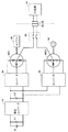
図1は、この発明の実施の形態による動力出力装置の概略ブロック図である。図1を参照して、この動力出力装置100は、バッテリBと、昇圧コンバータ10と、インバータ20,30と、モータジェネレータMG1,MG2と、リレー回路40と、コネクタ50と、制御装置60と、コンデンサC1,C2と、電源ラインPL1,PL2と、接地ラインSLと、U相ラインUL1,UL2と、V相ラインVL1,VL2と、W相ラインWL1,WL2と、ACラインACL1,ACL2と、電圧センサ70,72と、電流センサ80,82とを備える。
FIG. 1 is a schematic block diagram of a power output apparatus according to an embodiment of the present invention. Referring to FIG. 1,
この動力出力装置100は、たとえば、ハイブリッド自動車(Hybrid Vehicle)に搭載される。そして、モータジェネレータMG1は、エンジンによって駆動される発電機として動作し、かつ、エンジン始動を行ない得る電動機として動作するものとしてハイブリッド自動車に組み込まれ、モータジェネレータMG2は、ハイブリッド自動車の駆動輪を駆動する電動機としてハイブリッド自動車に組み込まれる。
This
モータジェネレータMG1,MG2は、たとえば、3相交流同期電動機からなり、それぞれ3相コイル12,14をステータコイルとして含む。そして、モータジェネレータMG1は、エンジン出力を用いて3相交流電圧を発生し、その発生した3相交流電圧をインバータ20へ出力する。また、モータジェネレータMG1は、インバータ20から受ける3相交流電圧によって駆動力を発生し、エンジンの始動を行なう。モータジェネレータMG2は、インバータ30から受ける3相交流電圧によって車両の駆動トルクを発生する。また、モータジェネレータMG2は、車両の回生制動時、3相交流電圧を発生してインバータ30へ出力する。
Motor generators MG1 and MG2 are made of, for example, a three-phase AC synchronous motor, and include three-
直流電源であるバッテリBは、たとえば、ニッケル水素やリチウムイオン等の二次電池からなる。バッテリBは、発生した直流電圧を昇圧コンバータ10へ出力し、また、昇圧コンバータ10から出力される直流電圧によって充電される。
The battery B, which is a direct current power source, is composed of, for example, a secondary battery such as nickel hydride or lithium ion. Battery B outputs the generated DC voltage to boost
昇圧コンバータ10は、リアクトルLと、npn型トランジスタQ1,Q2と、ダイオードD1,D2とを含む。リアクトルLは、電源ラインPL1に一端が接続され、npn型トランジスタQ1,Q2の接続点に他端が接続される。npn型トランジスタQ1,Q2は、たとえば、IGBT(Insulated Gate Bipolar Transistor)からなり、電源ラインPL2と接地ラインSLとの間に直列に接続され、制御装置60からの信号PWCをベースに受ける。そして、各npn型トランジスタQ1,Q2のコレクタ−エミッタ間には、エミッタ側からコレクタ側へ電流を流すようにダイオードD1,D2がそれぞれ接続される。
インバータ20は、U相アーム22、V相アーム24およびW相アーム26を含む。U相アーム22、V相アーム24およびW相アーム26は、電源ラインPL2と接地ラインSLとの間に並列に接続される。U相アーム22は、直列に接続されたnpn型トランジスタQ11,Q12からなり、V相アーム24は、直列に接続されたnpn型トランジスタQ13,Q14からなり、W相アーム26は、直列に接続されたnpn型トランジスタQ15,Q16からなる。各npn型トランジスタQ11〜Q16は、たとえばIGBTからなる。各npn型トランジスタQ11〜Q16のコレクタ−エミッタ間には、エミッタ側からコレクタ側へ電流を流すダイオードD11〜D16がそれぞれ接続される。そして、各相アームにおける各npn型トランジスタの接続点は、U,V,W各相ラインUL1,VL1,WL1を介してモータジェネレータMG1の各相コイルの中性点N1と異なるコイル端にそれぞれ接続される。
インバータ30は、U相アーム32、V相アーム34およびW相アーム36を含む。U相アーム32、V相アーム34およびW相アーム36は、電源ラインPL2と接地ラインSLとの間に並列に接続される。U相アーム32は、直列に接続されたnpn型トランジスタQ21,Q22からなり、V相アーム34は、直列に接続されたnpn型トランジスタQ23,Q24からなり、W相アーム36は、直列に接続されたnpn型トランジスタQ25,Q26からなる。各npn型トランジスタQ21〜Q26も、たとえばIGBTからなる。各npn型トランジスタQ21〜Q26のコレクタ−エミッタ間には、エミッタ側からコレクタ側へ電流を流すダイオードD21〜D26がそれぞれ接続される。そして、インバータ30においても、各相アームにおける各npn型トランジスタの接続点は、U,V,W各相ラインUL2,VL2,WL2を介してモータジェネレータMG2の各相コイルの中性点N2と異なるコイル端にそれぞれ接続される。
コンデンサC1は、電源ラインPL1と接地ラインSLとの間に接続され、電圧変動に起因するバッテリBおよび昇圧コンバータ10への影響を低減する。コンデンサC2は、電源ラインPL2と接地ラインSLとの間に接続され、電圧変動に起因するインバータ20,30および昇圧コンバータ10への影響を低減する。
Capacitor C1 is connected between power supply line PL1 and ground line SL, and reduces the influence on battery B and boost
昇圧コンバータ10は、バッテリBから電源ラインPL1を介して供給される直流電圧を昇圧して電源ラインPL2へ出力する。より具体的には、昇圧コンバータ10は、制御装置60からの信号PWCに基づいて、npn型トランジスタQ2のスイッチング動作に応じて流れる電流をリアクトルLに磁場エネルギーとして蓄積することによってバッテリBからの直流電圧を昇圧し、その昇圧した昇圧電圧をnpn型トランジスタQ2がオフされたタイミングに同期してダイオードD1を介して電源ラインPL2へ出力する。また、昇圧コンバータ10は、制御装置60からの信号PWCに基づいて、電源ラインPL2を介してインバータ20および/または30から受ける直流電圧をバッテリBの電圧レベルに降圧してバッテリBを充電する。
インバータ20は、制御装置60からの信号PWM1に基づいて、電源ラインPL2から供給される直流電圧を3相交流電圧に変換してモータジェネレータMG1を駆動する。これにより、モータジェネレータMG1は、トルク指令値TR1によって指定されたトルクを発生するように駆動される。また、インバータ20は、エンジンからの出力を受けてモータジェネレータMG1が発電した3相交流電圧を制御装置60からの信号PWM1に基づいて直流電圧に変換し、その変換した直流電圧を電源ラインPL2へ出力する。
インバータ30は、制御装置60からの信号PWM2に基づいて、電源ラインPL2から供給される直流電圧を3相交流電圧に変換してモータジェネレータMG2を駆動する。これにより、モータジェネレータMG2は、トルク指令値TR2によって指定されたトルクを発生するように駆動される。また、インバータ30は、動力出力装置100が搭載されたハイブリッド自動車の回生制動時、駆動軸からの回転力を受けてモータジェネレータMG2が発電した3相交流電圧を制御装置60からの信号PWM2に基づいて直流電圧に変換し、その変換した直流電圧を電源ラインPL2へ出力する。なお、ここで言う回生制動とは、ハイブリッド自動車を運転するドライバーによるフットブレーキ操作があった場合の回生発電を伴なう制動や、フットブレーキを操作しないものの、走行中にアクセルペダルをオフすることで回生発電をさせながら車両を減速(または加速の中止)させることを含む。
リレー回路40は、リレーRY1,RY2を含む。リレーRY1,RY2は、たとえば、機械的な接点リレーからなるが、半導体リレーであってもよい。リレーRY1は、ACラインACL1とコネクタ50との間に設けられ、制御装置60からの制御信号CNTLに応じてオン/オフされる。リレーRY2は、ACラインACL2とコネクタ50との間に設けられ、制御装置60からの制御信号CNTLに応じてオン/オフされる。
このリレー回路40は、制御装置60からの制御信号CNTLに応じて、ACラインACL1,ACL2とコネクタ50との接続/切離しを行なう。すなわち、リレー回路40は、制御装置60からH(論理ハイ)レベルの制御信号CNTLを受けると、ACラインACL1,ACL2をコネクタ50と電気的に接続し、制御装置60からL(論理ロー)レベルの制御信号CNTLを受けると、ACラインACL1,ACL2をコネクタ50から電気的に切離す。
コネクタ50は、モータジェネレータMG1,MG2の中性点N1,N2間に生じる交流電圧Vacを外部負荷へ出力するための出力端子であり、電気機器の電源用コンセントや家庭の非常用電源のコンセントなどが接続される。
電圧センサ70は、バッテリBのバッテリ電圧Vbを検出し、その検出したバッテリ電圧Vbを制御装置60へ出力する。電圧センサ72は、コンデンサC2の両端の電圧、すなわち、昇圧コンバータ10の出力電圧Vdc(インバータ20,30の入力電圧に相当する。以下同じ。)を検出し、その検出した電圧Vdcを制御装置60へ出力する。
電流センサ80は、モータジェネレータMG1に流れるモータ電流MCRT1を検出し、その検出したモータ電流MCRT1を制御装置60へ出力する。電流センサ82は、モータジェネレータMG2に流れるモータ電流MCRT2を検出し、その検出したモータ電流MCRT2を制御装置60へ出力する。
制御装置60は、外部に設けられるECU(Electronic Control Unit)から出力されたモータジェネレータMG1,MG2のトルク指令値TR1,TR2およびモータ回転数MRN1,MRN2、電圧センサ70からのバッテリ電圧Vb、ならびに電圧センサ72からの電圧Vdcに基づいて、昇圧コンバータ10を駆動するための信号PWCを生成し、その生成した信号PWCを昇圧コンバータ10へ出力する。
また、制御装置60は、電圧VdcならびにモータジェネレータMG1のモータ電流MCRT1およびトルク指令値TR1に基づいて、モータジェネレータMG1を駆動するための信号PWM1を生成し、その生成した信号PWM1をインバータ20へ出力する。さらに、制御装置60は、電圧VdcならびにモータジェネレータMG2のモータ電流MCRT2およびトルク指令値TR2に基づいて、モータジェネレータMG2を駆動するための信号PWM2を生成し、その生成した信号PWM2をインバータ30へ出力する。
ここで、制御装置60は、イグニッションスイッチ(またはイグニッションキー)からの信号IGおよびECUからの信号ACに基づいて、モータジェネレータMG1,MG2の中性点N1,N2間に商用電源用の交流電圧Vacを生成するようにインバータ20,30を制御するための信号PWM1,PWM2を生成する。なお、信号IG,ACについては、後ほど説明する。
Here, based on signal IG from the ignition switch (or ignition key) and signal AC from ECU,
さらに、制御装置60は、バッテリBのSOC(State Of Charge)およびエンジン出力を受けて発電するモータジェネレータMG1の発電状態に基づいて、モータジェネレータMG1,MG2の中性点N1,N2間に生成する商用電源用の交流電圧Vacを外部負荷へ安定的に出力可能か否かを判断し、交流電圧Vacを安定的に出力可能と判断したときは、Hレベルの制御信号CNTLをリレー回路40へ出力する。一方、制御装置60は、交流電圧Vacを安定的に出力可能でないと判断したときは、Lレベルの制御信号CNTLをリレー回路40へ出力し、モータジェネレータMG1,MG2の中性点N1,N2間に電圧差を発生させないためのAC出力停止処理を行なう。
Further,
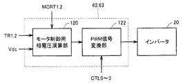
図2は、図1に示した制御装置60の機能ブロック図である。図2を参照して、制御装置60は、コンバータ制御部61と、第1および第2のインバータ制御部62,63と、AC出力制御部64とを含む。コンバータ制御部61は、バッテリ電圧Vb、電圧Vdc、トルク指令値TR1,TR2、およびモータ回転数MRN1,MRN2に基づいて昇圧コンバータ10のnpn型トランジスタQ1,Q2をオン/オフするための信号PWCを生成し、その生成した信号PWCを昇圧コンバータ10へ出力する。
FIG. 2 is a functional block diagram of the
第1のインバータ制御部62は、モータジェネレータMG1のトルク指令値TR1およびモータ電流MCRT1ならびに電圧Vdcに基づいてインバータ20のnpn型トランジスタQ11〜Q16をオン/オフするための信号PWM1を生成し、その生成した信号PWM1をインバータ20へ出力する。
First
第2のインバータ制御部63は、モータジェネレータMG2のトルク指令値TR2およびモータ電流MCRT2ならびに電圧Vdcに基づいてインバータ30のnpn型トランジスタQ21〜Q26をオン/オフするための信号PWM2を生成し、その生成した信号PWM2をインバータ30へ出力する。
Second
AC出力制御部64は、信号IG,ACに応じて、トルク指令値TR1,TR2およびモータ回転数MRN1,MRN2に基づいてモータジェネレータMG1,MG2の駆動状態を判定する。ここで、信号ACは、たとえば、AC出力スイッチの操作に応じて論理レベルが変化する信号であり、Hレベルの信号ACは、商用電源用の交流電圧Vacの出力を要求する信号であり、Lレベルの信号ACは、交流電圧Vacの出力を要求しない信号である。また、信号IGは、イグニッションスイッチの操作に応じて論理レベルが変化する信号であり、Hレベルの信号IGは、動力出力装置100が搭載されたハイブリッド自動車が起動されたことを意味する信号であり、Lレベルの信号IGは、ハイブリッド自動車が停止されたことを意味する信号である。
AC
そして、AC出力制御部64は、モータジェネレータMG1,MG2の駆動状態に応じて交流電圧Vacを発生するために、制御信号CTL0〜CTL3を生成して第1および第2のインバータ制御部62,63へ出力する。
AC
より具体的には、AC出力制御部64は、Hレベルの信号IGを受けた後にLレベルの信号ACを受けると、交流電圧Vacの発生は要求されていないと判定し、制御信号CTL0を生成して第1および第2のインバータ制御部62,63へ出力する。
More specifically, when AC
また、AC出力制御部64は、Lレベルの信号IGを受け、その後、Hレベルの信号ACを受けると、ハイブリッド自動車の停止時(モータジェネレータMG1,MG2は非駆動状態)に交流電圧Vacの発生が要求されたと判定し、制御信号CTL1を生成して第1および第2のインバータ制御部62,63へ出力する。
AC
さらに、AC出力制御部64は、Hレベルの信号IGを受け、その後、Hレベルの信号ACを受けると、トルク指令値TR1,TR2およびモータ回転数MRN1,MRN2に基づいて、モータジェネレータMG1,MG2が回生モードにあるか力行モードにあるかを判定する。すなわち、モータ回転数を横軸にとり、トルク指令値を縦軸にとった直交座標において、モータ回転数MRN1とトルク指令値TR1との関係が第1象限または第2象限に存在するとき、モータジェネレータMG1は力行モードにあり、モータ回転数MRN1とトルク指令値TR1との関係が第3象限または第4象限に存在するとき、モータジェネレータMG1は、回生モードにある。したがって、AC出力制御部64は、モータ回転数MRN1とトルク指令値TR1との関係が第1象限から第4象限のいずれに存在するかによってモータジェネレータMG1が力行モードにあるか回生モードにあるかを判定する。また、AC出力制御部64は、同様に、モータ回転数MRN2とトルク指令値TR2との関係が第1象限から第4象限のいずれに存在するかによってモータジェネレータMG2が力行モードにあるか回生モードにあるかを判定する。
Further, AC
そして、AC出力制御部64は、モータジェネレータMG1(またはMG2)が力行モードにあると判定したとき、モータジェネレータMG1(またはMG2)の力行モード時に交流電圧Vacの発生が要求されたと判定し、制御信号CTL2を生成して第1および第2のインバータ制御部62,63へ出力する。
Then, when AC
一方、AC出力制御部64は、モータジェネレータMG1(またはMG2)が回生モードにあると判定したとき、モータジェネレータMG1(またはMG2)の回生モード時に交流電圧Vacの発生が要求されたと判定し、制御信号CTL3を生成して第1および第2のインバータ制御部62,63へ出力する。
On the other hand, when AC
また、AC出力制御部64は、コネクタ50に接続された外部負荷へ交流電圧Vacを安定的に出力可能か否かを判断し、交流電圧Vacを安定的に出力可能と判断したときは、制御信号CNTLをHレベルでリレー回路40へ出力し、交流電圧Vacを安定的に出力可能でないと判断したときは、制御信号CNTLをLレベルでリレー回路40へ出力する。
Further, the AC
図3は、図2に示したコンバータ制御部61の機能ブロック図である。図3を参照して、コンバータ制御部61は、インバータ入力電圧指令演算部112と、フィードバック電圧指令演算部114と、デューティー比演算部116と、PWM信号変換部118とからなる。
FIG. 3 is a functional block diagram of
インバータ入力電圧指令演算部112は、トルク指令値TR1,TR2およびモータ回転数MRN1,MRN2に基づいてインバータ入力電圧の最適値(目標値)、すなわち電圧指令Vdc_comを演算し、その演算した電圧指令Vdc_comをフィードバック電圧指令演算部114へ出力する。
The inverter input voltage
フィードバック電圧指令演算部114は、電圧センサ72によって検出される昇圧コンバータ10の出力電圧Vdcと、インバータ入力電圧指令演算部112からの電圧指令Vdc_comとに基づいて、出力電圧Vdcを電圧指令Vdc_comに制御するためのフィードバック電圧指令Vdc_com_fbを演算し、その演算したフィードバック電圧指令Vdc_com_fbをデューティー比演算部116へ出力する。
Feedback voltage
デューティー比演算部116は、電圧センサ70からのバッテリ電圧Vbと、フィードバック電圧指令演算部114からのフィードバック電圧指令Vdc_com_fbとに基づいて、昇圧コンバータ10の出力電圧Vdcを電圧指令Vdc_comに制御するためのデューティー比を演算し、その演算したデューティー比をPWM信号変換部118へ出力する。
Duty
PWM信号変換部118は、デューティー比演算部116から受けたデューティー比に基づいて昇圧コンバータ10のnpn型トランジスタQ1,Q2をオン/オフするためのPWM(Pulse Width Modulation)信号を生成し、その生成したPWM信号を信号PWCとして昇圧コンバータ10のnpn型トランジスタQ1,Q2へ出力する。
PWM
なお、昇圧コンバータ10の下アームのnpn型トランジスタQ2のオンデューティーを大きくすることによりリアクトルLにおける電力蓄積が大きくなるため、より高電圧の出力を得ることができる。一方、上アームのnpn型トランジスタQ1のオンデューティーを大きくすることにより電源ラインPL2の電圧が下がる。そこで、npn型トランジスタQ1,Q2のデューティー比を制御することで、電源ラインPL2の電圧をバッテリBの出力電圧以上の任意の電圧に制御することができる。
Note that increasing the on-duty of npn transistor Q2 in the lower arm of
図4は、図2に示した第1および第2のインバータ制御部62,63の機能ブロック図である。図4を参照して、第1および第2のインバータ制御部62,63の各々は、モータ制御用相電圧演算部120と、PWM信号変換部122とからなる。
FIG. 4 is a functional block diagram of first and second
モータ制御用相電圧演算部120は、インバータ20,30の入力電圧Vdcを電圧センサ72から受け、モータジェネレータMG1(またはMG2)の各相に流れるモータ電流MCRT1(またはMCRT2)を電流センサ80(または82)から受け、トルク指令値TR1(またはTR2)をECUから受ける。そして、モータ制御用相電圧演算部120は、これらの入力値に基づいて、モータジェネレータMG1(またはMG2)の各相コイルに印加する電圧を演算し、その演算した各相コイル電圧をPWM信号変換部122へ出力する。
Motor control phase
PWM信号変換部122は、AC出力制御部64から制御信号CTL0を受けると、モータ制御用相電圧演算部120から受ける各相コイル電圧指令に基づいて、実際にインバータ20(または30)の各npn型トランジスタQ11〜Q16(またはQ21〜Q26)をオン/オフする信号PWM1_0(信号PWM1の一種)(またはPWM2_0(信号PWM2の一種))を生成し、その生成した信号PWM1_0(またはPWM2_0)をインバータ20(または30)の各npn型トランジスタQ11〜Q16(またはQ21〜Q26)へ出力する。
When
このようにして、各npn型トランジスタQ11〜Q16(またはQ21〜Q26)がスイッチング制御され、モータジェネレータMG1(またはMG2)が指令されたトルクを出力するようにモータジェネレータMG1(またはMG2)の各相に流す電流が制御される。その結果、トルク指令値TR1(またはTR2)に応じたモータトルクが出力される。 In this way, each npn transistor Q11 to Q16 (or Q21 to Q26) is subjected to switching control, and each phase of motor generator MG1 (or MG2) is output so that motor generator MG1 (or MG2) outputs a commanded torque. The current flowing through is controlled. As a result, a motor torque corresponding to the torque command value TR1 (or TR2) is output.
また、PWM信号変換部122は、AC出力制御部64から制御信号CTL1を受けると、モータ制御用相電圧演算部120から受ける各相コイル電圧指令に基づいて、インバータ20(または30)のU相アーム22(または32)、V相アーム24(または34)およびW相アーム26(または36)に同位相の交流電流を流すようにnpn型トランジスタQ11〜Q16(またはQ21〜Q26)をオン/オフする信号PWM1_1(信号PWM1の一種)(またはPWM2_1(信号PWM2の一種))を生成し、その生成した信号PWM1_1(またはPWM2_1)をインバータ20(または30)のnpn型トランジスタQ11〜Q16(またはQ21〜Q26)へ出力する。
Further, when receiving the control signal CTL1 from the AC
さらに、PWM信号変換部122は、AC出力制御部64から制御信号CTL2を受けると、モータ制御用相電圧演算部120から受ける各相コイル電圧指令に基づいて、スイッチング制御するためのデューティーを商用交流周波数で変化させながらインバータ20(または30)の各npn型トランジスタQ11〜Q16(またはQ21〜Q26)をオン/オフする信号PWM1_2(信号PWM1の一種)(またはPWM2_2(信号PWM2の一種))を生成し、その生成した信号PWM1_2(またはPWM2_2)をインバータ20(または30)のnpn型トランジスタQ11〜Q16(またはQ21〜Q26)へ出力する。
Further, when receiving the control signal CTL2 from the AC
さらに、PWM信号変換部122は、AC出力制御部64から制御信号CTL3を受けると、モータ制御用相電圧演算部120から受ける各相コイル電圧指令に基づいて、モータジェネレータMG1(またはMG2)が商用交流周波数の交流電圧を発電するようにインバータ20(または30)の各npn型トランジスタQ11〜Q16(またはQ21〜Q26)をオン/オフする信号PWM1_3(信号PWM1の一種)(またはPWM2_3(信号PWM2の一種))を生成し、その生成した信号PWM1_3(またはPWM2_3)をインバータ20(または30)のnpn型トランジスタQ11〜Q16(またはQ21〜Q26)へ出力する。
Further, when PWM
次に、動力出力装置100において商用電源用の交流電圧Vacを発生する方法について説明する。まず、動力出力装置100におけるモータジェネレータMG1,MG2の非駆動状態時に交流電圧Vacを発生する方法について説明する。
Next, a method for generating an AC voltage Vac for commercial power in the
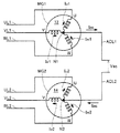
図5は、図1に示したモータジェネレータMG1,MG2の3相コイル12,14に流す交流電流のタイミングチャートであり、図6は、モータジェネレータMG1,MG2を流れる電流を示す図である。なお、図6では、モータジェネレータMG1の中性点N1からモータジェネレータMG2の中性点N2へ交流電流Iacが流される場合について示される。
FIG. 5 is a timing chart of AC currents flowing through the three-
図5を参照して、制御装置60は、商用交流周波数からなる互いに同位相の交流電流を3相コイル12の各相コイルに流すようにインバータ20のU相アーム22、V相アーム24およびW相アーム26をスイッチング制御し、3相コイル12の各相コイルに流す交流電流の位相を反転した互いに同位相の交流電流を3相コイル14の各相コイルに流すようにインバータ30のU相アーム32、V相アーム34およびW相アーム36をスイッチング制御する。
Referring to FIG. 5,
すなわち、交流電流Iu1,Iv1,Iw1;Iu2,Iv2,Iw2の1周期Tの前半においては、インバータ20において、npn型トランジスタQ11,Q13,Q15がスイッチング制御され、npn型トランジスタQ12,Q14,Q16はオフされる。また、インバータ30においては、npn型トランジスタQ21,Q23,Q25はオフされ、npn型トランジスタQ22,Q24,Q26がスイッチング制御される。
That is, in the first half of one cycle T of alternating currents Iu1, Iv1, Iw1; Turned off. In
また、1周期Tの後半においては、インバータ20において、npn型トランジスタQ11,Q13,Q15はオフされ、npn型トランジスタQ12,Q14,Q16がスイッチング制御される。また、インバータ30においては、npn型トランジスタQ21,Q23,Q25がスイッチング制御され、npn型トランジスタQ22,Q24,Q26はオフされる。
In the second half of one cycle T, in the
これにより、3相コイル12の中性点N1に商用交流周波数を有する交流電圧が発生し、3相コイル12の中性点N1に発生する交流電圧の位相を反転した交流電圧が3相コイル14の中性点N2に発生する。そして、コネクタ50に外部負荷が接続され、かつ、リレー回路40がオンされると、1周期Tの前半の半周期において、図6に示されるように、npn型トランジスタQ11,Q13,Q15(図示せず)からU,V,W各相ラインVL1,VL1,WL1、3相コイル12の各相コイル、中性点N1、ACラインACL1、外部負荷、ACラインACL2、中性点N2、3相コイル14の各相コイル、およびU,V,W各相ラインVL2,VL2,WL2を介してnpn型トランジスタQ22,Q24,Q26(図示せず)へ電流が流れる。また、1周期Tの後半の半周期においては、npn型トランジスタQ21,Q23,Q25からU,V,W各相ラインVL2,VL2,WL2、3相コイル14の各相コイル、中性点N2、ACラインACL2、外部負荷、ACラインACL1、中性点N1、3相コイル12の各相コイル、およびU,V,W各相ラインVL1,VL1,WL1を介してnpn型トランジスタQ12,Q14,Q16へ電流が流れる。
Thereby, an AC voltage having a commercial AC frequency is generated at the neutral point N1 of the three-
このように、1周期Tの半周期毎に向きが切り替えられる電流すなわち交流電流Iacが3相コイル12の中性点N1と3相コイル14の中性点N2との間で流れる。また、電流の向きが切り替えられる周波数は、商用交流周波数である。そして、中性点N1に発生する交流電圧と、中性点N2に発生し、かつ、中性点N1に発生する交流電圧の位相が反転された交流電圧との電圧差が商用交流電圧となるように、スイッチング制御が行なわれるnpn型トランジスタのデューティーを制御することによって、中性点N1,N2間に商用電源用の交流電圧Vacを発生させることができる。
In this way, a current whose direction is switched every half cycle of one cycle T, that is, an alternating current Iac flows between the neutral point N1 of the three-
なお、上記の場合、3相コイル12,14には、同位相の交流電流が流され、モータジェネレータMG1,MG2は、駆動制御されていない。したがって、モータジェネレータMG1,MG2は、トルクを発生しない。
In the above case, an alternating current having the same phase is passed through the three-
また、上記においては、インバータ20のnpn型トランジスタQ11,Q13,Q15の全ておよびnpn型トランジスタQ12,Q14,Q16の全てをオン/オフし、インバータ30のnpn型トランジスタQ21,Q23,Q25の全ておよびnpn型トランジスタQ22,Q24,Q26の全てをオン/オフして各3相コイル12,14において同位相の交流電流を流すものとしたが、この発明においては、これに限らず、インバータ20のnpn型トランジスタQ11,Q13,Q15の少なくとも1つおよびnpn型トランジスタQ12,Q14,Q16の少なくとも1つをオン/オフし、インバータ30のnpn型トランジスタQ21,Q23,Q25の少なくとも1つおよびnpn型トランジスタQ22,Q24,Q26の少なくとも1つをオン/オフして各3相コイル12,14において同位相の交流電流を流すようにしてもよい。
In the above, all of npn transistors Q11, Q13, Q15 of
次に、動力出力装置100におけるモータジェネレータMG1,MG2の駆動状態時に交流電圧Vacを発生する方法について説明する。この場合、モータジェネレータMG1,MG2が発生する駆動トルクは、力行トルクであっても回生トルクであってもよい。すなわち、たとえば、動力出力装置100が搭載されたハイブリッド自動車の停車中であって、エンジンと連結されたモータジェネレータMG1を回生駆動し、車両の駆動軸と連結されたモータジェネレータMG2を反力制御(力行駆動)しているときや、動力出力装置100が搭載されたハイブリッド自動車の走行中であって、モータジェネレータMG1を回生駆動し、モータジェネレータMG2を力行駆動しているときに、交流電圧Vacを発生する。
Next, a method of generating AC voltage Vac when motor generators MG1 and MG2 are driven in
図7は、デューティーの総和および商用電源用の交流電圧Vacの波形図である。図7を参照して、曲線k1は、インバータ20のスイッチング制御におけるデューティーの総和の変化を示し、曲線k2は、インバータ30のスイッチング制御におけるデューティーの総和の変化を示す。ここで、デューティーの総和とは、各インバータにおける上アームのオンデューティーから下アームのオンデューティーを減算したものである。
FIG. 7 is a waveform diagram of the total duty and the AC voltage Vac for commercial power. Referring to FIG. 7, a curve k <b> 1 shows a change in the total duty in the switching control of
すなわち、インバータ20(30)の上アームを構成するnpn型トランジスタQ11,Q13,Q15(インバータ30にあっては、npn型トランジスタQ21,Q23,Q25)のオンデューティーと、インバータ20(30)の下アームを構成するnpn型トランジスタQ12,Q14,Q16(インバータ30にあっては、npn型トランジスタQ22,Q24,Q26)のオンデューティーとの大小関係によって、中性点N1(インバータ30にあっては中性点N2)の電位はインバータ20(30)の入力電圧Vdcの中間電位Vdc/2を中心にして上下するので、インバータ20(30)におけるデューティーの総和が正のときは、中性点N1(N2)の電位が電位Vdc/2よりも高くなることを示し、インバータ20(30)におけるデューティーの総和が負のときは、中性点N1(N2)の電位が電位Vdc/2よりも低くなることを示す。
That is, the on-duty of npn transistors Q11, Q13, Q15 (in the case of
ここで、図7において、デューティーの総和が変化する周波数は、商用交流周波数である。 Here, in FIG. 7, the frequency at which the sum of the duty changes is a commercial AC frequency.
この動力出力装置100においては、制御装置60は、インバータ20のデューティーの総和を曲線k1に従って商用交流周波数で周期的に変化させ、インバータ30のデューティーの総和を曲線k2に従って商用交流周波数で周期的に変化させる。ここで、インバータ30のデューティーの総和は、インバータ20のデューティーの総和が変化する位相を反転した位相で周期的に変えられる。
In
そうすると、時刻t0においては、インバータ20,30の双方においてデューティーの総和は0であるので(すなわち、上アームのオンデューティーは、下アームのオンデューティーと等しい。)、中性点N1,N2の電位は、いずれも電位Vdc/2であり、中性点N1,N2間に発生する交流電圧Vacは0Vである。
Then, at time t0, since the sum of the duties in both
時刻t0〜t1においては、中性点N1の電位は、電位Vdc/2よりも高くなり、中性点N2の電位は、電位Vdc/2よりも低くなるので、中性点N1,N2間に発生する交流電圧Vacは上昇し、時刻t1において最大となる。 At time t0 to t1, the potential at the neutral point N1 is higher than the potential Vdc / 2, and the potential at the neutral point N2 is lower than the potential Vdc / 2. Therefore, between the neutral points N1 and N2. The generated AC voltage Vac rises and becomes maximum at time t1.
その後、時刻t1〜t2においては、中性点N1の電位は、最大値よりも徐々に低くなり、中性点N2の電位は、最小値よりも徐々に高くなるので、中性点N1,N2間に発生する交流電圧Vacは低下し、時刻t2において0Vとなる。 Thereafter, from time t1 to t2, the potential at the neutral point N1 is gradually lower than the maximum value, and the potential at the neutral point N2 is gradually higher than the minimum value. Therefore, the neutral points N1, N2 The AC voltage Vac generated in the meantime drops to 0 V at time t2.
さらに、時刻t2〜t3においては、中性点N1の電位は、電位Vdc/2よりも低くなり、中性点N2の電位は、電位Vdc/2よりも高くなるので、中性点N1,N2間に発生する交流電圧Vacは、時刻t0〜t2までの電圧と極性が反転して負側に上昇し、時刻t3において負側に最大となる。その後、時刻t3〜t4においては、中性点N1の電位は、最小値よりも徐々に高くなり、中性点N2の電位は、最大値よりも徐々に低くなるので、中性点N1,N2間に発生する交流電圧Vacは負側の最大値から低下し、時刻t4において0Vとなる。 Further, at times t2 to t3, the potential at the neutral point N1 is lower than the potential Vdc / 2, and the potential at the neutral point N2 is higher than the potential Vdc / 2. Therefore, the neutral points N1, N2 The AC voltage Vac generated in the meantime reverses the polarity of the voltage from time t0 to t2 and rises to the negative side, and reaches the negative side at time t3. Thereafter, from time t3 to t4, the potential at the neutral point N1 gradually becomes higher than the minimum value, and the potential at the neutral point N2 becomes gradually lower than the maximum value. Therefore, the neutral points N1, N2 The AC voltage Vac generated in the meantime drops from the negative maximum value and becomes 0 V at time t4.
この場合、時刻t0〜t2までの間、インバータ20においては、上アームのオンデューティーは、下アームのオンデューティーよりも大きいので、インバータ20の上アームから3相コイル12の中性点N1に流れ込む電流は、中性点N1からインバータ20の下アームへ流れる電流よりも多くなる。一方、インバータ30においては、下アームのオンデューティーは、上アームのオンデューティーよりも大きいので、3相コイル14の中性点N2からインバータ30の下アームへ流れる電流は、インバータ30の上アームから中性点N2に流れ込む電流よりも多くなる。そして、曲線k1,k2によって示されるように、インバータ20,30において、上アームのオンデューティーと下アームのオンデューティーとの差は、絶対値が同じであり、極性が反対である。
In this case, since the on-duty of the upper arm is larger than the on-duty of the lower arm in the
そうすると、コネクタ50に外部負荷が接続され、かつ、リレー回路40がオンしている場合、3相コイル12において、インバータ20の上アームから中性点N1に流れ込んだ電流のうち、中性点N1からインバータ20の下アームへ流れ込むことができない余った電流が、中性点N1からACラインACL1、外部負荷およびACラインACL2を介して3相コイル14の中性点N2へ流れ、中性点N2からインバータ30の下アームへ流れる。
Then, when an external load is connected to the
また、時刻t2〜t4までの間、インバータ30においては、上アームのオンデューティーは、下アームのオンデューティーよりも大きいので、インバータ30の上アームから3相コイル14の中性点N2に流れ込む電流は、中性点N2からインバータ30の下アームへ流れる電流よりも多くなる。一方、インバータ20においては、下アームのオンデューティーは、上アームのオンデューティーよりも大きいので、3相コイル12の中性点N1からインバータ20の下アームへ流れる電流は、インバータ20の上アームから中性点N1に流れ込む電流よりも多くなる。
Further, since the on-duty of the upper arm is larger than the on-duty of the lower arm in the
そうすると、3相コイル14において、インバータ30の上アームから中性点N2に流れ込んだ電流のうち、中性点N2からインバータ30の下アームへ流れ込むことができない余った電流が、中性点N2からACラインACL2、外部負荷およびACラインACL1を介して3相コイル12の中性点N1へ流れ、中性点N1からインバータ20の下アームへ流れる。
Then, in the three-
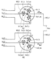
図8は、モータジェネレータMG1,MG2を流れる電流を示す図である。なお、この図8では、モータジェネレータMG1の中性点N1からモータジェネレータMG2の中性点N2へ交流電流Iacが流される場合について示される。 FIG. 8 shows a current flowing through motor generators MG1 and MG2. FIG. 8 shows a case where AC current Iac flows from neutral point N1 of motor generator MG1 to neutral point N2 of motor generator MG2.
図8を参照して、U,V,W各相ラインUL1,VL1,WL1に接続されるインバータ20(図示せず)は、制御装置60からの信号PWM1に基づいてスイッチング動作を行ない、電流成分Iu1_t,Iu1_acからなるU相電流をモータジェネレータMG1のU相コイルに流し、電流成分Iv1_t,Iv1_acからなるV相電流をモータジェネレータMG1のV相コイルに流し、電流成分Iw1_t,Iw1_acからなるW相電流をモータジェネレータMG1のW相コイルに流す。
Referring to FIG. 8, inverter 20 (not shown) connected to each of U, V, W phase lines UL1, VL1, WL1 performs a switching operation based on a signal PWM1 from
また、U,V,W各相ラインUL2,VL2,WL2に接続されるインバータ30(図示せず)は、制御装置60からの信号PWM2に基づいてスイッチング動作を行ない、電流成分Iu2_t,Iu2_acからなるU相電流をモータジェネレータMG2のU相コイルに流し、電流成分Iv2_t,Iv2_acからなるV相電流をモータジェネレータMG2のV相コイルに流し、電流成分Iw2_t,Iw2_acからなるW相電流をモータジェネレータMG2のW相コイルに流す。
Further, an inverter 30 (not shown) connected to the U, V, W phase lines UL2, VL2, WL2 performs a switching operation based on a signal PWM2 from the
ここで、電流成分Iu1_t,Iv1_t,Iw1_tは、モータジェネレータMG1にトルクを発生させるための電流であり、電流成分Iu2_t,Iv2_t,Iw2_tは、モータジェネレータMG2にトルクを発生させるための電流である。また、電流成分Iu1_ac,Iv1_ac,Iw1_acは、インバータ20において、上アームのオンデューティーが下アームのオンデューティーよりも大きくなるように制御されることによってインバータ20の上アームから3相コイル12の中性点N1に流れ込む電流であり、電流成分Iu2_ac,Iv2_ac,Iw2_acは、インバータ30において、下アームのオンデューティーが上アームのオンデューティーよりも大きくなるように制御されることによって3相コイル14の中性点N2からインバータ30の下アームへ流れ込む電流である。電流成分Iu1_ac,Iv1_ac,Iw1_ac,Iu2_ac,Iv2_ac,Iw2_acは、互いに同じ大きさであり、モータジェネレータMG1,MG2のトルクに寄与しない。そして、電流成分Iu1_ac,Iv1_ac,Iw1_acの合計値および電流成分Iu2_ac,Iv2_ac,Iw2_acの合計値の各々が交流電流Iacに相当する。
Here, current components Iu1_t, Iv1_t, and Iw1_t are currents for generating torque in motor generator MG1, and current components Iu2_t, Iv2_t, and Iw2_t are currents for generating torque in motor generator MG2. Further, the current components Iu1_ac, Iv1_ac, Iw1_ac are neutralized from the upper arm of the
このように、インバータ20,30は、モータジェネレータMG1,MG2を駆動制御しつつ、モータジェネレータMG1,MG2の中性点N1,N2間に交流電圧Vacを発生させることができる。
Thus,
最後に、モータジェネレータMG1が回生モードにあり、モータジェネレータMG2が非駆動状態のときに商用電源用の交流電圧Vacを発生させる方法について説明する。 Finally, a method for generating AC voltage Vac for commercial power supply when motor generator MG1 is in the regeneration mode and motor generator MG2 is in the non-driven state will be described.
図9は、交流電流のタイミングチャートである。図9を参照して、インバータ20は、モータジェネレータMG1を回生モードで駆動する。したがって、モータジェネレータMG1は、発生した回生電流IREGをインバータ20に供給する。そして、インバータ30は、回生電流IREGの位相を反転させた互いに同相の交流電流Iu2,Iv2,Iw2をそれぞれ3相コイル14のU相コイル、V相コイルおよびW相コイルに流す。
FIG. 9 is a timing chart of the alternating current. Referring to FIG. 9,
ここで、回生電流IREGおよび交流電流Iu2,Iv2,Iw2の周波数が商用交流周波数になり、かつ、3相コイル12,14の中性点N1,N2間の電圧差が商用交流電圧となるようにインバータ20,30を制御することによって、中性点N1,N2間に商用電源用の交流電圧Vacを発生させることができる。
Here, the frequency of the regenerative current IREG and the alternating currents Iu2, Iv2, Iw2 is the commercial AC frequency, and the voltage difference between the neutral points N1, N2 of the three-
なお、インバータ30は、上述のように、互いに同相の交流電流Iu2,Iv2,Iw2をそれぞれ3相コイル14のU相コイル、V相コイルおよびW相コイルに流すだけで、モータジェネレータMG2の駆動制御を行なわない。したがって、モータジェネレータMG2は、トルクを発生しない。
As described above,
なお、上記においては、インバータ30のnpn型トランジスタQ21,Q23,Q25の全ておよびnpn型トランジスタQ22,Q24,Q26の全てをオン/オフして3相コイル14の各相コイルにおいて同位相の交流電流を流すものとしたが、この発明においては、これに限らず、インバータ30のnpn型トランジスタQ21,Q23,Q25の少なくとも1つおよびnpn型トランジスタQ22,Q24,Q26の少なくとも1つをオン/オフさせてもよい。
In the above description, all of the npn transistors Q21, Q23, Q25 of the
上述した方法によって、この動力出力装置100は、交流電圧Vacを発生させることができるが、バッテリBのSOCが十分でなかったり、モータジェネレータMG1によって発電がなされていないときに、交流電圧Vacの外部負荷への出力が開始されると、交流電圧Vacを安定的に発生し得ない。そして、交流電圧Vacの発生によりバッテリBのSOC不足が発生すれば、交流電圧Vacの電圧低下が発生する。そこで、この動力出力装置100においては、上述したように、AC出力制御部64は、コネクタ50に接続された外部負荷へ交流電圧Vacを安定的に出力可能か否かを判断し、その判断結果に基づいて交流電圧Vacの出力可否を制御する。
The
図10は、図2に示したAC出力制御部64の交流電圧出力処理に係る動作のフローチャートである。図10を参照して、AC出力制御部64は、まず、商用電源用の交流電圧Vacの出力要求がなされたか否かを判断するため、ECUからの信号ACの論理レベルがHレベルであるか否かを判定する(ステップS2)。AC出力制御部64は、信号ACがLレベルであると判定すると(ステップS2でNO)、交流電圧Vacの出力要求はなされていないと判断し、処理が終了する。
FIG. 10 is a flowchart of the operation relating to the AC voltage output process of the AC
AC出力制御部64は、信号ACがHレベルであると判定すると(ステップS2でYES)、安定的な交流電圧Vacを出力可能か否かを判断するため、バッテリBのSOCおよびエンジン状態を確認する。すなわち、AC出力制御部64は、バッテリBのSOCを検出し、後述するようにエンジン温度Tに依存するしきい値Sth(T)をSOCが下回っているか否かを判定する(ステップS4)。
When AC
ステップS4において、バッテリBのSOCがしきい値Sth(T)を下回っていると判定されると(ステップS4においてYES)、モータジェネレータMG1に連結されたエンジンがモータジェネレータMG1によって始動され(ステップS6)、モータジェネレータMG1による発電が行なわれる(ステップS8)。一方、ステップS4において、バッテリBのSOCがしきい値Sth(T)を下回っていないと判定されると(ステップS4においてNO)、ステップS10へ処理が進む。 If it is determined in step S4 that the SOC of battery B is lower than threshold value Sth (T) (YES in step S4), the engine connected to motor generator MG1 is started by motor generator MG1 (step S6). ), Power is generated by motor generator MG1 (step S8). On the other hand, when it is determined in step S4 that the SOC of battery B is not lower than threshold value Sth (T) (NO in step S4), the process proceeds to step S10.
ここで、バッテリBのSOCのしきい値Sth(T)は、図11に示すように、エンジン温度Tに依存し、エンジン温度Tが低いほど大きな値となる。すなわち、エンジンは、モータジェネレータMG1によって始動され、低温状態では、オイル粘度の上昇によってクランキングの動力抵抗が大きくなるので、始動に際して大きなトルクが必要となる。したがって、エンジンを始動するためのトルク電流を多く必要とするエンジンの低温時においては、バッテリBのSOCに応じたエンジンの始動タイミングを早めるものである。 Here, the SOC threshold value Sth (T) of the battery B depends on the engine temperature T as shown in FIG. 11, and increases as the engine temperature T decreases. That is, the engine is started by the motor generator MG1, and in a low temperature state, the power resistance of cranking increases due to the increase in oil viscosity, so that a large torque is required for starting. Therefore, the engine start timing corresponding to the SOC of the battery B is advanced at a low temperature of the engine that requires a large torque current for starting the engine.
つまり、AC出力制御部64は、安定的な交流電圧Vacを出力可能か否かの判断に際して、バッテリBのSOCとエンジン温度Tに依存するしきい値Sth(T)との関係、すなわち、バッテリBのSOCとエンジンの状態(エンジン温度Tおよびエンジンによる発電状態)とを確認する。
That is, when determining whether or not the stable AC voltage Vac can be output, the AC
そして、AC出力制御部64は、バッテリBのSOCおよびエンジンの状態、ならびにインバータ20,30に入力される電圧Vdcが確保されているか否かに基づいて、交流電圧Vacの出力を許可するか否かを判断する(ステップS10)。すなわち、AC出力制御部64は、バッテリBのSOCがエンジン温度Tに依存するしきい値Sth(T)以上であって、かつ、安定的な交流電圧Vacを出力するのに十分な量であるか、さらに、交流電圧Vacを生成するのに必要な入力電圧Vdcが確保されているか、に基づいて交流電圧Vacの出力許可を判定する。
Then, AC
なお、バッテリBのSOCがしきい値Sth(T)を下回っており、モータジェネレータMG1による発電が行なわれる場合、AC出力制御部64は、バッテリBのSOCがしきい値Sth(T)よりも大きい他のしきい値を上回ってから交流電圧Vacの出力を許可するようにしてもよい。これにより、しきい値Sth(T)近傍でSOCが変動することによって交流電圧Vacの出力の許可/不許可が頻繁に切替わるのを防止できる。
When SOC of battery B is lower than threshold value Sth (T) and power generation is performed by motor generator MG1, AC
ステップS10において、交流電圧Vacの出力が許可されると(ステップS10においてYES)、インバータ20,30によってモータジェネレータMG1,MG2の中性点N1,N2間に交流電圧Vacが生成され、AC出力制御部64は、リレー回路40へHレベルの制御信号CNTLを出力する。これによって、コネクタ50に接続される外部負荷へ商用電源用の交流電圧Vacが出力される(ステップS12)。
When output of AC voltage Vac is permitted in step S10 (YES in step S10), AC voltage Vac is generated between neutral points N1 and N2 of motor generators MG1 and MG2 by
一方、ステップS10において、交流電圧Vacの出力が許可されないとき(ステップS10においてNO)、AC出力制御部64は、リレー回路40へLレベルの制御信号CNTLを出力する。さらに、制御装置60は、モータジェネレータMG1,MG2の中性点N1,N2間に交流電圧Vacが発生しないようにするため、インバータ20,30を同じスイッチングパターンで制御する。これにより、仮にリレー回路40に溶着などの不具合が発生しても、交流電圧Vacの出力が確実に停止される(ステップS14)。なお、動力出力装置100が搭載されたハイブリッド自動車が停止中であれば、モータジェネレータMG1,MG2の中性点N1,N2間に交流電圧Vacが発生しないようにするために、インバータ20,30のスイッチング動作を停止させてもよい。
On the other hand, when output of AC voltage Vac is not permitted in step S10 (NO in step S10), AC
交流電圧Vacの出力中、AC出力制御部64は、信号ACや異常検出などの情報に基づいて、交流電圧Vacの出力を停止するか否かを判定する(ステップS16)。AC出力制御部64は、交流電圧Vacの出力を停止しないと判定したときは(ステップS16においてNO)、コネクタ50に接続される外部負荷への交流電圧Vacの出力を継続する。
During the output of the AC voltage Vac, the AC
一方、AC出力スイッチが操作されて信号ACがLレベルとなったり、何らかの異常が検出されるなどして、AC出力制御部64が交流電圧Vacの出力を停止すると判定したときは(ステップS16においてYES)、ステップS14と同様の処理により、交流電圧Vacの出力が停止される(ステップS18)。
On the other hand, when the AC
以上のように、この発明の実施の形態による動力出力装置100によれば、モータジェネレータMG1,MG2に含まれる3相コイル12,14の中性点N1,N2の電位を制御することによって、中性点N1,N2間に商用電源用の交流電圧Vacを発生させることができる。
As described above, according to
そして、モータジェネレータMG1,MG2が非駆動状態のときに交流電圧Vacを発生させる場合、インバータ20によってモータジェネレータMG1の3相コイル12の各相コイルに流される同位相の交流電流、およびその交流電流の位相を反転した交流電流であって、かつ、インバータ30によってモータジェネレータMG2の3相コイル14の各相コイルに流される同位相の交流電流の周波数を選択することによって、交流電圧Vacの周波数を任意に設定できる。すなわち、動力出力装置100は、任意の周波数を有する交流電圧Vacを発生させることができる。
Then, when AC voltage Vac is generated when motor generators MG1 and MG2 are in a non-driving state, an AC current of the same phase that is passed through each phase coil of three-
また、この動力出力装置100は、モータジェネレータMG1,MG2が駆動状態のときに交流電圧Vacを発生させる場合は、インバータ20,30に含まれるnpn型トランジスタQ11〜16,Q21〜Q26をスイッチング制御するときのデューティーを変化させる周波数によって交流電圧Vacの周波数が決定される。したがって、npn型トランジスタQ11〜16,Q21〜Q26をスイッチング制御するときのデューティーを変化させる周波数を選択することによって交流電圧Vacの周波数を任意に設定できる。すなわち、動力出力装置100は、任意の周波数を有する交流電圧Vacを発生させることができる。
In addition, motive
さらに、この動力出力装置100は、モータジェネレータMG1が回生モードにあり、モータジェネレータMG2が非駆動状態のときに交流電圧Vacを発生させる場合は、インバータ30によってモータジェネレータMG2の3相コイル14の各相コイルに流される同位相の交流電流および回生電流IREGの周波数を選択することによって、交流電圧Vacの周波数を任意に設定できる。すなわち、動力出力装置100は、任意の周波数を有する交流電圧Vacを発生させることができる。
Further, in the
また、さらに、この動力出力装置100によれば、バッテリBのSOCに基づいて交流電圧Vacの外部負荷への出力を許可するか否かが決定されるので、交流電圧Vacを出力する前に交流電圧Vacを安定的に発生し得るか否かを判断できる。したがって、不安定な交流電圧Vacの出力が防止される。
Further, according to the
また、さらに、この動力出力装置100によれば、交流電圧Vacの外部負荷への出力が許可されていないとき、リレー回路40に含まれるリレーRY1,RY2がオフされるので、不安定な交流電圧Vacの出力を防止できる。さらに、中性点N1,N2間に電圧差が発生しないようにインバータ20,30が制御されるので、仮にリレー回路40に含まれるリレーRY1,RY2に溶着等の不具合が発生しても、不安定な交流電圧の出力を確実に防止できる。
Furthermore, according to this
また、さらに、この動力出力装置100は、モータジェネレータMG1,MG2を駆動するインバータ20,30を用いて交流電圧Vacを発生するので、交流電圧Vacを得るための専用のインバータを必要としない。また、さらに、2つのインバータ20,30で交流電圧Vacの出力を分担できる。
Further,
図12は、この発明による動力出力装置100をハイブリッド自動車に適用した場合の概略ブロック図である。図12を参照して、モータジェネレータMG1は、エンジン92に連結され、エンジン92を始動するとともに、エンジン92からの出力によって発電する。モータジェネレータMG2は、駆動輪94に連結され、駆動輪94を駆動するとともに、ハイブリッド自動車の回生制動時に発電する。
FIG. 12 is a schematic block diagram when the
そして、コネクタ50には、外部負荷であるAC負荷96のコンセント55が接続され、動力出力装置100は、コネクタ50およびコンセント55を介してAC負荷96に商用電源用の交流電圧Vacを供給する。これにより、AC負荷96は、動力出力装置100から交流電圧Vacの供給を受けて動作することができる。
The
このように、動力出力装置100が搭載されたこのハイブリッド自動車は、商用交流電源として利用できる。そして、このハイブリッド自動車は、交流電圧Vacを発生するための専用インバータを備えないので、車両の小型化や軽量化、低コスト化などを実現しつつ、商用交流電源としての付加価値を有する。
Thus, this hybrid vehicle equipped with the
なお、上記においては、動力出力装置100は、ハイブリッド自動車に搭載されると説明したが、この発明においては、これに限らず、動力出力装置100は、電気自動車(Electric Vehicle)および燃料電池自動車に搭載されてもよい。そして、この発明は、一般に2つのモータジェネレータを使用するものに適用可能である。また、動力出力装置100が電気自動車および燃料電池自動車に搭載される場合、モータジェネレータMG1,MG2は、電気自動車および燃料電池自動車の駆動輪に連結される。
In the above description, the
なお、上記において、3相コイル12,14は、それぞれ「第1および第2の3相コイル」を構成し、インバータ20,30は、それぞれ「第1および第2のインバータ」を構成する。また、第1および第2のインバータ制御部62,63は、それぞれ「第1および第2の制御部」を構成し、バッテリBは、「直流電源」を構成する。さらに、モータジェネレータMG1,MG2は、それぞれ「第1および第2のモータジェネレータ」を構成し、バッテリBのSOCのしきい値Sth(T)は、「第1の所定値」を構成する。
In the above description, the three-
今回開示された実施の形態は、すべての点で例示であって制限的なものではないと考えられるべきである。本発明の範囲は、上記した実施の形態の説明ではなくて特許請求の範囲によって示され、特許請求の範囲と均等の意味および範囲内でのすべての変更が含まれることが意図される。 The embodiment disclosed this time should be considered as illustrative in all points and not restrictive. The scope of the present invention is shown not by the above description of the embodiments but by the scope of claims for patent, and is intended to include meanings equivalent to the scope of claims for patent and all modifications within the scope.
10 昇圧コンバータ、12,14 3相コイル、20,30 インバータ、22,32 U相アーム、24,34 V相アーム、26,36 W相アーム、40 リレー回路、50,55 コネクタ、60 制御装置、61 コンバータ制御部、62,63 インバータ制御部、64 AC出力制御部、70,72 電圧センサ、80,82 電流センサ、92 エンジン、94 駆動輪、96 AC負荷、100 動力出力装置、112 インバータ入力電圧指令演算部、114 フィードバック電圧指令演算部、116 デューティー比演算部、118,122 PWM信号変換部、120 モータ制御用相電圧演算部、B バッテリ、C1,C2 コンデンサ、PL1,PL2 電源ライン、SL 接地ライン、L リアクトル、MG1,MG2 モータジェネレータ、N1,N2 中性点、UL1,UL2 U相ライン、VL1,VL2 V相ライン、WL1,WL2 W相ライン、ACL1,ACL2 ACライン、Q1,Q2,Q11〜Q16,Q21〜Q26 npn型トランジスタ、D11〜D16,D21〜D26 ダイオード、RY1,RY2 リレー。 10 boost converter, 12, 14 three-phase coil, 20, 30 inverter, 22, 32 U-phase arm, 24, 34 V-phase arm, 26, 36 W-phase arm, 40 relay circuit, 50, 55 connector, 60 control device, 61 Converter control unit, 62, 63 Inverter control unit, 64 AC output control unit, 70, 72 Voltage sensor, 80, 82 Current sensor, 92 Engine, 94 Drive wheel, 96 AC load, 100 Power output device, 112 Inverter input voltage Command calculation unit, 114 Feedback voltage command calculation unit, 116 Duty ratio calculation unit, 118, 122 PWM signal conversion unit, 120 Motor control phase voltage calculation unit, B battery, C1, C2 capacitor, PL1, PL2 power line, SL ground Line, L reactor, MG1, MG2 motor Generator, N1, N2 Neutral point, UL1, UL2 U phase line, VL1, VL2 V phase line, WL1, WL2 W phase line, ACL1, ACL2 AC line, Q1, Q2, Q11 to Q16, Q21 to Q26 npn type transistors , D11 to D16, D21 to D26 diode, RY1, RY2 relay.
Claims (12)
第1および第2の3相コイルと、
前記第1および第2の3相コイルにそれぞれ接続され、電圧供給線から直流電圧を受ける第1および第2のインバータと、
前記電圧供給線に前記直流電圧を供給する直流電源と、
当該交流電圧発生装置から交流電圧の供給を受ける外部負荷を接続可能に構成されたコネクタと、
前記第1の3相コイルの第1の中性点および前記第2の3相コイルの第2の中性点に接続され、前記第1および第2の中性点と前記コネクタとの間に配設されるリレー回路と、
前記第1および第2のインバータならびに前記リレー回路の動作を制御する制御装置とを備え、
前記第1のインバータは、前記制御装置からの第1の制御信号に応じて、所定の周波数を有する第1の交流電圧を前記第1の中性点に発生させ、
前記第2のインバータは、前記制御装置からの第2の制御信号に応じて、前記所定の周波数を有し、かつ、前記第1の交流電圧の位相を反転した第2の交流電圧を前記第2の中性点に発生させ、
前記リレー回路は、前記制御装置からの第3の制御信号に応じて前記第1および第2の中性点を前記コネクタと電気的に接続し、前記第1および第2の中性点間に生じる前記所定の周波数を有する第3の交流電圧を前記コネクタへ出力し、
前記制御装置は、前記直流電源の充電状態に基づいて、前記コネクタから前記外部負荷への前記第3の交流電圧の出力を許可するか否かを決定し、
前記リレー回路は、前記コネクタから前記外部負荷への前記第3の交流電圧の出力を前記制御装置が不許可にしているとき、前記第3の制御信号に応じて前記第1および第2の中性点を前記コネクタから電気的に切離す、交流電圧発生装置。 An AC voltage generator,
First and second three-phase coils;
First and second inverters respectively connected to the first and second three-phase coils and receiving a DC voltage from a voltage supply line;
A DC power supply for supplying the DC voltage to the voltage supply line;
A connector configured to connect an external load that receives supply of AC voltage from the AC voltage generator;
Connected to a first neutral point of the first three-phase coil and a second neutral point of the second three-phase coil, and between the first and second neutral points and the connector A relay circuit disposed;
A control device for controlling the operation of the first and second inverters and the relay circuit;
The first inverter generates a first AC voltage having a predetermined frequency at the first neutral point in response to a first control signal from the control device,
The second inverter has a second AC voltage that has the predetermined frequency and inverts the phase of the first AC voltage according to a second control signal from the control device. Two neutral points,
The relay circuit electrically connects the first and second neutral points with the connector in response to a third control signal from the control device, and between the first and second neutral points. A third AC voltage having the predetermined frequency to be generated is output to the connector ;
The control device determines whether to permit the output of the third AC voltage from the connector to the external load based on the state of charge of the DC power supply,
The relay circuit, when the control device does not permit the output of the third AC voltage from the connector to the external load, according to the third control signal. An AC voltage generator for electrically disconnecting a sex point from the connector .
前記第2の3相コイルは、第4から第6のコイルを含み、
前記第1のインバータは、前記第1から第3のコイルに対応して設けられる第1から第3のアームを含み、
前記第2のインバータは、前記第4から第6のコイルに対応して設けられる第4から第6のアームを含み、
前記制御装置は、前記第1および第2のインバータをそれぞれ制御する第1および第2の制御部を含み、
前記第1の制御部は、前記所定の周波数を有する互いに同相の第1の交流電流を前記第1から第3のコイルの少なくとも1つのコイルに流すように前記第1から第3のアームの少なくとも1つのアームをスイッチング制御し、
前記第2の制御部は、前記第1の交流電流の位相を反転した互いに同相の第2の交流電流を前記第4から第6のコイルの少なくとも1つのコイルに流すように前記第4から第6のアームの少なくとも1つのアームをスイッチング制御する、請求項1に記載の交流電圧発生装置。 The first three-phase coil includes first to third coils,
The second three-phase coil includes fourth to sixth coils,
The first inverter includes first to third arms provided corresponding to the first to third coils,
The second inverter includes fourth to sixth arms provided corresponding to the fourth to sixth coils,
The control device includes first and second control units that control the first and second inverters, respectively.
The first control unit includes at least one of the first to third arms so that a first alternating current having the predetermined frequency and in phase with each other flows in at least one of the first to third coils. Switching control of one arm,
The second control unit is configured to transmit the second alternating current having the same phase that is obtained by inverting the phase of the first alternating current to at least one of the fourth to sixth coils. The AC voltage generator according to claim 1, wherein switching control is performed on at least one of the six arms.
前記第2の3相コイルは、第4から第6のコイルを含み、
前記第1のインバータは、前記第1から第3のコイルに対応して設けられる第1から第3のアームを含み、
前記第2のインバータは、前記第4から第6のコイルに対応して設けられる第4から第6のアームを含み、
前記制御装置は、前記第1および第2のインバータをそれぞれ制御する第1および第2の制御部を含み、
前記第1の制御部は、前記所定の周波数で変化する第1の曲線に従って前記第1から第3のアームの第1のデューティーを変化させて前記第1から第3のアームをスイッチング制御し、
前記第2の制御部は、前記第1の曲線の位相を反転した第2の曲線に従って前記第4から第6のアームの第2のデューティーを変化させて前記第4から第6のアームをスイッチング制御する、請求項1に記載の交流電圧発生装置。 The first three-phase coil includes first to third coils,
The second three-phase coil includes fourth to sixth coils,
The first inverter includes first to third arms provided corresponding to the first to third coils,
The second inverter includes fourth to sixth arms provided corresponding to the fourth to sixth coils,
The control device includes first and second control units that control the first and second inverters, respectively.
The first control unit performs switching control of the first to third arms by changing a first duty of the first to third arms according to a first curve that changes at the predetermined frequency,
The second control unit switches the fourth to sixth arms by changing a second duty of the fourth to sixth arms according to a second curve obtained by inverting the phase of the first curve. The alternating voltage generator of Claim 1 which controls.
第1および第2の3相コイルと、
前記第1および第2の3相コイルにそれぞれ接続され、電圧供給線から直流電圧を受ける第1および第2のインバータと、
当該交流電圧発生装置から交流電圧の供給を受ける外部負荷を接続可能に構成されたコネクタと、
前記第1の3相コイルの第1の中性点および前記第2の3相コイルの第2の中性点に接続され、前記第1および第2の中性点と前記コネクタとの間に配設されるリレー回路と、
前記第1および第2のインバータならびに前記リレー回路の動作を制御する制御装置とを備え、
前記第1のインバータは、前記制御装置からの第1の制御信号に応じて、所定の周波数を有する第1の交流電圧を前記第1の中性点に発生させ、
前記第2のインバータは、前記制御装置からの第2の制御信号に応じて、前記所定の周波数を有し、かつ、前記第1の交流電圧の位相を反転した第2の交流電圧を前記第2の中性点に発生させ、
前記リレー回路は、前記制御装置からの第3の制御信号に応じて前記第1および第2の中性点を前記コネクタと電気的に接続し、前記第1および第2の中性点間に生じる前記所定の周波数を有する第3の交流電圧を前記コネクタへ出力し、
前記第1の3相コイルは、第1から第3のコイルを含み、
前記第2の3相コイルは、第4から第6のコイルを含み、
前記第1のインバータは、前記第1から第3のコイルに対応して設けられる第1から第3のアームを含み、
前記第2のインバータは、前記第4から第6のコイルに対応して設けられる第4から第6のアームを含み、
前記制御装置は、前記第1および第2のインバータをそれぞれ制御する第1および第2の制御部を含み、
前記第1の制御部は、前記第1から第3のコイルが発電した交流電圧を直流電圧に変換するように前記第1のインバータを制御し、
前記第2の制御部は、前記第1から第3のコイルが発電した交流電圧の位相を反転した互いに同相の交流電流を前記第4から第6のコイルの少なくとも1つのコイルに流すように前記第4から第6のアームの少なくとも1つのアームをスイッチング制御する、交流電圧発生装置。 An AC voltage generator,
First and second three-phase coils;
First and second inverters respectively connected to the first and second three-phase coils and receiving a DC voltage from a voltage supply line;
A connector configured to connect an external load that receives supply of AC voltage from the AC voltage generator;
Connected to a first neutral point of the first three-phase coil and a second neutral point of the second three-phase coil, and between the first and second neutral points and the connector A relay circuit disposed;
A control device for controlling the operation of the first and second inverters and the relay circuit;
The first inverter generates a first AC voltage having a predetermined frequency at the first neutral point in response to a first control signal from the control device,
The second inverter has a second AC voltage that has the predetermined frequency and inverts the phase of the first AC voltage according to a second control signal from the control device. Two neutral points,
The relay circuit electrically connects the first and second neutral points with the connector in response to a third control signal from the control device, and between the first and second neutral points. A third AC voltage having the predetermined frequency to be generated is output to the connector;
The first three-phase coil includes first to third coils,
The second three-phase coil includes fourth to sixth coils,
The first inverter includes first to third arms provided corresponding to the first to third coils,
The second inverter includes fourth to sixth arms provided corresponding to the fourth to sixth coils,
The control device includes first and second control units that control the first and second inverters, respectively.
The first control unit controls the first inverter to convert the AC voltage generated by the first to third coils into a DC voltage,
The second control unit is configured to cause the alternating currents having the same phase in which the phases of the alternating voltages generated by the first to third coils are reversed to flow through at least one of the fourth to sixth coils. at least one arm of the sixth arm from the fourth switching control, the ac voltage generator.
第1の3相コイルをステータコイルとして含む第1のモータジェネレータと、
第2の3相コイルをステータコイルとして含む第2のモータジェネレータと、
前記第1および第2の3相コイルにそれぞれ接続され、電圧供給線から直流電圧を受ける第1および第2のインバータと、
前記電圧供給線に前記直流電圧を供給する直流電源と、
当該動力出力装置から交流電圧の供給を受ける外部負荷を接続可能に構成されたコネクタと、
前記第1の3相コイルの第1の中性点および前記第2の3相コイルの第2の中性点に接続され、前記第1および第2の中性点と前記コネクタとの間に配設されるリレー回路と、
前記第1および第2のインバータならびに前記リレー回路の動作を制御する制御装置とを備え、
前記第1のインバータは、前記制御装置からの第1の制御信号に応じて、所定の周波数を有する第1の交流電圧を前記第1の中性点に発生させ、
前記第2のインバータは、前記制御装置からの第2の制御信号に応じて、前記所定の周波数を有し、かつ、前記第1の交流電圧の位相を反転した第2の交流電圧を前記第2の中性点に発生させ、
前記リレー回路は、前記制御装置からの第3の制御信号に応じて前記第1および第2の中性点を前記コネクタと電気的に接続し、前記第1および第2の中性点間に生じる前記所定の周波数を有する第3の交流電圧を前記コネクタへ出力し、
前記制御装置は、前記直流電源の充電状態に基づいて、前記コネクタから前記外部負荷への前記第3の交流電圧の出力を許可するか否かを決定し、
前記リレー回路は、前記コネクタから前記外部負荷への前記第3の交流電圧の出力を前記制御装置が不許可にしているとき、前記第3の制御信号に応じて前記第1および第2の中性点を前記コネクタから電気的に切離す、動力出力装置。 A power output device,
A first motor generator including a first three-phase coil as a stator coil;
A second motor generator including a second three-phase coil as a stator coil;
First and second inverters respectively connected to the first and second three-phase coils and receiving a DC voltage from a voltage supply line;
A DC power supply for supplying the DC voltage to the voltage supply line;
A connector configured to be able to connect an external load that receives an AC voltage supplied from the power output device;
Connected to a first neutral point of the first three-phase coil and a second neutral point of the second three-phase coil, and between the first and second neutral points and the connector A relay circuit disposed;
A control device for controlling the operation of the first and second inverters and the relay circuit;
The first inverter generates a first AC voltage having a predetermined frequency at the first neutral point in response to a first control signal from the control device,
The second inverter has a second AC voltage that has the predetermined frequency and inverts the phase of the first AC voltage according to a second control signal from the control device. Two neutral points,
The relay circuit electrically connects the first and second neutral points with the connector in response to a third control signal from the control device, and between the first and second neutral points. A third AC voltage having the predetermined frequency to be generated is output to the connector ;
The control device determines whether to permit the output of the third AC voltage from the connector to the external load based on the state of charge of the DC power supply,
The relay circuit, when the control device does not permit the output of the third AC voltage from the connector to the external load, according to the third control signal. A power output device that electrically separates the sex point from the connector .
前記第2の3相コイルは、第4から第6のコイルを含み、
前記第1のインバータは、前記第1から第3のコイルに対応して設けられる第1から第3のアームを含み、
前記第2のインバータは、前記第4から第6のコイルに対応して設けられる第4から第6のアームを含み、
前記制御装置は、前記第1および第2のインバータをそれぞれ制御する第1および第2の制御部を含み、
前記第1および第2のモータジェネレータが非駆動状態のとき、
前記第1の制御部は、前記所定の周波数を有する互いに同相の第1の交流電流を前記第1から第3のコイルの少なくとも1つのコイルに流すように前記第1から第3のアームの少なくとも1つのアームをスイッチング制御し、
前記第2の制御部は、前記第1の交流電流の位相を反転した互いに同相の第2の交流電流を前記第4から第6のコイルの少なくとも1つのコイルに流すように前記第4から第6のアームの少なくとも1つのアームをスイッチング制御する、請求項7に記載の動力出力装置。 The first three-phase coil includes first to third coils,
The second three-phase coil includes fourth to sixth coils,
The first inverter includes first to third arms provided corresponding to the first to third coils,
The second inverter includes fourth to sixth arms provided corresponding to the fourth to sixth coils,
The control device includes first and second control units that control the first and second inverters, respectively.
When the first and second motor generators are not driven,
The first control unit includes at least one of the first to third arms so that a first alternating current having the predetermined frequency and in phase with each other flows in at least one of the first to third coils. Switching control of one arm,
The second control unit is configured to transmit the second alternating current having the same phase that is obtained by inverting the phase of the first alternating current to at least one of the fourth to sixth coils. The power output apparatus according to claim 7 , wherein at least one of the six arms is switching-controlled.
前記第2の3相コイルは、第4から第6のコイルを含み、
前記第1のインバータは、前記第1から第3のコイルに対応して設けられる第1から第3のアームを含み、
前記第2のインバータは、前記第4から第6のコイルに対応して設けられる第4から第6のアームを含み、
前記制御装置は、前記第1および第2のインバータをそれぞれ制御する第1および第2の制御部を含み、
前記第1および第2のモータジェネレータが駆動状態のとき、
前記第1の制御部は、前記所定の周波数で変化する第1の曲線に従って前記第1から第3のアームの第1のデューティーを変化させて前記第1から第3のアームをスイッチング制御し、
前記第2の制御部は、前記第1の曲線の位相を反転した第2の曲線に従って前記第4から第6のアームの第2のデューティーを変化させて前記第4から第6のアームをスイッチング制御する、請求項7に記載の動力出力装置。 The first three-phase coil includes first to third coils,
The second three-phase coil includes fourth to sixth coils,
The first inverter includes first to third arms provided corresponding to the first to third coils,
The second inverter includes fourth to sixth arms provided corresponding to the fourth to sixth coils,
The control device includes first and second control units that control the first and second inverters, respectively.
When the first and second motor generators are in a driving state,
The first control unit performs switching control of the first to third arms by changing a first duty of the first to third arms according to a first curve that changes at the predetermined frequency,
The second control unit switches the fourth to sixth arms by changing a second duty of the fourth to sixth arms according to a second curve obtained by inverting the phase of the first curve. The power output apparatus according to claim 7 , wherein the power output apparatus is controlled.
第1の3相コイルをステータコイルとして含む第1のモータジェネレータと、
第2の3相コイルをステータコイルとして含む第2のモータジェネレータと、
前記第1および第2の3相コイルにそれぞれ接続され、電圧供給線から直流電圧を受ける第1および第2のインバータと、
当該動力出力装置から交流電圧の供給を受ける外部負荷を接続可能に構成されたコネクタと、
前記第1の3相コイルの第1の中性点および前記第2の3相コイルの第2の中性点に接続され、前記第1および第2の中性点と前記コネクタとの間に配設されるリレー回路と、
前記第1および第2のインバータならびに前記リレー回路の動作を制御する制御装置とを備え、
前記第1のインバータは、前記制御装置からの第1の制御信号に応じて、所定の周波数を有する第1の交流電圧を前記第1の中性点に発生させ、
前記第2のインバータは、前記制御装置からの第2の制御信号に応じて、前記所定の周波数を有し、かつ、前記第1の交流電圧の位相を反転した第2の交流電圧を前記第2の中性点に発生させ、
前記リレー回路は、前記制御装置からの第3の制御信号に応じて前記第1および第2の中性点を前記コネクタと電気的に接続し、前記第1および第2の中性点間に生じる前記所定の周波数を有する第3の交流電圧を前記コネクタへ出力し、
前記第1の3相コイルは、第1から第3のコイルを含み、
前記第2の3相コイルは、第4から第6のコイルを含み、
前記第1のインバータは、前記第1から第3のコイルに対応して設けられる第1から第3のアームを含み、
前記第2のインバータは、前記第4から第6のコイルに対応して設けられる第4から第6のアームを含み、
前記制御装置は、前記第1および第2のインバータをそれぞれ制御する第1および第2の制御部を含み、
前記第1のモータジェネレータが回生モードであり、前記第2のモータジェネレータが非駆動状態のとき、
前記第1の制御部は、前記第1から第3のコイルが発電した交流電圧を直流電圧に変換するように前記第1のインバータを制御し、
前記第2の制御部は、前記第1から第3のコイルが発電した交流電圧の位相を反転した互いに同相の交流電流を前記第4から第6のコイルの少なくとも1つのコイルに流すように前記第4から第6のアームの少なくとも1つのアームをスイッチング制御する、動力出力装置。 A power output device,
A first motor generator including a first three-phase coil as a stator coil;
A second motor generator including a second three-phase coil as a stator coil;
First and second inverters respectively connected to the first and second three-phase coils and receiving a DC voltage from a voltage supply line;
A connector configured to be able to connect an external load that receives an AC voltage supplied from the power output device;
Connected to a first neutral point of the first three-phase coil and a second neutral point of the second three-phase coil, and between the first and second neutral points and the connector A relay circuit disposed;
A control device for controlling the operation of the first and second inverters and the relay circuit;
The first inverter generates a first AC voltage having a predetermined frequency at the first neutral point in response to a first control signal from the control device,
The second inverter has a second AC voltage that has the predetermined frequency and inverts the phase of the first AC voltage according to a second control signal from the control device. Two neutral points,
The relay circuit electrically connects the first and second neutral points with the connector in response to a third control signal from the control device, and between the first and second neutral points. A third AC voltage having the predetermined frequency to be generated is output to the connector;
The first three-phase coil includes first to third coils,
The second three-phase coil includes fourth to sixth coils,
The first inverter includes first to third arms provided corresponding to the first to third coils,
The second inverter includes fourth to sixth arms provided corresponding to the fourth to sixth coils,
The control device includes first and second control units that control the first and second inverters, respectively.
When the first motor generator is in a regeneration mode and the second motor generator is in a non-driven state,
The first control unit controls the first inverter to convert the AC voltage generated by the first to third coils into a DC voltage,
The second control unit is configured to cause the alternating currents having the same phase in which the phases of the alternating voltages generated by the first to third coils are reversed to flow through at least one of the fourth to sixth coils. at least one arm of the sixth arm from the fourth switching control, the dynamic power output apparatus.
第1の3相コイルをステータコイルとして含む第1のモータジェネレータと、
第2の3相コイルをステータコイルとして含む第2のモータジェネレータと、
前記第1および第2の3相コイルにそれぞれ接続され、電圧供給線から直流電圧を受ける第1および第2のインバータと、
前記電圧供給線に前記直流電圧を供給する直流電源と、
当該動力出力装置から交流電圧の供給を受ける外部負荷を接続可能に構成されたコネクタと、
前記第1の3相コイルの第1の中性点および前記第2の3相コイルの第2の中性点に接続され、前記第1および第2の中性点と前記コネクタとの間に配設されるリレー回路と、
前記第1および第2のインバータならびに前記リレー回路の動作を制御する制御装置とを備え、
前記第1のインバータは、前記制御装置からの第1の制御信号に応じて、所定の周波数を有する第1の交流電圧を前記第1の中性点に発生させ、
前記第2のインバータは、前記制御装置からの第2の制御信号に応じて、前記所定の周波数を有し、かつ、前記第1の交流電圧の位相を反転した第2の交流電圧を前記第2の中性点に発生させ、
前記リレー回路は、前記制御装置からの第3の制御信号に応じて前記第1および第2の中性点を前記コネクタと電気的に接続し、前記第1および第2の中性点間に生じる前記所定の周波数を有する第3の交流電圧を前記コネクタへ出力し、
前記第1のモータジェネレータは、車両の内燃機関に連結され、
前記第2のモータジェネレータは、前記車両の駆動輪に連結され、
前記制御装置は、
前記直流電源の充電状態が第1の所定値を下回っているとき、前記コネクタから前記外部負荷への前記第3の交流電圧の出力を不許可にし、かつ、前記内燃機関を始動させて前記第1のモータジェネレータにより発電が行なわれるように前記第1のインバータを制御し、
前記直流電源の充電状態が少なくとも前記第1の所定値以上の第2の所定値を上回った後、前記コネクタから前記外部負荷への前記第3の交流電圧の出力を許可する、動力出力装置。 A power output device,
A first motor generator including a first three-phase coil as a stator coil;
A second motor generator including a second three-phase coil as a stator coil;
First and second inverters respectively connected to the first and second three-phase coils and receiving a DC voltage from a voltage supply line;
A DC power supply for supplying the DC voltage to the voltage supply line ;
A connector configured to be able to connect an external load that receives an AC voltage supplied from the power output device;
Connected to a first neutral point of the first three-phase coil and a second neutral point of the second three-phase coil, and between the first and second neutral points and the connector A relay circuit disposed;
A control device for controlling the operation of the first and second inverters and the relay circuit;
The first inverter generates a first AC voltage having a predetermined frequency at the first neutral point in response to a first control signal from the control device,
The second inverter has a second AC voltage that has the predetermined frequency and inverts the phase of the first AC voltage according to a second control signal from the control device. Two neutral points,
The relay circuit electrically connects the first and second neutral points with the connector in response to a third control signal from the control device, and between the first and second neutral points. A third AC voltage having the predetermined frequency to be generated is output to the connector;
The first motor generator is connected to an internal combustion engine of a vehicle,
The second motor generator is coupled to drive wheels of the vehicle,
The controller is
When the state of charge of the DC power supply is below a first predetermined value, the output of the third AC voltage from the connector to the external load is disallowed, and the internal combustion engine is started to start the first Controlling the first inverter so that power is generated by one motor generator;
After the state of charge of the DC power source exceeds at least the second predetermined value of the first predetermined value or more, to enable the output of said third alternating voltage to said external load from said connector, the dynamic force output device .
Priority Applications (6)
| Application Number | Priority Date | Filing Date | Title |
|---|---|---|---|
| JP2004346892A JP4679891B2 (en) | 2004-11-30 | 2004-11-30 | AC voltage generator and power output device |
| US11/791,337 US7764051B2 (en) | 2004-11-30 | 2005-11-28 | Alternating voltage generation apparatus and power output apparatus |
| EP05811447A EP1831052B1 (en) | 2004-11-30 | 2005-11-28 | Alternating voltage generation apparatus and power output apparatus |
| CN2005800473983A CN101111405B (en) | 2004-11-30 | 2005-11-28 | Alternating voltage generation apparatus and power output apparatus |
| PCT/JP2005/022243 WO2006059748A2 (en) | 2004-11-30 | 2005-11-28 | Alternating voltage generation apparatus and power output apparatus |
| DE602005024047T DE602005024047D1 (en) | 2004-11-30 | 2005-11-28 | AC VOLTAGE GENERATOR AND POWER OUTPUT DEVICE |
Applications Claiming Priority (1)
| Application Number | Priority Date | Filing Date | Title |
|---|---|---|---|
| JP2004346892A JP4679891B2 (en) | 2004-11-30 | 2004-11-30 | AC voltage generator and power output device |
Publications (3)
| Publication Number | Publication Date |
|---|---|
| JP2006158121A JP2006158121A (en) | 2006-06-15 |
| JP2006158121A5 JP2006158121A5 (en) | 2007-11-08 |
| JP4679891B2 true JP4679891B2 (en) | 2011-05-11 |
Family
ID=36565444
Family Applications (1)
| Application Number | Title | Priority Date | Filing Date |
|---|---|---|---|
| JP2004346892A Expired - Fee Related JP4679891B2 (en) | 2004-11-30 | 2004-11-30 | AC voltage generator and power output device |
Country Status (6)
| Country | Link |
|---|---|
| US (1) | US7764051B2 (en) |
| EP (1) | EP1831052B1 (en) |
| JP (1) | JP4679891B2 (en) |
| CN (1) | CN101111405B (en) |
| DE (1) | DE602005024047D1 (en) |
| WO (1) | WO2006059748A2 (en) |
Families Citing this family (40)
| Publication number | Priority date | Publication date | Assignee | Title |
|---|---|---|---|---|
| JP4679891B2 (en) * | 2004-11-30 | 2011-05-11 | トヨタ自動車株式会社 | AC voltage generator and power output device |
| WO2006059762A1 (en) | 2004-11-30 | 2006-06-08 | Toyota Jidosha Kabushiki Kaisha | Ac power supplying system, power supply apparatus, and vehicle having the same |
| JP4839722B2 (en) * | 2005-08-08 | 2011-12-21 | トヨタ自動車株式会社 | Vehicle power supply |
| JP4367391B2 (en) * | 2005-09-01 | 2009-11-18 | トヨタ自動車株式会社 | Charge control device and electric vehicle |
| JP4517994B2 (en) | 2005-09-29 | 2010-08-04 | トヨタ自動車株式会社 | Charge control device and electric vehicle |
| JP4337803B2 (en) * | 2005-10-28 | 2009-09-30 | トヨタ自動車株式会社 | Drive device for hybrid vehicle |
| JP4179346B2 (en) * | 2006-06-16 | 2008-11-12 | トヨタ自動車株式会社 | CHARGE CONTROL DEVICE AND VEHICLE HAVING THE SAME |
| JP2008054420A (en) * | 2006-08-24 | 2008-03-06 | Toyota Motor Corp | Motor drive unit |
| JP4347377B2 (en) * | 2007-11-06 | 2009-10-21 | トヨタ自動車株式会社 | Hybrid vehicle and control method thereof |
| KR101282682B1 (en) | 2007-12-03 | 2013-07-05 | 현대자동차주식회사 | Hybrid drive system using open widing machine |
| US8183820B2 (en) * | 2008-07-21 | 2012-05-22 | GM Global Technology Operations LLC | Power processing systems and methods for use in plug-in electric vehicles |
| US20100039074A1 (en) * | 2008-08-15 | 2010-02-18 | Baker Hughes Incorporated | Smart alternator |
| US8080973B2 (en) | 2008-10-22 | 2011-12-20 | General Electric Company | Apparatus for energy transfer using converter and method of manufacturing same |
| US7932633B2 (en) * | 2008-10-22 | 2011-04-26 | General Electric Company | Apparatus for transferring energy using power electronics and machine inductance and method of manufacturing same |
| EP2439120B1 (en) * | 2009-05-26 | 2014-07-16 | Toyota Jidosha Kabushiki Kaisha | Hybrid automobile and travel mode setting method thereof |
| JP4713690B2 (en) * | 2009-08-17 | 2011-06-29 | 三菱電機株式会社 | Electric vehicle power converter |
| JP5234050B2 (en) * | 2010-04-27 | 2013-07-10 | 株式会社デンソー | Vehicle power supply |
| US9290097B2 (en) | 2010-11-05 | 2016-03-22 | Robert Louis Steigerwald | Apparatus for transferring energy using onboard power electronics with high-frequency transformer isolation and method of manufacturing same |
| CN102097894B (en) * | 2011-01-30 | 2012-07-25 | 陈维加 | Generation method for AC generator and generator |
| JP2012191827A (en) * | 2011-03-14 | 2012-10-04 | Yanmar Co Ltd | Electrically-driven work machine |
| JP5713102B2 (en) * | 2011-05-19 | 2015-05-07 | トヨタ自動車株式会社 | Vehicle power supply |
| EP2784905B1 (en) * | 2011-11-24 | 2018-03-28 | Toyota Jidosha Kabushiki Kaisha | Vehicle, vehicle control method, and power-receiving facility |
| KR101283892B1 (en) * | 2011-12-07 | 2013-07-08 | 기아자동차주식회사 | Dc-dc converter control system for green car and method thereof |
| DE102012203528A1 (en) * | 2012-03-06 | 2013-09-12 | Bayerische Motoren Werke Aktiengesellschaft | Vehicle with electric machine and method of operating this |
| JP5888033B2 (en) | 2012-03-16 | 2016-03-16 | トヨタ自動車株式会社 | Control device for hybrid vehicle |
| JP6065530B2 (en) * | 2012-11-09 | 2017-01-25 | トヨタ自動車株式会社 | Vehicle control apparatus and vehicle |
| CN103847530B (en) | 2012-12-03 | 2017-04-12 | 通用电气公司 | Electric drive system and energy managing method thereof |
| DE102012223591A1 (en) * | 2012-12-18 | 2014-06-18 | Robert Bosch Gmbh | Device and method for charging an electrical energy storage device from a three-phase AC voltage source |
| JP5892142B2 (en) * | 2013-11-05 | 2016-03-23 | トヨタ自動車株式会社 | Hybrid vehicle and control method of hybrid vehicle |
| CN105871263B (en) * | 2015-01-22 | 2019-01-15 | 乐金电子研发中心(上海)有限公司 | Dual-motors Driving inverter |
| KR101875996B1 (en) * | 2015-06-17 | 2018-07-06 | 현대자동차주식회사 | Device and method for controlling bidirectional converter of eco-friendly vehicle |
| JP6335852B2 (en) * | 2015-08-05 | 2018-05-30 | 本田技研工業株式会社 | Control device for hybrid vehicle |
| JP2017123702A (en) * | 2016-01-05 | 2017-07-13 | 日立オートモティブシステムズ株式会社 | Inverter controller, motor drive device including the same, and electric power steering device |
| US10550816B2 (en) * | 2016-02-17 | 2020-02-04 | General Electric Company | Start/stop system for vehicles and method of making same |
| JP6418196B2 (en) * | 2016-04-15 | 2018-11-07 | トヨタ自動車株式会社 | Electric car |
| EP3507132B1 (en) * | 2016-10-05 | 2021-05-05 | Voltu Motor, Inc. | Electric vehicle |
| US10756666B2 (en) * | 2016-10-13 | 2020-08-25 | Mitsubishi Electric Corporation | Electric-motor driving apparatus, electric motor system and refrigeration cycle apparatus |
| JP6607217B2 (en) * | 2017-03-03 | 2019-11-20 | トヨタ自動車株式会社 | Hybrid car |
| DE102019133054A1 (en) * | 2018-12-06 | 2020-06-10 | Panasonic Intellectual Property Management Co., Ltd. | Vehicle drive device |
| CN111434512B (en) * | 2019-06-30 | 2021-01-01 | 比亚迪股份有限公司 | Energy conversion device, power system and vehicle |
Citations (5)
| Publication number | Priority date | Publication date | Assignee | Title |
|---|---|---|---|---|
| JPH04295202A (en) * | 1990-12-31 | 1992-10-20 | General Motors Corp <Gm> | Motor driving and power processing apparatus |
| JPH08126121A (en) * | 1994-10-19 | 1996-05-17 | Toyota Motor Corp | Charging apparatus mounted on electric automobile |
| JPH11205909A (en) * | 1998-01-16 | 1999-07-30 | Toyota Motor Corp | Electric vehicle charging device |
| JP2003047253A (en) * | 2001-08-02 | 2003-02-14 | Honda Motor Co Ltd | Multi-coupled inverter |
| JP2004336885A (en) * | 2003-05-07 | 2004-11-25 | Toyota Motor Corp | Power output device, motor drive method, and computer-readable recording medium recorded with program for making computer conduct drive control of motor |
Family Cites Families (70)
| Publication number | Priority date | Publication date | Assignee | Title |
|---|---|---|---|---|
| JPH10117403A (en) | 1996-10-09 | 1998-05-06 | Hitachi Ltd | Hybrid drive system for electric car |
| CN2290546Y (en) * | 1997-01-27 | 1998-09-09 | 罗宪安 | Mixed driving bike using internal combustion engine and storage battery |
| JPH10225014A (en) | 1997-02-12 | 1998-08-21 | Toyota Motor Corp | Motor control device |
| JP2000324857A (en) | 1999-03-11 | 2000-11-24 | Toyota Motor Corp | Variety of power units, and equipment, motor driver, and hybrid vehicle provided with the same |
| US6518736B2 (en) * | 2000-06-26 | 2003-02-11 | Toyota Jidosha Kabushiki Kaisha | Mechanical power outputting apparatus and inverter apparatus |
| JP3721116B2 (en) * | 2000-11-14 | 2005-11-30 | 株式会社豊田中央研究所 | DRIVE DEVICE, POWER OUTPUT DEVICE, AND CONTROL METHOD THEREOF |
| JP4157270B2 (en) | 2000-11-28 | 2008-10-01 | 株式会社東芝 | Inverter system for hybrid vehicles |
| US6392905B1 (en) * | 2001-01-06 | 2002-05-21 | Ford Global Technologies, Inc. | Method and circuit for reducing battery ripple current in a multiple inverter system of an electrical machine |
| JP4023171B2 (en) * | 2002-02-05 | 2007-12-19 | トヨタ自動車株式会社 | LOAD DRIVE DEVICE, CHARGE CONTROL METHOD FOR POWER STORAGE DEVICE IN LOAD DRIVE DEVICE, AND COMPUTER-READABLE RECORDING MEDIUM CONTAINING PROGRAM FOR CAUSING COMPUTER TO EXECUTE CHARGE CONTROL |
| JP3661689B2 (en) * | 2003-03-11 | 2005-06-15 | トヨタ自動車株式会社 | Motor drive device, hybrid vehicle drive device including the same, and computer-readable recording medium storing a program for causing a computer to control the motor drive device |
| JP2004350354A (en) * | 2003-05-20 | 2004-12-09 | Kokusan Denki Co Ltd | Inverter power supply |
| JP4438417B2 (en) * | 2004-01-13 | 2010-03-24 | トヨタ自動車株式会社 | AC voltage generator and power output device |
| JP2006050779A (en) * | 2004-08-04 | 2006-02-16 | Toyota Motor Corp | Motor driving device |
| JP4430501B2 (en) * | 2004-09-29 | 2010-03-10 | トヨタ自動車株式会社 | Power output apparatus and vehicle equipped with the same |
| JP4735000B2 (en) * | 2004-10-29 | 2011-07-27 | トヨタ自動車株式会社 | Motor drive device |
| JP4245546B2 (en) * | 2004-11-04 | 2009-03-25 | トヨタ自動車株式会社 | Power output apparatus and vehicle equipped with the same |
| JP4113527B2 (en) * | 2004-11-25 | 2008-07-09 | トヨタ自動車株式会社 | Power output apparatus and vehicle equipped with the same |
| JP2006158123A (en) * | 2004-11-30 | 2006-06-15 | Toyota Motor Corp | Ac voltage output device and vehicle equipped therewith |
| JP4679891B2 (en) * | 2004-11-30 | 2011-05-11 | トヨタ自動車株式会社 | AC voltage generator and power output device |
| CN100555795C (en) * | 2004-11-30 | 2009-10-28 | 丰田自动车株式会社 | Electric power supply system and vehicle |
| JP4232751B2 (en) * | 2005-03-16 | 2009-03-04 | トヨタ自動車株式会社 | Hybrid vehicle |
| JP4635710B2 (en) * | 2005-05-11 | 2011-02-23 | トヨタ自動車株式会社 | AC voltage output device |
| JP4506571B2 (en) * | 2005-06-07 | 2010-07-21 | トヨタ自動車株式会社 | Vehicle power supply system and vehicle |
| US7649335B2 (en) * | 2005-06-07 | 2010-01-19 | Toyota Jidosha Kabushiki Kaisha | Vehicular power supply system and vehicle |
| JP4752352B2 (en) * | 2005-06-24 | 2011-08-17 | トヨタ自動車株式会社 | AC voltage output device and hybrid vehicle equipped with the same |
| JP4839722B2 (en) * | 2005-08-08 | 2011-12-21 | トヨタ自動車株式会社 | Vehicle power supply |
| JP4285458B2 (en) * | 2005-08-08 | 2009-06-24 | トヨタ自動車株式会社 | Vehicle power supply apparatus and control method thereof |
| JP4682740B2 (en) * | 2005-08-08 | 2011-05-11 | トヨタ自動車株式会社 | Vehicle power supply |
| JP4281725B2 (en) * | 2005-09-01 | 2009-06-17 | トヨタ自動車株式会社 | Hybrid car |
| JP4517984B2 (en) * | 2005-09-01 | 2010-08-04 | トヨタ自動車株式会社 | Hybrid car |
| JP2007068358A (en) * | 2005-09-01 | 2007-03-15 | Toyota Motor Corp | Electric vehicle |
| JP4967282B2 (en) * | 2005-09-02 | 2012-07-04 | トヨタ自動車株式会社 | Vehicle, vehicle power supply device and current detection device |
| JP4591294B2 (en) * | 2005-09-21 | 2010-12-01 | トヨタ自動車株式会社 | Electric power control apparatus and electric vehicle equipped with the same |
| JP4742781B2 (en) * | 2005-09-28 | 2011-08-10 | トヨタ自動車株式会社 | AC voltage output device and hybrid vehicle equipped with the same |
| JP4517994B2 (en) * | 2005-09-29 | 2010-08-04 | トヨタ自動車株式会社 | Charge control device and electric vehicle |
| JP4337797B2 (en) * | 2005-09-29 | 2009-09-30 | トヨタ自動車株式会社 | Power control device and electric vehicle |
| JP4222355B2 (en) * | 2005-09-29 | 2009-02-12 | トヨタ自動車株式会社 | PARKING ASSISTANCE DEVICE AND POWER TRANSFER METHOD BETWEEN VEHICLE AND GROUND EQUIPMENT |
| JP2007099223A (en) * | 2005-10-07 | 2007-04-19 | Toyota Motor Corp | Hybrid vehicle |
| JP4218671B2 (en) * | 2005-10-13 | 2009-02-04 | トヨタ自動車株式会社 | Hybrid vehicle power output device |
| JP4539531B2 (en) * | 2005-10-26 | 2010-09-08 | トヨタ自動車株式会社 | Vehicle drive device |
| JP4337803B2 (en) * | 2005-10-28 | 2009-09-30 | トヨタ自動車株式会社 | Drive device for hybrid vehicle |
| JP4591312B2 (en) * | 2005-11-01 | 2010-12-01 | トヨタ自動車株式会社 | Vehicle drive device |
| JP4830462B2 (en) * | 2005-11-18 | 2011-12-07 | トヨタ自動車株式会社 | Control device for electric vehicle |
| JP2007143370A (en) * | 2005-11-22 | 2007-06-07 | Toyota Motor Corp | Charging unit, electric vehicle, and charging system |
| JP4715466B2 (en) * | 2005-11-24 | 2011-07-06 | トヨタ自動車株式会社 | Hybrid car |
| JP4622872B2 (en) * | 2006-01-26 | 2011-02-02 | トヨタ自動車株式会社 | VEHICLE POWER DEVICE, VEHICLE, AND CONTROL METHOD FOR VEHICLE POWER DEVICE |
| JP4635890B2 (en) * | 2006-02-03 | 2011-02-23 | トヨタ自動車株式会社 | Power supply |
| JP4274188B2 (en) * | 2006-02-08 | 2009-06-03 | トヨタ自動車株式会社 | Drive device for hybrid vehicle |
| JP4232789B2 (en) * | 2006-04-24 | 2009-03-04 | トヨタ自動車株式会社 | Stop control device and stop control method for internal combustion engine |
| JP4491434B2 (en) * | 2006-05-29 | 2010-06-30 | トヨタ自動車株式会社 | Power control device and vehicle equipped with the same |
| JP4211806B2 (en) * | 2006-06-07 | 2009-01-21 | トヨタ自動車株式会社 | Vehicle drive system and vehicle equipped with the same |
| JP4645602B2 (en) * | 2006-10-04 | 2011-03-09 | トヨタ自動車株式会社 | Vehicle drive device |
| JP4202379B2 (en) * | 2006-10-11 | 2008-12-24 | トヨタ自動車株式会社 | HYBRID VEHICLE, HYBRID VEHICLE CONTROL METHOD, PROGRAM FOR CAUSING COMPUTER TO EXECUTE THE CONTROL METHOD, AND COMPUTER-READABLE RECORDING MEDIUM CONTAINING THE PROGRAM |
| JP5011940B2 (en) * | 2006-10-16 | 2012-08-29 | トヨタ自動車株式会社 | Power supply device and vehicle |
| JP4208006B2 (en) * | 2006-11-08 | 2009-01-14 | トヨタ自動車株式会社 | Electric vehicle |
| JP4447001B2 (en) * | 2006-12-19 | 2010-04-07 | トヨタ自動車株式会社 | Power control device and vehicle equipped with the same |
| JP4179379B2 (en) * | 2007-01-04 | 2008-11-12 | トヨタ自動車株式会社 | VEHICLE, ITS CONTROL METHOD, AND COMPUTER-READABLE RECORDING MEDIUM RECORDING PROGRAM FOR CAUSING COMPUTER TO EXECUTE VEHICLE CONTROL METHOD |
| KR20120006094A (en) * | 2007-01-04 | 2012-01-17 | 도요타 지도샤(주) | Hybrid vehicle and vehicle |
| KR20110112479A (en) * | 2007-03-06 | 2011-10-12 | 도요타 지도샤(주) | Vehicle |
| JP4450001B2 (en) * | 2007-03-26 | 2010-04-14 | トヨタ自動車株式会社 | Electric vehicle |
| JP4894611B2 (en) * | 2007-05-11 | 2012-03-14 | トヨタ自動車株式会社 | vehicle |
| JP2008285075A (en) * | 2007-05-18 | 2008-11-27 | Toyota Motor Corp | Vehicle and method for diagnosing fault of vehicle |
| JP4347377B2 (en) * | 2007-11-06 | 2009-10-21 | トヨタ自動車株式会社 | Hybrid vehicle and control method thereof |
| JP4798120B2 (en) * | 2007-11-07 | 2011-10-19 | トヨタ自動車株式会社 | Vehicle power system |
| JP4453765B2 (en) * | 2008-02-26 | 2010-04-21 | トヨタ自動車株式会社 | Hybrid vehicle and control method thereof |
| JP4670882B2 (en) * | 2008-03-18 | 2011-04-13 | トヨタ自動車株式会社 | Electric motor drive control device, vehicle including the same, and electric motor drive control method |
| JP4462366B2 (en) * | 2008-04-01 | 2010-05-12 | トヨタ自動車株式会社 | POWER OUTPUT DEVICE, VEHICLE EQUIPPED WITH THE SAME, AND METHOD FOR CONTROLLING POWER OUTPUT DEVICE |
| JP4561878B2 (en) * | 2008-06-05 | 2010-10-13 | トヨタ自動車株式会社 | Vehicle equipped with power storage device and charging cable |
| JP5227102B2 (en) * | 2008-07-04 | 2013-07-03 | トヨタ自動車株式会社 | Motor drive control apparatus and method |
| JP4525809B2 (en) * | 2008-07-28 | 2010-08-18 | トヨタ自動車株式会社 | Power supply system, vehicle equipped with the same, and control method of power supply system |
-
2004
- 2004-11-30 JP JP2004346892A patent/JP4679891B2/en not_active Expired - Fee Related
-
2005
- 2005-11-28 WO PCT/JP2005/022243 patent/WO2006059748A2/en active Application Filing
- 2005-11-28 DE DE602005024047T patent/DE602005024047D1/en active Active
- 2005-11-28 US US11/791,337 patent/US7764051B2/en not_active Expired - Fee Related
- 2005-11-28 EP EP05811447A patent/EP1831052B1/en not_active Expired - Fee Related
- 2005-11-28 CN CN2005800473983A patent/CN101111405B/en not_active Expired - Fee Related
Patent Citations (5)
| Publication number | Priority date | Publication date | Assignee | Title |
|---|---|---|---|---|
| JPH04295202A (en) * | 1990-12-31 | 1992-10-20 | General Motors Corp <Gm> | Motor driving and power processing apparatus |
| JPH08126121A (en) * | 1994-10-19 | 1996-05-17 | Toyota Motor Corp | Charging apparatus mounted on electric automobile |
| JPH11205909A (en) * | 1998-01-16 | 1999-07-30 | Toyota Motor Corp | Electric vehicle charging device |
| JP2003047253A (en) * | 2001-08-02 | 2003-02-14 | Honda Motor Co Ltd | Multi-coupled inverter |
| JP2004336885A (en) * | 2003-05-07 | 2004-11-25 | Toyota Motor Corp | Power output device, motor drive method, and computer-readable recording medium recorded with program for making computer conduct drive control of motor |
Also Published As
| Publication number | Publication date |
|---|---|
| WO2006059748A2 (en) | 2006-06-08 |
| EP1831052B1 (en) | 2010-10-06 |
| US20070289794A1 (en) | 2007-12-20 |
| WO2006059748A3 (en) | 2006-12-14 |
| US7764051B2 (en) | 2010-07-27 |
| CN101111405A (en) | 2008-01-23 |
| CN101111405B (en) | 2011-07-20 |
| EP1831052A2 (en) | 2007-09-12 |
| DE602005024047D1 (en) | 2010-11-18 |
| JP2006158121A (en) | 2006-06-15 |
Similar Documents
| Publication | Publication Date | Title |
|---|---|---|
| JP4679891B2 (en) | AC voltage generator and power output device | |
| JP4367391B2 (en) | Charge control device and electric vehicle | |
| JP4281725B2 (en) | Hybrid car | |
| JP4438417B2 (en) | AC voltage generator and power output device | |
| JP4412260B2 (en) | Hybrid car | |
| JP4675420B2 (en) | AC voltage output device and vehicle equipped with the same | |
| JP4682740B2 (en) | Vehicle power supply | |
| JP4517994B2 (en) | Charge control device and electric vehicle | |
| JP4337797B2 (en) | Power control device and electric vehicle | |
| JP4517984B2 (en) | Hybrid car | |
| JP4305553B2 (en) | Electric vehicle | |
| JP4245546B2 (en) | Power output apparatus and vehicle equipped with the same | |
| JP2007099223A (en) | Hybrid vehicle | |
| JP2007068358A (en) | Electric vehicle | |
| JP2008094230A (en) | Hybrid vehicle, hybrid vehicle control method, program for making computer execute control method, and computer-readable recording medium with program recorded thereon | |
| JP4412270B2 (en) | Power output apparatus and vehicle equipped with the same | |
| JP2006121844A (en) | Ac power supply apparatus | |
| JP2007062642A (en) | Hybrid vehicle | |
| JP2007097341A (en) | Charging controller and electric vehicle | |
| JP2007049791A (en) | Power supply for vehicle | |
| JP4432752B2 (en) | Power supply system and vehicle | |
| JP4475138B2 (en) | Internal combustion engine starter and vehicle | |
| JP2007189854A (en) | Power supply unit for vehicle | |
| JP2007143374A (en) | Power system for vehicle | |
| JP2006320071A (en) | Ac voltage output unit |
Legal Events
| Date | Code | Title | Description |
|---|---|---|---|
| A711 | Notification of change in applicant |
Free format text: JAPANESE INTERMEDIATE CODE: A711 Effective date: 20060720 |
|
| A521 | Request for written amendment filed |
Free format text: JAPANESE INTERMEDIATE CODE: A821 Effective date: 20060720 |
|
| A521 | Request for written amendment filed |
Free format text: JAPANESE INTERMEDIATE CODE: A523 Effective date: 20070921 |
|
| A621 | Written request for application examination |
Free format text: JAPANESE INTERMEDIATE CODE: A621 Effective date: 20070921 |
|
| A131 | Notification of reasons for refusal |
Free format text: JAPANESE INTERMEDIATE CODE: A131 Effective date: 20100831 |
|
| A521 | Request for written amendment filed |
Free format text: JAPANESE INTERMEDIATE CODE: A523 Effective date: 20101029 |
|
| TRDD | Decision of grant or rejection written | ||
| A01 | Written decision to grant a patent or to grant a registration (utility model) |
Free format text: JAPANESE INTERMEDIATE CODE: A01 Effective date: 20110125 |
|
| A01 | Written decision to grant a patent or to grant a registration (utility model) |
Free format text: JAPANESE INTERMEDIATE CODE: A01 |
|
| A61 | First payment of annual fees (during grant procedure) |
Free format text: JAPANESE INTERMEDIATE CODE: A61 Effective date: 20110202 |
|
| FPAY | Renewal fee payment (event date is renewal date of database) |
Free format text: PAYMENT UNTIL: 20140210 Year of fee payment: 3 |
|
| R250 | Receipt of annual fees |
Free format text: JAPANESE INTERMEDIATE CODE: R250 |
|
| R250 | Receipt of annual fees |
Free format text: JAPANESE INTERMEDIATE CODE: R250 |
|
| R250 | Receipt of annual fees |
Free format text: JAPANESE INTERMEDIATE CODE: R250 |
|
| R250 | Receipt of annual fees |
Free format text: JAPANESE INTERMEDIATE CODE: R250 |
|
| LAPS | Cancellation because of no payment of annual fees |