EP2116405B1 - Hybrid vehicle and vehicle - Google Patents
Hybrid vehicle and vehicle Download PDFInfo
- Publication number
- EP2116405B1 EP2116405B1 EP07860632.4A EP07860632A EP2116405B1 EP 2116405 B1 EP2116405 B1 EP 2116405B1 EP 07860632 A EP07860632 A EP 07860632A EP 2116405 B1 EP2116405 B1 EP 2116405B1
- Authority
- EP
- European Patent Office
- Prior art keywords
- unit
- power
- vehicle
- electric power
- motor generator
- Prior art date
- Legal status (The legal status is an assumption and is not a legal conclusion. Google has not performed a legal analysis and makes no representation as to the accuracy of the status listed.)
- Not-in-force
Links
- 239000000446 fuel Substances 0.000 claims description 70
- 230000007935 neutral effect Effects 0.000 claims description 33
- 238000004804 winding Methods 0.000 claims description 16
- 239000002828 fuel tank Substances 0.000 claims description 11
- 238000002485 combustion reaction Methods 0.000 claims description 7
- 101150049032 ACL1 gene Proteins 0.000 claims description 4
- 101100448894 Arabidopsis thaliana GLR3.1 gene Proteins 0.000 claims description 4
- 101100054598 Hordeum vulgare ACL1.2 gene Proteins 0.000 claims description 4
- 101150023061 acpP gene Proteins 0.000 claims description 4
- OKKJLVBELUTLKV-UHFFFAOYSA-N Methanol Chemical compound OC OKKJLVBELUTLKV-UHFFFAOYSA-N 0.000 description 54
- 229910052739 hydrogen Inorganic materials 0.000 description 44
- 239000001257 hydrogen Substances 0.000 description 44
- UFHFLCQGNIYNRP-UHFFFAOYSA-N Hydrogen Chemical compound [H][H] UFHFLCQGNIYNRP-UHFFFAOYSA-N 0.000 description 41
- LFQSCWFLJHTTHZ-UHFFFAOYSA-N Ethanol Chemical compound CCO LFQSCWFLJHTTHZ-UHFFFAOYSA-N 0.000 description 24
- 239000003990 capacitor Substances 0.000 description 20
- 230000004308 accommodation Effects 0.000 description 11
- 230000001172 regenerating effect Effects 0.000 description 9
- XLYOFNOQVPJJNP-UHFFFAOYSA-N water Substances O XLYOFNOQVPJJNP-UHFFFAOYSA-N 0.000 description 9
- 238000010586 diagram Methods 0.000 description 7
- 238000000034 method Methods 0.000 description 6
- 230000004048 modification Effects 0.000 description 6
- 238000012986 modification Methods 0.000 description 6
- 238000010248 power generation Methods 0.000 description 5
- 238000002407 reforming Methods 0.000 description 5
- CURLTUGMZLYLDI-UHFFFAOYSA-N Carbon dioxide Chemical compound O=C=O CURLTUGMZLYLDI-UHFFFAOYSA-N 0.000 description 4
- 230000006870 function Effects 0.000 description 4
- 239000003502 gasoline Substances 0.000 description 4
- 238000005192 partition Methods 0.000 description 4
- 230000004044 response Effects 0.000 description 3
- PXHVJJICTQNCMI-UHFFFAOYSA-N Nickel Chemical compound [Ni] PXHVJJICTQNCMI-UHFFFAOYSA-N 0.000 description 2
- QVGXLLKOCUKJST-UHFFFAOYSA-N atomic oxygen Chemical compound [O] QVGXLLKOCUKJST-UHFFFAOYSA-N 0.000 description 2
- 230000015572 biosynthetic process Effects 0.000 description 2
- 229910002092 carbon dioxide Inorganic materials 0.000 description 2
- 239000001569 carbon dioxide Substances 0.000 description 2
- 230000001276 controlling effect Effects 0.000 description 2
- 239000000498 cooling water Substances 0.000 description 2
- 230000007797 corrosion Effects 0.000 description 2
- 238000005260 corrosion Methods 0.000 description 2
- 230000006866 deterioration Effects 0.000 description 2
- 230000005484 gravity Effects 0.000 description 2
- -1 hydrogen ions Chemical class 0.000 description 2
- 230000007246 mechanism Effects 0.000 description 2
- 229910052760 oxygen Inorganic materials 0.000 description 2
- 239000001301 oxygen Substances 0.000 description 2
- BASFCYQUMIYNBI-UHFFFAOYSA-N platinum Chemical compound [Pt] BASFCYQUMIYNBI-UHFFFAOYSA-N 0.000 description 2
- 230000001105 regulatory effect Effects 0.000 description 2
- HBBGRARXTFLTSG-UHFFFAOYSA-N Lithium ion Chemical compound [Li+] HBBGRARXTFLTSG-UHFFFAOYSA-N 0.000 description 1
- 230000001133 acceleration Effects 0.000 description 1
- 239000000956 alloy Substances 0.000 description 1
- 229910045601 alloy Inorganic materials 0.000 description 1
- INJRKJPEYSAMPD-UHFFFAOYSA-N aluminum;silicic acid;hydrate Chemical compound O.[Al].[Al].O[Si](O)(O)O INJRKJPEYSAMPD-UHFFFAOYSA-N 0.000 description 1
- 239000003054 catalyst Substances 0.000 description 1
- 230000008859 change Effects 0.000 description 1
- 238000006243 chemical reaction Methods 0.000 description 1
- 238000001816 cooling Methods 0.000 description 1
- 230000001419 dependent effect Effects 0.000 description 1
- 238000011161 development Methods 0.000 description 1
- 230000018109 developmental process Effects 0.000 description 1
- 238000007599 discharging Methods 0.000 description 1
- 238000001035 drying Methods 0.000 description 1
- 238000005516 engineering process Methods 0.000 description 1
- 150000002431 hydrogen Chemical class 0.000 description 1
- 125000004435 hydrogen atom Chemical group [H]* 0.000 description 1
- 230000001939 inductive effect Effects 0.000 description 1
- 230000016507 interphase Effects 0.000 description 1
- 239000007788 liquid Substances 0.000 description 1
- 229910001416 lithium ion Inorganic materials 0.000 description 1
- 239000012528 membrane Substances 0.000 description 1
- 229910052759 nickel Inorganic materials 0.000 description 1
- 229910052697 platinum Inorganic materials 0.000 description 1
Images


Classifications
-
- B—PERFORMING OPERATIONS; TRANSPORTING
- B60—VEHICLES IN GENERAL
- B60K—ARRANGEMENT OR MOUNTING OF PROPULSION UNITS OR OF TRANSMISSIONS IN VEHICLES; ARRANGEMENT OR MOUNTING OF PLURAL DIVERSE PRIME-MOVERS IN VEHICLES; AUXILIARY DRIVES FOR VEHICLES; INSTRUMENTATION OR DASHBOARDS FOR VEHICLES; ARRANGEMENTS IN CONNECTION WITH COOLING, AIR INTAKE, GAS EXHAUST OR FUEL SUPPLY OF PROPULSION UNITS IN VEHICLES
- B60K6/00—Arrangement or mounting of plural diverse prime-movers for mutual or common propulsion, e.g. hybrid propulsion systems comprising electric motors and internal combustion engines ; Control systems therefor, i.e. systems controlling two or more prime movers, or controlling one of these prime movers and any of the transmission, drive or drive units Informative references: mechanical gearings with secondary electric drive F16H3/72; arrangements for handling mechanical energy structurally associated with the dynamo-electric machine H02K7/00; machines comprising structurally interrelated motor and generator parts H02K51/00; dynamo-electric machines not otherwise provided for in H02K see H02K99/00
- B60K6/20—Arrangement or mounting of plural diverse prime-movers for mutual or common propulsion, e.g. hybrid propulsion systems comprising electric motors and internal combustion engines ; Control systems therefor, i.e. systems controlling two or more prime movers, or controlling one of these prime movers and any of the transmission, drive or drive units Informative references: mechanical gearings with secondary electric drive F16H3/72; arrangements for handling mechanical energy structurally associated with the dynamo-electric machine H02K7/00; machines comprising structurally interrelated motor and generator parts H02K51/00; dynamo-electric machines not otherwise provided for in H02K see H02K99/00 the prime-movers consisting of electric motors and internal combustion engines, e.g. HEVs
- B60K6/42—Arrangement or mounting of plural diverse prime-movers for mutual or common propulsion, e.g. hybrid propulsion systems comprising electric motors and internal combustion engines ; Control systems therefor, i.e. systems controlling two or more prime movers, or controlling one of these prime movers and any of the transmission, drive or drive units Informative references: mechanical gearings with secondary electric drive F16H3/72; arrangements for handling mechanical energy structurally associated with the dynamo-electric machine H02K7/00; machines comprising structurally interrelated motor and generator parts H02K51/00; dynamo-electric machines not otherwise provided for in H02K see H02K99/00 the prime-movers consisting of electric motors and internal combustion engines, e.g. HEVs characterised by the architecture of the hybrid electric vehicle
- B60K6/44—Series-parallel type
- B60K6/445—Differential gearing distribution type
-
- B—PERFORMING OPERATIONS; TRANSPORTING
- B60—VEHICLES IN GENERAL
- B60K—ARRANGEMENT OR MOUNTING OF PROPULSION UNITS OR OF TRANSMISSIONS IN VEHICLES; ARRANGEMENT OR MOUNTING OF PLURAL DIVERSE PRIME-MOVERS IN VEHICLES; AUXILIARY DRIVES FOR VEHICLES; INSTRUMENTATION OR DASHBOARDS FOR VEHICLES; ARRANGEMENTS IN CONNECTION WITH COOLING, AIR INTAKE, GAS EXHAUST OR FUEL SUPPLY OF PROPULSION UNITS IN VEHICLES
- B60K15/00—Arrangement in connection with fuel supply of combustion engines or other fuel consuming energy converters, e.g. fuel cells; Mounting or construction of fuel tanks
- B60K15/03—Fuel tanks
- B60K15/04—Tank inlets
-
- B—PERFORMING OPERATIONS; TRANSPORTING
- B60—VEHICLES IN GENERAL
- B60K—ARRANGEMENT OR MOUNTING OF PROPULSION UNITS OR OF TRANSMISSIONS IN VEHICLES; ARRANGEMENT OR MOUNTING OF PLURAL DIVERSE PRIME-MOVERS IN VEHICLES; AUXILIARY DRIVES FOR VEHICLES; INSTRUMENTATION OR DASHBOARDS FOR VEHICLES; ARRANGEMENTS IN CONNECTION WITH COOLING, AIR INTAKE, GAS EXHAUST OR FUEL SUPPLY OF PROPULSION UNITS IN VEHICLES
- B60K6/00—Arrangement or mounting of plural diverse prime-movers for mutual or common propulsion, e.g. hybrid propulsion systems comprising electric motors and internal combustion engines ; Control systems therefor, i.e. systems controlling two or more prime movers, or controlling one of these prime movers and any of the transmission, drive or drive units Informative references: mechanical gearings with secondary electric drive F16H3/72; arrangements for handling mechanical energy structurally associated with the dynamo-electric machine H02K7/00; machines comprising structurally interrelated motor and generator parts H02K51/00; dynamo-electric machines not otherwise provided for in H02K see H02K99/00
- B60K6/20—Arrangement or mounting of plural diverse prime-movers for mutual or common propulsion, e.g. hybrid propulsion systems comprising electric motors and internal combustion engines ; Control systems therefor, i.e. systems controlling two or more prime movers, or controlling one of these prime movers and any of the transmission, drive or drive units Informative references: mechanical gearings with secondary electric drive F16H3/72; arrangements for handling mechanical energy structurally associated with the dynamo-electric machine H02K7/00; machines comprising structurally interrelated motor and generator parts H02K51/00; dynamo-electric machines not otherwise provided for in H02K see H02K99/00 the prime-movers consisting of electric motors and internal combustion engines, e.g. HEVs
- B60K6/22—Arrangement or mounting of plural diverse prime-movers for mutual or common propulsion, e.g. hybrid propulsion systems comprising electric motors and internal combustion engines ; Control systems therefor, i.e. systems controlling two or more prime movers, or controlling one of these prime movers and any of the transmission, drive or drive units Informative references: mechanical gearings with secondary electric drive F16H3/72; arrangements for handling mechanical energy structurally associated with the dynamo-electric machine H02K7/00; machines comprising structurally interrelated motor and generator parts H02K51/00; dynamo-electric machines not otherwise provided for in H02K see H02K99/00 the prime-movers consisting of electric motors and internal combustion engines, e.g. HEVs characterised by apparatus, components or means specially adapted for HEVs
- B60K6/28—Arrangement or mounting of plural diverse prime-movers for mutual or common propulsion, e.g. hybrid propulsion systems comprising electric motors and internal combustion engines ; Control systems therefor, i.e. systems controlling two or more prime movers, or controlling one of these prime movers and any of the transmission, drive or drive units Informative references: mechanical gearings with secondary electric drive F16H3/72; arrangements for handling mechanical energy structurally associated with the dynamo-electric machine H02K7/00; machines comprising structurally interrelated motor and generator parts H02K51/00; dynamo-electric machines not otherwise provided for in H02K see H02K99/00 the prime-movers consisting of electric motors and internal combustion engines, e.g. HEVs characterised by apparatus, components or means specially adapted for HEVs characterised by the electric energy storing means, e.g. batteries or capacitors
-
- B—PERFORMING OPERATIONS; TRANSPORTING
- B60—VEHICLES IN GENERAL
- B60L—PROPULSION OF ELECTRICALLY-PROPELLED VEHICLES; SUPPLYING ELECTRIC POWER FOR AUXILIARY EQUIPMENT OF ELECTRICALLY-PROPELLED VEHICLES; ELECTRODYNAMIC BRAKE SYSTEMS FOR VEHICLES IN GENERAL; MAGNETIC SUSPENSION OR LEVITATION FOR VEHICLES; MONITORING OPERATING VARIABLES OF ELECTRICALLY-PROPELLED VEHICLES; ELECTRIC SAFETY DEVICES FOR ELECTRICALLY-PROPELLED VEHICLES
- B60L15/00—Methods, circuits, or devices for controlling the traction-motor speed of electrically-propelled vehicles
- B60L15/007—Physical arrangements or structures of drive train converters specially adapted for the propulsion motors of electric vehicles
-
- B—PERFORMING OPERATIONS; TRANSPORTING
- B60—VEHICLES IN GENERAL
- B60L—PROPULSION OF ELECTRICALLY-PROPELLED VEHICLES; SUPPLYING ELECTRIC POWER FOR AUXILIARY EQUIPMENT OF ELECTRICALLY-PROPELLED VEHICLES; ELECTRODYNAMIC BRAKE SYSTEMS FOR VEHICLES IN GENERAL; MAGNETIC SUSPENSION OR LEVITATION FOR VEHICLES; MONITORING OPERATING VARIABLES OF ELECTRICALLY-PROPELLED VEHICLES; ELECTRIC SAFETY DEVICES FOR ELECTRICALLY-PROPELLED VEHICLES
- B60L50/00—Electric propulsion with power supplied within the vehicle
- B60L50/10—Electric propulsion with power supplied within the vehicle using propulsion power supplied by engine-driven generators, e.g. generators driven by combustion engines
- B60L50/16—Electric propulsion with power supplied within the vehicle using propulsion power supplied by engine-driven generators, e.g. generators driven by combustion engines with provision for separate direct mechanical propulsion
-
- B—PERFORMING OPERATIONS; TRANSPORTING
- B60—VEHICLES IN GENERAL
- B60L—PROPULSION OF ELECTRICALLY-PROPELLED VEHICLES; SUPPLYING ELECTRIC POWER FOR AUXILIARY EQUIPMENT OF ELECTRICALLY-PROPELLED VEHICLES; ELECTRODYNAMIC BRAKE SYSTEMS FOR VEHICLES IN GENERAL; MAGNETIC SUSPENSION OR LEVITATION FOR VEHICLES; MONITORING OPERATING VARIABLES OF ELECTRICALLY-PROPELLED VEHICLES; ELECTRIC SAFETY DEVICES FOR ELECTRICALLY-PROPELLED VEHICLES
- B60L50/00—Electric propulsion with power supplied within the vehicle
- B60L50/50—Electric propulsion with power supplied within the vehicle using propulsion power supplied by batteries or fuel cells
- B60L50/60—Electric propulsion with power supplied within the vehicle using propulsion power supplied by batteries or fuel cells using power supplied by batteries
- B60L50/61—Electric propulsion with power supplied within the vehicle using propulsion power supplied by batteries or fuel cells using power supplied by batteries by batteries charged by engine-driven generators, e.g. series hybrid electric vehicles
-
- B—PERFORMING OPERATIONS; TRANSPORTING
- B60—VEHICLES IN GENERAL
- B60L—PROPULSION OF ELECTRICALLY-PROPELLED VEHICLES; SUPPLYING ELECTRIC POWER FOR AUXILIARY EQUIPMENT OF ELECTRICALLY-PROPELLED VEHICLES; ELECTRODYNAMIC BRAKE SYSTEMS FOR VEHICLES IN GENERAL; MAGNETIC SUSPENSION OR LEVITATION FOR VEHICLES; MONITORING OPERATING VARIABLES OF ELECTRICALLY-PROPELLED VEHICLES; ELECTRIC SAFETY DEVICES FOR ELECTRICALLY-PROPELLED VEHICLES
- B60L50/00—Electric propulsion with power supplied within the vehicle
- B60L50/50—Electric propulsion with power supplied within the vehicle using propulsion power supplied by batteries or fuel cells
- B60L50/60—Electric propulsion with power supplied within the vehicle using propulsion power supplied by batteries or fuel cells using power supplied by batteries
- B60L50/66—Arrangements of batteries
-
- B—PERFORMING OPERATIONS; TRANSPORTING
- B60—VEHICLES IN GENERAL
- B60L—PROPULSION OF ELECTRICALLY-PROPELLED VEHICLES; SUPPLYING ELECTRIC POWER FOR AUXILIARY EQUIPMENT OF ELECTRICALLY-PROPELLED VEHICLES; ELECTRODYNAMIC BRAKE SYSTEMS FOR VEHICLES IN GENERAL; MAGNETIC SUSPENSION OR LEVITATION FOR VEHICLES; MONITORING OPERATING VARIABLES OF ELECTRICALLY-PROPELLED VEHICLES; ELECTRIC SAFETY DEVICES FOR ELECTRICALLY-PROPELLED VEHICLES
- B60L53/00—Methods of charging batteries, specially adapted for electric vehicles; Charging stations or on-board charging equipment therefor; Exchange of energy storage elements in electric vehicles
- B60L53/10—Methods of charging batteries, specially adapted for electric vehicles; Charging stations or on-board charging equipment therefor; Exchange of energy storage elements in electric vehicles characterised by the energy transfer between the charging station and the vehicle
- B60L53/14—Conductive energy transfer
-
- B—PERFORMING OPERATIONS; TRANSPORTING
- B60—VEHICLES IN GENERAL
- B60L—PROPULSION OF ELECTRICALLY-PROPELLED VEHICLES; SUPPLYING ELECTRIC POWER FOR AUXILIARY EQUIPMENT OF ELECTRICALLY-PROPELLED VEHICLES; ELECTRODYNAMIC BRAKE SYSTEMS FOR VEHICLES IN GENERAL; MAGNETIC SUSPENSION OR LEVITATION FOR VEHICLES; MONITORING OPERATING VARIABLES OF ELECTRICALLY-PROPELLED VEHICLES; ELECTRIC SAFETY DEVICES FOR ELECTRICALLY-PROPELLED VEHICLES
- B60L53/00—Methods of charging batteries, specially adapted for electric vehicles; Charging stations or on-board charging equipment therefor; Exchange of energy storage elements in electric vehicles
- B60L53/20—Methods of charging batteries, specially adapted for electric vehicles; Charging stations or on-board charging equipment therefor; Exchange of energy storage elements in electric vehicles characterised by converters located in the vehicle
- B60L53/22—Constructional details or arrangements of charging converters specially adapted for charging electric vehicles
-
- B—PERFORMING OPERATIONS; TRANSPORTING
- B60—VEHICLES IN GENERAL
- B60L—PROPULSION OF ELECTRICALLY-PROPELLED VEHICLES; SUPPLYING ELECTRIC POWER FOR AUXILIARY EQUIPMENT OF ELECTRICALLY-PROPELLED VEHICLES; ELECTRODYNAMIC BRAKE SYSTEMS FOR VEHICLES IN GENERAL; MAGNETIC SUSPENSION OR LEVITATION FOR VEHICLES; MONITORING OPERATING VARIABLES OF ELECTRICALLY-PROPELLED VEHICLES; ELECTRIC SAFETY DEVICES FOR ELECTRICALLY-PROPELLED VEHICLES
- B60L53/00—Methods of charging batteries, specially adapted for electric vehicles; Charging stations or on-board charging equipment therefor; Exchange of energy storage elements in electric vehicles
- B60L53/20—Methods of charging batteries, specially adapted for electric vehicles; Charging stations or on-board charging equipment therefor; Exchange of energy storage elements in electric vehicles characterised by converters located in the vehicle
- B60L53/24—Using the vehicle's propulsion converter for charging
-
- H—ELECTRICITY
- H01—ELECTRIC ELEMENTS
- H01M—PROCESSES OR MEANS, e.g. BATTERIES, FOR THE DIRECT CONVERSION OF CHEMICAL ENERGY INTO ELECTRICAL ENERGY
- H01M16/00—Structural combinations of different types of electrochemical generators
- H01M16/003—Structural combinations of different types of electrochemical generators of fuel cells with other electrochemical devices, e.g. capacitors, electrolysers
- H01M16/006—Structural combinations of different types of electrochemical generators of fuel cells with other electrochemical devices, e.g. capacitors, electrolysers of fuel cells with rechargeable batteries
-
- B—PERFORMING OPERATIONS; TRANSPORTING
- B60—VEHICLES IN GENERAL
- B60K—ARRANGEMENT OR MOUNTING OF PROPULSION UNITS OR OF TRANSMISSIONS IN VEHICLES; ARRANGEMENT OR MOUNTING OF PLURAL DIVERSE PRIME-MOVERS IN VEHICLES; AUXILIARY DRIVES FOR VEHICLES; INSTRUMENTATION OR DASHBOARDS FOR VEHICLES; ARRANGEMENTS IN CONNECTION WITH COOLING, AIR INTAKE, GAS EXHAUST OR FUEL SUPPLY OF PROPULSION UNITS IN VEHICLES
- B60K1/00—Arrangement or mounting of electrical propulsion units
- B60K1/04—Arrangement or mounting of electrical propulsion units of the electric storage means for propulsion
- B60K2001/0405—Arrangement or mounting of electrical propulsion units of the electric storage means for propulsion characterised by their position
- B60K2001/0416—Arrangement in the rear part of the vehicle
-
- B—PERFORMING OPERATIONS; TRANSPORTING
- B60—VEHICLES IN GENERAL
- B60L—PROPULSION OF ELECTRICALLY-PROPELLED VEHICLES; SUPPLYING ELECTRIC POWER FOR AUXILIARY EQUIPMENT OF ELECTRICALLY-PROPELLED VEHICLES; ELECTRODYNAMIC BRAKE SYSTEMS FOR VEHICLES IN GENERAL; MAGNETIC SUSPENSION OR LEVITATION FOR VEHICLES; MONITORING OPERATING VARIABLES OF ELECTRICALLY-PROPELLED VEHICLES; ELECTRIC SAFETY DEVICES FOR ELECTRICALLY-PROPELLED VEHICLES
- B60L2220/00—Electrical machine types; Structures or applications thereof
- B60L2220/50—Structural details of electrical machines
- B60L2220/54—Windings for different functions
-
- H—ELECTRICITY
- H01—ELECTRIC ELEMENTS
- H01G—CAPACITORS; CAPACITORS, RECTIFIERS, DETECTORS, SWITCHING DEVICES OR LIGHT-SENSITIVE DEVICES, OF THE ELECTROLYTIC TYPE
- H01G11/00—Hybrid capacitors, i.e. capacitors having different positive and negative electrodes; Electric double-layer [EDL] capacitors; Processes for the manufacture thereof or of parts thereof
- H01G11/08—Structural combinations, e.g. assembly or connection, of hybrid or EDL capacitors with other electric components, at least one hybrid or EDL capacitor being the main component
-
- H—ELECTRICITY
- H01—ELECTRIC ELEMENTS
- H01M—PROCESSES OR MEANS, e.g. BATTERIES, FOR THE DIRECT CONVERSION OF CHEMICAL ENERGY INTO ELECTRICAL ENERGY
- H01M10/00—Secondary cells; Manufacture thereof
- H01M10/05—Accumulators with non-aqueous electrolyte
- H01M10/052—Li-accumulators
- H01M10/0525—Rocking-chair batteries, i.e. batteries with lithium insertion or intercalation in both electrodes; Lithium-ion batteries
-
- H—ELECTRICITY
- H01—ELECTRIC ELEMENTS
- H01M—PROCESSES OR MEANS, e.g. BATTERIES, FOR THE DIRECT CONVERSION OF CHEMICAL ENERGY INTO ELECTRICAL ENERGY
- H01M10/00—Secondary cells; Manufacture thereof
- H01M10/24—Alkaline accumulators
- H01M10/30—Nickel accumulators
-
- H—ELECTRICITY
- H01—ELECTRIC ELEMENTS
- H01M—PROCESSES OR MEANS, e.g. BATTERIES, FOR THE DIRECT CONVERSION OF CHEMICAL ENERGY INTO ELECTRICAL ENERGY
- H01M10/00—Secondary cells; Manufacture thereof
- H01M10/34—Gastight accumulators
- H01M10/345—Gastight metal hydride accumulators
-
- H—ELECTRICITY
- H01—ELECTRIC ELEMENTS
- H01M—PROCESSES OR MEANS, e.g. BATTERIES, FOR THE DIRECT CONVERSION OF CHEMICAL ENERGY INTO ELECTRICAL ENERGY
- H01M2250/00—Fuel cells for particular applications; Specific features of fuel cell system
- H01M2250/20—Fuel cells in motive systems, e.g. vehicle, ship, plane
-
- H—ELECTRICITY
- H01—ELECTRIC ELEMENTS
- H01M—PROCESSES OR MEANS, e.g. BATTERIES, FOR THE DIRECT CONVERSION OF CHEMICAL ENERGY INTO ELECTRICAL ENERGY
- H01M8/00—Fuel cells; Manufacture thereof
- H01M8/06—Combination of fuel cells with means for production of reactants or for treatment of residues
- H01M8/0606—Combination of fuel cells with means for production of reactants or for treatment of residues with means for production of gaseous reactants
- H01M8/0612—Combination of fuel cells with means for production of reactants or for treatment of residues with means for production of gaseous reactants from carbon-containing material
- H01M8/0618—Reforming processes, e.g. autothermal, partial oxidation or steam reforming
-
- Y—GENERAL TAGGING OF NEW TECHNOLOGICAL DEVELOPMENTS; GENERAL TAGGING OF CROSS-SECTIONAL TECHNOLOGIES SPANNING OVER SEVERAL SECTIONS OF THE IPC; TECHNICAL SUBJECTS COVERED BY FORMER USPC CROSS-REFERENCE ART COLLECTIONS [XRACs] AND DIGESTS
- Y02—TECHNOLOGIES OR APPLICATIONS FOR MITIGATION OR ADAPTATION AGAINST CLIMATE CHANGE
- Y02E—REDUCTION OF GREENHOUSE GAS [GHG] EMISSIONS, RELATED TO ENERGY GENERATION, TRANSMISSION OR DISTRIBUTION
- Y02E60/00—Enabling technologies; Technologies with a potential or indirect contribution to GHG emissions mitigation
- Y02E60/10—Energy storage using batteries
-
- Y—GENERAL TAGGING OF NEW TECHNOLOGICAL DEVELOPMENTS; GENERAL TAGGING OF CROSS-SECTIONAL TECHNOLOGIES SPANNING OVER SEVERAL SECTIONS OF THE IPC; TECHNICAL SUBJECTS COVERED BY FORMER USPC CROSS-REFERENCE ART COLLECTIONS [XRACs] AND DIGESTS
- Y02—TECHNOLOGIES OR APPLICATIONS FOR MITIGATION OR ADAPTATION AGAINST CLIMATE CHANGE
- Y02E—REDUCTION OF GREENHOUSE GAS [GHG] EMISSIONS, RELATED TO ENERGY GENERATION, TRANSMISSION OR DISTRIBUTION
- Y02E60/00—Enabling technologies; Technologies with a potential or indirect contribution to GHG emissions mitigation
- Y02E60/30—Hydrogen technology
- Y02E60/50—Fuel cells
-
- Y—GENERAL TAGGING OF NEW TECHNOLOGICAL DEVELOPMENTS; GENERAL TAGGING OF CROSS-SECTIONAL TECHNOLOGIES SPANNING OVER SEVERAL SECTIONS OF THE IPC; TECHNICAL SUBJECTS COVERED BY FORMER USPC CROSS-REFERENCE ART COLLECTIONS [XRACs] AND DIGESTS
- Y02—TECHNOLOGIES OR APPLICATIONS FOR MITIGATION OR ADAPTATION AGAINST CLIMATE CHANGE
- Y02T—CLIMATE CHANGE MITIGATION TECHNOLOGIES RELATED TO TRANSPORTATION
- Y02T10/00—Road transport of goods or passengers
- Y02T10/60—Other road transportation technologies with climate change mitigation effect
- Y02T10/62—Hybrid vehicles
-
- Y—GENERAL TAGGING OF NEW TECHNOLOGICAL DEVELOPMENTS; GENERAL TAGGING OF CROSS-SECTIONAL TECHNOLOGIES SPANNING OVER SEVERAL SECTIONS OF THE IPC; TECHNICAL SUBJECTS COVERED BY FORMER USPC CROSS-REFERENCE ART COLLECTIONS [XRACs] AND DIGESTS
- Y02—TECHNOLOGIES OR APPLICATIONS FOR MITIGATION OR ADAPTATION AGAINST CLIMATE CHANGE
- Y02T—CLIMATE CHANGE MITIGATION TECHNOLOGIES RELATED TO TRANSPORTATION
- Y02T10/00—Road transport of goods or passengers
- Y02T10/60—Other road transportation technologies with climate change mitigation effect
- Y02T10/64—Electric machine technologies in electromobility
-
- Y—GENERAL TAGGING OF NEW TECHNOLOGICAL DEVELOPMENTS; GENERAL TAGGING OF CROSS-SECTIONAL TECHNOLOGIES SPANNING OVER SEVERAL SECTIONS OF THE IPC; TECHNICAL SUBJECTS COVERED BY FORMER USPC CROSS-REFERENCE ART COLLECTIONS [XRACs] AND DIGESTS
- Y02—TECHNOLOGIES OR APPLICATIONS FOR MITIGATION OR ADAPTATION AGAINST CLIMATE CHANGE
- Y02T—CLIMATE CHANGE MITIGATION TECHNOLOGIES RELATED TO TRANSPORTATION
- Y02T10/00—Road transport of goods or passengers
- Y02T10/60—Other road transportation technologies with climate change mitigation effect
- Y02T10/70—Energy storage systems for electromobility, e.g. batteries
-
- Y—GENERAL TAGGING OF NEW TECHNOLOGICAL DEVELOPMENTS; GENERAL TAGGING OF CROSS-SECTIONAL TECHNOLOGIES SPANNING OVER SEVERAL SECTIONS OF THE IPC; TECHNICAL SUBJECTS COVERED BY FORMER USPC CROSS-REFERENCE ART COLLECTIONS [XRACs] AND DIGESTS
- Y02—TECHNOLOGIES OR APPLICATIONS FOR MITIGATION OR ADAPTATION AGAINST CLIMATE CHANGE
- Y02T—CLIMATE CHANGE MITIGATION TECHNOLOGIES RELATED TO TRANSPORTATION
- Y02T10/00—Road transport of goods or passengers
- Y02T10/60—Other road transportation technologies with climate change mitigation effect
- Y02T10/7072—Electromobility specific charging systems or methods for batteries, ultracapacitors, supercapacitors or double-layer capacitors
-
- Y—GENERAL TAGGING OF NEW TECHNOLOGICAL DEVELOPMENTS; GENERAL TAGGING OF CROSS-SECTIONAL TECHNOLOGIES SPANNING OVER SEVERAL SECTIONS OF THE IPC; TECHNICAL SUBJECTS COVERED BY FORMER USPC CROSS-REFERENCE ART COLLECTIONS [XRACs] AND DIGESTS
- Y02—TECHNOLOGIES OR APPLICATIONS FOR MITIGATION OR ADAPTATION AGAINST CLIMATE CHANGE
- Y02T—CLIMATE CHANGE MITIGATION TECHNOLOGIES RELATED TO TRANSPORTATION
- Y02T90/00—Enabling technologies or technologies with a potential or indirect contribution to GHG emissions mitigation
- Y02T90/10—Technologies relating to charging of electric vehicles
- Y02T90/12—Electric charging stations
-
- Y—GENERAL TAGGING OF NEW TECHNOLOGICAL DEVELOPMENTS; GENERAL TAGGING OF CROSS-SECTIONAL TECHNOLOGIES SPANNING OVER SEVERAL SECTIONS OF THE IPC; TECHNICAL SUBJECTS COVERED BY FORMER USPC CROSS-REFERENCE ART COLLECTIONS [XRACs] AND DIGESTS
- Y02—TECHNOLOGIES OR APPLICATIONS FOR MITIGATION OR ADAPTATION AGAINST CLIMATE CHANGE
- Y02T—CLIMATE CHANGE MITIGATION TECHNOLOGIES RELATED TO TRANSPORTATION
- Y02T90/00—Enabling technologies or technologies with a potential or indirect contribution to GHG emissions mitigation
- Y02T90/10—Technologies relating to charging of electric vehicles
- Y02T90/14—Plug-in electric vehicles
-
- Y—GENERAL TAGGING OF NEW TECHNOLOGICAL DEVELOPMENTS; GENERAL TAGGING OF CROSS-SECTIONAL TECHNOLOGIES SPANNING OVER SEVERAL SECTIONS OF THE IPC; TECHNICAL SUBJECTS COVERED BY FORMER USPC CROSS-REFERENCE ART COLLECTIONS [XRACs] AND DIGESTS
- Y02—TECHNOLOGIES OR APPLICATIONS FOR MITIGATION OR ADAPTATION AGAINST CLIMATE CHANGE
- Y02T—CLIMATE CHANGE MITIGATION TECHNOLOGIES RELATED TO TRANSPORTATION
- Y02T90/00—Enabling technologies or technologies with a potential or indirect contribution to GHG emissions mitigation
- Y02T90/40—Application of hydrogen technology to transportation, e.g. using fuel cells
Definitions
- the present invention relates to a vehicle, particularly to a vehicle supplied with multiple kinds of energy sources, and typically to a hybrid vehicle that can be charged and/or can be externally supplied with an electric power.
- Japanese Patent Laying-Open No. 11-318004 has proposed an electric vehicle that can automatically perform at least one of an opening operation and a closing operation for a charging unit.
- the hybrid vehicle is equipped with a power storage device formed of a secondary battery or a capacitor, and generates a drive power from an electric power stored in the power storage device via a motor generator. Also, it generates a drive power by an engine.
- Japanese Patent Laying-Open No. 8-154307 has proposed a hybrid vehicle that is configured to suppress atmospheric pollution by guiding a driver to run the vehicle without relying on an internal combustion engine.
- Japanese Patent Laying-Open No. 2005-204361 has proposed a hybrid vehicle that uses two dynamo-electric machines to supply externally an AC current for a commercial power.
- the charging unit and the fuel supply port are arranged on different side surfaces of the vehicle, respectively.
- the vehicle having the charging unit and the fuel supply port in the above positions is electrically charged or fueled at a charging/fueling stand or station, the vehicle must be positioned such that the side surface provided with the charging unit is located on a charging device side and the fuel supply port is located on a fueling device side.
- Document JP 2001 105903A discloses a hybrid vehicle comprising an engine, a gasoline tank for storing fuel for the engine, a fuel battery device and a methanol tank for storing fuel for the fuel battery device.
- a fuel supply port is provided at an outer wall face of the hybrid vehicle, wherein the fuel supply port comprises a methanol compensating port and a gasoline compensating port, which are provided close to each other as one unit on one side of the vehicle.
- Document XP000852374 (“ Battery hopes charged” by Jose Crosse ) discloses an electric vehicle, which comprises an electric motor as the main drive source. In addition, an auxiliary generator driven by an additional engine for charging on-board batteries and/or assisting the electric motor is provided.
- the present invention has been developed in view of the above matters, and an object of the invention is to suppress driver's confusion about positions of a charging/power-supplying unit (i.e., electric charging and electric power-supplying unit) and a fuel supply port, and thereby to reduce a load on a driver in a stage preceding charging/fueling operation.
- a charging/power-supplying unit i.e., electric charging and electric power-supplying unit
- a fuel supply port i.e., electric charging and electric power-supplying unit
- a hybrid vehicle includes a fuel tank for storing fuel; an internal combustion engine for generating a motive power, using the fuel supplied from the fuel tank; a fueling unit being connectable to a fuel-supply connection unit for supplying the fuel supplied from the fuel-supply connection unit to the fuel tank; an motor generator for supplying the motive power to a wheel; a power storage unit for storing an electric power to be supplied to the motor generator; and an electric power input/output unit being connectable to an electric connection unit for supplying, through the electric connection unit, the electric power to the power storage unit and/or externally supplying the electric power stored in the power storage unit.
- the electric power input/output unit and the fueling unit are arranged on the same side surface of the vehicle.
- the hybrid vehicle further includes an occupant accommodating compartment for accommodating an occupant; and an entry opening formed in the vehicle and communicating with the occupant accommodating compartment.
- the entry opening is positioned between the fueling unit and the electric power input/output unit.
- the fueling unit is located rearward, in a running direction of the vehicle, with respect to the entry opening, and the electric power input/output unit is arranged forward, in the running direction of the vehicle, with respect to the entry opening.
- the wheel includes a front wheel located forward, in the running direction of the vehicle, with respect to the entry opening and a rear wheel located rearward, in the running direction of the vehicle, with respect to the entry opening.
- the hybrid vehicle further includes a shaft connected to the front wheel for transmitting a motive power from the motor generator or the internal combustion engine to the rear wheel.
- the electric power input/output unit is located forward, in the running direction of the vehicle, with respect to the entry opening and rearward, in the running direction, with respect to the shaft.
- the wheel includes a front wheel arranged forward, in the running direction of the vehicle, with respect to the occupant opening and a rear wheel arranged rearward, in the running direction of the vehicle, with respect to the occupant opening.
- the electric power input/output unit is arranged in a position on the side surface of the vehicle higher than the front wheel.
- the hybrid vehicle further includes an occupant accommodating compartment for accommodating an occupant; and a driver seat arranged in the occupant accommodating compartment and allowing operation of the vehicle.
- the driver seat is located on the side surface side provided with the electric power input/output unit and the fueling unit with respect to a virtual center line of the vehicle extending in a running direction of the vehicle.
- the hybrid vehicle further includes an occupant accommodating compartment for accommodating an occupant; and a driver seat arranged in the occupant accommodating compartment and allowing operation of the vehicle.
- the driver seat is located on the side surface side opposite to the side surface provided with the electric power input/output unit and the fueling unit with respect to a virtual center line of the vehicle extending in a running direction of the vehicle.
- the motor generator includes a first motor generator having a first multi-phase winding and a first neutral point of the first multi-phase winding, and a second motor generator having a second multi-phase winding and a second neutral point of the second multi-phase winding.
- the electric power input/output unit includes a first interconnection connected to the first neutral point and a second interconnection connected to the second neutral point.
- the hybrid vehicle further includes a first inverter for supplying the electric power received from the power storage unit to the first motor generator, a second inverter for supplying the electric power received from the power storage unit to the second motor generator, and an inverter control unit controlling the first and second inverters.
- the inverter control unit can control the first and second inverters to convert the AC power supplied from the electric power input/output unit to the first and second neutral points to the DC power, and to supply the DC power to the power storage unit, and/or can control the first and second inverters to convert the DC power supplied from the power storage unit to the first and second inverters to the AC power, and to supply the AC power to the electric power input/output unit.
- the motor generator includes a first motor generator having a first multi-phase winding and a first neutral point of the first multi-phase winding, and a second motor generator having a second multi-phase winding and a second neutral point of the second multi-phase winding.
- the electric power input/output unit includes a first interconnection connected to the first neutral point and a second interconnection connected to the second neutral point.
- the hybrid vehicle further includes a first inverter for supplying the electric power received from the power storage unit to the first motor generator, a second inverter for supplying the electric power received from the power storage unit to the second motor generator, and an inverter control unit controlling the first and second inverters.
- the inverter control unit controls the first and second inverters to convert the AC power externally provided via the electric power input/output unit to the first and second neutral points to the DC power, and to provide the DC power to the power storage unit.
- a vehicle includes a first drive unit driven by a first energy source; a first storage unit for storing the first energy source; a first energy accepting unit removably connected to a first energy supply unit for receiving the first energy source; a first connection unit connected to the first energy accepting unit and leading the first energy source supplied to the first energy accepting unit to the first storage unit; a first accommodation chamber accommodating the first energy accepting unit; a first lid member for opening and closing an opening of the first accommodation chamber; a second drive unit driven by a second energy source different from the first energy source; a second storage unit for storing the second energy source; a second energy accepting unit removably connected to a second energy supply unit for receiving the second energy source; a second connection unit connected to the second energy accepting unit and leading the second energy source supplied to the second energy accepting unit to the second storage unit; a second accommodation chamber accommodating the second energy accepting unit and being independent of the first accommodation chamber; and a second lid member for opening and closing an opening of the second accommodation chamber.
- the first and second energy accepting units are arranged on the same side surface of the vehicle.
- the vehicle further includes an occupant accommodating compartment for accommodating an occupant; an entry opening formed in the vehicle and connecting to the occupant accommodating compartment. The entry opening is located between the first and second energy accepting units.
- the driver since the fueling unit and the charging/power-supplying unit are arranged on the same side surface of the vehicle, the driver does not confuse the positions of the fueling unit and the charging/power-supplying unit, and can suppress the increase in load on the driver in a stage preceding the charging/fueling operation.
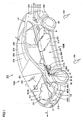
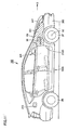
- Fig. 1 is a perspective view showing a schematic structure of hybrid vehicle 100 according to the embodiment.
- Fig. 2 is a block diagram showing the schematic structure in Fig. 1 .
- Fig. 3 is a perspective view showing a schematic structure of a body 500 of a vehicle main-unit 200 of hybrid vehicle 100.
- hybrid vehicle 100 includes vehicle main-unit 200 formed of a body and exterior parts, a pair of front wheels 2F arranged on a front side in a running direction D of hybrid vehicle 100, and rear wheels 2R arranged on a rear side in running direction D.
- Vehicle main-unit 200 includes an engine compartment ER arranged at the front, in running direction D, of hybrid vehicle 100, an occupant accommodating compartment CR adjacent to a rear side, in running direction D, of engine compartment ER, and a luggage compartment LR adjacent to a rear side, in running direction D, of occupant accommodating compartment CR.
- Body 500 includes a front wall 550 that is arranged on the front side in running direction D and defines engine compartment ER, a compartment wall 560 defining occupant accommodating compartment CR, and a rear wall 570 arranged on a rear side, in running direction D, of vehicle main-unit 200.
- Front wall 550 includes a front arm 501 that is arranged on the front side of vehicle main-unit 200 and extends in a width direction of vehicle main-unit 200, front side-walls 504 that continue to the opposite ends of front arm 501, respectively, and define side surface portions of engine compartment ER, and a front partition 510 arranged between engine compartment ER and occupant accommodating compartment CR.
- Each front side-wall 504 has a vertical width that increases as the position moves from front arm 501 toward front partition 510.
- Front side-wall 504 has a lengthwise middle portion that is curved for accepting front wheel 2F.
- Front side-wall 504 has a thickness that increases as the position moves from front arm 501 toward front partition 510.
- Compartment wall 560 includes front supports 503 that are arranged on side portions located at widthwise opposite ends of front partition 510, respectively, and extend in a height direction of vehicle main-unit 200, front pillars 507 connected to upper ends of front supports 503, respectively, and under supports 505 connected to lower ends of front supports 503, respectively.
- Body 500 is provided at its side surfaces with openings 212L and 212R that continue to occupant accommodating compartment CR for allowing entry of occupants.
- Each of openings 212L and 212R has a periphery that is defined by front support 503, under support 505, front pillar 507 and an edge of rear wall 570.
- a portion located forward, in running direction D, with respect to occupant accommodating compartment CR has a smaller thickness that a portion located rearward in running direction D.
- a plurality of exterior parts are attached to the surface of body 500 having the above structure. Thereby, vehicle main-unit 200 is formed.
- the exterior parts include, e.g., a front face 310 arranged on the front side of vehicle main-unit 200 in Fig. 1 , a front bumper 300 arranged under front face 310, and front fenders 301 covering front side-walls 504 shown in Fig. 3 as well as front and rear doors 312 and 313 for closing openings 212L and 212R.
- the exterior parts also include a hood 307 forming an upper lid of engine compartment ER, rear fenders 303 arranged rearward, in running direction D, with respect to rear doors 313, respectively, and a rear bumper 304 arranged under rear fenders 303.
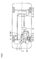
- driver seat DR for operating hybrid vehicle 100, a passenger seat neighboring, in the width direction of hybrid vehicle 100, to the driver seat, and rear seats behind the passenger seat and driver seat DR.
- driver seat DR is offset toward right side surface (one of the side surfaces) 100A of hybrid vehicle 100 with respect to a center line O of hybrid vehicle 100 extending in running direction D.
- a fuel tank 201 storing liquid fuel such as gasoline is arranged under the rear seats in occupant accommodating compartment CR.
- a battery (power storage unit) B such as a fuel cell or a capacitor of a large capacity is arranged rearward, in running direction D, with respect to the rear seats.
- Engine compartment ER accommodates an engine 4 of an internal combustion engine that generates a motive power driving front wheels 2F as well as a transaxle TR.
- Transaxle TR includes motor generators MG1 and MG2 driving front wheels 2F, a booster converter 20 that boosting an electric power supplied from battery B, inverters 30 and 40 that convert the DC power supplied from booster converter 20 to an AC power and supply it to motor generators MG1 and MG2, respectively, and a power splitting mechanism 3 formed of a planetary gear and others.
- Engine 4 is offset toward side surface 100A with respect to center line O, and transaxle TR is offset toward side surface 100B with respect to center line O.
- a center of gravity of a combination of engine 4 and transaxle TR is located on or near center line O to keep a widthwise balance of hybrid vehicle 100.
- a center of gravity of each of battery B and fuel tank 201 is located on or near center line O.
- a charging/power-supplying unit (i.e., electric power input/output unit) 90 that is an unit for electric charging and electric power supplying as well as a fueling unit 213 are arranged on a side surface of hybrid vehicle 100, and particularly on side surface 100B opposite to side surface 100A adjacent to driver seat DR.
- a steering wheel, steering shaft, steering gear and the like for steering front wheels 2F are arranged in or near driver seat DR.
- Charging/power-supplying unit 90 and fueling unit 213 keep a weight balance with respect to driver seat DR.
- charging/power-supplying unit 90 includes a connection unit 91 that is arranged on body 500 and has an opening for fitting a connector 190 thereinto, an openable lid 90A that can close an opening of connection unit 91 and an interconnection 92 connected to connection unit 91.
- Connector 190 includes a charging connector, an electric power supply connector or a charging/power-supplying connector.
- the charging connector is a connector for charging battery B with an electric power supplied from a commercial power (e.g., of a single-phase AC 100V in Japan).
- This charging connector is, e.g., a socket connected to a general home power supply.
- the power supply connector is a connector for supplying an electric power (e.g., of a single-phase AC 100V in Japan) supplied from hybrid vehicle 100 to an external load.
- the charging/power-supplying connector is a connector having both functions as the charging connector and the power-supply connector described above, can charge the battery with the power supplied from the commercial power and can also supply the power from hybrid vehicle 100 to the external load.
- a method of supplying and receiving the electric between connector 190 and charging/power-supplying unit 90 may be of a contact type in which a part of connector 190 can be in direct contact with at least a part of charging/power-supplying unit 90. Also, it may also be of an inductive type.
- Interconnection 92 is connected to a neutral point between motor generators MG1 and MG2, and the power supplied from connector 190 can be supplied to battery B via motor generators MG1 and MG2, inverters 30 and 40, and booster converter 20.
- charging/power-supplying unit 90 can externally supply the power stored in battery B from connector 190 via booster converter 20 and inverters 30 and 40.
- fueling unit 213 includes a nozzle receiver 215 that is formed in body 500 and has an opening, a fueling pipe 214 connected to nozzle receiver 215 and fuel tank 201, and an openable lid 213A that is arranged on an exterior part for closing an opening of nozzle receiver 215.
- Nozzle receiver 215 can receive a fueling nozzle of fueling connector 191 arranged outside hybrid vehicle 100.
- the supplied fuel such as gasoline flows through fueling pipe 214 into fuel tank 201.
- fueling unit 213 and charging/power-supplying unit 90 are arranged on the same side surface 100B of hybrid vehicle 100 as described above, a driver can remember the positions of charging/power-supplying unit 90 and fueling unit 213 without difficulty. Therefore, when the driver moves hybrid vehicle 100 into charging/fueling stand or the like, an error about the entry and stop directions of hybrid vehicle 100 can be reduced.
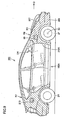
- Fig. 4 is a side view of hybrid vehicle 100.
- charging/power-supplying unit 90 can be located in any position on side surface 100B of hybrid vehicle 100.
- it may be located in any position on a side surface of rear bumper 304, rear fender 303, rear door 313, front door 312, front fender 301, a side surface of front bumper 300, a center pillar 305, a front pillar 302 or an under pillar 306.
- fueling unit 213 can be located in any position on side surface 100B.
- Charging/power-supplying unit 90 may be arranged in a region R1 of side surface 100B that is located forward in running direction D with respect to opening 212L, or in a region R2 thereof that is located rearward in running direction D with respect to opening 212L.
- Fueling unit 213 may be arranged in region R1 or R2 spaced from charging/power-supplying unit 90 with opening 212L therebetween.
- opening 212L is located between charging/power-supplying unit 90 and fueling unit 213 so that charging/power-supplying unit 90 and fueling unit 213 are spaced from each other in running direction D. Therefore, it is possible to suppress confusion about charging/power-supplying unit 90 and fueling unit 213 by the driver and the like.
- charging/power-supplying unit 90 is spaced from fueling unit 213, a hole that is formed in body 500 for fitting connection unit 91 of charging/power-supplying unit 90 thereinto can be spaced from a hole into which nozzle receiver 215 of fueling unit 213 is fitted, and it is possible to suppress formation of a portion locally having a low rigidity in body 500.
- Region R1 includes side surfaces of front fender 301 and front bumper 300, and region R2 includes side surfaces of rear fender 303 and rear bumper 304.
- Nozzle receiver 215 of fueling unit 213 receives the fueling nozzle of fueling connector 191 fitted thereinto, and supports fueling connector 191 through the fueling nozzle.
- Fueling connector 191 generally and internally has a regulating mechanism for regulating a fueling speed or rate, and is heavier than connector 190.
- Fueling unit 213 supporting heavy fueling connector 191 as described above has greater rigidity than connection unit 91.
- fueling unit 213 supports fueling pipe 214, and therefore must have greater rigidity than connection unit 91 connected to interconnection 92.
- connection unit 91 of smaller rigidity is located in region R1, and this structure can suppress excessive increase in rigidity of the front side of body 500 and can ensure an impact absorbing function of body 500.
- the thickness of body 500 located around charging/power-supplying unit 90 is smaller than the thickness of the portion of body 500 located around fueling unit 213.
- fueling unit 213 is arranged in side surface 100B and particularly at the rear of opening 212L. By arranging fueling unit 213 at the rear of opening 212L, therefore, it is possible to suppress the driver's erroneous recognition.
- fuel tank 201 is arranged under the rear seats, and fueling unit 213 is located in region R2 so that the length of fueling pipe 214 can be reduced.
- motor generators MG1 and MG2 are arranged in engine compartment ER, and charging/power-supplying unit 90 is arranged in region R1 as shown in Fig. 4 so that the length of interconnection 92 can be reduced.
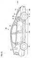
- charging/power-supplying unit 90 is arranged in a region R3 that is located in side surface 100B and particularly is located rearward in running direction D with respect to a shaft 53 connected to front wheels 2F, and is located forward in running direction D with respect to the edge of opening 212L.
- front side-wall 504 containing region R3 has the rigidity that increases as the position moves rearward in running direction D, and therefore has the rigidity that substantially allows appropriate supporting of connection unit 91 of charging/power-supplying unit 90. Accordingly, even when the charging and external power supplying operations are repeated, the secular deterioration of front side-wall 504 can be suppressed.
- charging/power-supplying unit 90 is arranged in a region R4 that is located in side surface 100B and particularly between the opening edge of opening 212L and the forward edge (viewed in running direction D) of side surface 100B, and more particularly is located above an upper end of front wheel 2F.
- charging/power-supplying unit 90 can be located in a position allowing easy fitting of connector 190 shown in Fig. 1 , and the charging and external power supplying operations can be performed efficiently.
- charging/power-supplying unit 90 is arranged in a region R5 that is located in side surface 100B and particularly is located forward in running direction D with respect to shaft 53.
- charging/power-supplying unit 90 By arranging charging/power-supplying unit 90 in the above position, it is possible to suppress contact between the interconnection of connector 190 and opened front door 312 in the state where charging/power-supplying unit 90 is fitted into connector 190 shown in Fig. 1 .
- Fig. 8 is a block diagram showing an example in which charging/power-supplying unit 90 and fueling unit 213 are arranged in side surface 100A on the driver seat DR side.
- Fig. 9 is a side view showing an example in which charging/power-supplying unit 90 and fueling unit 213 are arranged in side surface 100A on the driver seat DR side.
- both charging/power-supplying unit 90 and fueling unit 213 are arranged in side surface 100A and are close to driver seat DR. Therefore, the driver who left driver seat DR for performing the charging/power-supplying operation can immediately start the operation.
- Charging/power-supplying unit 90 and fueling unit 213 may be arranged in any position on side surface 100A.
- charging/power-supplying unit 90 is arranged in side surface 100A and particularly in a region R6 that is located forward, in running direction D, with respect to the opening edge of opening 212R on the driver seat DR side.
- Fueling unit 213 is arranged in side surface 100A and particularly in a region R7 that is located rearward, in running direction D, with respect to the opening edge of opening 212R.
- opening 212R is located between charging/power-supplying unit 90 and fueling unit 213 so that confusion about charging/power-supplying unit 90 and fueling unit 213 can be suppressed, and body 500 can keep the impact absorbing function.
- charging/power-supplying unit 90 is arranged in side surface 100A and particularly in a region R8 that is located rearward, in running direction D, with respect to shaft 53 and is located forward, in running direction D, with respect to the opening edge of opening 212R.
- this example can suppress secular deterioration of front side-wall 504, even when the charging and external power supplying operations are repeated.
- charging/power-supplying unit 90 is arranged in side surface 100A and particularly in a region R9 that is located forward, in running direction D, with respect to the opening edge of opening 212R and is located above front wheels 2F.
- this example can facilitate the charging and external power supplying operations and the fueling operation.
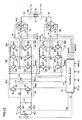
- Fig. 12 is a schematic block of hybrid vehicle 100 according to the embodiment of the invention. Referring to Fig. 12 , description will be given on a method of charging battery B with an AC current supplied from connector 190.
- a positive electrode of battery B is connected to a positive line PL1, and a negative electrode thereof is connected to a negative line NL1.
- a capacitor C1 is connected between positive and negative lines PL1 and NL1.
- Booster converter 20 is connected between positive and negative lines PL1 and NL1 on one side and positive and negative lines PL2 and NL2 on the other side.
- a capacitor C2 is connected between positive and negative lines PL2 and NL2.
- Inverter 30 is connected between motor generator MG1 and positive and negative lines PL2 and NL2.
- Inverter 40 is connected between motor generator MG2 and positive and negative lines PL2 and NL2.
- Motor generator MG1 includes a three-phase coil 11 as a stator coil
- motor generator MG2 includes a three-phase coil 12 as a stator coil.
- Booster converter 20 includes a reactor L1, NPN transistors Q1 and Q2, and diodes D1 and D2.
- One end of reactor L1 is connected to positive line PL1, and the other end is connected to a midpoint between NPN transistors Q1 and Q2, i.e., to a point between an emitter of NPN transistor Q1 and a collector of NPN transistor Q2.
- NPN transistors Q1 and Q2 are connected in series between positive line PL1 and negative lines NL1 and NL2.
- a collector of NPN transistor Q1 is connected to positive line PL2 of inverters 30 and 40, and an emitter of NPN transistor Q2 is connected to negative lines NL1 and NL2.
- Diodes D1 and D2 are arranged corresponding to NPN transistors Q1 and Q2, respectively, and each are connected between the collector and emitter of the corresponding transistor Q1 or Q2 for passing a current from the emitter side to the collector side thereof.
- Inverter 30 is formed of U-, V- and W-phase arms 31, 32 and 33, which are connected, in parallel with each other, between positive and negative lines PL2 and NL2.
- U-phase arm 31 is formed of NPN transistors Q3 and Q4 connected together in series.
- V-phase arm 32 is formed of NPN transistors Q5 and Q6 connected together in series.
- W-phase arm 33 is formed of NPN transistors Q7 and Q8 connected together in series.
- Diodes D3 - D8 are arranged corresponding to NPN transistors Q3 - Q8, respectively, and each are connected between a collector and an emitter of the corresponding transistor for passing the current form the emitter side to the collector side.
- a midpoint of each phase arm of inverter 30 is connected to a phase end of each phase coil of a three-phase coil 11 included in motor generator MG1.
- motor generator MG1 is a three-phase permanent magnet motor, and one end of each of its three, i.e., U-, V- and W-phase coils is commonly connected to a neutral point M1.
- the other ends of the U-, V- and W-phase coils are connected to midpoints between NPN transistors Q3 and Q4, between NPN transistors Q5 and Q6, and between NPN transistors Q7 and Q8, respectively.
- Inverter 40 is connected, in parallel with inverter 30, between opposite ends of capacitor C2.
- Inverter 40 is formed of U-, V- and W-phase arms 41, 42 and 43, which are connected, in parallel with each other, between positive and negative lines PL2 and NL2.
- U-phase arm 41 is formed of NPN transistors Q9 and Q10 connected together in series.
- V-phase arm 42 is formed of NPN transistors Q11 and Q12 connected together in series.
- W-phase arm 43 is formed of NPN transistors Q13 and Q14 connected together in series.
- NPN transistors Q9 - Q14 correspond to NPN transistors Q3 - Q8 of inverter 30, respectively.
- inverter 40 has the same structure as inverter 30.
- Diodes D9 - D14 are arranged corresponding to NPN transistors Q9 - Q14, respectively, and each are connected between a collector and an emitter of the corresponding transistor for passing the current form the emitter side to the collector side.
- a midpoint of each phase arm of inverter 40 is connected to a phase end of each phase coil of three-phase coil 12 included in motor generator MG2.
- motor generator MG2 is a three-phase permanent magnet motor, and one end of each of its three, i.e., U-, V- and W-phase coils is commonly connected to neutral point M2.
- the other ends of the U-, V- and W-phase coils are connected to midpoints between NPN transistors Q9 and Q10, between NPN transistors Q11 and Q12, and between NPN transistors Q 13 and Q 14, respectively.
- Battery B is formed of a secondary battery such as a nickel hydrogen battery or a lithium-ion battery.
- a voltage sensor 10 senses a battery voltage Vb provided from battery B, and provides sensed battery voltage Vb to a control device 70.
- System relays SR1 and SR2 are turned on/off in response to a signal SE from control device 70. More specifically, system relays SR1 and SR2 are turned on in response to signal SE at an H-level (logical high level) from control device 70, and is turned off in response to signal SE at an L-level (logical low level) from control device 70.
- Capacitor C1 smoothes the DC voltage supplied from battery B, and supplies the smoothed DC voltage to booster converter 20.
- Booster converter 20 boosts the DC voltage supplied from capacitor C1, and supplies it to capacitor C2. More specifically, when booster converter 20 receives a signal PWC from control device 70, it boosts and supplies the DC voltage to capacitor C2 corresponding to a period for which signal PWC keeps NPN transistor Q2 on. In this case, signal PWC keeps NPN transistor Q1 off. According to signal PWC from control device 70, booster converter 20 steps down the DC voltage supplied from inverter 30 and/or 40 via capacitor C2, and charges battery B.
- Capacitor C2 smoothes the DC voltage supplied from booster converter 20, and supplies the smoothed DC voltage to inverters 30 and 40.
- a voltage sensor 13 senses a voltage between the opposite ends of capacitor C2, i.e., an output voltage Vm of booster converter 20 (corresponding to the input voltage provided to inverters 30 and 40 (this is true in the following description)), and provides sensed output voltage Vm to control device 70.
- inverter 30 When inverter 30 is supplied with the DC voltage from capacitor C2, inverter 30 converts the DC voltage to the AC voltage based on a signal PWM1 provided from control device 70, and drives motor generator MG1. Thereby, motor generator MG1 is driven to generate a torque indicated by a torque command value TR1. Inverter 30 converts the AC voltage that is generated by motor generator MG1 during regenerative braking of the hybrid vehicle equipped with the power output device to the DC voltage based on signal PWM1 provided from control device 70, and supplies the converted DC voltage to booster converter 20 via capacitor C2.
- the regenerative braking includes braking that is performed when the driver of the hybrid vehicle operates a brake pedal, and this braking is accompanied by regenerative power generation. Also, the regenerative braking includes deceleration (or stop of acceleration) of the vehicle that is not performed by a foot brake operation, but is performed by releasing an accelerator pedal during running while causing the regenerative power generation.
- Inverter 30 drives motor generator MG1 according to signal PWM1 from control device 70 so that an AC voltage VAL for the commercial power can be output from terminals 61 and 62 of charging/power-supplying unit 90.
- inverter 40 When inverter 40 is supplied with the DC voltage from capacitor C2, it converts the DC voltage to the AC voltage based on a signal PWM2 from control device 70 for driving motor generator MG2. Thereby, motor generator MG2 is driven to generate a torque indicated by a torque command value TR2. Further, when the hybrid vehicle equipped with the motive power output device performs the regenerative braking, inverter 40 converts the AC voltage generated by motor generator MG2 to the DC voltage based on signal PWM2 from control device 70, and supplies the converted DC voltage to booster converter 20 via capacitor C2.
- inverter 40 drives motor generator MG2 according to signal PWM2 from control device 70 so that AC voltage VAC for the commercial power can be output from terminals 61 and 62 of charging/power-supplying unit 90.
- a current sensor 14 senses a motor current MCRT1 flowing through motor generator MG1, and provides sensed motor current MCRT1 to control device 70.
- a current sensor 15 senses a motor current MCRT2 flowing through motor generator MG2, and provides sensed motor current MCRT2 to control device 70.
- Charging/power-supplying unit 90 includes a primary coil 51 and a secondary coil 52.
- Primary coil 51 is connected between neutral point M1 of three-phase coil 11 included in motor generator MG1 and neutral point M2 of three-phase coil 12 included in motor generator MG2.
- Charging/power-supplying unit 90 converts the AC voltage appearing between neutral points M1 and M2 of motor generators MG1 and MG2 to AC voltage VAC for the commercial power, and outputs it from terminals 61 and 62.
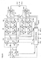
- Fig. 13 is a schematic block diagram of hybrid vehicle 100 according to the embodiment of the invention. Referring to Fig. 13 , description will be given on a method of supplying the AC current to connector 190 and externally supplying the electric power. Referring to Fig. 13 , six transistors in each of inverters 30 and 40 that are formed of the three-phase bridge circuits, respectively, can attain on and off states, of which combination patters are eight in number. In two of these eight switching patterns, an inter-phase voltage is zero, and this voltage state is referred to as a zero-voltage vector.
- Fig. 13 shows the three transistors of the upper arm of inverter 30 as an upper arm 30A, and also shows the three transistors of the lower arm of inverter 30 as a lower arm 30B.
- Fig. 13 shows the three transistors of the upper arm of inverter 40 as an upper arm 40A, and also shows the three transistors of the lower arm of inverter 40 as a lower arm 40B.
- this zero-phase equivalent circuit can be regarded as a single-phase PWM converter of which input is the single-phase AC power provided to neutral points M1 and M2 via power input lines ACL1 (92) and ACL2 (92) of connector 190. Accordingly, the zero-voltage vector is changed in each of inverters 30 and 40 to perform the switching control so that inverters 30 and 40 may operate as arms of the single-phase PWM converter. Thereby, the AC power provided from power input lines ACL1 and ACL2 can be converted to the DC power, which is provided to positive line PL2. The DC power thus converted is supplied to booster converter 20 via capacitor C2 for charging battery B.
- Fig. 14 is a perspective view showing a part of a frame equipped body 600
- Fig. 15 is a plan view showing a frame 650 of frame-equipped body 600 shown in Fig. 14 .
- frame-equipped body 600 includes frame 650, and a box-shaped body 610 fixed to an upper surface of frame 650.
- Body 610 has a front portion 630 defining engine compartment ER.
- Front portion 630 includes an upper support portion 620 arranged on a front surface, a lower support portion 621, and front fender portions 622 defining side surfaces of engine compartment ER.
- Upper edge portions of upper support portion 620 and front fender portions 622 define a part of the opening of engine compartment ER, and lower support portion 621 is arranged under upper support portion 620.
- the central portion of upper support portion 620, the upper edge portions of front fender portions 622 and the central portion of lower support portion 621 have reduced thicknesses so that a flexible structure of a reduced weight is implemented. Thereby, this structure can suppress increase in vibration of a hood panel (not shown).
- Charging/power-supplying unit 90 is arranged in front fender portion 622 having the flexible structure. Thereby, the provision of charging/power-supplying unit 90 can suppress the increase in rigidity of front fender portion 622 and therefore the increase in vibration of the hood panel to a higher extent, as compared with the case where fueling unit 213 shown in Fig. 1 is arranged therein.
- frame 650 includes a pair of side frames 651 extending in running direction D of hybrid vehicle 100, a plurality of side support portions 652 - 660 arranged between these side frames 651, and a plurality of fixing portions 670 fixing body 610 and frame 650 together. Since frame-equipped body 600 includes frame 650 described above, it can ensure high rigidity. For example, for a towing operation, frame 650 may be provided with a towing portion so that deformation or the like of frame-equipped body 600 can be suppressed.
- the embodiment has been described based on the so-called "series parallel hybrid” that is a certain type of hybrid.
- a series hybrid i.e., a hybrid type in which the vehicle includes an engine that is an internal combustion engine requiring fueling, and a running motor (i.e., motor for running) driving wheels by an electric power generated by the engine and/or by an electric power stored in a battery.
- a running motor i.e., motor for running
- the embodiment can be applied to a parallel hybrid in which both the engine and the motor can provide motive powers to a drive shaft.
- a dedicated charging/power-supplying device that has functions as an inverter and a DC/DC converter may be employed for performing the charging and the electric power supplying.
- This dedicated charging/power-supplying device is connected, e.g., between capacitor C1 and system relays SR1 and SR2 in Fig. 12 .
- the invention can be applied to a fuel cell vehicle.
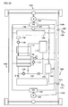
- Fig. 16 is a schematic view schematically showing a structure in which the invention is applied to a fuel cell vehicle 1000.
- fuel cell vehicle 1000 includes a fuel cell 1100, a power storage unit 1200 such as a capacitor, an inverter 1400 for running, an inverter 1600 for accessories, an accessory motor 1700 and an ECU (Electronic Control Unit) 1800.
- a control device of an electric system according to the embodiment is implemented, e.g., by programs executed by ECU 1800.
- Fuel cell 1100 generates the electric power by a chemical reaction of hydrogen and oxygen in the air.
- the electric power generated by fuel cell 1100 is stored in power storage unit 1200 or is consumed by devices mounted on fuel cell vehicle 1000. Since fuel cell 1100 can employ known general technologies, further description thereof is not repeated.
- Power storage unit 1200 is formed of, e.g., a plurality of cells (electric double-layer capacitors) connected in series, and may be a secondary battery or the like.
- Inverter 1400 for running converts the DC power supplied from fuel cell 1100 and power storage unit 1200 to the AC power, and drives a running motor 1500. During regenerative braking, it converts the AC power generated by running motor 1500 to the DC power, and supplies it to power storage unit 1200.
- Running motor 1500 is a three-phase AC dynamo-electric machine.
- U-, V- and W-phase coils are wound around a stator of running motor 1500. Ends on one side of U-, V- and W-phase coils are connected together at a neutral point. The other ends of the U-, V- and W-phase coils are connected to running inverter 1400.
- connection unit 1090 An interconnection 1192B of a connection unit (second connection unit) 1090 is connected to the neutral point of running motor 1500.
- connection unit 1090 it is possible to connect, e.g., a connector 1190 connected to the AC power supply such as a general home power supply connector. Therefore, the AC power can be supplied to running motor 1500.
- Accessory motor 1700 is likewise a three-phase AC dynamo-electric machine.
- U-, V- and W-phase coils are wound around a stator of accessory motor 1700. Ends on one side of U-, V- and W-phase coils thereof are connected together at a neutral point. The other ends of the U-, V- and W-phase coils are connected to accessory inverter 1600.
- connection unit 1090 An interconnection 1192A of connection unit 1090 is connected to the neutral point of accessory motor 1700 so that the AC power can be supplied to a neutral point of accessory motor 1700 from connection unit 1090 from connector 1190 via connection unit 1090.
- Connection unit 1090 described above is arranged on one side surface 100A of fuel cell vehicle 1000.
- the AC power supplied to running motor 1500 and accessory motor 1700 is converted to the DC power by running inverter 1400 and accessory inverter 1600, and is supplied to power storage unit 1200 so that power storage unit 1200 is charged.
- running motor 1500 drives fuel cell vehicle 1000 to run.
- the wheels (not shown) drive running motor 1500 to operate as an electric power generator.
- running motor 1500 operates as a regenerative brake converting the braking energy to the electric energy.
- Accessory inverter 1600 converts the DC power supplied from fuel cell 1100 and power storage unit 1200 to the AC power, and drives accessory motor 1700.
- Accessory motor 1700 drives the accessories that operate for operating fuel cell 1100. The accessories that are driven for operating fuel cell 1100 will be described later.
- a voltmeter 1802 and a start switch 1804 are connected to ECU 1800.
- the voltmeter senses a system voltage (i.e., a voltage of power storage unit 1200), and transmits a signal indicating a result of the sensing to ECU 1800.
- a driver of fuel cell vehicle 1000 can operate start switch 1804. When start switch 1804 is turned on, ECU 1800 starts the system of the vehicle. When start switch 1804 is turned off, ECU 1800 stops the system of the vehicle.
- ECU 1800 controls the devices and the like mounted on fuel cell vehicle 1000 to set the vehicle in a desired drive state based on a driving state of the vehicle, an accelerator position sensed by an accelerator position sensor (not shown), a press-down degree of an brake pedal, a shift position, a voltage of power storage unit 1200 and an operated state of start switch 1804 as well as maps and programs stored in a ROM (Read Only Memory).
- ROM Read Only Memory
- Fuel cell vehicle 1000 includes a hydrogen tank 1102, a hydrogen pump 1104, an air filter 1106, an air pump 1108, a humidifier 1110, a water pump 1112 and a diluter 1114.
- Hydrogen tank 1102 stores hydrogen.
- a hydrogen-storing alloy may be used instead of hydrogen tank 1102.
- Hydrogen tank 1102 is connected to a connection unit 1213 that supplies, to hydrogen tank 1102, the hydrogen supplied from a hydrogen supply connection unit 1191.
- connection units 1213 and 1090 are both arranged on side surface 100A, confusion about the side surfaces where connection units 1213 and 1090 are arranged can be suppressed when the driver performs the charging operation or the hydrogen-supplying operation.
- connection units 1213 and 1090 are arranged on the same side surface 100A, it is possible to suppress an error about the entry direction when the driver moves the vehicle into the charging/hydrogen-supplying station.
- connection units 1213 and 1090 are spaced from each other in the longitudinal direction of the vehicle as shown in Fig. 11 , it is possible to suppress hydrogen brittle fracture that may occur in and around connection unit 1090 due to the hydrogen supplied from hydrogen supply connection unit 1191.
- connection units 1213 and 1090 For example, the opening that continues to the occupant accommodating compartment and allows entry of an occupant is located between connection units 1213 and 1090.
- This structure can suppress the hydrogen brittle fracture in and around connection unit 1090, and can also suppress the confusion about connection units 1213 and 1090 by an operator.
- connection potion 1213 in the first embodiment may be applied to connection units 1213 and 1090.
- Fig. 17 is a perspective view showing structures of and around connection unit 1213.
- connection unit 1213 is accommodated in an accommodation chamber 1213C formed in side surface 100A of the vehicle.
- Accommodation chamber 1213C has an outward opening 1213B, which can be closed by an openable lid 1213A pivotably arranged on side surface 100A.
- Connection unit 1213 can accept the nozzle unit of hydrogen supply connection unit 1191.
- an operator opens lid 1213A, fits hydrogen supply connection unit 1191 into connection unit 1213 and starts the supplying of hydrogen.
- the opening of connection unit 1213 is closed by an openable inner lid (not shown), and opening 1213B is closed by lid 1213A.
- connection unit 1213 is accommodated in closable accommodation chamber 1213C as described above, external leakage of the hydrogen can be suppressed, and it is possible to suppress corrosion of the vehicle body that may occur in a portion around accommodation chamber 1213C due to the hydrogen.
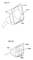
- Fig. 18 is a perspective view showing structures of and around connection unit 1090. As shown in Fig. 18 , connection unit 1090 is accommodated in an accommodation chamber 1090C that is independent of accommodation chamber 1213C.
- connection unit 1090 with the hydrogen can be suppressed, and corrosion of connection unit 1090 can be suppressed.
- connection units 1090 and 1213 when an opening 1212 is present between connection units 1090 and 1213, an appropriate distance is kept between connection units 1090 and 1213, and the contact of hydrogen with connection unit 1090 can be suppressed.
- hydrogen pump 1104 feeds the hydrogen stored in hydrogen tank 1102 to an anode side of fuel cell 1100.
- hydrogen pump 1104 is driven to perform a stop processing of discharging residual hydrogen from the anode side of fuel cell 1100.
- Accessory motor 1700 drives hydrogen pump 1104.
- Air pump 1108 feeds the air to the cathode side of fuel cell 1100.
- air pump 1108 is drive to take in the air through air filter 1106, and the air is humidified by humidifier 1110 and then is fed toward the cathode of fuel cell 1100.
- air pump 1108 is driven. Thereby, the air taken through air filter 1106 is fed toward the cathode of fuel cell 1100 without being humidified, and the stop processing of drying fuel cell 1100 is performed.
- Air pump 1108 is driven by accessory motor 1700.
- Water pump 1112 discharges cooling water for cooling fuel cell 1100.
- the cooling water discharged by water pump 1112 circulates in fuel cell 1100.
- Water pump 1112 is driven by accessory motor 1700.
- the hydrogen passed through the anode side of fuel cell 1100 and the air passed through the cathode side are led to diluter 1114.
- Diluter 1114 dilutes the hydrogen and the diluted hydrogen is externally discharged from the vehicle.
- accessory motor 1700 is provided corresponding to hydrogen pump 1104, air pump 1108 and water pump 1112, respectively.
- accessory motor 1700 is driven by converting the electric power supplied from power storage unit 1200 from the DC power to the AC power.
- a configuration that drives accessory motor 1700 by the DC power without using accessory inverter 1600 may be employed.
- connection unit 1213 the hydrogen used in fuel cell 1100 is supplied through connection unit 1213.
- this is not restrictive.
- connection unit 1213 is supplied with the methanol.
- Connection unit 1213 is connected to a methanol tank (not shown) employed independently of hydrogen tank 1102, and the methanol tank stores the methanol.
- the hydrogen is produced by supplying the methanol stored in the methanol tank and the water to the reformer, and is stored in hydrogen tank 1102.
- a configuration that supplies the produced hydrogen directly to the fuel cell may be employed.
- connection unit In the direct methanol system that directly supplies the methanol to the fuel cell, the connection unit is likewise supplied with the methanol.
- the methanol is supplied together with the water to the anode of fuel cell 1100, and is decomposed to produce hydrogen ions, electrons and carbon dioxide, using catalyst such as platinum.
- the hydrogen ions move through an electrolytic membrane toward the cathode, and reacts with the oxygen in the air to change into water.
- the electrons are supplied as an electric power through terminals.
- a methanol tank connected to connection unit 1213 stores the methanol supplied from connection unit 1213.
- the methanol stored in the methanol tank is supplied to fuel cell 1100.
- connection unit 1213 is supplied with the ethanol.
- the ethanol reforming device is supplied with the ethanol and the water to produce the hydrogen and the carbon dioxide. The hydrogen thus produce is supplied to the fuel cell to obtain the electric power.
- Fuel cell vehicle 1000 equipped with the ethanol reforming device is supplied with the ethanol through connection unit 1213, and stores it in the ethanol tank.
- the ethanol stored in the ethanol tank is supplied to the ethanol reforming device.
- the invention can be applied to various types of fuel cell vehicles 1000.
- the third embodiment has been described in connection with the fuel cell vehicle in which power storage unit 1200 is chargeable and the fuel other than the electric power can be supplied, this is not restrictive.
- the invention may be applied to the fuel cell vehicle in which the DC power stored in power storage unit 1200 can be converted to the AC power, and can be supplied to an external load, and fuel other the electric power can be supplied to the fuel cell to generate a motive power.
- the invention relates to the hybrid vehicle, and particularly is suitable for the hybrid vehicle that allows the electric power supplying and/or the external electric power supplying.
Description
- The present invention relates to a vehicle, particularly to a vehicle supplied with multiple kinds of energy sources, and typically to a hybrid vehicle that can be charged and/or can be externally supplied with an electric power.
- There have been proposed various types of vehicles such as hybrid vehicles and electric vehicles that are developed in view of environment. The electric vehicle can drive wheels by an onboard battery. For example, Japanese Patent Laying-Open No.
11-318004 - The hybrid vehicle is equipped with a power storage device formed of a secondary battery or a capacitor, and generates a drive power from an electric power stored in the power storage device via a motor generator. Also, it generates a drive power by an engine.
- For example, Japanese Patent Laying-Open No.
8-154307 - There is already proposed a hybrid vehicle in which an external power source such as a system power supply or a solar battery can charge an onboard power storage device.
- For example, Japanese Patent Laying-Open No.
2005-204361 - Neither Japanese Patent Laying-Open No.
11-318004 8-154307 2005-204361 - In connection with the positional relationship between fuel supply port and the charging unit, the charging unit and the fuel supply port are arranged on different side surfaces of the vehicle, respectively. When the vehicle having the charging unit and the fuel supply port in the above positions is electrically charged or fueled at a charging/fueling stand or station, the vehicle must be positioned such that the side surface provided with the charging unit is located on a charging device side and the fuel supply port is located on a fueling device side.
- However, a driver is liable to confuse the side surfaces provided with the power supply unit and the fuel supply port, and must move the vehicle into the charging/fueling stand with attention given to a direction of the vehicle. This increases a load on the driver in a stage preceding the charging/fueling operation.
- Document
JP 2001 105903A - Document XP000852374 ("Battery hopes charged" by Jose Crosse) discloses an electric vehicle, which comprises an electric motor as the main drive source. In addition, an auxiliary generator driven by an additional engine for charging on-board batteries and/or assisting the electric motor is provided.
- The present invention has been developed in view of the above matters, and an object of the invention is to suppress driver's confusion about positions of a charging/power-supplying unit (i.e., electric charging and electric power-supplying unit) and a fuel supply port, and thereby to reduce a load on a driver in a stage preceding charging/fueling operation.
- This object is solved by a hybrid vehicle as set out in
claim 1. - Advantageous developments are defined in the dependent claims.
- A hybrid vehicle according to the invention includes a fuel tank for storing fuel; an internal combustion engine for generating a motive power, using the fuel supplied from the fuel tank; a fueling unit being connectable to a fuel-supply connection unit for supplying the fuel supplied from the fuel-supply connection unit to the fuel tank; an motor generator for supplying the motive power to a wheel; a power storage unit for storing an electric power to be supplied to the motor generator; and an electric power input/output unit being connectable to an electric connection unit for supplying, through the electric connection unit, the electric power to the power storage unit and/or externally supplying the electric power stored in the power storage unit. The electric power input/output unit and the fueling unit are arranged on the same side surface of the vehicle.
- According to the invention, the hybrid vehicle further includes an occupant accommodating compartment for accommodating an occupant; and an entry opening formed in the vehicle and communicating with the occupant accommodating compartment. The entry opening is positioned between the fueling unit and the electric power input/output unit.
- Preferably, the fueling unit is located rearward, in a running direction of the vehicle, with respect to the entry opening, and the electric power input/output unit is arranged forward, in the running direction of the vehicle, with respect to the entry opening.
- Preferably, the wheel includes a front wheel located forward, in the running direction of the vehicle, with respect to the entry opening and a rear wheel located rearward, in the running direction of the vehicle, with respect to the entry opening. The hybrid vehicle further includes a shaft connected to the front wheel for transmitting a motive power from the motor generator or the internal combustion engine to the rear wheel. The electric power input/output unit is located forward, in the running direction of the vehicle, with respect to the entry opening and rearward, in the running direction, with respect to the shaft.
- Preferably, the wheel includes a front wheel arranged forward, in the running direction of the vehicle, with respect to the occupant opening and a rear wheel arranged rearward, in the running direction of the vehicle, with respect to the occupant opening. The electric power input/output unit is arranged in a position on the side surface of the vehicle higher than the front wheel.
- Preferably, the hybrid vehicle further includes an occupant accommodating compartment for accommodating an occupant; and a driver seat arranged in the occupant accommodating compartment and allowing operation of the vehicle. The driver seat is located on the side surface side provided with the electric power input/output unit and the fueling unit with respect to a virtual center line of the vehicle extending in a running direction of the vehicle.
- Preferably, the hybrid vehicle further includes an occupant accommodating compartment for accommodating an occupant; and a driver seat arranged in the occupant accommodating compartment and allowing operation of the vehicle. The driver seat is located on the side surface side opposite to the side surface provided with the electric power input/output unit and the fueling unit with respect to a virtual center line of the vehicle extending in a running direction of the vehicle.
- Preferably, the motor generator includes a first motor generator having a first multi-phase winding and a first neutral point of the first multi-phase winding, and a second motor generator having a second multi-phase winding and a second neutral point of the second multi-phase winding. The electric power input/output unit includes a first interconnection connected to the first neutral point and a second interconnection connected to the second neutral point. The hybrid vehicle further includes a first inverter for supplying the electric power received from the power storage unit to the first motor generator, a second inverter for supplying the electric power received from the power storage unit to the second motor generator, and an inverter control unit controlling the first and second inverters. Further, the inverter control unit can control the first and second inverters to convert the AC power supplied from the electric power input/output unit to the first and second neutral points to the DC power, and to supply the DC power to the power storage unit, and/or can control the first and second inverters to convert the DC power supplied from the power storage unit to the first and second inverters to the AC power, and to supply the AC power to the electric power input/output unit.
- Preferably, the motor generator includes a first motor generator having a first multi-phase winding and a first neutral point of the first multi-phase winding, and a second motor generator having a second multi-phase winding and a second neutral point of the second multi-phase winding. The electric power input/output unit includes a first interconnection connected to the first neutral point and a second interconnection connected to the second neutral point. The hybrid vehicle further includes a first inverter for supplying the electric power received from the power storage unit to the first motor generator, a second inverter for supplying the electric power received from the power storage unit to the second motor generator, and an inverter control unit controlling the first and second inverters. The inverter control unit controls the first and second inverters to convert the AC power externally provided via the electric power input/output unit to the first and second neutral points to the DC power, and to provide the DC power to the power storage unit.
- A vehicle includes a first drive unit driven by a first energy source; a first storage unit for storing the first energy source; a first energy accepting unit removably connected to a first energy supply unit for receiving the first energy source; a first connection unit connected to the first energy accepting unit and leading the first energy source supplied to the first energy accepting unit to the first storage unit; a first accommodation chamber accommodating the first energy accepting unit; a first lid member for opening and closing an opening of the first accommodation chamber; a second drive unit driven by a second energy source different from the first energy source; a second storage unit for storing the second energy source; a second energy accepting unit removably connected to a second energy supply unit for receiving the second energy source; a second connection unit connected to the second energy accepting unit and leading the second energy source supplied to the second energy accepting unit to the second storage unit; a second accommodation chamber accommodating the second energy accepting unit and being independent of the first accommodation chamber; and a second lid member for opening and closing an opening of the second accommodation chamber. The first and second energy accepting units are arranged on the same side surface of the vehicle. Preferably, the vehicle further includes an occupant accommodating compartment for accommodating an occupant; an entry opening formed in the vehicle and connecting to the occupant accommodating compartment. The entry opening is located between the first and second energy accepting units.
- According to the hybrid vehicle of the invention, since the fueling unit and the charging/power-supplying unit are arranged on the same side surface of the vehicle, the driver does not confuse the positions of the fueling unit and the charging/power-supplying unit, and can suppress the increase in load on the driver in a stage preceding the charging/fueling operation.
-
-
Fig. 1 is a perspective view showing a schematic structure of a hybrid vehicle according to an embodiment. -
Fig. 2 is a block diagram showing the schematic structure inFig. 1 . -
Fig. 3 is a perspective view showing a schematic structure of a body of a vehicle main-unit of the hybrid vehicle. -
Fig. 4 is a side view of the hybrid vehicle. -
Fig. 5 is a side view showing a first modification of the hybrid vehicle according to the embodiment. -
Fig. 6 is a side view showing a second modification of the hybrid vehicle according to the embodiment. -
Fig. 7 is a side view showing a third modification of the hybrid vehicle according to the embodiment. -
Fig. 8 is a block diagram showing an example in which a charging/power-supplying unit and a fueling unit are arranged on a side surface on a driver seat side. -
Fig. 9 is a side view showing a fourth modification of the hybrid vehicle according to the embodiment. -
Fig. 10 is a side view showing a fifth modification of the hybrid vehicle according to the embodiment. -
Fig. 11 is a side view showing a sixth modification of the hybrid vehicle according to the embodiment. -
Fig. 12 is a schematic block diagram of the hybrid vehicle according to the embodiment of the invention, and illustrates external power supplying. -
Fig. 13 is a schematic block diagram of the hybrid vehicle according to the embodiment of the invention, and illustrates charging of a battery. -
Fig. 14 is a perspective view showing a part of a frame-equipped body. -
Fig. 15 is a plan view showing a frame of the frame-equipped body shown inFig. 14 . -
Fig. 16 is a schematic view schematically showing a structure in which the invention is applied to a fuel cell vehicle. -
Fig. 17 is a perspective view showing structures of and around a connection unit. -
Fig. 18 is a perspective view showing structures of and around the connection unit. - Embodiments of the invention will now be described with reference to the drawings. In the following description, the same or corresponding portions bear the same reference numbers, and description thereof is not repeated.
- Referring to
Figs. 1 to 13 , description will be given on ahybrid vehicle 100 according to an embodiment.Fig. 1 is a perspective view showing a schematic structure ofhybrid vehicle 100 according to the embodiment.Fig. 2 is a block diagram showing the schematic structure inFig. 1 .Fig. 3 is a perspective view showing a schematic structure of abody 500 of a vehicle main-unit 200 ofhybrid vehicle 100. - Referring to
Fig. 1 ,hybrid vehicle 100 includes vehicle main-unit 200 formed of a body and exterior parts, a pair offront wheels 2F arranged on a front side in a running direction D ofhybrid vehicle 100, andrear wheels 2R arranged on a rear side in running direction D. - Vehicle main-
unit 200 includes an engine compartment ER arranged at the front, in running direction D, ofhybrid vehicle 100, an occupant accommodating compartment CR adjacent to a rear side, in running direction D, of engine compartment ER, and a luggage compartment LR adjacent to a rear side, in running direction D, of occupant accommodating compartment CR. - For example, as shown in
Fig. 3 , a unitized body is employed asbody 500 of vehicle main-unit 200.Body 500 includes afront wall 550 that is arranged on the front side in running direction D and defines engine compartment ER, acompartment wall 560 defining occupant accommodating compartment CR, and arear wall 570 arranged on a rear side, in running direction D, of vehicle main-unit 200. -
Front wall 550 includes afront arm 501 that is arranged on the front side of vehicle main-unit 200 and extends in a width direction of vehicle main-unit 200, front side-walls 504 that continue to the opposite ends offront arm 501, respectively, and define side surface portions of engine compartment ER, and afront partition 510 arranged between engine compartment ER and occupant accommodating compartment CR. - Each front side-
wall 504 has a vertical width that increases as the position moves fromfront arm 501 towardfront partition 510. Front side-wall 504 has a lengthwise middle portion that is curved for acceptingfront wheel 2F. - Front side-
wall 504 has a thickness that increases as the position moves fromfront arm 501 towardfront partition 510. -
Compartment wall 560 includesfront supports 503 that are arranged on side portions located at widthwise opposite ends offront partition 510, respectively, and extend in a height direction of vehicle main-unit 200,front pillars 507 connected to upper ends of front supports 503, respectively, and undersupports 505 connected to lower ends of front supports 503, respectively. -
Body 500 is provided at its side surfaces withopenings openings front support 503, undersupport 505,front pillar 507 and an edge ofrear wall 570. - In
body 500, a portion located forward, in running direction D, with respect to occupant accommodating compartment CR has a smaller thickness that a portion located rearward in running direction D. Thereby, when head-on collision occurs, a front side ofbody 500 deforms to absorb an impact for protecting the inside of occupant accommodating compartment CR. - A plurality of exterior parts are attached to the surface of
body 500 having the above structure. Thereby, vehicle main-unit 200 is formed. - The exterior parts include, e.g., a
front face 310 arranged on the front side of vehicle main-unit 200 inFig. 1 , afront bumper 300 arranged underfront face 310, andfront fenders 301 covering front side-walls 504 shown inFig. 3 as well as front andrear doors openings - The exterior parts also include a
hood 307 forming an upper lid of engine compartment ER,rear fenders 303 arranged rearward, in running direction D, with respect torear doors 313, respectively, and arear bumper 304 arranged underrear fenders 303. - In occupant accommodating compartment CR, there are arranged a driver seat DR for operating
hybrid vehicle 100, a passenger seat neighboring, in the width direction ofhybrid vehicle 100, to the driver seat, and rear seats behind the passenger seat and driver seat DR. In the example shown inFig. 1 , driver seat DR is offset toward right side surface (one of the side surfaces) 100A ofhybrid vehicle 100 with respect to a center line O ofhybrid vehicle 100 extending in running direction D. - As shown in
Fig. 1 , afuel tank 201 storing liquid fuel such as gasoline is arranged under the rear seats in occupant accommodating compartment CR. A battery (power storage unit) B such as a fuel cell or a capacitor of a large capacity is arranged rearward, in running direction D, with respect to the rear seats. - Engine compartment ER accommodates an
engine 4 of an internal combustion engine that generates a motive power drivingfront wheels 2F as well as a transaxle TR. - Transaxle TR includes motor generators MG1 and MG2 driving
front wheels 2F, abooster converter 20 that boosting an electric power supplied from battery B,inverters booster converter 20 to an AC power and supply it to motor generators MG1 and MG2, respectively, and apower splitting mechanism 3 formed of a planetary gear and others. -
Engine 4 is offset towardside surface 100A with respect to center line O, and transaxle TR is offset towardside surface 100B with respect to center line O. A center of gravity of a combination ofengine 4 and transaxle TR is located on or near center line O to keep a widthwise balance ofhybrid vehicle 100. - Further, a center of gravity of each of battery B and
fuel tank 201 is located on or near center line O. - A charging/power-supplying unit (i.e., electric power input/output unit) 90 that is an unit for electric charging and electric power supplying as well as a fueling
unit 213 are arranged on a side surface ofhybrid vehicle 100, and particularly onside surface 100B opposite toside surface 100A adjacent to driver seat DR. A steering wheel, steering shaft, steering gear and the like for steeringfront wheels 2F are arranged in or near driver seat DR. - Charging/power-supplying
unit 90 and fuelingunit 213 keep a weight balance with respect to driver seat DR. - In the example shown in
Fig. 1 , charging/power-supplyingunit 90 includes aconnection unit 91 that is arranged onbody 500 and has an opening for fitting aconnector 190 thereinto, anopenable lid 90A that can close an opening ofconnection unit 91 and aninterconnection 92 connected toconnection unit 91.Connector 190 includes a charging connector, an electric power supply connector or a charging/power-supplying connector. - The charging connector is a connector for charging battery B with an electric power supplied from a commercial power (e.g., of a single-phase AC 100V in Japan). This charging connector is, e.g., a socket connected to a general home power supply.
- The power supply connector is a connector for supplying an electric power (e.g., of a single-phase AC 100V in Japan) supplied from
hybrid vehicle 100 to an external load. Further, the charging/power-supplying connector is a connector having both functions as the charging connector and the power-supply connector described above, can charge the battery with the power supplied from the commercial power and can also supply the power fromhybrid vehicle 100 to the external load. - A method of supplying and receiving the electric between
connector 190 and charging/power-supplyingunit 90 may be of a contact type in which a part ofconnector 190 can be in direct contact with at least a part of charging/power-supplyingunit 90. Also, it may also be of an inductive type. -
Interconnection 92 is connected to a neutral point between motor generators MG1 and MG2, and the power supplied fromconnector 190 can be supplied to battery B via motor generators MG1 and MG2,inverters booster converter 20. - Also, charging/power-supplying
unit 90 can externally supply the power stored in battery B fromconnector 190 viabooster converter 20 andinverters - In the example shown in
Fig. 1 , fuelingunit 213 includes anozzle receiver 215 that is formed inbody 500 and has an opening, a fuelingpipe 214 connected tonozzle receiver 215 andfuel tank 201, and anopenable lid 213A that is arranged on an exterior part for closing an opening ofnozzle receiver 215. -
Nozzle receiver 215 can receive a fueling nozzle of fuelingconnector 191 arranged outsidehybrid vehicle 100. The supplied fuel such as gasoline flows through fuelingpipe 214 intofuel tank 201. - Since fueling
unit 213 and charging/power-supplyingunit 90 are arranged on thesame side surface 100B ofhybrid vehicle 100 as described above, a driver can remember the positions of charging/power-supplyingunit 90 and fuelingunit 213 without difficulty. Therefore, when the driver moveshybrid vehicle 100 into charging/fueling stand or the like, an error about the entry and stop directions ofhybrid vehicle 100 can be reduced. -
Fig. 4 is a side view ofhybrid vehicle 100. InFig. 4 , charging/power-supplyingunit 90 can be located in any position onside surface 100B ofhybrid vehicle 100. For example, it may be located in any position on a side surface ofrear bumper 304,rear fender 303,rear door 313,front door 312,front fender 301, a side surface offront bumper 300, acenter pillar 305, afront pillar 302 or an underpillar 306. Likewise, fuelingunit 213 can be located in any position onside surface 100B. - Charging/power-supplying
unit 90 may be arranged in a region R1 ofside surface 100B that is located forward in running direction D with respect to opening 212L, or in a region R2 thereof that is located rearward in running direction D with respect to opening 212L. Fuelingunit 213 may be arranged in region R1 or R2 spaced from charging/power-supplyingunit 90 withopening 212L therebetween. - Thereby, opening 212L is located between charging/power-supplying
unit 90 and fuelingunit 213 so that charging/power-supplyingunit 90 and fuelingunit 213 are spaced from each other in running direction D. Therefore, it is possible to suppress confusion about charging/power-supplyingunit 90 and fuelingunit 213 by the driver and the like. - Since charging/power-supplying
unit 90 is spaced from fuelingunit 213, a hole that is formed inbody 500 forfitting connection unit 91 of charging/power-supplyingunit 90 thereinto can be spaced from a hole into whichnozzle receiver 215 of fuelingunit 213 is fitted, and it is possible to suppress formation of a portion locally having a low rigidity inbody 500. - In
body 500, therefore, it is possible suppress formation of a portion that is liable to deteriorate over time. Region R1 includes side surfaces offront fender 301 andfront bumper 300, and region R2 includes side surfaces ofrear fender 303 andrear bumper 304. -
Nozzle receiver 215 of fuelingunit 213 receives the fueling nozzle of fuelingconnector 191 fitted thereinto, and supports fuelingconnector 191 through the fueling nozzle. Fuelingconnector 191 generally and internally has a regulating mechanism for regulating a fueling speed or rate, and is heavier thanconnector 190. - Fueling
unit 213 supportingheavy fueling connector 191 as described above has greater rigidity thanconnection unit 91. In particular, fuelingunit 213supports fueling pipe 214, and therefore must have greater rigidity thanconnection unit 91 connected tointerconnection 92. - Accordingly,
connection unit 91 of smaller rigidity is located in region R1, and this structure can suppress excessive increase in rigidity of the front side ofbody 500 and can ensure an impact absorbing function ofbody 500. Thus, the thickness ofbody 500 located around charging/power-supplyingunit 90 is smaller than the thickness of the portion ofbody 500 located around fuelingunit 213. - Further, it has been generally and widely recognized that fueling
unit 213 is arranged inside surface 100B and particularly at the rear ofopening 212L. By arranging fuelingunit 213 at the rear ofopening 212L, therefore, it is possible to suppress the driver's erroneous recognition. - As shown in
Fig. 1 ,fuel tank 201 is arranged under the rear seats, and fuelingunit 213 is located in region R2 so that the length of fuelingpipe 214 can be reduced. - Further, as shown in
Fig. 1 , motor generators MG1 and MG2 are arranged in engine compartment ER, and charging/power-supplyingunit 90 is arranged in region R1 as shown inFig. 4 so that the length ofinterconnection 92 can be reduced. - Preferably, as shown in
Fig. 5 , charging/power-supplyingunit 90 is arranged in a region R3 that is located inside surface 100B and particularly is located rearward in running direction D with respect to ashaft 53 connected tofront wheels 2F, and is located forward in running direction D with respect to the edge ofopening 212L. Inbody 500 shown inFig. 3 , front side-wall 504 containing region R3 has the rigidity that increases as the position moves rearward in running direction D, and therefore has the rigidity that substantially allows appropriate supporting ofconnection unit 91 of charging/power-supplyingunit 90. Accordingly, even when the charging and external power supplying operations are repeated, the secular deterioration of front side-wall 504 can be suppressed. - Preferably, as shown in
Fig. 6 , charging/power-supplyingunit 90 is arranged in a region R4 that is located inside surface 100B and particularly between the opening edge of opening 212L and the forward edge (viewed in running direction D) ofside surface 100B, and more particularly is located above an upper end offront wheel 2F. - Consequently, charging/power-supplying
unit 90 can be located in a position allowing easy fitting ofconnector 190 shown inFig. 1 , and the charging and external power supplying operations can be performed efficiently. - Preferably, as shown in
Fig. 7 , charging/power-supplyingunit 90 is arranged in a region R5 that is located inside surface 100B and particularly is located forward in running direction D with respect toshaft 53. By arranging charging/power-supplyingunit 90 in the above position, it is possible to suppress contact between the interconnection ofconnector 190 and openedfront door 312 in the state where charging/power-supplyingunit 90 is fitted intoconnector 190 shown inFig. 1 . -
Fig. 8 is a block diagram showing an example in which charging/power-supplyingunit 90 and fuelingunit 213 are arranged inside surface 100A on the driver seat DR side.Fig. 9 is a side view showing an example in which charging/power-supplyingunit 90 and fuelingunit 213 are arranged inside surface 100A on the driver seat DR side. - A shown in
Fig. 9 , both charging/power-supplyingunit 90 and fuelingunit 213 are arranged inside surface 100A and are close to driver seat DR. Therefore, the driver who left driver seat DR for performing the charging/power-supplying operation can immediately start the operation. - Charging/power-supplying
unit 90 and fuelingunit 213 may be arranged in any position onside surface 100A. - In the example shown in
Fig. 9 , charging/power-supplyingunit 90 is arranged inside surface 100A and particularly in a region R6 that is located forward, in running direction D, with respect to the opening edge of opening 212R on the driver seat DR side. Fuelingunit 213 is arranged inside surface 100A and particularly in a region R7 that is located rearward, in running direction D, with respect to the opening edge of opening 212R. - As described above, opening 212R is located between charging/power-supplying
unit 90 and fuelingunit 213 so that confusion about charging/power-supplyingunit 90 and fuelingunit 213 can be suppressed, andbody 500 can keep the impact absorbing function. - In the example shown in
Fig. 10 , charging/power-supplyingunit 90 is arranged inside surface 100A and particularly in a region R8 that is located rearward, in running direction D, with respect toshaft 53 and is located forward, in running direction D, with respect to the opening edge of opening 212R. - Similarly to the example shown in
Fig. 5 , this example can suppress secular deterioration of front side-wall 504, even when the charging and external power supplying operations are repeated. - In the example shown in
Fig. 11 , charging/power-supplyingunit 90 is arranged inside surface 100A and particularly in a region R9 that is located forward, in running direction D, with respect to the opening edge of opening 212R and is located abovefront wheels 2F. - Similarly to the example shown in
Fig. 6 , this example can facilitate the charging and external power supplying operations and the fueling operation. -
Fig. 12 is a schematic block ofhybrid vehicle 100 according to the embodiment of the invention. Referring toFig. 12 , description will be given on a method of charging battery B with an AC current supplied fromconnector 190. - A positive electrode of battery B is connected to a positive line PL1, and a negative electrode thereof is connected to a negative line NL1. A capacitor C1 is connected between positive and negative lines PL1 and NL1.
Booster converter 20 is connected between positive and negative lines PL1 and NL1 on one side and positive and negative lines PL2 and NL2 on the other side. A capacitor C2 is connected between positive and negative lines PL2 and NL2.Inverter 30 is connected between motor generator MG1 and positive and negative lines PL2 and NL2.Inverter 40 is connected between motor generator MG2 and positive and negative lines PL2 and NL2. - Motor generator MG1 includes a three-
phase coil 11 as a stator coil, and motor generator MG2 includes a three-phase coil 12 as a stator coil. -
Booster converter 20 includes a reactor L1, NPN transistors Q1 and Q2, and diodes D1 and D2. One end of reactor L1 is connected to positive line PL1, and the other end is connected to a midpoint between NPN transistors Q1 and Q2, i.e., to a point between an emitter of NPN transistor Q1 and a collector of NPN transistor Q2. NPN transistors Q1 and Q2 are connected in series between positive line PL1 and negative lines NL1 and NL2. A collector of NPN transistor Q1 is connected to positive line PL2 ofinverters -
Inverter 30 is formed of U-, V- and W-phase arms U-phase arm 31 is formed of NPN transistors Q3 and Q4 connected together in series. V-phase arm 32 is formed of NPN transistors Q5 and Q6 connected together in series. W-phase arm 33 is formed of NPN transistors Q7 and Q8 connected together in series. Diodes D3 - D8 are arranged corresponding to NPN transistors Q3 - Q8, respectively, and each are connected between a collector and an emitter of the corresponding transistor for passing the current form the emitter side to the collector side. - A midpoint of each phase arm of
inverter 30 is connected to a phase end of each phase coil of a three-phase coil 11 included in motor generator MG1. Thus, motor generator MG1 is a three-phase permanent magnet motor, and one end of each of its three, i.e., U-, V- and W-phase coils is commonly connected to a neutral point M1. The other ends of the U-, V- and W-phase coils are connected to midpoints between NPN transistors Q3 and Q4, between NPN transistors Q5 and Q6, and between NPN transistors Q7 and Q8, respectively. -
Inverter 40 is connected, in parallel withinverter 30, between opposite ends of capacitor C2.Inverter 40 is formed of U-, V- and W-phase arms -
U-phase arm 41 is formed of NPN transistors Q9 and Q10 connected together in series. V-phase arm 42 is formed of NPN transistors Q11 and Q12 connected together in series. W-phase arm 43 is formed of NPN transistors Q13 and Q14 connected together in series. NPN transistors Q9 - Q14 correspond to NPN transistors Q3 - Q8 ofinverter 30, respectively. Thus,inverter 40 has the same structure asinverter 30. Diodes D9 - D14 are arranged corresponding to NPN transistors Q9 - Q14, respectively, and each are connected between a collector and an emitter of the corresponding transistor for passing the current form the emitter side to the collector side. - A midpoint of each phase arm of
inverter 40 is connected to a phase end of each phase coil of three-phase coil 12 included in motor generator MG2. Thus, motor generator MG2 is a three-phase permanent magnet motor, and one end of each of its three, i.e., U-, V- and W-phase coils is commonly connected to neutral point M2. The other ends of the U-, V- and W-phase coils are connected to midpoints between NPN transistors Q9 and Q10, between NPN transistors Q11 and Q12, and betweenNPN transistors Q 13 andQ 14, respectively. - Battery B is formed of a secondary battery such as a nickel hydrogen battery or a lithium-ion battery. A
voltage sensor 10 senses a battery voltage Vb provided from battery B, and provides sensed battery voltage Vb to acontrol device 70. System relays SR1 and SR2 are turned on/off in response to a signal SE fromcontrol device 70. More specifically, system relays SR1 and SR2 are turned on in response to signal SE at an H-level (logical high level) fromcontrol device 70, and is turned off in response to signal SE at an L-level (logical low level) fromcontrol device 70. Capacitor C1 smoothes the DC voltage supplied from battery B, and supplies the smoothed DC voltage tobooster converter 20. -
Booster converter 20 boosts the DC voltage supplied from capacitor C1, and supplies it to capacitor C2. More specifically, whenbooster converter 20 receives a signal PWC fromcontrol device 70, it boosts and supplies the DC voltage to capacitor C2 corresponding to a period for which signal PWC keeps NPN transistor Q2 on. In this case, signal PWC keeps NPN transistor Q1 off. According to signal PWC fromcontrol device 70,booster converter 20 steps down the DC voltage supplied frominverter 30 and/or 40 via capacitor C2, and charges battery B. - Capacitor C2 smoothes the DC voltage supplied from
booster converter 20, and supplies the smoothed DC voltage toinverters voltage sensor 13 senses a voltage between the opposite ends of capacitor C2, i.e., an output voltage Vm of booster converter 20 (corresponding to the input voltage provided toinverters 30 and 40 (this is true in the following description)), and provides sensed output voltage Vm to controldevice 70. - When
inverter 30 is supplied with the DC voltage from capacitor C2,inverter 30 converts the DC voltage to the AC voltage based on a signal PWM1 provided fromcontrol device 70, and drives motor generator MG1. Thereby, motor generator MG1 is driven to generate a torque indicated by a torque command value TR1.Inverter 30 converts the AC voltage that is generated by motor generator MG1 during regenerative braking of the hybrid vehicle equipped with the power output device to the DC voltage based on signal PWM1 provided fromcontrol device 70, and supplies the converted DC voltage tobooster converter 20 via capacitor C2. The regenerative braking includes braking that is performed when the driver of the hybrid vehicle operates a brake pedal, and this braking is accompanied by regenerative power generation. Also, the regenerative braking includes deceleration (or stop of acceleration) of the vehicle that is not performed by a foot brake operation, but is performed by releasing an accelerator pedal during running while causing the regenerative power generation. -
Inverter 30 drives motor generator MG1 according to signal PWM1 fromcontrol device 70 so that an AC voltage VAL for the commercial power can be output fromterminals unit 90. - When
inverter 40 is supplied with the DC voltage from capacitor C2, it converts the DC voltage to the AC voltage based on a signal PWM2 fromcontrol device 70 for driving motor generator MG2. Thereby, motor generator MG2 is driven to generate a torque indicated by a torque command value TR2. Further, when the hybrid vehicle equipped with the motive power output device performs the regenerative braking,inverter 40 converts the AC voltage generated by motor generator MG2 to the DC voltage based on signal PWM2 fromcontrol device 70, and supplies the converted DC voltage tobooster converter 20 via capacitor C2. - Further,
inverter 40 drives motor generator MG2 according to signal PWM2 fromcontrol device 70 so that AC voltage VAC for the commercial power can be output fromterminals unit 90. - A
current sensor 14 senses a motor current MCRT1 flowing through motor generator MG1, and provides sensed motor current MCRT1 to controldevice 70. Acurrent sensor 15 senses a motor current MCRT2 flowing through motor generator MG2, and provides sensed motor current MCRT2 to controldevice 70. - Charging/power-supplying
unit 90 includes aprimary coil 51 and asecondary coil 52.Primary coil 51 is connected between neutral point M1 of three-phase coil 11 included in motor generator MG1 and neutral point M2 of three-phase coil 12 included in motor generator MG2. Charging/power-supplyingunit 90 converts the AC voltage appearing between neutral points M1 and M2 of motor generators MG1 and MG2 to AC voltage VAC for the commercial power, and outputs it fromterminals -
Fig. 13 is a schematic block diagram ofhybrid vehicle 100 according to the embodiment of the invention. Referring toFig. 13 , description will be given on a method of supplying the AC current toconnector 190 and externally supplying the electric power. Referring toFig. 13 , six transistors in each ofinverters Fig. 13 shows the three transistors of the upper arm ofinverter 30 as anupper arm 30A, and also shows the three transistors of the lower arm ofinverter 30 as alower arm 30B. Likewise,Fig. 13 shows the three transistors of the upper arm ofinverter 40 as anupper arm 40A, and also shows the three transistors of the lower arm ofinverter 40 as alower arm 40B. - As shown in
Fig. 13 , this zero-phase equivalent circuit can be regarded as a single-phase PWM converter of which input is the single-phase AC power provided to neutral points M1 and M2 via power input lines ACL1 (92) and ACL2 (92) ofconnector 190. Accordingly, the zero-voltage vector is changed in each ofinverters inverters booster converter 20 via capacitor C2 for charging battery B. - Although the embodiment has been described in connection with the case where it is applied to the hybrid vehicle having the unitized body, this is not restrictive.
Fig. 14 is a perspective view showing a part of a frame equippedbody 600; andFig. 15 is a plan view showing aframe 650 of frame-equippedbody 600 shown inFig. 14 . - In the example shown in
Fig. 14 , frame-equippedbody 600 includesframe 650, and a box-shapedbody 610 fixed to an upper surface offrame 650. -
Body 610 has afront portion 630 defining engine compartment ER.Front portion 630 includes anupper support portion 620 arranged on a front surface, alower support portion 621, andfront fender portions 622 defining side surfaces of engine compartment ER. - Upper edge portions of
upper support portion 620 andfront fender portions 622 define a part of the opening of engine compartment ER, andlower support portion 621 is arranged underupper support portion 620. - The central portion of
upper support portion 620, the upper edge portions offront fender portions 622 and the central portion oflower support portion 621 have reduced thicknesses so that a flexible structure of a reduced weight is implemented. Thereby, this structure can suppress increase in vibration of a hood panel (not shown). - Charging/power-supplying
unit 90 is arranged infront fender portion 622 having the flexible structure. Thereby, the provision of charging/power-supplyingunit 90 can suppress the increase in rigidity offront fender portion 622 and therefore the increase in vibration of the hood panel to a higher extent, as compared with the case where fuelingunit 213 shown inFig. 1 is arranged therein. - As shown in
Fig. 13 ,frame 650 includes a pair of side frames 651 extending in running direction D ofhybrid vehicle 100, a plurality of side support portions 652 - 660 arranged between these side frames 651, and a plurality of fixingportions 670 fixingbody 610 andframe 650 together. Since frame-equippedbody 600 includesframe 650 described above, it can ensure high rigidity. For example, for a towing operation,frame 650 may be provided with a towing portion so that deformation or the like of frame-equippedbody 600 can be suppressed. - The embodiment has been described based on the so-called "series parallel hybrid" that is a certain type of hybrid. However, this is not restrictive. More specifically, the embodiment can be applied to a series hybrid, i.e., a hybrid type in which the vehicle includes an engine that is an internal combustion engine requiring fueling, and a running motor (i.e., motor for running) driving wheels by an electric power generated by the engine and/or by an electric power stored in a battery. Further, the embodiment can be applied to a parallel hybrid in which both the engine and the motor can provide motive powers to a drive shaft.
- In the hybrid vehicle according to the embodiment, methods of using neutrals M1 and M2 of motor generators MG1 and MG2 are employed as the method of charging battery B and the method of externally supplying the electric power. However, this is not restrictive. For example, a dedicated charging/power-supplying device that has functions as an inverter and a DC/DC converter may be employed for performing the charging and the electric power supplying. This dedicated charging/power-supplying device is connected, e.g., between capacitor C1 and system relays SR1 and SR2 in
Fig. 12 . - The embodiment has been described in connection with an example in which the invention is applied to the hybrid vehicle, this is not restrictive.
- For example, the invention can be applied to a fuel cell vehicle.
-
Fig. 16 is a schematic view schematically showing a structure in which the invention is applied to afuel cell vehicle 1000. As shown inFig. 16 ,fuel cell vehicle 1000 includes afuel cell 1100, apower storage unit 1200 such as a capacitor, aninverter 1400 for running, aninverter 1600 for accessories, anaccessory motor 1700 and an ECU (Electronic Control Unit) 1800. A control device of an electric system according to the embodiment is implemented, e.g., by programs executed byECU 1800. -
Fuel cell 1100 generates the electric power by a chemical reaction of hydrogen and oxygen in the air. The electric power generated byfuel cell 1100 is stored inpower storage unit 1200 or is consumed by devices mounted onfuel cell vehicle 1000. Sincefuel cell 1100 can employ known general technologies, further description thereof is not repeated. -
Power storage unit 1200 is formed of, e.g., a plurality of cells (electric double-layer capacitors) connected in series, and may be a secondary battery or the like.Inverter 1400 for running converts the DC power supplied fromfuel cell 1100 andpower storage unit 1200 to the AC power, and drives a runningmotor 1500. During regenerative braking, it converts the AC power generated by runningmotor 1500 to the DC power, and supplies it topower storage unit 1200. - Running
motor 1500 is a three-phase AC dynamo-electric machine. U-, V- and W-phase coils are wound around a stator of runningmotor 1500. Ends on one side of U-, V- and W-phase coils are connected together at a neutral point. The other ends of the U-, V- and W-phase coils are connected to runninginverter 1400. - An
interconnection 1192B of a connection unit (second connection unit) 1090 is connected to the neutral point of runningmotor 1500. To thisconnection unit 1090, it is possible to connect, e.g., aconnector 1190 connected to the AC power supply such as a general home power supply connector. Therefore, the AC power can be supplied to runningmotor 1500. -
Accessory motor 1700 is likewise a three-phase AC dynamo-electric machine. U-, V- and W-phase coils are wound around a stator ofaccessory motor 1700. Ends on one side of U-, V- and W-phase coils thereof are connected together at a neutral point. The other ends of the U-, V- and W-phase coils are connected toaccessory inverter 1600. - An
interconnection 1192A ofconnection unit 1090 is connected to the neutral point ofaccessory motor 1700 so that the AC power can be supplied to a neutral point ofaccessory motor 1700 fromconnection unit 1090 fromconnector 1190 viaconnection unit 1090. -
Connection unit 1090 described above is arranged on oneside surface 100A offuel cell vehicle 1000. - As described above, the AC power supplied to running
motor 1500 andaccessory motor 1700 is converted to the DC power by runninginverter 1400 andaccessory inverter 1600, and is supplied topower storage unit 1200 so thatpower storage unit 1200 is charged. - The motive power supplied from running
motor 1500 drivesfuel cell vehicle 1000 to run. In the regenerative breaking operation, the wheels (not shown) drive runningmotor 1500 to operate as an electric power generator. Thereby, runningmotor 1500 operates as a regenerative brake converting the braking energy to the electric energy. -
Accessory inverter 1600 converts the DC power supplied fromfuel cell 1100 andpower storage unit 1200 to the AC power, and drivesaccessory motor 1700.Accessory motor 1700 drives the accessories that operate for operatingfuel cell 1100. The accessories that are driven for operatingfuel cell 1100 will be described later. - A
voltmeter 1802 and astart switch 1804 are connected toECU 1800. The voltmeter senses a system voltage (i.e., a voltage of power storage unit 1200), and transmits a signal indicating a result of the sensing toECU 1800. A driver offuel cell vehicle 1000 can operate startswitch 1804. Whenstart switch 1804 is turned on,ECU 1800 starts the system of the vehicle. Whenstart switch 1804 is turned off,ECU 1800 stops the system of the vehicle. -
ECU 1800 controls the devices and the like mounted onfuel cell vehicle 1000 to set the vehicle in a desired drive state based on a driving state of the vehicle, an accelerator position sensed by an accelerator position sensor (not shown), a press-down degree of an brake pedal, a shift position, a voltage ofpower storage unit 1200 and an operated state ofstart switch 1804 as well as maps and programs stored in a ROM (Read Only Memory). -
Fuel cell vehicle 1000 includes ahydrogen tank 1102, ahydrogen pump 1104, anair filter 1106, anair pump 1108, ahumidifier 1110, awater pump 1112 and adiluter 1114. -
Hydrogen tank 1102 stores hydrogen. A hydrogen-storing alloy may be used instead ofhydrogen tank 1102.Hydrogen tank 1102 is connected to aconnection unit 1213 that supplies, tohydrogen tank 1102, the hydrogen supplied from a hydrogensupply connection unit 1191. - Since
connection units side surface 100A, confusion about the side surfaces whereconnection units - Particularly, since
connection units same side surface 100A, it is possible to suppress an error about the entry direction when the driver moves the vehicle into the charging/hydrogen-supplying station. - Further, by spacing
connection units Fig. 11 , it is possible to suppress hydrogen brittle fracture that may occur in and aroundconnection unit 1090 due to the hydrogen supplied from hydrogensupply connection unit 1191. - For example, the opening that continues to the occupant accommodating compartment and allows entry of an occupant is located between
connection units connection unit 1090, and can also suppress the confusion aboutconnection units - The positional relationship between charging/power-supplying
unit 90 andconnection potion 1213 in the first embodiment may be applied toconnection units -
Fig. 17 is a perspective view showing structures of and aroundconnection unit 1213. As shown inFig. 17 ,connection unit 1213 is accommodated in anaccommodation chamber 1213C formed inside surface 100A of the vehicle.Accommodation chamber 1213C has anoutward opening 1213B, which can be closed by anopenable lid 1213A pivotably arranged onside surface 100A.Connection unit 1213 can accept the nozzle unit of hydrogensupply connection unit 1191. For supplying the hydrogen to the vehicle, an operator openslid 1213A, fits hydrogensupply connection unit 1191 intoconnection unit 1213 and starts the supplying of hydrogen. When the supply of hydrogen is completed, the opening ofconnection unit 1213 is closed by an openable inner lid (not shown), andopening 1213B is closed bylid 1213A. - Since
connection unit 1213 is accommodated inclosable accommodation chamber 1213C as described above, external leakage of the hydrogen can be suppressed, and it is possible to suppress corrosion of the vehicle body that may occur in a portion aroundaccommodation chamber 1213C due to the hydrogen. -
Fig. 18 is a perspective view showing structures of and aroundconnection unit 1090. As shown inFig. 18 ,connection unit 1090 is accommodated in anaccommodation chamber 1090C that is independent ofaccommodation chamber 1213C. - Therefore, contact of
connection unit 1090 with the hydrogen can be suppressed, and corrosion ofconnection unit 1090 can be suppressed. - Particularly, when an opening 1212 is present between
connection units connection units connection unit 1090 can be suppressed. - For generating the electric power by
fuel cell 1100 in this embodiment,hydrogen pump 1104 feeds the hydrogen stored inhydrogen tank 1102 to an anode side offuel cell 1100. For stopping the power generation offuel cell 1100,hydrogen pump 1104 is driven to perform a stop processing of discharging residual hydrogen from the anode side offuel cell 1100.Accessory motor 1700 driveshydrogen pump 1104. -
Air pump 1108 feeds the air to the cathode side offuel cell 1100. In the power generation offuel cell 1100,air pump 1108 is drive to take in the air throughair filter 1106, and the air is humidified byhumidifier 1110 and then is fed toward the cathode offuel cell 1100. When the power generation offuel cell 1100 is to be stopped,air pump 1108 is driven. Thereby, the air taken throughair filter 1106 is fed toward the cathode offuel cell 1100 without being humidified, and the stop processing of dryingfuel cell 1100 is performed.Air pump 1108 is driven byaccessory motor 1700. -
Water pump 1112 discharges cooling water for coolingfuel cell 1100. The cooling water discharged bywater pump 1112 circulates infuel cell 1100.Water pump 1112 is driven byaccessory motor 1700. - The hydrogen passed through the anode side of
fuel cell 1100 and the air passed through the cathode side are led todiluter 1114.Diluter 1114 dilutes the hydrogen and the diluted hydrogen is externally discharged from the vehicle. - Although only one
accessory motor 1700 has been described,accessory motors 1700 are provided corresponding tohydrogen pump 1104,air pump 1108 andwater pump 1112, respectively. In this embodiment,accessory motor 1700 is driven by converting the electric power supplied frompower storage unit 1200 from the DC power to the AC power. However, a configuration that drivesaccessory motor 1700 by the DC power without usingaccessory inverter 1600 may be employed. - In the second embodiment, the hydrogen used in
fuel cell 1100 is supplied throughconnection unit 1213. However, this is not restrictive. - For example, in a system employing a reformer that takes out the hydrogen from the fuel such as ethanol containing hydrogen atoms,
connection unit 1213 is supplied with the methanol.Connection unit 1213 is connected to a methanol tank (not shown) employed independently ofhydrogen tank 1102, and the methanol tank stores the methanol. - The hydrogen is produced by supplying the methanol stored in the methanol tank and the water to the reformer, and is stored in
hydrogen tank 1102. Alternatively, a configuration that supplies the produced hydrogen directly to the fuel cell may be employed. - In the direct methanol system that directly supplies the methanol to the fuel cell, the connection unit is likewise supplied with the methanol.
- In this direct methanol system, the methanol is supplied together with the water to the anode of
fuel cell 1100, and is decomposed to produce hydrogen ions, electrons and carbon dioxide, using catalyst such as platinum. The hydrogen ions move through an electrolytic membrane toward the cathode, and reacts with the oxygen in the air to change into water. The electrons are supplied as an electric power through terminals. - In
fuel cell vehicle 1000 of this direct methanol system, a methanol tank connected toconnection unit 1213 stores the methanol supplied fromconnection unit 1213. The methanol stored in the methanol tank is supplied tofuel cell 1100. - Further, in
fuel cell vehicle 1000 equipped with an ethanol reforming device,connection unit 1213 is supplied with the ethanol. In thisfuel cell vehicle 1000 equipped with the ethanol reforming device, the ethanol reforming device is supplied with the ethanol and the water to produce the hydrogen and the carbon dioxide. The hydrogen thus produce is supplied to the fuel cell to obtain the electric power. -
Fuel cell vehicle 1000 equipped with the ethanol reforming device is supplied with the ethanol throughconnection unit 1213, and stores it in the ethanol tank. The ethanol stored in the ethanol tank is supplied to the ethanol reforming device. - As described above, the invention can be applied to various types of
fuel cell vehicles 1000. Although the third embodiment has been described in connection with the fuel cell vehicle in whichpower storage unit 1200 is chargeable and the fuel other than the electric power can be supplied, this is not restrictive. - For example, the invention may be applied to the fuel cell vehicle in which the DC power stored in
power storage unit 1200 can be converted to the AC power, and can be supplied to an external load, and fuel other the electric power can be supplied to the fuel cell to generate a motive power. - Although the present invention has been described and illustrated in detail, it is clearly understood that the same is by way of illustration and example only and is not to be taken by way of limitation, the scope of the present invention being interpreted by the terms of the appended claims.
- The invention relates to the hybrid vehicle, and particularly is suitable for the hybrid vehicle that allows the electric power supplying and/or the external electric power supplying.
Claims (8)
- A hybrid vehicle comprising:a fuel tank (201) for storing fuel;an internal combustion engine (4) for generating a motive power, using said fuel supplied from said fuel tank (201);a fueling unit (213) being connectable to a fuel-supply connection unit (191) for supplying the fuel supplied from said fuel-supply connection unit (191) to said fuel tank (201);a motor generator (MG1, MG2) for supplying the motive power to a wheel;a power storage unit (B) for storing an electric power to be supplied to said motor generator (MG1, MG2); andan electric power input/output unit (90) being connectable to an electric connection unit (190) for supplying, through said electric connection unit (190), the electric power to said power storage unit (B) and/or externally supplying the electric power stored in said power storage unit (B);an occupant accommodating compartment (CR) for accommodating an occupant; andan entry opening (212L, 212R) communicating with said occupant accommodating compartment (CR), whereinsaid electric power input/output unit (90) and said fueling unit (213) are arranged on the same side surface of said vehicle, andsaid entry opening (212L, 212R) is positioned between said fueling unit (213) and said electric power input/output unit (90).
- The hybrid vehicle according to claim 1, wherein
said fueling unit (213) is arranged rearward, in a running direction of said vehicle, with respect to said entry opening (212L, 212R), and said electric power input/output unit (90) is arranged forward, in the running direction of said vehicle, with respect to said entry opening (212L, 212R). - The hybrid vehicle according to claim 2, wherein
said wheel includes a front wheel (2F) located forward, in the running direction of said vehicle, with respect to said entry opening (212L, 212R) and a rear wheel (2R) located rearward, in the running direction of said vehicle, with respect to said entry opening (212L, 212R);
said hybrid vehicle further comprises a shaft (53) connected to said front wheel (2F) for transmitting a motive power from said motor generator (MG1, MG2) or said internal combustion engine (4) to said front wheel (2F); and
said electric power input/output unit (90) is located forward, in the running direction of said vehicle, with respect to said entry opening (212L, 212R) and rearward, in the running direction, with respect to said shaft (53). - The hybrid vehicle according to claim 2, wherein
said wheel includes a front wheel (2F) arranged forward, in the running direction of said vehicle, with respect to said entry opening and a rear wheel (2R) arranged rearward, in the running direction of said vehicle, with respect to said entry opening, and
said electric power input/output unit (90) is arranged in a position higher than said front wheel (2F). - The hybrid vehicle according to claim 1, further comprising:a driver seat (DR) arranged in said occupant accommodating compartment (CR) and allowing operation of said vehicle, whereinsaid driver seat (DR) is located on said side surface side provided with said electric power input/output unit (90) and said fueling unit (213) with respect to a virtual center line of said vehicle extending in a running direction of said vehicle.
- The hybrid vehicle according to claim 1, further comprising:a driver seat (DR) arranged in said occupant accommodating compartment (CR) and allowing operation of said vehicle, whereinsaid driver seat (DR) is located on the side surface side opposite to said side surface provided with said electric power input/output unit (90) and said fueling unit (213) with respect to a virtual center line (O) of said vehicle extending in a running direction of said vehicle.
- The hybrid vehicle according to claim 1, wherein
said motor generator (MG1, MG2) includes a first motor generator (MG1) having a first multi-phase winding and a first neutral point of said first multi-phase winding, and a second motor generator (MG2) having a second multi-phase winding and a second neutral point of said second multi-phase winding;
said electric power input/output unit (90) includes a first interconnection (ACL1) connected to said first neutral point (M1) and a second interconnection (ACL2) connected to said second neutral point (M2);
said hybrid vehicle further comprises:a first inverter (30) for supplying the electric power received from said power storage unit (B) to said first motor generator (MG1),a second inverter (40) for supplying the electric power received from said power storage unit (B) to said second motor generator (MG2), andan inverter control unit (70) controlling said first and second inverters; andthe inverter control unit (70) can control said first and second inverters (30, 40) to convert the AC power supplied from said electric power input/output unit (90) to said first and second neutral points to the DC power, and to supply said DC power to said power storage unit (B), and/or can control said first and second inverters (30, 40) to convert the DC power supplied from said power storage unit (B) to said first and second inverters (30, 40) to the AC power, and to supply said AC power from said electric power input/output unit (90) to an external load. - The hybrid vehicle according to claim 1, wherein
said motor generator (MG1, MG2) includes a first motor generator (MG1) having a first multi-phase winding and a first neutral point of said first multi-phase winding, and a second motor generator (MG2) having a second multi-phase winding and a second neutral point of said second multi-phase winding;
said electric power input/output unit (90) includes a first interconnection (ACL1) connected to said first neutral point (M1) and a second interconnection (ACL2) connected to said second neutral point (M2);
said hybrid vehicle further comprises:a first inverter (30) for supplying the electric power received from said power storage unit (B) to said first motor generator (MG1),a second inverter (40) for supplying the electric power received from said power storage unit (B) to said second motor generator (MG2), andan inverter control unit (70) controlling said first and second inverters (30, 40); andthe inverter control unit (70) controls said first and second inverters (30, 40) to convert the AC power externally provided via said electric power input/output unit (90) to said first and second neutral points to the DC power, and to provide said DC power to said power storage unit.
Priority Applications (1)
| Application Number | Priority Date | Filing Date | Title |
|---|---|---|---|
| EP13194621.2A EP2703204B1 (en) | 2007-01-04 | 2007-12-28 | Hybrid vehicle and vehicle |
Applications Claiming Priority (2)
| Application Number | Priority Date | Filing Date | Title |
|---|---|---|---|
| JP2007000113 | 2007-01-04 | ||
| PCT/JP2007/075437 WO2008082012A1 (en) | 2007-01-04 | 2007-12-28 | Hybrid vehicle and vehicle |
Related Child Applications (2)
| Application Number | Title | Priority Date | Filing Date |
|---|---|---|---|
| EP13194621.2A Division EP2703204B1 (en) | 2007-01-04 | 2007-12-28 | Hybrid vehicle and vehicle |
| EP13194621.2A Division-Into EP2703204B1 (en) | 2007-01-04 | 2007-12-28 | Hybrid vehicle and vehicle |
Publications (3)
| Publication Number | Publication Date |
|---|---|
| EP2116405A1 EP2116405A1 (en) | 2009-11-11 |
| EP2116405A4 EP2116405A4 (en) | 2011-03-30 |
| EP2116405B1 true EP2116405B1 (en) | 2014-02-26 |
Family
ID=39588669
Family Applications (2)
| Application Number | Title | Priority Date | Filing Date |
|---|---|---|---|
| EP13194621.2A Not-in-force EP2703204B1 (en) | 2007-01-04 | 2007-12-28 | Hybrid vehicle and vehicle |
| EP07860632.4A Not-in-force EP2116405B1 (en) | 2007-01-04 | 2007-12-28 | Hybrid vehicle and vehicle |
Family Applications Before (1)
| Application Number | Title | Priority Date | Filing Date |
|---|---|---|---|
| EP13194621.2A Not-in-force EP2703204B1 (en) | 2007-01-04 | 2007-12-28 | Hybrid vehicle and vehicle |
Country Status (9)
| Country | Link |
|---|---|
| US (1) | US20100038156A1 (en) |
| EP (2) | EP2703204B1 (en) |
| JP (1) | JP4873016B2 (en) |
| KR (2) | KR20090096647A (en) |
| CN (2) | CN102700396B (en) |
| BR (2) | BR122019013049B1 (en) |
| IN (1) | IN2015DN04183A (en) |
| RU (1) | RU2424918C2 (en) |
| WO (1) | WO2008082012A1 (en) |
Families Citing this family (31)
| Publication number | Priority date | Publication date | Assignee | Title |
|---|---|---|---|---|
| JP4679891B2 (en) * | 2004-11-30 | 2011-05-11 | トヨタ自動車株式会社 | AC voltage generator and power output device |
| JP5078119B2 (en) * | 2005-12-06 | 2012-11-21 | トヨタ自動車株式会社 | Charger |
| JP4862745B2 (en) * | 2007-05-24 | 2012-01-25 | トヨタ自動車株式会社 | Vehicle control device, control method, program for realizing the method, and recording medium recording the program |
| CN101784407B (en) | 2007-08-24 | 2013-08-14 | 丰田自动车株式会社 | Vehicle |
| JP4306776B2 (en) * | 2007-09-06 | 2009-08-05 | トヨタ自動車株式会社 | Hybrid vehicle |
| JP4577413B2 (en) * | 2008-06-20 | 2010-11-10 | トヨタ自動車株式会社 | vehicle |
| JP5018837B2 (en) * | 2009-07-17 | 2012-09-05 | 日産自動車株式会社 | Electric vehicle mounting structure |
| JP4915447B2 (en) * | 2009-12-25 | 2012-04-11 | トヨタ自動車株式会社 | Battery mounting structure for vehicle |
| JP2011148484A (en) * | 2009-12-26 | 2011-08-04 | Honda Motor Co Ltd | Power source system |
| JP5585363B2 (en) * | 2010-10-01 | 2014-09-10 | 日産自動車株式会社 | Charging port cover arrangement structure |
| DE102010053137A1 (en) * | 2010-12-01 | 2012-06-06 | Volkswagen Ag | Charging interface for an electric vehicle |
| FR2980142B1 (en) | 2011-09-20 | 2013-10-18 | Peugeot Citroen Automobiles Sa | HYBRID VEHICLE COMPRISING TRAPPERS FOR RECHARGING WITH SELECTIVE OPENINGS |
| KR101302407B1 (en) * | 2011-10-14 | 2013-09-02 | 대동공업주식회사 | Electric vehicle for agriculture |
| JP5842567B2 (en) * | 2011-11-21 | 2016-01-13 | マツダ株式会社 | Vehicle electrical component arrangement structure |
| FR2985466B1 (en) | 2012-01-06 | 2014-01-24 | Peugeot Citroen Automobiles Sa | IMPROVED HEADREST FOR VEHICLE SEAT |
| EP2647523A1 (en) * | 2012-04-04 | 2013-10-09 | Volvo Car Corporation | Circuit for charging a battery and for driving a three-phase electrical machine |
| JP5831343B2 (en) * | 2012-04-18 | 2015-12-09 | トヨタ自動車株式会社 | Mounting structure of an inverter for external power feeding of a vehicle equipped with a power supply device |
| JP5935989B2 (en) * | 2012-04-27 | 2016-06-15 | マツダ株式会社 | Vehicle power supply system |
| JP5896145B2 (en) * | 2012-04-27 | 2016-03-30 | マツダ株式会社 | Vehicle power supply system |
| EP2849313A4 (en) * | 2012-05-09 | 2015-05-20 | Toyota Motor Co Ltd | Vehicle |
| JP6256333B2 (en) * | 2012-06-14 | 2018-01-10 | ソニー株式会社 | Electricity supply / reception system |
| JP5590073B2 (en) * | 2012-06-21 | 2014-09-17 | トヨタ自動車株式会社 | Vehicle power control device |
| CN104002652A (en) * | 2013-02-21 | 2014-08-27 | 王克锋 | Vehicle coupling driving system |
| JP5880500B2 (en) * | 2013-08-29 | 2016-03-09 | トヨタ自動車株式会社 | vehicle |
| JP6571548B2 (en) * | 2016-01-22 | 2019-09-04 | 株式会社シマノ | Fishing reel |
| KR20170134270A (en) * | 2016-05-27 | 2017-12-06 | 신흥에스이씨주식회사 | Battery pack for electric vehicle with excellent vibration-resistance |
| JP2018129956A (en) * | 2017-02-09 | 2018-08-16 | いすゞ自動車株式会社 | Vehicle charger |
| US20190360426A1 (en) * | 2018-05-24 | 2019-11-28 | GM Global Technology Operations LLC | Cylinder liners comprising induction coils and hybrid internal combustion engines and powertrains utilizing the same |
| JP7070249B2 (en) | 2018-08-28 | 2022-05-18 | トヨタ自動車株式会社 | Vehicle power unit structure |
| JP7052673B2 (en) * | 2018-10-29 | 2022-04-12 | トヨタ自動車株式会社 | Electric vehicle |
| JP2023000567A (en) * | 2021-06-18 | 2023-01-04 | トヨタ自動車株式会社 | Power supply unit and vehicle |
Family Cites Families (27)
| Publication number | Priority date | Publication date | Assignee | Title |
|---|---|---|---|---|
| SE7300890L (en) * | 1973-01-23 | 1974-07-24 | ||
| US4218644A (en) * | 1978-09-19 | 1980-08-19 | Gould Inc. | Time controlled battery charger |
| US5099186A (en) * | 1990-12-31 | 1992-03-24 | General Motors Inc. | Integrated motor drive and recharge system |
| JPH04334907A (en) * | 1991-05-08 | 1992-11-24 | Honda Motor Co Ltd | Charger for electric motor vehicle |
| JPH04334906A (en) * | 1991-05-08 | 1992-11-24 | Honda Motor Co Ltd | Electric motor vehicle with auxiliary power source |
| US5202617A (en) * | 1991-10-15 | 1993-04-13 | Norvik Technologies Inc. | Charging station for electric vehicles |
| JPH08154307A (en) | 1994-11-29 | 1996-06-11 | Mitsubishi Motors Corp | Limited fuel use hybrid electric vehicle |
| US5858568A (en) * | 1996-09-19 | 1999-01-12 | Ztek Corporation | Fuel cell power supply system |
| JPH10136510A (en) * | 1996-11-01 | 1998-05-22 | Kojima Press Co Ltd | Charger in electric car |
| JP3673863B2 (en) * | 1997-09-30 | 2005-07-20 | 富士重工業株式会社 | Hybrid vehicle drive system |
| JPH11318004A (en) | 1998-05-07 | 1999-11-16 | Nissan Motor Co Ltd | Charging lid automatic operation device of electric vehicle |
| JP2001105903A (en) * | 1999-08-03 | 2001-04-17 | Toyota Motor Corp | Moving body, fuel supply device and fuel supply system |
| KR100325731B1 (en) * | 1999-08-24 | 2002-03-06 | 류정열 | Sliding door locking device for vehicle |
| JP4788018B2 (en) * | 2000-06-08 | 2011-10-05 | トヨタ自動車株式会社 | Fuel cell fuel supply system and moving body |
| US6378638B1 (en) * | 2001-03-14 | 2002-04-30 | New Venture Gear, Inc. | Drive axle for hybrid vehicle |
| US20030008183A1 (en) * | 2001-06-15 | 2003-01-09 | Ztek Corporation | Zero/low emission and co-production energy supply station |
| US6691749B2 (en) * | 2002-01-10 | 2004-02-17 | General Hydrogen Corporation | Service coupling |
| JP3999099B2 (en) * | 2002-10-29 | 2007-10-31 | 本田技研工業株式会社 | Fuel lid opener mechanism |
| JP4037242B2 (en) * | 2002-10-30 | 2008-01-23 | 本田技研工業株式会社 | Gaseous fuel filling system |
| CA2447238C (en) * | 2002-10-29 | 2007-03-20 | Honda Motor Co.,Ltd. | Fuel gas filling system |
| JP4438417B2 (en) | 2004-01-13 | 2010-03-24 | トヨタ自動車株式会社 | AC voltage generator and power output device |
| US20060241524A1 (en) * | 2005-03-11 | 2006-10-26 | Qi Yu | Intravascular ultrasound catheter device and method for ablating atheroma |
| CA2647638A1 (en) * | 2005-05-05 | 2006-11-16 | Afs Trinity Power Corporation | Plug-in hybrid vehicle with fast energy storage |
| US7451839B2 (en) * | 2005-05-24 | 2008-11-18 | Rearden, Llc | System and method for powering a vehicle using radio frequency generators |
| JP4752352B2 (en) * | 2005-06-24 | 2011-08-17 | トヨタ自動車株式会社 | AC voltage output device and hybrid vehicle equipped with the same |
| JP2008049869A (en) * | 2006-08-25 | 2008-03-06 | Toyota Motor Corp | Receptacle |
| CN101011931A (en) * | 2007-01-30 | 2007-08-08 | 重庆大学 | Drive system and drive method of ISG type whole wheel driven hybrid power automobile |
-
2007
- 2007-12-28 IN IN4183DEN2015 patent/IN2015DN04183A/en unknown
- 2007-12-28 CN CN201210217806.7A patent/CN102700396B/en not_active Expired - Fee Related
- 2007-12-28 BR BR122019013049-3A patent/BR122019013049B1/en not_active IP Right Cessation
- 2007-12-28 BR BRPI0720891A patent/BRPI0720891B1/en not_active IP Right Cessation
- 2007-12-28 WO PCT/JP2007/075437 patent/WO2008082012A1/en active Application Filing
- 2007-12-28 CN CN200780049094XA patent/CN101573246B/en not_active Expired - Fee Related
- 2007-12-28 US US12/448,680 patent/US20100038156A1/en not_active Abandoned
- 2007-12-28 KR KR1020097016256A patent/KR20090096647A/en not_active Application Discontinuation
- 2007-12-28 JP JP2008552202A patent/JP4873016B2/en active Active
- 2007-12-28 KR KR1020117031616A patent/KR20120006094A/en not_active Application Discontinuation
- 2007-12-28 EP EP13194621.2A patent/EP2703204B1/en not_active Not-in-force
- 2007-12-28 EP EP07860632.4A patent/EP2116405B1/en not_active Not-in-force
- 2007-12-28 RU RU2009129684/11A patent/RU2424918C2/en active
Also Published As
| Publication number | Publication date |
|---|---|
| KR20090096647A (en) | 2009-09-11 |
| CN101573246B (en) | 2013-01-16 |
| CN102700396A (en) | 2012-10-03 |
| US20100038156A1 (en) | 2010-02-18 |
| JP4873016B2 (en) | 2012-02-08 |
| EP2116405A1 (en) | 2009-11-11 |
| EP2703204A1 (en) | 2014-03-05 |
| RU2009129684A (en) | 2011-02-10 |
| EP2116405A4 (en) | 2011-03-30 |
| IN2015DN04183A (en) | 2015-10-16 |
| CN101573246A (en) | 2009-11-04 |
| BRPI0720891B1 (en) | 2020-05-05 |
| EP2703204B1 (en) | 2014-09-24 |
| RU2424918C2 (en) | 2011-07-27 |
| BR122019013049B1 (en) | 2021-08-10 |
| WO2008082012A1 (en) | 2008-07-10 |
| JPWO2008082012A1 (en) | 2010-04-30 |
| BRPI0720891A2 (en) | 2014-04-08 |
| CN102700396B (en) | 2015-05-06 |
| KR20120006094A (en) | 2012-01-17 |
Similar Documents
| Publication | Publication Date | Title |
|---|---|---|
| EP2116405B1 (en) | Hybrid vehicle and vehicle | |
| JP5240186B2 (en) | vehicle | |
| US8084882B2 (en) | Hybrid vehicle | |
| JP4577413B2 (en) | vehicle | |
| JP4835440B2 (en) | Connection structure between electrical connection and oil supply connection and hybrid vehicle | |
| JP5227323B2 (en) | Vehicles and hybrid vehicles | |
| JP2008254700A (en) | Vehicle | |
| US20100283337A1 (en) | Drive device for vehicle | |
| JP4400649B2 (en) | vehicle | |
| WO2004020237A1 (en) | Motor vehicle mounted with fuel cell | |
| JP2009289548A (en) | Charging device mounting structure, and vehicle | |
| JP2009295433A (en) | Connecting device |
Legal Events
| Date | Code | Title | Description |
|---|---|---|---|
| PUAI | Public reference made under article 153(3) epc to a published international application that has entered the european phase |
Free format text: ORIGINAL CODE: 0009012 |
|
| 17P | Request for examination filed |
Effective date: 20090722 |
|
| AK | Designated contracting states |
Kind code of ref document: A1 Designated state(s): AT BE BG CH CY CZ DE DK EE ES FI FR GB GR HU IE IS IT LI LT LU LV MC MT NL PL PT RO SE SI SK TR |
|
| DAX | Request for extension of the european patent (deleted) | ||
| A4 | Supplementary search report drawn up and despatched |
Effective date: 20110302 |
|
| 17Q | First examination report despatched |
Effective date: 20121023 |
|
| RAP1 | Party data changed (applicant data changed or rights of an application transferred) |
Owner name: TOYOTA JIDOSHA KABUSHIKI KAISHA |
|
| GRAP | Despatch of communication of intention to grant a patent |
Free format text: ORIGINAL CODE: EPIDOSNIGR1 |
|
| INTG | Intention to grant announced |
Effective date: 20130924 |
|
| GRAS | Grant fee paid |
Free format text: ORIGINAL CODE: EPIDOSNIGR3 |
|
| GRAA | (expected) grant |
Free format text: ORIGINAL CODE: 0009210 |
|
| AK | Designated contracting states |
Kind code of ref document: B1 Designated state(s): AT BE BG CH CY CZ DE DK EE ES FI FR GB GR HU IE IS IT LI LT LU LV MC MT NL PL PT RO SE SI SK TR |
|
| REG | Reference to a national code |
Ref country code: GB Ref legal event code: FG4D |
|
| REG | Reference to a national code |
Ref country code: CH Ref legal event code: EP |
|
| REG | Reference to a national code |
Ref country code: SE Ref legal event code: TRGR |
|
| REG | Reference to a national code |
Ref country code: AT Ref legal event code: REF Ref document number: 653364 Country of ref document: AT Kind code of ref document: T Effective date: 20140315 |
|
| REG | Reference to a national code |
Ref country code: IE Ref legal event code: FG4D |
|
| REG | Reference to a national code |
Ref country code: DE Ref legal event code: R096 Ref document number: 602007035283 Country of ref document: DE Effective date: 20140417 |
|
| REG | Reference to a national code |
Ref country code: NL Ref legal event code: VDEP Effective date: 20140226 |
|
| REG | Reference to a national code |
Ref country code: AT Ref legal event code: MK05 Ref document number: 653364 Country of ref document: AT Kind code of ref document: T Effective date: 20140226 |
|
| REG | Reference to a national code |
Ref country code: LT Ref legal event code: MG4D |
|
| PG25 | Lapsed in a contracting state [announced via postgrant information from national office to epo] |
Ref country code: LT Free format text: LAPSE BECAUSE OF FAILURE TO SUBMIT A TRANSLATION OF THE DESCRIPTION OR TO PAY THE FEE WITHIN THE PRESCRIBED TIME-LIMIT Effective date: 20140226 Ref country code: IS Free format text: LAPSE BECAUSE OF FAILURE TO SUBMIT A TRANSLATION OF THE DESCRIPTION OR TO PAY THE FEE WITHIN THE PRESCRIBED TIME-LIMIT Effective date: 20140626 |
|
| PG25 | Lapsed in a contracting state [announced via postgrant information from national office to epo] |
Ref country code: NL Free format text: LAPSE BECAUSE OF FAILURE TO SUBMIT A TRANSLATION OF THE DESCRIPTION OR TO PAY THE FEE WITHIN THE PRESCRIBED TIME-LIMIT Effective date: 20140226 Ref country code: FI Free format text: LAPSE BECAUSE OF FAILURE TO SUBMIT A TRANSLATION OF THE DESCRIPTION OR TO PAY THE FEE WITHIN THE PRESCRIBED TIME-LIMIT Effective date: 20140226 Ref country code: PT Free format text: LAPSE BECAUSE OF FAILURE TO SUBMIT A TRANSLATION OF THE DESCRIPTION OR TO PAY THE FEE WITHIN THE PRESCRIBED TIME-LIMIT Effective date: 20140626 Ref country code: AT Free format text: LAPSE BECAUSE OF FAILURE TO SUBMIT A TRANSLATION OF THE DESCRIPTION OR TO PAY THE FEE WITHIN THE PRESCRIBED TIME-LIMIT Effective date: 20140226 Ref country code: CY Free format text: LAPSE BECAUSE OF FAILURE TO SUBMIT A TRANSLATION OF THE DESCRIPTION OR TO PAY THE FEE WITHIN THE PRESCRIBED TIME-LIMIT Effective date: 20140226 |
|
| REG | Reference to a national code |
Ref country code: DE Ref legal event code: R084 Ref document number: 602007035283 Country of ref document: DE |
|
| PG25 | Lapsed in a contracting state [announced via postgrant information from national office to epo] |
Ref country code: LV Free format text: LAPSE BECAUSE OF FAILURE TO SUBMIT A TRANSLATION OF THE DESCRIPTION OR TO PAY THE FEE WITHIN THE PRESCRIBED TIME-LIMIT Effective date: 20140226 Ref country code: BE Free format text: LAPSE BECAUSE OF FAILURE TO SUBMIT A TRANSLATION OF THE DESCRIPTION OR TO PAY THE FEE WITHIN THE PRESCRIBED TIME-LIMIT Effective date: 20140226 |
|
| REG | Reference to a national code |
Ref country code: GB Ref legal event code: 746 Effective date: 20140925 |
|
| PG25 | Lapsed in a contracting state [announced via postgrant information from national office to epo] |
Ref country code: CZ Free format text: LAPSE BECAUSE OF FAILURE TO SUBMIT A TRANSLATION OF THE DESCRIPTION OR TO PAY THE FEE WITHIN THE PRESCRIBED TIME-LIMIT Effective date: 20140226 Ref country code: DK Free format text: LAPSE BECAUSE OF FAILURE TO SUBMIT A TRANSLATION OF THE DESCRIPTION OR TO PAY THE FEE WITHIN THE PRESCRIBED TIME-LIMIT Effective date: 20140226 Ref country code: EE Free format text: LAPSE BECAUSE OF FAILURE TO SUBMIT A TRANSLATION OF THE DESCRIPTION OR TO PAY THE FEE WITHIN THE PRESCRIBED TIME-LIMIT Effective date: 20140226 Ref country code: RO Free format text: LAPSE BECAUSE OF FAILURE TO SUBMIT A TRANSLATION OF THE DESCRIPTION OR TO PAY THE FEE WITHIN THE PRESCRIBED TIME-LIMIT Effective date: 20140226 |
|
| REG | Reference to a national code |
Ref country code: DE Ref legal event code: R084 Ref document number: 602007035283 Country of ref document: DE Effective date: 20140929 |
|
| REG | Reference to a national code |
Ref country code: DE Ref legal event code: R097 Ref document number: 602007035283 Country of ref document: DE |
|
| PG25 | Lapsed in a contracting state [announced via postgrant information from national office to epo] |
Ref country code: PL Free format text: LAPSE BECAUSE OF FAILURE TO SUBMIT A TRANSLATION OF THE DESCRIPTION OR TO PAY THE FEE WITHIN THE PRESCRIBED TIME-LIMIT Effective date: 20140226 Ref country code: SK Free format text: LAPSE BECAUSE OF FAILURE TO SUBMIT A TRANSLATION OF THE DESCRIPTION OR TO PAY THE FEE WITHIN THE PRESCRIBED TIME-LIMIT Effective date: 20140226 Ref country code: ES Free format text: LAPSE BECAUSE OF FAILURE TO SUBMIT A TRANSLATION OF THE DESCRIPTION OR TO PAY THE FEE WITHIN THE PRESCRIBED TIME-LIMIT Effective date: 20140226 |
|
| PLBE | No opposition filed within time limit |
Free format text: ORIGINAL CODE: 0009261 |
|
| STAA | Information on the status of an ep patent application or granted ep patent |
Free format text: STATUS: NO OPPOSITION FILED WITHIN TIME LIMIT |
|
| 26N | No opposition filed |
Effective date: 20141127 |
|
| REG | Reference to a national code |
Ref country code: DE Ref legal event code: R097 Ref document number: 602007035283 Country of ref document: DE Effective date: 20141127 |
|
| PG25 | Lapsed in a contracting state [announced via postgrant information from national office to epo] |
Ref country code: IT Free format text: LAPSE BECAUSE OF FAILURE TO SUBMIT A TRANSLATION OF THE DESCRIPTION OR TO PAY THE FEE WITHIN THE PRESCRIBED TIME-LIMIT Effective date: 20140226 |
|
| PG25 | Lapsed in a contracting state [announced via postgrant information from national office to epo] |
Ref country code: SI Free format text: LAPSE BECAUSE OF FAILURE TO SUBMIT A TRANSLATION OF THE DESCRIPTION OR TO PAY THE FEE WITHIN THE PRESCRIBED TIME-LIMIT Effective date: 20140226 |
|
| PG25 | Lapsed in a contracting state [announced via postgrant information from national office to epo] |
Ref country code: LU Free format text: LAPSE BECAUSE OF FAILURE TO SUBMIT A TRANSLATION OF THE DESCRIPTION OR TO PAY THE FEE WITHIN THE PRESCRIBED TIME-LIMIT Effective date: 20141228 |
|
| REG | Reference to a national code |
Ref country code: CH Ref legal event code: PL |
|
| REG | Reference to a national code |
Ref country code: IE Ref legal event code: MM4A |
|
| PG25 | Lapsed in a contracting state [announced via postgrant information from national office to epo] |
Ref country code: LI Free format text: LAPSE BECAUSE OF NON-PAYMENT OF DUE FEES Effective date: 20141231 Ref country code: IE Free format text: LAPSE BECAUSE OF NON-PAYMENT OF DUE FEES Effective date: 20141228 Ref country code: CH Free format text: LAPSE BECAUSE OF NON-PAYMENT OF DUE FEES Effective date: 20141231 |
|
| REG | Reference to a national code |
Ref country code: FR Ref legal event code: PLFP Year of fee payment: 9 |
|
| PG25 | Lapsed in a contracting state [announced via postgrant information from national office to epo] |
Ref country code: BG Free format text: LAPSE BECAUSE OF FAILURE TO SUBMIT A TRANSLATION OF THE DESCRIPTION OR TO PAY THE FEE WITHIN THE PRESCRIBED TIME-LIMIT Effective date: 20140226 Ref country code: MC Free format text: LAPSE BECAUSE OF FAILURE TO SUBMIT A TRANSLATION OF THE DESCRIPTION OR TO PAY THE FEE WITHIN THE PRESCRIBED TIME-LIMIT Effective date: 20140226 |
|
| PG25 | Lapsed in a contracting state [announced via postgrant information from national office to epo] |
Ref country code: GR Free format text: LAPSE BECAUSE OF FAILURE TO SUBMIT A TRANSLATION OF THE DESCRIPTION OR TO PAY THE FEE WITHIN THE PRESCRIBED TIME-LIMIT Effective date: 20140527 |
|
| PG25 | Lapsed in a contracting state [announced via postgrant information from national office to epo] |
Ref country code: MT Free format text: LAPSE BECAUSE OF FAILURE TO SUBMIT A TRANSLATION OF THE DESCRIPTION OR TO PAY THE FEE WITHIN THE PRESCRIBED TIME-LIMIT Effective date: 20140226 Ref country code: HU Free format text: LAPSE BECAUSE OF FAILURE TO SUBMIT A TRANSLATION OF THE DESCRIPTION OR TO PAY THE FEE WITHIN THE PRESCRIBED TIME-LIMIT; INVALID AB INITIO Effective date: 20071228 Ref country code: TR Free format text: LAPSE BECAUSE OF FAILURE TO SUBMIT A TRANSLATION OF THE DESCRIPTION OR TO PAY THE FEE WITHIN THE PRESCRIBED TIME-LIMIT Effective date: 20140226 |
|
| REG | Reference to a national code |
Ref country code: FR Ref legal event code: PLFP Year of fee payment: 10 |
|
| REG | Reference to a national code |
Ref country code: FR Ref legal event code: PLFP Year of fee payment: 11 |
|
| PGFP | Annual fee paid to national office [announced via postgrant information from national office to epo] |
Ref country code: GB Payment date: 20211104 Year of fee payment: 15 Ref country code: FR Payment date: 20211115 Year of fee payment: 15 Ref country code: SE Payment date: 20211110 Year of fee payment: 15 Ref country code: DE Payment date: 20211102 Year of fee payment: 15 |
|
| REG | Reference to a national code |
Ref country code: DE Ref legal event code: R119 Ref document number: 602007035283 Country of ref document: DE |
|
| REG | Reference to a national code |
Ref country code: SE Ref legal event code: EUG |
|
| GBPC | Gb: european patent ceased through non-payment of renewal fee |
Effective date: 20221228 |
|
| PG25 | Lapsed in a contracting state [announced via postgrant information from national office to epo] |
Ref country code: SE Free format text: LAPSE BECAUSE OF NON-PAYMENT OF DUE FEES Effective date: 20221229 Ref country code: GB Free format text: LAPSE BECAUSE OF NON-PAYMENT OF DUE FEES Effective date: 20221228 Ref country code: DE Free format text: LAPSE BECAUSE OF NON-PAYMENT OF DUE FEES Effective date: 20230701 |
|
| PG25 | Lapsed in a contracting state [announced via postgrant information from national office to epo] |
Ref country code: FR Free format text: LAPSE BECAUSE OF NON-PAYMENT OF DUE FEES Effective date: 20221231 |