BR122019013049B1 - ENERGY INPUT ARRANGEMENT IN A HYBRID VEHICLE - Google Patents
ENERGY INPUT ARRANGEMENT IN A HYBRID VEHICLE Download PDFInfo
- Publication number
- BR122019013049B1 BR122019013049B1 BR122019013049-3A BR122019013049A BR122019013049B1 BR 122019013049 B1 BR122019013049 B1 BR 122019013049B1 BR 122019013049 A BR122019013049 A BR 122019013049A BR 122019013049 B1 BR122019013049 B1 BR 122019013049B1
- Authority
- BR
- Brazil
- Prior art keywords
- unit
- energy
- vehicle
- source
- power
- Prior art date
Links
- 239000000446 fuel Substances 0.000 claims abstract description 74
- 238000004146 energy storage Methods 0.000 claims abstract description 30
- 238000002485 combustion reaction Methods 0.000 claims abstract description 7
- 239000001257 hydrogen Substances 0.000 claims description 51
- 229910052739 hydrogen Inorganic materials 0.000 claims description 51
- UFHFLCQGNIYNRP-UHFFFAOYSA-N Hydrogen Chemical compound [H][H] UFHFLCQGNIYNRP-UHFFFAOYSA-N 0.000 claims description 44
- 230000004308 accommodation Effects 0.000 claims description 35
- 125000004435 hydrogen atom Chemical group [H]* 0.000 claims description 7
- 239000002828 fuel tank Substances 0.000 abstract description 10
- OKKJLVBELUTLKV-UHFFFAOYSA-N Methanol Chemical compound OC OKKJLVBELUTLKV-UHFFFAOYSA-N 0.000 description 48
- LFQSCWFLJHTTHZ-UHFFFAOYSA-N Ethanol Chemical compound CCO LFQSCWFLJHTTHZ-UHFFFAOYSA-N 0.000 description 24
- 230000007935 neutral effect Effects 0.000 description 23
- 239000003990 capacitor Substances 0.000 description 20
- 238000000034 method Methods 0.000 description 9
- 230000001172 regenerating effect Effects 0.000 description 9
- XLYOFNOQVPJJNP-UHFFFAOYSA-N water Substances O XLYOFNOQVPJJNP-UHFFFAOYSA-N 0.000 description 9
- 238000004804 winding Methods 0.000 description 8
- 238000010586 diagram Methods 0.000 description 7
- 230000004048 modification Effects 0.000 description 6
- 238000012986 modification Methods 0.000 description 6
- 238000002407 reforming Methods 0.000 description 5
- CURLTUGMZLYLDI-UHFFFAOYSA-N Carbon dioxide Chemical compound O=C=O CURLTUGMZLYLDI-UHFFFAOYSA-N 0.000 description 4
- 230000006870 function Effects 0.000 description 4
- 238000007689 inspection Methods 0.000 description 4
- 230000004044 response Effects 0.000 description 3
- 101150049032 ACL1 gene Proteins 0.000 description 2
- 101100448894 Arabidopsis thaliana GLR3.1 gene Proteins 0.000 description 2
- 101100054598 Hordeum vulgare ACL1.2 gene Proteins 0.000 description 2
- 101150023061 acpP gene Proteins 0.000 description 2
- QVGXLLKOCUKJST-UHFFFAOYSA-N atomic oxygen Chemical compound [O] QVGXLLKOCUKJST-UHFFFAOYSA-N 0.000 description 2
- 230000015572 biosynthetic process Effects 0.000 description 2
- 229910002092 carbon dioxide Inorganic materials 0.000 description 2
- 239000001569 carbon dioxide Substances 0.000 description 2
- 239000000498 cooling water Substances 0.000 description 2
- 230000007797 corrosion Effects 0.000 description 2
- 238000005260 corrosion Methods 0.000 description 2
- 230000006866 deterioration Effects 0.000 description 2
- 239000003502 gasoline Substances 0.000 description 2
- 230000005484 gravity Effects 0.000 description 2
- 150000002431 hydrogen Chemical class 0.000 description 2
- -1 hydrogen ions Chemical class 0.000 description 2
- 230000007246 mechanism Effects 0.000 description 2
- 229910052760 oxygen Inorganic materials 0.000 description 2
- 239000001301 oxygen Substances 0.000 description 2
- 238000005192 partition Methods 0.000 description 2
- BASFCYQUMIYNBI-UHFFFAOYSA-N platinum Chemical compound [Pt] BASFCYQUMIYNBI-UHFFFAOYSA-N 0.000 description 2
- 230000008569 process Effects 0.000 description 2
- 230000001105 regulatory effect Effects 0.000 description 2
- HBBGRARXTFLTSG-UHFFFAOYSA-N Lithium ion Chemical compound [Li+] HBBGRARXTFLTSG-UHFFFAOYSA-N 0.000 description 1
- 238000010521 absorption reaction Methods 0.000 description 1
- 230000001133 acceleration Effects 0.000 description 1
- 238000003915 air pollution Methods 0.000 description 1
- 239000000956 alloy Substances 0.000 description 1
- 229910045601 alloy Inorganic materials 0.000 description 1
- INJRKJPEYSAMPD-UHFFFAOYSA-N aluminum;silicic acid;hydrate Chemical compound O.[Al].[Al].O[Si](O)(O)O INJRKJPEYSAMPD-UHFFFAOYSA-N 0.000 description 1
- 230000005540 biological transmission Effects 0.000 description 1
- 239000003054 catalyst Substances 0.000 description 1
- 238000006243 chemical reaction Methods 0.000 description 1
- 238000001035 drying Methods 0.000 description 1
- 230000005611 electricity Effects 0.000 description 1
- 238000005516 engineering process Methods 0.000 description 1
- 230000001939 inductive effect Effects 0.000 description 1
- 239000007788 liquid Substances 0.000 description 1
- 229910001416 lithium ion Inorganic materials 0.000 description 1
- 239000012528 membrane Substances 0.000 description 1
- 229910052697 platinum Inorganic materials 0.000 description 1
- 238000010248 power generation Methods 0.000 description 1
- 230000035939 shock Effects 0.000 description 1
Images


Classifications
-
- B—PERFORMING OPERATIONS; TRANSPORTING
- B60—VEHICLES IN GENERAL
- B60K—ARRANGEMENT OR MOUNTING OF PROPULSION UNITS OR OF TRANSMISSIONS IN VEHICLES; ARRANGEMENT OR MOUNTING OF PLURAL DIVERSE PRIME-MOVERS IN VEHICLES; AUXILIARY DRIVES FOR VEHICLES; INSTRUMENTATION OR DASHBOARDS FOR VEHICLES; ARRANGEMENTS IN CONNECTION WITH COOLING, AIR INTAKE, GAS EXHAUST OR FUEL SUPPLY OF PROPULSION UNITS IN VEHICLES
- B60K6/00—Arrangement or mounting of plural diverse prime-movers for mutual or common propulsion, e.g. hybrid propulsion systems comprising electric motors and internal combustion engines ; Control systems therefor, i.e. systems controlling two or more prime movers, or controlling one of these prime movers and any of the transmission, drive or drive units Informative references: mechanical gearings with secondary electric drive F16H3/72; arrangements for handling mechanical energy structurally associated with the dynamo-electric machine H02K7/00; machines comprising structurally interrelated motor and generator parts H02K51/00; dynamo-electric machines not otherwise provided for in H02K see H02K99/00
- B60K6/20—Arrangement or mounting of plural diverse prime-movers for mutual or common propulsion, e.g. hybrid propulsion systems comprising electric motors and internal combustion engines ; Control systems therefor, i.e. systems controlling two or more prime movers, or controlling one of these prime movers and any of the transmission, drive or drive units Informative references: mechanical gearings with secondary electric drive F16H3/72; arrangements for handling mechanical energy structurally associated with the dynamo-electric machine H02K7/00; machines comprising structurally interrelated motor and generator parts H02K51/00; dynamo-electric machines not otherwise provided for in H02K see H02K99/00 the prime-movers consisting of electric motors and internal combustion engines, e.g. HEVs
- B60K6/42—Arrangement or mounting of plural diverse prime-movers for mutual or common propulsion, e.g. hybrid propulsion systems comprising electric motors and internal combustion engines ; Control systems therefor, i.e. systems controlling two or more prime movers, or controlling one of these prime movers and any of the transmission, drive or drive units Informative references: mechanical gearings with secondary electric drive F16H3/72; arrangements for handling mechanical energy structurally associated with the dynamo-electric machine H02K7/00; machines comprising structurally interrelated motor and generator parts H02K51/00; dynamo-electric machines not otherwise provided for in H02K see H02K99/00 the prime-movers consisting of electric motors and internal combustion engines, e.g. HEVs characterised by the architecture of the hybrid electric vehicle
- B60K6/44—Series-parallel type
- B60K6/445—Differential gearing distribution type
-
- B—PERFORMING OPERATIONS; TRANSPORTING
- B60—VEHICLES IN GENERAL
- B60K—ARRANGEMENT OR MOUNTING OF PROPULSION UNITS OR OF TRANSMISSIONS IN VEHICLES; ARRANGEMENT OR MOUNTING OF PLURAL DIVERSE PRIME-MOVERS IN VEHICLES; AUXILIARY DRIVES FOR VEHICLES; INSTRUMENTATION OR DASHBOARDS FOR VEHICLES; ARRANGEMENTS IN CONNECTION WITH COOLING, AIR INTAKE, GAS EXHAUST OR FUEL SUPPLY OF PROPULSION UNITS IN VEHICLES
- B60K15/00—Arrangement in connection with fuel supply of combustion engines or other fuel consuming energy converters, e.g. fuel cells; Mounting or construction of fuel tanks
- B60K15/03—Fuel tanks
- B60K15/04—Tank inlets
-
- B—PERFORMING OPERATIONS; TRANSPORTING
- B60—VEHICLES IN GENERAL
- B60K—ARRANGEMENT OR MOUNTING OF PROPULSION UNITS OR OF TRANSMISSIONS IN VEHICLES; ARRANGEMENT OR MOUNTING OF PLURAL DIVERSE PRIME-MOVERS IN VEHICLES; AUXILIARY DRIVES FOR VEHICLES; INSTRUMENTATION OR DASHBOARDS FOR VEHICLES; ARRANGEMENTS IN CONNECTION WITH COOLING, AIR INTAKE, GAS EXHAUST OR FUEL SUPPLY OF PROPULSION UNITS IN VEHICLES
- B60K6/00—Arrangement or mounting of plural diverse prime-movers for mutual or common propulsion, e.g. hybrid propulsion systems comprising electric motors and internal combustion engines ; Control systems therefor, i.e. systems controlling two or more prime movers, or controlling one of these prime movers and any of the transmission, drive or drive units Informative references: mechanical gearings with secondary electric drive F16H3/72; arrangements for handling mechanical energy structurally associated with the dynamo-electric machine H02K7/00; machines comprising structurally interrelated motor and generator parts H02K51/00; dynamo-electric machines not otherwise provided for in H02K see H02K99/00
- B60K6/20—Arrangement or mounting of plural diverse prime-movers for mutual or common propulsion, e.g. hybrid propulsion systems comprising electric motors and internal combustion engines ; Control systems therefor, i.e. systems controlling two or more prime movers, or controlling one of these prime movers and any of the transmission, drive or drive units Informative references: mechanical gearings with secondary electric drive F16H3/72; arrangements for handling mechanical energy structurally associated with the dynamo-electric machine H02K7/00; machines comprising structurally interrelated motor and generator parts H02K51/00; dynamo-electric machines not otherwise provided for in H02K see H02K99/00 the prime-movers consisting of electric motors and internal combustion engines, e.g. HEVs
- B60K6/22—Arrangement or mounting of plural diverse prime-movers for mutual or common propulsion, e.g. hybrid propulsion systems comprising electric motors and internal combustion engines ; Control systems therefor, i.e. systems controlling two or more prime movers, or controlling one of these prime movers and any of the transmission, drive or drive units Informative references: mechanical gearings with secondary electric drive F16H3/72; arrangements for handling mechanical energy structurally associated with the dynamo-electric machine H02K7/00; machines comprising structurally interrelated motor and generator parts H02K51/00; dynamo-electric machines not otherwise provided for in H02K see H02K99/00 the prime-movers consisting of electric motors and internal combustion engines, e.g. HEVs characterised by apparatus, components or means specially adapted for HEVs
- B60K6/28—Arrangement or mounting of plural diverse prime-movers for mutual or common propulsion, e.g. hybrid propulsion systems comprising electric motors and internal combustion engines ; Control systems therefor, i.e. systems controlling two or more prime movers, or controlling one of these prime movers and any of the transmission, drive or drive units Informative references: mechanical gearings with secondary electric drive F16H3/72; arrangements for handling mechanical energy structurally associated with the dynamo-electric machine H02K7/00; machines comprising structurally interrelated motor and generator parts H02K51/00; dynamo-electric machines not otherwise provided for in H02K see H02K99/00 the prime-movers consisting of electric motors and internal combustion engines, e.g. HEVs characterised by apparatus, components or means specially adapted for HEVs characterised by the electric energy storing means, e.g. batteries or capacitors
-
- B—PERFORMING OPERATIONS; TRANSPORTING
- B60—VEHICLES IN GENERAL
- B60L—PROPULSION OF ELECTRICALLY-PROPELLED VEHICLES; SUPPLYING ELECTRIC POWER FOR AUXILIARY EQUIPMENT OF ELECTRICALLY-PROPELLED VEHICLES; ELECTRODYNAMIC BRAKE SYSTEMS FOR VEHICLES IN GENERAL; MAGNETIC SUSPENSION OR LEVITATION FOR VEHICLES; MONITORING OPERATING VARIABLES OF ELECTRICALLY-PROPELLED VEHICLES; ELECTRIC SAFETY DEVICES FOR ELECTRICALLY-PROPELLED VEHICLES
- B60L15/00—Methods, circuits, or devices for controlling the traction-motor speed of electrically-propelled vehicles
- B60L15/007—Physical arrangements or structures of drive train converters specially adapted for the propulsion motors of electric vehicles
-
- B—PERFORMING OPERATIONS; TRANSPORTING
- B60—VEHICLES IN GENERAL
- B60L—PROPULSION OF ELECTRICALLY-PROPELLED VEHICLES; SUPPLYING ELECTRIC POWER FOR AUXILIARY EQUIPMENT OF ELECTRICALLY-PROPELLED VEHICLES; ELECTRODYNAMIC BRAKE SYSTEMS FOR VEHICLES IN GENERAL; MAGNETIC SUSPENSION OR LEVITATION FOR VEHICLES; MONITORING OPERATING VARIABLES OF ELECTRICALLY-PROPELLED VEHICLES; ELECTRIC SAFETY DEVICES FOR ELECTRICALLY-PROPELLED VEHICLES
- B60L50/00—Electric propulsion with power supplied within the vehicle
- B60L50/10—Electric propulsion with power supplied within the vehicle using propulsion power supplied by engine-driven generators, e.g. generators driven by combustion engines
- B60L50/16—Electric propulsion with power supplied within the vehicle using propulsion power supplied by engine-driven generators, e.g. generators driven by combustion engines with provision for separate direct mechanical propulsion
-
- B—PERFORMING OPERATIONS; TRANSPORTING
- B60—VEHICLES IN GENERAL
- B60L—PROPULSION OF ELECTRICALLY-PROPELLED VEHICLES; SUPPLYING ELECTRIC POWER FOR AUXILIARY EQUIPMENT OF ELECTRICALLY-PROPELLED VEHICLES; ELECTRODYNAMIC BRAKE SYSTEMS FOR VEHICLES IN GENERAL; MAGNETIC SUSPENSION OR LEVITATION FOR VEHICLES; MONITORING OPERATING VARIABLES OF ELECTRICALLY-PROPELLED VEHICLES; ELECTRIC SAFETY DEVICES FOR ELECTRICALLY-PROPELLED VEHICLES
- B60L50/00—Electric propulsion with power supplied within the vehicle
- B60L50/50—Electric propulsion with power supplied within the vehicle using propulsion power supplied by batteries or fuel cells
- B60L50/60—Electric propulsion with power supplied within the vehicle using propulsion power supplied by batteries or fuel cells using power supplied by batteries
- B60L50/61—Electric propulsion with power supplied within the vehicle using propulsion power supplied by batteries or fuel cells using power supplied by batteries by batteries charged by engine-driven generators, e.g. series hybrid electric vehicles
-
- B—PERFORMING OPERATIONS; TRANSPORTING
- B60—VEHICLES IN GENERAL
- B60L—PROPULSION OF ELECTRICALLY-PROPELLED VEHICLES; SUPPLYING ELECTRIC POWER FOR AUXILIARY EQUIPMENT OF ELECTRICALLY-PROPELLED VEHICLES; ELECTRODYNAMIC BRAKE SYSTEMS FOR VEHICLES IN GENERAL; MAGNETIC SUSPENSION OR LEVITATION FOR VEHICLES; MONITORING OPERATING VARIABLES OF ELECTRICALLY-PROPELLED VEHICLES; ELECTRIC SAFETY DEVICES FOR ELECTRICALLY-PROPELLED VEHICLES
- B60L50/00—Electric propulsion with power supplied within the vehicle
- B60L50/50—Electric propulsion with power supplied within the vehicle using propulsion power supplied by batteries or fuel cells
- B60L50/60—Electric propulsion with power supplied within the vehicle using propulsion power supplied by batteries or fuel cells using power supplied by batteries
- B60L50/66—Arrangements of batteries
-
- B—PERFORMING OPERATIONS; TRANSPORTING
- B60—VEHICLES IN GENERAL
- B60L—PROPULSION OF ELECTRICALLY-PROPELLED VEHICLES; SUPPLYING ELECTRIC POWER FOR AUXILIARY EQUIPMENT OF ELECTRICALLY-PROPELLED VEHICLES; ELECTRODYNAMIC BRAKE SYSTEMS FOR VEHICLES IN GENERAL; MAGNETIC SUSPENSION OR LEVITATION FOR VEHICLES; MONITORING OPERATING VARIABLES OF ELECTRICALLY-PROPELLED VEHICLES; ELECTRIC SAFETY DEVICES FOR ELECTRICALLY-PROPELLED VEHICLES
- B60L53/00—Methods of charging batteries, specially adapted for electric vehicles; Charging stations or on-board charging equipment therefor; Exchange of energy storage elements in electric vehicles
- B60L53/10—Methods of charging batteries, specially adapted for electric vehicles; Charging stations or on-board charging equipment therefor; Exchange of energy storage elements in electric vehicles characterised by the energy transfer between the charging station and the vehicle
- B60L53/14—Conductive energy transfer
-
- B—PERFORMING OPERATIONS; TRANSPORTING
- B60—VEHICLES IN GENERAL
- B60L—PROPULSION OF ELECTRICALLY-PROPELLED VEHICLES; SUPPLYING ELECTRIC POWER FOR AUXILIARY EQUIPMENT OF ELECTRICALLY-PROPELLED VEHICLES; ELECTRODYNAMIC BRAKE SYSTEMS FOR VEHICLES IN GENERAL; MAGNETIC SUSPENSION OR LEVITATION FOR VEHICLES; MONITORING OPERATING VARIABLES OF ELECTRICALLY-PROPELLED VEHICLES; ELECTRIC SAFETY DEVICES FOR ELECTRICALLY-PROPELLED VEHICLES
- B60L53/00—Methods of charging batteries, specially adapted for electric vehicles; Charging stations or on-board charging equipment therefor; Exchange of energy storage elements in electric vehicles
- B60L53/20—Methods of charging batteries, specially adapted for electric vehicles; Charging stations or on-board charging equipment therefor; Exchange of energy storage elements in electric vehicles characterised by converters located in the vehicle
- B60L53/22—Constructional details or arrangements of charging converters specially adapted for charging electric vehicles
-
- B—PERFORMING OPERATIONS; TRANSPORTING
- B60—VEHICLES IN GENERAL
- B60L—PROPULSION OF ELECTRICALLY-PROPELLED VEHICLES; SUPPLYING ELECTRIC POWER FOR AUXILIARY EQUIPMENT OF ELECTRICALLY-PROPELLED VEHICLES; ELECTRODYNAMIC BRAKE SYSTEMS FOR VEHICLES IN GENERAL; MAGNETIC SUSPENSION OR LEVITATION FOR VEHICLES; MONITORING OPERATING VARIABLES OF ELECTRICALLY-PROPELLED VEHICLES; ELECTRIC SAFETY DEVICES FOR ELECTRICALLY-PROPELLED VEHICLES
- B60L53/00—Methods of charging batteries, specially adapted for electric vehicles; Charging stations or on-board charging equipment therefor; Exchange of energy storage elements in electric vehicles
- B60L53/20—Methods of charging batteries, specially adapted for electric vehicles; Charging stations or on-board charging equipment therefor; Exchange of energy storage elements in electric vehicles characterised by converters located in the vehicle
- B60L53/24—Using the vehicle's propulsion converter for charging
-
- H—ELECTRICITY
- H01—ELECTRIC ELEMENTS
- H01M—PROCESSES OR MEANS, e.g. BATTERIES, FOR THE DIRECT CONVERSION OF CHEMICAL ENERGY INTO ELECTRICAL ENERGY
- H01M16/00—Structural combinations of different types of electrochemical generators
- H01M16/003—Structural combinations of different types of electrochemical generators of fuel cells with other electrochemical devices, e.g. capacitors, electrolysers
- H01M16/006—Structural combinations of different types of electrochemical generators of fuel cells with other electrochemical devices, e.g. capacitors, electrolysers of fuel cells with rechargeable batteries
-
- B—PERFORMING OPERATIONS; TRANSPORTING
- B60—VEHICLES IN GENERAL
- B60K—ARRANGEMENT OR MOUNTING OF PROPULSION UNITS OR OF TRANSMISSIONS IN VEHICLES; ARRANGEMENT OR MOUNTING OF PLURAL DIVERSE PRIME-MOVERS IN VEHICLES; AUXILIARY DRIVES FOR VEHICLES; INSTRUMENTATION OR DASHBOARDS FOR VEHICLES; ARRANGEMENTS IN CONNECTION WITH COOLING, AIR INTAKE, GAS EXHAUST OR FUEL SUPPLY OF PROPULSION UNITS IN VEHICLES
- B60K1/00—Arrangement or mounting of electrical propulsion units
- B60K1/04—Arrangement or mounting of electrical propulsion units of the electric storage means for propulsion
- B60K2001/0405—Arrangement or mounting of electrical propulsion units of the electric storage means for propulsion characterised by their position
- B60K2001/0416—Arrangement in the rear part of the vehicle
-
- B—PERFORMING OPERATIONS; TRANSPORTING
- B60—VEHICLES IN GENERAL
- B60L—PROPULSION OF ELECTRICALLY-PROPELLED VEHICLES; SUPPLYING ELECTRIC POWER FOR AUXILIARY EQUIPMENT OF ELECTRICALLY-PROPELLED VEHICLES; ELECTRODYNAMIC BRAKE SYSTEMS FOR VEHICLES IN GENERAL; MAGNETIC SUSPENSION OR LEVITATION FOR VEHICLES; MONITORING OPERATING VARIABLES OF ELECTRICALLY-PROPELLED VEHICLES; ELECTRIC SAFETY DEVICES FOR ELECTRICALLY-PROPELLED VEHICLES
- B60L2220/00—Electrical machine types; Structures or applications thereof
- B60L2220/50—Structural details of electrical machines
- B60L2220/54—Windings for different functions
-
- H—ELECTRICITY
- H01—ELECTRIC ELEMENTS
- H01G—CAPACITORS; CAPACITORS, RECTIFIERS, DETECTORS, SWITCHING DEVICES OR LIGHT-SENSITIVE DEVICES, OF THE ELECTROLYTIC TYPE
- H01G11/00—Hybrid capacitors, i.e. capacitors having different positive and negative electrodes; Electric double-layer [EDL] capacitors; Processes for the manufacture thereof or of parts thereof
- H01G11/08—Structural combinations, e.g. assembly or connection, of hybrid or EDL capacitors with other electric components, at least one hybrid or EDL capacitor being the main component
-
- H—ELECTRICITY
- H01—ELECTRIC ELEMENTS
- H01M—PROCESSES OR MEANS, e.g. BATTERIES, FOR THE DIRECT CONVERSION OF CHEMICAL ENERGY INTO ELECTRICAL ENERGY
- H01M10/00—Secondary cells; Manufacture thereof
- H01M10/05—Accumulators with non-aqueous electrolyte
- H01M10/052—Li-accumulators
- H01M10/0525—Rocking-chair batteries, i.e. batteries with lithium insertion or intercalation in both electrodes; Lithium-ion batteries
-
- H—ELECTRICITY
- H01—ELECTRIC ELEMENTS
- H01M—PROCESSES OR MEANS, e.g. BATTERIES, FOR THE DIRECT CONVERSION OF CHEMICAL ENERGY INTO ELECTRICAL ENERGY
- H01M10/00—Secondary cells; Manufacture thereof
- H01M10/24—Alkaline accumulators
- H01M10/30—Nickel accumulators
-
- H—ELECTRICITY
- H01—ELECTRIC ELEMENTS
- H01M—PROCESSES OR MEANS, e.g. BATTERIES, FOR THE DIRECT CONVERSION OF CHEMICAL ENERGY INTO ELECTRICAL ENERGY
- H01M10/00—Secondary cells; Manufacture thereof
- H01M10/34—Gastight accumulators
- H01M10/345—Gastight metal hydride accumulators
-
- H—ELECTRICITY
- H01—ELECTRIC ELEMENTS
- H01M—PROCESSES OR MEANS, e.g. BATTERIES, FOR THE DIRECT CONVERSION OF CHEMICAL ENERGY INTO ELECTRICAL ENERGY
- H01M2250/00—Fuel cells for particular applications; Specific features of fuel cell system
- H01M2250/20—Fuel cells in motive systems, e.g. vehicle, ship, plane
-
- H—ELECTRICITY
- H01—ELECTRIC ELEMENTS
- H01M—PROCESSES OR MEANS, e.g. BATTERIES, FOR THE DIRECT CONVERSION OF CHEMICAL ENERGY INTO ELECTRICAL ENERGY
- H01M8/00—Fuel cells; Manufacture thereof
- H01M8/06—Combination of fuel cells with means for production of reactants or for treatment of residues
- H01M8/0606—Combination of fuel cells with means for production of reactants or for treatment of residues with means for production of gaseous reactants
- H01M8/0612—Combination of fuel cells with means for production of reactants or for treatment of residues with means for production of gaseous reactants from carbon-containing material
- H01M8/0618—Reforming processes, e.g. autothermal, partial oxidation or steam reforming
-
- Y—GENERAL TAGGING OF NEW TECHNOLOGICAL DEVELOPMENTS; GENERAL TAGGING OF CROSS-SECTIONAL TECHNOLOGIES SPANNING OVER SEVERAL SECTIONS OF THE IPC; TECHNICAL SUBJECTS COVERED BY FORMER USPC CROSS-REFERENCE ART COLLECTIONS [XRACs] AND DIGESTS
- Y02—TECHNOLOGIES OR APPLICATIONS FOR MITIGATION OR ADAPTATION AGAINST CLIMATE CHANGE
- Y02E—REDUCTION OF GREENHOUSE GAS [GHG] EMISSIONS, RELATED TO ENERGY GENERATION, TRANSMISSION OR DISTRIBUTION
- Y02E60/00—Enabling technologies; Technologies with a potential or indirect contribution to GHG emissions mitigation
- Y02E60/10—Energy storage using batteries
-
- Y—GENERAL TAGGING OF NEW TECHNOLOGICAL DEVELOPMENTS; GENERAL TAGGING OF CROSS-SECTIONAL TECHNOLOGIES SPANNING OVER SEVERAL SECTIONS OF THE IPC; TECHNICAL SUBJECTS COVERED BY FORMER USPC CROSS-REFERENCE ART COLLECTIONS [XRACs] AND DIGESTS
- Y02—TECHNOLOGIES OR APPLICATIONS FOR MITIGATION OR ADAPTATION AGAINST CLIMATE CHANGE
- Y02E—REDUCTION OF GREENHOUSE GAS [GHG] EMISSIONS, RELATED TO ENERGY GENERATION, TRANSMISSION OR DISTRIBUTION
- Y02E60/00—Enabling technologies; Technologies with a potential or indirect contribution to GHG emissions mitigation
- Y02E60/30—Hydrogen technology
- Y02E60/50—Fuel cells
-
- Y—GENERAL TAGGING OF NEW TECHNOLOGICAL DEVELOPMENTS; GENERAL TAGGING OF CROSS-SECTIONAL TECHNOLOGIES SPANNING OVER SEVERAL SECTIONS OF THE IPC; TECHNICAL SUBJECTS COVERED BY FORMER USPC CROSS-REFERENCE ART COLLECTIONS [XRACs] AND DIGESTS
- Y02—TECHNOLOGIES OR APPLICATIONS FOR MITIGATION OR ADAPTATION AGAINST CLIMATE CHANGE
- Y02T—CLIMATE CHANGE MITIGATION TECHNOLOGIES RELATED TO TRANSPORTATION
- Y02T10/00—Road transport of goods or passengers
- Y02T10/60—Other road transportation technologies with climate change mitigation effect
- Y02T10/62—Hybrid vehicles
-
- Y—GENERAL TAGGING OF NEW TECHNOLOGICAL DEVELOPMENTS; GENERAL TAGGING OF CROSS-SECTIONAL TECHNOLOGIES SPANNING OVER SEVERAL SECTIONS OF THE IPC; TECHNICAL SUBJECTS COVERED BY FORMER USPC CROSS-REFERENCE ART COLLECTIONS [XRACs] AND DIGESTS
- Y02—TECHNOLOGIES OR APPLICATIONS FOR MITIGATION OR ADAPTATION AGAINST CLIMATE CHANGE
- Y02T—CLIMATE CHANGE MITIGATION TECHNOLOGIES RELATED TO TRANSPORTATION
- Y02T10/00—Road transport of goods or passengers
- Y02T10/60—Other road transportation technologies with climate change mitigation effect
- Y02T10/64—Electric machine technologies in electromobility
-
- Y—GENERAL TAGGING OF NEW TECHNOLOGICAL DEVELOPMENTS; GENERAL TAGGING OF CROSS-SECTIONAL TECHNOLOGIES SPANNING OVER SEVERAL SECTIONS OF THE IPC; TECHNICAL SUBJECTS COVERED BY FORMER USPC CROSS-REFERENCE ART COLLECTIONS [XRACs] AND DIGESTS
- Y02—TECHNOLOGIES OR APPLICATIONS FOR MITIGATION OR ADAPTATION AGAINST CLIMATE CHANGE
- Y02T—CLIMATE CHANGE MITIGATION TECHNOLOGIES RELATED TO TRANSPORTATION
- Y02T10/00—Road transport of goods or passengers
- Y02T10/60—Other road transportation technologies with climate change mitigation effect
- Y02T10/70—Energy storage systems for electromobility, e.g. batteries
-
- Y—GENERAL TAGGING OF NEW TECHNOLOGICAL DEVELOPMENTS; GENERAL TAGGING OF CROSS-SECTIONAL TECHNOLOGIES SPANNING OVER SEVERAL SECTIONS OF THE IPC; TECHNICAL SUBJECTS COVERED BY FORMER USPC CROSS-REFERENCE ART COLLECTIONS [XRACs] AND DIGESTS
- Y02—TECHNOLOGIES OR APPLICATIONS FOR MITIGATION OR ADAPTATION AGAINST CLIMATE CHANGE
- Y02T—CLIMATE CHANGE MITIGATION TECHNOLOGIES RELATED TO TRANSPORTATION
- Y02T10/00—Road transport of goods or passengers
- Y02T10/60—Other road transportation technologies with climate change mitigation effect
- Y02T10/7072—Electromobility specific charging systems or methods for batteries, ultracapacitors, supercapacitors or double-layer capacitors
-
- Y—GENERAL TAGGING OF NEW TECHNOLOGICAL DEVELOPMENTS; GENERAL TAGGING OF CROSS-SECTIONAL TECHNOLOGIES SPANNING OVER SEVERAL SECTIONS OF THE IPC; TECHNICAL SUBJECTS COVERED BY FORMER USPC CROSS-REFERENCE ART COLLECTIONS [XRACs] AND DIGESTS
- Y02—TECHNOLOGIES OR APPLICATIONS FOR MITIGATION OR ADAPTATION AGAINST CLIMATE CHANGE
- Y02T—CLIMATE CHANGE MITIGATION TECHNOLOGIES RELATED TO TRANSPORTATION
- Y02T90/00—Enabling technologies or technologies with a potential or indirect contribution to GHG emissions mitigation
- Y02T90/10—Technologies relating to charging of electric vehicles
- Y02T90/12—Electric charging stations
-
- Y—GENERAL TAGGING OF NEW TECHNOLOGICAL DEVELOPMENTS; GENERAL TAGGING OF CROSS-SECTIONAL TECHNOLOGIES SPANNING OVER SEVERAL SECTIONS OF THE IPC; TECHNICAL SUBJECTS COVERED BY FORMER USPC CROSS-REFERENCE ART COLLECTIONS [XRACs] AND DIGESTS
- Y02—TECHNOLOGIES OR APPLICATIONS FOR MITIGATION OR ADAPTATION AGAINST CLIMATE CHANGE
- Y02T—CLIMATE CHANGE MITIGATION TECHNOLOGIES RELATED TO TRANSPORTATION
- Y02T90/00—Enabling technologies or technologies with a potential or indirect contribution to GHG emissions mitigation
- Y02T90/10—Technologies relating to charging of electric vehicles
- Y02T90/14—Plug-in electric vehicles
-
- Y—GENERAL TAGGING OF NEW TECHNOLOGICAL DEVELOPMENTS; GENERAL TAGGING OF CROSS-SECTIONAL TECHNOLOGIES SPANNING OVER SEVERAL SECTIONS OF THE IPC; TECHNICAL SUBJECTS COVERED BY FORMER USPC CROSS-REFERENCE ART COLLECTIONS [XRACs] AND DIGESTS
- Y02—TECHNOLOGIES OR APPLICATIONS FOR MITIGATION OR ADAPTATION AGAINST CLIMATE CHANGE
- Y02T—CLIMATE CHANGE MITIGATION TECHNOLOGIES RELATED TO TRANSPORTATION
- Y02T90/00—Enabling technologies or technologies with a potential or indirect contribution to GHG emissions mitigation
- Y02T90/40—Application of hydrogen technology to transportation, e.g. using fuel cells
Abstract
a presente invenção refere-se a um veículo que inclui um tanque de combustível, um motor de combustão interna, uma unidade de abastecimento que é conectável a uma unidade de conexão de fornecimento de combustível e pode fornecer o combustível recebido a partir da unidade de conexão de fornecimento de combustível para o tanque de combustível, os geradores de motor que podem fornecer uma força motriz para as rodas, uma unidade de armazenamento de energia que pode armazenar uma energia elétrica a ser fornecida para os geradores de motor, e uma unidade de entrada/saída de energia elétrica que pode ser conectada a uma unidade de conexão elétrica e é capaz de fornecer a energia elétrica para a unidade de armazenamento de energia através da unidade de conexão elétrica e/ou fornecer externamente a energia elétrica armazenada na unidade de armazenamento de energia através da unidade de conexão elétrica. a unidade de entrada/saída de energia elétrica e a unidade de abastecimento são dispostas na mesma superfície lateral do veículo.The present invention relates to a vehicle which includes a fuel tank, an internal combustion engine, a supply unit which is connectable to a fuel supply connection unit and can supply the fuel received from the connection unit a fuel supply unit for the fuel tank, engine generators that can provide a driving force for the wheels, an energy storage unit that can store an electrical energy to be supplied to the engine generators, and an input unit /electrical power output which can be connected to an electrical connection unit and is capable of supplying the electrical energy to the energy storage unit through the electrical connection unit and/or externally supplying the electrical energy stored in the energy storage unit. power through the electrical connection unit. the electrical power input/output unit and the fueling unit are arranged on the same side surface of the vehicle.
Description
[001] Dividido do PI0720891-0, de 28 de dezembro de 2007[001] Divided from PI0720891-0, of December 28, 2007
[002] A presente invenção refere-se a um veículo, particularmen te, a um veículo dotado de múltiplos tipos de fontes de energia e, tipicamente, a um veículo híbrido que pode ser carregado e/ou pode ser dotado externamente de uma energia elétrica.[002] The present invention relates to a vehicle, particularly a vehicle provided with multiple types of energy sources and typically a hybrid vehicle that can be charged and/or can be provided externally with an electrical energy .
[003] Foram propostos diversos tipos de veículos, tais como, veículos híbridos e veículos elétricos que são desenvolvidos devido ao ambiente. O veículo elétrico pode acionar as rodas através de uma bateria a bordo. Por exemplo, a patente japonesa aberta à inspeção pública número 11-318004 propôs um veículo elétrico que pode realizar automaticamente pelo menos uma entre uma operação de abertura e uma operação de fechamento para uma unidade de carga.[003] Several types of vehicles have been proposed, such as hybrid vehicles and electric vehicles that are developed due to the environment. The mobility device can drive the wheels via an on-board battery. For example, Japanese patent open to public inspection number 11-318004 proposed an electric vehicle that can automatically perform at least one of an opening operation and a closing operation for a load unit.
[004] O veículo híbrido é equipado com um dispositivo de arma zenamento de energia formado por uma bateria secundária ou um capacitor, e gera uma energia de acionamento a partir de uma energia elétrica armazenada no dispositivo de armazenamento de energia através de um gerador de motor. Também, a mesma gera uma energia de acionamento através de um motor.[004] The hybrid vehicle is equipped with an energy storage device formed by a secondary battery or a capacitor, and generates a drive energy from an electrical energy stored in the energy storage device through an engine generator . Also, it generates a drive energy through a motor.
[005] Por exemplo, a patente japonesa aberta à inspeção pública número 8-154307 propôs um veículo híbrido que é configurado para suprimir a poluição atmosférica ao levar um motorista a dirigir o veículo sem depender de um motor de combustão interna.[005] For example, Japanese patent open to public inspection number 8-154307 proposed a hybrid vehicle that is configured to suppress air pollution by causing a driver to drive the vehicle without relying on an internal combustion engine.
[006] Já propôs um veículo híbrido em que a fonte de energia ex terna, tal como, um sistema de fonte de energia ou uma bateria solar pode carregar um dispositivo de armazenamento de energia a bordo.[006] It has already proposed a hybrid vehicle in which an external energy source such as a power supply system or a solar battery can charge an on-board energy storage device.
[007] Por exemplo, a patente japonesa aberta à inspeção pública número 2005-204361 propôs um veículo híbrido que usa duas máquinas dínamo-elétricas para fornecer de maneira externa uma corrente CA para uma energia comercial.[007] For example, Japanese patent open to public inspection number 2005-204361 proposed a hybrid vehicle that uses two dynamo-electric machines to externally supply AC current to commercial power.
[008] Nem a patente japonesa aberta à inspeção pública número 11-318004, 8-154307 nem a 2005-204361 descreveram uma relação posicional entre uma porta de abastecimento de combustível e uma unidade de carga.[008] Neither Japanese patent open to public inspection number 11-318004, 8-154307 nor 2005-204361 described a positional relationship between a fuel supply port and a loading unit.
[009] Em conexão com a relação posicional entre a porta de abas tecimento de combustível e a unidade de carga, a unidade de carga e a porta de abastecimento de combustível são dispostas em diferentes superfícies laterais do veículo, respectivamente. Quando o veículo que tem a unidade de carga e a porta de abastecimento de combustível nas posições acima é eletricamente carregado ou abastecido em um posto ou estação de carga/abastecimento, o veículo deve ser posicionado de modo que a superfície lateral dotada da unidade de carga se situe em um lado do dispositivo de carga e a porta de abastecimento de combustível se situe em um lado do dispositivo de abastecimento.[009] In connection with the positional relationship between the fuel supply port and the cargo unit, the cargo unit and the fuel supply port are arranged on different lateral surfaces of the vehicle, respectively. When the vehicle that has the charging unit and the fuel supply port in the above positions is electrically charged or refueled at a charging/refueling station or station, the vehicle must be positioned so that the side surface provided with the charging unit is on one side of the charging device and the fuel fill port is on one side of the fueling device.
[0010] Entretanto, um motorista é propenso a confundir as superfí cies laterais dotadas da unidade de fonte de energia e da porta de abastecimento de combustível, e deve mover o veículo para o posto de carga/abastecimento com a atenção determinada a uma direção do veículo. Isto aumenta uma carga no motorista em um estágio que precede a operação de carga/abastecimento.[0010] However, a driver is prone to confuse the side surfaces provided with the power source unit and the fuel supply port, and must move the vehicle to the loading/refueling station with attention given to a direction of the vehicle. This increases a load on the driver at a stage that precedes the load/fill operation.
[0011] A presente invenção foi desenvolvida devido às questões acima, e um objetivo da invenção é suprimir a confusão do motorista sobre as posições de uma unidade de carga/fornecimento de energia (isto é, unidade de carga elétrica e fornecimento de energia elétrica) e uma porta de abastecimento de combustível e, deste modo, reduzir uma carga em um motorista em um estágio que precede a operação de carga/abastecimento.[0011] The present invention was developed due to the above issues, and an object of the invention is to suppress driver confusion about the positions of a load unit/power supply (i.e., electric load unit and electric power supply) and a fuel supply port and thereby reduce a load on a driver at a stage that precedes the charging/refueling operation.
[0012] Um veículo híbrido, de acordo com a invenção, inclui um tanque de combustível para armazenar combustível; um motor de combustão interna para gerar uma força motriz, que usa o combustível fornecido a partir do tanque de combustível; sendo que uma unidade de abastecimento é conectável a uma unidade de conexão de fornecimento de combustível para fornecer o combustível fornecido a partir da unidade de conexão de fornecimento de combustível até o tanque de combustível; um gerador de motor para fornecer a força motriz a uma roda; uma unidade de armazenamento de energia para armazenar uma energia elétrica a ser fornecida para o gerador de motor; sendo que uma unidade de entrada/saída de energia elétrica é conectável a uma unidade de conexão elétrica para fornecer, através da unidade de conexão elétrica, a energia elétrica para a unidade de armazenamento de energia e/ou fornecer externamente a energia elétrica armazenada na unidade de armazenamento de energia. A unidade de en- trada/saída de energia elétrica e a unidade de abastecimento são dis-postas na mesma superfície lateral do veículo.[0012] A hybrid vehicle according to the invention includes a fuel tank for storing fuel; an internal combustion engine to generate a motive force, which uses fuel supplied from the fuel tank; wherein a supply unit is connectable to a fuel supply connection unit for supplying the fuel supplied from the fuel supply connection unit to the fuel tank; an engine generator for providing motive power to a wheel; an energy storage unit for storing an electrical energy to be supplied to the engine generator; whereby an electrical energy input/output unit is connectable to an electrical connection unit to supply, through the electrical connection unit, electrical energy to the energy storage unit and/or externally supply electrical energy stored in the unit of energy storage. The power input/output unit and the fueling unit are arranged on the same side surface of the vehicle.
[0013] De preferência, o veículo híbrido inclui adicionalmente um compartimento de acomodação de ocupante para acomodar um ocupante; e uma abertura de entrada formada no veículo e que se comunica com o compartimento de acomodação de ocupante. A abertura de entrada é posicionada entre a unidade de abastecimento e a unidade de entrada/saída de energia elétrica.[0013] Preferably, the hybrid vehicle further includes an occupant accommodation compartment to accommodate an occupant; and an inlet opening formed in the vehicle and communicating with the occupant accommodation compartment. The inlet opening is positioned between the supply unit and the electrical power input/output unit.
[0014] De preferência, a unidade de abastecimento se situa na re taguarda, em uma direção de funcionamento do veículo, em relação à abertura de entrada, e a unidade de entrada/saída de energia elétrica é disposta para frente, na direção de funcionamento do veículo, em relação à abertura de entrada.[0014] Preferably, the supply unit is located at the rear, in an operating direction of the vehicle, in relation to the inlet opening, and the electric power input/output unit is arranged forward, in the operating direction of the vehicle, in relation to the entrance opening.
[0015] De preferência, a roda inclui uma roda dianteira situada pa ra frente, na direção de funcionamento do veículo, em relação à abertura de entrada e uma roda traseira situada para trás, na direção de funcionamento do veículo, em relação à abertura de entrada. O veículo híbrido inclui adicionalmente um eixo conectado à roda dianteira para transmitir uma força motriz a partir do gerador de motor ou do motor de combustão interna até a roda traseira. A unidade de entrada/saída de energia elétrica se situa para frente, na direção de funcionamento do veículo, em relação à abertura de entrada e para trás, na direção de funcionamento, em relação ao eixo.[0015] Preferably, the wheel includes a front wheel located forward, in the vehicle operating direction, relative to the inlet opening, and a rear wheel located rearward, in the vehicle operating direction, relative to the inlet opening. Prohibited. The hybrid vehicle additionally includes an axle connected to the front wheel to transmit a driving force from the engine generator or internal combustion engine to the rear wheel. The electrical power input/output unit is located forward in the operating direction of the vehicle in relation to the inlet opening and rearward in the operating direction in relation to the axle.
[0016] De preferência, a roda inclui uma roda dianteira disposta para frente, na direção de funcionamento do veículo, em relação ao ocupante que abre uma roda traseira disposta para trás, na direção de funcionamento do veículo, em relação à abertura de ocupante. A unidade de entrada/saída de energia elétrica é disposta em uma posição na superfície lateral do veículo mais alta que a roda dianteira.[0016] Preferably, the wheel includes a front wheel disposed forward, in the vehicle operating direction, relative to the occupant, which opens a rear wheel disposed rearward, in the vehicle operating direction, relative to the occupant opening. The electrical power input/output unit is arranged in a position on the side surface of the vehicle higher than the front wheel.
[0017] De preferência, o veículo híbrido inclui adicionalmente um compartimento de acomodação de ocupante para acomodar um ocupante; e um assento de motorista disposto no compartimento de acomodação de ocupante e que permite a operação do veículo. O assento de motorista se situa no lado da superfície lateral dotado da unidade de entrada/saída de energia elétrica e da unidade de abastecimento em relação a uma linha central virtual do veículo que se estende em uma direção de funcionamento do veículo.[0017] Preferably, the hybrid vehicle further includes an occupant accommodation compartment to accommodate an occupant; and a driver's seat disposed in the occupant accommodation compartment and permitting operation of the vehicle. The driver's seat is situated on the side of the side surface provided with the electrical input/output unit and the fueling unit in relation to a virtual vehicle centerline that extends in one vehicle operating direction.
[0018] De preferência, o veículo híbrido inclui adicionalmente um compartimento de acomodação de ocupante para acomodar um ocupante; e um assento de motorista disposto no compartimento de acomodação de ocupante e que permite a operação do veículo. O assento de motorista se situa no lado da superfície lateral oposto à superfície lateral dotada da unidade de entrada/saída de energia elétrica e da unidade de abastecimento em relação a uma linha central virtual do veículo que se estende em uma direção de funcionamento do veículo.[0018] Preferably, the hybrid vehicle further includes an occupant accommodation compartment to accommodate an occupant; and a driver's seat disposed in the occupant accommodation compartment and permitting operation of the vehicle. The driver's seat is located on the side of the side surface opposite the side surface provided with the electrical input/output unit and the fueling unit in relation to a virtual vehicle centerline that extends in a vehicle operating direction.
[0019] De preferência, o gerador de motor inclui um primeiro gera dor de motor que tem um primeiro enrolamento multifásico e um primeiro ponto neutro do primeiro enrolamento multifásico, e um segundo gerador de motor que tem um segundo enrolamento multifásico e um segundo ponto neutro do segundo enrolamento multifásico. A unidade de entrada/saída de energia elétrica inclui uma primeira interconexão conectada ao primeiro ponto neutro e uma segunda interconexão conectada ao segundo ponto neutro. O veículo híbrido inclui adicionalmente um primeiro inversor para fornecer a energia elétrica recebida a partir da unidade de armazenamento de energia até o primeiro gerador de motor, um segundo inversor para fornecer a energia elétrica recebida a partir da unidade de armazenamento de energia até o segundo gerador de motor, e uma unidade de controle de inversor que controla os primeiro e segundo inversores. Ademais, a unidade de controle de inversor pode controlar os primeiro e segundo inversores para converter a energia CA fornecida a partir da unidade de entrada/saída de energia elétrica nos primeiro e segundo pontos neutros até a energia CC, e fornecer a energia CC para a unidade de armazenamento de energia, e/ou pode controlar os primeiro e segundo inversores para converter a energia CC fornecida a partir da unidade de armazenamento de energia nos primeiro e segundo inversores até a energia CA, e fornecer a energia CA para a unidade de entrada/saída de energia elétrica.[0019] Preferably, the motor generator includes a first motor generator having a first multiphase winding and a first neutral point of the first multiphase winding, and a second motor generator having a second multiphase winding and a second neutral point of the second multiphase winding. The electrical power input/output unit includes a first interconnect connected to the first neutral point and a second interconnect connected to the second neutral point. The hybrid vehicle further includes a first inverter for supplying electrical energy received from the energy storage unit to the first motor generator, a second inverter for supplying electrical energy received from the energy storage unit to the second generator. of motor, and an inverter control unit that controls the first and second inverters. Furthermore, the inverter control unit can control the first and second inverters to convert the AC power supplied from the electrical power input/output unit in the first and second neutral points to DC power, and supply the DC power to the energy storage unit, and/or can control the first and second inverters to convert the DC power supplied from the energy storage unit in the first and second inverters to AC power, and supply AC power to the input unit /output of electrical power.
[0020] De preferência, o gerador de motor inclui um primeiro gera dor de motor que tem um primeiro enrolamento multifásico e um primeiro ponto neutro do primeiro enrolamento multifásico, e um segundo gerador de motor que tem um segundo enrolamento multifásico e um segundo ponto neutro do segundo enrolamento multifásico. A unidade de entrada/saída de energia elétrica inclui uma primeira interconexão conectada ao primeiro ponto neutro e uma segunda interconexão conectada ao segundo ponto neutro. O veículo híbrido inclui adicionalmente um primeiro inversor para fornecer a energia elétrica recebida a partir da unidade de armazenamento de energia até o primeiro gerador de motor, um segundo inversor para fornecer a energia elétrica recebida a partir da unidade de armazenamento de energia até o segundo gerador de motor, e uma unidade de controle de inversor que controla os primeiro e segundo inversores. A unidade de controle de inversor controla os primeiro e segundo inversores para converter a energia CA externamente proporcionada através da unidade de entrada/saída de energia elétrica nos primeiro e segundo pontos neutros para a energia CC, e proporcionar a energia CC para a unidade de armazenamento de energia.[0020] Preferably, the motor generator includes a first motor generator having a first multiphase winding and a first neutral point of the first multiphase winding, and a second motor generator having a second multiphase winding and a second neutral point of the second multiphase winding. The electrical power input/output unit includes a first interconnect connected to the first neutral point and a second interconnect connected to the second neutral point. The hybrid vehicle further includes a first inverter for supplying electrical energy received from the energy storage unit to the first motor generator, a second inverter for supplying electrical energy received from the energy storage unit to the second generator. of motor, and an inverter control unit that controls the first and second inverters. The inverter control unit controls the first and second inverters to convert externally supplied AC power through the electrical power input/output unit into the first and second neutral points to DC power, and provide DC power to the storage unit power.
[0021] Um veículo, de acordo com a invenção, inclui uma primeira unidade de acionamento acionada por uma primeira fonte de energia; uma primeira unidade de armazenamento para armazenar a primeira fonte de energia; uma primeira unidade de aceitação de energia conectada de maneira removível a uma primeira unidade de fornecimento de energia para receber a primeira fonte de energia; uma primeira unidade de conexão conectada à primeira unidade de aceitação de energia e que conduz a primeira fonte de energia fornecida para a primeira unidade de aceitação de energia até a primeira unidade de armazenamento; uma primeira câmara de acomodação que acomoda a primeira unidade de aceitação de energia; um primeiro elemento de tampa para abrir e fechar uma abertura da primeira câmara de acomodação; uma segunda unidade de acionamento acionada por uma se-gunda fonte de energia diferente da primeira fonte de energia; uma segunda unidade de armazenamento para armazenar a segunda fonte de energia; uma segunda unidade de aceitação de energia conectada de maneira removível a uma segunda unidade de fornecimento de energia para receber a segunda fonte de energia; uma segunda unidade de conexão conectada à segunda unidade de aceitação de energia e que conduz a segunda fonte de energia fornecida para a segunda unidade de aceitação de energia na segunda unidade de armazenamento; uma segunda câmara de acomodação que acomoda a segunda unidade de aceitação de energia e que é independente da primeira câmara de acomodação; e um segundo elemento de tampa para abrir e fechar uma abertura da segunda câmara de acomodação. As primeira e segunda unidades de aceitação de energia são dispostas na mesma superfície lateral do veículo. De preferência, o veículo inclui adicionalmente um compartimento de acomodação de ocupante para acomodar um ocupante; uma abertura de entrada formada no veículo e que se conecta ao compartimento de acomodação de ocupante. A abertura de entrada se situa entre as primeira e segunda unidades de aceitação de energia.[0021] A vehicle, according to the invention, includes a first drive unit driven by a first energy source; a first storage unit for storing the first energy source; a first energy accepting unit detachably connected to a first energy supply unit for receiving the first energy source; a first connection unit connected to the first energy accepting unit and leading the first energy source supplied to the first energy accepting unit to the first storage unit; a first accommodation chamber that accommodates the first energy acceptance unit; a first cover element for opening and closing an opening of the first accommodation chamber; a second drive unit driven by a second power source different from the first power source; a second storage unit for storing the second energy source; a second energy accepting unit detachably connected to a second energy supply unit for receiving the second energy source; a second connection unit connected to the second energy accepting unit and conducting the second supplied energy source to the second energy accepting unit in the second storage unit; a second accommodation chamber which accommodates the second energy acceptance unit and which is independent of the first accommodation chamber; and a second cap element for opening and closing an opening of the second accommodation chamber. The first and second energy accepting units are disposed on the same side surface of the vehicle. Preferably, the vehicle further includes an occupant accommodation compartment to accommodate an occupant; an inlet opening formed in the vehicle and which connects to the occupant accommodation compartment. The inlet opening is located between the first and second energy accepting units.
[0022] De preferência, a primeira fonte de energia é hidrogênio ou combustível contendo átomos de hidrogênio, a primeira unidade de acionamento é um gerador de energia elétrica para gerar uma energia elétrica, a segunda fonte de energia é uma energia elétrica, e a segunda unidade de acionamento é um gerador de motor acionado pela energia elétrica.[0022] Preferably, the first energy source is hydrogen or fuel containing hydrogen atoms, the first drive unit is an electrical energy generator to generate an electrical energy, the second energy source is an electrical energy, and the second drive unit is a motor generator driven by electrical energy.
[0023] Em outro aspecto, um veículo, de acordo com a invenção, inclui uma primeira unidade de acionamento acionada por uma primeira fonte de energia; a primeira unidade de armazenamento para armazenar a primeira fonte de energia; uma primeira unidade de aceitação de energia conectada de maneira removível a uma primeira unidade de fornecimento de energia e fornecida com a primeira fonte de energia; uma primeira unidade de conexão conectada à primeira unidade de aceitação de energia e que conduz a primeira fonte de energia for- necida para a primeira unidade de aceitação de energia na primeira unidade de armazenamento; uma segunda unidade de acionamento acionada por uma segunda fonte de energia diferente da primeira fonte de energia; uma segunda unidade de armazenamento que armazena a segunda fonte de energia; uma segunda unidade de aceitação de energia conectada de maneira removível a uma segunda unidade de fornecimento de energia e fornecida com a segunda fonte de energia; e uma segunda unidade de conexão conectada à segunda unidade de aceitação de energia e que conduz a segunda fonte de energia conhecida até a segunda unidade de aceitação de energia na segunda unidade de armazenamento. O veículo acima é dotado de um compartimento de acomodação de ocupante para acomodar um ocupante, uma abertura de entrada que conecta o compartimento de acomodação de ocupante a uma parte externa do veículo. Ademais, a abertura de entrada se situa entre as primeira e segunda unidades de aceitação de energia.[0023] In another aspect, a vehicle according to the invention includes a first drive unit driven by a first energy source; the first storage unit for storing the first energy source; a first energy accepting unit detachably connected to a first energy supply unit and supplied with the first energy source; a first connection unit connected to the first energy accepting unit and driving the first supplied energy source to the first energy accepting unit in the first storage unit; a second drive unit driven by a second power source different from the first power source; a second storage unit that stores the second energy source; a second energy accepting unit detachably connected to a second energy supply unit and provided with the second energy source; and a second connecting unit connected to the second energy accepting unit and leading the known second energy source to the second energy accepting unit in the second storage unit. The above vehicle is provided with an occupant accommodation compartment to accommodate an occupant, an entrance opening connecting the occupant accommodation compartment to an external part of the vehicle. Furthermore, the inlet opening is situated between the first and second energy accepting units.
[0024] De acordo com o veículo híbrido da invenção, uma vez que a unidade de abastecimento e a unidade de carga/fornecimento de energia são dispostas na mesma superfície lateral do veículo, o motorista não confunde as posições da unidade de abastecimento e da unidade de carga/fornecimento de energia, e pode suprimir o aumento na carga sobre o motorista em um estágio que precede a operação de carga/abastecimento.[0024] According to the hybrid vehicle of the invention, since the fueling unit and the charging/power supply unit are arranged on the same side surface of the vehicle, the driver does not confuse the positions of the fueling unit and the unit load/power supply, and can suppress the increase in load on the driver at a stage that precedes the load/supply operation.
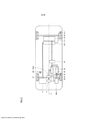
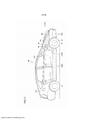
[0025] A Figura 1 é uma vista em perspectiva que mostra uma estrutura esquemática de um veículo híbrido, de acordo com uma modalidade.[0025] Figure 1 is a perspective view showing a schematic structure of a hybrid vehicle, according to an embodiment.
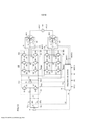
[0026] A Figura 2 é um diagrama em bloco que mostra a estrutura esquemática na Figura 1.[0026] Figure 2 is a block diagram showing the schematic structure in Figure 1.
[0027] A Figura 3 é uma vista em perspectiva que mostra a estru- tura esquemática de um corpo de uma unidade principal do veículo do veículo híbrido.[0027] Figure 3 is a perspective view showing the schematic structure of a body of a main unit of the hybrid vehicle vehicle.
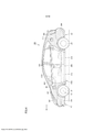
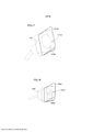
[0028] A Figura 4 é uma vista lateral do veículo híbrido.[0028] Figure 4 is a side view of the hybrid vehicle.
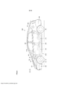
[0029] A Figura 5 é uma vista lateral que mostra uma primeira mo dificação do veículo híbrido, de acordo com a modalidade.[0029] Figure 5 is a side view showing a first modification of the hybrid vehicle, according to the modality.
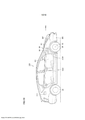
[0030] A Figura 6 é uma vista lateral que mostra uma segunda modificação do veículo híbrido, de acordo com a modalidade.[0030] Figure 6 is a side view showing a second modification of the hybrid vehicle, according to the modality.
[0031] A Figura 7 é uma vista lateral que mostra uma terceira mo dificação do veículo híbrido, de acordo com a modalidade.[0031] Figure 7 is a side view showing a third modification of the hybrid vehicle, according to the modality.
[0032] A Figura 8 é um diagrama em bloco que mostra um exem plo em que uma unidade de carga/fornecimento de energia e uma unidade de abastecimento são dispostas em uma superfície lateral em um lado de assento de motorista.[0032] Figure 8 is a block diagram showing an example where a charging/power supply unit and a supply unit are arranged on a side surface on a driver's seat side.
[0033] A Figura 9 é uma vista lateral que mostra uma quarta modi ficação do veículo híbrido, de acordo com a modalidade.[0033] Figure 9 is a side view showing a fourth modification of the hybrid vehicle, according to the modality.
[0034] A Figura 10 é uma vista lateral que mostra uma quinta mo dificação do veículo híbrido, de acordo com a modalidade.[0034] Figure 10 is a side view showing a fifth modification of the hybrid vehicle, according to the modality.
[0035] A Figura 11 é uma vista lateral que mostra uma sexta modi ficação do veículo híbrido, de acordo com a modalidade.[0035] Figure 11 is a side view showing a sixth modification of the hybrid vehicle, according to the modality.
[0036] A Figura 12 é um diagrama em bloco esquemático do veí culo híbrido, de acordo com a modalidade da invenção, e ilustra o for-necimento de energia externo.[0036] Figure 12 is a schematic block diagram of the hybrid vehicle, according to the embodiment of the invention, and illustrates the supply of external power.
[0037] A Figura 13 é um diagrama em bloco esquemático do veí culo híbrido, de acordo com a modalidade da invenção, e ilustra a carga de uma bateria.[0037] Figure 13 is a schematic block diagram of the hybrid vehicle, according to the embodiment of the invention, and illustrates the charging of a battery.
[0038] A Figura 14 é uma vista em perspectiva que mostra uma parte de um corpo de armação equipado.[0038] Figure 14 is a perspective view showing a part of an equipped frame body.
[0039] A Figura 15 é uma vista em planta que mostra uma arma ção do corpo de armação equipado mostrado na Figura 14.[0039] Figure 15 is a plan view showing a frame of the fitted frame body shown in Figure 14.
[0040] A Figura 16 é uma vista esquemática que mostra esquema- ticamente uma estrutura na qual a invenção é aplicada a um veículo a célula de combustível.[0040] Figure 16 is a schematic view that schematically shows a structure in which the invention is applied to a fuel cell vehicle.
[0041] A Figura 17 é uma vista em perspectiva que mostra as es truturas da e ao redor da unidade de conexão.[0041] Figure 17 is a perspective view showing the structures of and around the connection unit.
[0042] A Figura 18 é uma vista em perspectiva que mostra as es truturas da e ao redor da unidade de conexão.[0042] Figure 18 is a perspective view showing the structures of and around the connection unit.
[0043] As modalidades da invenção serão descritas agora com referência aos desenhos. Na descrição a seguir, as mesmas porções ou correspondentes usam as mesmas referências numéricas, e a descrição destas não é repetida.[0043] The embodiments of the invention will now be described with reference to the drawings. In the following description, the same or corresponding portions use the same numerical references, and the description of these is not repeated.
[0044] Referindo-se às Figuras 1 a 13, a descrição será fornecida em um veículo híbrido 100, de acordo com uma modalidade. A Figura 1 é uma vista em perspectiva que mostra uma estrutura esquemática do veículo híbrido 100, de acordo com a modalidade. A Figura 2 é um diagrama em bloco que mostra a estrutura esquemática na Figura 1. A Figura 3 é uma vista em perspectiva que mostra a estrutura esquemática de um corpo 500 de uma unidade principal do veículo 200 do veículo híbrido 100.[0044] Referring to Figures 1 to 13, the description will be provided on a
[0045] Referindo-se à Figura 1, o veículo híbrido 100 inclui a unidade principal do veículo 200 formada por um corpo e partes exteriores, um par de rodas dianteiras 2F disposto em um lado dianteiro em uma direção de funcionamento D do veículo híbrido 100, e rodas traseiras 2R dispostas em um lado traseiro na direção de funcionamento D.[0045] Referring to Figure 1, the
[0046] A unidade principal do veículo 200 inclui um compartimento de motor ER disposto na frente, na direção de funcionamento D, do veículo híbrido 100, um compartimento de acomodação de ocupante CR adjacente a um lado traseiro, na direção de funcionamento D, do compartimento de motor ER, e um compartimento de bagagem LR ad- jacente a um lado traseiro, na direção de funcionamento D, do compartimento de acomodação de ocupante CR.[0046] The main unit of the
[0047] Por exemplo, conforme mostrado na Figura 3, um corpo unificado é empregado como o corpo 500 da unidade principal do veículo 200. O corpo 500 inclui uma roda dianteira 550 que é disposta no lado dianteiro na direção de funcionamento D e define o compartimento de motor ER, uma parede de compartimento 560 que define o compartimento de acomodação de ocupante CR, e uma parede traseira 570 disposta em um lado traseiro, na direção de funcionamento D, da unidade principal do veículo 200.[0047] For example, as shown in Figure 3, a unified body is employed as the
[0048] A roda dianteira 550 inclui um braço dianteiro 501 que é disposto no lado dianteiro da unidade principal do veículo 200 e se estende em uma direção de largura da unidade principal do veículo 200, as paredes laterais dianteiras 504 que continuam até as extremidades opostas do braço dianteiro 501, respectivamente, e definem as porções superfície lateral do compartimento de motor ER, e uma divisão dianteira 510 disposta entre o compartimento de motor ER e o compartimento de acomodação de ocupante CR.[0048] The
[0049] Cada parede lateral dianteira 504 tem uma largura vertical que aumenta à medida que a posição se move a partir do braço dianteiro 501 em direção à divisão dianteira 510. A parede lateral dianteira 504 tem uma porção intermediária longitudinal que é curvada para aceitar a roda dianteira 2F.[0049] Each
[0050] A parede lateral dianteira 504 tem uma espessura que au menta à medida que a posição se move a partir do braço dianteiro 501 em direção à divisão dianteira 510.[0050] The
[0051] A parede de compartimento 560 inclui suportes dianteiros 503 que são dispostos nas porções laterais situadas nas extremidades opostas à direção da largura da divisão dianteira 510, respectivamente, e se estende em uma direção da altura da unidade principal do veí- culo 200, colunas dianteiras 507 conectada às extremidades superiores de suportes dianteiros 503, respectivamente, e sob suportes 505 conectados às extremidades inferiores de suportes dianteiros 503, respectivamente.[0051] The
[0052] O corpo 500 é proporcionado em suas superfícies laterais com aberturas 212L e 212R que continuam no compartimento de acomodação de ocupante CR para permitir a entrada de ocupantes. Cada uma das aberturas 212L e 212R tem uma periferia que é definida pelo suporte dianteiro 503, sob o suporte 505, a coluna dianteira 507 e uma borda da parede traseira 570.[0052] The
[0053] No corpo 500, uma porção situada à frente, na direção de funcionamento D, em relação ao compartimento de acomodação de ocupante CR tem uma espessura menor que uma porção situada para trás na direção de funcionamento D. Deste modo, quando a colisão frontal ocorre, um lado dianteiro do corpo 500 se deforma para absorver um impacto para proteger a parte interna do compartimento de acomodação de ocupante CR.[0053] In the
[0054] Uma pluralidade de partes exteriores é fixada à superfície de corpo 500 que tem a estrutura acima. Deste modo, a unidade principal do veículo 200 é formada.[0054] A plurality of outer parts are attached to the
[0055] As partes exteriores incluem, por exemplo, uma face dian teira 310 disposta no lado dianteiro da unidade principal do veículo 200 na Figura 1, um para-choque dianteiro 300 disposto sob a face dianteira 310, e para-lama dianteiro 301 que cobre as paredes laterais dianteiras 504 mostradas na Figura 3, assim como portas dianteira e traseira 312 e 313 para fechar as aberturas 212L e 212R.[0055] The outer parts include, for example, a
[0056] As partes exteriores também incluem um capô 307 que forma uma tampa superior do compartimento de motor ER, para-lama traseiro 303 disposto para trás, na direção de funcionamento D, em relação às portas traseiras 313, respectivamente, e um para-choque traseiro 304 disposto sob o para-lama traseiro 303.[0056] The exterior parts also include a
[0057] No compartimento de acomodação de ocupante CR, dis pôs-se um assento de motorista DR para operar o veículo híbrido 100, um assento de passageiro vizinho, na direção de largura do veículo híbrido 100, no assento de motorista, e assentos traseiros através do assento de passageiro e do assento de motorista DR. No exemplo mostrado na Figura 1, o assento de motorista DR é deslocado em direção à superfície lateral direita (uma das superfícies laterais) 100A do veículo híbrido 100 em relação a uma linha central O do veículo híbrido 100 que se estende na direção de funcionamento D.[0057] In the occupant accommodation compartment CR, a driver's seat DR for operating the
[0058] Conforme mostrado na Figura 1, um tanque de combustível 201 que armazena combustível líquido, tal como, gasolina é disposto sob os assentos traseiros no compartimento de acomodação de ocupante CR. Uma bateria (unidade de armazenamento de energia) B, tal como, uma célula de combustível ou um capacitor com uma grande capacidade é disposto para trás, na direção de funcionamento D, em relação aos assentos traseiros.[0058] As shown in Figure 1, a
[0059] O compartimento de motor ER acomoda um motor 4 de um motor de combustão interna que gera uma força motriz que aciona as rodas dianteiras 2F, assim como um eixo de transmissão (transaxle) TR.[0059] The ER engine compartment accommodates an
[0060] O eixo de transmissão TR inclui geradores de motor MG1 e MG2 rodas dianteiras de direção 2F, um conversor de reforço 20 que regula uma energia elétrica fornecida a partir da bateria B, inversores 30 e 40 que convertem a energia CC fornecida a partir do conversor de reforço 20 para uma energia CA e fornece a mesma para os geradores de motor MG1 e MG2, respectivamente, e um mecanismo de divisão de força 3 formada por uma engrenagem planetária e outras.[0060] The TR drive shaft includes engine generators MG1 and
[0061] O motor 4 é deslocado em direção à superfície lateral 100A em relação à linha central O, e o eixo de transmissão TR é deslocado em direção à superfície lateral 100B em relação à linha central O. Um centro de gravidade de uma combinação de motor 4 e eixo de transmissão TR se situa na ou próximo à linha central O para manter um equilíbrio na direção da largura do veículo híbrido 100.[0061] The
[0062] Ademais, um centro de gravidade de cada bateria B e tan que de combustível 201 se situa na ou próximo à linha central O.[0062] Furthermore, a center of gravity of each battery B and
[0063] Uma unidade de carga/fornecimento de energia (isto é, uni dade de entrada/saída de energia elétrica) 90 que é como uma unidade para carga elétrica e fornecimento de energia elétrica, assim como a unidade de abastecimento 213 são dispostos em uma superfície lateral do veículo híbrido 100 e, particularmente, na superfície lateral 100B oposta à superfície lateral 100A adjacente ao assento de motorista DR. Uma roda de direção, eixo de direção, engrenagem de direção, e similares, para dirigir as rodas dianteiras 2F são dispostos na ou próximo ao assento de motorista DR.[0063] A load/power supply unit (i.e., electric power input/output unit) 90 which is like a unit for electric load and electric power supply, as well as the
[0064] A unidade de carga/fornecimento de energia 90 e a unidade de abastecimento 213 mantêm um equilíbrio de peso em relação ao assento de motorista DR.[0064] The charging/
[0065] No exemplo mostrado na Figura 1, unidade de car- ga/fornecimento de energia 90 inclui uma unidade de conexão 91 que é disposta no corpo 500 e tem uma abertura para encaixar um conector 190 na mesma, uma tampa passível de abertura 90A que pode fechar uma abertura da unidade de conexão 91 e uma interconexão 92 conectada à unidade de conexão 91. O conector 190 inclui um conector de carga, um conector de fornecimento de energia elétrica ou um conector de carga/fornecimento de energia.[0065] In the example shown in Figure 1, charging/
[0066] O conector de carga é um conector para carregar a bateria B com uma energia elétrica fornecida a partir de uma energia comercial (por exemplo, de uma CA de 100V de fase única no Japão). Este conector de carga é, por exemplo, um soquete conectado a uma fonte de energia domiciliar geral.[0066] The charge connector is a connector for charging battery B with an electrical power supplied from a commercial power source (eg a single-phase 100V AC in Japan). This load connector is, for example, a socket connected to a general household power source.
[0067] A fonte de energia conector é um conector para fornecer uma energia elétrica (por exemplo, de uma CA de 100V de fase única no Japão) fornecida a partir do veículo híbrido 100 até uma carga externa. Ademais, o conector de carga/fornecimento de energia é um conector que tem ambas as funções do conector de carga e do conector descrito acima, pode carregar a bateria com a energia fornecida a partir da energia comercial e também fornecer a energia a partir do veículo híbrido 100 até a carga externa.[0067] The connector power supply is a connector to provide an electrical power (eg from a single-phase 100V AC in Japan) supplied from the
[0068] Um método de fornecer e receber a energia elétrica entre o conector 190 e a unidade de carga/fornecimento de energia 90 pode ser de um tipo de contato em que uma parte do conector 190 pode ficar em contato direto com pelo menos uma parte da unidade de car- ga/fornecimento de energia 90. Também, o mesmo pode ser de um tipo indutivo.[0068] A method of supplying and receiving electrical power between
[0069] A interconexão 92 é conectada a um ponto neutro entre os geradores de motor MG1 e MG2, e a energia fornecida a partir do conector 190 pode ser fornecida para a bateria B através dos geradores de motor MG1 e MG2, dos inversores 30 e 40 e do conversor de reforço 20.[0069]
[0070] Também, a unidade de carga/fornecimento de energia 90 pode fornecer externamente a energia armazenada na bateria B a partir do conector 190 através do conversor de reforço 20 e dos inversores 30 e 40.[0070] Also, the charging/
[0071] No exemplo mostrado na Figura 1, a unidade de abasteci mento 213 inclui um receptor de bocal 215 que é formado no corpo 500 e tem uma abertura, um tubo de abastecimento 214 conectado ao receptor de bocal 215 e ao tanque de combustível 201, e uma tampa passível de abertura 213A que é disposta em uma parte exterior para fechar uma abertura do receptor de bocal 215.[0071] In the example shown in Figure 1, the
[0072] O receptor de bocal 215 pode receber um bocal de abaste cimento do conector de abastecimento 191 disposto na parte externa do veículo híbrido 100. O combustível fornecido, tal como, gasolina flui através do tubo de abastecimento 214 para dentro do tanque de combustível 201.[0072] The
[0073] Uma vez que a unidade de abastecimento 213 e a unidade de carga/fornecimento de energia 90 são dispostas na mesma superfície lateral 100B do veículo híbrido 100, conforme descrito acima, um motorista pode lembrar as posições da unidade de carga/fornecimento de energia 90 e da unidade de abastecimento 213 sem dificuldade. Portanto, quando o motorista move o veículo híbrido 100 até o posto de carga/abastecimento ou similar, um erro sobre as direções de entrada e parada do veículo híbrido 100 pode ser reduzido.[0073] Since the fueling
[0074] A Figura 4 é uma vista lateral do veículo híbrido 100. Na Figura 4, a unidade de carga/fornecimento de energia 90 pode ser situada em qualquer posição na superfície lateral 100B do veículo híbrido 100. Por exemplo, a mesma pode se situar em qualquer posição em uma superfície lateral do para-choque traseiro 304, para-lama traseiro 303, porta traseira 313, porta dianteira 312, para-lama dianteiro 301, uma superfície lateral do para-choque dianteiro 300, uma coluna central 305, uma coluna dianteira 302 ou uma coluna inferior 306. Igualmente, a unidade de abastecimento 213 pode se situar em qualquer posição na superfície lateral 100B.[0074] Figure 4 is a side view of the
[0075] A unidade de carga/fornecimento de energia 90 pode ser disposta em uma região R1 da superfície lateral 100B que se situa para frente na direção de funcionamento D em relação à abertura 212L, ou em uma região R2 desta que se situa para trás na direção de funcionamento D em relação à abertura 212L. A unidade de abastecimento 213 pode ser disposta na região R1 ou R2 espaçada da unidade de carga/fornecimento de energia 90 com a abertura 212L entre estes.[0075] The load/
[0076] Deste modo, a abertura 212L se situa entre a unidade de carga/fornecimento de energia 90 e a unidade de abastecimento 213, de modo que a unidade de carga/fornecimento de energia 90 e a unidade de abastecimento 213 sejam espaçadas umas das outras na direção de funcionamento D. Portanto, é possível suprimir a confusão sobre a unidade de carga/fornecimento de energia 90 e a unidade de abastecimento 213 pelo motorista e similar.Thus, the
[0077] Uma vez que a unidade de carga/fornecimento de energia 90 é espaçada da unidade de abastecimento 213, um orifício que é formado no corpo 500 para encaixar a unidade de conexão 91 da unidade de car- ga/fornecimento de energia 90 no mesmo pode ser espaçado de um orifício no qual o receptor de bocal 215 da unidade de abastecimento 213 é encaixado, e é possível suprimir a formação de uma porção de maneira local que tem uma baixa rigidez no corpo 500.[0077] Since the charging/
[0078] No corpo 500, portanto, é possível suprimir a formação de uma porção que é sujeita a deteriorar ao longo do tempo. A região R1 inclui as superfícies laterais do para-lama dianteiro 301 e do para- choque dianteiro 300, e a região R2 inclui as superfícies laterais do para-lama traseiro 303 e do para-choque traseiro 304.[0078] In the
[0079] O receptor de bocal 215 da unidade de abastecimento 213 recebe o bocal de abastecimento do conector de abastecimento 191 encaixado no mesmo, e suporta o conector de abastecimento 191 através do bocal de abastecimento. O conector de abastecimento 191 tem de maneira geral e interna um mecanismo de regulação para regular uma velocidade ou taxa de abastecimento, e é mais pesado que o conector 190.The
[0080] A unidade de abastecimento 213 que suporta o conector de abastecimento pesado 191, conforme descrito acima tem rigidez maior que a unidade de conexão 91. Em particular, a unidade de abastecimento 213 suporta o tubo de abastecimento 214 e, portanto, deve ter maior rigidez que a unidade de conexão 91 conectada à interconexão 92.[0080] The
[0081] Consequentemente, a unidade de conexão 91 com menor rigidez se situa na região R1, e esta estrutura pode suprimir o aumento excessivo na rigidez do lado dianteiro do corpo 500 e pode assegurar uma função de absorção de impacto do corpo 500. Deste modo, a espessura do corpo 500 situada ao redor da unidade de car- ga/fornecimento de energia 90 é menor que a espessura da porção do corpo 500 situada ao redor da unidade de abastecimento 213.[0081] Consequently, the connecting
[0082] Ademais, reconheceu-se de maneira geral e ampla que a unidade de abastecimento 213 é disposta na superfície lateral 100B e, particularmente, atrás da abertura 212L. Ao dispor a unidade de abastecimento 213 atrás da abertura 212L, portanto, é possível suprimir o reconhecimento errôneo do motorista.[0082] Furthermore, it was generally and widely recognized that the
[0083] Conforme mostrado na Figura 1, o tanque de combustível 201 é disposto sob os assentos traseiros, e a unidade de abastecimento 213 se situa na região R2, de modo que o comprimento do tubo de abastecimento 214 possa ser reduzido.[0083] As shown in Figure 1, the
[0084] Ademais, conforme mostrado na Figura 1, os geradores de motor MG1 e MG2 são dispostos no compartimento de motor ER, e a unidade de carga/fornecimento de energia 90 é disposta na região R1, conforme mostrado na Figura 4, de modo que o comprimento da inter- conexão 92 possa ser reduzido.[0084] Furthermore, as shown in Figure 1, the MG1 and MG2 engine generators are arranged in the ER engine compartment, and the load/
[0085] De preferência, conforme mostrado na Figura 5, a unidade de carga/fornecimento de energia 90 é disposta em uma região R3 que se situa na superfície lateral 100B e, particularmente, se situa para trás na direção de funcionamento D, em relação a um eixo 53 conectado às rodas dianteiras 2F, e se situa para frente na direção de funcionamento D em relação à borda de abertura 212L. No corpo 500 mostrado na Figura 3, a parede lateral dianteira 504 que contém a região R3 tem a rigidez que aumenta à medida que a posição se move para trás na direção de funcionamento D e, portanto, tem a rigidez que permite substancialmente o suporte adequado da unidade de conexão 91 da unidade de carga/fornecimento de energia 90. Consequentemente, mesmo quando as operações de carga e fornecimento de energia externa são repetidas, a deterioração secular da parede lateral dianteira 504 pode ser suprimida.[0085] Preferably, as shown in Figure 5, the charging/
[0086] De preferência, conforme mostrado na Figura 6, a unidade de carga/fornecimento de energia 90 é disposta em uma região R4 que se situa na superfície lateral 100B e, particularmente, entre a borda de abertura da abertura 212L e a borda para frente (observada na direção de funcionamento D) da superfície lateral 100B e, mais particularmente, se situa acima de uma extremidade superior da roda dianteira 2F.[0086] Preferably, as shown in Figure 6, the charging/
[0087] Consequentemente, a unidade de carga/fornecimento de energia 90 pode ser situada em uma posição que permite o encaixe fácil do conector 190 mostrado na Figura 1, e as operações de carga e fornecimento de energia externa podem ser realizadas de maneira eficiente.[0087] Consequently, the charging/
[0088] De preferência, conforme mostrado na Figura 7, a unidade de carga/fornecimento de energia 90 é disposta em uma região R5 que se situa na superfície lateral 100B e, particularmente, se situa para frente na direção de funcionamento D em relação ao eixo 53. Ao dispor a unidade de carga/fornecimento de energia 90 na posição acima, é possível suprimir o contato entre a interconexão do conector 190 e a porta dianteira aberta 312 no estado em que a unidade de car- ga/fornecimento de energia 90 é encaixada no conector 190, mostrado na Figura 1.[0088] Preferably, as shown in Figure 7, the charging/
[0089] A Figura 8 é um diagrama em bloco que mostra um exem plo no qual a unidade de carga/fornecimento de energia 90 e a unidade de abastecimento 213 são dispostas na superfície lateral 100A no lado de assento de motorista DR. A Figura 9 é uma vista lateral que mostra um exemplo no qual a unidade de carga/fornecimento de energia 90 e a unidade de abastecimento 213 são dispostas na superfície lateral 100A no lado de assento de motorista DR.[0089] Figure 8 is a block diagram showing an example in which the charging/
[0090] Conforme mostrado na Figura 9, tanto a unidade de car- ga/fornecimento de energia 90 como a unidade de abastecimento 213 são dispostas na superfície lateral 100A e ficam próximas ao assento de motorista DR. Portanto, o motorista que saiu do assento de motorista DR para realizar a operação de carga e fornecimento de energia externa pode começar imediatamente a operação.[0090] As shown in Figure 9, both the charging/
[0091] A unidade de carga/fornecimento de energia 90 e a unidade de abastecimento 213 podem ser dispostas em qualquer posição na superfície lateral 100A.[0091] The charging/
[0092] No exemplo mostrado na Figura 9, a unidade de car- ga/fornecimento de energia 90 é disposta na superfície lateral 100A e, particularmente, em uma região R6 que se situa para frente, na direção de funcionamento D, em relação à borda de abertura da abertura 212R no lado de assento de motorista DR. A unidade de abastecimento 213 é disposta na superfície lateral 100A e, particularmente, em uma região R7 que se situa para trás, na direção de funcionamento D, em relação à borda de abertura da abertura 212R.[0092] In the example shown in Figure 9, the charging/
[0093] Conforme descrito acima, a abertura 212R se situa entre a unidade de carga/fornecimento de energia 90 e a unidade de abastecimento 213, de modo que a confusão sobre a unidade de car- ga/fornecimento de energia 90 e a unidade de abastecimento 213 possa ser suprimida, e o corpo 500 pode manter a função de absorção de impacto.[0093] As described above, the opening 212R is located between the charging/
[0094] No exemplo mostrado na Figura 10, a unidade de car- ga/fornecimento de energia 90 é disposta na superfície lateral 100A e, particularmente, em uma região R8 que se situa para trás, na direção de funcionamento D, em relação ao eixo 53 e se situa para trás, na direção de funcionamento D, em relação à borda de abertura da abertura 212R.[0094] In the example shown in Figure 10, the charging/
[0095] De maneira similar ao exemplo mostrado na Figura 5, este exemplo pode suprimir a deterioração secular da parede lateral dianteira 504, mesmo quando as operações de carga e fornecimento de energia externa são repetidas.[0095] Similar to the example shown in Figure 5, this example can suppress secular deterioration of the
[0096] No exemplo mostrado na Figura 11, a unidade de car- ga/fornecimento de energia 90 é disposta na superfície lateral 100A e, particularmente, em uma região R9 que se situa para trás, na direção de funcionamento D, em relação à borda de abertura da abertura 212R e se situa acima das rodas dianteiras 2F.[0096] In the example shown in Figure 11, the charging/
[0097] De maneira similar ao exemplo mostrado na Figura 6, este exemplo pode facilitar as operações de carga e fornecimento de energia externa e a operação de abastecimento.[0097] Similar to the example shown in Figure 6, this example can facilitate the operations of loading and supply of external energy and the supply operation.
[0098] A Figura 12 é um bloco esquemático do veículo híbrido 100, de acordo com a modalidade da invenção. Referindo-se à Figura 12, a descrição será fornecida em um método de carregar a bateria B com uma corrente CA fornecida a partir do conector 190.[0098] Figure 12 is a schematic block of the
[0099] Um eletrodo positivo da bateria B é conectado a uma linha positiva PL1, e um eletrodo negativo desta é conectado a uma linha negativa NL1. Um capacitor C1 é conectado entre as linhas positiva e negativa PL1 e NL1. O conversor de reforço 20 é conectado entre as linhas positiva e negativa PL1 e NL1 em uma lateral e as linhas positiva e negativa PL2 e NL2 na outra lateral. Um capacitor C2 é conectado entre as linhas positiva e negativa PL2 e NL2. O inversor 30 é conectado entre o gerador de motor MG1 e as linhas positiva e negativa PL2 e NL2. O inversor 40 é conectado entre o gerador de motor MG2 e as linhas positiva e negativa PL2 e NL2.[0099] A positive electrode from battery B is connected to a positive line PL1, and a negative electrode from this one is connected to a negative line NL1. A capacitor C1 is connected between positive and negative lines PL1 and NL1.
[00100] O gerador de motor MG1 inclui uma bobina trifásica 11, como uma bobina de estator, e o gerador de motor MG2 inclui uma bobina trifásica 12 como uma bobina de estator.[00100] The MG1 motor generator includes a three-
[00101] O conversor de reforço 20 inclui um reator L1, transistores NPN Q1 e Q2, e diodos D1 e D2. Uma extremidade do reator L1 é conectada à linha positiva PL1, e a outra extremidade é conectada a um ponto intermediário entre os transistores NPN Q1 e Q2, isto é, a um ponto entre um emissor do transistor NPN Q1 e um coletor do transistor NPN Q2. Os transistores NPN Q1 e Q2 são conectados em série entre a linha positiva PL1 e as linhas negativas NL1 e NL2. Um coletor de transistor NPN Q1 é conectado à linha positiva PL2 dos inversores 30 e 40, e um emissor do transistor NPN Q2 é conectado às linhas negativas NL1 e NL2. Os diodos D1 e D2 que são dispostos correspondem aos transistores NPN Q1 e Q2, respectivamente, e cada um é conectado entre o coletor e o emissor do transistor correspondente Q1 ou Q2 para passar uma corrente a partir do lado emissor até o lado coletor do mesmo.[00101] The
[00102] O inversor 30 é formado de braços de fase U, V e W 31, 32 e 33, que são conectados, paralelos uns aos outros, entre as linhas positiva e negativa PL2 e NL2.[00102] The
[00103] O braço de fase U 31 é formado de transistores NPN Q3 e Q4 conectados entre si em série. O braço de fase V 32 é formado de transistores NPN Q5 e Q6 conectados entre si em série. O braço de fase W 33 é formado de transistores NPN Q7 e Q8 conectados entre si em série. Os diodos D3 - D8 que são dispostos correspondem aos transistores NPN Q3 - Q8, respectivamente, e cada um é conectado entre um coletor e um emissor do transistor correspondente para passar a corrente a partir do lado emissor até o lado coletor.[00103] The
[00104] Um ponto intermediário de cada braço de fase do inversor 30 é conectado a uma extremidade de fase de cada bobina de fase de uma bobina trifásica 11 incluída no gerador de motor MG1. Deste modo, o gerador de motor MG1 é um motor de ímã permanente tri- fásico, e uma extremidade de cada uma das três, isto é, bobinas de fase U, V e W é comumente conectada a um ponto neutro M1. As outras extremidades das bobinas de fase U, V e W são conectadas aos pontos intermediários entre os transistores NPN Q3 e Q4, entre os transistores NPN Q5 e Q6, e entre os transistores NPN Q7 e Q8, respectivamente.[00104] A midpoint of each phase arm of
[00105] O inversor 40 é conectado, paralelo ao inversor 30, entre as extremidades opostas do capacitor C2. O inversor 40 é formado por braços de fase U, V e W 41, 42 e 43, que são conectados, paralelos uns aos outros, entre as linhas positiva e negativa PL2 e NL2.[00105]
[00106] O braço de fase U 41 é formado por transistores NPN Q9 e Q10 conectados entre si em série. O braço de fase V 42 é formado por transistores NPN Q11 e Q12 conectados entre si em série. O braço de fase W 43 é formado por transistores NPN Q13 e Q14 conectados entre si em série. Os transistores NPN Q9 - Q14 correspondem aos transistores NPN Q3 - Q8 do inversor 30, respectivamente. Deste modo, o inversor 40 tem a mesma estrutura que o inversor 30. Os diodos D9 - D14 que são dispostos correspondem aos transistores NPN Q9 - Q14, respectivamente, e cada um é conectado entre um coletor e um emissor de um transistor correspondente para passar a corrente a partir do lado emissor até o lado coletor.[00106] The
[00107] Um ponto intermediário de cada braço de fase do inversor 40 é conectado a uma extremidade de fase de cada bobina de fase de bobina trifásica 12 incluída no gerador de motor MG2. Deste modo, o gerador de motor MG2 é um motor de ímã permanente trifásico, e uma extremidade de cada uma das três, isto é, bobinas de fase U, V e W é comumente conectada ao ponto neutro M2. As outras extremidades das bobinas de fase U, V e W são conectadas aos pontos intermediários entre os transistores NPN Q9 e Q10, entre os transistores NPN Q11 e Q12, e entre os transistores NPN Q13 e Q14, respectivamente.[00107] A midpoint of each phase arm of
[00108] A bateria B é formada por uma bateria secundária, tal co- mo, uma bateria de níquel-hidrogênio ou uma bateria lítio-íon. Um sensor de tensão 10 capta uma tensão de bateria Vb proporcionada a partir da bateria B, e proporciona a tensão de bateria captada Vb para um dispositivo de controle 70. Os relés de sistema SR1 e SR2 são li- gados/desligados em resposta a um sinal SE a partir do dispositivo de controle 70. Mais especificamente, os relés de sistema SR1 e SR2 são ligados em resposta ao sinal SE em um nível H (nível de lógica elevado) a partir do dispositivo de controle 70, e são desligados em resposta ao sinal SE em um nível L (nível de lógica baixo) a partir do dispositivo de controle 70. O capacitor C1 suaviza a tensão CC fornecida a partir da bateria B, e fornece a tensão CC suavizada para o conversor de reforço 20.[00108] Battery B consists of a secondary battery, such as a nickel-hydrogen battery or a lithium-ion battery. A
[00109] O conversor de reforço 20 eleva a tensão CC fornecida a partir do capacitor C1, e fornece a mesma para o capacitor C2. Mais especificamente, quando o conversor de reforço 20 recebe um sinal PWC a partir do dispositivo de controle 70, o mesmo eleva e fornece a tensão CC para o capacitor C2 que corresponde a um período no qual o sinal PWC mantém o transistor Q2 ligado. Neste caso, o sinal PWC mantém o transistor NPN Q1 desligado. De acordo com o sinal PWC a partir do dispositivo de controle 70, o conversor de reforço 20 reduz a tensão CC fornecida a partir do inversor 30 e/ou 40 através do capacitor C2, e carrega a bateria B.[00109]
[00110] O capacitor C2 suaviza a tensão CC fornecida a partir do conversor de reforço 20, e fornece a tensão suavizada CC para os inversores 30 e 40. Um sensor de tensão 13 capta a tensão entre as extremidades opostas do capacitor C2, isto é, uma tensão de saída Vm do conversor de reforço 20 (que corresponde à tensão de entrada proporcionada para os inversores 30 e 40 (isto é verdadeiro na seguinte descrição)), e proporciona a voltagem de saída captada Vm para o dispositivo de controle 70.[00110] Capacitor C2 smoothes the DC voltage supplied from the
[00111] Quando o inversor 30 é dotado da tensão CC a partir do capacitor C2, o inversor 30 converte a tensão CC para a tensão CA com base em um sinal PWM1 dotado do dispositivo de controle 70, e aciona o gerador de motor MG1. Deste modo, o gerador de motor MG1 é acionado para gerar um torque indicado por um valor de comando de torque TR1. O inversor 30 converte a tensão CA que é gerada pelo gerador de motor MG1 durante a frenagem regenerativa do veículo híbrido equipado com o dispositivo de saída de energia para a tensão CC com base no sinal PWM1 proporcionado a partir do dispositivo de controle 70, e fornece a tensão convertida CC no conversor de reforço 20 através do capacitor C2. A frenagem regenerativa inclui a frenagem que é realizada quando o motorista do veículo híbrido opera um pedal de freio, e esta frenagem é acompanhada pela geração de energia regenerativa. Também, a frenagem regenerativa inclui a desaceleração (ou parada de aceleração) do veículo que não é realizada por uma operação de freio de pé, porém, é realizada ao liberar um pedal acelerador durante a execução enquanto causa a geração de energia regenerativa.[00111] When
[00112] O inversor 30 aciona o gerador de motor MG1, de acordo com o sinal PWM1 a partir do dispositivo de controle 70, de modo que uma tensão CA VAL para a energia comercial possa ser produzida a partir dos terminais 61 e 62 da unidade de carga/fornecimento de energia 90.[00112] The
[00113] Quando o inversor 40 é fornecido com a tensão CC do capacitor C2, o mesmo converte a tensão CC na tensão CA com base em um sinal PWM2 a partir do dispositivo de controle 70 para acionar o gerador de motor MG2. Deste modo, o gerador de motor MG2 é acionado para gerar um torque indicado por um valor de comando de torque TR2. Ademais, quando o veículo híbrido equipado com o dispositivo de saída de força motriz realiza a frenagem regenerativa, o inversor 40 converte a tensão CA gerada pelo gerador de motor MG2 na tensão CC com base no sinal PWM2 a partir do dispositivo de controle 70, e fornece a tensão convertida CC no conversor de reforço 20 através do capacitor C2.[00113] When
[00114] Ademais, o inversor 40 aciona o gerador de motor MG2, de acordo com o sinal PWM2 a partir do dispositivo de controle 70, de modo que a tensão CA VAC para a energia comercial possa ser produzida a partir dos terminais 61 e 62 da unidade de car- ga/fornecimento de energia 90.[00114] In addition, the
[00115] Um sensor de corrente 14 capta uma corrente de motor MCRT1 que flui através do gerador de motor MG1, e proporciona a corrente de motor captada MCRT1 no dispositivo de controle 70. Um sensor de corrente 15 capta uma corrente de motor MCRT2 que flui através do gerador de motor MG2, e proporciona a corrente de motor MCRT2 to dispositivo de controle 70.[00115] A
[00116] A unidade de carga/fornecimento de energia 90 inclui uma bobina primária 51 e uma bobina secundária 52. A bobina primária 51 é conectada entre o ponto neutro M1 da bobina trifásica 11 incluída no gerador de motor MG1 e o ponto neutro M2 da bobina trifásica 12 incluída no gerador de motor MG2. A unidade de carga/fornecimento de energia 90 converte a tensão CA que aparece entre os pontos neutros M1 e M2 dos geradores de motor MG1 e MG2 na tensão CA VAC para energia comercial, e produz a mesma a partir dos terminais 61 e 62.[00116] The load/
[00117] A Figura 13 é um diagrama em bloco esquemático do veículo híbrido 100 de acordo com a modalidade da invenção. Referindo- se à Figura 13, a descrição será fornecida em um método de fornecer a corrente CA para o conector 190 e fornecer externamente a energia elétrica. Referindo-se à Figura 13, seis transistores em cada um dos inversores 30 e 40 que é formado dos circuitos de ponte trifásica, respectivamente, podem conseguir estados ligado e desligado, cujos pa- drões de combinação são oito em número. Em dois destes oito padrões de comutação, uma tensão entre fase é zero, e este estado de tensão é referido como um vetor de tensão zero. No vetor de tensão zero, pode-se observar que todos os três transistores do braço superior encontram-se no mesmo estado de comutação (todos ligados ou todos desligados) e, também, pode-se observar que todos os três transistores do braço inferior encontram-se no mesmo estado de comutação. Portanto, a Figura 13 mostra os três transistores do braço superior do inversor 30 como um braço superior 30A e, também, mostra os três transistores do braço inferior do inversor 30 como um braço inferior 30B. Igualmente, a Figura 13 mostra os três transistores do braço superior do inversor 40 como um braço superior 40A e, também, mostra os três transistores do braço inferior do inversor 40 como um braço inferior 40B.[00117] Figure 13 is a schematic block diagram of the
[00118] Conforme mostrado na Figura 13, este circuito equivalente de fase zero pode ser observado como um conversor PWM de fase única cuja entrada é a energia de fase única CA proporcionada para os pontos neutros M1 e M2 através das linhas de entrada de energia ACL1 (92) e ACL2 (92) do conector 190. Consequentemente, o vetor de tensão zero é alterado em cada um dos inversores 30 e 40 para realizar o controle de comutação, de modo que os inversores 30 e 40 possam operar como os braços do conversor PWM de fase única. Deste modo, a energia CA proporcionada a partir das linhas de entrada de energia ACL1 e ACL2 pode ser convertida na energia CC, que é proporcionada para a linha positiva PL2. A energia CC convertida, deste modo, é fornecida para o conversor de reforço 20 através do capacitor C2 para carregar a bateria B.[00118] As shown in Figure 13, this zero-phase equivalent circuit can be viewed as a single-phase PWM converter whose input is single-phase AC power provided to neutral points M1 and M2 through the ACL1 power input lines (92) and ACL2 (92) of
[00119] Embora a modalidade tenha sido descrita em conexão com o caso em que a mesma é aplicada ao veículo híbrido que tem o corpo unificado, que não é restritivo. A Figura 14 é uma vista em perspectiva que mostra uma parte de um corpo de armação equipado 600, e a Figura 15 é uma vista em planta que mostra uma armação 650 do corpo de armação equipado 600 mostrado na Figura 14.[00119] Although the modality has been described in connection with the case in which it is applied to the hybrid vehicle that has the unified body, which is not restrictive. Figure 14 is a perspective view showing a portion of an equipped
[00120] No exemplo mostrado na Figura 14, o corpo de armação equipado 600 inclui a armação 650, e um corpo em formato de caixa 610 fixada a uma superfície superior da armação 650.[00120] In the example shown in Figure 14, the fitted
[00121] O Corpo 610 tem uma porção dianteira 630 que define o compartimento de motor ER. A porção dianteira 630 inclui uma porção de suporte superior 620 disposta em uma superfície dianteira, uma porção de suporte inferior 621, e porções de para-lama dianteiro 622 que definem as superfícies laterais do compartimento de motor ER.[00121]
[00122] As porções de borda superior da porção de suporte superior 620 e as porções de para-lama dianteiro 622 definem uma parte da abertura do compartimento de motor ER, e a porção de suporte inferior 621 é disposta sob a porção de suporte superior 620.[00122] The upper edge portions of the
[00123] A porção central da porção de suporte superior 620, as porções de borda superior das porções de para-lama dianteiro 622 e a porção central da porção de suporte inferior 621 têm as espessuras reduzidas, de modo que uma estrutura flexível de um peso reduzido seja implementada. Deste modo, esta estrutura pode suprimir o aumento na vibração de um painel de capô (não-mostrado).[00123] The central portion of the
[00124] A unidade de carga/fornecimento de energia 90 é disposta na porção de para-lama dianteiro 622 que tem a estrutura flexível. Deste modo, a provisão da unidade de carga/fornecimento de energia 90 pode suprimir o aumento na rigidez da porção de para-lama dianteiro 622 e, portanto, o aumento na vibração do painel de painel de capô até uma extensão mais alta, quando comparado com o caso em que a unidade de abastecimento 213 mostrada na Figura 1 é disposta no mesmo.[00124] The load/
[00125] Conforme mostrado na Figura 13, a armação 650 inclui um par de armações laterais 651 que se estende na direção de funcionamento D do veículo híbrido 100, uma pluralidade de porções de suporte lateral 652 - 660 disposta entre estas armações laterais 651, e uma pluralidade de porções de fixação 670 que fixam o corpo 610 e a armação 650 em conjunto. Uma vez que o corpo de armação equipado 600 inclui a armação 650 descrita acima, o mesmo pode assegurar a alta rigidez. Por exemplo, para uma operação de reboque, a armação 650 pode ser dotada de uma porção de reboque, de modo que a deformação ou similar do corpo de armação equipado 600 possa ser suprimida.[00125] As shown in Figure 13,
[00126] A modalidade foi descrita com base no autodenominado "híbrido paralelo em série" que é um certo tipo de híbrido. Entretanto, isto não é restritivo. Mais especificamente, a modalidade pode ser aplicada a um híbrido em série, isto é, um tipo híbrido no qual o veículo inclui um motor que é um motor de combustão interna que requer abastecimento, e um motor em funcionamento (isto é, motor para dirigir) que aciona as rodas através de uma energia elétrica gerada pelo motor e/ou por uma energia elétrica armazenada em uma bateria. Ademais, a modalidade pode ser aplicada a um híbrido paralelo em que ambos os motores podem proporcionar forças motrizes para um eixo de transmissão.[00126] The modality was described based on the so-called "parallel hybrid in series" which is a certain type of hybrid. However, this is not restrictive. More specifically, the modality can be applied to a series hybrid, i.e., a hybrid type in which the vehicle includes an engine that is an internal combustion engine that requires fueling, and a running engine (i.e., engine to drive ) that drives the wheels through electrical energy generated by the engine and/or electrical energy stored in a battery. Furthermore, the modality can be applied to a parallel hybrid in which both engines can provide driving forces to a drive shaft.
[00127] No veículo híbrido, de acordo com a modalidade, os métodos de utilização de neutros M1 e M2 de geradores de motor MG1 e MG2 são empregados como o método de carregar a bateria B e o método de fornecer externamente a energia elétrica. Entretanto, isto não é restritivo. Por exemplo, um dispositivo de carga/fornecimento de energia dedicado que tem as funções como um inversor e um conversor CC/CC podem ser empregados para realizar a carga e o fornecimento de energia elétrica. Este dispositivo de carga/fornecimento de energia dedicado é conectado, por exemplo, entre o capacitor C1 e os relés de sistema SR1 e SR2 na Figura 12.[00127] In the hybrid vehicle, according to the modality, the methods of using neutrals M1 and M2 of MG1 and MG2 engine generators are employed as the method of charging the battery B and the method of externally supplying electrical energy. However, this is not restrictive. For example, a dedicated charging/power supply device that has the functions of an inverter and a DC/DC converter can be employed to carry out the charging and supply of electrical energy. This dedicated charging/power supply device is connected, for example, between capacitor C1 and system relays SR1 and SR2 in Figure 12.
[00128] A modalidade foi descrita em conexão com um exemplo no qual a invenção é aplicada ao veículo híbrido, isto não é restritivo.[00128] The modality was described in connection with an example in which the invention is applied to the hybrid vehicle, this is not restrictive.
[00129] Por exemplo, a invenção pode ser aplicada em um veículo a célula de combustível.[00129] For example, the invention can be applied in a fuel cell vehicle.
[00130] A Figura 16 é uma vista esquemática que mostra esquematicamente uma estrutura na qual a invenção é aplicada em um veículo a célula de combustível 1000. Conforme mostrado na Figura 16, o veículo à célula de combustível 1000 inclui uma célula de combustível 1100, uma unidade de armazenamento de energia 1200, tal como, um capacitor, um inversor 1400 para execução, um inversor 1600 para acessórios, um motor adicional 1700 e uma ECU (Unidade de Controle Eletrônico) 1800. Um dispositivo de controle de um sistema elétrico, de acordo com a modalidade, é implementado, por exemplo, por programas executados pela ECU 1800.[00130] Figure 16 is a schematic view schematically showing a structure in which the invention is applied in a
[00131] A célula de combustível 1100 gera a energia elétrica através de uma reação química de hidrogênio e oxigênio no ar. A energia elétrica gerada pela célula de combustível 1100 é armazenada na unidade de armazenamento de energia 1200 ou é consumida por dispositivos montados no veículo à célula de combustível 1000. Uma vez que a célula de combustível 1100 pode empregar tecnologias gerais conhecidas, a descrição adicional destas não é repetida.[00131] The 1100 fuel cell generates electrical energy through a chemical reaction of hydrogen and oxygen in the air. The electrical energy generated by
[00132] A unidade de armazenamento de energia 1200 é formada, por exemplo, por uma pluralidade de células (capacitores elétricos de camada dupla) conectadas em série, e pode ser uma bateria secundária ou similar. O inversor 1400 para funcionamento converte a energia CC fornecida a partir da célula de combustível 1100 e a unidade de armazenamento de energia 1200 na energia CA, e aciona um motor em funcionamento 1500. Durante a frenagem regenerativa, a mesma converte a energia CA gerada pelo motor em funcionamento 1500 na energia CC, e fornece a mesma para a unidade de armazenamento de energia 1200.[00132] The
[00133] O motor em funcionamento 1500 é uma máquina dínamo- elétrica CA trifásica. As bobinas de fase U, V e W são enroladas ao redor de um estator do motor em funcionamento 1500. As extremidades em uma lateral das bobinas de fase U, V e W são conectadas entre si em um ponto neutro. As outras extremidades das bobinas de fase U, V e W são conectadas para executar o inversor 1400.[00133] The 1500 running motor is a three-phase AC dynamo-electric machine. The U, V and W phase coils are wound around a 1500 running motor stator. The ends on one side of the U, V and W phase coils are connected together at a neutral point. The other ends of the U, V, and W phase coils are connected to run the 1400 inverter.
[00134] Uma interconexão 1192B de uma unidade de conexão (segunda unidade de conexão) 1090 é conectada ao ponto neutro do motor em funcionamento 1500. Nesta unidade de conexão 1090, é possível conectar, por exemplo, um conector 1190 conectado à fonte de energia CA, tal como, um conector de fonte de energia domiciliar geral. Portanto, a energia CA pode ser fornecida para o motor em funcionamento 1500.[00134] An
[00135] O motor adicional 1700 é igualmente uma máquina dínamo- elétrica CA trifásica. As bobinas de fase U, V e W são enroladas ao redor de um estator do motor adicional 1700. As extremidades em uma lateral das bobinas de fase U, V e W destas são conectadas entre si em um ponto neutro. As outras extremidades das bobinas de fase U, V e W são conectadas ao inversor adicional 1600.[00135] The
[00136] Uma interconexão 1192A da unidade de conexão 1090 é conectada ao ponto neutro do motor adicional 1700, de modo que a energia CA possa ser fornecida a um ponto neutro do motor adicional 1700 a partir da unidade de conexão 1090 a partir do conector 1190 através da unidade de conexão 1090.[00136] An
[00137] A unidade de conexão 1090 descrita acima é disposta em uma superfície lateral 100A do veículo à célula de combustível 1000.[00137] The
[00138] Conforme descrito acima, a energia CA fornecida para o motor em funcionamento 1500 e para o motor adicional 1700 é conver- tida na energia CC ao executar o inversor 1400 e o inversor adicional 1600, e é fornecida para a unidade de armazenamento de energia 1200, de modo que a unidade de armazenamento de energia 1200 seja carregada.[00138] As described above, the AC power supplied to the running
[00139] A força motriz fornecida a partir do motor em funcionamento 1500 aciona o veículo à célula de combustível 1000 para funcionar. Na operação de frenagem regenerativa, as rodas (não mostradas) acionam o motor em funcionamento 1500 para operar como um gerador de energia elétrica. Deste modo, o motor em funcionamento 1500 opera como um freio regenerativo que converte a energia de frenagem na energia elétrica.[00139] Motive power supplied from the running
[00140] O inversor adicional 1600 converte a energia CC fornecida a partir da célula de combustível 1100 e da unidade de armazenamento de energia 1200 até a energia CA, e aciona o motor adicional 1700. O motor adicional 1700 aciona os acessórios que operam para operar a célula de combustível 1100. Os acessórios que são acionados para operar a célula de combustível 1100 serão posteriormente descritos.[00140]
[00141] Um voltímetro 1802 e um comutador de partida 1804 são conectados a ECU 1800. O voltímetro capta uma tensão de sistema (isto é, uma tensão da unidade de armazenamento de energia 1200), e transmite um sinal que indica um resultado da captação na ECU 1800. Um motorista do veículo à célula de combustível 1000 pode operar o comutador de partida 1804. Quando o comutador de partida 1804 é ligado, a ECU 1800 inicia o sistema do veículo. Quando o comutador de partida 1804 é desligado, a ECU 1800 interrompe o sistema do veículo.[00141] An 1802 voltmeter and an 1804 start switch are connected to an
[00142] A ECU 1800 controla os dispositivos e similares montados no veículo à célula de combustível 1000 para ajustar o veículo em um estado de acionamento desejado baseado em um estado de acionamento do veículo, uma posição de acelerador captada por um sensor de posição de acelerador (não mostrado), um grau de pressão descendente de um pedal de freio, uma posição de deslocamento, uma tensão de unidade de armazenamento de energia 1200 e um estado operado do comutador de partida 1804, assim como mapas e programas armazenados em uma ROM (Memória Somente de Leitura).[00142] The
[00143] O veículo à célula de combustível 1000 inclui um tanque de hidrogênio 1102, uma bomba de hidrogênio 1104, um filtro de ar 1106, uma bomba de ar 1108, um umidificador 1110, uma bomba d'água 1112 e um diluidor 1114.[00143] The
[00144] O tanque de hidrogênio 1102 armazena hidrogênio. Uma liga de armazenamento de hidrogênio pode ser usada em vez do tanque de hidrogênio 1102. O tanque de hidrogênio 1102 é conectado a uma unidade de conexão 1213 que fornece ao tanque de hidrogênio 1102 o hidrogênio fornecido a partir de uma unidade de conexão de fornecimento de hidrogênio 1191.[00144] The 1102 hydrogen tank stores hydrogen. A hydrogen storage alloy can be used in place of the 1102 hydrogen tank. The 1102 hydrogen tank is connected to a 1213 connection unit which supplies the 1102 hydrogen tank with hydrogen supplied from a supply connection unit.
[00145] Uma vez que as unidades de conexão 1213 e 1090 são dispostas na superfície lateral 100A, a confusão sobre as superfícies laterais onde as unidades de conexão 1213 e 1090 são dispostas pode ser suprimida quando o motorista realiza a operação de carga ou a operação de fornecimento de hidrogênio.[00145] Since the
[00146] Particularmente, uma vez que as unidades de conexão 1213 e 1090 são dispostas na mesma superfície lateral 100A, é possível suprimir um erro sobre a direção de entrada quando o motorista move o veículo até a estação de carga/fornecimento de hidrogênio.[00146] Particularly, since the
[00147] Ademais, ao espaçar as unidades de conexão 1213 e 1090 umas das outras na direção longitudinal do veículo, conforme mostrado na Figura 11, é possível suprimir a fratura frágil por hidrogênio que pode ocorrer na e ao redor da unidade de conexão 1090 devido ao hidrogênio fornecido a partir da unidade de conexão de fornecimento de energia 1191.[00147] Furthermore, by spacing the
[00148] Por exemplo, a abertura que continua no compartimento de acomodação de ocupante e permite a entrada de um ocupante se situa entre as unidades de conexão 1213 e 1090. Esta estrutura pode suprimir a fratura frágil por hidrogênio na e ao redor da unidade de conexão 1090, e também pode suprimir a confusão sobre as unidades de conexão 1213 e 1090 através de um operador.[00148] For example, the opening that continues into the occupant accommodation compartment and allows entry for an occupant is located between
[00149] A relação posicional entre a unidade de carga/fornecimento de energia 90 e a porção de conexão 1213 na primeira modalidade pode ser aplicada às unidades de conexão 1213 e 1090.[00149] The positional relationship between the load/
[00150] A Figura 17 é uma vista em perspectiva que mostra as estruturas da e ao redor da unidade de conexão 1213. Conforme mostrado na Figura 17, a unidade de conexão 1213 é acomodada em uma câmara de acomodação 1213C formada na superfície lateral 100A do veículo. A câmara de acomodação 1213C tem uma abertura externa 1213B, que pode ser fechada por uma tampa passível de abertura 1213A disposta de maneira articulada na superfície lateral 100A. A unidade de conexão 1213 pode aceitar a unidade de bocal da unidade de conexão de fornecimento de hidrogênio 1191. Para fornecer o hidrogênio para o veículo, um operador abre a tampa 1213A, encaixa a unidade de conexão de fornecimento de hidrogênio 1191 na unidade de conexão 1213 e inicia o fornecimento de hidrogênio. Quando o fornecimento de hidrogênio é concluído, a abertura da unidade de conexão 1213 é fechada por uma tampa interna passível de abertura (não mostrada), e a abertura 1213B é fechada pela tampa 1213A.[00150] Figure 17 is a perspective view showing the structures of and around the
[00151] Uma vez que a unidade de conexão 1213 é acomodada na câmara de acomodação passível de fechamento 1213C, conforme descrito acima, o vazamento externo do hidrogênio pode ser suprimido e é possível suprimir a corrosão do corpo de veículo que pode ocorrer em uma porção ao redor da câmara de acomodação 1213C devido ao hidrogênio.[00151] Since the
[00152] A Figura 18 é uma vista em perspectiva que mostra as estruturas da e ao redor da unidade de conexão 1090. Conforme mostrado na Figura 18, a unidade de conexão 1090 é acomodada em uma câmara de acomodação 1090C que é independente da câmara de acomodação 1213C.[00152] Figure 18 is a perspective view showing the structures of and around the 1090 connection unit. As shown in Figure 18, the 1090 connection unit is accommodated in a 1090C accommodation chamber that is independent of the housing chamber.
[00153] Portanto, o contato da unidade de conexão 1090 com o hidrogênio pode ser suprimido, e a corrosão da unidade de conexão 1090 pode ser suprimida.[00153] Therefore, the contact of the 1090 connection unit with hydrogen can be suppressed, and the corrosion of the 1090 connection unit can be suppressed.
[00154] Particularmente, quando uma abertura 1212 está presente entre as unidades de conexão 1090 e 1213, uma distância apropriada é mantida entre as unidades de conexão 1090 e 1213, e o contato de hidrogênio com a unidade de conexão 1090 pode ser suprimido.[00154] Particularly, when an opening 1212 is present between connecting
[00155] Para gerar a energia elétrica através da célula de combustível 1100, nesta modalidade, a bomba de hidrogênio 1104 alimenta o hidrogênio armazenado no tanque de hidrogênio 1102 em um lado de anodo da célula de combustível 1100. Para interromper a geração de energia da célula de combustível 1100, a bomba de hidrogênio 1104 é acionada para realizar um processo de interrupção de descarga de hidrogênio residual a partir do lado de anodo da célula de combustível 1100. O motor adicional 1700 aciona a bomba de hidrogênio 1104.[00155] To generate electrical energy through the
[00156] A bomba de ar 1108 alimenta o ar no lado de cátodo da célula de combustível 1100. Na geração de energia da célula de combustível 1100, a bomba de ar 1108 é acionada para captar o ar através do filtro de ar 1106, e o ar é umidificado pelo umidificador 1110 e, então, é alimentado em direção ao cátodo da célula de combustível 1100. Quando a geração da célula de combustível 1100 estiver para ser interrompida, a bomba de ar 1108 é acionada. Deste modo, o ar captado através do filtro de ar 1106 é alimentado em direção ao cátodo da célula de combustível 1100 sem ser umidificado, e o processo de interrupção de secagem da célula de combustível 1100 é realizado. A bomba de ar 1108 é acionada pelo motor adicional 1700.[00156]
[00157] A bomba d'água 1112 descarrega a água de resfriamento para resfriar a célula de combustível 1100. A água de resfriamento descarregada pela bomba d'água 1112 circula na célula de combustível 1100. A bomba d'água 1112 é acionada pelo motor adicional 1700.[00157] The 1112 water pump discharges the cooling water to cool the 1100 fuel cell. The cooling water discharged by the 1112 water pump circulates in the 1100 fuel cell. The 1112 water pump is driven by the engine additional 1700.
[00158] O hidrogênio passado através do lado de anodo da célula de combustível 1100 e o ar passado através do lado de cátodo são conduzidos até o diluidor 1114. O diluidor 1114 dilui o hidrogênio e o hidrogênio diluído é externamente descarregado a partir do veículo.[00158] The hydrogen passed through the anode side of the 1100 fuel cell and the air passed through the cathode side are led to the 1114 thinner. The 1114 thinner dilutes the hydrogen and the diluted hydrogen is externally discharged from the vehicle.
[00159] Embora apenas o motor adicional 1700 tenha sido descrito, os motores adicionais 1700 que são proporcionados correspondem à bomba de hidrogênio 1104, à bomba de ar 1108 e à bomba d'água 1112, respectivamente. Nesta modalidade, o motor adicional 1700 é acionado ao converter a energia elétrica fornecida a partir da unidade de armazenamento de energia 1200 a partir da energia CC até a energia CA. Entretanto, uma configuração que aciona o motor adicional 1700 através da energia CC sem usar o inversor adicional 1600 pode ser empregada.[00159] Although only the additional 1700 engine has been described, the additional 1700 engines that are provided correspond to the 1104 hydrogen pump, the 1108 air pump, and the 1112 water pump, respectively. In this mode, the
[00160] Na segunda modalidade, o hidrogênio usado na célula de combustível 1100 é fornecido através da unidade de conexão 1213. Entretanto, isto não é restritivo.[00160] In the second mode, the hydrogen used in
[00161] Por exemplo, em um sistema que emprega um reformador que retira o hidrogênio do combustível, tais como, átomos de hidrogênio contendo etanol, a unidade de conexão 1213 é abastecida com o metanol. A unidade de conexão 1213 é conectada a um tanque de metanol (não mostrado) empregado independentemente do tanque de hidrogênio 1102, e o tanque de metanol armazena o metanol.[00161] For example, in a system employing a reformer that removes hydrogen from the fuel, such as hydrogen atoms containing ethanol, the
[00162] O hidrogênio é produzido ao fornecer o metanol no tanque de metanol e a água ao reformador, e é armazenado no tanque de hidrogênio 1102. De maneira alternativa, uma configuração que fornece o hidrogênio produzido diretamente para a célula de combustível pode ser empregada.[00162] Hydrogen is produced by supplying methanol to the methanol tank and water to the reformer, and is stored in the 1102 hydrogen tank. Alternatively, a configuration that supplies the produced hydrogen directly to the fuel cell can be employed .
[00163] No sistema de metanol direto que fornece diretamente o metanol para a célula de combustível, a unidade de conexão é igualmente abastecida com o metanol.[00163] In the direct methanol system that directly supplies the methanol to the fuel cell, the connection unit is also supplied with methanol.
[00164] Neste sistema de metanol direto, o metanol é fornecido junto com a água para outro anodo da célula de combustível 1100, e é decomposto para produzir os íons de hidrogênio, elétrons e dióxido de carbono, usando um catalisador, tal como, platina. Os íons de hidrogênio se movem através de uma membrana eletrolítica em direção ao cátodo, e reage com o oxigênio no ar para se transformar em água. Os elétrons são fornecidos como uma energia elétrica através de terminais.[00164] In this direct methanol system, methanol is supplied along with water to another
[00165] No veículo à célula de combustível 1000 deste sistema de metanol direto, um tanque de metanol conectado à unidade de conexão 1213 armazena o metanol fornecido a partir da unidade de conexão 1213. O metanol armazenado no tanque de metanol é fornecido para a célula de combustível 1100.[00165] In the 1000 fuel cell vehicle of this direct methanol system, a methanol tank connected to the
[00166] Ademais, no veículo à célula de combustível 1000 equipado com um dispositivo de reforma de etanol, a unidade de conexão 1213 é abastecida com o etanol. Neste veículo à célula de combustível 1000 equipado com o dispositivo de reforma de etanol, o dispositivo de reforma de etanol é abastecido com o etanol e a água para produzir o hidrogênio e o dióxido de carbono. O hidrogênio produzido deste modo é fornecido para a célula de combustível para obter a energia elétrica.[00166] Furthermore, in
[00167] O veículo à célula de combustível 1000 equipado com o dispositivo de reforma de etanol é abastecido com o etanol através da unidade de conexão 1213, e armazena o mesmo no tanque de etanol. O etanol armazenado no tanque de etanol é fornecido para o dispositivo de reforma de etanol.[00167] The
[00168] Conforme descrito acima, a invenção pode ser aplicada a diversos tipos de veículos à célula de combustível 1000. Embora a terceira modalidade tenha sido descrita em conexão com o veículo à célula de combustível em que a unidade de armazenamento de energia 1200 é carregável e o combustível diferente da energia elétrica pode ser fornecido, isto não é restritivo.[00168] As described above, the invention can be applied to various types of vehicles to the
[00169] Por exemplo, a invenção pode ser aplicada ao veículo à célula de combustível no qual a energia CC armazenada na unidade de armazenamento de energia 1200 pode ser convertida na energia CA, e pode ser fornecida para uma carga externa, e o combustível diferente da energia elétrica pode ser fornecido para a célula de combustível para gerar uma força motriz.[00169] For example, the invention can be applied to the vehicle to the fuel cell in which the DC energy stored in the
[00170] Embora a presente invenção tenha sido descrita e ilustrada em detalhes, entende-se claramente que o mesmo ocorre apenas por meio de ilustração e exemplo e não deve ser considerada por meio de limitação, sendo que o escopo da presente invenção é interpretado através dos termos das reivindicações em anexo.[00170] Although the present invention has been described and illustrated in detail, it is clearly understood that it occurs only by way of illustration and example and should not be considered by way of limitation, and the scope of the present invention is interpreted through of the terms of the appended claims.
[00171] A invenção refere-se ao veículo híbrido e, particularmente, é adequada ao veículo híbrido que permite o fornecimento de energia elétrica e/ou o fornecimento de energia elétrica externa.[00171] The invention relates to the hybrid vehicle and, particularly, is suitable for the hybrid vehicle that allows the supply of electrical energy and/or the supply of external electrical energy.
Claims (6)
Applications Claiming Priority (4)
| Application Number | Priority Date | Filing Date | Title |
|---|---|---|---|
| JP2007-000113 | 2007-01-04 | ||
| JP2007000113 | 2007-01-04 | ||
| PCT/JP2007/075437 WO2008082012A1 (en) | 2007-01-04 | 2007-12-28 | Hybrid vehicle and vehicle |
| BRPI0720891A BRPI0720891B1 (en) | 2007-01-04 | 2007-12-28 | hybrid vehicle |
Publications (1)
| Publication Number | Publication Date |
|---|---|
| BR122019013049B1 true BR122019013049B1 (en) | 2021-08-10 |
Family
ID=39588669
Family Applications (2)
| Application Number | Title | Priority Date | Filing Date |
|---|---|---|---|
| BR122019013049-3A BR122019013049B1 (en) | 2007-01-04 | 2007-12-28 | ENERGY INPUT ARRANGEMENT IN A HYBRID VEHICLE |
| BRPI0720891A BRPI0720891B1 (en) | 2007-01-04 | 2007-12-28 | hybrid vehicle |
Family Applications After (1)
| Application Number | Title | Priority Date | Filing Date |
|---|---|---|---|
| BRPI0720891A BRPI0720891B1 (en) | 2007-01-04 | 2007-12-28 | hybrid vehicle |
Country Status (9)
| Country | Link |
|---|---|
| US (1) | US20100038156A1 (en) |
| EP (2) | EP2116405B1 (en) |
| JP (1) | JP4873016B2 (en) |
| KR (2) | KR20090096647A (en) |
| CN (2) | CN102700396B (en) |
| BR (2) | BR122019013049B1 (en) |
| IN (1) | IN2015DN04183A (en) |
| RU (1) | RU2424918C2 (en) |
| WO (1) | WO2008082012A1 (en) |
Families Citing this family (31)
| Publication number | Priority date | Publication date | Assignee | Title |
|---|---|---|---|---|
| JP4679891B2 (en) * | 2004-11-30 | 2011-05-11 | トヨタ自動車株式会社 | AC voltage generator and power output device |
| JP5078119B2 (en) * | 2005-12-06 | 2012-11-21 | トヨタ自動車株式会社 | Charger |
| JP4862745B2 (en) * | 2007-05-24 | 2012-01-25 | トヨタ自動車株式会社 | Vehicle control device, control method, program for realizing the method, and recording medium recording the program |
| WO2009028520A1 (en) | 2007-08-24 | 2009-03-05 | Toyota Jidosha Kabushiki Kaisha | Vehicle |
| JP4306776B2 (en) * | 2007-09-06 | 2009-08-05 | トヨタ自動車株式会社 | Hybrid vehicle |
| JP4577413B2 (en) * | 2008-06-20 | 2010-11-10 | トヨタ自動車株式会社 | vehicle |
| JP5018837B2 (en) * | 2009-07-17 | 2012-09-05 | 日産自動車株式会社 | Electric vehicle mounting structure |
| JP4915447B2 (en) * | 2009-12-25 | 2012-04-11 | トヨタ自動車株式会社 | Battery mounting structure for vehicle |
| JP2011148484A (en) * | 2009-12-26 | 2011-08-04 | Honda Motor Co Ltd | Power source system |
| JP5585363B2 (en) | 2010-10-01 | 2014-09-10 | 日産自動車株式会社 | Charging port cover arrangement structure |
| DE102010053137A1 (en) * | 2010-12-01 | 2012-06-06 | Volkswagen Ag | Charging interface for an electric vehicle |
| FR2980142B1 (en) | 2011-09-20 | 2013-10-18 | Peugeot Citroen Automobiles Sa | HYBRID VEHICLE COMPRISING TRAPPERS FOR RECHARGING WITH SELECTIVE OPENINGS |
| KR101302407B1 (en) * | 2011-10-14 | 2013-09-02 | 대동공업주식회사 | Electric vehicle for agriculture |
| JP5842567B2 (en) * | 2011-11-21 | 2016-01-13 | マツダ株式会社 | Vehicle electrical component arrangement structure |
| FR2985466B1 (en) | 2012-01-06 | 2014-01-24 | Peugeot Citroen Automobiles Sa | IMPROVED HEADREST FOR VEHICLE SEAT |
| EP2647523A1 (en) | 2012-04-04 | 2013-10-09 | Volvo Car Corporation | Circuit for charging a battery and for driving a three-phase electrical machine |
| JP5831343B2 (en) * | 2012-04-18 | 2015-12-09 | トヨタ自動車株式会社 | Mounting structure of an inverter for external power feeding of a vehicle equipped with a power supply device |
| JP5896145B2 (en) * | 2012-04-27 | 2016-03-30 | マツダ株式会社 | Vehicle power supply system |
| JP5935989B2 (en) * | 2012-04-27 | 2016-06-15 | マツダ株式会社 | Vehicle power supply system |
| KR20150006874A (en) * | 2012-05-09 | 2015-01-19 | 도요타지도샤가부시키가이샤 | Vehicle |
| WO2013187178A1 (en) * | 2012-06-14 | 2013-12-19 | ソニー株式会社 | Electric moving body, power transmission and reception system, and power reception method for electric moving body |
| JP5590073B2 (en) * | 2012-06-21 | 2014-09-17 | トヨタ自動車株式会社 | Vehicle power control device |
| CN104002652A (en) * | 2013-02-21 | 2014-08-27 | 王克锋 | Vehicle coupling driving system |
| JP5880500B2 (en) * | 2013-08-29 | 2016-03-09 | トヨタ自動車株式会社 | vehicle |
| JP6571548B2 (en) * | 2016-01-22 | 2019-09-04 | 株式会社シマノ | Fishing reel |
| KR20170134270A (en) * | 2016-05-27 | 2017-12-06 | 신흥에스이씨주식회사 | Battery pack for electric vehicle with excellent vibration-resistance |
| JP2018129956A (en) * | 2017-02-09 | 2018-08-16 | いすゞ自動車株式会社 | Vehicle charger |
| US20190360426A1 (en) * | 2018-05-24 | 2019-11-28 | GM Global Technology Operations LLC | Cylinder liners comprising induction coils and hybrid internal combustion engines and powertrains utilizing the same |
| JP7070249B2 (en) * | 2018-08-28 | 2022-05-18 | トヨタ自動車株式会社 | Vehicle power unit structure |
| JP7052673B2 (en) * | 2018-10-29 | 2022-04-12 | トヨタ自動車株式会社 | Electric vehicle |
| JP2023000567A (en) * | 2021-06-18 | 2023-01-04 | トヨタ自動車株式会社 | Power supply unit and vehicle |
Family Cites Families (27)
| Publication number | Priority date | Publication date | Assignee | Title |
|---|---|---|---|---|
| SE7300890L (en) * | 1973-01-23 | 1974-07-24 | ||
| US4218644A (en) * | 1978-09-19 | 1980-08-19 | Gould Inc. | Time controlled battery charger |
| US5099186A (en) * | 1990-12-31 | 1992-03-24 | General Motors Inc. | Integrated motor drive and recharge system |
| JPH04334906A (en) * | 1991-05-08 | 1992-11-24 | Honda Motor Co Ltd | Electric motor vehicle with auxiliary power source |
| JPH04334907A (en) * | 1991-05-08 | 1992-11-24 | Honda Motor Co Ltd | Charger for electric motor vehicle |
| US5202617A (en) * | 1991-10-15 | 1993-04-13 | Norvik Technologies Inc. | Charging station for electric vehicles |
| JPH08154307A (en) | 1994-11-29 | 1996-06-11 | Mitsubishi Motors Corp | Limited fuel use hybrid electric vehicle |
| US5858568A (en) * | 1996-09-19 | 1999-01-12 | Ztek Corporation | Fuel cell power supply system |
| JPH10136510A (en) * | 1996-11-01 | 1998-05-22 | Kojima Press Co Ltd | Charger in electric car |
| JP3673863B2 (en) * | 1997-09-30 | 2005-07-20 | 富士重工業株式会社 | Hybrid vehicle drive system |
| JPH11318004A (en) | 1998-05-07 | 1999-11-16 | Nissan Motor Co Ltd | Charging lid automatic operation device of electric vehicle |
| JP2001105903A (en) * | 1999-08-03 | 2001-04-17 | Toyota Motor Corp | Moving body, fuel supply device and fuel supply system |
| KR100325731B1 (en) * | 1999-08-24 | 2002-03-06 | 류정열 | Sliding door locking device for vehicle |
| JP4788018B2 (en) * | 2000-06-08 | 2011-10-05 | トヨタ自動車株式会社 | Fuel cell fuel supply system and moving body |
| US6378638B1 (en) * | 2001-03-14 | 2002-04-30 | New Venture Gear, Inc. | Drive axle for hybrid vehicle |
| US20030008183A1 (en) * | 2001-06-15 | 2003-01-09 | Ztek Corporation | Zero/low emission and co-production energy supply station |
| US6691749B2 (en) * | 2002-01-10 | 2004-02-17 | General Hydrogen Corporation | Service coupling |
| JP3999099B2 (en) * | 2002-10-29 | 2007-10-31 | 本田技研工業株式会社 | Fuel lid opener mechanism |
| JP4037242B2 (en) * | 2002-10-30 | 2008-01-23 | 本田技研工業株式会社 | Gaseous fuel filling system |
| CA2447238C (en) * | 2002-10-29 | 2007-03-20 | Honda Motor Co.,Ltd. | Fuel gas filling system |
| JP4438417B2 (en) | 2004-01-13 | 2010-03-24 | トヨタ自動車株式会社 | AC voltage generator and power output device |
| US20060241524A1 (en) * | 2005-03-11 | 2006-10-26 | Qi Yu | Intravascular ultrasound catheter device and method for ablating atheroma |
| KR20080003905A (en) * | 2005-05-05 | 2008-01-08 | 에이에프에스 트리니티 파워 코포레이션 | Plug-in hybrid vehicle with fast energy storage |
| US7451839B2 (en) * | 2005-05-24 | 2008-11-18 | Rearden, Llc | System and method for powering a vehicle using radio frequency generators |
| JP4752352B2 (en) * | 2005-06-24 | 2011-08-17 | トヨタ自動車株式会社 | AC voltage output device and hybrid vehicle equipped with the same |
| JP2008049869A (en) * | 2006-08-25 | 2008-03-06 | Toyota Motor Corp | Receptacle |
| CN101011931A (en) * | 2007-01-30 | 2007-08-08 | 重庆大学 | Drive system and drive method of ISG type whole wheel driven hybrid power automobile |
-
2007
- 2007-12-28 CN CN201210217806.7A patent/CN102700396B/en not_active Expired - Fee Related
- 2007-12-28 KR KR1020097016256A patent/KR20090096647A/en not_active Application Discontinuation
- 2007-12-28 JP JP2008552202A patent/JP4873016B2/en active Active
- 2007-12-28 CN CN200780049094XA patent/CN101573246B/en not_active Expired - Fee Related
- 2007-12-28 KR KR1020117031616A patent/KR20120006094A/en not_active Application Discontinuation
- 2007-12-28 EP EP07860632.4A patent/EP2116405B1/en not_active Not-in-force
- 2007-12-28 BR BR122019013049-3A patent/BR122019013049B1/en not_active IP Right Cessation
- 2007-12-28 US US12/448,680 patent/US20100038156A1/en not_active Abandoned
- 2007-12-28 EP EP13194621.2A patent/EP2703204B1/en not_active Not-in-force
- 2007-12-28 RU RU2009129684/11A patent/RU2424918C2/en active
- 2007-12-28 BR BRPI0720891A patent/BRPI0720891B1/en not_active IP Right Cessation
- 2007-12-28 WO PCT/JP2007/075437 patent/WO2008082012A1/en active Application Filing
- 2007-12-28 IN IN4183DEN2015 patent/IN2015DN04183A/en unknown
Also Published As
| Publication number | Publication date |
|---|---|
| BRPI0720891B1 (en) | 2020-05-05 |
| CN101573246B (en) | 2013-01-16 |
| EP2703204A1 (en) | 2014-03-05 |
| JPWO2008082012A1 (en) | 2010-04-30 |
| EP2116405A1 (en) | 2009-11-11 |
| EP2703204B1 (en) | 2014-09-24 |
| BRPI0720891A2 (en) | 2014-04-08 |
| EP2116405A4 (en) | 2011-03-30 |
| RU2424918C2 (en) | 2011-07-27 |
| KR20120006094A (en) | 2012-01-17 |
| JP4873016B2 (en) | 2012-02-08 |
| EP2116405B1 (en) | 2014-02-26 |
| CN102700396A (en) | 2012-10-03 |
| KR20090096647A (en) | 2009-09-11 |
| WO2008082012A1 (en) | 2008-07-10 |
| CN101573246A (en) | 2009-11-04 |
| CN102700396B (en) | 2015-05-06 |
| IN2015DN04183A (en) | 2015-10-16 |
| US20100038156A1 (en) | 2010-02-18 |
| RU2009129684A (en) | 2011-02-10 |
Similar Documents
| Publication | Publication Date | Title |
|---|---|---|
| BR122019013049B1 (en) | ENERGY INPUT ARRANGEMENT IN A HYBRID VEHICLE | |
| JP5240186B2 (en) | vehicle | |
| JP4293250B2 (en) | Hybrid vehicle | |
| JP5227323B2 (en) | Vehicles and hybrid vehicles | |
| JP4830953B2 (en) | vehicle | |
| JP4835440B2 (en) | Connection structure between electrical connection and oil supply connection and hybrid vehicle | |
| JP4400649B2 (en) | vehicle | |
| JP2009289548A (en) | Charging device mounting structure, and vehicle | |
| JP2009295433A (en) | Connecting device |
Legal Events
| Date | Code | Title | Description |
|---|---|---|---|
| B06V | Preliminary requirement: patent application procedure suspended [chapter 6.22 patent gazette] | ||
| B06A | Patent application procedure suspended [chapter 6.1 patent gazette] | ||
| B09A | Decision: intention to grant [chapter 9.1 patent gazette] | ||
| B16A | Patent or certificate of addition of invention granted [chapter 16.1 patent gazette] |
Free format text: PRAZO DE VALIDADE: 20 (VINTE) ANOS CONTADOS A PARTIR DE 28/12/2007, OBSERVADAS AS CONDICOES LEGAIS. PATENTE CONCEDIDA CONFORME ADI 5.529/DF, QUE DETERMINA A ALTERACAO DO PRAZO DE CONCESSAO. |
|
| B21F | Lapse acc. art. 78, item iv - on non-payment of the annual fees in time |
Free format text: EXTINCAO DA PATENTE POR FALTA DE PAGAMENTO DA 16A RETRIBUICAO ANUAL, POR PAGAMENTO DA RETRIBUICAO ANUAL FORA DO PRAZO OU POR NAO CUMPRIMENTO DE EXIGENCIA DE COMPLEMENTACAO DE PAGAMENTO DA RETRIBUICAO ANUA |