RU2341382C2 - Gripping socket and machine tool with this appliance - Google Patents
Gripping socket and machine tool with this appliance Download PDFInfo
- Publication number
- RU2341382C2 RU2341382C2 RU2007104030/11A RU2007104030A RU2341382C2 RU 2341382 C2 RU2341382 C2 RU 2341382C2 RU 2007104030/11 A RU2007104030/11 A RU 2007104030/11A RU 2007104030 A RU2007104030 A RU 2007104030A RU 2341382 C2 RU2341382 C2 RU 2341382C2
- Authority
- RU
- Russia
- Prior art keywords
- centering
- centering element
- drive
- gear
- elements
- Prior art date
Links
Images


Classifications
-
- B—PERFORMING OPERATIONS; TRANSPORTING
- B60—VEHICLES IN GENERAL
- B60B—VEHICLE WHEELS; CASTORS; AXLES FOR WHEELS OR CASTORS; INCREASING WHEEL ADHESION
- B60B30/00—Means for holding wheels or parts thereof
-
- B—PERFORMING OPERATIONS; TRANSPORTING
- B23—MACHINE TOOLS; METAL-WORKING NOT OTHERWISE PROVIDED FOR
- B23Q—DETAILS, COMPONENTS, OR ACCESSORIES FOR MACHINE TOOLS, e.g. ARRANGEMENTS FOR COPYING OR CONTROLLING; MACHINE TOOLS IN GENERAL CHARACTERISED BY THE CONSTRUCTION OF PARTICULAR DETAILS OR COMPONENTS; COMBINATIONS OR ASSOCIATIONS OF METAL-WORKING MACHINES, NOT DIRECTED TO A PARTICULAR RESULT
- B23Q3/00—Devices holding, supporting, or positioning work or tools, of a kind normally removable from the machine
- B23Q3/02—Devices holding, supporting, or positioning work or tools, of a kind normally removable from the machine for mounting on a work-table, tool-slide, or analogous part
- B23Q3/06—Work-clamping means
- B23Q3/062—Work-clamping means adapted for holding workpieces having a special form or being made from a special material
-
- B—PERFORMING OPERATIONS; TRANSPORTING
- B23—MACHINE TOOLS; METAL-WORKING NOT OTHERWISE PROVIDED FOR
- B23Q—DETAILS, COMPONENTS, OR ACCESSORIES FOR MACHINE TOOLS, e.g. ARRANGEMENTS FOR COPYING OR CONTROLLING; MACHINE TOOLS IN GENERAL CHARACTERISED BY THE CONSTRUCTION OF PARTICULAR DETAILS OR COMPONENTS; COMBINATIONS OR ASSOCIATIONS OF METAL-WORKING MACHINES, NOT DIRECTED TO A PARTICULAR RESULT
- B23Q3/00—Devices holding, supporting, or positioning work or tools, of a kind normally removable from the machine
- B23Q3/18—Devices holding, supporting, or positioning work or tools, of a kind normally removable from the machine for positioning only
- B23Q3/183—Centering devices
Abstract
Description
Область техникиTechnical field
Настоящее изобретение относится к устройству для центрирования и зажима деталей, подвергаемых механической обработке, согласно ограничительной части независимого пункта 1 формулы изобретения. Изобретение также относится к станку, содержащему такое устройство.The present invention relates to a device for centering and clamping machined parts according to the preamble of
Предпосылки создания изобретенияBACKGROUND OF THE INVENTION
Настоящее изобретение относится, в частности, но не исключительно, к конкретной технической задаче центрирования деталей, подлежащих механической обработке, например, точению или другой обработке поверхности, для эффективного центрирования детали относительно оси вращения оборудования или рабочего стола, обычно имеющегося в обычных обрабатывающих центрах. Хотя настоящее изобретение может быть использовано там, где необходимо центрировать детали с осесимметричной геометрией, оно может применяться, в частности для центрирования заготовок колес транспортных средств, выполненных из легкого сплава, в частности, из алюминиевого сплава, причем этот термин используется для обозначения всей конструкции, включая обод и колесо, которая по существу имеет вид литой заготовки, подвергаемой точению и шлифованию.The present invention relates, in particular, but not exclusively, to the specific technical task of centering parts to be machined, for example, turning or other surface treatment, to efficiently center the part relative to the axis of rotation of the equipment or worktable, usually found in conventional machining centers. Although the present invention can be used where it is necessary to center parts with axisymmetric geometry, it can be used, in particular, for centering wheel blanks of vehicles made of light alloy, in particular aluminum alloy, and this term is used to refer to the entire structure, including the rim and wheel, which essentially has the form of a cast billet subjected to turning and grinding.
В этой связи возникает необходимость центрирования заготовки. Такая операция обычно выполняется с помощью трехточечного центрирующего устройства, в котором три центрирующих элемента, обычно кулачкового типа, отстоящих на 120° друг от друга, установлены в радиальных направляющих относительно геометрической оси устройства для зажима детали в отцентрированном положении.In this regard, it becomes necessary to center the workpiece. Such an operation is usually performed using a three-point centering device in which three centering elements, usually of the cam type, 120 ° apart, are mounted in radial guides relative to the geometrical axis of the device for clamping the part in a centered position.
В типичных известных технологиях предусмотрено использование центрирующих устройств, в которых ход каждого центрирующего элемента в радиальном направлении ограничен диапазоном в несколько миллиметров. Максимальная длина такого радиального хода обычно составляет от 5 до 7 мм.Typical known technologies provide for the use of centering devices in which the course of each centering element in the radial direction is limited to a range of several millimeters. The maximum length of such a radial stroke is usually from 5 to 7 mm.
Когда такие устройства применяются в обрабатывающих линиях, когда детали, подаваемые на обрабатывающие центры, имеют в произвольной последовательности разные размеры в относительно широком диапазоне (для колес номинальный диаметр заготовок может меняться от 13 до 24 дюймов), максимальная длина хода центрирующих элементов не позволяет охватить весь диапазон размеров.When such devices are used in processing lines, when the parts supplied to the processing centers have random sizes of different sizes in a relatively wide range (for wheels, the nominal diameter of the workpieces can vary from 13 to 24 inches), the maximum stroke length of the centering elements does not allow to cover the entire size range.
Кроме того, поскольку предпочтительной является подача заготовки на обрабатывающие центры по существу в произвольном порядке, для получения в результате последовательности заготовок разных размеров, такое изменение размеров обрабатываемой детали требует больших затрат времени и средств на наладку, которая обычно почти всегда проводится вручную.In addition, since it is preferable to feed the workpiece to the machining centers in essentially arbitrary order, in order to obtain as a result of a sequence of workpieces of different sizes, such a change in the size of the workpiece requires a lot of time and setup money, which is usually almost always done manually.
Краткое описание изобретенияSUMMARY OF THE INVENTION
Целью настоящего изобретения является создание устройства для зажима в центральном положении заготовок, подлежащих механической обработке, которое конструктивно и функционально предназначено для устранения вышеупомянутых недостатков устройств согласно предшествующему уровню техники.The aim of the present invention is to provide a device for clamping in the central position of the workpieces to be machined, which is structurally and functionally designed to eliminate the above-mentioned disadvantages of the devices according to the prior art.
Эта цель согласно настоящему изобретению достигнута посредством создания устройства вышеописанного типа, как определено в прилагаемой формуле изобретения.This goal according to the present invention is achieved by creating a device of the type described above, as defined in the attached claims.
Краткое описание чертежейBrief Description of the Drawings
Признаки и преимущества настоящего изобретения станут более очевидны из нижеследующего подробного описания предпочтительных вариантов осуществления изобретения, приведенных в качестве неограничивающего примера его реализации, со ссылками на прилагаемые чертежи, на которых:Signs and advantages of the present invention will become more apparent from the following detailed description of preferred embodiments of the invention, given as a non-limiting example of its implementation, with reference to the accompanying drawings, in which:
Фиг.1 - частичное схематичное сечение первого варианта осуществления устройства для зажима деталей в центральном положении согласно настоящему изобретению;Figure 1 is a partial schematic section of a first embodiment of a device for clamping parts in a central position according to the present invention;
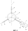
Фиг.2 - другой схематичный вид устройства с фиг.1;Figure 2 is another schematic view of the device of figure 1;
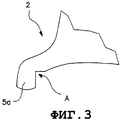
Фиг.3 - частичный вид в перспективе устройства с предыдущих чертежей;Figure 3 is a partial perspective view of the device from the previous drawings;
Фиг.4 - вид, соответствующий виду с фиг.1, второго варианта осуществления настоящего изобретения;FIG. 4 is a view corresponding to that of FIG. 1 of a second embodiment of the present invention;
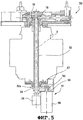
Фиг.5 - частичное осевое сечение варианта устройства с фиг.4; иFigure 5 is a partial axial section of a variant of the device of figure 4; and
Фиг.6 - вид в перспективе устройства с фиг.4 и 5.6 is a perspective view of the device of figures 4 and 5.
На фиг.1-3 ссылочной позицией 1 в целом обозначен первый вариант устройства согласно настоящему изобретению для центрирования и зажима полуобработанных (или менее чем полуобработанных) деталей, которые предназначены для последующей механической обработки. Устройство описано с конкретной ссылкой на колеса 2 транспортных средств, выполненные из легкого сплава, в частности, алюминиевого сплава; однако следует понимать, что такой вариант применения является предпочтительным, но не ограничивающим, поскольку изобретение с равной эффективностью может применяться в любом случае, если требуется центрировать и зажимать детали, имеющие осесимметричную геометрию (например, тормозные диски, маховики, барабаны и т.п.).1-3,
В данном контексте термин "колесо" предназначен для обозначения всей конструкции обода и колеса для транспортных средств, обычно снабженной перфорированным передним участком 3 (содержащим сквозные отверстия для крепления колеса к ступице автомобиля), от которого отходит стенка 4, проходящая почти цилиндрически и содержащая противоположные периферийные кромки 5а, 5b, выступающие по радиусу для образования контактной поверхности колеса с шиной.In this context, the term "wheel" is intended to mean the entire structure of the rim and wheel for vehicles, usually equipped with a perforated front section 3 (containing through holes for mounting the wheel to the hub of the car), from which the wall 4 extends almost cylindrically and contains opposite
Устройство 1 содержит опорную раму 6, на которой установлен стол 7, содержащий центральное сквозное отверстие 8.The
На столе 7 имеются три направляющих элемента 9, проходящих по радиусу относительно геометрической центральной оси устройства, обозначенной позицией Х, и отстоящие друг от друга на одинаковых расстояниях (120°).On the table 7 there are three guiding elements 9, passing along the radius relative to the geometric central axis of the device, indicated by the position X, and spaced from each other at equal distances (120 °).
Как вариант, возможны и другие конфигурации с другим количеством направляющих элементов и соответствующим угловым расстоянием.Alternatively, other configurations are possible with a different number of guide elements and corresponding angular distance.
Каждая направляющая 9 связана с соответствующим ползуном 10 соответствующего центрирующего элемента 11 для направления последнего в соответствующем радиальном направлении (показанном позицией Y на фиг.2) для поступательного движения к оси Х и от нее.Each guide 9 is associated with a
Центрирующие элементы 11 имеют идентичную конструкцию, и далее более подробно будет описан только один из них.The
Ползун 10 содержит на одном конце выступ 12, имеющий такой размер, чтобы взаимодействовать с кромкой 5а колеса при радиальном движении ползуна и, тем самым, оттягивать колесо от оси Х. Выступ 12 для удобства может быть концом съемного блока 13, прикрепленного к ползуну 10, который также определяет вертикальное положение детали.The
Имеется средство привода для перемещения каждого ползуна 10, содержащее приводной элемент, который для удобства имеет форму ходового винта 15, и который проходит вдоль оси и параллельно радиальному направлению Y соответствующего центрирующего элемента 11 и установлен с возможностью вращения на столе 7. Винт 15 вдоль своего осевого участка снабжен резьбой, которая взаимодействует с ответной внутренней резьбой 16, выполненной в ползуне 10. Более конкретно, привод относится к типу шариково-винтовой пары и соответствующая ответная внутренняя резьба расположена в конструкции 17 ходовой гайки в ползуне 10. В результате, вращение ходового винта 15 преобразуется в поступательное движение ходовой гайки 17 и выполненного с ней за одно целое ползуна 10 с соответствующим перемещением центрирующего элемента 11 в соответствующем радиальном направлении Y от оси Х или к ней.There is a drive means for moving each
Устройство 1 также содержит средство трансмиссии, содержащее в каждом ходовом винте соответствующую шестерню 18, посаженную на шпонке на свободном конце ходового винта. Три шестерни 18 находятся в зацеплении с зубчатым колесом 19, так что вращение одного из ходовых винтов 15 синхронно передается на другие ходовые винты. Имеются также известные сами по себе устройства для компенсации или устранения люфтов в имеющихся кинематических соединениях.The
Каждая шестерня 18 для удобства образует с зубчатым колесом 19 зубчатую пару с ортогональными осями, имеющую форму конического зубчатого колеса и конической шестерни.Each
Узел электродвигателя обозначен ссылочной позицией 20 и показан на чертежах только схематически, при этом узел электродвигателя выполнен с возможностью собственного независимого движения для обеспечения зацепления и оперативно связан с одним из ходовых винтов 15 для приведения его во вращение вокруг оси. Благодаря зацеплению шестерен 18 с зубчатым колесом 19 вращение, передаваемое электродвигателем 20 на один из ходовых винтов 15, передается синхронно на другие ходовые винты, обеспечивая синхронное перемещение всех трех центрирующих элементов 11. Следует отметить, что электродвигатель, прикрепленный к станку, выполнен с возможностью перемещения между заданными рабочими положениями (по меньшей мере, второе положение показано пунктирными линиями на фиг.2).The electric motor assembly is indicated by the
На каждом ползуне 10 также имеется зажимное средство 21 для детали, подлежащей центрированию, которое содержит зажимной кулачок 22, установленный сочлененно на ползуне с возможностью смещения к рабочему положению, в котором он прижат к колесу 2 на кромке 5а, для обеспечения его зажима.Each
Каждый ползун 10 может быть зажат относительно собственной направляющей соответствующим зажимным средством 23, содержащим, например, имеющие соответствующие размеры и питание гидравлические или пневматические цилиндры.Each
Благодаря наличию зажимного средства каждый центрирующий элемент зажимается с возможностью освобождения относительно стола 7, когда достигнуто заданное положение центрирования (вдоль направления Y).Due to the presence of the clamping means, each centering element is clamped so that it can be released relative to the table 7 when the predetermined centering position (along the Y direction) is reached.
При работе полуготовое колесо 2 сначала опирается на стол 7. На этой фазе центрирующие элементы 11 отведены назад к оси Х на одинаковое радиальное расстояние от этой оси таким образом, чтобы выступы 12 размещались между осью Х и периферийной кромкой 5а колеса.In operation, the
На следующей фазе три центрирующих элемента 11 синхронно перемещаются в своих соответствующих радиальных направлениях Y от оси Х под воздействием электродвигателя 20, который прикреплен к станку и снабжен собственным механизмом зацепления. Положение определяется датчиком положения (например, кодером) и проверкой крутящего момента зажима. Электродвигатель предпочтительно является электродвигателем управляемого движения, так что его вращением и, следовательно, поступательным перемещением соответствующего ползуна 10 можно управлять с высокой точностью.In the next phase, the three
В частности, конец каждого центрирующего элемента (блок 13) воздействует на заранее обработанную поверхность колеса, обозначенную на чертежах позицией А, и содержащую, например, три участка, расположенных под углом 120° относительно друг друга, как показано на фиг.3.In particular, the end of each centering element (block 13) acts on the pre-machined surface of the wheel, indicated by A in the drawings, and containing, for example, three sections located at an angle of 120 ° relative to each other, as shown in FIG. 3.
Когда будет достигнуто центральное положение колеса относительно оси Х, движение центрирующих элементов 11 останавливается и приводятся в действие зажимные средства 21, смещая каждый кулачок 22 на колесо 2. Одновременно каждый ползун зажимается относительно своей направляющей на столе 7 путем включения зажимного средства 23.When the central position of the wheel with respect to the X axis is reached, the movement of the
Если полуготовое колесо зажато в отцентрированном положении, то электродвигатель 20 останавливается и начинается выполнение фаз механической обработки, запланированных для соответствующих циклов обработки.If the semi-finished wheel is clamped in the centered position, the
В первую очередь, следует отметить, что с помощью устройства согласно настоящему изобретению можно осуществить центрирование деталей в широком диапазоне размеров деталей и, следовательно, с большим диапазоном хода центрирующих элементов. Например, на фиг.1 показано другое полуготовое колесо 2', отличающееся от колеса 2, очевидно, меньшим размером, но которое может быть также легко зажато в центральном положении посредством устройства 1.First of all, it should be noted that using the device according to the present invention, it is possible to center parts in a wide range of sizes of parts and, therefore, with a large range of stroke of the centering elements. For example, figure 1 shows another semi-finished wheel 2 ', different from the
Следует также отметить, что устройство согласно настоящему изобретению имеет такие размеры, чтобы обеспечить легкий доступ к полуготовым деталям, в частности, к передней поверхности 3 колеса, через центральное отверстие 8 опорной рамы 6. Для этого зубчатое колесо 19 выполнено пустотелым в центре (см. фиг.1) для обеспечения доступа к детали и возможного удаления литников (оставшихся от предшествующей операции отливки).It should also be noted that the device according to the present invention is dimensioned to provide easy access to semi-finished parts, in particular to the
Такая простота доступа позволяет выполнять последующие фазы обработки детали быстрее и без изменения положения полуготовой детали.Such ease of access allows the subsequent processing phases of the part to be completed faster and without changing the position of the semi-finished part.
Одно конкретное преимущество заключается в том, что центрирующее устройство согласно настоящему изобретению позволяет повысить гибкость и универсальность операций по центрированию и зажиму деталей, в частности, обеспечивая скорость и точность центрирования деталей, имеющих разные размеры и габариты (например, полуготовые колеса разных диаметров). Это позволяет преимущественно встраивать такие устройства в обрабатывающие центры, на которые подаются для обработки детали разных типов (в частности, с разными размерами относительно друг друга) и по существу в произвольной последовательности. Эти признаки, востребованные рынком, позволяют в реальном времени реагировать на рыночный спрос.One particular advantage is that the centering device according to the present invention improves the flexibility and versatility of centering and clamping parts, in particular, ensuring the speed and accuracy of centering of parts having different sizes and dimensions (e.g. semi-finished wheels of different diameters). This allows you to mainly embed such devices in the machining centers, which are fed for processing parts of different types (in particular, with different sizes relative to each other) and essentially in an arbitrary sequence. These features, demanded by the market, allow real-time response to market demand.
Другое преимущество состоит в том, что улучшился доступ к полуготовой детали, обеспечиваемый устройством согласно настоящему изобретению, которое, кроме того, имеет меньшие размеры по сравнению с известными решениями.Another advantage is that the access to the semi-finished part provided by the device according to the present invention is improved, which, in addition, is smaller in comparison with the known solutions.
Другое в равной степени существенное преимущество заключатся в том, что имеется возможность получения истинного центрирования детали, используя ее предварительно обрабатываемую поверхность А. Предусмотрено, что эти поверхности обрабатываются одновременно с обработкой крепежных отверстий колеса, что обеспечивает идеальную геометрию и, следовательно, более низкий уровень дисбаланса детали.Another equally significant advantage is that it is possible to obtain true centering of the part using its pre-machined surface A. It is envisaged that these surfaces are machined simultaneously with the machining of the mounting holes of the wheel, which provides ideal geometry and, therefore, a lower level of imbalance the details.
На фиг.4-6 ссылочной позицией 50 обозначен в целом второй вариант устройства для центрирования и зажима деталей, подлежащих механической обработке, выполненного согласно настоящему изобретению, причем детали, аналогичные деталям предыдущего варианта, обозначены теми же самыми ссылочными позициями.4-6,
Устройство 50 отличается от предыдущего варианта главным образом тем, что имеет привод, обозначенный ссылочной позицией 51, который не связан непосредственно с каким-либо центрирующим элементом, а соединен с осевым концом 52а трансмиссионного вала 52, на противоположном конце 52b которого установлено на шпонке зубчатое колесо 19.The
Вал 52 проходит, соосно с главной осью Х, от противоположной относительно рабочей зоны для центрирования и зажима деталей стороны стола 7 и имеет пустотелую трубчатую конструкцию. В результате, привод 51 расположен под столом 7.The
Ссылочной позицией 53 обозначен первый трансмиссионный шкив, выполненный за одно целое с валом 52 для вращения. Соответствующий второй шкив 54 установлен на шпонке на выходном валу 55 двигателя 56, входящего в узел 51 привода, предназначенного для приведения в действие центрирующих элементов 11. На шкивы 53 и 54 надет непрерывный кольцевой трансмиссионный ремень 57. Очевидно, что между двигателем 56 и валом 52 можно использовать другое средство кинематической трансмиссии, эквивалентное ременной передаче.
Ссылочной позицией 58 обозначен гидрораспределитель зажима, показанный лишь схематически и установленный на конце 52 вала, и с осевой полостью вала соединены линии гидрораспределителя, по которым масло подается вверх в зону стола 7 для выполнения функции зажима.
При работе, после вращения двигателя 56 и, следовательно, вала 52 и выполненного с ним за одно целое зубчатого колеса 19, синхронное вращение передается на ходовые винты 15, и благодаря зацеплению между зубчатым колесом 19 и шестернями 18 осуществляется синхронное поступательное перемещение трех центрирующих элементов 11, которые работают точно так же, как и в предыдущем варианте осуществления изобретения.During operation, after the rotation of the
В связи со вторым иллюстративным вариантом настоящего изобретения, помимо преимуществ уже указанных для предшествующего варианта, следует подчеркнуть, что такое размещение приводного устройства позволяет уменьшить поперечные габариты устройства, в частности, во внешних радиальных зонах, соответствующих центрирующим элементам.In connection with the second illustrative embodiment of the present invention, in addition to the advantages already indicated for the previous embodiment, it should be emphasized that this arrangement of the drive device allows to reduce the transverse dimensions of the device, in particular in the outer radial zones corresponding to the centering elements.
Другое преимущество заключается в том, что уменьшена вращающаяся масса рабочего стола (поскольку двигатель размещен под столом и не вращается с ним), с соответствующим уменьшением инерционных эффектов, возникающих при вращении стола.Another advantage is that the rotating mass of the working table is reduced (since the engine is placed under the table and does not rotate with it), with a corresponding decrease in the inertial effects that occur when the table is rotated.
Claims (17)
Applications Claiming Priority (2)
| Application Number | Priority Date | Filing Date | Title |
|---|---|---|---|
| ITPD2004A000177 | 2004-07-02 | ||
| IT000177A ITPD20040177A1 (en) | 2004-07-02 | 2004-07-02 | DEVICE FOR THE LOCKING IN THE CENTRAL POSITION OF PIECES TO BE SUBJECTED TO MECHANICAL AND MECHANICAL PROCESSING OF THE TOOL INCLUDING THIS DEVICE |
Publications (2)
| Publication Number | Publication Date |
|---|---|
| RU2007104030A RU2007104030A (en) | 2008-08-10 |
| RU2341382C2 true RU2341382C2 (en) | 2008-12-20 |
Family
ID=34959675
Family Applications (1)
| Application Number | Title | Priority Date | Filing Date |
|---|---|---|---|
| RU2007104030/11A RU2341382C2 (en) | 2004-07-02 | 2004-12-06 | Gripping socket and machine tool with this appliance |
Country Status (10)
| Country | Link |
|---|---|
| US (1) | US20070221337A1 (en) |
| EP (1) | EP1771308B1 (en) |
| KR (1) | KR20070028474A (en) |
| CN (1) | CN1997526A (en) |
| AT (1) | ATE411912T1 (en) |
| DE (1) | DE602004017371D1 (en) |
| IT (1) | ITPD20040177A1 (en) |
| MX (1) | MXPA06014829A (en) |
| RU (1) | RU2341382C2 (en) |
| WO (1) | WO2006003683A1 (en) |
Cited By (1)
| Publication number | Priority date | Publication date | Assignee | Title |
|---|---|---|---|---|
| RU2688027C1 (en) * | 2018-02-07 | 2019-05-17 | Вячеслав Сергеевич Перфильев | Drill, screwdriver or bench cartridge with target illumination |
Families Citing this family (25)
| Publication number | Priority date | Publication date | Assignee | Title |
|---|---|---|---|---|
| DE102006015432A1 (en) * | 2006-03-31 | 2007-10-04 | Rolls-Royce Deutschland Ltd & Co Kg | Workpiece holding system for a machine tool |
| ATE430640T1 (en) | 2006-11-03 | 2009-05-15 | Michel Yerly | HOLDING DEVICE FOR WORKPIECE |
| DE102008014835A1 (en) | 2008-03-07 | 2009-09-10 | Chiron-Werke Gmbh & Co Kg | Machine tool, in particular for wheel machining |
| DE102009033824B3 (en) * | 2009-07-18 | 2010-11-25 | Sterman Technische Systeme Gmbh | Device for clamping a workpiece |
| ES2498265T3 (en) * | 2010-03-02 | 2014-09-24 | Grob-Werke Gmbh & Co. Kg | Machining machine |
| DE102010044781A1 (en) * | 2010-03-02 | 2011-09-08 | Grob-Werke Gmbh & Co. Kg | Processing machine with drive shaft |
| DE102010044783A1 (en) * | 2010-03-02 | 2011-09-08 | Grob-Werke Gmbh & Co. Kg | processing machine |
| FR2971957B1 (en) * | 2011-02-28 | 2014-06-13 | Snecma | DAMPING VIBRATIONS GENERATED DURING TURBOMACHINE COMPRESSOR DRUMS TURNING |
| DE102011001866A1 (en) * | 2011-04-07 | 2012-10-11 | Mag Ias Gmbh | Workpiece clamping device and machine tool |
| CN102423859B (en) * | 2011-09-15 | 2012-11-21 | 常熟市建华模具有限责任公司 | Clamp device for processing glass mould |
| CN102744573A (en) * | 2012-07-12 | 2012-10-24 | 中信戴卡股份有限公司 | Aluminum alloy wheel manufacturing method |
| CN102848246B (en) * | 2012-08-07 | 2014-06-11 | 常熟建华模具科技股份有限公司 | Work fixture for glass mould machining |
| IT1422638B1 (en) * | 2014-03-04 | 2016-06-03 | Imt Intermato S P A | Equipment and method for locking a metal alloy wheel in a machine for mechanical processing |
| CN104842164A (en) * | 2015-05-04 | 2015-08-19 | 天津戴卡轮毂制造有限公司 | Vehicle wheel machining method based on harmonic wave low point and eccentric mandrel |
| CN104972416A (en) * | 2015-06-12 | 2015-10-14 | 中信戴卡股份有限公司 | Circumferential positioning device for wheel |
| CN105522425A (en) * | 2016-01-21 | 2016-04-27 | 中信戴卡股份有限公司 | Lathe chuck plate of aluminum alloy hub |
| CN105798680A (en) * | 2016-05-01 | 2016-07-27 | 中信戴卡股份有限公司 | Automobile wheel lathe clamp |
| CN106624927A (en) * | 2017-01-18 | 2017-05-10 | 中信戴卡股份有限公司 | Wheel fixture |
| CN107225263A (en) * | 2017-06-13 | 2017-10-03 | 中信戴卡股份有限公司 | Multi-functional adjustable rig |
| CN108673373A (en) * | 2018-05-24 | 2018-10-19 | 中信戴卡股份有限公司 | A kind of fixture of hub surface patch balance weight |
| FR3081549B1 (en) * | 2018-05-25 | 2021-08-06 | Safran Aircraft Engines Mexico | DEVICE FOR POSITIONING AND HOLDING A TURBOMACHINE ANNULAR ELEMENT |
| CN109834474B (en) * | 2019-03-29 | 2023-09-15 | 中信戴卡股份有限公司 | Hub tooling positioning fixture |
| CN110524279B (en) * | 2019-09-11 | 2021-03-19 | 四川航天长征装备制造有限公司 | Ji tablet back chipping device |
| US11655891B2 (en) * | 2020-09-09 | 2023-05-23 | Mahindra N.A. Tech Center | Method of machining an axle carrier housing |
| CN114193351B (en) * | 2021-11-19 | 2023-10-13 | 徐州铭德轴承有限公司 | Supporting device for bearing machining |
Family Cites Families (19)
| Publication number | Priority date | Publication date | Assignee | Title |
|---|---|---|---|---|
| US1251138A (en) * | 1916-09-23 | 1917-12-25 | Goodyear Tire & Rubber | Tire-mounting chuck. |
| US1535183A (en) * | 1919-11-18 | 1925-04-28 | Frank C Smart | Lathe chuck |
| US1460385A (en) * | 1920-07-08 | 1923-07-03 | Niles Bement Pond Co | Tire clamp |
| US1633828A (en) * | 1922-05-05 | 1927-06-28 | Cushman Chuck Co | Chuck |
| US1971638A (en) * | 1931-09-04 | 1934-08-28 | Berg Wilhelm | Motor operated chuck for lathes and other machine tools |
| US2196402A (en) * | 1937-08-13 | 1940-04-09 | Westinghouse Electric & Mfg Co | Motor control system |
| US2225273A (en) * | 1939-01-13 | 1940-12-17 | Phillips Petroleum Co | Rotating adjustable tilting table chuck |
| US2245384A (en) * | 1939-02-16 | 1941-06-10 | Bullard Co | Chuck operating mechanism |
| US3233910A (en) * | 1963-05-14 | 1966-02-08 | Lloyd A Pfaff | Welding work centering chuck |
| CH444694A (en) * | 1965-11-26 | 1967-09-30 | Duquesne Victor | Device for mounting and removing tires from motor vehicle wheels |
| BE672886A (en) * | 1965-11-26 | 1966-03-16 | ||
| GB1384879A (en) * | 1971-05-12 | 1975-02-26 | Dunlop Ltd | Apparatus for use in mounting tyres on and removing tyres from wheel rims |
| US4165662A (en) * | 1977-12-23 | 1979-08-28 | Besenbruch-Hofmann Of Puerto Rico, Inc. | Work holder assembly for lathe used in dressing cylindrical and disc shaped articles |
| US4482163A (en) * | 1982-09-29 | 1984-11-13 | Litton Industrial Products, Inc. | Spindle powered adjustable chuck |
| DE3580870D1 (en) * | 1984-06-29 | 1991-01-24 | Quesne Francois Du | MECHANISM FOR ATTACHING A WHEEL RIM TO A TIRE ASSEMBLY AND REMOVAL DEVICE. |
| JP2002214374A (en) * | 2001-01-15 | 2002-07-31 | Agilent Technologies Japan Ltd | Positioning device and positioning method |
| DE10256870A1 (en) * | 2002-12-04 | 2004-06-24 | Schenck Rotec Gmbh | Tensioning device for rims, in particular for mounting tires |
| ITVR20030062A1 (en) * | 2003-05-19 | 2004-11-20 | Butler Eng & Marketing | MAINTENANCE EQUIPMENT OF A WHEELED WHEEL |
| ITMO20040006U1 (en) * | 2004-03-11 | 2004-06-11 | Sicam Srl | SPINDLE FOR ATTACHING WHEEL RIMS FOR VEHICLES ON WORKSHOP MACHINES |
-
2004
- 2004-07-02 IT IT000177A patent/ITPD20040177A1/en unknown
- 2004-12-06 KR KR1020067027814A patent/KR20070028474A/en not_active Application Discontinuation
- 2004-12-06 WO PCT/IT2004/000678 patent/WO2006003683A1/en active Application Filing
- 2004-12-06 RU RU2007104030/11A patent/RU2341382C2/en not_active IP Right Cessation
- 2004-12-06 DE DE602004017371T patent/DE602004017371D1/en not_active Expired - Fee Related
- 2004-12-06 MX MXPA06014829A patent/MXPA06014829A/en not_active Application Discontinuation
- 2004-12-06 EP EP04806843A patent/EP1771308B1/en active Active
- 2004-12-06 CN CNA2004800434931A patent/CN1997526A/en active Pending
- 2004-12-06 US US11/630,636 patent/US20070221337A1/en not_active Abandoned
- 2004-12-06 AT AT04806843T patent/ATE411912T1/en not_active IP Right Cessation
Cited By (1)
| Publication number | Priority date | Publication date | Assignee | Title |
|---|---|---|---|---|
| RU2688027C1 (en) * | 2018-02-07 | 2019-05-17 | Вячеслав Сергеевич Перфильев | Drill, screwdriver or bench cartridge with target illumination |
Also Published As
| Publication number | Publication date |
|---|---|
| EP1771308A1 (en) | 2007-04-11 |
| RU2007104030A (en) | 2008-08-10 |
| ITPD20040177A1 (en) | 2004-10-02 |
| CN1997526A (en) | 2007-07-11 |
| WO2006003683A1 (en) | 2006-01-12 |
| KR20070028474A (en) | 2007-03-12 |
| ATE411912T1 (en) | 2008-11-15 |
| MXPA06014829A (en) | 2007-03-07 |
| EP1771308B1 (en) | 2008-10-22 |
| DE602004017371D1 (en) | 2008-12-04 |
| US20070221337A1 (en) | 2007-09-27 |
Similar Documents
| Publication | Publication Date | Title |
|---|---|---|
| RU2341382C2 (en) | Gripping socket and machine tool with this appliance | |
| CN102765002B (en) | Automatic centering fixture for workpiece with revolution boss and/or hole | |
| EP1776206A1 (en) | A device for centering and magnetic clamping of workpieces and a machine tool incorporating the said device | |
| WO2022051894A1 (en) | Horizontal numerical control crankshaft machining apparatus | |
| JPS5818161B2 (en) | Tokuni Tajiku Kaitenji Douban Tokuni Tajiku Kaitenji Douban | |
| US3740806A (en) | Automatic tool machine having a multi position indexing arrangement | |
| JPS58171229A (en) | Structure of table for machining center | |
| US5544556A (en) | Reversibly rotatable chuck with internal cam for shifting work axis | |
| US4482163A (en) | Spindle powered adjustable chuck | |
| JP4256098B2 (en) | 2-spindle facing lathe | |
| CN210475589U (en) | Auxiliary device based on lathe processing | |
| US4528876A (en) | Universal single spindle pin crankshaft lathe | |
| RU2003127894A (en) | UNIVERSAL TABLE MACHINE | |
| CN113814839A (en) | Shell machining device | |
| CN220073954U (en) | Automobile brake pad perforating device | |
| JP2001038503A (en) | Machining head device | |
| RU2200075C2 (en) | Mobile apparatus for turning ends of large-size shells | |
| JP2670508B2 (en) | Grinding wheel cutting device and honing machine | |
| CN115007895B (en) | Vision centering device | |
| CN219725918U (en) | Rotatable clamp for processing elevator spare and accessory parts | |
| CN220145242U (en) | Positioning tool for machining mechanical parts | |
| CN110369749B (en) | Auxiliary device based on lathe processing | |
| JPH09155667A (en) | Rotary multishaft spindle head device | |
| JP2003181705A (en) | Rotary tool turret and opposed double main spindle lathe | |
| JP2837034B2 (en) | Grinding equipment |
Legal Events
| Date | Code | Title | Description |
|---|---|---|---|
| MM4A | The patent is invalid due to non-payment of fees |
Effective date: 20091207 |