RU2294441C2 - Fluid medium swirling device for internal combustion engine (versions) - Google Patents
Fluid medium swirling device for internal combustion engine (versions) Download PDFInfo
- Publication number
- RU2294441C2 RU2294441C2 RU2004135548/06A RU2004135548A RU2294441C2 RU 2294441 C2 RU2294441 C2 RU 2294441C2 RU 2004135548/06 A RU2004135548/06 A RU 2004135548/06A RU 2004135548 A RU2004135548 A RU 2004135548A RU 2294441 C2 RU2294441 C2 RU 2294441C2
- Authority
- RU
- Russia
- Prior art keywords
- specified
- housing
- blades
- primary blades
- primary
- Prior art date
Links
- 238000002485 combustion reaction Methods 0.000 title claims abstract description 37
- 239000012530 fluid Substances 0.000 title claims description 117
- 239000007789 gas Substances 0.000 claims abstract description 23
- 238000005452 bending Methods 0.000 claims description 12
- 238000009434 installation Methods 0.000 claims description 10
- 239000007788 liquid Substances 0.000 claims description 2
- 239000000446 fuel Substances 0.000 abstract description 15
- 230000000694 effects Effects 0.000 abstract description 2
- 239000000203 mixture Substances 0.000 abstract description 2
- 238000011089 mechanical engineering Methods 0.000 abstract 1
- 239000000126 substance Substances 0.000 abstract 1
- 230000002093 peripheral effect Effects 0.000 description 11
- 230000004048 modification Effects 0.000 description 3
- 238000012986 modification Methods 0.000 description 3
- 239000002245 particle Substances 0.000 description 3
- 239000003054 catalyst Substances 0.000 description 2
- 230000003197 catalytic effect Effects 0.000 description 2
- 239000013013 elastic material Substances 0.000 description 2
- 238000002347 injection Methods 0.000 description 2
- 239000007924 injection Substances 0.000 description 2
- 229910001220 stainless steel Inorganic materials 0.000 description 2
- 239000010935 stainless steel Substances 0.000 description 2
- 230000000712 assembly Effects 0.000 description 1
- 238000000429 assembly Methods 0.000 description 1
- 238000000889 atomisation Methods 0.000 description 1
- 230000015572 biosynthetic process Effects 0.000 description 1
- 230000003247 decreasing effect Effects 0.000 description 1
- 238000006073 displacement reaction Methods 0.000 description 1
- 239000007787 solid Substances 0.000 description 1
- 239000000243 solution Substances 0.000 description 1
Images


Classifications
-
- F—MECHANICAL ENGINEERING; LIGHTING; HEATING; WEAPONS; BLASTING
- F02—COMBUSTION ENGINES; HOT-GAS OR COMBUSTION-PRODUCT ENGINE PLANTS
- F02B—INTERNAL-COMBUSTION PISTON ENGINES; COMBUSTION ENGINES IN GENERAL
- F02B27/00—Use of kinetic or wave energy of charge in induction systems, or of combustion residues in exhaust systems, for improving quantity of charge or for increasing removal of combustion residues
- F02B27/04—Use of kinetic or wave energy of charge in induction systems, or of combustion residues in exhaust systems, for improving quantity of charge or for increasing removal of combustion residues in exhaust systems only, e.g. for sucking-off combustion gases
-
- F—MECHANICAL ENGINEERING; LIGHTING; HEATING; WEAPONS; BLASTING
- F02—COMBUSTION ENGINES; HOT-GAS OR COMBUSTION-PRODUCT ENGINE PLANTS
- F02B—INTERNAL-COMBUSTION PISTON ENGINES; COMBUSTION ENGINES IN GENERAL
- F02B31/00—Modifying induction systems for imparting a rotation to the charge in the cylinder
-
- B—PERFORMING OPERATIONS; TRANSPORTING
- B01—PHYSICAL OR CHEMICAL PROCESSES OR APPARATUS IN GENERAL
- B01F—MIXING, e.g. DISSOLVING, EMULSIFYING OR DISPERSING
- B01F25/00—Flow mixers; Mixers for falling materials, e.g. solid particles
- B01F25/40—Static mixers
- B01F25/42—Static mixers in which the mixing is affected by moving the components jointly in changing directions, e.g. in tubes provided with baffles or obstructions
- B01F25/43—Mixing tubes, e.g. wherein the material is moved in a radial or partly reversed direction
- B01F25/431—Straight mixing tubes with baffles or obstructions that do not cause substantial pressure drop; Baffles therefor
- B01F25/4316—Straight mixing tubes with baffles or obstructions that do not cause substantial pressure drop; Baffles therefor the baffles being flat pieces of material, e.g. intermeshing, fixed to the wall or fixed on a central rod
-
- F—MECHANICAL ENGINEERING; LIGHTING; HEATING; WEAPONS; BLASTING
- F02—COMBUSTION ENGINES; HOT-GAS OR COMBUSTION-PRODUCT ENGINE PLANTS
- F02B—INTERNAL-COMBUSTION PISTON ENGINES; COMBUSTION ENGINES IN GENERAL
- F02B31/00—Modifying induction systems for imparting a rotation to the charge in the cylinder
- F02B31/04—Modifying induction systems for imparting a rotation to the charge in the cylinder by means within the induction channel, e.g. deflectors
-
- F—MECHANICAL ENGINEERING; LIGHTING; HEATING; WEAPONS; BLASTING
- F02—COMBUSTION ENGINES; HOT-GAS OR COMBUSTION-PRODUCT ENGINE PLANTS
- F02M—SUPPLYING COMBUSTION ENGINES IN GENERAL WITH COMBUSTIBLE MIXTURES OR CONSTITUENTS THEREOF
- F02M29/00—Apparatus for re-atomising condensed fuel or homogenising fuel-air mixture
- F02M29/04—Apparatus for re-atomising condensed fuel or homogenising fuel-air mixture having screens, gratings, baffles or the like
- F02M29/06—Apparatus for re-atomising condensed fuel or homogenising fuel-air mixture having screens, gratings, baffles or the like generating whirling motion of mixture
-
- B—PERFORMING OPERATIONS; TRANSPORTING
- B01—PHYSICAL OR CHEMICAL PROCESSES OR APPARATUS IN GENERAL
- B01F—MIXING, e.g. DISSOLVING, EMULSIFYING OR DISPERSING
- B01F25/00—Flow mixers; Mixers for falling materials, e.g. solid particles
- B01F25/40—Static mixers
- B01F25/42—Static mixers in which the mixing is affected by moving the components jointly in changing directions, e.g. in tubes provided with baffles or obstructions
- B01F25/43—Mixing tubes, e.g. wherein the material is moved in a radial or partly reversed direction
- B01F25/431—Straight mixing tubes with baffles or obstructions that do not cause substantial pressure drop; Baffles therefor
- B01F25/43197—Straight mixing tubes with baffles or obstructions that do not cause substantial pressure drop; Baffles therefor characterised by the mounting of the baffles or obstructions
- B01F25/431974—Support members, e.g. tubular collars, with projecting baffles fitted inside the mixing tube or adjacent to the inner wall
-
- Y—GENERAL TAGGING OF NEW TECHNOLOGICAL DEVELOPMENTS; GENERAL TAGGING OF CROSS-SECTIONAL TECHNOLOGIES SPANNING OVER SEVERAL SECTIONS OF THE IPC; TECHNICAL SUBJECTS COVERED BY FORMER USPC CROSS-REFERENCE ART COLLECTIONS [XRACs] AND DIGESTS
- Y02—TECHNOLOGIES OR APPLICATIONS FOR MITIGATION OR ADAPTATION AGAINST CLIMATE CHANGE
- Y02T—CLIMATE CHANGE MITIGATION TECHNOLOGIES RELATED TO TRANSPORTATION
- Y02T10/00—Road transport of goods or passengers
- Y02T10/10—Internal combustion engine [ICE] based vehicles
- Y02T10/12—Improving ICE efficiencies
Abstract
Description
Изобретение в основном имеет отношение к системам впуска и выпуска двигателей внутреннего сгорания. Более конкретно, изобретение имеет отношение к таким системам впуска, которые обеспечивают повышенную эффективность сгорания путем более полного смешивания воздуха и топлива в текучей среде, проходящей через канал впуска. Изобретение также имеет отношение к таким системам выпуска отработавших газов, которые обеспечивают повышенную эффективность сгорания путем изменения потока отработавших газов, проходящих через систему выпуска отработавших газов.The invention mainly relates to intake and exhaust systems of internal combustion engines. More specifically, the invention relates to such intake systems that provide increased combustion efficiency by more fully mixing air and fuel in a fluid passing through the intake channel. The invention also relates to such exhaust gas systems that provide increased combustion efficiency by altering the exhaust gas flow through the exhaust gas system.
В системе впуска обычного двигателя внутреннего сгорания поток текучей среды, который перемещается по стенкам канала впуска, то есть ламинарный поток текучей среды, обычно включает значительное количество частиц бензина, которые не распылены. Топливо, которое не распылено, не готово к воспламенению. Таким образом, неполное распыление топлива в потоке текучей среды препятствует полному сгоранию текучей среды. Следовательно, такой ламинарный поток в двигателе снижает эффективность сгорания. Кроме того, из-за сил трения, возникающих вследствие контакта потока текучей среды со стенками канала впуска и разности в плотности массы между молекулами бензина и молекулами воздуха, ламинарный поток текучей среды перемещается по каналу с более медленной скоростью, чем остальная часть потока текучей среды. Кроме того, эта разность в скорости имеет тенденцию препятствовать смешиванию частиц бензина с частицами воздуха и, таким образом, способствует неполному сгоранию текучей среды и снижению эффективности (КПД) двигателя.In the intake system of a conventional internal combustion engine, a fluid stream that moves along the walls of the intake channel, i.e. a laminar fluid stream, typically includes a significant amount of gasoline particles that are not atomized. Fuel that is not atomized is not ready for ignition. Thus, incomplete atomization of the fuel in the fluid stream prevents the complete combustion of the fluid. Therefore, such a laminar flow in the engine reduces combustion efficiency. In addition, due to the frictional forces resulting from the contact of the fluid flow with the walls of the inlet channel and the difference in mass density between gasoline molecules and air molecules, the laminar fluid flow moves through the channel at a slower speed than the rest of the fluid flow. In addition, this difference in speed tends to prevent the mixing of gasoline particles with air particles and, thus, contributes to incomplete combustion of the fluid and lower engine efficiency.
Турбулентность потока текучей среды, проходящего по каналу впуска, ослабляет ламинарный поток текучей среды и обеспечивает лучшее смешивание воздуха с топливом. Такие преимущества могут быть реализованы в том случае, если турбулентность создается либо в воздухе, поступающем в карбюратор (или инжекторно-топливную систему), либо в текучей среде, проходящей через впускной коллектор, или в текучей среде, проходящей по каналам впуска или вокруг впускных клапанов двигателя. Таким образом, были разработаны различные устройства и системы с целью создания такой турбулентности в различных местах системы впуска.The turbulence of the fluid flow passing through the inlet channel weakens the laminar fluid flow and provides better mixing of air with the fuel. Such advantages can be realized if turbulence is created either in the air entering the carburetor (or fuel injector system), or in the fluid passing through the intake manifold, or in the fluid passing through the intake ducts or around the intake valves engine. Thus, various devices and systems have been developed to create such turbulence in various places of the intake system.
Некоторые известные устройства, которые были разработаны для создания турбулентности в воздухе, поступающем в подсистему подачи топлива, включают в себя лопасти, отклоняющие проходящий воздух в противоположное направление для образования в воздухе завихряющего движения. Некоторые такие устройства включают в себя втулку или центральный элемент, на котором смонтированы лопасти устройства. Центральный элемент обеспечивает жесткость лопастям так, чтобы они не абсорбировали энергию отклонения, а передавали эту энергию обратно текучей среде. Центральному элементу обычно придают обтекаемую форму для того, чтобы снизить стеснение потока текучей среды и уменьшить области отрицательного давления, которые могут создать нежелательную турбулентность.Some known devices that were designed to create turbulence in the air entering the fuel supply subsystem include blades deflecting the passing air in the opposite direction to cause swirling motion in the air. Some such devices include a sleeve or a central element on which the blades of the device are mounted. The central element provides rigidity to the blades so that they do not absorb deflection energy, but transfer this energy back to the fluid. The central element is usually streamlined in order to reduce the restriction of the fluid flow and to reduce areas of negative pressure that can create undesirable turbulence.
Одним из основных недостатков известных устройств или систем, которые генерируют турбулентность всасываемого воздуха, является то, что они ограничивают воздушный поток через систему. Это нежелательно сокращает максимальный объем поступающих в двигатель воздуха и топлива и, таким образом, снижает максимальную эффективную мощность (КПД) двигателя. Пример известного устройства, которое генерирует завихрение, а также турбулентность всасываемого воздуха, указан в Патенте США №5947081, Ким (Kim). Указанное устройство включает в себя лопасти с вогнутыми и выпуклыми участками и щелями. Маленькие вогнутые и выпуклые участки поверхности лопастей отклоняют небольшие части воздушного потока на относительно острые углы. Этот высокий уровень отклонения генерирует турбулентность воздушного потока. Эта турбулентность включает в себя скорее столкновение молекул потока текучей среды, чем плавное смешивание или перемешивание потока текучей среды. Следовательно, столкновения абсорбируют энергию и, таким образом, снижают скорость потока текучей среды и, следовательно, сокращают поток текучей среды.One of the main disadvantages of the known devices or systems that generate turbulence of intake air is that they restrict the air flow through the system. This undesirably reduces the maximum amount of air and fuel entering the engine and, thus, reduces the maximum effective power (efficiency) of the engine. An example of a known device that generates turbulence, as well as turbulence of the intake air, is indicated in US Patent No. 5947081, Kim. The specified device includes blades with concave and convex sections and crevices. Small concave and convex portions of the surface of the blades deflect small parts of the air flow at relatively sharp angles. This high level of deflection generates air flow turbulence. This turbulence involves colliding molecules of a fluid stream rather than smoothly mixing or mixing the fluid stream. Therefore, collisions absorb energy and, thus, reduce the flow rate of the fluid and, therefore, reduce the flow of fluid.
Другим важным недостатком некоторых известных устройств является то, что они сложны или дороги для установки в систему двигателя.Another important drawback of some known devices is that they are complex or expensive to install in an engine system.
Некоторые известные устройства, как, например, устройство, указанное в Патенте США №4424777, Кломп (Klomp), требуют их установки вокруг впускных клапанов, а это вынуждает покупателя разбирать двигатель и производить соответствующую машинную обработку компонентов двигателя для адаптации этих компонентов с устройством. Но это обычно длительное и дорогостоящее мероприятие, делающее такие устройства неприемлемыми для многих владельцев автомашин. Точно так же другие известные устройства требуют их установки во впускной коллектор или каналы, что вынуждает покупателя демонтировать крупные узлы двигателя для установки таких устройств. Но это длительное мероприятие, требующее от механика высокой квалификации и делающее такие устройства неприемлемыми для многих владельцев автомашин.Some well-known devices, such as, for example, the device indicated in US Pat. No. 4,424,777 to Klomp, require their installation around the inlet valves, and this forces the customer to disassemble the engine and properly machine the engine components to adapt these components to the device. But this is usually a lengthy and costly undertaking making such devices unacceptable to many car owners. Similarly, other known devices require their installation in the intake manifold or channels, which forces the buyer to dismantle large engine assemblies to install such devices. But this is a lengthy event, requiring a highly qualified mechanic and making such devices unacceptable to many car owners.
Проектировщики таких известных систем генерации турбулентности текучей среды впуска признали, что эффективность такой турбулентности изменяется в зависимости от положения дроссельной заслонки двигателя. Патент США №4424598, Тсатсуми (Tsutsumi), описывающий автомобильную систему генерации завихрения, которая реагирует на нагрузку двигателя и эксплуатационные условия двигателя.Designers of such well-known intake fluid turbulence generation systems have recognized that the efficiency of such turbulence varies with the position of the engine throttle. US patent No. 4424598, Tsutsumi (Tsutsumi), describing an automotive turbulence generation system that responds to engine load and engine operating conditions.
В основном, система Тсатсуми (Tsutsumi) использует вращающуюся ось, реагирующую на положение дроссельной заслонки карбюратора для изменения завихрения, генерируемого в камере сгорания. Однако недостатком указанной системы является сложность в ее точной установке.Basically, the Tsutsumi system uses a rotating axis that responds to the position of the carburetor throttle to change the turbulence generated in the combustion chamber. However, the disadvantage of this system is the difficulty in its accurate installation.
Проектировщики систем выпуска отработавших газов также признали, что повышение эффективности потока отработавших газов из двигателя может обеспечить повышение эффективности сгорания. Следовательно, существовало много систем выпуска отработавших газов, в которых стремились увеличивать скорость потока газов, выходящих из системы выпуска отработавших газов, и, таким образом, удалять отработавшие газы из камеры сгорания и выпускных каналов.Exhaust system designers have also recognized that increasing the efficiency of the exhaust gas stream from the engine can provide increased combustion efficiency. Therefore, there were many exhaust systems, in which they sought to increase the flow rate of gases leaving the exhaust system, and thus remove exhaust gases from the combustion chamber and exhaust channels.
Некоторые системы коллектора отработавших газов были разработаны для установки выхлопных труб по внутреннему периметру канала коллектора для завихрения отработавших газов в вихревой поток из канала коллектора и, таким образом, увеличения потока отработавших газов из коллектора. Такие системы были очень эффективны для совершенствования потока выпуска отработавших газов и потока текучей среды при впуске, что повысило эффективность сгорания. Однако такие системы требуют повторной регулировки двигателя и замены компонентов системы двигателя, что неприемлемо для многих владельцев автомашин.Some exhaust manifold systems have been developed to install exhaust pipes around the inner perimeter of the manifold channel to swirl the exhaust gases into the vortex stream from the manifold channel and thereby increase the exhaust stream from the manifold. Such systems were very effective in improving the exhaust flow and the inlet fluid flow, which increased combustion efficiency. However, such systems require re-adjusting the engine and replacing the components of the engine system, which is unacceptable to many car owners.
Многочисленные требования, предъявляемые к таким устройствам и системам генерации завихрения воздуха или воздушной турбулентности, нашли отражение в известных устройствах и системах, в которых находят место компромиссы между эффективностью генерирования завихрения или турбулентности и ограничением воздушного потока. Кроме того, существовало множество известных систем, которые были очень эффективны для генерации требуемого завихрения или турбулентности, но все они требовали чрезмерной модификации компонентов двигателя и трудовых затрат.Numerous requirements for such devices and systems for generating air turbulence or air turbulence are reflected in known devices and systems in which there are trade-offs between the efficiency of generating turbulence or turbulence and the restriction of air flow. In addition, there were many well-known systems that were very effective in generating the required turbulence or turbulence, but all of them required excessive modification of engine components and labor costs.
Следовательно, необходимым является устройство завихрения текучей среды при впуске и выпуске, которое не требует специальных инструментальных средств для его установки и, таким образом, может быть легко установлено вручную. Также необходимым является устройство завихрения текучей среды при впуске и выпуске, которое обеспечивает более эффективную генерацию завихрения с минимальным ограничением потока текучей среды.Therefore, a device for swirling the fluid at the inlet and outlet is necessary, which does not require special tools for its installation and, thus, can be easily installed manually. Also necessary is a device for swirling the fluid at the inlet and outlet, which provides a more efficient generation of swirl with minimal restriction of fluid flow.
Основной задачей настоящего изобретения является разработка устройства завихрения воздуха, которое может быть установлено в канал впуска воздуха, поступающего в топливную подсистему двигателя внутреннего сгорания.The main objective of the present invention is to develop a device for swirling air, which can be installed in the inlet channel of the air entering the fuel subsystem of the internal combustion engine.
Другой задачей настоящего изобретения является разработка устройства завихрения потока текучей среды при впуске и потока текучей среды при выпуске отработавших газов, включающее в себя конструктивные элементы, установленные под углом и имеющие профиль, обеспечивающий более эффективное завихрение потока текучей среды.Another objective of the present invention is to provide a device for swirling a fluid flow at the inlet and a fluid flow at the exhaust gas outlet, including structural elements installed at an angle and having a profile that provides a more efficient swirl of the fluid flow.
Следующей задачей настоящего изобретения является разработка устройства завихрения потока текучей среды при впуске и потока текучей среды при выпуске отработавших газов, включающее в себя минимальное число конструктивных элементов и обеспечивающее минимальное ограничение проходящего через него потока текучей среды.A further object of the present invention is to provide a device for swirling a fluid stream at an inlet and a fluid stream at an exhaust outlet, including a minimum number of structural elements and providing a minimum restriction of the fluid stream passing through it.
Очередной задачей настоящего изобретения является разработка устройства завихрения потока текучей среды при впуске и потока текучей среды на выпуске отработавших газов, включающее в себя конструктивные элементы, имеющие профиль, обеспечивающий минимальное ограничение проходящего через него потока текучей среды.Another objective of the present invention is to develop a device for swirling the fluid flow at the inlet and the fluid flow at the exhaust outlet, including structural elements having a profile that provides minimal restriction of the fluid flow passing through it.
Очередной задачей настоящего изобретения является разработка устройства завихрения потока воздуха, которое не требует разборки основных компонентов двигателя для установки этого устройства.Another objective of the present invention is to develop a device for swirling the air flow, which does not require disassembly of the main components of the engine to install this device.
Очередной задачей настоящего изобретения является разработка устройства завихрения потока воздуха, которое может быть вручную установлено в канал впуска воздуха двигателя внутреннего сгорания.A further object of the present invention is to provide an air flow swirl device that can be manually installed in the air intake channel of an internal combustion engine.
Очередной задачей настоящего изобретения является разработка устройства завихрения потока воздуха, обладающее структурной упругостью, обеспечивающей прочную посадку в канале впуска воздуха двигателя внутреннего сгорания.Another objective of the present invention is to develop a device for swirling the air flow, having structural elasticity, providing a solid fit in the air intake channel of an internal combustion engine.
Очередной задачей настоящего изобретения является разработка устройства завихрения потока отработавшего газа, которое снижает обратное давление.A further object of the present invention is to provide an exhaust gas swirl device that reduces back pressure.
По существу, устройство, описанное в настоящем изобретении, разработано для установки в канал потока текучей среды двигателя внутреннего сгорания и отклонения потока, проходящего через указанный канал, для того, чтобы придавать вращательное движение или завихрение текучей среде. Это движение завихрения приводит к смещению потока текучей среды от стенок канала и сокращает непрерывный контакт со стенками канала, что создает силы трения, увеличивающие торможение потока текучей среды. После установки устройства в канал впуска генерируемое завихрение обеспечивает более эффективное смешивание воздуха и топлива, что способствует более полному сгоранию воздушно-топливной смеси. После установки устройства в приемную или выхлопную трубу, генерируемое завихрение препятствует снижению скорости отработавших газов путем снижения обратного давления и, следовательно, увеличивает выходную мощность (КПД) двигателя.Essentially, the device described in the present invention is designed to be installed in a fluid channel of an internal combustion engine and to deflect a stream passing through said channel in order to impart a rotational motion or swirl to the fluid. This swirl motion displaces the fluid flow from the channel walls and reduces continuous contact with the channel walls, which creates frictional forces that increase the drag of the fluid flow. After installing the device in the intake channel, the generated turbulence provides a more efficient mixing of air and fuel, which contributes to a more complete combustion of the air-fuel mixture. After installing the device in the exhaust or exhaust pipe, the generated turbulence prevents the exhaust gas velocity from decreasing by reducing the back pressure and, therefore, increases the output power (efficiency) of the engine.
Устройство обеспечивает завихрение потока текучей среды путем использования лопастей, установленных в потоке текучей среды. Лопасти установлены под углом таким образом, чтобы преобразовывать движение текучей среды по стенкам канала во вращательное движение.The device provides swirling fluid flow by using blades mounted in the fluid flow. The blades are mounted at an angle so as to convert the movement of the fluid along the walls of the channel into rotational motion.
Устройство включает корпус, в котором установлены лопасти. Для прохода потока текучей среды корпус открыт с двух продольных концов. Корпус имеет размеры и форму, обеспечивающие его установку в трубопроводы или каналы впуска, а также выхлопные трубы различных автомашин. Это свойство позволяет пользователю относительно легко и просто вручную установить устройство в канал впуска или выхлопную трубу, куда оно плотно входит и остается на месте без необходимости в дополнительном креплении для его фиксации по месту установки.The device includes a housing in which the blades are installed. For passage of fluid flow, the housing is open from two longitudinal ends. The housing has dimensions and shape, ensuring its installation in pipelines or intake channels, as well as exhaust pipes of various vehicles. This property allows the user to relatively easily and simply manually install the device into the intake channel or exhaust pipe, where it fits tightly and remains in place without the need for additional fastening to fix it at the installation site.
Лопасти специально изогнуты (по краям) и имеют форму, обеспечивающую максимальную эффективность при генерации эффекта завихрения при минимальном ограничении потока текучей среды. По внутренней границе корпуса лопасти имеют длину большую, чем их длина в центральной части корпуса. Таким образом, удаленные от центра части лопастей большие и поэтому обеспечивают большее отклонение, чем меньшие части лопастей, расположенные у центра.The blades are specially curved (at the edges) and have a shape that provides maximum efficiency when generating a swirl effect with minimal restriction of the fluid flow. On the inner border of the casing, the blades are longer than their length in the central part of the casing. Thus, the parts of the blades remote from the center are large and therefore provide a greater deviation than the smaller parts of the blades located at the center.
Это решение желательно, поскольку обеспечивает более эффективную генерацию требуемого завихрения.This solution is desirable because it provides more efficient generation of the required turbulence.
Так как генерируемое завихрение по существу является вращением воздуха относительно центральной оси с большим количеством воздуха в периферийных областях канала, который вращается с большей скоростью, чем воздух в центральной области.Since the generated turbulence is essentially the rotation of air relative to the central axis with a large amount of air in the peripheral regions of the channel, which rotates at a faster speed than air in the central region.
Следовательно, при генерации требуемого вращения текучей среды относительно центральной оси корпуса отклонение потока в периферийных областях корпуса происходит значительно эффективнее. Аналогично, около центральной области корпуса части лопасти по размеру меньше и генерируют меньшее отклонение и, соответственно, меньше ограничивают поток текучей среды в области корпуса, где завихрение генерируется с меньшей эффективностью.Therefore, when generating the required rotation of the fluid relative to the central axis of the housing, the flow deviation in the peripheral regions of the housing is much more efficient. Similarly, near the central region of the casing, the parts of the blades are smaller and generate a smaller deviation and, accordingly, less restrict the flow of fluid in the region of the casing, where turbulence is generated with less efficiency.
Нижние участки или кромки лопастей также изогнуты, придавая лопастям обтекаемую форму для снижения сопротивления потоку текучей среды. Кривизна лопасти имеет направление от периферии к центру корпуса. Так как периферийные окончания первичных лопастей имеют большую длину, чем центральные (или внутренние) окончания, то нижние участки или кромки лопастей изогнуты в направлении потока текучей среды и их кривизна также имеет это направление.The lower sections or edges of the blades are also curved, giving the blades a streamlined shape to reduce resistance to fluid flow. The curvature of the blade has a direction from the periphery to the center of the housing. Since the peripheral ends of the primary blades are longer than the central (or internal) ends, the lower sections or the edges of the blades are curved in the direction of the fluid flow and their curvature also has this direction.
Кроме того, нижние конечные участки и нижние средние конечные участки лопастей изогнуты в направлении отклонения потока текучей среды. Таким образом, нижние конечные участки и нижние средние конечные участки лопастей имеют боковой изгиб, который увеличивает отклонение потока текучей среды. Отклонение, генерируемое этими нижними частями, также очень эффективно, так как поток текучей среды предварительно отклоняется верхними частями первичных лопастей и перемещается вниз по лопастям до тех пор, пока не достигнет нижних частей лопастей, где еще больше отклоняется, обеспечивая большее поперечное смещение и, таким образом, увеличивая вращательное движение потока текучей среды.In addition, the lower end portions and the lower middle end portions of the blades are curved in the direction of the fluid flow deflection. Thus, the lower end portions and the lower middle end portions of the blades have lateral bending, which increases the deviation of the fluid flow. The deviation generated by these lower parts is also very effective, since the fluid flow is previously deflected by the upper parts of the primary blades and moves down the blades until it reaches the lower parts of the blades, where it deviates even more, providing greater lateral displacement and, thus, thus increasing the rotational movement of the fluid flow.
Устройство также включает в себя вторичные лопасти, обеспечивающие максимальную эффективность генерации завихрения при минимальном ограничении потока текучей среды.The device also includes secondary vanes providing maximum turbulence generation efficiency with minimal restriction of fluid flow.
Вторичные лопасти установлены в корпусе и закреплены на стенках корпуса. Для генерации требуемого отклонения потока текучей среды вторичные лопасти изогнуты так же, как и первичные лопасти.Secondary blades are installed in the housing and mounted on the walls of the housing. To generate the desired fluid flow deviation, the secondary vanes are bent in the same way as the primary vanes.
Но вторичные лопасти меньше по ширине и, следовательно, обеспечивают увеличение вниз только на короткое расстояние по направлению к центру и во внутреннюю область корпуса, так что они расположены только во внутренней периферийной области корпуса, где обеспечивается максимальная эффективность при генерации вращательного движения потока текучей среды.But the secondary blades are smaller in width and, therefore, provide an increase downward only a short distance towards the center and into the inner region of the housing, so that they are located only in the inner peripheral region of the housing, where maximum efficiency is ensured when generating the rotational movement of the fluid flow.
Хотя известные завихряющие устройства используют центральный элемент или втулку, к которым крепятся лопасти, настоящее изобретение устраняет потребность в таком центральном элементе путем соединения боковых внутренних граней лопастей в центральной части устройства. Таким образом, центральная часть корпуса открыта и, следовательно, не имеет ничего, что могло бы препятствовать прохождению потока текучей среды через центр устройства. Таким образом, настоящее изобретение обеспечивает улучшенный поток воздуха по сравнению с сопоставимыми известными устройствами. Кроме того, отказ от использования центрального элемента не приводит к снижению эффективности устройства при генерации завихрения воздуха, так как полученное завихрение является по существу вращением воздуха относительно центральной оси, то есть центра корпуса с большим количеством периферийного воздуха в периферийных областях канала, вращающего быстрее, чем воздух в областях, прилегающих к центру.Although known swirl devices use a central element or sleeve to which the blades are attached, the present invention eliminates the need for such a central element by connecting the lateral inner faces of the blades in the central part of the device. Thus, the central part of the housing is open and therefore has nothing to prevent the passage of fluid flow through the center of the device. Thus, the present invention provides an improved air flow compared with comparable known devices. In addition, the refusal to use the central element does not reduce the efficiency of the device when generating air turbulence, since the turbulence obtained is essentially the rotation of air relative to the central axis, that is, the center of the housing with a large amount of peripheral air in the peripheral regions of the channel rotating faster than air in areas adjacent to the center.
В общем, движение текучей среды, проходящей по каналу, имеет форму спирали. Следовательно, завихрение обычно не может быть эффективно сгенерировано с помощью элементов, зафиксированных в центре устройства, но вместо этого может быть эффективно сгенерировано с помощью элементов, зафиксированных в большей степени в периферийных областях устройства. Максимальное закручивание или вращение потока текучей среды обеспечивается посредством таких элементов, как вторичные лопасти и большие периферийные области первичных лопастей, которые расположены в области внутреннего периметра устройства.In general, the movement of the fluid passing through the channel has a spiral shape. Therefore, a swirl usually cannot be efficiently generated using elements fixed in the center of the device, but instead can be efficiently generated using elements fixed to a greater extent in the peripheral regions of the device. The maximum twisting or rotation of the fluid flow is achieved through elements such as secondary blades and large peripheral regions of the primary blades, which are located in the inner perimeter of the device.
Задача заявленного изобретения по первому варианту достигается за счет устройства для завихрения воздуха, поступающего в двигатель внутреннего сгорания, включающего в себя: корпус для установки в канале впуска воздуха двигателя внутреннего сгорания; множество первичных лопастей, расположенных в пределах указанного корпуса и закрепленных за их окончания в стенках указанного корпуса; множество вторичных лопастей, расположенных в пределах указанного корпуса и закрепленных за их окончания в стенках указанного корпуса.The objective of the claimed invention in the first embodiment is achieved by means of a device for swirling the air entering the internal combustion engine, including: a housing for installation in the air inlet channel of the internal combustion engine; a plurality of primary blades located within the specified body and secured to their end in the walls of the specified body; many secondary blades located within the specified body and secured to their end in the walls of the specified body.
Указанное множество первичных лопастей и указанное множество вторичных лопастей могут быть планарно-плоскими.The specified set of primary blades and the specified set of secondary blades can be planar-flat.
Указанное множество первичных лопастей может включать в себя набор пар первичных лопастей, каждая из указанных пар соединена в центральной области указанного корпуса таким образом, что указанный корпус имеет центральную область, которая является открытой для увеличения воздушного потока, проходящего через указанный корпус.The specified set of primary blades may include a set of pairs of primary blades, each of these pairs is connected in the Central region of the specified housing so that the specified housing has a Central region that is open to increase air flow passing through the specified housing.
Устройство может дополнительно включать в себя набор соединительных элементов для соединения указанного набора пар первичных лопастей во внутренних боковых окончаниях, указанный набор соединительных элементов загибается в сторону в продольно-прямом направлении.The device may further include a set of connecting elements for connecting the specified set of pairs of primary blades in the inner lateral ends, the specified set of connecting elements is bent to the side in the longitudinally-forward direction.
Каждое из указанного множества лопастей может иметь нижнюю конечную часть, которая изогнута к центру корпуса и в направлении воздушного потока, проходящего через указанный корпус.Each of said plurality of vanes may have a lower end portion that is curved toward the center of the housing and in the direction of the air flow passing through said housing.
В каждом нижняя кромка из указанного множества лопастей может быть несоосна с верхней кромкой указанного множества лопастей относительно направления воздушного потока, поступающего в указанный корпус, и в направлении несоосности, направленной по часовой стрелке от оси воздушного потока, поступающего в указанный корпус таким образом, чтобы каждое из указанного множества лопастей имело угловую ориентацию для того, чтобы придать вращательное движение по часовой стрелке воздушному потоку, проходящему через указанный корпус.In each, the lower edge of the indicated plurality of blades may be misaligned with the upper edge of the specified plurality of blades with respect to the direction of the air flow entering the specified casing, and in the direction of misalignment, clockwise from the axis of the air flow entering the specified casing so that each of the specified plurality of blades had an angular orientation in order to impart a clockwise rotation to the air flow passing through said housing.
Указанное множество лопастей может включать в себя основные участки и нижние конечные участки, которые изогнуты по горизонтали относительно указанных основных участков и в направлении по часовой стрелке относительно оси воздушного потока, вводящего в указанный корпус.Said plurality of blades may include main sections and lower end sections that are horizontally bent relative to said main sections and in a clockwise direction relative to the axis of the air flow entering into said housing.
Указанный корпус может иметь цилиндрическую форму и открыт в продольной боковой части, указанная боковая часть полностью открыта в продольном направлении по всей длине корпуса.The specified body may have a cylindrical shape and is open in the longitudinal side part, the specified side part is fully open in the longitudinal direction along the entire length of the body.
Каждое из указанного множества вторичных лопастей может быть изогнуто относительно плоскости, которая включает в себя верхнюю кромку каждого из указанного множества вторичных лопастей, и в направлении оси воздушного потока, проходящего через указанный корпус.Each of said plurality of secondary vanes may be bent relative to a plane that includes the upper edge of each of said plurality of secondary vanes, and in the direction of the axis of the air flow passing through said housing.
Каждое из указанного множества вторичных лопастей может иметь существенно меньшую ширину, чем указанное множество первичных лопастей и существенно более короткую длину, чем указанный корпус, и указанное множество вторичных лопастей установлено между указанным множеством первичных лопастей.Each of said plurality of secondary blades may have a substantially smaller width than said plurality of primary blades and a significantly shorter length than said casing, and said plurality of secondary blades are mounted between said plurality of primary blades.
Указанный корпус может включать в себя первый набор отверстий и второй набор отверстий, и в котором указанные первичные лопасти включают в себя первый набор шпонок, и в котором указанные вторичные лопасти включают в себя второй набор шпонок, указанный первый набор отверстий, в которые устанавливается указанный первый набор шпонок, и указанный второй набор отверстий, в которые устанавливается указанный второй набор шпонок для фиксации указанных первичных лопастей и указанных вторичных лопастей в указанном корпусе.The specified housing may include a first set of holes and a second set of holes, and in which these primary blades include a first set of dowels, and in which these secondary blades include a second set of dowels, a specified first set of holes in which the specified first a set of dowels, and said second set of holes into which the specified second set of dowels is installed for fixing said primary blades and said secondary blades in said housing.
Задача заявленного изобретения по второму варианту достигается за счет устройства для завихрения воздуха, поступающего в двигатель внутреннего сгорания, включающего в себя: корпус для установки устройства в канал впуска воздуха двигателя; множество первичных лопастей, расположенных в пределах указанного корпуса и зафиксированных на боковых стенках указанного корпуса, каждая из указанных первичных лопастей имеет нижнюю конечную часть, которая изогнута к центру корпуса и в направлении потока воздуха, и каждая из указанных первичных лопастей имеет внутреннюю конечную часть и внешнюю конечную часть, указанная внутренняя конечная часть в продольном направлении короче, чем указанная наружная конечная часть.The objective of the claimed invention in the second embodiment is achieved by means of a device for swirling the air entering the internal combustion engine, including: a housing for installing the device in the engine air intake duct; many primary blades located within the specified housing and fixed on the side walls of the specified housing, each of these primary blades has a lower end part, which is curved to the center of the body and in the direction of air flow, and each of these primary blades has an inner end part and an external the end portion, the specified inner end portion in the longitudinal direction is shorter than the specified outer end portion.
Указанное множество первичных лопастей и указанное множество вторичных лопастей могут являться планарно-плоскими.The specified set of primary blades and the specified set of secondary blades may be planar-flat.
Указанное множество первичных лопастей может включать в себя набор пар первичных лопастей, каждая из указанных пар соединена между собой в центральной области указанного корпуса так, чтобы указанный корпус имел центральную область, которая будет открытой для изменения потока воздуха, проходящего через указанный корпус.The specified set of primary blades may include a set of pairs of primary blades, each of these pairs are interconnected in the Central region of the specified housing so that the specified housing has a Central region that will be open to change the flow of air passing through the specified housing.
Устройство, кроме того, может включать в себя соединительные элементы для соединения между собой указанного набора пар первичных лопастей на внутренних боковых конечных частях, указанные соединительные элементы загибаются в сторону в прямом продольном направлении.The device, in addition, may include connecting elements for interconnecting the specified set of pairs of primary blades on the inner lateral end parts, these connecting elements are bent to the side in the forward longitudinal direction.
Каждое из указанного множества лопастей может ориентироваться по нижней кромке, установленной несоосно с верхней кромкой по отношению направления воздушного потока, поступающего в указанный кожух, и в направлении несоосности, которая направлена по часовой стрелке от оси воздушного потока, поступающего в указанный кожух так, чтобы каждое из указанного множества лопастей имело бы угловую ориентацию для генерации вращательного движения по часовой стрелке в воздушном потоке, проходящем через указанное множество лопастей, и, таким образом, через указанный корпус.Each of the indicated plurality of blades can be oriented along the lower edge, which is mounted misaligned with the upper edge in relation to the direction of the air flow entering the specified casing, and in the direction of misalignment, which is clockwise from the axis of the air flow entering the specified casing so that each of said plurality of blades would have an angular orientation to generate clockwise rotation in the air flow passing through said plurality of blades, and thus , through the specified case.
Указанное множество лопастей может включать в себя основные участки и нижние оконечные участки, которые горизонтально изогнуты относительно указанных основных участков в направлении по часовой стрелке от оси воздушного потока, поступающего в указанный корпус.Said plurality of blades may include main sections and lower terminal sections that are horizontally curved with respect to said main sections in a clockwise direction from the axis of the air flow entering said body.
Указанный корпус может иметь цилиндрическую форму и открыт в продольной боковой его части, указанная боковая часть открыта на полную продольную ее длину.The specified body may have a cylindrical shape and is open in its longitudinal side part, the specified side part is open to its full longitudinal length.
Указанный корпус может включать в себя первый набор отверстий и второй набор отверстий и в котором указанное множество первичных лопастей включает в себя первый набор шпонок, и в котором указанное множество вторичных лопастей включает в себя второй набор шпонок, указанный первый набор отверстий, в которые устанавливается указанный первый набор шпонок, и указанный второй набор отверстий, в которые устанавливается указанный второй набор шпонок для фиксации указанного множества первичных лопастей и указанного множества вторичных лопастей в указанном корпусе.The specified housing may include a first set of holes and a second set of holes and in which the specified set of primary blades includes a first set of dowels, and in which the specified set of secondary blades includes a second set of dowels, the first set of holes into which the specified the first set of dowels, and the specified second set of holes into which the specified second set of dowels is installed to fix the specified set of primary blades and the specified set of secondary blades th in this case.
Задача заявленного изобретения по третьему варианту достигается за счет устройства для завихрения воздуха, поступающего в двигатель внутреннего сгорания, включает в себя: корпус для установки устройства в канал впуска воздуха двигателя; множество первичных лопастей, расположенных в пределах указанного корпуса и зафиксированных на боковых стенках указанного корпуса, указанное множество первичных лопастей включает в себя основные части и средние конечные части, которые изогнуты относительно указанных основных частей по горизонтали в направлении по часовой стрелке относительно оси воздушного потока, поступающего в указанный корпус.The objective of the claimed invention according to the third embodiment is achieved by means of a device for swirling the air entering the internal combustion engine, includes: a housing for installing the device in the engine air intake duct; many primary blades located within the specified housing and fixed on the side walls of the specified housing, the specified number of primary blades includes main parts and middle end parts that are curved relative to these main parts horizontally in a clockwise direction relative to the axis of the air flow entering to the specified building.
Каждое из указанного множества первичных лопастей может иметь линию изгиба для указанных средних конечных частей, указанная линия изгиба проходит под углом сорок пять градусов относительно направления воздушного потока, проходящего через указанный корпус.Each of said plurality of primary blades may have a bend line for said middle end parts, said bend line runs at an angle of forty-five degrees with respect to the direction of the air flow passing through said body.
Указанное множество первичных лопастей может включать в себя набор пар первичных лопастей, каждая из указанных пар соединена в центральной области указанного корпуса так, что указанный корпус имеет центральную область, которая является открытой для измененного потока воздуха, проходящего через указанный корпус.The specified set of primary blades may include a set of pairs of primary blades, each of these pairs is connected in the Central region of the specified housing so that the specified housing has a Central region that is open to the altered flow of air passing through the specified housing.
Устройство может включать в себя соединительные элементы для соединения между собой указанного набора пар первичных лопастей во внутренних боковых конечных частях, указанные соединительные элементы имеют боковой изгиб в продольном направлении.The device may include connecting elements for interconnecting the specified set of pairs of primary blades in the inner lateral end parts, these connecting elements have lateral bending in the longitudinal direction.
Каждое из указанного множества лопастей может иметь нижнюю конечную часть, которая изогнута к центру корпуса и в направлении потока воздуха, проходящего через указанный корпус.Each of said plurality of vanes may have a lower end portion that is curved toward the center of the casing and in the direction of the flow of air passing through the casing.
Нижняя кромка каждого из указанного множества лопастей может быть ориентирована несоосно с верхней кромкой этого множества лопастей относительно направления воздушного потока, поступающего в указанный корпус и в направлении несоосности, которое направлено по часовой стрелке от оси воздушного потока, поступающего в указанный корпус так, чтобы каждая из указанных лопастей имела угловую ориентацию для сообщения вращательного движения по часовой стрелке воздушному потоку, проходящему через указанный корпус.The lower edge of each of said plurality of blades may be misaligned with the upper edge of this plurality of blades relative to the direction of the air flow entering the specified body and in the direction of misalignment, which is clockwise from the axis of the air flow entering the specified body so that each of said blades had an angular orientation for communicating clockwise rotational movement to an air flow passing through said housing.
Указанный корпус может иметь цилиндрическую форму и открыт в продольной боковой его части, указанная боковая часть открыта на полную продольную ее длину.The specified body may have a cylindrical shape and is open in its longitudinal side part, the specified side part is open to its full longitudinal length.
Указанный корпус может включать в себя первый набор отверстий и второй набор отверстий и в котором указанное множество первичных лопастей включает в себя первый набор шпонок, и в котором указанное множество вторичных лопастей включает в себя второй набор шпонок, указанный первый набор отверстий, в которые устанавливается указанный первый набор шпонок, и указанный второй набор отверстий, в которые устанавливается указанный второй набор шпонок для фиксации указанного множества первичных лопастей и указанного множества вторичных лопастей в указанном корпусе.The specified housing may include a first set of holes and a second set of holes and in which the specified set of primary blades includes a first set of dowels, and in which the specified set of secondary blades includes a second set of dowels, the first set of holes into which the specified the first set of dowels, and the specified second set of holes into which the specified second set of dowels is installed to fix the specified set of primary blades and the specified set of secondary blades th in this case.
Задача заявленного изобретения по четвертому варианту достигается за счет устройства для завихрения отработавших газов двигателя внутреннего сгорания, включающего в себя: корпус для установки устройства в канал выпуска отработавших газов двигателя; множество первичных лопастей, расположенных в пределах указанного корпуса и зафиксированных в боковых стенках указанного корпуса, каждая из указанных первичных лопастей имеет нижнюю конечную часть, которая изогнута к центру корпуса и в направлении потока текучей среды, и каждая из указанных первичных лопастей имеет внутреннюю конечную часть и внешнюю конечную часть, указанная внутренняя конечная часть в продольном направлении короче, чем указанная наружная конечная часть; указанное множество первичных лопастей включает в себя основные части и средние оконечные части, которые изогнуты относительно указанных основных частей в горизонтальном направлении по часовой стрелке от оси потока текучей среды, поступающей в указанный корпус; множество вторичных лопастей, расположенных в пределах указанного корпуса и зафиксированных в боковых стенках указанного корпуса.The objective of the claimed invention in the fourth embodiment is achieved by a device for swirling exhaust gases of an internal combustion engine, including: a housing for mounting the device in an exhaust channel of the engine; many primary blades located within the specified housing and fixed in the side walls of the specified housing, each of these primary blades has a lower end part, which is curved to the center of the body and in the direction of fluid flow, and each of these primary blades has an inner end part and the outer end portion, the specified inner end portion in the longitudinal direction is shorter than the specified outer end portion; said plurality of primary vanes includes main parts and middle terminal parts that are curved relative to said main parts in a horizontal direction clockwise from the axis of fluid flow entering said body; many secondary blades located within the specified housing and fixed in the side walls of the specified housing.
Указанное множество первичных лопастей может иметь планарно-плоскую поверхность и включает в себя набор пар первичных лопастей, каждая из указанных пар соединена в центральной области указанного корпуса таким образом, чтобы указанный корпус имел центральную область, которая является открытой для изменения потока текучей среды, проходящего через указанный корпус.The specified set of primary blades may have a planar flat surface and includes a set of pairs of primary blades, each of these pairs is connected in the Central region of the specified housing so that the specified housing had a Central region that is open to change the flow of fluid passing through specified body.
Устройство в том числе может включать в себя набор соединительных элементов для соединения между собой указанного набора пар первичных лопастей во внутренних боковых конечных частях, указанные соединительные элементы имеют боковой изгиб в продольном направлении.The device may also include a set of connecting elements for interconnecting the specified set of pairs of primary blades in the inner lateral end parts, these connecting elements have lateral bending in the longitudinal direction.
Каждое из указанного множества лопастей может иметь нижнюю конечную часть, которая изогнута к центру корпуса и в направлении потока текучей среды, проходящего через указанный корпус.Each of said plurality of vanes may have a lower end portion that is curved toward the center of the housing and in the direction of fluid flow through the housing.
Каждое из указанного множества первичных и вторичных лопастей может быть ориентировано по нижней кромке, каждое из указанного множества лопастей, установлено несоосно с верхней кромкой указанного множества лопастей относительно направления потока текучей среды, поступающего в указанный корпус в направлении несоосности, которая направлена по часовой стрелке от оси воздушного потока, поступающего в указанный корпус так, чтобы каждая из указанных первичных и вторичных лопастей имела угловую ориентацию для сообщения вращательного движения по часовой стрелке потоку текучей среды, проходящему через указанный кожух.Each of said plurality of primary and secondary blades may be oriented along the lower edge, each of said plurality of blades is mounted misaligned with the upper edge of said plurality of blades relative to the direction of fluid flow entering the specified body in a misaligned direction, which is directed clockwise from the axis air flow entering the specified housing so that each of these primary and secondary blades had an angular orientation for communicating rotational motion Nia clockwise flow of fluid passing through said casing.
Каждое из указанного множества первичных и вторичных лопастей может быть ориентировано под углом двадцать пять градусов по горизонтали относительно направления потока текучей среды, проходящей через указанный корпус.Each of said plurality of primary and secondary vanes may be oriented at an angle of twenty-five degrees horizontally relative to the direction of fluid flow passing through said housing.
Указанное множество первичных лопастей может включать основные части и средние конечные части, которые ориентированы под углом десять градусов, по горизонтали, относительно указанных основных частей и в направлении по часовой стрелке от оси потока текучей среды, поступающего в указанный корпус, указанное множество первичных лопастей, имеющих кромку изгиба для указанных задних оконечных участков, указанная кромка изгиба направлена под углом сорок пять градусов относительно направления потока текучей среды, проходящей через указанный корпус.The specified set of primary blades may include the main parts and the middle end parts, which are oriented at an angle of ten degrees, horizontally, relative to the specified main parts and in a clockwise direction from the axis of the fluid flow entering the specified body, the specified set of primary blades having a bend edge for the specified rear end portions, the specified bend edge is directed at an angle of forty-five degrees relative to the direction of flow of the fluid passing through the specified body.
Указанный корпус может иметь цилиндрическую форму и открыт в продольной боковой его части, указанная боковая часть открыта на полную продольную ее длину.The specified body may have a cylindrical shape and is open in its longitudinal side part, the specified side part is open to its full longitudinal length.
Каждая из указанных вторичных лопастей может иметь отклонение относительно плоскости, которая включает в себя верхнюю кромку каждой указанной вторичной лопасти, и направляющей оси потока текучей среды, проходящей через указанный корпус.Each of said secondary vanes may deviate relative to a plane that includes the upper edge of each said secondary vanes and a guide axis of the fluid flow passing through said housing.
Каждое из указанного множества вторичных лопастей может иметь существенно меньшую ширину, чем указанное множество первичных лопастей и существенно более короткую длину, чем указанный корпус, и указанное множество вторичных лопастей установлено между указанным множеством первичных лопастей.Each of said plurality of secondary blades may have a substantially smaller width than said plurality of primary blades and a significantly shorter length than said casing, and said plurality of secondary blades are mounted between said plurality of primary blades.
Указанный корпус может включать в себя первый набор отверстий и второй набор отверстий и в котором указанное множество первичных лопастей включает в себя первый набор шпонок, и в котором указанное множество вторичных лопастей включает в себя второй набор шпонок, указанный первый набор отверстий, в которые устанавливается указанный первый набор шпонок, и указанный второй набор отверстий, в которые устанавливается указанный второй набор шпонок для фиксации указанного множества первичных лопастей и указанного множества вторичных лопастей в указанном корпусе.The specified housing may include a first set of holes and a second set of holes and in which the specified set of primary blades includes a first set of dowels, and in which the specified set of secondary blades includes a second set of dowels, the first set of holes into which the specified the first set of dowels, and the specified second set of holes into which the specified second set of dowels is installed to fix the specified set of primary blades and the specified set of secondary blades th in this case.
Задача заявленного изобретения по пятому варианту достигается за счет устройства для завихрения воздуха, впускаемого в двигатель внутреннего сгорания, включающего в себя: корпус для его установки в канал впуска воздуха в двигатель, указанный корпус имеет цилиндрическую форму и открыт в продольной боковой его части, указанная боковая часть открыта на полную продольную ее длину; набор пар первичных лопастей, расположенных в пределах указанного корпуса и закрепленных за их окончания в стенках указанного корпуса, каждая из указанного набора пар первичных лопастей, имеет нижнюю конечную часть, которая изогнута радиально и аксиально относительно указанного корпуса, указанный набор пар первичных лопастей является планарно-плоским и включает основные части и средние конечные части, которые имеют отклонение на пять градусов относительно указанных основных частей в горизонтальном направлении и направлении по часовой стрелке от оси воздушного потока, поступающего в указанный корпус, указанный набор пар первичных лопастей имеет кромки изгиба для указанных задних оконечных частей, которые имеют отклонение на шестьдесят градусов относительно направления воздушного потока, проходящего через указанный корпус, каждый из указанного набора пар первичных лопастей ориентируется таким образом, чтобы эта ориентация соответствовала горизонтальному отклонению в двадцать пять градусов в направлении по часовой стрелке от оси воздушного потока, проходящего через указанный корпус, относительно плоскости, которая включает верхнюю кромку каждого указанного набора пар первичных лопастей и направление оси воздушного потока, проходящего через указанный корпус, с нижней кромкой каждого из указанного набора пар первичных лопастей, установленных вне плоскости, в горизонтальном направлении, от оси воздушного потока, проходящего через указанный корпус; набор соединительных элементов для соединения каждой из указанного набора пар первичных лопастей в их внутренних боковых конечных частях и непосредственно центральной области указанного корпуса таким образом, чтобы центральная область была открыта для изменения воздушного потока, проходящего через указанный корпус, указанный набор соединительных элементов изгибается в продольно-прямом направлении; множество вторичных лопастей, расположенных в пределах указанного корпуса и зафиксированных в боковых стенках указанного корпуса, указанное множество вторичных лопастей является планарно-плоским по форме и устанавливается между указанными первичными лопастями, каждая из указанных вторичных лопастей ориентируется таким образом, чтобы она имела угловое отклонение по горизонтали в направлении по часовой стрелке от оси воздушного потока, проходящего через указанный корпус, относительно плоскости, которая включает верхнюю кромку каждой их указанных вторичных лопастей и ось направления потока текучей среды, проходящей через указанный корпус, с нижней кромкой каждой из указанных вторичных лопастей, установленных вне плоскости, в горизонтальном направлении, от оси потока жидкости, проходящего через указанный корпус.The objective of the claimed invention in the fifth embodiment is achieved by means of a device for swirling the air introduced into the internal combustion engine, including: a housing for installing it in the air inlet to the engine, the housing has a cylindrical shape and is open in its longitudinal side, said side the part is open to its full longitudinal length; a set of pairs of primary blades located within the specified body and secured to their ends in the walls of the specified body, each of the specified set of pairs of primary blades has a lower end part that is curved radially and axially relative to the specified body, the specified set of pairs of primary blades is planar flat and includes the main parts and the middle end parts, which have a deviation of five degrees relative to the specified main parts in the horizontal direction and the clock direction the arrow from the axis of the air flow entering the specified body, the specified set of pairs of primary blades has bending edges for the specified rear end parts, which have a deviation of sixty degrees relative to the direction of the air flow passing through the specified case, each of the specified set of pairs of primary blades is oriented so that this orientation corresponds to a horizontal deviation of twenty-five degrees in a clockwise direction from the axis of the air flow passing h cut the specified case, relative to the plane, which includes the upper edge of each specified set of pairs of primary blades and the direction of the axis of the air flow passing through the specified case, with the lower edge of each of the specified set of pairs of primary blades installed outside the plane, in the horizontal direction, from the air axis a stream passing through said housing; a set of connecting elements for connecting each of the specified set of pairs of primary blades in their inner lateral end parts and directly to the Central region of the specified housing so that the Central region was open to change the air flow passing through the specified housing, the specified set of connecting elements is bent in longitudinal forward direction a plurality of secondary blades located within the specified housing and fixed in the side walls of the specified housing, the specified set of secondary blades is planar-flat in shape and installed between the specified primary blades, each of these secondary blades is oriented so that it has a horizontal angular deviation in a clockwise direction from the axis of the air flow passing through the housing, relative to a plane that includes an upper edge each of said secondary vanes and the axis of fluid flow passing through said body, with the lower edge of each of said secondary blades mounted outside the plane, in the horizontal direction of the liquid flow axis passing through said body.
Краткое описание чертежей.A brief description of the drawings.
Фиг.1 - разрез подсистемы впуска воздушного потока, которая включает устройство настоящего изобретения, карбюратор и впускной канал подсистемы.FIG. 1 is a sectional view of an airflow intake subsystem that includes a device of the present invention, a carburetor, and a subsystem intake duct.
Фиг.2А - разрез подсистемы выпуска отработавших газов, которая включает устройство настоящего изобретения, каталитический конвертер (катализатор) и выхлопную трубу подсистемы.2A is a sectional view of an exhaust gas subsystem that includes a device of the present invention, a catalytic converter (catalyst), and an exhaust pipe of a subsystem.
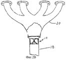
Фиг.2В - разрез подсистемы потока отработавших газов, которая включает устройство настоящего изобретения, выпускной коллектор и выхлопную трубу подсистемы.FIG. 2B is a sectional view of an exhaust gas flow subsystem that includes a device of the present invention, an exhaust manifold, and an exhaust pipe of a subsystem.
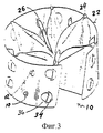
Фиг.3 - устройство настоящего изобретения (общий вид).Figure 3 - device of the present invention (General view).
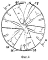
Фиг.4 - устройство настоящего изобретения (вид сверху).Figure 4 - device of the present invention (top view).
Фиг.5 - устройство настоящего изобретения (вид сбоку, отображающий открытую боковую часть корпуса изобретения).5 is a device of the present invention (side view showing the open side of the housing of the invention).
Фиг.6 - устройство настоящего изобретения (продольное сечение по оси 6-6 Фиг.4).6 is a device of the present invention (longitudinal section along the axis 6-6 of Figure 4).
Фиг.7 - характерная лопасть устройства настоящего изобретения (вид сбоку сверху).7 is a characteristic blade of the device of the present invention (side view from above).
Фиг.8 - характерная лопасть устройства настоящего изобретения (вид сверху).Fig - characteristic blade of the device of the present invention (top view).
Фиг.9 - характерная лопасть устройства настоящего изобретения (вид сзади, отображающий изогнутую нижнюю конечную часть лопасти и поток текучей среды, проходящий и направленный непосредственно на этот участок).Fig.9 is a characteristic blade of the device of the present invention (rear view showing the curved lower end part of the blade and the fluid flow passing and directed directly to this section).
Фиг.10 - характерная вторичная лопасть устройства настоящего изобретения (вид сбоку сверху).Figure 10 - characteristic secondary blade of the device of the present invention (side view from above).
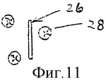
Фиг.11 - характерная вторичная лопасть устройства настоящего изобретения (вид сверху).11 is a characteristic secondary blade of the device of the present invention (top view).
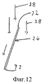
Фиг.12 - характерная вторичная лопасть устройства настоящего изобретения (вид сзади, отображающий поток текучей среды, проходящий и направленный непосредственно на этот участок).12 is a characteristic secondary blade of the device of the present invention (rear view showing the fluid flow passing and directed directly to this section).
Предпочтительный вариант исполнения.The preferred embodiment.
На чертежах завихряющее устройство настоящего изобретения обозначается цифрой 10. Устройство 10 имеет размеры, обеспечивающие его установку внутри канала впуска или канала 12 подсистемы впуска 14 двигателя внутреннего сгорания (не показан). Канал 12 ведет к подсистеме впуска топлива 16, которая в свою очередь может быть инжекторной подсистемой, как показано, или карбюратором. Таким образом, канал используется для поступления воздуха в инжекторную подсистему 16 из блока воздушного фильтра 88.In the drawings, the swirl device of the present invention is indicated by the
На фиг.2А отображено устройство 10, установленное в канале выпуска отработавших газов или в приемной трубе 90. Приемная труба 90 соединена с каталитическим конвертером (катализатор), в который поступают отработавшие газы из глушителя (не показан) и двигателя (не показан). Устройство обеспечивает завихрение отработавших газов, что приводит к образованию вихревого потока и удалению, таким образом, отработавших газов из системы выпуска.FIG. 2A shows a
На фиг.2В отображено устройство 10, установленное в другом типе канала выпуска отработавших газов или в приемной трубе 18. Приемная труба 18 соединена с выпускным коллектором 20, в который поступают отработавшие газы из выпускного канала (не показан) и камеры сгорания двигателя (не показано).FIG. 2B shows a
Устройство 10 изготавливается различных размеров с тем, чтобы оно устанавливалось в каналы впуска различных размеров, различных производителей и моделей автомашин. Устройство включает в себя корпус 22, который имеет предпочтительно цилиндрическую форму для его установки в стандартные каналы впуска, которые имеют аналогичную цилиндрическую форму.The
Однако также могут использоваться другие формы корпуса для установки в каналы впуска, имеющие другие формы.However, other housing shapes may also be used for installation in intake ducts having other shapes.
Устройство 10 включает в себя комплект первичных лопастей 24 и комплект вторичных лопастей 26 для обеспечения генерации завихрения впускного или выпускного потока текучей среды 28, проходящего через канал 12, канал 90 или канал 18. Лопасти 24 и 26 установлены в корпусе 22. Более детально, лопасти 24 и 26 крепятся на стенках 30 корпуса 22 таким образом, что они направлены к центральной области 32 корпуса 22. Лопасти 24 и 26 устанавливаются в отверстия 34, расположенные на стенках 30 по всему корпусу. В отверстия 34 устанавливаются шпонки 36, находящиеся на задней части 38 лопастей 24. Аналогично, лопасти 26 устанавливаются в отверстия 40, расположенные на стенках 30 по всему корпусу.The
Аналогично, в отверстия 40 устанавливаются шпонки 42, находящиеся на задней части 44 лопастей 26. Шпонки 36 и 42 загибаются по наружной поверхности 46 корпуса 22 и привариваются к ней. Однако, если необходимо, то можно также использовать другие подходящие средства крепления лопастей 24 и 26 к корпусу 22. Таким образом, лопасти 24 и 26 устанавливаются в корпусе 22 и находятся в потоке текучей среды 28, проходящем по каналу 12 или 18.Similarly, the
Как показано на фигурах 9 и 12, верхние кромки 52 и 66 лопастей 24 - несоосны с нижними кромками 68, а верхние кромки 72 лопастей 26 - несоосны с нижними кромками 92. Эта несоосность определяется направлением потока текучей среды 28 (или продольно корпусу 22).As shown in figures 9 and 12, the
Лопасти 24 устанавливаются под углом таким образом, чтобы планарные наружные поверхности 46 были направлены на поток текучей среды 28. Аналогично, лопасти 26 устанавливаются под углом таким образом, чтобы планарные наружные поверхности 74 были направлены на поток текучей среды 28. Поток текучей среды 28, сталкиваясь с поверхностью 48 и поверхностью 74, отклоняется в сторону. Лопасти 24 и 26 устанавливаются под углом двадцать пять градусов по отношению к оси 50 корпуса 22. Более детально, угловая ориентация лопастей 24 по отношению к плоскости, которая включает ось 50 и верхнюю кромку 52 конкретной лопасти 24. Аналогично, угловая ориентация лопастей 26 по отношению к плоскости, которая включает ось 50 и верхнюю кромку 72 конкретной лопасти 26. Так как ось 50 совпадает с направлением потока текучей среды 28, то угловая ориентация производится относительно направления потока текучей среды 28, поступающего в корпус 22. Лопасти 24 и 26 также ориентируются под углом, который имеет направление по часовой стрелке от оси потока текучей среды 28, поступающего в корпус 22. Таким образом, посредством такой специфической ориентации лопастей 24 и 26 происходит отклонение потока текучей среды 28 в сторону, то есть по существу происходит закручивание и вращение потока в направлении по часовой стрелке. Это вращательное движение потока текучей среды по часовой стрелке приводит к имеющему форму спирали движению потока текучей среды 28, который выходит из корпуса 22.The
Первичные лопасти 24 состоят из основных участков 54, внутренних средних участков 82, внешних средних участков 84, внутренних нижних участков 56 и внешних нижних участков 58, которые все являются планарными. Средние участки 82 и 84 изогнуты по кромкам 86 и 68 таким образом, чтобы участки 82 и 84 имели отклонение по горизонтали в направлении по часовой стрелке от оси потока текучей среды, поступающего в корпус 22, относительно плоскости, которая включает верхний край 52 и ось 50 (или направление потока текучей среды 28 в корпусе). Таким образом, нижние участки 82 и 84 ориентируются в том же самом направлении, как и основные участки 54 лопастей 24. Однако, в дополнение к отклонению на двенадцать градусов по отношению к плоскости верхней кромки 52 и оси 50, эти нижние участки загнуты в том же самом направлении, как основные участки 54, как это подробно описано выше.
Точно так же нижние участки 56 и 58 изогнуты по кромкам 60 и 62 таким образом, чтобы части 56 и 58 имели отклонения по горизонтали в направлении по часовой стрелке от оси потока текучей среды, поступающего в корпус 22, относительно плоскости, которая включает верхнюю кромку 52 и ось 50 (или направление потока текучей среды 28 в корпусе). Таким образом, нижние средние участки 82 и 84 и нижние участки 56 и 58, ориентируются в том же самом направлении, как и основные участки 54 лопастей 24. Нижние участки 56 и 58 изогнуты под углом двадцать четыре градуса относительно плоскости верхней кромки 52 и оси 50 и также изогнуты в том же самом направлении, как основные участки 54. Таким образом, поток текучей среды, который был отклонен по горизонтали основными участками 54, в дальнейшем отклоняется по горизонтали нижними средними участками 82 и 84 и затем нижними участками 56 и 58. Поток текучей среды 28, который проходит рядом с основными участками 54 и, таким образом, отклоняется от своего первоначального исключительно продольного движения, в горизонтальном направлении, приобретая некоторую степень продольной устойчивости, обеспечиваемой изогнутыми основными участками 54. Эта продольная устойчивость потока текучей среды может быть относительно легко изменена отклонением потока текучей среды с помощью нижних средних участков 82 и 84, нижних участков 56 и 58 в том же самом горизонтальном направлении, таким образом, увеличивая вращательное движение, сообщенное потоку текучей среды 28. Поток текучей среды 28, выходящий из корпуса 22, таким образом, имеет большее завихрение благодаря изогнутым участкам 82, 84, 56 и 58, чем на входе. Последовательное отклонение потока текучей среды 28 в три этапа является более эффективным, чем просто изгиб всей лопасти 24 на тот же самый угол, на который изогнуты нижние участки 56 и 58. Желательно, чтобы направление кромки изгиба 62 было перпендикулярно к направлению потока текучей среды 28.Similarly, the
Целесообразно, чтобы кромки изгиба 60 были наклонены под углом сорок пять градусов относительно направления потока текучей среды 28, в то время как кромки изгиба 86 были наклонены под углом шестьдесят градусов относительно направления потока текучей среды 28.It is advisable that the edges of the
Целесообразно, чтобы лопасти 24 были соединены в задних фронтальных или внутренних участках 78 посредством соединительных элементов 76. Таким образом, лопасти 24 формируются в пары лопастей 24.It is advisable that the
Целесообразно, чтобы соединительные элементы 76 имели боковой изгиб, одновременно оставаясь прямыми в продольном направлении, что придаст им полуцилиндрическую форму. Желательно, чтобы соединительные элементы 76 были ориентированы под углом двадцать пять градусов относительно плоскости, включающей верхнюю кромку 52 и ось 50, как для лопастей 24 и 26. Так как соединительные элементы 76 связывают рули 24, обеспечивая им структурную жесткость, нет никакой необходимости в использовании опорного элемента в центре корпуса 22 для фиксации лопастей 24 в центре корпуса и, таким образом, обеспечивая им необходимое крепление. Следовательно, центр корпуса 22 открыт и не препятствует свободному проходу текучей среды через него. Так как центр корпуса, по замыслу, не может включать структуры, которые могут эффективно генерировать завихрение потока текучей среды, то отсутствие центральных структур не понижает эффективность завихрения, генерируемого устройством 10, а, напротив, минимизирует ограничение потока текучей среды в устройстве 10.It is advisable that the connecting
Целесообразно, чтобы лопасти 24 были продольно длиннее в периферийной области корпуса, чем в центральной области 32. Таким образом, задние области 38 лопастей 24 длиннее фронтальных областей 78.It is advisable that the
Более детально, длина фронтальных областей 78 составляет двадцать пять процентов длины задних областей 38. По существу, эта разность в длине сокращает продольную длину лопастей ближе к центральной области, где лопасть 24 менее эффективна в генерации завихрения. Кроме того, передние верхние кромки 66 лопастей 24 изогнуты в направлении потока текучей среды 28, а нижние кромки 68 лопастей 24 также изогнуты в направлении потока текучей среды 28. Кромки 66 и 68 изогнуты навстречу друг другу так, чтобы лопасти были существенно меньшие в центральной области 32, чем в периферийной области. Передние и задние верхние кромки или основные кромки 52 первыми принимают на себя поток текучей среды 28, поэтому форма задней передней кромки 52 плоская, что увеличивает площадь лопасти 24 в периферийной области 64, где лопасти 24 могут более эффективно генерировать завихрение, в то время как передняя основная кромка 66 изогнута по нисходящей, что уменьшает площадь лопасти 24 в центральной области 32, где лопасти 24, соответственно, не могут генерировать завихрение.In more detail, the length of the
Устройство 10 используется в канале впуска 12 для генерации завихрения воздушного потока, выходящего из устройства, но может также использоваться в коллекторе впуска для завихрения потока текучей среды, который включает в себя воздух и топливо. Однако, когда устройство используется в приемной трубе, выхлопной трубе или другой части системы выпуска отработавших газов, устройство 10 также обеспечивает завихрение потока текучей среды, выходящего из устройства, но основная цель применения настоящего устройства состоит не в том, чтобы обеспечить смешивание компонентов текучей среды, а просто модифицировать струю отработавших газов. По существу, устройство 10 обеспечивает вытяжку отработавших газов из системы выпуска отработавших газов.The
Целесообразно, чтобы корпус 22 изготавливался из нержавеющей стали, но также могут использоваться другие подходящие жесткие или эластичные материалы. Лопасти также целесообразно изготавливать из нержавеющей стали, но также могут использоваться другие подходящие жесткие или эластичные материалы.It is advisable that the
Целесообразно, чтобы корпус 22 включал в себя боковой канал 70, который определяет открытую область 80 в боковой части корпуса 22.It is advisable that the
Таким образом, корпус 22 имеет разрыв в боковой стенке, который придает пружинистость или упругость корпусу 22. Эта особенность пружинистости позволяет корпусу устройства иметь более плотную посадку в канале, что снижает вероятность смещения корпуса с требуемого положения в канале.Thus, the
Соответственно обеспечивается, что в соответствии с настоящим изобретением, устройство для завихрения потока текучей среды, проходящего по каналу впуска или системы выпуска отработавших газов двигателя внутреннего сгорания, полностью отвечает целям, сформулированным выше. Необходимо иметь в виду, что все термины, используемые здесь, являются скорее описательными, чем ограничивающими. Хотя настоящее изобретение описано вместе с определенным осуществлением, сформулированным выше, многие альтернативные воплощения, модификации и вариации будут очевидны специалистам в данной области техники на основе описания, сформулированного выше. Соответственно, оно предназначено для включения всех альтернатив, воплощений, модификаций и вариаций в пределах существа и объема изобретения, определенных в формуле изобретения.Accordingly, it is ensured that, in accordance with the present invention, a device for swirling a fluid stream passing through an inlet or exhaust system of an internal combustion engine fully meets the objectives set forth above. It must be borne in mind that all terms used here are more descriptive than limiting. Although the present invention has been described together with the specific embodiment set forth above, many alternative embodiments, modifications and variations will be apparent to those skilled in the art based on the description set forth above. Accordingly, it is intended to include all alternatives, embodiments, modifications and variations within the spirit and scope of the invention defined in the claims.
Claims (38)
Applications Claiming Priority (4)
| Application Number | Priority Date | Filing Date | Title |
|---|---|---|---|
| US29/161,743 USD469781S1 (en) | 2002-06-05 | 2002-06-05 | Engine intake port swirl vanes |
| US29/161.743 | 2002-06-05 | ||
| US10/314,238 US6796296B2 (en) | 2002-06-05 | 2002-12-09 | Fluid swirling device for an internal combustion engine |
| US10/314.238 | 2002-12-09 |
Publications (2)
| Publication Number | Publication Date |
|---|---|
| RU2004135548A RU2004135548A (en) | 2005-09-10 |
| RU2294441C2 true RU2294441C2 (en) | 2007-02-27 |
Family
ID=29738913
Family Applications (1)
| Application Number | Title | Priority Date | Filing Date |
|---|---|---|---|
| RU2004135548/06A RU2294441C2 (en) | 2002-06-05 | 2003-06-05 | Fluid medium swirling device for internal combustion engine (versions) |
Country Status (11)
| Country | Link |
|---|---|
| US (1) | US6796296B2 (en) |
| EP (1) | EP1448878A4 (en) |
| JP (1) | JP4536511B2 (en) |
| KR (1) | KR20050010858A (en) |
| CN (1) | CN1659369A (en) |
| AU (1) | AU2003237869B2 (en) |
| BR (1) | BR0311589A (en) |
| CA (1) | CA2488250C (en) |
| IL (1) | IL165403A (en) |
| RU (1) | RU2294441C2 (en) |
| WO (1) | WO2003104624A2 (en) |
Cited By (2)
| Publication number | Priority date | Publication date | Assignee | Title |
|---|---|---|---|---|
| RU174143U1 (en) * | 2016-12-09 | 2017-10-04 | Сергей Александрович Кожин | Air swirl device for internal combustion engine |
| RU2684142C1 (en) * | 2015-11-19 | 2019-04-04 | Ниссан Мотор Ко., Лтд. | Air intake device for internal combustion engine |
Families Citing this family (92)
| Publication number | Priority date | Publication date | Assignee | Title |
|---|---|---|---|---|
| WO2003004854A1 (en) * | 2001-06-29 | 2003-01-16 | Heru Prasanta Wijaya | Air-stirring blade for an internal combustion engine |
| KR200268794Y1 (en) * | 2001-10-23 | 2002-03-18 | 김세영 | Wing structure of air swirling device for internal combustion engine |
| US20040065375A1 (en) * | 2002-10-07 | 2004-04-08 | Snider John Michael | Constant acceleration and constant hydraulic diameter eliminate pressure loss in internal and external flow |
| US7383919B2 (en) * | 2003-07-17 | 2008-06-10 | Arlasky Performance Inc. | Rotatable propeller driven engine exhaust system |
| US7086498B2 (en) * | 2003-08-25 | 2006-08-08 | Ford Global Technologies, Llc | Noise attenuation device for a vehicle exhaust system |
| US7131514B2 (en) * | 2003-08-25 | 2006-11-07 | Ford Global Technologies, Llc | Noise attenuation device for a vehicle exhaust system |
| US6837213B1 (en) * | 2003-12-15 | 2005-01-04 | David T. Burnett | Power booster fuel saver |
| US7380639B2 (en) * | 2004-10-12 | 2008-06-03 | Arlasky Performance Inc. | Backpressure reducing exhaust system with stationary blade structure |
| GB2420376B (en) * | 2004-11-19 | 2007-08-08 | David Conner | Improvements to the internal combustion engine |
| US7028663B1 (en) | 2005-01-26 | 2006-04-18 | Kim Jay S | Fluid swirling device |
| US7325538B2 (en) * | 2005-04-15 | 2008-02-05 | Darrell S Bean | Versatile vortex air generator and method of installation |
| US7278389B2 (en) * | 2005-04-19 | 2007-10-09 | Murat Kirakosyan | Automobile intake air flow plenum and plenum diverter |
| US20060260869A1 (en) * | 2005-05-18 | 2006-11-23 | Kim Jay S | Muffler having fluid swirling vanes |
| WO2007006086A1 (en) * | 2005-07-08 | 2007-01-18 | Thomas Shirra | Method of and apparatus for exhausting internal combustion engines |
| AU2006269815B2 (en) * | 2005-07-08 | 2011-03-31 | Ng1 Technologies, Llc | Method of and apparatus for exhausting internal combustion engines |
| US7412974B2 (en) * | 2005-12-12 | 2008-08-19 | Gas Gorilla, Llc | Device for enhancing fuel efficiency of internal combustion engines |
| US7556031B2 (en) * | 2005-12-12 | 2009-07-07 | Global Sustainability Technologies, LLC | Device for enhancing fuel efficiency of and/or reducing emissions from internal combustion engines |
| DE202006013247U1 (en) | 2005-12-14 | 2007-09-20 | Dolmar Gmbh | Abgasverwirbler |
| TWM294569U (en) * | 2006-01-24 | 2006-07-21 | Guang-Shiung Luo | Spiral type intake accelerating exhaust manifold structure |
| US7427222B2 (en) * | 2006-04-10 | 2008-09-23 | Edward Auck | Reversion control device for watercraft exhaust system |
| US7533520B2 (en) * | 2006-04-24 | 2009-05-19 | Fleetguard, Inc. | Exhaust aftertreatment mixer with stamped muffler flange |
| TW200743727A (en) * | 2006-05-17 | 2007-12-01 | zhong-yu Yang | Air intake enhancer for engine |
| US7712305B2 (en) * | 2006-08-23 | 2010-05-11 | Universal Silencer, Llc | Exhaust aftertreatment system with spiral mixer |
| WO2008023856A1 (en) * | 2006-08-24 | 2008-02-28 | Deok-Ja Kang | Output augmentation apparatus for automobile engine |
| US7805932B2 (en) * | 2006-09-29 | 2010-10-05 | Perkins Engines Company Limited | Flow assembly for an exhaust system |
| US7255097B1 (en) * | 2006-10-24 | 2007-08-14 | Ching-Tung Huang | Method for increasing performance of automobile and apparatus thereof |
| DE102007019878A1 (en) * | 2007-04-25 | 2008-11-06 | J. Eberspächer GmbH & Co. KG | Mixing and / or evaporating device and associated production method |
| DE102007028449A1 (en) * | 2007-04-25 | 2008-10-30 | J. Eberspächer GmbH & Co. KG | Mixing and / or evaporating device and associated production method |
| DE102007021598B4 (en) * | 2007-05-08 | 2022-10-20 | Bayerische Motoren Werke Aktiengesellschaft | Device for distributing free-flowing additives in exhaust systems |
| WO2008144385A2 (en) * | 2007-05-15 | 2008-11-27 | Donaldson Company, Inc. | Exhaust gas flow device |
| US7797937B2 (en) * | 2007-06-29 | 2010-09-21 | Caterpillar Inc | EGR equipped engine having condensation dispersion device |
| US7451750B1 (en) | 2007-06-29 | 2008-11-18 | Caterpillar Inc. | Condensation reduction device for an EGR equipped system |
| DE102007035226A1 (en) * | 2007-07-25 | 2009-01-29 | J. Eberspächer GmbH & Co. KG | Flow guiding device and thus equipped exhaust system |
| AT504179B1 (en) * | 2007-10-18 | 2009-02-15 | Avl List Gmbh | INTERNAL COMBUSTION ENGINE WITH AN INTAKE SYSTEM |
| KR100948783B1 (en) * | 2007-10-19 | 2010-03-24 | 임봉규 | Apparatus for improving performance of vehicle |
| WO2009054711A1 (en) * | 2007-10-23 | 2009-04-30 | Calderon Magana Salvador Aleja | Fluid router |
| US8939638B2 (en) | 2008-04-21 | 2015-01-27 | Tenneco Automotive Operating Company Inc. | Method for mixing an exhaust gas flow |
| US9095827B2 (en) | 2008-04-21 | 2015-08-04 | Tenneco Automotive Operating Company Inc. | Exhaust gas flow mixer |
| US8397495B2 (en) * | 2008-06-26 | 2013-03-19 | Tenneco Automotive Operating Company Inc. | Exhaust gas additive/treatment system and mixer for use therein |
| TWM346676U (en) * | 2008-07-24 | 2008-12-11 | Chang-Ho Chien | Air introducing apparatus |
| US20100031920A1 (en) * | 2008-08-07 | 2010-02-11 | Chien Chang-Ho | Air Intake Device |
| FR2935742B1 (en) * | 2008-09-08 | 2012-08-10 | Faurecia Sys Echappement | EXHAUST GAS CLEANING ASSEMBLY WITH INPUT DEFLECTOR |
| GB0821089D0 (en) * | 2008-11-19 | 2008-12-24 | Ford Global Tech Llc | A method for improving the performance of a radial compressor |
| US8141538B2 (en) * | 2008-12-12 | 2012-03-27 | Chung-Yu Yang | Intake ducting device for a car engine |
| EP2358982B1 (en) | 2008-12-17 | 2017-11-08 | Donaldson Company, Inc. | Flow device for an exhaust system |
| DE202009001745U1 (en) | 2009-02-11 | 2009-06-10 | Yang, Chung-Yu | Air duct for air intake pipe of a vehicle engine |
| NL2002675C2 (en) * | 2009-03-26 | 2010-09-28 | Gimo Holding B V | VORTEX GENERATOR. |
| US8177498B2 (en) | 2009-04-21 | 2012-05-15 | Ford Global Technologies, Llc | Inlet swirl control for turbochargers |
| DE112009004724A5 (en) * | 2009-04-29 | 2012-08-30 | Fev Gmbh | COMPRESSOR WITH DRUM GENERATOR IN A MOTOR VEHICLE |
| US20100294237A1 (en) * | 2009-05-22 | 2010-11-25 | Daniel Allen Keegan | Air swirling device for fuel injected internal combustion engines |
| US8220444B2 (en) * | 2009-05-27 | 2012-07-17 | Mackson Limited | System for improving the efficiency of an internal combustion engine of a vehicle |
| EP2524123B1 (en) | 2010-01-12 | 2016-11-23 | Donaldson Company, Inc. | Flow device for exhaust treatment system |
| EP2585693B2 (en) | 2010-06-22 | 2020-08-12 | Donaldson Company, Inc. | Dosing and mixing arrangement for use in exhaust aftertreatment |
| US8683791B2 (en) * | 2010-08-20 | 2014-04-01 | Toyota Motor Engineering & Manufacturing North America, Inc. | Method and system for homogenizing exhaust from an engine |
| NL2005274C2 (en) * | 2010-08-26 | 2012-02-28 | Gimo Holding B V | VORTEX GENERATOR. |
| CN102068892B (en) * | 2010-12-19 | 2013-02-20 | 江苏新中环保股份有限公司 | Ammonia spray mixer |
| US20120222643A1 (en) * | 2011-03-01 | 2012-09-06 | Mann+Hummel Gmbh | Swirl guiding acoustic device with an internal coaxially integrated swirl guide structure |
| WO2012155155A1 (en) * | 2011-05-12 | 2012-11-15 | Van Hung Nguyen | The fuel saving intake manifold for combustion engine |
| US8720194B2 (en) | 2012-02-02 | 2014-05-13 | Jafar Salamat | Exhaust evacuation apparatus |
| US8938954B2 (en) | 2012-04-19 | 2015-01-27 | Donaldson Company, Inc. | Integrated exhaust treatment device having compact configuration |
| US20150020509A1 (en) * | 2012-05-18 | 2015-01-22 | Louis A. Belanger | Method and system for maximizing fuel efficiency of an internal combustion engine |
| EP3329987B1 (en) * | 2012-06-15 | 2021-08-04 | Cummins IP, Inc. | Exhaust gas mixer |
| KR101808162B1 (en) * | 2012-08-10 | 2017-12-12 | 테네코 오토모티브 오퍼레이팅 컴파니 인코포레이티드 | Method for mixing an exhaust gas flow |
| US9790836B2 (en) | 2012-11-20 | 2017-10-17 | Tenneco Automotive Operating Company, Inc. | Loose-fill insulation exhaust gas treatment device and methods of manufacturing |
| EP2956233B1 (en) | 2013-02-15 | 2016-12-21 | Donaldson Company, Inc. | Dosing and mixing arrangement for use in exhaust aftertreatment |
| US9555379B2 (en) | 2013-03-13 | 2017-01-31 | Bayer Healthcare Llc | Fluid path set with turbulent mixing chamber, backflow compensator |
| US20150071826A1 (en) * | 2013-05-07 | 2015-03-12 | Tenneco Automotive Operating Company Inc. | Axial flow atomization module with mixing device |
| US20140338768A1 (en) * | 2013-05-15 | 2014-11-20 | Mario Marcic | Device For Inducing A Vortical Fluid Flow |
| US9255504B2 (en) * | 2013-08-16 | 2016-02-09 | Ford Global Technologies, Llc | Exhaust gas mixer and system |
| US9464605B2 (en) * | 2013-08-24 | 2016-10-11 | Lonn M. Peterson | Quad flow torque enhancement flow divider causing improved fuel/air transfer |
| CN105317528A (en) * | 2014-06-27 | 2016-02-10 | 戴思嘉 | Method for emission reduction and energy conservation of automobile |
| CN104632355A (en) * | 2014-12-18 | 2015-05-20 | 林益煌 | Super cyclone type internal and external gas turbine inlet air conversion device and manufacturing method thereof |
| KR101536552B1 (en) * | 2015-03-06 | 2015-07-14 | (주)대명엔지니어링 | Turbulent flow producing device of pipe for heat exchanger |
| CN105443275A (en) * | 2015-12-14 | 2016-03-30 | 重庆博玉天成文化传媒有限责任公司 | Fuel economizer and automobile engine system |
| WO2017152036A1 (en) | 2016-03-03 | 2017-09-08 | Bayer Healthcare Llc | System and method for improved fluid delivery in multi-fluid injector systems |
| US10473021B2 (en) * | 2016-11-29 | 2019-11-12 | Taiwan Semiconductor Manufacturing Company, Ltd. | Exhaust system and method of using |
| US11786652B2 (en) | 2017-08-31 | 2023-10-17 | Bayer Healthcare Llc | System and method for drive member position and fluid injector system mechanical calibration |
| JP2020532336A (en) | 2017-08-31 | 2020-11-12 | バイエル・ヘルスケア・エルエルシーBayer HealthCare LLC | Methods for dynamic pressure control in fluid injector systems |
| JP7346309B2 (en) | 2017-08-31 | 2023-09-19 | バイエル・ヘルスケア・エルエルシー | Fluid path impedance assessment to improve fluid delivery performance |
| AU2018326386B2 (en) | 2017-08-31 | 2024-03-28 | Bayer Healthcare Llc | Fluid injector system volume compensation system and method |
| JP7221885B2 (en) | 2017-08-31 | 2023-02-14 | バイエル・ヘルスケア・エルエルシー | Injector pressure calibration system and method |
| KR101885754B1 (en) * | 2017-10-30 | 2018-08-06 | 이동규 | Absorption generator |
| CN108757153A (en) * | 2018-06-28 | 2018-11-06 | 福州大学 | Variable vortex is oriented to booster |
| DE102019100267A1 (en) * | 2019-01-08 | 2020-07-09 | Eberspächer Exhaust Technology GmbH & Co. KG | Mixer for an exhaust system of an internal combustion engine |
| CN109611191A (en) * | 2019-01-25 | 2019-04-12 | 东莞市鑫亚低碳设备科技有限公司 | Gasoline economizer |
| WO2020180200A1 (en) * | 2019-03-07 | 2020-09-10 | Salan Gheorghe | Device for modifying the flow regime |
| FI128516B (en) * | 2019-05-24 | 2020-06-30 | Proventia Oy | A mixer arrangement and a method of mixing for aftertreatment of exhaust gas |
| US10941692B1 (en) | 2019-11-01 | 2021-03-09 | Tenneco Automotive Operating Company Inc. | Mixer assembly for exhaust aftertreatment system |
| AU2021224642A1 (en) | 2020-02-21 | 2022-09-15 | Bayer Healthcare Llc | Fluid path connectors for medical fluid delivery |
| CN115175726A (en) | 2020-02-28 | 2022-10-11 | 拜耳医药保健有限责任公司 | Fluid mixing kit |
| BR112022023295A2 (en) | 2020-06-18 | 2023-01-17 | Bayer Healthcare Llc | IN-LINE AIR BUBBLE SUSPENSION APPARATUS FOR INJECTOR FLUID PATHWAY ANGIOGRAPHY |
| KR20230132207A (en) * | 2022-03-08 | 2023-09-15 | 이동규 | Vortex Generator |
Family Cites Families (22)
| Publication number | Priority date | Publication date | Assignee | Title |
|---|---|---|---|---|
| FR2265997A1 (en) * | 1974-03-29 | 1975-10-24 | Reissmueller Anton | |
| GB1540232A (en) * | 1975-05-28 | 1979-02-07 | Littlechild D | Inlet valve assembly for an internal combustion engine |
| JPS5231212A (en) * | 1975-09-04 | 1977-03-09 | Mitsubishi Motors Corp | Internal-combustion engine |
| JPS5236219A (en) * | 1975-09-13 | 1977-03-19 | Teruo Kashiwara | Exhaust equipment for internal combustion engine |
| FR2363365A1 (en) * | 1976-09-02 | 1978-03-31 | Gogneau Achille | BREWER-SCREENER-REFINER-DOSER FOR PULVERULENT, LIQUID OR GASEOUS PRODUCTS |
| JPS546415U (en) * | 1977-06-16 | 1979-01-17 | ||
| GB2006873A (en) * | 1977-10-04 | 1979-05-10 | Longo M | Treating Internal Combustion Engine Charges by Adding Water |
| IL54993A0 (en) * | 1978-06-23 | 1978-08-31 | Isaac Agadi And Electra Ltd | Improvements in internal combustion engines |
| DE3218018A1 (en) * | 1982-05-13 | 1983-11-17 | Robert Bosch Gmbh, 7000 Stuttgart | DEVICE FOR IMPROVING THE COMBUSTION IN INTERNAL COMBUSTION ENGINES |
| US4463742A (en) * | 1982-09-21 | 1984-08-07 | Williams Cyril J | Fuel enconomizer |
| US4536356A (en) * | 1983-12-13 | 1985-08-20 | Li Ching C | Carburetor |
| US4729776A (en) | 1987-02-09 | 1988-03-08 | Elliff Howard E | Air swirling device for use in the annular space of air filters on internal combustion engines |
| US4962642A (en) | 1988-05-19 | 1990-10-16 | Kim Sei Y | Air flow system for an internal combustion engine |
| KR920004745Y1 (en) * | 1990-06-12 | 1992-07-18 | 김세영 | Intake revolution device for internal combustion engine |
| AU5130093A (en) * | 1992-09-03 | 1994-03-29 | Suk Ju Yoon | Output enhancing device for internal combustion engine of vehicle |
| US5595157A (en) * | 1993-02-13 | 1997-01-21 | Meddle Alan L | Air guiding device |
| CN1171485A (en) * | 1996-03-18 | 1998-01-28 | 郑宜智 | Gas swirling device for internal combusion engine and its manufacturing method |
| US5947081A (en) * | 1997-08-12 | 1999-09-07 | Kim; Sei Y. | Air flow system for internal combustion engine |
| JP2000008967A (en) * | 1998-06-17 | 2000-01-11 | Nissan Motor Co Ltd | Engine exhaust gas recirculation system |
| US6158412A (en) | 1999-09-21 | 2000-12-12 | Kim; Jay S. | Air turbulence generator of internal combustion engines |
| NL1015888C2 (en) * | 2000-08-08 | 2002-02-12 | Kwang Yang Motor Co | Air feed device for amplifying atomization effect of fuel involves air inlet pipe, opening of which is provided with flow distribution component inserted into it |
| US6257212B1 (en) * | 2000-09-20 | 2001-07-10 | Rudy W. Hammond | Mechanical fuel gasification |
-
2002
- 2002-12-09 US US10/314,238 patent/US6796296B2/en not_active Expired - Fee Related
-
2003
- 2003-06-05 RU RU2004135548/06A patent/RU2294441C2/en not_active IP Right Cessation
- 2003-06-05 CA CA2488250A patent/CA2488250C/en not_active Expired - Fee Related
- 2003-06-05 BR BR0311589-5A patent/BR0311589A/en not_active IP Right Cessation
- 2003-06-05 JP JP2004511670A patent/JP4536511B2/en not_active Expired - Fee Related
- 2003-06-05 CN CN038130785A patent/CN1659369A/en active Pending
- 2003-06-05 AU AU2003237869A patent/AU2003237869B2/en not_active Ceased
- 2003-06-05 WO PCT/US2003/015403 patent/WO2003104624A2/en active Application Filing
- 2003-06-05 KR KR10-2004-7019633A patent/KR20050010858A/en not_active Application Discontinuation
- 2003-06-05 EP EP03736626A patent/EP1448878A4/en not_active Withdrawn
-
2004
- 2004-11-25 IL IL165403A patent/IL165403A/en not_active IP Right Cessation
Cited By (2)
| Publication number | Priority date | Publication date | Assignee | Title |
|---|---|---|---|---|
| RU2684142C1 (en) * | 2015-11-19 | 2019-04-04 | Ниссан Мотор Ко., Лтд. | Air intake device for internal combustion engine |
| RU174143U1 (en) * | 2016-12-09 | 2017-10-04 | Сергей Александрович Кожин | Air swirl device for internal combustion engine |
Also Published As
| Publication number | Publication date |
|---|---|
| BR0311589A (en) | 2005-03-01 |
| AU2003237869A1 (en) | 2003-12-22 |
| JP2005529273A (en) | 2005-09-29 |
| RU2004135548A (en) | 2005-09-10 |
| KR20050010858A (en) | 2005-01-28 |
| CA2488250A1 (en) | 2003-12-18 |
| JP4536511B2 (en) | 2010-09-01 |
| US20030226539A1 (en) | 2003-12-11 |
| CA2488250C (en) | 2010-09-21 |
| US6796296B2 (en) | 2004-09-28 |
| WO2003104624A2 (en) | 2003-12-18 |
| IL165403A0 (en) | 2006-01-15 |
| CN1659369A (en) | 2005-08-24 |
| WO2003104624A3 (en) | 2004-03-04 |
| AU2003237869B2 (en) | 2008-12-04 |
| IL165403A (en) | 2007-09-20 |
| EP1448878A2 (en) | 2004-08-25 |
| EP1448878A4 (en) | 2006-02-01 |
Similar Documents
| Publication | Publication Date | Title |
|---|---|---|
| RU2294441C2 (en) | Fluid medium swirling device for internal combustion engine (versions) | |
| US7028663B1 (en) | Fluid swirling device | |
| KR101771384B1 (en) | Vortex generators for internal combustion engine | |
| US6158412A (en) | Air turbulence generator of internal combustion engines | |
| US6536420B1 (en) | Gas swirling device for internal combustion engine | |
| JP6434749B2 (en) | Exhaust gas recirculation device and engine system including the exhaust gas recirculation device | |
| KR200246432Y1 (en) | A whirl-pool for intake-manifold of an internal-combustion | |
| KR200236914Y1 (en) | Intake air flow generator of internal combustion engine | |
| CA2176129C (en) | Carburettor | |
| KR20190049403A (en) | Absorption generator | |
| US20100294237A1 (en) | Air swirling device for fuel injected internal combustion engines | |
| KR101887000B1 (en) | Air swalling unit for vehicle with improved efficiency | |
| KR102232248B1 (en) | The exaust fumes reduction device for internal combustion engine | |
| KR20200058719A (en) | Apparatus for generating a swirl in an intake and exhaust manifold of an internal combustion engine | |
| KR102208180B1 (en) | Vortex generator for internal combustion engine | |
| KR102591215B1 (en) | Intake and Exhaust System for Power Output of Internal Combustion Engine | |
| KR102529284B1 (en) | Fluid duct device for vehicle capable of reducing air flow resistance | |
| CN216044087U (en) | Gas mixing device and exhaust gas recirculation system | |
| RU2166116C1 (en) | Internal combustion engine fuel-air mixture homogenizer | |
| KR102036163B1 (en) | Improvement of fuel efficiency and generation of eddy-current vortex and fluid activation device | |
| KR200214907Y1 (en) | A device for transmitting vibration by ultrasonic wave of suction air for internal combustion engine | |
| KR102083830B1 (en) | Inhaling acceleration device for an internal combustion engine | |
| KR200274412Y1 (en) | Air Swirling Unit For Mixing Effect of Fuel and Air in Automobiles | |
| SU1629585A1 (en) | Mixing unit for internal combustion engine feed system | |
| KR200412635Y1 (en) | Wing structure of air swirling device for internal combustion engine |
Legal Events
| Date | Code | Title | Description |
|---|---|---|---|
| MM4A | The patent is invalid due to non-payment of fees |
Effective date: 20090606 |