KR20200058719A - Apparatus for generating a swirl in an intake and exhaust manifold of an internal combustion engine - Google Patents
Apparatus for generating a swirl in an intake and exhaust manifold of an internal combustion engine Download PDFInfo
- Publication number
- KR20200058719A KR20200058719A KR1020180143177A KR20180143177A KR20200058719A KR 20200058719 A KR20200058719 A KR 20200058719A KR 1020180143177 A KR1020180143177 A KR 1020180143177A KR 20180143177 A KR20180143177 A KR 20180143177A KR 20200058719 A KR20200058719 A KR 20200058719A
- Authority
- KR
- South Korea
- Prior art keywords
- intake
- vortex
- internal combustion
- combustion engine
- swirl
- Prior art date
Links
Images


Classifications
-
- F—MECHANICAL ENGINEERING; LIGHTING; HEATING; WEAPONS; BLASTING
- F02—COMBUSTION ENGINES; HOT-GAS OR COMBUSTION-PRODUCT ENGINE PLANTS
- F02B—INTERNAL-COMBUSTION PISTON ENGINES; COMBUSTION ENGINES IN GENERAL
- F02B31/00—Modifying induction systems for imparting a rotation to the charge in the cylinder
- F02B31/04—Modifying induction systems for imparting a rotation to the charge in the cylinder by means within the induction channel, e.g. deflectors
-
- F—MECHANICAL ENGINEERING; LIGHTING; HEATING; WEAPONS; BLASTING
- F01—MACHINES OR ENGINES IN GENERAL; ENGINE PLANTS IN GENERAL; STEAM ENGINES
- F01N—GAS-FLOW SILENCERS OR EXHAUST APPARATUS FOR MACHINES OR ENGINES IN GENERAL; GAS-FLOW SILENCERS OR EXHAUST APPARATUS FOR INTERNAL COMBUSTION ENGINES
- F01N1/00—Silencing apparatus characterised by method of silencing
- F01N1/08—Silencing apparatus characterised by method of silencing by reducing exhaust energy by throttling or whirling
- F01N1/12—Silencing apparatus characterised by method of silencing by reducing exhaust energy by throttling or whirling using spirally or helically shaped channels
-
- Y—GENERAL TAGGING OF NEW TECHNOLOGICAL DEVELOPMENTS; GENERAL TAGGING OF CROSS-SECTIONAL TECHNOLOGIES SPANNING OVER SEVERAL SECTIONS OF THE IPC; TECHNICAL SUBJECTS COVERED BY FORMER USPC CROSS-REFERENCE ART COLLECTIONS [XRACs] AND DIGESTS
- Y02—TECHNOLOGIES OR APPLICATIONS FOR MITIGATION OR ADAPTATION AGAINST CLIMATE CHANGE
- Y02T—CLIMATE CHANGE MITIGATION TECHNOLOGIES RELATED TO TRANSPORTATION
- Y02T10/00—Road transport of goods or passengers
- Y02T10/10—Internal combustion engine [ICE] based vehicles
- Y02T10/12—Improving ICE efficiencies
Landscapes
- Engineering & Computer Science (AREA)
- Chemical & Material Sciences (AREA)
- Combustion & Propulsion (AREA)
- Mechanical Engineering (AREA)
- General Engineering & Computer Science (AREA)
- Exhaust Silencers (AREA)
Abstract
Description
본 발명은 내연기관(Internal combustion engine)에서 흡기가 최대한 혼합된 이후애 흡입포트(suction port)를 통해 연소실로 유입되도록 하여 에미션의 안정화를 제공하게 되는 내연기관의 와류 발생 장치에 관한 것으로, 더욱 구체적으로는 내연기관 엔진의 흡기 매니폴드(intake manifold)에 와류를 발생시킬 수 있는 구조를 구비하여 흡기 매니폴드를 통해 실린더의 연소실로 흡기되는 혼합기가 연소실 내에서 와류를 형성할 수 있도록 하여 혼합기가 연소실 내에서 균일하게 분포될 수 있도록 하고, 연료 무화의 촉진 효과를 극대화할 수 있도록 하여 엔진의 저속과 중속 영역에서 출력을 향상시킴으로써 엔진효율을 증대시키며, 공기와 혼합된 연료에 와류를 형성하여 실린더의 연소실 내부로 분사시킴으로써 연소효율을 증가시켜서 불완전 연소된 배기가스의 배출을 감소시킬 뿐만 아니라, 연비를 절감시킬 수 있도록 내연기관의 흡배기 매니폴드에서 와류를 발생시키는 장치에 관한 것이다.The present invention relates to a device for vortex generation of an internal combustion engine that provides stabilization of an emission by allowing it to flow into a combustion chamber through a suction port after the intake air is mixed as much as possible in an internal combustion engine. Specifically, a mixer capable of generating vortices in an intake manifold of an internal combustion engine engine is provided so that a mixer that is inhaled into a combustion chamber of a cylinder through an intake manifold allows a vortex to form in the combustion chamber, It can be evenly distributed in the combustion chamber, maximizes the effect of accelerating fuel atomization, and improves engine efficiency by improving power in the low and medium speed areas of the engine, and forms a vortex in the fuel mixed with air to form a cylinder It relates to an apparatus for generating vortices in an intake and exhaust manifold of an internal combustion engine to increase the combustion efficiency by injecting into the combustion chamber of the engine, thereby reducing emission of incompletely burned exhaust gas and reducing fuel consumption.
내연기관은 엔진 내부에서 연료를 연소시켜서 열에너지를 기계적 에너지로 전환하여 차량에 동력을 제공하는 장치로써, 사용하는 연료에 의해 가스기관, 가솔린기관, 디젤기관 등으로 분류된다.An internal combustion engine is a device that provides power to a vehicle by converting thermal energy into mechanical energy by burning fuel inside the engine, and is classified into a gas engine, a gasoline engine, and a diesel engine by the fuel used.
엔진의 흡기 계통은 외부에서 유입되는 공기를 여과하는 에어 클리너와, 여과되어 유입되는 공기의 량을 조절하는 트로틀 바디(throttle body)와, 상기 트로틀 바디로부터 유입되는 공기를 일시 저장하는 서지 탱크(surge tank)와, 상기 서지 탱크와 실린더 헤드의 연소실을 연통시키는 흡기 매니폴드로 이루어진다.The intake system of the engine includes an air cleaner that filters air introduced from the outside, a throttle body that controls the amount of air that is filtered and flows in, and a surge tank that temporarily stores air flowing in from the throttle body. tank) and an intake manifold for communicating the surge tank and the combustion chamber of the cylinder head.
이에 따라 외부의 공기는 에어 클리너에서 통과되어 트로틀 바디로 유입되며, 상기 트로틀 바디로 유입된 공기는 트로틀 밸브(throttle valve)에 의해 그 흡기량이 조절되어 서지 탱크에 유입되며, 서지 탱크에 유입된 공기는 흡기밸브의 열림시 부압에 의하여 실린더 헤드의 연소실에 유입되면서 연료와 혼합되어 연소되는 구조로 되어 있다.Accordingly, the outside air passes through the air cleaner and flows into the throttle body, and the air introduced into the throttle body is regulated by the throttle valve to enter the surge tank, and the intake air is introduced into the surge tank. Is a structure that is mixed with fuel and burned while entering the combustion chamber of the cylinder head due to negative pressure when the intake valve is opened.
이러한 내연기관은 외부에서 유입된 공기에 연료가 혼합된 흡기의 흡기량을 트로틀 바디로 조절하여 연소실에 유입되는 흡기의 유입량을 조절함으로써 엔진의 폭발력을 조절하여 출력을 제어하게 되는데, 흡입포트를 통해 연소실 내부로 연료가 분사되기 때문에 연료와 공기가 적절하게 혼합되지 않음은 물론 배기포트(exhaust port) 측으로 연료가 분포되지 않아 탄화수소(HC), 일산화탄소(CO), 산화질소(NOx)등의 불완전연소된 배기가스가 배기포트를 통해 외부로 배출되어 대기를 오염시킬 뿐만 아니라, 엔진의 출력을 저하시키고 연료의 낭비를 초래하게 된다.The internal combustion engine controls the output power by controlling the explosive power of the engine by controlling the intake amount of the intake air flowing into the combustion chamber by controlling the intake amount of the intake air mixed with fuel from the outside with a throttle body. Because fuel is injected into the inside, fuel and air are not properly mixed, and fuel is not distributed to the exhaust port, resulting in incomplete combustion such as hydrocarbon (HC), carbon monoxide (CO), and nitrogen oxide (NOx). Exhaust gas is discharged to the outside through the exhaust port, not only polluting the atmosphere, but also lowering the power of the engine and causing waste of fuel.
특히 트로틀 바디를 통하여 서지 탱크의 챔버로 흡입된 후, 이 챔버의 일측에 그 흐름방향에 대해 수직으로 일렬로 배치된 다수의 흡기 매니폴드로 흡기를 분배하게 된다.In particular, after being sucked into the chamber of the surge tank through the throttle body, intake is distributed to a plurality of intake manifolds arranged in a line perpendicular to the flow direction on one side of the chamber.
그러나 이와 같은 종래의 엔진 흡기장치의 경우, 서지 탱크로 흡입되는 흡기가 흡기 매니폴드의 흡입 포트가 그 흐름방향에 대해 수직으로 일렬로 배열되어 있음으로 서지 탱크로 흡입되는 흡기가 각 매니폴드에 균등하게 공급되지 못하여, 연소실의 연소 효율을 떨어트림과 동시에 그에 따른 배출가스도 증가한다는 문제점이 있다.However, in the case of such a conventional engine intake system, the intake air sucked into the surge tank is arranged in a line perpendicular to the flow direction of the intake manifold, so that the intake air drawn into the surge tank is equal to each manifold. Since it is not supplied, there is a problem that the combustion efficiency of the combustion chamber decreases and the emission gas increases accordingly.
한편, 내연기관의 실린더에서 폭발행정 이후에 공기가 배출되는 배기 매니폴드(Exhaust manifold)의 출구측에 설치되는 배기구에는 내연기관에서 발생되는 소음을 줄이기 위한 장치로 배기 머플러(Exhaust muffler)가 된다.On the other hand, an exhaust muffler is an apparatus for reducing noise generated in an internal combustion engine at an exhaust port installed at an outlet side of an exhaust manifold through which air is discharged after an explosion stroke in a cylinder of an internal combustion engine.
여기서 배기 머플러의 소음감소 효과를 높이게 되면, 배기의 흐름에 대한 저항이 증가되어 엔진의 출력을 저하시키는 문제가 발생한다. 따라서 차량의 설계자는 소음감소 효과와 엔진의 출력 사이의 균형을 고려할 필요가 있으며, 소음감소 효과를 만족시키면서도 배기의 흐름 저항을 감소시켜 엔진의 출력 감소를 방지하는 기술이 필요하게 된다.Here, when the noise reduction effect of the exhaust muffler is increased, a resistance to the flow of the exhaust is increased, which causes a problem of deteriorating the engine output. Therefore, the designer of the vehicle needs to consider the balance between the noise reduction effect and the engine output, and a technique for reducing the flow resistance of the exhaust while preventing the reduction of the engine output is required while satisfying the noise reduction effect.
위와 같이 배기의 흐름 저항을 감소시키기 위하여 트로틀 바디에서와 같이 배기 매니폴드에서 배기의 흐름 방향으로 와류를 형성시켜 주면 배기의 흐름을 빠르게 하여 저항을 감소시킴으로써 엔진의 출력 감소를 방지할 수 있게 된다.In order to reduce the flow resistance of the exhaust as described above, if a vortex is formed in the exhaust flow direction from the exhaust manifold as in the throttle body, the output of the engine can be prevented by reducing the resistance by speeding up the flow of exhaust.
위와 같이 엔진의 연소실로 흡입되고 배출되는 흡배기의 흐름 상태는 엔진의 출력과 에미션 및 연비에 큰 영향을 주게 된다.As described above, the flow state of the intake and exhaust which is sucked in and discharged into the combustion chamber of the engine has a great influence on the engine output, emission and fuel economy.
이에 따라, 엔진의 흡기 계통은 흡입 공기의 흐름 저항이 최소가 되도록 하면서, 또한 엔진의 운전 조건에 따라 이에 알맞은 흡기와 배기가 이루어지도록 하는 것이 바람직하다.Accordingly, it is preferable that the intake system of the engine ensures that the flow resistance of the intake air is minimized, and that intake and exhaust suitable for this are made according to the operating conditions of the engine.
내연기관에서 트로틀 바디를 통과하여 엔진의 연소실로 유입되는 공기의 흐름에 와류를 형성시켜주면 엔진 출력이 증대되고 연비를 개선하는 효과가 있는 것임은 자명한 사실이며, 이를 위하여 내연기관에 흡입되는 공기에 와류를 형성시키기 위한 다양한 장치가 알려져 있다.It is obvious that the engine output is increased and the fuel efficiency is improved by forming a vortex in the flow of air flowing through the throttle body from the internal combustion engine to the combustion chamber of the engine. Various devices are known for forming eddy currents.
이러한 장치들의 일례로 '내연기관의 흡기 와류 장치'가 도 1에 예시되어 있다. 이 도면을 참조하면 강철판을 파발하여 형성되는 고정단부(100)로부터 중앙의 통공(101)을 향하여 경사지게 고정되는 다수개의 고정날개(102)를 일정한 각도로 절곡 형성하여 와류가 형성되게 하는 것인데, 이러한 구조에서는 유입되는 공기가 고정날개(102)에 충돌하면서 공기의 흐름에 저항이 발생하여 출력 향상을 저해하고 진동과 소음을 유발시키게 된다.As an example of such devices, an 'intake vortex device of an internal combustion engine' is illustrated in FIG. 1. Referring to this drawing, a plurality of
이와 달리 와류를 형성하는 날개가 회전이 되게하여 공기의 마찰 저항을 감소시키는 '내연기관의 흡배기 와류 장치'가 알려져 있다.On the other hand, an 'intake / exhaust vortex device of an internal combustion engine' is known in which a blade forming a vortex is rotated to reduce frictional resistance of air.
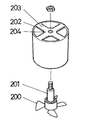
이 장치는 도 2에서 보듯이 와류를 형성하는 날개(200)가 흡기의 유입로 중앙에 놓여지는 고정축(201)에 고정되는 프로펠러 방식으로 되어 흡기의 마찰 저항을 감소시킬 수 있다는 점에 있어서 효용성을 찾아볼 수 있다. 그러나 와류를 형성하는 날개(200)가 흡기 유입로 중앙의 고정축(201)에 고정되기 위해서는 일차적으로 고정축(201)을 고정시키는 구조가 흡기 유입로에 형성되어야 하는데, 이를 위하여 원형관(202)의 내측면으로부터 중앙을 향하여 3~4개의 리브(203)가 교차하는 중앙부에 축을 고정하기 위한 보스(204)가 형성되고 있다. 이러한 구조는 와류를 발생시키는 날개에서는 흡기의 마찰 저항을 감소시킬 수 있지만, 날개를 설치하기 위한 리브(203)와 보스(204)의 구조에서 또다른 흡기의 마찰 저항이 발생하게 되며, 또한 원형관을 흡기 유입로에 삽입하는 구조는 설치와 분리가 곤란한 문제점이 있다.As shown in FIG. 2, this device is effective in that the
한편 내연기관의 와류는 흡배기관 내에서 공기 흐름에 저항이 발생될 수 있으므로 효율을 향상시키기 위해서는 와류가 충분히 형성됨과 동시에 흡배기 공기 흐름의 기류가 신속하게 이동할 수 있어야 한다.On the other hand, since the vortex of the internal combustion engine may generate resistance to the air flow in the intake and exhaust pipe, in order to improve efficiency, the vortex is sufficiently formed and at the same time, the air flow of the intake and exhaust air flow must be able to move quickly.
본 발명의 목적은 종래의 흡기 와류 장치의 문제점을 해여 내연기관 엔진의 흡기 매니폴드에서 효과적으로 와류를 발생시킬 수 있도록 하여 흡기가 최대한 혼합된 이후애 흡입포트를 통해 연소실로 유입되도록 함으로써 혼합기가 연소실 내에서 균일하게 분포되어 에미션의 안정화가 이루어지게 되며, 엔진의 저속과 중속 영역에서 출력을 향상시킴으로써 엔진효율과 연소효율을 증대시켜서 불완전 연소된 배기가스의 배출을 감소시킬 수 있도록 내연기관의 흡배기 매니폴드에서 와류를 발생시키는 장치를 제공하고자 하는 것이다.The object of the present invention is to solve the problems of the conventional intake vortex device so that the intake manifold of the internal combustion engine engine can effectively generate vortex so that the intake is mixed as much as possible and then flows into the combustion chamber through the intake port. The distribution is uniformly distributed in the emission, stabilizing the emission, and improving the power in the low and medium speed areas of the engine to increase the engine efficiency and combustion efficiency to reduce the exhaust of incompletely burned exhaust gas so as to reduce the emission of incomplete combustion exhaust gas. It is intended to provide a device for generating vortices in the fold.
본 발명의 다른 목적은 배기 매니폴드에서 배기의 흐름 방향으로 와류를 형성할 수 있게 되어 배기의 흐름을 빠르게 함으로써 엔진의 출력 감소를 방지할 수 있게 되는 내연기관의 흡배기 매니폴드에서 와류를 발생시키는 장치를 제공하고자 하는 것이다.Another object of the present invention is an apparatus for generating vortices in an intake and exhaust manifold of an internal combustion engine that can form a vortex in the flow direction of the exhaust from the exhaust manifold, thereby preventing the engine from being reduced by speeding up the flow of exhaust. Is to provide.
본 발명의 궁극적인 목적은 내연기관의 흡배기관 내에서 발생하는 와류의 흐름을 신속하게 이동시킬 수 있게 되어 흡배기관 내에서 공기흐름에 따르는 저항을 감소시킴으로써 내연기관의 효율을 향상시킬 수 있게 되는 내연기관의 흡배기 매니폴드에서 와류를 발생시키는 장치를 제공하고자 하는 것이다.The ultimate object of the present invention is to be able to quickly move the vortex flow generated in the intake and exhaust pipes of the internal combustion engine, thereby reducing the resistance to air flow in the intake and exhaust pipes, thereby improving the efficiency of the internal combustion engine. It is to provide a device for generating vortices in the intake and exhaust manifold of the engine.
본 발명은 흡입포트 일측에 서지탱크로 부터 공기를 유입시키는 흡기 매니폴드가 연결되고, 상기 흡기포트와 흡기 매니폴드의 경계 부위에는 연소실내에 공기를 난류로 분사시켜 완전연소 가스를 배출시킬 수 있게 되는 와류 유도 부재에 의해 의해 달성된다.In the present invention, an intake manifold for introducing air from a surge tank to one side of a suction port is connected, and a boundary portion between the intake port and the intake manifold is capable of discharging completely combusted gas by injecting air into the combustion chamber with turbulent flow. This is achieved by a vortex inducing member.
이와 같은 본 발명이 의도하는 목적을 달성하기 위한 기술적인 특징은 내연기관에서 와류를 발생시켜서 연소효율을 개선할 수 있게 되는 흡기 와류 장치에 있어서, 흡기관 내부에 나선형의 나선부가 연속적으로 형성되는 와류유도부재가 형성되는 것을 특징으로 한다.Technical features for achieving the intended purpose of the present invention in the intake vortex device that can improve the combustion efficiency by generating a vortex in an internal combustion engine, the spiral helical portion is continuously formed inside the intake pipe Characterized in that the induction member is formed.
본 발명의 기술적 특징에 따라 상기 와류유도부재가 나선부의 외주면이 흡기관의 내주면에 접촉되는 것을 특징으로 한다.According to the technical features of the present invention, the vortex-inducing member is characterized in that the outer circumferential surface of the spiral part contacts the inner circumferential surface of the intake pipe.
본 발명의 기술적 특징에 따라 상기 와류유도부재의 나선부는 축방향 중심에 동축방향으로 나선부의 나선형을 따라 나선형의 내주면이 형성되어 나선부에 의해 형성되는 와류 흡기의 중심부에 직류의 흡기가 형성되는 것을 특징으로 한다.According to the technical features of the present invention, the spiral portion of the vortex-inducing member is formed with an inner circumferential surface of the spiral along the spiral of the spiral in the coaxial direction at the center of the axial direction, so that direct air intake is formed in the center of the vortex intake formed by the spiral portion. It is characterized by.
본 발명의 기술적 특징에 따라 상기 나선형의 내주면을 형성하는 직경은 흡기관 직경의 1/3~1/4배인 것을 특징으로 한다.According to the technical features of the present invention, the diameter forming the inner circumferential surface of the spiral is characterized in that it is 1/3 to 1/4 times the diameter of the intake pipe.
본 발명의 기술적 특징에 따라 상기 와류유도부재는 나선부가 한쪽 전단부로부터 다른 한쪽의 후단부까지 0.8~1.2 회전하도록 형성되는 것을 특징으로 한다.According to the technical features of the present invention, the vortex-inducing member is characterized in that the spiral part is formed to rotate 0.8 to 1.2 from one front end to the other rear end.
본 발명의 기술적 특징에 따라 상기 와류유도부재가 축방향으로 형성되는 길이는 흡기관의 내경이 이루는 길이보다 2~4배로 형성되는 것을 특징으로 한다.According to the technical features of the present invention, the length in which the vortex-inducing member is formed in the axial direction is characterized in that it is formed 2 to 4 times longer than the length formed by the inner diameter of the intake pipe.
이와 같은 본 발명은 내연기관의 흡기 매니폴드에서 서지탱크로부터 흡입포트를 통하여 연소실로 공급되는 공기를 연소실 내에 난류로 분사시킬 수 있도록 와류유도부재를 설치함으로써, 연소실 내부로 연료가 적절하게 혼합된 공기를 분사시킬 수 있게 된다.In the present invention, the air in which the fuel is properly mixed into the combustion chamber is provided by installing a vortex inducing member to inject air supplied from the surge tank through the suction port through the suction port to the combustion chamber in a turbulent flow in the combustion chamber of the internal combustion engine. Can be sprayed.
본 발명은 내연기관의 실린더 연소실로 유입되는 흡기에 공기 저항을 최소화하면서 와류를 발생시켜서 기화된 연료와 공기를 고르게 혼합시켜서 완전 연소가 가능하게 함으로써 와류 생성에 따르는 소음을 방지하고, 연료의 완전연소가 가능함에 따라 탄화수소(HC), 일산화탄소(CO), 산화질소(NOx) 등과 같은 불완전 연소가스의 배출을 감소시킬 수 있어 이에 따라 엔진의 출력을 향상시킬 뿐만 아니라 연비를 향상시키는 효과가 있다.The present invention minimizes air resistance to the intake air flowing into the cylinder combustion chamber of the internal combustion engine, generates vortex, and evenly mixes vaporized fuel and air to enable complete combustion, thereby preventing noise caused by vortex generation and completely burning fuel. As possible, it is possible to reduce the emission of incomplete combustion gas such as hydrocarbon (HC), carbon monoxide (CO), nitrogen oxide (NOx), thereby improving the power of the engine as well as improving fuel efficiency.
또한 내연기관의 흡배기관 내에서 발생하는 와류의 흐름을 신속하게 이동시킬 수 있게 되어 흡배기관 내에서 공기흐름에 따르는 저항을 감소시킴으로써 내연기관의 효율을 향상시킬 수 있는 효과가 있다.In addition, it is possible to rapidly move the vortex flow generated in the intake and exhaust pipes of the internal combustion engine, thereby reducing the resistance caused by air flow in the intake and exhaust pipes, thereby improving the efficiency of the internal combustion engine.
도 1은 종래 와류 발생 장치의 일례를 나타낸 입체도
도 2는 종래 와류 발생 장치의 다른 일례를 나타낸 입체도
도 3은 본 발명에 따르는 제1 실시예의 입체도
도 4는 본 발명에 따르는 제1 실시예의 일부를 절개한 입체도
도 5는 본 발명에 따르는 제1 실시예의 분해 입체도
도 6은 본 발명에 따르는 제1 실시예의 분해 단면도
도 7은 본 발명에 따르는 제1 실시예의 정면도
도 8은 본 발명에 따르는 제2 실시예의 입체도
도 9는 본 발명에 따르는 제2 실시예의 정면도1 is a three-dimensional view showing an example of a conventional vortex generator
Figure 2 is a three-dimensional view showing another example of a conventional vortex generator
3 is a three-dimensional view of the first embodiment according to the present invention
Figure 4 is a three-dimensional cutaway part of the first embodiment according to the present invention
5 is an exploded perspective view of a first embodiment according to the present invention
Figure 6 is an exploded cross-sectional view of the first embodiment according to the present invention
7 is a front view of a first embodiment according to the present invention
8 is a three-dimensional view of a second embodiment according to the present invention
9 is a front view of a second embodiment according to the present invention
본 발명의 특징과 장점은 첨부된 도면에 의하여 설명되는 실시예에 의하여 보다 명확하게 이해될 수 있을 것이다.Features and advantages of the present invention will be more clearly understood by the embodiments described by the accompanying drawings.
본 발명의 실시예를 설명하기 전에, 다음의 실시예에 기재되거나 도면에 도시된 구성요소들의 구성 및 배열에 의해 본 발명의 응용이 제한되는 것이 아니다. 본 발명은 다른 실시예 들로 구현될 수 있고, 다양한 방법으로 수행될 수 있다. 또한, 장치 또는 요소의 방향 등과 같은 용어들에 관하여 실시예에 사용된 표현 및 술어는 단지 본 발명의 설명을 단순화하기 위해 사용되며, 관련된 장치 또는 요소가 단순히 특정 방향을 가져야 함을 나타내거나 의미하지 않는다.Before describing the embodiments of the present invention, the application of the present invention is not limited by the configuration and arrangement of components described in the following embodiments or illustrated in the drawings. The present invention can be implemented in other embodiments and can be performed in a variety of ways. Also, expressions and predicates used in the embodiments with respect to terms such as the direction of the device or element, etc. are only used to simplify the description of the present invention, and do not indicate or mean that the related device or element should simply have a specific direction. Does not.
또한, 본 명세서 및 청구범위에 사용된 용어나 단어는 통상적이거나 사전적인 의미로 한정하여 해석되어서는 아니되며, 발명자가 발명의 용어와 개념을 가장 최선의 방법으로 설명하기 위하여 본 발명의 기술적 사상에 부합하는 의미와 개념에 입각하여 기재한 것으로 해석하여야 한다.In addition, the terms or words used in the present specification and claims should not be interpreted as being limited to ordinary or dictionary meanings, and the technical spirit of the present invention in order for the inventor to explain the terms and concepts of the invention in the best way. It should be interpreted as written based on the meaning and concept.
따라서 본 발명은 제시되는 실시예에 한정되지 않으며, 본 발명이 속하는 기술 분야에서 통상의 지식을 가진 자에 의하여 본 발명의 기술 사상과 아래에 기재될 특허청구범위에 기재된 기술사상의 균등한 범위 내에서 다양한 수정 및 변경이 가능하다.Therefore, the present invention is not limited to the presented embodiments, and is within the equal scope of the technical idea of the present invention and the technical idea described in the claims to be described below by those skilled in the art to which the present invention pertains. Various modifications and changes are possible.
다음에서 본 발명의 실시예를 설명한다.Next, embodiments of the present invention will be described.
본 발명을 설명함에 있어서, 이미 공지된 기능 혹은 구성에 대한 설명은 본 발명의 요지를 명료하게 설명하기 위하여 생략하기로 한다. 또한 공지된 구성에 관하여 도면의 도시와 부호의 기재를 생략하기로 한다.In describing the present invention, descriptions of already known functions or configurations will be omitted to clearly describe the gist of the present invention. In addition, description of drawings and reference numerals will be omitted in relation to known configurations.
도 3은 본 발명에 따르는 제1 실시예의 입체도이고, 도 4는 본 발명에 따르는 제1 실시예의 일부를 절개한 입체도이며, 도 5는 본 발명에 따르는 제1 실시예의 분해 입체도고, 도 6은 본 발명에 따르는 제1 실시예의 분해 단면도이며, 도 7은 본 발명에 따르는 제1 실시예의 정면도를 나타내고 있다.3 is a three-dimensional view of the first embodiment according to the present invention, FIG. 4 is a cut-away view of a part of the first embodiment according to the present invention, and FIG. 5 is an exploded three-dimensional view of the first embodiment according to the present invention, FIG. 6 is an exploded cross-sectional view of the first embodiment according to the present invention, and FIG. 7 shows a front view of the first embodiment according to the present invention.
내연기관을 구성하는 엔진의 흡기 계통은 주지된 바와 같이, 외부에서 유입되는 공기를 여과하는 에어 클리너와, 여과되어 유입되는 공기의 량을 조절하는 트로틀 바디와, 상기 트로틀 바디로부터 유입되는 공기를 일시 저장하는 서지 탱크와, 상기 서지 탱크와 실리더 헤드의 연소실을 연통시키는 흡기 매니폴드로 이루어진다.As is well known, the intake system of the engine constituting the internal combustion engine includes an air cleaner that filters air flowing in from the outside, a throttle body that controls the amount of air that is filtered, and air that flows in from the throttle body. It consists of a surge tank to store, and an intake manifold communicating the surge tank to the combustion chamber of the cylinder head.
이에 따라 외부의 공기는 에어 클리너에서 통과되어 드르틀 바디로 유입되며, 상기 트로틀 바디로 유입된 공기는 트로틀 밸브에 의해 그 흡기량이 조절되어 서지 탱크에 유입되며, 서지 탱크에 유입된 공기는 흡기밸브의 열림시 부압에 의하여 실린더 헤드의 연소실에 유입되면서 연료와 혼합되어 연소되는 구조로 된다.Accordingly, the outside air passes through the air cleaner and flows into the throttle body, and the air introduced into the throttle body is regulated by the throttle valve to enter the surge tank, and the air introduced into the surge tank is introduced into the surge tank. When it is opened, it enters the combustion chamber of the cylinder head due to the negative pressure and is mixed with fuel to burn.
도 1 내지 도 7에서 보는 바와 같이 본 발명의 와류유도부재(30)는 흡기 매니폴드의 흡기관(40)들이 일체로 연결되는 다수의 흡기 매니폴드를 포함하여 이루어지는 엔진의 흡기장치에 설치된다.1 to 7, the
와류유도부재(30)는 나선형의 나선부(300)가 일정한 길이를 가지고 연속적으로 형성되어 흡기 매니폴드의 흡기관(40) 내부에 고정 설치된다.The vortex-inducing
흡기 매니폴드의 흡기관(40) 내부에 고정 설치되는 와류유도부재(30)의 외주면(310)은 흡기관(40)의 내주면(400)에 밀착되도록 접촉된다.The outer
그리고 일정한 길이를 가지고 연속적으로 형성되는 나선형의 나선부(300)는 한쪽 전단부(320)로부터 다른 한쪽의 후단부(330)까지 0.8~1.2 회전되게 형성된다.In addition, the
나선부(300)가 한쪽의 전단부(320)로부터 다른 한쪽의 후단부(330)까지 0.8회전 이하일 경우에는 와류의 발생량이 감소되어 와류발생에 따르는 효과 또한 감소되며, 1.2회전 이상일 경우에는 와류 발생량이 증가되지만 흡기의 유속이 점자 감소되어 의도하는 와류에 의한 효과가 감소된다.When the
또한, 상기 와류유도부재(30)가 한쪽 전단부(320)로부터 다른 한쪽의 후단부(330)까지 축방향으로 형성되는 길이는 흡기관(40)의 내경이 이루는 길이보다 2~4배로 형성되는 것이 바람직하다.In addition, the length in which the vortex-inducing
와류유도부재(30)의 한쪽 전단부(320)로부터 다른 한쪽의 후단부(330)까지 축방향으로 형성되는 길이가 흡기관(40)의 내경이 이루는 길이보다 2배 이하일 경우에는 와류의 발생량이 감소되어 와류발생에 따르는 효과 또한 감소되며, 4배 이상일 경우에는 와류 발생량이 증가되지만 흡기의 유속이 점자 감소되어 의도하는 와류에 의한 효과가 감소된다.When the length formed in the axial direction from one
이와 같은 본 발명의 와류유도부재(30)는 흡기 매니폴드를 통하여 유입되는 흡기에 와류를 형성하여 각각의 연소실로 공급하게 된다.The
따라서, 와류유도부재(30)에 의해 형성되는 와류로 공급되는 흡기는 매니폴드 바디의 캐비티에서 맥동이 방지되고, 매니폴드와 각각의 흡기포트를 통하여 실린더 연소실로 균등하게 배분되며 공급되게 된다.Therefore, the intake air supplied to the vortex formed by the
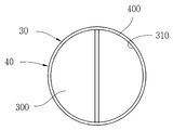
도 8은 본 발명에 따르는 제2 실시예의 입체도이고, 도 9는 본 발명에 따르는 제2 실시예의 정면도를 나타내고 있다.8 is a three-dimensional view of the second embodiment according to the present invention, and FIG. 9 shows a front view of the second embodiment according to the present invention.
도 8 내지 도 9를 참조하면, 와류유도부재(30a)의 나선부(300a)는 축방향 중심에 동축방향으로 나선부(300a)의 나선형을 따라 나선형의 내주면(340)이 형성되어 있다8 to 9, the
상기 나선부(300a)의 외주면(310a)은 흡기관(40a)의 내주면(400a)에 밀착되도록 접촉된다.The outer
축방향 중심에 형성되는 내주면(340)은 와류 흡기의 중심부에 직류의 흡기가 형성되게 한다.The inner
따라서 흡기관(40a) 내부에서 나선부(300a)에 의해 와류가 형성되면서, 그 와류의 중심부에는 직류의 흡기 기류가 형성되어 와류와 직류가 공존하게 된다.Therefore, while the vortex is formed by the
이렇게 형성되는 와류와 직류는 흡기 매니폴드를 통해서 각 실린더 연소실에 분배되는데, 직류의 흡기에 의해 흡기 매니폴드 내에서 발생될 수 있는 공기의 마찰저항을 감소시키고 흡배기의 유속을 빠르게 이동시킬 수 있게 된다.The vortices and direct current thus formed are distributed to the combustion chamber of each cylinder through the intake manifold, which reduces the frictional resistance of air that can be generated in the intake manifold by the intake of direct current and allows the flow rate of the intake and exhaust to move rapidly. .
상기 나선형의 내주면(340)을 형성하는 직경은 흡기관(30a) 직경의 1/3~1/4배로 형성되는 것이 바람직하다.The diameter of the spiral inner
나선형의 내주면(340)을 형성하는 직경이 흡기관(40) 직경의 1/3배 이하일 경우에는 축방향 중심에 형성되는 직류의 기류가 미미하여 빠른 유속에 의한 유입 효과가 감소되며, 1/4배 이상일 경우에는 축방향 중심에 형성되는 직류의 기류가 커지게 되어 공기저항이 일부 감소될 수 있으나, 와류의 발생량이 적어지게 되어 와류발생에 따르는 효과가 감소된다.When the diameter of the inner
앞서 설명한 실시예에서는 본 발명의 와류유도부재(30)가 흡기 매니폴드의 흡기관에 설치되는 경우를 예로 들어 설명하였으나, 배기 매니폴드의 배기관에 설치될 수도 있음은 물론이다.In the above-described embodiment, the case where the
배기 매니폴드의 배기관에 설치되는 와류유도부재 또한, 앞서 설명한 실시예와와 같이 나선부의 외주면이 흡기관의 내주면에 접촉되며, 상기 나선부의 나선형을 따라 나선형의 내주면이 형성되어 나선부에 의해 형성되는 와류 흡기의 중심부에 직류의 흡기가 형성되게 할 수 있다.In addition, the vortex-inducing member installed in the exhaust pipe of the exhaust manifold also has an outer circumferential surface of the spiral portion in contact with the inner circumferential surface of the intake pipe as in the above-described embodiment, and a spiral inner circumferential surface is formed along the spiral of the spiral portion to be formed by the spiral portion Direct air intake may be formed at the center of the vortex intake.
또한, 더 바람직하게 나선형의 내주면을 형성하는 직경은 흡기관 직경의 1/3~1/4배로 형성되고, 와류유도부재가 나선부가 한쪽 전단부로부터 다른 한쪽의 후단부까지 0.8~1.2 회전하도록 형성되며, 와류유도부재가 축방향으로 형성되는 길이는 흡기관의 내경이 이루는 길이보다 2~4배로 형성되는 것을 포함하여 이루어질 수 있다.In addition, more preferably, the diameter of the inner circumferential surface of the spiral is formed to be 1/3 to 1/4 times the diameter of the intake pipe, and the vortex-inducing member is formed so that the spiral part rotates 0.8 to 1.2 from one front end to the other rear end. The length in which the vortex-inducing member is formed in the axial direction may include 2 to 4 times the length formed by the inner diameter of the intake pipe.
지금까지 본 발명에 대하여 바람직한 실시예를 중심으로 살펴보았다.So far, the present invention has been focused on preferred embodiments.
본 명세서에 기재된 실시예와 도면에 도시된 구성은 본 발명의 가장 바람직한 하나의 실시예에 관련된 것이고, 본 발명의 기술적 사상을 모두 대변하는 것은 아니므로, 이들을 대체할 수 있는 다양한 균등물과 변형된 예들이 있을 수 있음을 이해하여야 한다.The embodiments described in the specification and the configuration shown in the drawings are related to one of the most preferred embodiments of the present invention, and do not represent all of the technical spirit of the present invention, and various equivalents and modifications that can replace them It should be understood that there may be examples.
따라서 본 발명은 제시되는 실시예에 한정되지 않으며, 본 발명이 속하는 기술 분야에서 통상의 지식을 가진 자에 의하여 본 발명의 기술 사상과 아래에 기재될 특허청구범위에 기재된 기술사상의 균등한 범위 내에서 다양한 수정 및 변경이 가능한 실시예가 있을 수 있다.Therefore, the present invention is not limited to the presented embodiments, and is within the equal scope of the technical idea of the present invention and the technical idea described in the claims to be described below by those skilled in the art to which the present invention pertains. There may be embodiments in which various modifications and changes are possible.
30, 30a: 와류유도부재 40: 흡기관
300, 30a: 나선부 310, 310a: 외주면
320, 320a: 전단부 330, 330a: 후단부
340: 내주면 400, 400a: 내주면30, 30a: Vortex inducing member 40: Intake pipe
300, 30a: spiral 310, 310a: outer peripheral surface
320, 320a:
340:
Claims (6)
흡기관 내부에 나선형의 나선부가 연속적으로 형성되는 와류유도부재가 형성되는 것을 특징으로 하는 내연기관의 흡배기 매니폴드에서 와류를 발생시키는 장치.
In the intake vortex generating apparatus that can improve the combustion efficiency by generating a vortex in the internal combustion engine,
A device for generating vortices in an intake and exhaust manifold of an internal combustion engine, characterized in that a vortex induction member in which a spiral spiral portion is continuously formed inside the intake pipe.
상기 와류유도부재가 나선부의 외주면이 흡기관의 내주면에 접촉되는 것을 특징으로 하는 내연기관의 흡배기 매니폴드에서 와류를 발생시키는 장치.
According to claim 1,
Device for generating a vortex in the intake and exhaust manifold of an internal combustion engine, characterized in that the vortex inducing member is in contact with the inner circumferential surface of the intake pipe.
상기 와류유도부재의 나선부는 축방향 중심에 동축방향으로 나선부의 나선형을 따라 나선형의 내주면이 형성되어 나선부에 의해 형성되는 와류 흡기의 중심부에 직류의 흡기가 형성되는 것을 특징으로 하는 내연기관의 흡배기 매니폴드에서 와류를 발생시키는 장치.
According to claim 2,
The spiral portion of the vortex-inducing member has an inner circumferential surface of a spiral formed in a axial center along a spiral of the spiral portion, and intake and exhaust of an internal combustion engine characterized in that direct current intake is formed in the center of the vortex intake formed by the spiral portion. A device that generates vortices in the manifold.
상기 나선형의 내주면을 형성하는 직경은 흡기관 직경의 1/3~1/4배인 것을 특징으로 하는 내연기관의 흡배기 매니폴드에서 와류를 발생시키는 장치.
According to claim 3,
Apparatus for generating a vortex in the intake and exhaust manifold of the internal combustion engine, characterized in that the diameter forming the inner peripheral surface of the spiral is 1/3 to 1/4 times the diameter of the intake pipe.
상기 와류유도부재가 나선부가 한쪽 전단부로부터 다른 한쪽의 후단부까지 0.8~1.2 회전하도록 형성되는 것을 특징으로 하는 내연기관의 흡배기 매니폴드에서 와류를 발생시키는 장치.
The method according to any one of claims 1 to 4,
The vortex inducing member is a device for generating a vortex in the intake and exhaust manifold of an internal combustion engine, characterized in that the spiral portion is formed to rotate 0.8 to 1.2 from one front end to the other rear end.
상기 와류유도부재가 축방향으로 형성되는 길이는 흡기관의 내경이 이루는 길이보다 2~4배로 형성되는 것을 특징으로 하는 내연기관의 흡배기 매니폴드에서 와류를 발생시키는 장치.
The method according to any one of claims 1 to 4,
A device for generating a vortex in the intake and exhaust manifold of an internal combustion engine, characterized in that the length in which the vortex inducing member is formed in the axial direction is formed 2 to 4 times longer than the length of the inner diameter of the intake pipe.
Priority Applications (1)
| Application Number | Priority Date | Filing Date | Title |
|---|---|---|---|
| KR1020180143177A KR20200058719A (en) | 2018-11-20 | 2018-11-20 | Apparatus for generating a swirl in an intake and exhaust manifold of an internal combustion engine |
Applications Claiming Priority (1)
| Application Number | Priority Date | Filing Date | Title |
|---|---|---|---|
| KR1020180143177A KR20200058719A (en) | 2018-11-20 | 2018-11-20 | Apparatus for generating a swirl in an intake and exhaust manifold of an internal combustion engine |
Publications (1)
| Publication Number | Publication Date |
|---|---|
| KR20200058719A true KR20200058719A (en) | 2020-05-28 |
Family
ID=70920154
Family Applications (1)
| Application Number | Title | Priority Date | Filing Date |
|---|---|---|---|
| KR1020180143177A KR20200058719A (en) | 2018-11-20 | 2018-11-20 | Apparatus for generating a swirl in an intake and exhaust manifold of an internal combustion engine |
Country Status (1)
| Country | Link |
|---|---|
| KR (1) | KR20200058719A (en) |
Cited By (1)
| Publication number | Priority date | Publication date | Assignee | Title |
|---|---|---|---|---|
| KR20220146257A (en) | 2021-04-23 | 2022-11-01 | 손계동 | Fluid duct device for vehicle capable of reducing air flow resistance |
Citations (2)
| Publication number | Priority date | Publication date | Assignee | Title |
|---|---|---|---|---|
| KR930002880Y1 (en) | 1990-12-28 | 1993-05-24 | 주식회사 금성사 | Keyboard of electrophonic musical instruments |
| KR200263017Y1 (en) | 2001-10-16 | 2002-02-01 | 송철 | device for inspiration eddy of an internal combustion engine |
-
2018
- 2018-11-20 KR KR1020180143177A patent/KR20200058719A/en active IP Right Grant
Patent Citations (2)
| Publication number | Priority date | Publication date | Assignee | Title |
|---|---|---|---|---|
| KR930002880Y1 (en) | 1990-12-28 | 1993-05-24 | 주식회사 금성사 | Keyboard of electrophonic musical instruments |
| KR200263017Y1 (en) | 2001-10-16 | 2002-02-01 | 송철 | device for inspiration eddy of an internal combustion engine |
Cited By (1)
| Publication number | Priority date | Publication date | Assignee | Title |
|---|---|---|---|---|
| KR20220146257A (en) | 2021-04-23 | 2022-11-01 | 손계동 | Fluid duct device for vehicle capable of reducing air flow resistance |
Similar Documents
| Publication | Publication Date | Title |
|---|---|---|
| KR101771384B1 (en) | Vortex generators for internal combustion engine | |
| US7490467B2 (en) | Gas flow enhancer for combustion engines | |
| US7028663B1 (en) | Fluid swirling device | |
| JPWO2006129371A1 (en) | EGR gas mixing device | |
| GB2410296A (en) | Speed increaser for engine intake air | |
| JP3088005U (en) | Intake and exhaust swirl generation blade for internal combustion engine, intake and exhaust swirl generation device for internal combustion engine, and internal combustion engine | |
| KR200246432Y1 (en) | A whirl-pool for intake-manifold of an internal-combustion | |
| KR100757293B1 (en) | Automobile engine output augmentation system | |
| KR20200058719A (en) | Apparatus for generating a swirl in an intake and exhaust manifold of an internal combustion engine | |
| US6701964B1 (en) | Vortex generating airfoil fuel saver | |
| US7464691B2 (en) | Mixing element for creating a vortex motion in an inlet manifold of an internal combustion engine | |
| CN106065808B (en) | A kind of compound tangential inlet duct enhancing engine charge vortex | |
| JP2013204455A (en) | Fuel injection valve | |
| JP2005351235A (en) | Suction device for engine | |
| KR101365892B1 (en) | Air intake duct apparatus capable of improving efficiency of air intake in vehicle | |
| KR19990075276A (en) | Intake air flow increasing device in vehicle engine | |
| KR20120003546A (en) | A fuel economizer of automobile engine | |
| KR100245646B1 (en) | Gasoline-engine mixture vortex generating device | |
| JP2019183791A (en) | Control device for internal combustion engine | |
| KR102529284B1 (en) | Fluid duct device for vehicle capable of reducing air flow resistance | |
| RU12843U1 (en) | DEVICE FOR REDUCING THE TOXICITY OF EXHAUST GASES OF VEHICLES | |
| KR200350212Y1 (en) | Gas-economizing Powerful engine speed increaser | |
| KR200263051Y1 (en) | Wing structure of air swirling device for internal combustion engine | |
| CN2464941Y (en) | Water and fuel vaporization mixing combustion engine with infrared silencer | |
| JP3101741U (en) | Powerful accelerator for engine |
Legal Events
| Date | Code | Title | Description |
|---|---|---|---|
| E701 | Decision to grant or registration of patent right |