RU2070261C1 - Device for joining equipment and shutter board - Google Patents
Device for joining equipment and shutter board Download PDFInfo
- Publication number
- RU2070261C1 RU2070261C1 SU894895331A SU4895331A RU2070261C1 RU 2070261 C1 RU2070261 C1 RU 2070261C1 SU 894895331 A SU894895331 A SU 894895331A SU 4895331 A SU4895331 A SU 4895331A RU 2070261 C1 RU2070261 C1 RU 2070261C1
- Authority
- RU
- Russia
- Prior art keywords
- shelves
- paragraphs
- housing
- fastener
- cross member
- Prior art date
Links
Images

Classifications
-
- E—FIXED CONSTRUCTIONS
- E04—BUILDING
- E04G—SCAFFOLDING; FORMS; SHUTTERING; BUILDING IMPLEMENTS OR AIDS, OR THEIR USE; HANDLING BUILDING MATERIALS ON THE SITE; REPAIRING, BREAKING-UP OR OTHER WORK ON EXISTING BUILDINGS
- E04G17/00—Connecting or other auxiliary members for forms, falsework structures, or shutterings
- E04G17/04—Connecting or fastening means for metallic forming or stiffening elements, e.g. for connecting metallic elements to non-metallic elements
- E04G17/045—Connecting or fastening means for metallic forming or stiffening elements, e.g. for connecting metallic elements to non-metallic elements being tensioned by wedge-shaped elements
-
- E—FIXED CONSTRUCTIONS
- E04—BUILDING
- E04G—SCAFFOLDING; FORMS; SHUTTERING; BUILDING IMPLEMENTS OR AIDS, OR THEIR USE; HANDLING BUILDING MATERIALS ON THE SITE; REPAIRING, BREAKING-UP OR OTHER WORK ON EXISTING BUILDINGS
- E04G7/00—Connections between parts of the scaffold
- E04G7/02—Connections between parts of the scaffold with separate coupling elements
- E04G7/06—Stiff scaffolding clamps for connecting scaffold members of common shape
- E04G7/22—Stiff scaffolding clamps for connecting scaffold members of common shape for scaffold members in end-to-side relation
-
- E—FIXED CONSTRUCTIONS
- E04—BUILDING
- E04G—SCAFFOLDING; FORMS; SHUTTERING; BUILDING IMPLEMENTS OR AIDS, OR THEIR USE; HANDLING BUILDING MATERIALS ON THE SITE; REPAIRING, BREAKING-UP OR OTHER WORK ON EXISTING BUILDINGS
- E04G7/00—Connections between parts of the scaffold
- E04G7/02—Connections between parts of the scaffold with separate coupling elements
- E04G7/26—Connections between parts of the scaffold with separate coupling elements for use with specially-shaped scaffold members
-
- Y—GENERAL TAGGING OF NEW TECHNOLOGICAL DEVELOPMENTS; GENERAL TAGGING OF CROSS-SECTIONAL TECHNOLOGIES SPANNING OVER SEVERAL SECTIONS OF THE IPC; TECHNICAL SUBJECTS COVERED BY FORMER USPC CROSS-REFERENCE ART COLLECTIONS [XRACs] AND DIGESTS
- Y10—TECHNICAL SUBJECTS COVERED BY FORMER USPC
- Y10T—TECHNICAL SUBJECTS COVERED BY FORMER US CLASSIFICATION
- Y10T403/00—Joints and connections
- Y10T403/70—Interfitted members
- Y10T403/7062—Clamped members
- Y10T403/7064—Clamped members by wedge or cam
- Y10T403/7066—Clamped members by wedge or cam having actuator
-
- Y—GENERAL TAGGING OF NEW TECHNOLOGICAL DEVELOPMENTS; GENERAL TAGGING OF CROSS-SECTIONAL TECHNOLOGIES SPANNING OVER SEVERAL SECTIONS OF THE IPC; TECHNICAL SUBJECTS COVERED BY FORMER USPC CROSS-REFERENCE ART COLLECTIONS [XRACs] AND DIGESTS
- Y10—TECHNICAL SUBJECTS COVERED BY FORMER USPC
- Y10T—TECHNICAL SUBJECTS COVERED BY FORMER US CLASSIFICATION
- Y10T403/00—Joints and connections
- Y10T403/71—Rod side to plate or side
- Y10T403/7117—Flanged or grooved rod
-
- Y—GENERAL TAGGING OF NEW TECHNOLOGICAL DEVELOPMENTS; GENERAL TAGGING OF CROSS-SECTIONAL TECHNOLOGIES SPANNING OVER SEVERAL SECTIONS OF THE IPC; TECHNICAL SUBJECTS COVERED BY FORMER USPC CROSS-REFERENCE ART COLLECTIONS [XRACs] AND DIGESTS
- Y10—TECHNICAL SUBJECTS COVERED BY FORMER USPC
- Y10T—TECHNICAL SUBJECTS COVERED BY FORMER US CLASSIFICATION
- Y10T403/00—Joints and connections
- Y10T403/71—Rod side to plate or side
- Y10T403/7182—Yoke or ring-type connector
- Y10T403/7188—Rod received in open channel
Landscapes
- Architecture (AREA)
- Engineering & Computer Science (AREA)
- Mechanical Engineering (AREA)
- Civil Engineering (AREA)
- Structural Engineering (AREA)
- Forms Removed On Construction Sites Or Auxiliary Members Thereof (AREA)
- Joining Of Building Structures In Genera (AREA)
- Connector Housings Or Holding Contact Members (AREA)
- Handcart (AREA)
- External Artificial Organs (AREA)
- Quick-Acting Or Multi-Walled Pipe Joints (AREA)
- Coupling Device And Connection With Printed Circuit (AREA)
- Manufacturing Of Tubular Articles Or Embedded Moulded Articles (AREA)
- Supports Or Holders For Household Use (AREA)
- Casings For Electric Apparatus (AREA)
- Roof Covering Using Slabs Or Stiff Sheets (AREA)
- Adornments (AREA)
- Electrophonic Musical Instruments (AREA)
- Motorcycle And Bicycle Frame (AREA)
- Assembled Shelves (AREA)
- Mutual Connection Of Rods And Tubes (AREA)
- Leg Units, Guards, And Driving Tracks Of Cranes (AREA)
- Patch Boards (AREA)
- Machine Translation (AREA)
- Dry Shavers And Clippers (AREA)
- Pens And Brushes (AREA)
- Stringed Musical Instruments (AREA)
- Seal Device For Vehicle (AREA)
- Tents Or Canopies (AREA)
- Selective Calling Equipment (AREA)
Abstract
Description
Изобретение относится к области строительства и может быть использовано для сборки щитов опалубки. The invention relates to the field of construction and can be used to assemble formwork panels.
Известна опалубка для круглых сооружений, в которых на балках, поддерживающих обшивку, предусмотрен ряд ригелей, регулируемых по длине, причем каждый из ригелей с помощью соединительных элементов крепится к балкам опалубочных щитов и имеет приблизительно U-образное сечение. Эти соединительные элементы на своих U-полках, противоположных опалубке, имеют места крепления для отдельных ригелей. A formwork is known for round structures in which a number of crossbars are provided on the beams supporting the sheathing, each length being adjustable, each of the crossbars being attached to the formwork panel beams and has an approximately U-shaped cross section. These connecting elements on their U-flanges opposite the formwork have attachment points for individual crossbars.
Для присоединения к усиливающим балкам или профилям эти соединительные элементы нуждаются в других соединительных деталях, которые имеют U-образную форму и охватывают усиливающие балки. Крепление таких деталей оснастки, как направленные к основанию упоры, консоли и т.п. с помощью указанных соединительных элементов невозможно, так как они жестко соединены с отдельными ригелями (1). To be connected to reinforcing beams or profiles, these connecting elements need other connecting parts that are U-shaped and enclose the reinforcing beams. Attaching accessories such as stops, consoles, etc. to the base using these connecting elements is impossible, since they are rigidly connected to individual crossbars (1).
Наиболее близким к технической сущности и достигаемому эффекту является приспособление для соединения деталей оснастки с щитами опалубки, включающее закрепленные на стороне, противоположной обшивке щита, усиливающие профильные элементы и корпус U-образного сечения с полками, имеющими узлы крепления деталей оснастки, и с поперечиной, контактирующей с профильными элементами (1). The closest to the technical nature and the achieved effect is a device for connecting parts of tooling with formwork panels, including fastened on the side opposite the sheathing of the shield, reinforcing the profile elements and the U-shaped section with shelves having fastening parts of the tooling, and with a cross member in contact with profile elements (1).
Приспособление снабжено автоматическим фиксатором и U-образным стопором, препятствующим повороту, который расположен на уровне нижней полки, но крепление к повернутой на 90o, то есть к горизонтальной, балке невозможно без соответствующего поворота этого приспособления. Для стоек или т.п. выходящих из приспособления наклонно, это непригодно.The device is equipped with an automatic lock and a U-shaped stopper that prevents rotation, which is located at the level of the lower shelf, but fastening to a 90 ° angle, that is, to a horizontal beam is impossible without a corresponding rotation of this device. For racks or the like coming out of the device obliquely, it is unsuitable.
В основу изобретения положена задача создать приспособление, с помощью которого можно легко и быстро крепить к щитам опалубки любые детали оснастки, например пояса, консоли, упоры и т.п. при этом ориентация усиливающихся ребер или профилей может быть выбрана вертикальной или горизонтальной. The basis of the invention is the task of creating a device with which you can easily and quickly attach to the formwork panels any accessories, for example, belts, consoles, stops, etc. however, the orientation of the reinforcing ribs or profiles can be selected vertical or horizontal.
Приспособление по изобретению снабжено крепежным элементом с Т-образной головкой, которая в определенном положении вводится сквозь прорезь в перемычке усиливающего профильного элемента и после поворота, например, на 90o взаимодействует с кромками прорези. Это обеспечивает быстрое и эффективное соединение между приспособлением и усиливающим профильным элементом, имеющим удлиненное отверстие в перемычке.The device according to the invention is equipped with a fastening element with a T-shaped head, which in a certain position is inserted through the slot in the bridge of the reinforcing profile element and after rotation, for example, by 90 °, interacts with the edges of the slot. This provides a quick and effective connection between the fixture and the reinforcing profile element having an elongated hole in the jumper.
Для предотвращения поворота с помощью уступа на укороченных U-полках достаточно, если уступ имеет ступенчатую форму. To prevent turning with a ledge on shortened U-shelves, it is enough if the ledge has a stepped shape.
Уступ между поперечиной и консолью U-полки может в качестве фиксатора от поворота прилегать к продольной стороне усиливающего профильного элемента и располагается на некотором расстоянии от отверстия для крепежного элемента, которое соответствует расстоянию прорези в усиливающем профильном элементе от края его продольной поверхности. Благодаря этому в обоих повернутых относительно друг друга на 90o положениях автоматически обеспечивается предотвращение поворота приспособления, так как при креплении с помощью крепежного элемента происходит упор в продольную поверхность усиливающего профильного элемента.The ledge between the cross member and the console of the U-shelf can lie against the longitudinal side of the reinforcing profile element as a rotation stopper and is located at a certain distance from the hole for the fastening element, which corresponds to the distance of the slot in the reinforcing profile element from the edge of its longitudinal surface. Due to this, in both positions rotated relative to each other at 90 ° , the device is prevented from turning, since when fastened with a fastening element, an emphasis is placed on the longitudinal surface of the reinforcing profile element.
Предотвращение поворота тем эффективнее, чем лучше прижатие приспособления к усиливающему элементу. Для этого целесообразно, если взаимодействующий с U-поперечиной приспособления контрупор крепежного элемента заклинивается с последним. При этом контрупор может разъемно взаимодействовать со стержнем крепежного элемента. Тем самым он может быть установлен после того, как крепежный элемент и его головка введены в прорезь усиливающего профильного элемента и повернуты. The prevention of rotation is the more effective the better the pressing of the device to the reinforcing element. For this purpose, it is advisable if the counterpart of the fastener interacting with the U-cross member of the device is jammed with the latter. In this case, the counterpart can detachably interact with the rod of the fastener. Thus, it can be installed after the fastener and its head are inserted into the slot of the reinforcing profile element and rotated.
В качестве контрупора могут быть предусмотрены на конце крепежного элемента, противоположном головке, поперечная прорезь через его стержень и вставляемый в нее клин, при этом в рабочем положении поперечная прорезь может достигать отверстия в поперечине приспособления. Благодаря этому контрупор заклинивается, взаимодействия с поперечиной приспособления. Необходимо лишь, чтобы клин был достаточно глубоко вбит, чтобы создать соответствующее растягивающее усилие на стержне и, следовательно, на головке крепежного элемента и поперечине приспособления по отношению к усиливающему профильному элементу. A transverse slot through its shaft and a wedge inserted into it can be provided as a counterpart at the end of the fastening element opposite the head, while in the working position the transverse slot can reach the holes in the cross section of the device. Due to this, the counter-wedge is jammed, the interaction with the cross member of the device. It is only necessary that the wedge is deep enough to drive in to create the corresponding tensile force on the rod and, therefore, on the head of the fastener and the cross member of the device with respect to the reinforcing profile element.
Чтобы длину крепежного элемента и, следовательно, общие размеры приспособления сделать минимальными, целесообразно, если в рабочем положении поперечная прорезь в стержне крепежного элемента располагается между U-полками приспособления со стороны поперечины, противоположной обшивке, а полки приспособления на уровне поперечной прорези имеют отверстия под ключ. Таким образом, клин через эти отверстия можно вставить в поперечную прорезь в стержне крепежного элемента. In order to minimize the length of the fastener and, therefore, the overall dimensions of the fixture, it is advisable if in the working position the transverse slot in the rod of the fastener is located between the U-shelves of the fixture on the side of the cross member opposite the casing, and the shelves of the fixture have key holes at the level of the transverse slot . Thus, the wedge through these holes can be inserted into the transverse slot in the rod of the fastener.
Другой предпочтительный вариант выполнения изобретения состоит в том, что сечение поперечной прорези под клин в стержне крепежного элемента повернуто относительно его Т-образной головки, например, на 45o, а отверстия в полках приспособления расположены со смещением и/или с боковым расширением таким образом, чтобы клин проходил наклонно от одной полки через прорезь в крепежном элементе к другому отверстию. Таким образом, клин забивается наклонно, чтобы он в рабочем положении удерживался еще и силой тяжести. Это не только облегчает монтаж, но и предотвращает непредвиденное расшатывание опалубки.Another preferred embodiment of the invention is that the cross section of the transverse slot for the wedge in the rod of the fastener is rotated relative to its T-shaped head, for example, by 45 o , and the holes in the shelves of the device are offset and / or with lateral expansion in such a way so that the wedge passes obliquely from one shelf through a slot in the fastener to another hole. Thus, the wedge is hammered obliquely, so that it is also held in the working position by gravity. This not only facilitates installation, but also prevents unintended loosening of the formwork.
Еще один вариант изобретения заключается в том, что отверстия под клин в полках приспособления выполнены удлиненными или с рядом расположенных в полках отверстий таким образом, что клин может быть вставлен с обеих сторон с наклоном к поверхности полок, причем по меньшей мере в двух положениях, предпочтительно смещенных относительно друг друга на 90o. Благодаря этому учитывается возможность установки приспособления на усиливающих элементах в двух отличающихся на 90o положениях в зависимости от вертикального или горизонтального расположения этих усиливающих элементов. В каждом таком случае обеспечивается то, что клин проходит наклонно сверху вниз, но не горизонтально, и не снизу вверх.Another variant of the invention is that the holes for the wedge in the shelves of the device are made elongated or with adjacent holes in the shelves in such a way that the wedge can be inserted on both sides with an inclination to the surface of the shelves, at least in two positions, preferably offset from each other by 90 o . Due to this, the possibility of installing the device on the reinforcing elements in two positions differing by 90 ° depending on the vertical or horizontal arrangement of these reinforcing elements is taken into account. In each such case, it is ensured that the wedge passes obliquely from top to bottom, but not horizontally, and not from bottom to top.
Места крепления для разъемного присоединения деталей оснастки могут быть выполнены в виде выемок, предпочтительно в виде отверстий, и расположены в полках приспособления на расстоянии от отверстий под клин. Однако следует заметить, что при необходимости на стержне могут быть предусмотрены резьба и гайка в качестве контрупора, если на полках недостаточно места, с одной стороны, для отверстий под клин и, с другой стороны, для мест крепления. Attachment points for detachable attachment of snap parts can be made in the form of recesses, preferably in the form of holes, and are located in the shelves of the device at a distance from the holes under the wedge. However, it should be noted that, if necessary, a thread and a nut can be provided on the rod as a counter, if there is not enough space on the shelves, on the one hand, for openings under the wedge and, on the other hand, for attachment points.
При этом место крепления может быть предусмотрено на каждой полке и оба места крепления предпочтительно имеют одинаковую форму и соответствующее положение, в частности они могут быть выполнены в виде отверстий для вставного пальца или т. п. Он может быть пропущен сквозь часть детали оснастки, которая располагается между обеими полками, и по обе стороны этой части детали оснастки крепится к полкам. At the same time, a fastening place can be provided on each shelf and both fastening points preferably have the same shape and corresponding position, in particular, they can be made in the form of holes for an inserted finger or the like. It can be passed through a part of the snap-in part, which is located between both shelves, and on both sides of this part of the tool part is attached to the shelves.
Простота и надежность фиксации крепежного элемента приспособления обеспечивается в том случае, если поверхности головки соединительного стержня, обращенные к внутренней стороне пеpемычки усиливающего профиля, выполнены в соответствии с желобчатой формой перемычки усиливающего профильного элемента и проходят с наклоном от стержня наружу. Это одновременно повышает жесткость усиливающего элемента, в результате чего улучшается крепление деталей оснастки с помощью предлагаемого пpиспособления. The simplicity and reliability of fixing the fixture fastener is ensured if the surfaces of the head of the connecting rod facing the inner side of the reinforcement of the reinforcing profile are made in accordance with the grooved shape of the bridge of the reinforcing profile element and extend outward from the rod. This at the same time increases the rigidity of the reinforcing element, as a result of which the fastening of the tooling parts with the help of the proposed device is improved.
Целесообразно, если консоли U-полок выполнены за одно целое с ними. При этом поперечина приспособления может быть вставлена между полками с их консолями, например приварена, а поверхность, в рабочем положении прилегающая к наружной перемычке усиливающего профильного элемента, предпочтительно находится на уровне невыступающих участков полок. Это обеспечивает жесткость конструкции предлагаемого U-образного приспособления. It is advisable if the console U-shelves are made in one piece with them. In this case, the cross member of the device can be inserted between the shelves with their consoles, for example, welded, and the surface, in the working position adjacent to the outer bridge of the reinforcing profile element, is preferably at the level of the protruding sections of the shelves. This provides structural rigidity of the proposed U-shaped device.
Следует еще указать, что отверстие для крепежного элемента предпочтительно представляет собой сверление, так как оно особенно просто в изготовлении и позволяет использовать крепежный элемент с соответственно простым круглым стержнем. Однако при этом стержнеобразный крепежный элемент между его круглым в сечении стержнем и наклонными поверхностями на нижней стороне головки, расположенными крышеобразно, имеет четырехгранный участок, входящий в выемку пеpемычки усиливающего профильного элемента и препятствующий повороту. It should also be noted that the hole for the fastener is preferably a drill, since it is especially easy to manufacture and allows the use of a fastener with a correspondingly simple round rod. However, in this case, the rod-shaped fastening element between its round cross-sectional rod and the inclined surfaces on the lower side of the head, located roof-shaped, has a tetrahedral portion included in the recess of the reinforcing profile element and preventing rotation.
Благодаря этому поперечная прорезь под клин после вставки и фиксации головки крепежного элемента занимает свое положение и тем самым облегчается наклонная вставка клина сбоку. Due to this, the transverse slot under the wedge after inserting and fixing the head of the fastener takes its position and thereby facilitates the inclined insertion of the wedge from the side.
Для уменьшения веса полки приспособления между их торцовыми сторонами и краями, противоположными поперечине, могут быть скошены в зоне вне отверстий под клин и крепежных отверстий для крепления деталей оснастки. To reduce the weight of the shelf, the devices between their end faces and the edges opposite the cross-member can be chamfered in the area outside the holes for the wedge and the mounting holes for fixing the parts of the tooling.
Приспособление позволяет крепить любые детали оснастки к элементам опалубки, которые имеют соответствующие усиливающие ребра или профильные элементы, причем этими деталями оснастки могут быть распорки, ходовые консоли, подъемные консоли, опорные стойки, подпорки или пояса. При этом приспособление допускает его установку в двух положениях, предпочтительно повернутых относительно друг друга на 90o, поэтому оно может быть так ориентировано своими полками и местами крепления, как это необходимо для присоединения деталей оснастки, независимо от того, вертикально или горизонтально расположены усиливающие профильные элементы на опалубочных щитах. Это приспособление можно устанавливать и на опалубке перекрытия с соответствующими усиливающими профильными элементами. При этом в любом положении крепления обеспечивает прочное соединение между деталями оснастки и элементом опалубки, способное не только передавать усилия, но и надежно фиксировать от поворота.The device allows you to attach any parts of the equipment to the formwork elements that have the corresponding reinforcing ribs or profile elements, and these parts of the equipment can be spacers, suspension arms, lifting arms, support legs, supports or belts. At the same time, the device allows its installation in two positions, preferably rotated 90 ° relative to each other, so it can be oriented with its shelves and mounting points as necessary for attaching parts of the equipment, regardless of whether the reinforcing profile elements are vertically or horizontally on shuttering boards. This device can also be installed on the formwork of the floor with the corresponding reinforcing profile elements. At the same time, in any position of fastening, it provides a strong connection between the parts of the equipment and the formwork element, which can not only transmit forces, but also reliably fix it from rotation.
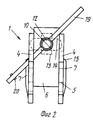
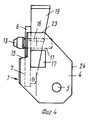
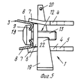
Изобретение поясняется чертежами, где на фиг.1 изображено приспособление перед его монтажом на горизонтальном усиливающем профильном элементе вертикального щита опалубки, фиг.2 вид на приспособление в смонтированном положении, фиг. 3 разрез по поперечине приспособления, фиг.4 - приспособление, ориентированное для установки на профильные элементы, фиг.5 - вид сверху на приспособление в смонтированном положении на вертикальном усиливающем профильном элементе в положении, при котором консоли полок приспособления перекрывают продольные боковые поверхности усиливающего профильного элемента. The invention is illustrated by drawings, in which Fig. 1 shows a fixture before mounting it on a horizontal reinforcing profile element of a vertical formwork shield, Fig. 2 is a view of the fixture in a mounted position, Fig. 3 is a section along the cross-section of the device, FIG. 4 is a device oriented for installation on profile elements, FIG. 5 is a top view of the device in a mounted position on a vertical reinforcing profile element in a position in which the console shelves of the device overlap the longitudinal side surfaces of the reinforcing profile element .
Приспособление 1 предназначено для соединения деталей оснастки, например распорки 2 с щитами опалубки, компенсационными элементами или другими элементами опалубки, которые на чертеже не показаны и которые на стороне, противоположной обшивке, имеют усиливающие профильные элементы 3. Сечение усиливающего профильного элемента 3 показано на фиг.1, а участки, взаимодействующие с приспособлением, представлены на фиг.3-5. The device 1 is intended for connecting snap parts, for example, spacers 2 with formwork panels, compensation elements or other formwork elements, which are not shown in the drawing and which, on the side opposite to the casing, have reinforcing profile elements 3. A section of the reinforcing profile element 3 is shown in FIG. 1, and the sections interacting with the device are presented in FIGS. 3-5.
На фиг.1 и на фиг.5 видно, что приспособление 1 имеет корпус U-образного сечения и его полки 4 снабжены отверстиями 5 для размещения деталей оснастки, например поясов, распорок 2 или т.п. Поперечина 6 в рабочем положении прилегает к усиливающему профильному элементу 3 опалубки. Figure 1 and figure 5 shows that the device 1 has a housing of a U-shaped section and its
Приспособление 1 может быть установлено на профильном элементе 3 в двух различных положениях, смещенных относительно друг друга на 90o, то есть крепление возможно в соответствующем положении на элементах 3, ориентированных с поворотом на 90o относительно друг друга. Одновременно обеспечивается надежная фиксация от поворота приспособления 1 относительно элемента 3.The device 1 can be installed on the profile element 3 in two different positions, offset from each other by 90 o , that is, the mounting is possible in the corresponding position on the elements 3, oriented with a rotation of 90 o relative to each other. At the same time, reliable fixation against rotation of the device 1 relative to the element 3 is provided.
Это достигается тем, что полки 4 корпуса на стороне, обращенной в рабочем положении к обшивке, на части своей длины имеют консоли 7. Эти консоли 7, выступающие за поперечины в обоих смонтированных положениях, играют роль фиксаторов, предотвращающих поворот. Как показано на фиг.3 и 5, консоли 7 могут прилегать к продольной боковой поверхности 8 профильного элемента 3 по кромке или по сгибу на переходе от задней перемычки 9 к продольной боковой поверхности 8 профильного элемента 3. This is achieved by the fact that the
Поперечина 6 приспособления 1 имеет отверстие или выемку 10 для стержня 11 крепежного элемента 12, который снабжен головкой 13, выступающей радиально по меньшей мере в одну сторону (в данном примере на две стороны) за стержень 11. Крепежный элемент 12 головкой 13 вставляется со стороны, противоположной обшивке, в удлиненное отверстие 14 в усиливающем элементе 3 и головка 13 закрепляется там, как показано на фиг.3 и 5. На конце крепежного элемента 12, противоположном головке 13, расположен контрупор для закрепления на U-образном корпусе. The
Таким образом, крепежный элемент 13 для прикрепления приспособления 1 к усиливающему профильному элементу 3 снабжен Т-образной головкой 13, которая при соответствующей ориентации вставляется через удлиненное отверстие 14 в перемычке 9 усиливающего профильного элемента 3 и в данном примере выполнения поворачивается на 90o, взаимодействуя в результате этого с кромками отверстия 14, как показано пунктиром на фиг.2.Thus, the
При сравнении фиг.3-5 видно, что обе полки 4 приспособления 1 имеют консоли 7, которые выступают за поперечину 6 и имеют длину меньше длины полок 4 и образуют с поперечиной 6 ступенчатый уступ (фиг.3 и 4), вне зоны отверстия 10 для крепежного элемента 12. When comparing FIGS. 3-5, it can be seen that both
Как показано на фиг.5, консоли 7 своими продольными плоскостями могут взаимодействовать с продольными сторонами 8 усиливающего профильного элемента 3 с обеспечением фиксации против поворота, если полки 4 и усиливающие профильные элементы 3 имеют соответствующую ориентацию, то в собранном состоянии согласно фиг. 1-3 при положении, повернутом на 90o, уступ 15 между поперечиной 6 и консолями 7 или между невыступающим участком полки 4 и консолью 7 полки 4 служит в качестве фиксатора против поворота, как это показано на фиг. 3. Причем уступы 15 находятся на расстоянии от отверстия 10 для крепежного элемента 12. Благодаря этому в положении, в котором полки 4 приспособления 1 повернуты на 90o относительно продольного направления профильного элемента 3, при установке приспособления на элемент 3 с последним контактируют уступы 15, обеспечивая необходимую фиксацию против поворота.As shown in FIG. 5, the
Контрупор для крепежного элемента 12 необходимо заклинить на поперечине 6 приспособления 1 с помощью крепежного элемента, чтобы приспособление 1 было жестко прижато к элементу 3 и обеспечивалось эффективное предотвращение вращения. При этом предпочтительно, если этот контрупор закрепляется на стержне 11 крепежного элемента разъемно. В данном примере выполнения на конце крепежного элемента 12, противоположном головке 13, в качестве контрупора предусмотрены поперечная прорезь 16 в стержне 11 и вставляемый в нее клин 17, при этом поперечная прорезь 16 в рабочем положении доходит до отверстия 10 в поперечине 6 приспособления. The counter for the
Таким образом, при забивке клина его узкая сторона, обращенная к поперечине 6, контактирует с этой поперечиной, а противоположная узкая сторона оказывает необходимое растягивающее усилие на стержень 11. Thus, when driving a wedge, its narrow side facing the
Чтобы приспособление 1 в целом не было больших размеров и на элемент 3 не воздействовали большие плечи рычагов, в данном примере выполнения прорезь 15 располагается между полками 4, которые на уровне прорези 16 имеют отверстия 17 под клин 19. Причем они проходят в сторону опалубки настолько, что поверхность поперечины 6, противоположная обшивке, в свету лежит в зоне внутреннего контура этих отверстий 17, чтобы клин 19 был прижат к этой поверхности поперечины 6. So that the device 1 as a whole is not large and the element 3 is not affected by the large shoulders of the levers, in this embodiment, the
Клин может прилегать к соответствующим границам этих отверстий 17, например, в том случае, если прорезь 16 не входит в отверстие 10 или даже не достигает его. The wedge may be adjacent to the corresponding boundaries of these
На фиг. 2 показано, что сечение прорези 16 под клин проходит на стержне 11 крепежного элемента 12 под углом 45o к его Т-образной головке 13, а отверстия 17 на полках 4 имеют такое увеличение в поперечном направлении, что клин 19 проходит наклонно от одной полки 4 через прорезь 16 к другой полке 4 и сквозь отверстие 17. Таким образом, при двух возможных вариантах ориентирования приспособления 1 клин 19 располагают с наклоном сверху вниз, что прежде всего облегчает монтаж, так как при вставке клина используется сила тяжести. Кроме того, в рабочем положении благодаря силе тяжести обеспечивается более надежная фиксация и предотвращается непроизвольное выпадение клина 19. Дополнительно на узком конце клина 19 может быть предусмотрен стопорный штифт 20.In FIG. 2 shows that the cross section of the
Увеличение в поперечном направлении отверстий 17, ориентированное вдоль полок 4, таково, что клин 19 может быть вставлен с обеих сторон с наклоном к поверхности полок 4 в двух положениях, смещенных относительно друг друга на 90o, благодаря чему при установке крепежного элемента 12 не нужно обращать внимание на положение прорези 16. Вместо расширенных выемок или отверстий 17 можно предусмотреть расположенные рядом друг с другом несколько отверстий 17, обеспечивающих оба наклонных положения клина 19.The increase in the transverse direction of the
Отверстия 5 в данном примере выполнения приспособления расположены на полках 4 приспособления 1 на расстоянии от отверстий 17. На фиг.1 показано, что на каждой полке 4 предусмотрено одно отверстие 5 и они имеют одинаковые форму и соответствующее друг другу положение, например выполнены в виде отверстий для вставного пальца, который пропускается сквозь соответствующие отверстия 21 в распорке 2, которая вставляется между полками 4. Таким образом, распорка 2 или другая деталь оснастки своим соединительным участком с отверстием 21 вставляется между полками 4 и там закрепляется с помощью вставного пальца, пропущенного сквозь отверстия 5 и 21. Распорка может воспринимать или передавать усилия и моменты от приспособления 1 на профильный элемент 3 без опасности поворота или отклонения или, наоборот, усилия от профильных элементов 3 или опалубочных щитов через приспособление 1 передавать на распорку 2 или т.п. The
Целесообразно, чтобы консоли 7 полок 4 и сами полки представляли собой одну деталь, хотя возможны и другие решения. Поперечина 6 приспособления 1 вставлена между полками 4 и их консолями 7 и приварена, а ее поверхность, прилегающая в рабочем положении к перемычке 9 усиливающего профильного элемента 3, при этом предпочтительно находится на одном уровне с невыступающим участком полок 4 или даже выступает по отношению к нему, как показано на фиг.4. It is advisable that the
Отверстие 10 для крепежного элемента 12 в данном примере выполнения представляет собой сверление, которое проще в изготовлении. The
На фиг. 1 показано, что стержневидный крепежный элемент 9 между своим круглым в сечении стержнем 11 и крышеобразно расположенными поверхностями на нижней стороне головки 13 имеет четырехгранный участок 22, препятствующий повороту в выемке 14 перемычки 9 усиливающего профильного элемента 3. Как наклонные поверхности на головке 13, так и четырехгранный участок 22 служат, таким образом, для стабилизации положения крепежного элемента 12 и, следовательно, клина 19, а также всего приспособления 1, что улучшает передачу усилий и моментов. In FIG. 1 shows that the rod-shaped
Кроме того, на фиг. 1 показано, что полки 4 приспособления 1 между их торцевыми сторонами 23 и кромками 14, противоположными перемычке 8, имеют снаружи отверстий 17 под клин 19 и отверстий 5 для деталей 2 оснастки скосы. Благодаря этому уменьшается вес и сокращаются выступы приспособления 1 относительно профильных элементов 3 или деталей 2 оснастки. In addition, in FIG. 1 shows that the
Приспособление 1 служит для соединения деталей 2 оснастки с щитами опалубки, компенсационными элементами и другими элементами опалубки, которые на своей стороне, противоположной обшивке, снабжены усиливающими профильными элементами 3. Приспособление 1 при этом имеет корпус U-образной формы, причем полки 4 снабжены отверстиями 5 крепления, например отверстиями для деталей 2 оснастки, например поясов, распорок, ходовых консолей и т.п. а поперечина 6 прилегает и прижимается в рабочем положении к усиливающему профильному элементу 3, прежде всего к перемычке 9 этого профиля. По меньшей мере одна полка 4, предпочтительно обе полки, имеет на стороне, обращенной в рабочем положении к обшивке, на части своей длины консоль 7, выступающую за поперечину 6, консоль препятствует повороту и прилегает к продольной боковой поверхности 8 усиливающего профильного элемента 3, то есть к переходу от перемычки 9 к поверхности 8. Поперечина 6 приспособления 1 снабжена по меньшей мере одной (при необходимости открытой со стороны кромки) выемкой или отверстием 10 для крепежного элемента 12, в частности для стержня 4. Благодаря этому приспособление 1 можно закреплять на усиливающем профильном элементе 3 в двух повернутых относительно друг друга на 90o положениях с фиксацией против поворота, в результате чего обеспечивается передача возникающих усилий и моментов.The device 1 is used to connect parts 2 of the equipment with the formwork panels, compensation elements and other formwork elements, which are provided with reinforcing profile elements on their opposite side of the casing 3. The device 1 has a U-shaped body, and the
Вариант выполнения изобретения показан на фиг.5 и 2. Консоли 7 выполнены с небольшим наклоном относительно параллельных полок 4 для обеспечения улучшения контакта с трапециевидной формы усиливающего профильного элемента 3 и сохранения соответствующего наклонного положения в сечении боковой стенки 8 усиливающего профильного элемента 3. При этом внутренние размеры этих наклонных относительно друг друга консолей 7 соответствуют наружным размерам двух продольных стенок 8 усиливающего профильного элемента 3. An embodiment of the invention is shown in FIGS. 5 and 2. The
На чертежах показано, что клин 12 в рабочем положении своим узким концом проходит сквозь отверстие 17 полки, но своим широким концом проходит над торцовой стороной противоположной полки или даже упирается в нее. То есть нет необходимости в том, чтобы клин был пропущен сквозь оба отверстия 17 одновременно, он может проходить только через одно из них. The drawings show that the
Claims (19)
Applications Claiming Priority (3)
| Application Number | Priority Date | Filing Date | Title |
|---|---|---|---|
| DEP3838489.2 | 1988-11-12 | ||
| DE3838489A DE3838489C1 (en) | 1988-11-12 | 1988-11-12 | |
| PCT/DE1989/000675 WO1990005226A1 (en) | 1988-11-12 | 1989-10-23 | Device for joining accessories to switchboards |
Publications (1)
| Publication Number | Publication Date |
|---|---|
| RU2070261C1 true RU2070261C1 (en) | 1996-12-10 |
Family
ID=6367101
Family Applications (1)
| Application Number | Title | Priority Date | Filing Date |
|---|---|---|---|
| SU894895331A RU2070261C1 (en) | 1988-11-12 | 1989-10-23 | Device for joining equipment and shutter board |
Country Status (28)
| Country | Link |
|---|---|
| US (1) | US5265973A (en) |
| EP (1) | EP0369153B1 (en) |
| JP (1) | JPH0656054B2 (en) |
| KR (1) | KR960004046B1 (en) |
| CN (1) | CN1018010B (en) |
| AT (1) | ATE74990T1 (en) |
| AU (1) | AU633519B2 (en) |
| CA (1) | CA2002723C (en) |
| DE (2) | DE3838489C1 (en) |
| DK (1) | DK164825C (en) |
| DZ (1) | DZ1371A1 (en) |
| EG (1) | EG18763A (en) |
| ES (1) | ES2019854T3 (en) |
| FI (1) | FI93981C (en) |
| GR (1) | GR3004401T3 (en) |
| HK (1) | HK17593A (en) |
| HU (1) | HU213696B (en) |
| IL (1) | IL92261A (en) |
| LT (1) | LT3578B (en) |
| LV (1) | LV10801B (en) |
| MA (1) | MA21675A1 (en) |
| MY (1) | MY104472A (en) |
| NO (1) | NO178384C (en) |
| PT (1) | PT92272B (en) |
| RU (1) | RU2070261C1 (en) |
| SG (1) | SG81492G (en) |
| UA (1) | UA32403C2 (en) |
| WO (1) | WO1990005226A1 (en) |
Families Citing this family (10)
| Publication number | Priority date | Publication date | Assignee | Title |
|---|---|---|---|---|
| WO1994027546A1 (en) * | 1993-05-26 | 1994-12-08 | Ricon Corporation | Vehicle lifts |
| ES2130960B1 (en) * | 1996-09-18 | 2000-02-16 | Ulma C Y E S Coop | FRAME AND LATCH FOR MANUPORTABLE FORMWORK PANEL. |
| DE10331359B4 (en) * | 2003-07-11 | 2010-07-15 | Peri Gmbh | Turnbuckle device with inclined wedge |
| DE102004005571B4 (en) * | 2004-02-05 | 2008-07-10 | Daimler Ag | Connection area for connecting an attachment to a vehicle body |
| ES2261103B1 (en) * | 2006-06-21 | 2007-09-16 | Sistemas Tecnicos De Encofrados, S.A. | "COUPLING DEVICE FOR WORK POINTS". |
| CN102402029B (en) * | 2011-11-18 | 2013-11-20 | 深圳市华星光电技术有限公司 | Backplane of liquid crystal module and splicing structure thereof |
| CN103190294A (en) * | 2012-12-31 | 2013-07-10 | 仲恺农业工程学院 | Grafting knife |
| CN106968430A (en) * | 2017-04-13 | 2017-07-21 | 江西省凯骏实业有限公司 | A kind of combinable plastic building template |
| CN108526414A (en) * | 2018-04-23 | 2018-09-14 | 共享装备股份有限公司 | Separate type gripping mechanism |
| US10792535B2 (en) * | 2018-09-11 | 2020-10-06 | Paradigm Health and Wellness | Dip bar for a power cage |
Family Cites Families (14)
| Publication number | Priority date | Publication date | Assignee | Title |
|---|---|---|---|---|
| US330583A (en) | 1885-11-17 | Metallic fence | ||
| FR866489A (en) * | 1940-04-12 | 1941-08-14 | Improvements to three-brush generators | |
| US3004636A (en) * | 1959-03-18 | 1961-10-17 | Flush Metal Partition Corp | Ceiling support member with adjustable hanger bolts |
| FR1300913A (en) * | 1961-06-29 | 1962-08-10 | Feralco Sa | Assembly devices and racks produced using these devices |
| US3330583A (en) * | 1964-05-14 | 1967-07-11 | Bell Telephone Labor Inc | Safety latch |
| US3588026A (en) * | 1968-05-27 | 1971-06-28 | Chester I Williams | Two-stage form-securing system |
| DE2912005C2 (en) * | 1979-03-27 | 1983-12-15 | Josef 7611 Steinach Maier | Device for connecting formwork panels arranged in one plane |
| EP0049096B1 (en) * | 1980-09-29 | 1985-12-27 | Aluma Systems Incorporated | Bolted aluminium shoring frame |
| US4430019A (en) * | 1981-02-04 | 1984-02-07 | Harsco Corporation | Connector assembly |
| DE3119023A1 (en) * | 1981-05-13 | 1982-12-02 | Emil Steidle Gmbh & Co, 7480 Sigmaringen | Concrete shuttering |
| US4439052A (en) * | 1981-06-11 | 1984-03-27 | Stallningsgruppen I Goteborg Aktiebolag | Device for coupling together laterally directed scaffold elements to uprights in a scaffold or the like |
| DE3333619C2 (en) | 1983-09-17 | 1986-05-15 | Josef 7611 Steinach Maier | Formwork for circular buildings |
| DE3432140C2 (en) * | 1984-08-31 | 1994-05-05 | Oesterr Doka Schalung | Formwork element |
| US4786204A (en) * | 1986-02-24 | 1988-11-22 | The Eversman Mfg. Company | Clamping apparatus with bi-directional clamping device |
-
1988
- 1988-11-12 DE DE3838489A patent/DE3838489C1/de not_active Expired
-
1989
- 1989-10-05 EP EP89118469A patent/EP0369153B1/en not_active Expired - Lifetime
- 1989-10-05 ES ES198989118469T patent/ES2019854T3/en not_active Expired - Lifetime
- 1989-10-05 DE DE8989118469T patent/DE58901179D1/en not_active Expired - Lifetime
- 1989-10-05 AT AT89118469T patent/ATE74990T1/en not_active IP Right Cessation
- 1989-10-19 MY MYPI89001453A patent/MY104472A/en unknown
- 1989-10-23 WO PCT/DE1989/000675 patent/WO1990005226A1/en active IP Right Grant
- 1989-10-23 RU SU894895331A patent/RU2070261C1/en active
- 1989-10-23 US US07/679,038 patent/US5265973A/en not_active Expired - Lifetime
- 1989-10-23 HU HU896047A patent/HU213696B/en unknown
- 1989-10-23 UA UA4895331A patent/UA32403C2/en unknown
- 1989-10-23 AU AU43449/89A patent/AU633519B2/en not_active Expired
- 1989-10-23 JP JP1510592A patent/JPH0656054B2/en not_active Expired - Fee Related
- 1989-10-23 KR KR1019900701500A patent/KR960004046B1/en not_active IP Right Cessation
- 1989-11-07 EG EG541/89A patent/EG18763A/en active
- 1989-11-09 IL IL92261A patent/IL92261A/en unknown
- 1989-11-10 MA MA21928A patent/MA21675A1/en unknown
- 1989-11-10 CA CA002002723A patent/CA2002723C/en not_active Expired - Lifetime
- 1989-11-10 CN CN89108476A patent/CN1018010B/en not_active Expired
- 1989-11-10 PT PT92272A patent/PT92272B/en not_active IP Right Cessation
- 1989-11-11 DZ DZ890171A patent/DZ1371A1/en active
-
1991
- 1991-04-30 DK DK080091A patent/DK164825C/en not_active IP Right Cessation
- 1991-05-10 FI FI912300A patent/FI93981C/en not_active IP Right Cessation
- 1991-05-13 NO NO911850A patent/NO178384C/en unknown
-
1992
- 1992-04-17 GR GR910400217T patent/GR3004401T3/el unknown
- 1992-08-13 SG SG814/92A patent/SG81492G/en unknown
-
1993
- 1993-03-04 HK HK175/93A patent/HK17593A/en not_active IP Right Cessation
- 1993-05-21 LV LVP-93-389A patent/LV10801B/en unknown
- 1993-11-05 LT LTIP1440A patent/LT3578B/en not_active IP Right Cessation
Non-Patent Citations (1)
| Title |
|---|
| 1. Патент ФРГ N 3333619, кл. E 04 G 11/20, 1985. 2. Патент США N 3330583, кл. 287-189.36, 1967. * |
Also Published As
Similar Documents
| Publication | Publication Date | Title |
|---|---|---|
| RU2070261C1 (en) | Device for joining equipment and shutter board | |
| DK169357B1 (en) | Arrangement for connecting pillars and beams made of concrete to form the connections in the skeleton structure for buildings and similar constructions | |
| CN108699847B (en) | Side panel, ceiling formwork system with at least one such side panel and method for erecting such a side panel | |
| US6220392B1 (en) | Scaffold with vertical and transverse supports | |
| CN111719846B (en) | Holder for holding an object on a formwork panel | |
| RU2122087C1 (en) | Forms (versions) | |
| US5479754A (en) | Method and apparatus for installing an elevator shaft door | |
| EP0585777B1 (en) | Intermediate member for fixing the guide rails to an elevator shaft | |
| GB2179115A (en) | Construction system | |
| JP4551199B2 (en) | Bracket for bracing member and bracing member | |
| RU2126075C1 (en) | Shuttering panel with at least one post of v-shaped cross-section | |
| JP2019031837A (en) | Stair handrail for temporary scaffolding | |
| PT82459B (en) | COVERING FOR CEILINGS | |
| KR101978804B1 (en) | Safety railing | |
| RU2256044C2 (en) | Connection structure for assembling members of scaffolding and coupling unit and frame thereof | |
| US4858724A (en) | Safety fence for scaffolds | |
| DE3867872D1 (en) | SECURITY PROTECTION AREA FIELD FOR TOOLS. | |
| JP7548738B2 (en) | Structure for mounting gripping member to panel body | |
| KR102657703B1 (en) | safety canopy structure of temporary soundproofing wall | |
| RU2809450C1 (en) | Bracket for installing canopy platform | |
| JPH0712541Y2 (en) | Scaffolding equipment | |
| KR200317313Y1 (en) | equipment for constructing an elevator shaft | |
| JP3542061B2 (en) | Scaffold support | |
| JP3706460B2 (en) | Temporary scaffolding mounting brackets and temporary bases for building components | |
| JP3638761B2 (en) | H-framework scaffold |