KR940002356B1 - 비접촉자동초점위치맞춤방법 및 장치 - Google Patents
비접촉자동초점위치맞춤방법 및 장치 Download PDFInfo
- Publication number
- KR940002356B1 KR940002356B1 KR1019870014764A KR870014764A KR940002356B1 KR 940002356 B1 KR940002356 B1 KR 940002356B1 KR 1019870014764 A KR1019870014764 A KR 1019870014764A KR 870014764 A KR870014764 A KR 870014764A KR 940002356 B1 KR940002356 B1 KR 940002356B1
- Authority
- KR
- South Korea
- Prior art keywords
- light beam
- reflected
- measurement light
- objective lens
- optical
- Prior art date
Links
- 238000000034 method Methods 0.000 title claims description 16
- 230000003287 optical effect Effects 0.000 claims description 120
- 238000005259 measurement Methods 0.000 claims description 111
- 238000003384 imaging method Methods 0.000 claims description 10
- 238000013459 approach Methods 0.000 claims description 8
- 239000004065 semiconductor Substances 0.000 claims description 8
- 230000004907 flux Effects 0.000 claims description 6
- 230000010287 polarization Effects 0.000 claims description 6
- 230000002093 peripheral effect Effects 0.000 claims description 5
- 230000001678 irradiating effect Effects 0.000 claims description 3
- RYGMFSIKBFXOCR-UHFFFAOYSA-N Copper Chemical compound [Cu] RYGMFSIKBFXOCR-UHFFFAOYSA-N 0.000 claims 1
- 229910052802 copper Inorganic materials 0.000 claims 1
- 239000010949 copper Substances 0.000 claims 1
- 230000000694 effects Effects 0.000 description 5
- 238000006073 displacement reaction Methods 0.000 description 4
- 238000012545 processing Methods 0.000 description 4
- 238000001514 detection method Methods 0.000 description 3
- 230000007935 neutral effect Effects 0.000 description 3
- 238000010586 diagram Methods 0.000 description 2
- 239000000758 substrate Substances 0.000 description 2
- 230000005494 condensation Effects 0.000 description 1
- 238000009833 condensation Methods 0.000 description 1
- 239000006059 cover glass Substances 0.000 description 1
- 239000011521 glass Substances 0.000 description 1
- 238000009434 installation Methods 0.000 description 1
- 230000002452 interceptive effect Effects 0.000 description 1
- 239000007788 liquid Substances 0.000 description 1
- 238000011160 research Methods 0.000 description 1
- 238000005070 sampling Methods 0.000 description 1
- 238000004904 shortening Methods 0.000 description 1
- 239000007787 solid Substances 0.000 description 1
Images


Classifications
-
- G—PHYSICS
- G02—OPTICS
- G02B—OPTICAL ELEMENTS, SYSTEMS OR APPARATUS
- G02B7/00—Mountings, adjusting means, or light-tight connections, for optical elements
- G02B7/02—Mountings, adjusting means, or light-tight connections, for optical elements for lenses
- G02B7/04—Mountings, adjusting means, or light-tight connections, for optical elements for lenses with mechanism for focusing or varying magnification
-
- G—PHYSICS
- G02—OPTICS
- G02B—OPTICAL ELEMENTS, SYSTEMS OR APPARATUS
- G02B7/00—Mountings, adjusting means, or light-tight connections, for optical elements
- G02B7/28—Systems for automatic generation of focusing signals
- G02B7/30—Systems for automatic generation of focusing signals using parallactic triangle with a base line
- G02B7/32—Systems for automatic generation of focusing signals using parallactic triangle with a base line using active means, e.g. light emitter
-
- G—PHYSICS
- G01—MEASURING; TESTING
- G01S—RADIO DIRECTION-FINDING; RADIO NAVIGATION; DETERMINING DISTANCE OR VELOCITY BY USE OF RADIO WAVES; LOCATING OR PRESENCE-DETECTING BY USE OF THE REFLECTION OR RERADIATION OF RADIO WAVES; ANALOGOUS ARRANGEMENTS USING OTHER WAVES
- G01S17/00—Systems using the reflection or reradiation of electromagnetic waves other than radio waves, e.g. lidar systems
- G01S17/02—Systems using the reflection of electromagnetic waves other than radio waves
- G01S17/06—Systems determining position data of a target
- G01S17/46—Indirect determination of position data
Landscapes
- Physics & Mathematics (AREA)
- General Physics & Mathematics (AREA)
- Electromagnetism (AREA)
- Engineering & Computer Science (AREA)
- Optics & Photonics (AREA)
- Computer Networks & Wireless Communication (AREA)
- Radar, Positioning & Navigation (AREA)
- Remote Sensing (AREA)
- Automatic Focus Adjustment (AREA)
- Length Measuring Devices By Optical Means (AREA)
- Measurement Of Optical Distance (AREA)
Abstract
Description
Claims (11)
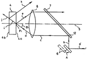
- 광학기구(2)의 광축(5)과 평행하게 발사된 측정광속으로서의 편광 He-Ne레이저광선(a)을 광축에 대해서 45도의 경사각도를 유지하면서 평행이동 자재로운 가동미러(6)에서 반사하고, 상기 가동미러에서 반사된 측정광속(b)을 광축과 45도의 경사각도로 배치된 고정미러(7)에서 반사하고, 상기 고정미러에서 반사된 측정광속(c)을 대물렌즈(8)에서 굴절시킨 후 투명체(4)를 향하여 조사(d)하고, 상기 투명체의 표면(4a)에서 반사된 측정광속(e)을 다시 대물렌즈에서 굴절시킨 수 광위치검출기(11)에서 수광하고, 상기 광위치검출기로부터의 위치신호에 대응하는 초점위치맞춤기구(3)에서, 적어도 투명체와 대물렌즈간의 거리를 조정함으로써, 측정광속을 투명체의 표면에 자동적으로 초점위치를 맞추는 것으로서, 상기의 가동미러를 반투명체측으로 평행이동시킴으로써 고정미러에서 반사된 측정광속을 대물렌즈의 외주부측에서 굴절시키고, 측정광속을 큰 조사각도(θ)로써 투명체에 조사하고, 그리고 투명체의 표면이외에서 반사되는 측정광속(k)을 대물렌즈에 입사불능한 방향으로 반사시키는 것을 특징으로 하는 비접촉자동초점위치맞춤방법.
- 상기 투명체가 그 내부에 불투명체를 포함하고, 그리고 상기 투명체의 표면 이외에서 반사되는 측정광속이 불투명체의 표면이외 또는 표면에서 반사되는 측정광속을 포함하는 것인 청구범위 제1항에 있어서의 방법.
- 투명체의 이면측에 불투명체가 접합 또는 이간배치되고, 투명체의 표면이외에서 반사되는 측정광속이 불투명체의 표면이외 또는 표면에서 반사되는 측정광속을 함유하는 것인 청구범위 제1항에 있어서의 방법.
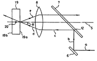
- 광학기구(2)의 광축(5)과 평행하게 발사된 측정광속으로서의 편광 He-Ne레이저광선(a)을 광축에 대해서 45도의 경사각도를 유지하면서 평행이동자재로운 가동미러(6)에서 반사하고, 상기 가동미러에서 반사된 측정광속(c)을 광축과 45도의 경사각도로서 배치된 고정미러에서 반사하고, 상기 고정미러에서 반사된 측정광속을 대물렌즈(8)에서 굴절시키고, 그리고 투명체(19)를 통해서는 불투명체(20)로 향하여 조사하고, 상기 불투명체의 표면에서 반사된 측정광속(m)을 다시 대물렌즈에서 굴절시킨 후 광위치검출기(11)에서 수광하고, 상기 광위치검출기로부터의 위치신호에 대응하는 초점위치맞춤기구(3)에서, 적어도 불투명체와 대물렌즈간의 거리를 조정함으러써 측정광속을 불투명체의 표면으로 자동적으로 초점위치를 맞추는 것으로서, 상기의 가동미러를 불투명체측으로 평행이동시킴으로써 고정미러에서 반사된 측정광속(c)을 대물렌즈의 중심부측에서 굴절시키고, 측정광속을 광축에 접근시킨 좁은 조사각도로써 대물렌즈와 불투명체간에 개재하는 투명체를 통하여 불투명체 조사하는 것을 특징으로 하는 비접촉자동초점위치맞춤방법.
- 상기 투명체가 그 내부에 투명체의 표면 사이즈보다 좁은 표면 사이즈를 가진 불투명체를 포함하고, 그리고 투명체의 표면이외에서 반사되는 측정광속이 불투명체의 표면이외 또는 표면에서 반사되는 측정광속을 포함하는 것인 청구범위 제4항에 있어서의 방법.
- 상기 투명체의 이면측에, 투명체의 표면사이즈 보다 좁은 표면사이즈를 가진 불투명체가 접합 또는 이간배치되고, 상기 투명체의 표면이외에서 반사되는 측정광속이 불투명체의 표면이외 또는 표면에서 반사되는 측정광속을 포함하는 것인 청구범위 제4항에 있어서의 방법.
- 광학기구의 광축과 평행하게 발사된 측정광속으로서의 편광 He-Ne레이저광선을, 광축에 대해서 45도의 경사각도를 유지하면서 평행이동자재로운 가동미러에서 반사하고, 상기 가동미러에서 반사된 측정광속을 광축과 45도의 경사각도로 배치된 고정미러에서 반사하고, 상기 고정미러에서 반사된 측정광속을 대물렌즈에서 굴절시키고 그리고 대상물의 표면에 형성되어 있는 깊은 미소한 지름의 구멍의 밑바닥에 향하여 조사하고, 상기 밑바닥의 표면에서 반사된 측정광속을 다시 대물랜즈에서 굴절시킨 후 광위치검출기에서 수광하고, 상기 광위치검출기로부터의 위치신호에 대응하는 초점위치맞춤기구에서, 적어도 구멍의 밑바닥과 대물렌즈간의 거리를 조정함으로써 측정광속을 밑바닥의 표면으로 자동적으로 초점위치를 맞추는 것으로서, 상기의 가동미러를 대상물측으로 평행이동시킴으로써 고정미러에서 반사된 측정광속을 대물렌즈의 중심부측에서 굴절시키고, 측정광속을 광축으로 접근시킨 좁은 조사각도로써 구멍의 밑바닥에 조사하는 것을 특징으로 하는 비접촉자동초점위치맞춤방법.
- 측정광속으로서의 편광 He-Ne레이저광선(a)을 광학기구의 광축(5)과 평행하게 발사하는 레이저 기구(1)와 ; 광축에 대해서 평행이동이 자재롭고, 또한 상기 레이저기구로 부터 발사된 측정광속을 직각방향으로 반사가 자재로운 가동미러(6)와, 상기 가동미러에서 반사된 측정광속(b)을 광축과 평행한 방향으로 반사하고, 그 측정광속(c)을 가동미러의 평행이동위치에 대응하여 광축으로 접근 및 이탈이 자재로운 측정광속으로하는 고정미러(7)와, 상기 고정미러에서 반사된 측정광속(c)과 광축과의 거리에 따른 조사각도로써 그 측정광속을 대상물(4)에 조사시킴과 동시에 대상물에서 반사된 측정광속을 다시 굴절하는 대물렌즈(8)와, 대상물로부터 반사되어 대물렌즈에서 굴절된 측정광속(f)을 광축상에서 결상시키는 결상렌즈(9) 및 상기 결상렌즈를 통과한 측정광속(g)을 수광하는 광위치검출기(11)로 이루어진 광학기구(2)와 ; 그리고 광위치검출기로부터의 위치신호에 따라 광학기구(2)로부터 조사되는 측정광속을 대상물(4)의 표면으로 자동적으로 초점위치맞춤하여야 할, 적어도 대상물 또는 대물렌즈의 어느 것인가를 이동시켜 대상물과 대물렌즈간의 거리를 조정자재롭게 하는 초점위치 맞춤기구(3)로 구성됨을 특징으로 하는 비접촉자동초점위치맞춤장치.
- 상기 고정미러가 하아프미러인 청구범위 제8항에 있어서의 장치.
- 상기 광위치검출기가 반도체 광위치검출기(POSITION-SENSITIVE DETECTOR)인 청구범위 제8항 또는 제9항에 있어서의 장치.
- 상기 초점위치맞춤기구가 서어보기구를 구비하고 있는 청구범위 제8항 내지 제10항중 어느 하나에 있어서의 장치.
Applications Claiming Priority (3)
| Application Number | Priority Date | Filing Date | Title |
|---|---|---|---|
| JP308,029 | 1986-12-25 | ||
| JP61308029A JPS63163313A (ja) | 1986-12-25 | 1986-12-25 | 非接触自動焦点位置合わせ装置 |
| JP61-308029 | 1986-12-25 |
Publications (2)
| Publication Number | Publication Date |
|---|---|
| KR880008043A KR880008043A (ko) | 1988-08-30 |
| KR940002356B1 true KR940002356B1 (ko) | 1994-03-23 |
Family
ID=17976030
Family Applications (1)
| Application Number | Title | Priority Date | Filing Date |
|---|---|---|---|
| KR1019870014764A KR940002356B1 (ko) | 1986-12-25 | 1987-12-23 | 비접촉자동초점위치맞춤방법 및 장치 |
Country Status (5)
| Country | Link |
|---|---|
| US (1) | US4843228A (ko) |
| EP (1) | EP0273717B1 (ko) |
| JP (1) | JPS63163313A (ko) |
| KR (1) | KR940002356B1 (ko) |
| DE (1) | DE3784231T2 (ko) |
Families Citing this family (17)
| Publication number | Priority date | Publication date | Assignee | Title |
|---|---|---|---|---|
| US5061062A (en) * | 1990-07-02 | 1991-10-29 | General Electric Company | Focus spot size controller for a variable depth range camera |
| DE4131737C2 (de) * | 1991-09-24 | 1997-05-07 | Zeiss Carl Fa | Autofokus-Anordnung für ein Stereomikroskop |
| JPH0812046B2 (ja) * | 1993-05-24 | 1996-02-07 | 三鷹光器株式会社 | 二段検出式非接触位置決め装置 |
| US5912447A (en) * | 1997-01-14 | 1999-06-15 | United Parcel Service Of America, Inc. | Concentric optical path equalizer with radially moving mirrors |
| JP3019835B2 (ja) * | 1998-04-22 | 2000-03-13 | 日本電気株式会社 | 焦点検出装置 |
| EP1031825B1 (en) * | 1999-02-26 | 2006-06-14 | Yokogawa Electric Corporation | Double pass monochromator |
| SE521173C2 (sv) * | 1998-09-17 | 2003-10-07 | Spectra Prec Ab | Elektronisk distansmätanordning |
| US6486457B1 (en) * | 1999-10-07 | 2002-11-26 | Agilent Technologies, Inc. | Apparatus and method for autofocus |
| JP3881498B2 (ja) * | 2000-05-25 | 2007-02-14 | ペンタックス株式会社 | 光波測距儀 |
| AUPR183600A0 (en) * | 2000-12-01 | 2001-01-04 | Sci.com Imaging Australia Pty Ltd | Lens assembly |
| DE10124433A1 (de) * | 2001-05-18 | 2002-11-21 | Bosch Gmbh Robert | Vorrichtung zur optischen Distanzmessung |
| JP3825701B2 (ja) * | 2001-06-07 | 2006-09-27 | ペンタックス株式会社 | 測量機の光軸自動調整装置 |
| JP4121803B2 (ja) * | 2002-08-08 | 2008-07-23 | 株式会社トプコン | 光波距離測定装置 |
| JP2006308709A (ja) * | 2005-04-27 | 2006-11-09 | Tohoku Univ | 顕微鏡ステージ、および、焦点位置計測装置と共焦点顕微鏡システム |
| KR100939679B1 (ko) * | 2007-12-11 | 2010-02-03 | (주)가하 | 자동 초점 조절 장치 및 그 방법 |
| DE102009019290B4 (de) | 2009-04-30 | 2011-09-01 | Ludwig-Maximilian-Universität | Mikroskopvorrichtung |
| JP5400499B2 (ja) * | 2009-06-29 | 2014-01-29 | オリンパス株式会社 | 焦点検出装置 |
Family Cites Families (10)
| Publication number | Priority date | Publication date | Assignee | Title |
|---|---|---|---|---|
| FR2325953A1 (fr) * | 1975-09-29 | 1977-04-22 | Thomson Brandt | Senseur optique de focalisation et dispositif de focalisation comportant un tel senseur |
| JPS5541432A (en) * | 1978-09-20 | 1980-03-24 | Nippon Kogaku Kk <Nikon> | Focus detector |
| US4383168A (en) * | 1980-06-02 | 1983-05-10 | Raytheon Company | Automatic focusing apparatus |
| JPS5752006A (en) * | 1980-08-19 | 1982-03-27 | Olympus Optical Co Ltd | Method and device for detecting focus |
| US4530600A (en) * | 1982-02-22 | 1985-07-23 | Northrop Corporation | Variable attenuator for optical transceiver |
| JPS59109805A (ja) * | 1982-12-16 | 1984-06-25 | Matsushita Electric Ind Co Ltd | 位置検出装置 |
| US4630927A (en) * | 1983-02-15 | 1986-12-23 | General Electric Company | Optical projector |
| US4611912A (en) * | 1983-04-04 | 1986-09-16 | Ball Corporation | Method and apparatus for optically measuring distance and velocity |
| JPS60100114A (ja) * | 1983-11-05 | 1985-06-04 | Canon Inc | 合焦検出装置 |
| JPS62929A (ja) * | 1985-06-27 | 1987-01-06 | Matsushita Electric Ind Co Ltd | カメラの自動焦点調節装置 |
-
1986
- 1986-12-25 JP JP61308029A patent/JPS63163313A/ja active Granted
-
1987
- 1987-12-18 US US07/134,739 patent/US4843228A/en not_active Expired - Lifetime
- 1987-12-23 KR KR1019870014764A patent/KR940002356B1/ko not_active IP Right Cessation
- 1987-12-23 EP EP87311393A patent/EP0273717B1/en not_active Expired - Lifetime
- 1987-12-23 DE DE8787311393T patent/DE3784231T2/de not_active Expired - Fee Related
Also Published As
| Publication number | Publication date |
|---|---|
| JPS63163313A (ja) | 1988-07-06 |
| DE3784231D1 (de) | 1993-03-25 |
| EP0273717B1 (en) | 1993-02-17 |
| KR880008043A (ko) | 1988-08-30 |
| EP0273717A3 (en) | 1988-11-17 |
| US4843228A (en) | 1989-06-27 |
| JPH0563771B2 (ko) | 1993-09-13 |
| DE3784231T2 (de) | 1993-06-03 |
| EP0273717A2 (en) | 1988-07-06 |
Similar Documents
| Publication | Publication Date | Title |
|---|---|---|
| KR940002356B1 (ko) | 비접촉자동초점위치맞춤방법 및 장치 | |
| US6856381B2 (en) | Method for carrying out the non-contact measurement of geometries of objects | |
| JP2913984B2 (ja) | 傾斜角測定装置 | |
| EP0627610B1 (en) | Two-stage detection noncontact positioning apparatus | |
| US5309214A (en) | Method for measuring distributed dispersion of gradient-index optical elements and optical system to be used for carrying out the method | |
| JPH01239404A (ja) | 対象物のエッジ検出方法及びその装置 | |
| KR100878425B1 (ko) | 표면 측정 장치 | |
| JPH11173821A (ja) | 光学式検査装置 | |
| JPH08261734A (ja) | 形状測定装置 | |
| JP3222214B2 (ja) | 対象面の位置検出装置 | |
| JP2005003667A (ja) | 基準軸設定光学系、並びにこれを用いた偏心量測定機及び偏心測定方法 | |
| JPS62502421A (ja) | 二次元の対象物を整向、検査及び/または測定するための装置 | |
| JP6980304B2 (ja) | 非接触内面形状測定装置 | |
| JPH06148029A (ja) | 光ファイバの傾斜角測定方法および光コネクタ | |
| JP3279815B2 (ja) | 変位・傾き検出方法およびそれを用いた自動焦点装置 | |
| JPH0563772B2 (ko) | ||
| JPH06137827A (ja) | 光学的段差測定器 | |
| CN112880585A (zh) | 非接触形状测定装置 | |
| JPH08106040A (ja) | 位置検出装置 | |
| JPH0563773B2 (ko) | ||
| JPS6363907A (ja) | 非接触式高さ測定方法 | |
| JPH0617934B2 (ja) | 非接触自動位置合わせ装置 | |
| JP2989995B2 (ja) | 位置合せ装置 | |
| JPS63199311A (ja) | 二方向非接触自動焦点位置合わせ方法及び装置 | |
| JPH09120940A (ja) | 位置合わせ方法及び位置合わせ装置 |
Legal Events
| Date | Code | Title | Description |
|---|---|---|---|
| PA0109 | Patent application |
Patent event code: PA01091R01D Comment text: Patent Application Patent event date: 19871223 |
|
| PG1501 | Laying open of application | ||
| A201 | Request for examination | ||
| PA0201 | Request for examination |
Patent event code: PA02012R01D Patent event date: 19910523 Comment text: Request for Examination of Application Patent event code: PA02011R01I Patent event date: 19871223 Comment text: Patent Application |
|
| G160 | Decision to publish patent application | ||
| PG1605 | Publication of application before grant of patent |
Comment text: Decision on Publication of Application Patent event code: PG16051S01I Patent event date: 19940228 |
|
| E701 | Decision to grant or registration of patent right | ||
| PE0701 | Decision of registration |
Patent event code: PE07011S01D Comment text: Decision to Grant Registration Patent event date: 19940614 |
|
| GRNT | Written decision to grant | ||
| PR0701 | Registration of establishment |
Comment text: Registration of Establishment Patent event date: 19940722 Patent event code: PR07011E01D |
|
| PR1002 | Payment of registration fee |
Payment date: 19940722 End annual number: 3 Start annual number: 1 |
|
| PR1001 | Payment of annual fee |
Payment date: 19961129 Start annual number: 4 End annual number: 4 |
|
| PR1001 | Payment of annual fee |
Payment date: 19971216 Start annual number: 5 End annual number: 5 |
|
| PR1001 | Payment of annual fee |
Payment date: 19990128 Start annual number: 6 End annual number: 6 |
|
| PR1001 | Payment of annual fee |
Payment date: 20000221 Start annual number: 7 End annual number: 7 |
|
| PR1001 | Payment of annual fee |
Payment date: 20010323 Start annual number: 8 End annual number: 8 |
|
| PR1001 | Payment of annual fee |
Payment date: 20020302 Start annual number: 9 End annual number: 9 |
|
| PR1001 | Payment of annual fee |
Payment date: 20030224 Start annual number: 10 End annual number: 10 |
|
| PR1001 | Payment of annual fee |
Payment date: 20040219 Start annual number: 11 End annual number: 11 |
|
| FPAY | Annual fee payment |
Payment date: 20050224 Year of fee payment: 12 |
|
| PR1001 | Payment of annual fee |
Payment date: 20050224 Start annual number: 12 End annual number: 12 |
|
| LAPS | Lapse due to unpaid annual fee | ||
| PC1903 | Unpaid annual fee |