KR20240035542A - Quenching device and method and manufacturing method of metal plate - Google Patents
Quenching device and method and manufacturing method of metal plate Download PDFInfo
- Publication number
- KR20240035542A KR20240035542A KR1020247004915A KR20247004915A KR20240035542A KR 20240035542 A KR20240035542 A KR 20240035542A KR 1020247004915 A KR1020247004915 A KR 1020247004915A KR 20247004915 A KR20247004915 A KR 20247004915A KR 20240035542 A KR20240035542 A KR 20240035542A
- Authority
- KR
- South Korea
- Prior art keywords
- metal plate
- cooling
- roll
- temperature
- quenching
- Prior art date
Links
- 239000002184 metal Substances 0.000 title claims abstract description 224
- 229910052751 metal Inorganic materials 0.000 title claims abstract description 224
- 238000010791 quenching Methods 0.000 title claims description 45
- 230000000171 quenching effect Effects 0.000 title claims description 44
- 238000000034 method Methods 0.000 title claims description 34
- 238000004519 manufacturing process Methods 0.000 title claims description 18
- 238000001816 cooling Methods 0.000 claims abstract description 145
- 230000000452 restraining effect Effects 0.000 claims abstract description 50
- 239000012809 cooling fluid Substances 0.000 claims description 29
- 229910000831 Steel Inorganic materials 0.000 claims description 27
- 239000010959 steel Substances 0.000 claims description 27
- 230000009466 transformation Effects 0.000 claims description 14
- 229910000734 martensite Inorganic materials 0.000 claims description 11
- 239000010960 cold rolled steel Substances 0.000 claims description 7
- 238000005246 galvanizing Methods 0.000 claims description 4
- 239000007921 spray Substances 0.000 claims description 2
- 230000000052 comparative effect Effects 0.000 description 13
- XLYOFNOQVPJJNP-UHFFFAOYSA-N water Substances O XLYOFNOQVPJJNP-UHFFFAOYSA-N 0.000 description 13
- 238000005452 bending Methods 0.000 description 11
- 238000000137 annealing Methods 0.000 description 7
- 230000008859 change Effects 0.000 description 6
- 238000010586 diagram Methods 0.000 description 6
- 239000007788 liquid Substances 0.000 description 5
- 230000000873 masking effect Effects 0.000 description 4
- 238000005507 spraying Methods 0.000 description 4
- 229910001335 Galvanized steel Inorganic materials 0.000 description 3
- 230000007547 defect Effects 0.000 description 3
- 239000008397 galvanized steel Substances 0.000 description 3
- 230000007246 mechanism Effects 0.000 description 3
- 239000000203 mixture Substances 0.000 description 3
- 230000001629 suppression Effects 0.000 description 3
- 238000009835 boiling Methods 0.000 description 2
- 230000008602 contraction Effects 0.000 description 2
- 230000006378 damage Effects 0.000 description 2
- 238000005516 engineering process Methods 0.000 description 2
- 238000002474 experimental method Methods 0.000 description 2
- 229910052748 manganese Inorganic materials 0.000 description 2
- 239000000463 material Substances 0.000 description 2
- 238000004458 analytical method Methods 0.000 description 1
- 229910052804 chromium Inorganic materials 0.000 description 1
- 239000000110 cooling liquid Substances 0.000 description 1
- 239000000498 cooling water Substances 0.000 description 1
- 229910052802 copper Inorganic materials 0.000 description 1
- 230000000368 destabilizing effect Effects 0.000 description 1
- 230000000694 effects Effects 0.000 description 1
- 230000005484 gravity Effects 0.000 description 1
- 238000010438 heat treatment Methods 0.000 description 1
- 239000012535 impurity Substances 0.000 description 1
- 238000012423 maintenance Methods 0.000 description 1
- 229910052750 molybdenum Inorganic materials 0.000 description 1
- 229910052759 nickel Inorganic materials 0.000 description 1
- 229910052758 niobium Inorganic materials 0.000 description 1
- 230000008569 process Effects 0.000 description 1
- 230000004044 response Effects 0.000 description 1
- 230000004043 responsiveness Effects 0.000 description 1
- 238000005096 rolling process Methods 0.000 description 1
- 238000004381 surface treatment Methods 0.000 description 1
- 229910052719 titanium Inorganic materials 0.000 description 1
- 229910052720 vanadium Inorganic materials 0.000 description 1
Images


Classifications
-
- C—CHEMISTRY; METALLURGY
- C21—METALLURGY OF IRON
- C21D—MODIFYING THE PHYSICAL STRUCTURE OF FERROUS METALS; GENERAL DEVICES FOR HEAT TREATMENT OF FERROUS OR NON-FERROUS METALS OR ALLOYS; MAKING METAL MALLEABLE, e.g. BY DECARBURISATION OR TEMPERING
- C21D9/00—Heat treatment, e.g. annealing, hardening, quenching or tempering, adapted for particular articles; Furnaces therefor
- C21D9/52—Heat treatment, e.g. annealing, hardening, quenching or tempering, adapted for particular articles; Furnaces therefor for wires; for strips ; for rods of unlimited length
- C21D9/54—Furnaces for treating strips or wire
- C21D9/56—Continuous furnaces for strip or wire
- C21D9/573—Continuous furnaces for strip or wire with cooling
-
- B—PERFORMING OPERATIONS; TRANSPORTING
- B21—MECHANICAL METAL-WORKING WITHOUT ESSENTIALLY REMOVING MATERIAL; PUNCHING METAL
- B21B—ROLLING OF METAL
- B21B45/00—Devices for surface or other treatment of work, specially combined with or arranged in, or specially adapted for use in connection with, metal-rolling mills
- B21B45/02—Devices for surface or other treatment of work, specially combined with or arranged in, or specially adapted for use in connection with, metal-rolling mills for lubricating, cooling, or cleaning
-
- C—CHEMISTRY; METALLURGY
- C21—METALLURGY OF IRON
- C21D—MODIFYING THE PHYSICAL STRUCTURE OF FERROUS METALS; GENERAL DEVICES FOR HEAT TREATMENT OF FERROUS OR NON-FERROUS METALS OR ALLOYS; MAKING METAL MALLEABLE, e.g. BY DECARBURISATION OR TEMPERING
- C21D1/00—General methods or devices for heat treatment, e.g. annealing, hardening, quenching or tempering
- C21D1/18—Hardening; Quenching with or without subsequent tempering
-
- C—CHEMISTRY; METALLURGY
- C21—METALLURGY OF IRON
- C21D—MODIFYING THE PHYSICAL STRUCTURE OF FERROUS METALS; GENERAL DEVICES FOR HEAT TREATMENT OF FERROUS OR NON-FERROUS METALS OR ALLOYS; MAKING METAL MALLEABLE, e.g. BY DECARBURISATION OR TEMPERING
- C21D1/00—General methods or devices for heat treatment, e.g. annealing, hardening, quenching or tempering
- C21D1/56—General methods or devices for heat treatment, e.g. annealing, hardening, quenching or tempering characterised by the quenching agents
- C21D1/60—Aqueous agents
-
- C—CHEMISTRY; METALLURGY
- C21—METALLURGY OF IRON
- C21D—MODIFYING THE PHYSICAL STRUCTURE OF FERROUS METALS; GENERAL DEVICES FOR HEAT TREATMENT OF FERROUS OR NON-FERROUS METALS OR ALLOYS; MAKING METAL MALLEABLE, e.g. BY DECARBURISATION OR TEMPERING
- C21D1/00—General methods or devices for heat treatment, e.g. annealing, hardening, quenching or tempering
- C21D1/62—Quenching devices
- C21D1/63—Quenching devices for bath quenching
-
- C—CHEMISTRY; METALLURGY
- C21—METALLURGY OF IRON
- C21D—MODIFYING THE PHYSICAL STRUCTURE OF FERROUS METALS; GENERAL DEVICES FOR HEAT TREATMENT OF FERROUS OR NON-FERROUS METALS OR ALLOYS; MAKING METAL MALLEABLE, e.g. BY DECARBURISATION OR TEMPERING
- C21D1/00—General methods or devices for heat treatment, e.g. annealing, hardening, quenching or tempering
- C21D1/62—Quenching devices
- C21D1/667—Quenching devices for spray quenching
-
- C—CHEMISTRY; METALLURGY
- C21—METALLURGY OF IRON
- C21D—MODIFYING THE PHYSICAL STRUCTURE OF FERROUS METALS; GENERAL DEVICES FOR HEAT TREATMENT OF FERROUS OR NON-FERROUS METALS OR ALLOYS; MAKING METAL MALLEABLE, e.g. BY DECARBURISATION OR TEMPERING
- C21D8/00—Modifying the physical properties by deformation combined with, or followed by, heat treatment
- C21D8/02—Modifying the physical properties by deformation combined with, or followed by, heat treatment during manufacturing of plates or strips
- C21D8/0205—Modifying the physical properties by deformation combined with, or followed by, heat treatment during manufacturing of plates or strips of ferrous alloys
-
- C—CHEMISTRY; METALLURGY
- C21—METALLURGY OF IRON
- C21D—MODIFYING THE PHYSICAL STRUCTURE OF FERROUS METALS; GENERAL DEVICES FOR HEAT TREATMENT OF FERROUS OR NON-FERROUS METALS OR ALLOYS; MAKING METAL MALLEABLE, e.g. BY DECARBURISATION OR TEMPERING
- C21D9/00—Heat treatment, e.g. annealing, hardening, quenching or tempering, adapted for particular articles; Furnaces therefor
- C21D9/46—Heat treatment, e.g. annealing, hardening, quenching or tempering, adapted for particular articles; Furnaces therefor for sheet metals
-
- C—CHEMISTRY; METALLURGY
- C22—METALLURGY; FERROUS OR NON-FERROUS ALLOYS; TREATMENT OF ALLOYS OR NON-FERROUS METALS
- C22C—ALLOYS
- C22C38/00—Ferrous alloys, e.g. steel alloys
- C22C38/02—Ferrous alloys, e.g. steel alloys containing silicon
-
- C—CHEMISTRY; METALLURGY
- C22—METALLURGY; FERROUS OR NON-FERROUS ALLOYS; TREATMENT OF ALLOYS OR NON-FERROUS METALS
- C22C—ALLOYS
- C22C38/00—Ferrous alloys, e.g. steel alloys
- C22C38/04—Ferrous alloys, e.g. steel alloys containing manganese
-
- C—CHEMISTRY; METALLURGY
- C21—METALLURGY OF IRON
- C21D—MODIFYING THE PHYSICAL STRUCTURE OF FERROUS METALS; GENERAL DEVICES FOR HEAT TREATMENT OF FERROUS OR NON-FERROUS METALS OR ALLOYS; MAKING METAL MALLEABLE, e.g. BY DECARBURISATION OR TEMPERING
- C21D2211/00—Microstructure comprising significant phases
- C21D2211/008—Martensite
-
- C—CHEMISTRY; METALLURGY
- C22—METALLURGY; FERROUS OR NON-FERROUS ALLOYS; TREATMENT OF ALLOYS OR NON-FERROUS METALS
- C22C—ALLOYS
- C22C38/00—Ferrous alloys, e.g. steel alloys
-
- C—CHEMISTRY; METALLURGY
- C22—METALLURGY; FERROUS OR NON-FERROUS ALLOYS; TREATMENT OF ALLOYS OR NON-FERROUS METALS
- C22C—ALLOYS
- C22C38/00—Ferrous alloys, e.g. steel alloys
- C22C38/60—Ferrous alloys, e.g. steel alloys containing lead, selenium, tellurium, or antimony, or more than 0.04% by weight of sulfur
Landscapes
- Chemical & Material Sciences (AREA)
- Engineering & Computer Science (AREA)
- Mechanical Engineering (AREA)
- Materials Engineering (AREA)
- Metallurgy (AREA)
- Organic Chemistry (AREA)
- Physics & Mathematics (AREA)
- Thermal Sciences (AREA)
- Crystallography & Structural Chemistry (AREA)
- Heat Treatment Of Strip Materials And Filament Materials (AREA)
Abstract
??칭시에 발생하는 금속판의 형상의 편차를 억제한다.
금속판의 ??칭 장치 (1) 는, 금속판을 반송하면서 냉각하는 것으로, 반송하는 금속판 (S) 을 냉각하는 냉각 장치 (10) 와, 냉각 장치 (10) 에 의해 냉각된 금속판 (S) 을 두께 방향으로 구속하면서 반송하는 구속 롤 (20) 과, 구속 롤 (20) 을 금속판 (S) 의 반송 방향을 따라서 이동시키는 롤 이동 장치 (30) 와, 롤 이동 장치 (30) 의 동작을 제어하여 구속 롤 (20) 의 위치를 조정하는 이동 제어 장치 (40) 를 구비한다.Suppresses deviations in the shape of the metal plate that occur during stamping.
The metal plate cooling device 1 cools the metal plate while conveying it, and includes a cooling device 10 that cools the conveyed metal plate S, and a thickness of the metal plate S cooled by the cooling device 10. A restraining roll 20 that conveys while restraining in a certain direction, a roll moving device 30 that moves the restraining roll 20 along the conveying direction of the metal plate S, and restraint by controlling the operation of the roll moving device 30. A movement control device 40 is provided to adjust the position of the roll 20.
Description
본 발명은, 금속판을 연속적으로 반송하면서 어닐링을 실시하는 ??칭 장치 및 ??칭 방법 그리고 금속판의 제조 방법에 관한 것이다.The present invention relates to a quenching device and quenching method for performing annealing while continuously transporting a metal plate, and a method for manufacturing a metal plate.
금속판을 연속적으로 반송하면서 어닐링을 실시하는 연속 어닐링 설비에 있어서, 금속판이 가열 후에 냉각되어 상 변태를 일으키는 것에 의해, 금속판 조직의 만들어 넣기가 행해진다. 특히, 자동차 업계에서는 차체의 경량화와 충돌 안전성의 양립을 목적으로 하여, 박육화한 고장력 강판 (하이텐) 의 수요가 증가하고 있다. 고장력 강판의 제조시에는, 강판을 급속히 냉각시키는 기술이 중요해진다. 금속판의 냉각 속도가 가장 빠른 기술의 하나로서, 워터 ??칭법이 알려져 있다. 워터 ??칭법에서는, 가열된 금속판이 수중에 침지됨과 동시에, 수중 내에 설치된 ??치 노즐에 의해 냉각수가 금속판에 분사됨으로써, 금속판의 ??칭이 행해진다.In a continuous annealing facility in which annealing is performed while continuously conveying a metal plate, the metal plate is cooled after heating to cause a phase transformation, thereby creating a metal plate structure. In particular, in the automobile industry, demand for thinner high-strength steel sheets (HI-TEN) is increasing for the purpose of reducing the weight of the car body and achieving both crash safety. When manufacturing high-strength steel sheets, technology for rapidly cooling the steel sheets becomes important. As one of the technologies with the fastest cooling rate of metal plates, the water cooling method is known. In the water quenching method, quenching of the metal plate is performed by immersing the heated metal plate in water and simultaneously spraying cooling water onto the metal plate through a quench nozzle installed in the water.
금속판의 ??칭시에는, 금속판에 휨이나 파상 변형 등의 형상 불량이 발생한다. 이것은, 급랭되는 것에 의한 금속판의 열 수축 등에서 기인한다. 특히, 금속판의 온도가, 마텐자이트 변태가 개시되는 온도 Ms 로부터 마텐자이트 변태가 종료되는 온도 Mf 가 되었을 때에, 급격한 열 수축과 변태 팽창이 동시에 발생한다.When forming a metal plate, shape defects such as bending or waviness deformation occur in the metal plate. This is due to thermal shrinkage of the metal plate due to rapid cooling. In particular, when the temperature of the metal plate goes from the temperature Ms at which martensite transformation begins to the temperature Mf at which martensite transformation ends, rapid thermal contraction and transformation expansion occur simultaneously.
그래서, 종래부터 ??칭시에 있어서의 금속판의 형상 불량을 방지하기 위해 여러 가지 수법이 제안되어 있다 (예를 들면 특허문헌 1, 2 참조). 특허문헌 1 에는, 금속판의 마텐자이트 변태가 개시되는 Ms 점의 온도를 TMs (℃), 마텐자이트 변태가 종료되는 Mf 점의 온도를 TMf (℃) 로 했을 때, 금속판의 온도가 (TMs+150) (℃) 에서 (TMf-150) (℃) 범위에 있어서, 냉각 액체 중에 형성된 한 쌍의 구속 롤에 의해 금속판을 구속하는 수법이 제안되어 있다.Therefore, various methods have conventionally been proposed to prevent shape defects in metal plates during forming (for example, see Patent Documents 1 and 2). In Patent Document 1, when the temperature at the Ms point where the martensite transformation of the metal sheet starts is TMs (°C) and the temperature at the Mf point where the martensite transformation ends is TMf (°C), the temperature of the metal sheet is (TMs+150 ) (°C) to (TMf-150) (°C) range, a method of restraining a metal plate with a pair of restraint rolls formed in a cooling liquid has been proposed.
특허문헌 2 에는, 금속판의 표면에 복수의 물 분출 노즐로부터 물을 분사함으로써 냉각하는 ??칭 방법을 실시할 때에, 구속 롤에 의해 금속판을 구속하면서, 가동 마스킹에 의해 냉각 유체에 의한 금속판의 냉각 개시 위치와 구속 롤의 거리를 제어하는 것이 개시되어 있다. 또한, 특허문헌 1 과 동일하게, 금속판의 마텐자이트 변태가 개시되는 Ms 점의 온도를 TMs (℃), 마텐자이트 변태가 종료되는 Mf 점의 온도를 TMf (℃) 로 했을 때, 금속판을 (TMs+150) (℃) ∼ (TMf-150) (℃) 의 온도에서 구속 롤을 통과시키는 수법이 제안되어 있다.In
그러나, 특허문헌 1 에 기재된 방법에서는, 금속판의 제조 조건에 따라, 금속판의 온도가 (TMs+150) (℃) ∼ (TMf-150) (℃) 의 범위가 되는 위치가 변화한다. 이 때문에, 금속판의 온도가 (TMs+150) (℃) ∼ (TMf-150) (℃) 가 되는 위치에서 구속 롤이 금속판을 구속할 수 없어, 금속판의 형상에 편차가 발생할 가능성이 있다.However, in the method described in Patent Document 1, the position where the temperature of the metal plate is in the range of (TMs+150) (°C) to (TMf-150) (°C) changes depending on the manufacturing conditions of the metal plate. For this reason, the restraining roll cannot restrain the metal plate at a position where the temperature of the metal plate is (TMs+150) (°C) to (TMf-150) (°C), and there is a possibility that deviation in the shape of the metal plate occurs.
특허문헌 2 에 기재된 방법에서는, 가동 마스킹에 충돌한 물이 중력에 의해 낙하되어, 가동 마스킹의 하부의 물 분출 노즐로부터 분사된 물에 간섭함으로써, 금속판의 냉각 능력이 불안정해진다. 또한, 노즐마다 마스킹되기 때문에, 냉각 능력이 단계적으로 (비연속적으로) 변하고, 그 결과, 금속판의 온도가 (TMs+150) (℃) ∼ (TMf-150) (℃) 가 되는 위치가 불안정해져, 금속판의 형상에 편차가 발생할 가능성이 있다.In the method described in
본 발명은 이와 같은 과제를 해결하기 위해 이루어진 것으로, 금속판을 구속하는 위치에서의 금속판의 온도를 고정밀도로 제어하여, ??칭시에 발생하는 금속판의 형상의 편차를 억제할 수 있는 ??칭 장치 및 ??칭 방법 그리고 금속판 제품의 제조 방법을 제공하는 것을 목적으로 한다.The present invention was made to solve such problems, and includes a quenching device capable of controlling the temperature of a metal plate at a position where the metal plate is restrained with high precision and suppressing deviation in the shape of the metal plate that occurs during quenching. The purpose is to provide a quenching method and a manufacturing method of metal plate products.
[1] 금속판을 반송하면서 냉각하는 금속판의 ??칭 장치로서, 반송하는 상기 금속판을 냉각하는 냉각 장치와, 상기 냉각 장치에 의해 냉각된 상기 금속판을 두께 방향으로 구속하면서 반송하는 구속 롤과, 상기 구속 롤을 상기 금속판의 반송 방향을 따라 이동시키는 롤 이동 장치와, 상기 롤 이동 장치의 동작을 제어하여 상기 구속 롤의 위치를 조정하는 이동 제어 장치를 구비하는 금속판의 ??칭 장치.[1] A metal plate cooling device that cools a metal plate while conveying it, comprising: a cooling device that cools the conveyed metal plate; a restraining roll that conveys the metal plate cooled by the cooling device while restraining it in the thickness direction; A metal plate quenching device comprising a roll moving device that moves a restraining roll along a conveyance direction of the metal plate, and a movement control device that controls the operation of the roll moving device to adjust the position of the restraining roll.
[2] 상기 냉각 장치는, 상기 금속판에 냉각 유체를 분사하여 냉각하는 복수의 노즐을 갖는 [1] 에 기재된 금속판의 ??칭 장치.[2] The cooling device for a metal plate according to [1], wherein the cooling device has a plurality of nozzles for cooling the metal plate by spraying a cooling fluid.
[3] 상기 냉각 장치는, 상기 금속판을 침지시켜 냉각하는 냉각조를 갖는 [1] 또는 [2] 에 기재된 금속판의 ??칭 장치.[3] The cooling device for a metal plate according to [1] or [2], wherein the cooling device has a cooling tank in which the metal plate is immersed and cooled.
[4] 상기 이동 제어 장치는, 상기 롤 이동 장치의 동작을 제어하여, 상기 금속판이 목표 온도로 되는 위치에서 상기 구속 롤이 상기 금속판을 구속하도록, 상기 구속 롤을 위치 결정하는 [1] ∼ [3] 중 어느 하나에 기재된 금속판의 ??칭 장치.[4] The movement control device controls the operation of the roll movement device to position the restraint roll so that the restraint roll restrains the metal plate at a position where the metal plate reaches the target temperature. [1] to [ 3] The metal plate quenching device according to any one of the above.
[5] 상기 목표 온도는, 상기 금속판의 마텐자이트 변태가 개시되는 Ms 점의 온도를 TMs (℃), 마텐자이트 변태가 종료되는 Mf 점의 온도를 TMf (℃) 로 했을 때, (TMs+150) (℃) ∼ (TMf-150) (℃) 의 온도 범위로 설정되는 [4] 에 기재된 금속판의 ??칭 장치.[5] The above target temperature is (TMs+150 ) The quenching device for the metal plate described in [4], which is set to a temperature range of (℃) to (TMf-150) (℃).
[6] 상기 이동 제어 장치는, 상기 냉각 장치에 의한 냉각 개시 위치로부터 상기 구속 롤까지의 거리를, 상기 금속판의 반송 속도와, 상기 냉각 장치에 의한 냉각 개시시의 상기 금속판의 냉각 개시 온도와, 상기 목표 온도와, 상기 금속판의 냉각 속도에 기초하여 설정하고, 설정한 거리가 되도록 상기 구속 롤의 위치를 이동시키는 [4] 또는 [5] 에 기재된 금속판의 ??칭 장치.[6] The movement control device determines the distance from the cooling start position by the cooling device to the constraint roll, a conveyance speed of the metal plate, a cooling start temperature of the metal plate at the start of cooling by the cooling device, and The metal sheet quenching device according to [4] or [5], wherein the target temperature is set based on the cooling rate of the metal sheet, and the position of the constraint roll is moved to a set distance.
[7] 상기 이동 제어 장치는, 상기 금속판의 반송 속도를 v (mm/s), 냉각 개시 온도를 T1 (℃), 상기 목표 온도를 T2 (℃), 상기 냉각 장치에 의한 상기 금속판의 냉각 속도를 CV (℃/s) 로 했을 때, 상기 냉각 개시 위치로부터 상기 구속 롤까지의 거리 d (mm) 를 식 (1) 에서 구하는 [6] 에 기재된 금속판의 ??칭 장치.[7] The movement control device sets the conveyance speed of the metal plate to v (mm/s), the cooling start temperature to T1 (°C), the target temperature to T2 (°C), and the cooling rate of the metal plate by the cooling device. When CV (°C/s), the distance d (mm) from the cooling start position to the constraint roll is obtained from equation (1). The metal plate quenching device described in [6].
d = (T1-T2)×v/CV (1)d = (T1-T2)×v/CV (One)
[8] 상기 이동 제어 장치에는, 상기 냉각 속도 CV 가 상기 금속판의 냉각 조건을 나타내는 계수 α 와 상기 금속판의 판두께 t 에 의해, CV = α/t 로서 설정되어 있는 [7] 에 기재된 금속판의 ??칭 장치.[8] In the movement control device, the cooling rate CV of the metal plate described in [7] is set as CV = α/t by the coefficient α representing the cooling condition of the metal plate and the plate thickness t of the metal plate. Qing device.
[9] 금속판을 반송하면서 냉각하는 금속판의 ??칭 방법으로서, 냉각한 상기 금속판을 구속 롤에 의해 두께 방향으로 구속할 때, 상기 금속판이 목표 온도로 되어 있는 위치에서 상기 금속판을 구속하도록, 상기 구속 롤을 반송 방향을 따라 이동시키는 금속판의 ??칭 방법.[9] A method of cooling a metal plate while transporting the metal plate, wherein, when the cooled metal plate is restrained in the thickness direction by a restraining roll, the metal plate is restrained at a position where the metal plate is at the target temperature. A method of quenching metal plates by moving restraint rolls along the conveying direction.
[10] 상기 목표 온도는, 상기 금속판의 마텐자이트 변태가 개시되는 Ms 점의 온도를 TMs (℃), 마텐자이트 변태가 종료되는 Mf 점의 온도를 TMf (℃) 로 했을 때, (TMs+150) (℃) ∼ (TMf-150) (℃) 의 온도 범위로 설정되는 [9] 에 기재된 금속판의 ??칭 방법.[10] The above target temperature is (TMs+150 ) The quenching method of a metal plate described in [9], which is set to a temperature range of (℃) to (TMf-150) (℃).
[11] 상기 구속 롤의 이동은, 상기 금속판의 반송 속도와, 냉각 개시시의 상기 금속판의 냉각 개시 온도와, 상기 목표 온도와, 상기 금속판의 냉각 속도에 기초하여, 냉각 개시 위치로부터 상기 구속 롤까지의 거리를 설정하고, 설정한 거리가 되도록 상기 구속 롤을 이동시킴으로써 실시하는 [9] 또는 [10] 에 기재된 금속판의 ??칭 방법.[11] The movement of the restraint roll is based on the conveyance speed of the metal plate, the cooling start temperature of the metal plate at the start of cooling, the target temperature, and the cooling rate of the metal plate, from the cooling start position. The quenching method of a metal plate according to [9] or [10], which is performed by setting a distance to and moving the constraint roll so that it becomes the set distance.
[12] 상기 냉각 개시 위치로부터 상기 구속 롤까지의 거리는, 상기 금속판의 반송 속도를 v (mm/s), 냉각 개시 온도를 T1 (℃), 상기 목표 온도를 T2 (℃), 상기 금속판의 냉각 속도를 CV (℃/s) 로 했을 때, 상기 냉각 개시 위치로부터 상기 구속 롤까지의 거리 d (mm) 를 식 (1) 에서 구하는 [11] 에 기재된 금속판의 ??칭 방법.[12] The distance from the cooling start position to the constraint roll is the conveyance speed of the metal plate in v (mm/s), the cooling start temperature in T1 (°C), the target temperature in T2 (°C), and the cooling of the metal plate. The quenching method of a metal plate described in [11], where the distance d (mm) from the cooling start position to the restraining roll is obtained from equation (1) when the speed is set to CV (°C/s).
d = (T1-T2)×v/CV (1)d = (T1-T2)×v/CV (One)
[13] 상기 냉각 속도 CV 는, 상기 금속판의 냉각 조건을 나타내는 계수 α 와 상기 금속판의 판두께 t 에 의해, CV = α/t 로서 설정되어 있는 [12] 에 기재된 금속판의 ??칭 방법.[13] The cooling method of a metal plate according to [12], wherein the cooling rate CV is set as CV = α/t by a coefficient α representing the cooling condition of the metal plate and the plate thickness t of the metal plate.
[14] [9] ∼ [13] 중 어느 하나에 기재된 금속판의 ??칭 방법을 이용하는, 고강도 냉연 강판의 제조 방법.[14] A method of manufacturing a high-strength cold-rolled steel sheet using the metal sheet quenching method according to any one of [9] to [13].
[15] [14] 에 기재된 방법으로 얻어진 고강도 강판에, 용융 아연 도금 처리, 전기 아연 도금 처리, 혹은 합금화 용융 아연 도금 처리 중 어느 것을 실시하는 고강도 강판의 제조 방법.[15] A method of producing a high-strength steel sheet, in which the high-strength steel sheet obtained by the method described in [14] is subjected to any of hot-dip galvanizing treatment, electrogalvanizing treatment, or alloyed hot-dip galvanizing treatment.
본 발명에 의하면, 금속판의 ??칭시에, 금속판의 온도에 맞춰 구속 롤의 위치를 금속판의 반송 방향을 따라서 조정함으로써, 냉각 개시 위치로부터 구속 롤까지의 거리를 제어하여, ??칭시에 발생하는 금속판의 형상의 편차를 억제할 수 있다.According to the present invention, when cooling a metal plate, the position of the restraining roll is adjusted along the conveyance direction of the metal plate according to the temperature of the metal plate, thereby controlling the distance from the cooling start position to the restraining roll, thereby reducing the Deviation in the shape of the metal plate can be suppressed.
도 1 은, 본 발명의 실시형태에 관련된 ??칭 장치를 나타내는 모식도이다.
도 2 는, 금속판의 휨량의 정의의 일례를 나타내는 모식도이다.
도 3 은, 본 발명예에 있어서의 반송 속도와 목표 온도의 관계를 나타내는 그래프이다.
도 4 는, 본 발명예에 있어서의 반송 속도와 금속판의 휨량의 관계를 나타내는 그래프이다.
도 5 는, 비교예 1 에 있어서의 반송 속도와 목표 온도의 관계를 나타내는 그래프이다.
도 6 은, 비교예 1 에 있어서의 반송 속도와 금속판의 휨량의 관계를 나타내는 그래프이다.
도 7 은, 비교예 2 에 있어서의 반송 속도와 목표 온도의 관계를 나타내는 그래프이다.
도 8 은, 비교예 2 에 있어서의 반송 속도와 금속판의 휨량의 관계를 나타내는 그래프이다.
도 9 는, 본 발명의 실시형태에 관련된 ??칭 장치의 다른 예에 있어서의 구속 롤 및 노즐의 이동을 설명하는 도면이다.1 is a schematic diagram showing a quenching device according to an embodiment of the present invention.
Figure 2 is a schematic diagram showing an example of the definition of the amount of bending of a metal plate.
Fig. 3 is a graph showing the relationship between the conveyance speed and target temperature in the example of the present invention.
Fig. 4 is a graph showing the relationship between the conveyance speed and the amount of bending of the metal plate in the example of the present invention.
Fig. 5 is a graph showing the relationship between the conveyance speed and target temperature in Comparative Example 1.
Figure 6 is a graph showing the relationship between the conveyance speed and the amount of bending of the metal plate in Comparative Example 1.
Fig. 7 is a graph showing the relationship between the conveyance speed and target temperature in Comparative Example 2.
Fig. 8 is a graph showing the relationship between the conveyance speed and the amount of bending of the metal plate in Comparative Example 2.
Fig. 9 is a diagram explaining the movement of the constraint roll and nozzle in another example of the quenching device according to the embodiment of the present invention.
본 발명의 실시형태를 도면에 기초하여 설명한다. 도 1 은, 본 발명의 실시형태에 관련된 ??칭 장치를 나타내는 모식도이다. 또한, 도 1 의 ??칭 장치 (1) 는, 예를 들어 금속판 (S) 으로서 강재의 ??칭을 실시하는 것으로, 연속 어닐링로의 균열대의 출측에 형성된 냉각 설비에 적용된다. 도 1 의 금속판 (S) 의 ??칭 장치 (1) 는, 금속판 (S) 을 냉각하는 냉각 장치 (10) 와, 냉각된 금속판 (S) 을 두께 방향으로 구속하는 구속 롤 (20) 을 구비한다.Embodiments of the present invention will be described based on the drawings. 1 is a schematic diagram showing a quenching device according to an embodiment of the present invention. In addition, the quenching device 1 in FIG. 1 quenches a steel material, for example, a metal plate S, and is applied to a cooling facility formed on the exit side of the crack zone of a continuous annealing furnace. The quenching device 1 for the metal plate S in FIG. 1 includes a
냉각 장치 (10) 는, 냉각 유체 (CF) 를 사용하여 금속판 (S) 을 냉각하는 것으로, 냉각 유체 (CF) 를 저류하는 냉각조 (11) 와, 냉각조 (11) 내에 설치되어, 금속판 (S) 의 표면에 냉각 유체 (CF) 를 분사하는 복수의 노즐 (12) 을 구비한다. 냉각조 (11) 에는 냉각 유체 (CF) 로서 물이 저류되어 있고, 예를 들면 냉각조 (11) 의 상면으로부터 금속판 (S) 이 반송 방향 (BD) 을 향해 침지되어 간다. 또한, 냉각조 (11) 내에는, 금속판 (S) 의 반송 방향을 변경하는 싱크 롤 (2) 이 설치되어 있다.The
복수의 노즐 (12) 은, 예를 들어 ??치 노즐 등으로 이루어지고, 금속판 (S) 의 양면측의 각각에 금속판 (S) 의 반송 방향을 따라서 설치되어 있다. 따라서, 금속판 (S) 은, 냉각조 (11) 내의 냉각 유체 (CF) 및 복수의 노즐 (12) 로부터 분사되는 냉각 유체 (CF) 에 의해 냉각된다. 이와 같이, 냉각조 (11) 와 복수의 노즐 (12) 의 쌍방을 사용하여 금속판 (S) 을 냉각함으로써, 금속판 (S) 의 표면의 비등 상태를 안정시켜, 균일한 형상 제어를 실시할 수 있다.The plurality of
또한, 냉각 유체 (CF) 로서 물을 사용한 워터 ??칭의 경우에 대해 예시하고 있지만, 냉각 유체 (CF) 로서 오일을 사용한 유랭이어도 된다. 또한, 도 1 에 있어서, 복수의 노즐 (12) 이 냉각조 (11) 내에 설치되어 있는 경우에 대해 예시하고 있지만, 금속판 (S) 을 원하는 온도 범위에서 냉각할 수 있는 수법이면, 냉각 방법은 이것에 한정되지 않는다. 예를 들어, 금속판 (S) 을 냉각조 (11) 만으로 냉각해도 되고, 복수의 노즐 (12) 만으로 냉각하도록 해도 된다.In addition, although the case of water cooling using water as the cooling fluid (CF) is illustrated, oil cooling using oil as the cooling fluid (CF) may also be used. In addition, in FIG. 1, the case where a plurality of
냉각조 (11) 내에 노즐 (12) 을 설치하는 경우, 액체 ??칭에 의한 급속 냉각에 있어서 금속판 (S) 과 노즐 (12) 사이의 거리는 중요하다. 비등 현상에 의해 발생하는 증기막을 액체 분류에 의해 파괴함으로써 급속 냉각을 실시하기 때문에, 노즐 (12) 은 금속판 (S) 에 근접하여 설치하는 것이 바람직하다. 노즐 (12) 의 선단부와 금속판 (S) 사이의 거리는, 바람직하게는 10 mm 이상 150 mm 이내이다. 10 mm 미만인 경우, 변형되어 펄럭이는 금속판 (S) 과 노즐 (12) 이 접촉할 가능성이 있다. 또한 150 mm 를 초과하는 경우, 증기막의 파괴 효과가 약해져, 충분한 냉각 능력을 확보하는 것이 곤란해질 가능성이 있다.When installing the
구속 롤 (20) 은, 냉각 장치 (10) 에 의해 냉각된 금속판 (S) 을 두께 방향으로 구속하는 것으로서, 냉각조 (11) 내의 금속판 (S) 의 양면에 각각 설치되어 있다. 또한, 도 1 에 있어서는, 한 쌍의 구속 롤 (20) 이 대향하도록 설치되어 있지만, 구속하는 것이라면 반송 방향을 따라 어긋난 위치에 설치되어 있어도 된다. 또한, 도 1 에서는 한 쌍의 구속 롤 (20) 이 설치되어 있는 경우에 대해 예시하고 있지만, 반송 방향을 따라서 복수의 한 쌍의 구속 롤 (20) 이 설치되어 있어도 된다.The restraining rolls 20 restrain the metal plate S cooled by the cooling
또한, 구속 롤 (20) 의 롤 직경은 롤 강성과 구속 응력에 수반되는 휨과의 상관으로부터, 바람직하게는 50 mm 이상 300 mm 이내이다. 구속 롤 (20) 의 재질은 한정되지 않는다. 구속 롤 (20) 로서 일반적인 강 (鋼) 롤을 사용한 경우로서, 롤 직경이 50 mm 미만인 경우에는, 롤 강성이 부족하여, 휨에 의해 금속판 (S) 에 대해 균일한 구속력을 작용시키는 것이 곤란해져, 파손의 가능성이 있다. 또한, 롤 직경이 300 mm 보다 큰 경우에는, 노즐 (12) 로부터의 분류가 금속판 (S) 에 도달하지 않는 구간이 길어져, 증기막의 파괴가 불충분해지고, 냉각 능력이 저하될 가능성이 있다.In addition, the roll diameter of the constraining
구속 롤 (20) 은, 금속판 (S) 의 반송 방향을 따라, 이동 가능하게 설치되어 있다. 여기서, 반송 방향이란 금속판 (S) 이 반송되는 방향을 가리킨다. 구체적으로는, 금속판 (S) 의 ??칭 장치 (1) 는, 구속 롤 (20) 을 이동시키는 롤 이동 장치 (30) 와, 구속 롤 (20) 의 이동을 제어하는 이동 제어 장치 (40) 를 구비한다. 롤 이동 장치 (30) 는, 예를 들어 모터 등의 공지된 구동 수단을 구비하고 있고, 금속판 (S) 의 반송 방향을 따라서, 구속 롤 (20) 을 금속판 (S) 의 반송 방향 (BD), 혹은 반송 방향 (BD) 과는 반대 방향으로 이동시키도록 구성되어 있다. 구체적으로는, 롤 이동 장치 (30) 는 파워 잭, 나사 기구나 기어 기구에 의한 스크류식 승강 장치, 또한 롤링을 이용하는 저항이 적은 Linear Motion Guide (LM 가이드) 등의 기계 부품을 조합함으로써 적절하게 제작할 수 있다. 도 1 에는, 스크류식 승강 장치에 의해 롤 이동 장치 (30) 를 구성한 예를 나타내고 있다. L 자 형상의 아암 (31) 의 일방의 단부에 구속 롤 (20) 이 회전 가능하게 장착되어 있다. 아암 (31) 의 타방의 단부측에 나사부 (32) 와, 나사부 (32) 에 맞물리는 다른 나사부와, 다른 나사부를 구동하는 구동 수단 (각각 도시 생략) 이 형성되어 있다. 구동 수단은 고정부 (도시 생략) 에 고정되어 있다. 따라서, 구동 수단에서 발생시킨 토크를 받아 다른 나사부가 회전하면, 그에 수반하여 반송 방향 (BD) 과 서로 평행한 방향으로 아암 (31) 이 이동한다.The
상기 서술한 구동 수단이 액체에 침지되면, 당해 구동 수단의 메인터넌스가 곤란해질 가능성이 있다. 그 때문에, 구동 수단은, 냉각조 (11) 의 액면보다 상방에 설치되는 것이 바람직하다. 또한, 구동 수단은, 고온이 되는 노내로부터 차폐된 공간에 설치되는 것이 바람직하다.If the above-described drive means is immersed in liquid, maintenance of the drive means may become difficult. Therefore, the drive means is preferably installed above the liquid level of the
롤 이동 장치 (30) 는, 구속 롤 (20) 을 금속판 (S) 의 두께 방향으로 이동시켜, 금속판 (S) 의 구속 및 구속의 해제를 실시하는 기능을 가지고 있어도 된다. 또한, 이동시킬 수 있으면 특별히 수법을 상관하지 않지만, 응답성을 고려하면 전동식이 보다 바람직하다.The
이동 제어 장치 (40) 는, 컴퓨터 등의 하드웨어 자원으로 이루어져 있고, 구속 롤 (20) 의 이동을 제어한다. 특히, 이동 제어 장치 (40) 는, 롤 이동 장치 (30) 의 동작을 제어하여, 금속판 (S) 이 목표 온도로 되는 위치 (RP) 에서 구속되도록, 구속 롤 (20) 을 위치 결정한다. 여기서, 목표 온도는, 금속판 (S) 의 마텐자이트 변태가 개시되는 Ms 점의 온도를 TMs (℃), 마텐자이트 변태가 종료되는 Mf 점의 온도를 TMf (℃) 로 했을 때, (TMs+150) (℃) ∼ (TMf-150) (℃) 의 온도 범위로 설정되는 것이 바람직하다. 이로써, 금속판 (S) 에 급격한 열 수축과 변태 팽창이 동시에 발생하는 위치에서, 금속판 (S) 의 변형을 구속 롤 (20) 에 의해 구속할 수 있어, ??칭시의 금속판 (S) 의 변형을 억제할 수 있다.The
이동 제어 장치 (40) 는, 냉각 유체 (CF) 에 의한 금속판 (S) 의 냉각 개시 위치 (SP) 로부터 구속 롤 (20) 에 의해 구속하는 목표 온도로 되는 위치 (RP) 까지의 거리 d 를 산출하고, 산출한 거리 d 에 기초하여 구속 롤 (20) 을 이동시킨다. 이 때, 이동 제어 장치 (40) 는 금속판 (S) 의 반송 속도 v (mm/s), 냉각 개시 온도 T1 (℃), 구속 롤 (20) 에 의해 구속하는 목표 온도 T2 (℃), 냉각 장치 (10) 에 의한 금속판 (S) 의 냉각 속도 CV (℃/s) 를 이용하여 거리 d 를 산출한다. 여기서, 냉각 개시 온도 (T1) 는, 냉각 유체 (CF) 에 의해 금속판 (S) 의 냉각을 개시하는 냉각 개시 위치 (SP) 직전에서의 금속판 (S) 의 온도이다. 예를 들면, 냉각 개시 위치 (SP) 나 ??칭 장치 (1) 에 이르기까지의 금속판 (S) 의 냉각 상황에 기초하여, 냉각 개시 위치 (SP) 에 도달하기 직전의 온도를 산출할 수 있다. 구체적으로는, 연속 어닐링로의 균열대의 출측에 있어서, 비접촉 타입의 온도계에 의해 금속판 (S) 의 온도를 측정한다. 그리고, 그 온도와, ??칭 장치 (1) 에 도달하기까지의 금속판 (S) 의 자연 냉각에 의한 온도 저하분에 기초하여 냉각 개시 위치 (SP) 에 도달하기 직전 혹은 도달 시점의 금속판 (S) 의 온도를 산출할 수 있다. 상기 서술한 금속판 (S) 의 자연 냉각에 의한 온도 저하분은, 실험에 의해 미리 구할 수 있다. 또한, 상기 파라미터는, 프로세스 컴퓨터의 설정값, 혹은 조업 실적값으로부터 축차 취득해도 되고, 속도 센서 혹은 온도 센서 등을 사용하여 실측해도 된다.The
구체적으로는, 거리 d 와 냉각 속도 CV (℃/s) 의 관계는 하기 (1) 식으로 나타낸다.Specifically, the relationship between the distance d and the cooling rate CV (°C/s) is expressed by the following equation (1).
CV = (T1-T2)/(d/v)CV = (T1-T2)/(d/v)
d = (T1-T2)×v/CV … (1)d = (T1-T2)×v/CV… (One)
냉각 속도 CV (℃/s) 는, 노즐 형상, 또는 분사되는 냉각 유체 (CF) 의 종류, 온도 및 분사량 등의 냉각 조건을 나타내는 계수 α (℃·mm/s) 와, 금속판 (S) 의 판두께 t 를 사용하여 하기 (3) 식으로 나타낼 수 있다.The cooling rate CV (℃/s) is a coefficient α (℃·mm/s) that represents cooling conditions such as the nozzle shape or the type of cooling fluid (CF) sprayed, temperature, and spray amount, and the plate of the metal plate (S). It can be expressed in equation (3) below using the thickness t.
CV = α/t … (2)CV = α/t … (2)
(1) 식에 (2) 식을 대입하면, 거리 d 는 하기 (3) 식으로 나타낼 수 있다.By substituting equation (2) into equation (1), the distance d can be expressed as equation (3) below.
d = (T1-T2)×v×t/α … (3)d = (T1-T2)×v×t/α… (3)
이동 제어 장치 (40) 에는, 사전에 실험이나 수치 해석 등에 의해 구해진 냉각 속도 CV (℃/s), 혹은 α (℃·mm/s) 가 기억되어 있다. 그리고 이동 제어 장치 (40) 는, (1) 식 혹은 (3) 식을 이용하여 거리 d 를 구하고, 구한 거리 d 의 위치에서 금속판 (S) 을 구속하도록, 구속 롤 (20) 을 이동시킨다. 또한, 냉각 속도 CV 는, 판두께 등에 따라 정해지는 값으로, 판두께 1 ∼ 2 mm 에서는 냉각 속도 CV = 1000 ∼ 2000 (℃/s) 가 되고, α = 500 ∼ 2000 (℃·mm/s) 이다. 그래서, 이동 제어 장치 (40) 에 있어서, 냉각 속도 CV 가 상기 범위의 중간인 1500 (℃/s) 으로 설정되어 있어도 된다. 이 경우에는, α 를 중간값인 1250 (℃·mm/s) 으로서 취급해도 된다. 이와 같이, 상기 서술한 냉각 속도 CV 와 판두께 t 와 식 (2) 에 의해 구해지는 냉각 조건 α 가 설정되어 있어도 된다.The
도 1 을 참조하여 본 발명의 ??칭 방법 및 금속판 (S) 의 제조 방법에 대해 설명한다. 먼저, 금속판 (S) 이 반송되면서 냉각 장치 (10) 에 의해 냉각되어, 금속판 (S) 의 ??칭이 실시된다. 이 때, 위치 (RP) 에서 목표 온도 T2 로 되어 있는 금속판 (S) 의 두께 방향을 구속하도록, 구속 롤 (20) 이 반송 방향을 따라서 이동한다. 이 때, 이동 제어 장치 (40) 에 있어서, 상기 식 (1) 혹은 식 (3) 을 이용하여 거리 d 가 산출되고, 산출된 거리 d 의 위치에서 금속판 (S) 을 구속하도록, 구속 롤 (20) 이 이동한다. 또한, 구속 롤 (20) 의 이동은, 금속판 (S) 의 ??칭을 하고 있는 중에서도 축차 실시할 수 있다. 예를 들어, 이동 제어 장치 (40) 는, 반송 속도 v 가 변경된 타이밍에 거리 d 의 산출 및 구속 롤 (20) 의 이동을 실시하도록 해도 된다.Referring to FIG. 1, the quenching method and the manufacturing method of the metal plate (S) of the present invention will be described. First, the metal plate S is conveyed and cooled by the cooling
금속판 (S) 의 반송 속도는 1 장의 금속판 (S) (1 코일 내) 에 있어서도 변동된다. 이 때문에, 구속 롤 (20) 에 의해 금속판 (S) 을 구속한 채, 반송 방향 혹은 반대 방향으로 이동할 수 있으면, 금속판 (S) 의 선단·미단 등 감속되는 부분의 형상 불량에 의한 수율을 개선할 수 있으므로, 또한 바람직하다. 혹은, 이동 제어 장치 (40) 는, 설정된 기간마다 거리 d 의 산출 및 구속 롤 (20) 의 이동을 실시하도록 해도 된다.The conveyance speed of the metal plate S varies even for one sheet of metal plate S (within one coil). For this reason, if the metal plate S can be moved in the conveyance direction or the opposite direction while restrained by the restraining
거리 d 에 기초하는 금속판 (S) 의 구속 위치 (RP) 로 구속 롤 (20) 을 조정하기 위한 구속 롤 (20) 의 이동 거리는, 현실적으로는 대략 10 mm ∼ 150 mm 정도로 어림잡을 수 있다. 도 1 에 나타내는 바와 같이, 냉각조 (11) 내에 노즐 (12) 을 설치한 경우, 노즐 (12) 끼리의 간격을 10 mm ∼ 150 mm 정도로 미리 넓힌 상태에서, 그들 노즐 (12) 의 사이에서 구속 롤 (20) 을 승강시켜도 된다. 또한, 예를 들어, 액체 분류에 의한 급속 냉각은 1000 ℃/sec 정도의 냉각 능력으로, 금속판 (S) 의 주행 속도를 60 m/min (= 1000 mm/sec) 으로 하는 경우, 100 mm 의 거리에서 100 ℃ 정도 변화한다. 즉, 10 mm ∼ 150 mm 의 범위에서 구속 롤 (20) 의 승강이 가능하면, 구속되는 금속판 (S) 의 온도는 10 ℃ ∼ 150 ℃ 정도 조정 가능하여, 상기 서술한 구속 롤 (20) 의 이동 거리는, 현실적으로는 충분한 제어 조정 범위이다.The moving distance of the
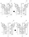
여기서, 구속 롤 (20) 을 상기 서술한 예보다 크게 이동시키는 경우에 대해 설명한다. 금속판 (S) 의 조성, 판두께, 반송 속도 등이 대폭 변화된 경우에는, 금속판 (S) 의 구속 위치 (RP) 에 구속 롤 (20) 을 위치시키기 위해서는, 구속 롤 (20) 을 150 mm 이상 이동시킬 필요가 있다. 구속 롤 (20) 을 150 mm 이상 이동시키는 구성에 대해 설명한다. 도 9 는, 본 발명의 실시형태에 관련된 ??칭 장치의 다른 예를 나타내는 도면이다. 도 9 에 나타내는 ??칭 장치 (50) 는, 구속 롤 (20) 을 이동시키는 롤 이동 장치 (30) 에 추가하여, 노즐 (12) 을 이동시키는 노즐 이동 장치 (60) 를 구비하고 있다. 노즐 이동 장치 (60) 는, 도 9(A) 에 나타내는 바와 같이, 금속판 (S) 의 양측에 각각 배치되어 있다. 노즐 이동 장치 (60) 는, 금속판 (S) 을 따라 노즐 (12) 을 이동시키고, 또한, 금속판 (S) 에 대해서 노즐 (12) 을 접근 및 이격시키도록 구성되어 있다. 또한, 도 9 에 나타내는 예에서는, 금속판 (S) 의 양측의 구속 롤 (20) 은, 상하 방향으로 오프셋되어 있다.Here, a case where the
도 9 에 나타내는 바와 같이, 노즐 이동 장치 (60) 는, 각 노즐 (12) 의 각각에 연통된 냉각 배관 (61) 을 냉각 장치 (10) 의 상하 방향으로 이동시키는 승강 장치 (62) 와, 승강 장치 (62) 를 금속판 (S) 에 대해서 접근 및 이격시키는 슬라이더 (63) 를 구비하고 있다. 승강 장치 (62) 는, 복수의 냉각 배관 (61) 의 각각을 서로 독립적으로 승강 가능하게 구성되어 있다. 또한, 승강 장치 (62) 나 슬라이더 (63) 는 종래 알려진 것이어도 된다. 또한, 승강 장치 (62) 나 슬라이더 (63) 의 구동을 제어하는 도시하지 않은 제어 장치가 형성되어 있다.As shown in FIG. 9, the
다음으로, 도 9 에 나타내는 ??칭 장치 (50) 의 작용에 대해 설명한다. 구속 롤 (20) 을 도 9(A) 에 나타내는 위치로부터 상방으로 이동시키는 경우에는, 당해 구속 롤 (20) 과, 그 상측에 위치하는 노즐 (12) 이 서로 간섭한다. 그 때문에, 먼저, 냉각 장치 (10) 의 폭 방향 (도 9 에서의 좌우 방향) 에 있어서, 슬라이더 (63) 에 의해 금속판 (S) 으로부터 노즐 (12) 을 이격시킨다. 즉, 구속 롤 (20) 에 대하여 노즐 (12) 을 퇴피 이동시킨다. 금속판 (S) 으로부터 노즐 (12) 을 이격시킨 후에 있어서의 금속판 (S) 과 노즐 (12) 의 선단부 사이의 간격은, 구속 롤 (20) 과 노즐 (12) 의 선단부가 서로 접하지 않는 간격으로 설정되어 있다. 그 상태에서 구속 롤 (20) 을 상측 혹은 하측으로 이동시킨다. 도 9 는 상측으로 이동시킨 경우를 도시하고 있다. 즉, 금속판 (S) 의 목표 온도 T2 에 알맞는 위치 (RP) 로 구속 롤 (20) 을 이동시킨다. 도 9(B) 는, 그 상태를 나타내고 있다.Next, the operation of the
또한, 도 9(B) 에 나타내는 상태에서는, 냉각조 (11) 의 폭 방향에 있어서, 구속 롤 (20) 과 노즐 (12) 이 서로 인접하고 있다. 그로 인해, 상기 폭 방향에서 구속 롤 (20) 과 서로 인접하고 있는 노즐 (12) 을, 도 9(B) 에 나타내는 바와 같이, 승강 장치 (62) 에 의해 구속 롤 (20) 의 하측으로 퇴피 이동시킨다. 이로써, 상하 방향과 폭 방향의 어디에 있어서도, 구속 롤 (20) 과 노즐 (12) 은 서로 간섭하지 않도록 되어 있다. 도 9(C) 는, 그 상태를 나타내고 있다. 이어서, 슬라이더 (63) 에 의해 금속판 (S) 에 대하여 각 노즐 (12) 을 접근시켜, 이것들 사이의 간격이 미리 설정된 간격으로 됨과 함께, 유지된다. 이렇게 하여 구속 롤 (20) 의 이동이 완료된다. 도 9(D) 는 그 상태를 나타내고 있다.Moreover, in the state shown in FIG. 9(B), the
또한, 도 9(D) 에 나타내는 상태가 된 후에, 도 1 에 나타내는 예와 거의 동일하게, 노즐 (12) 끼리 사이의 간격을 10 mm ∼ 150 mm 정도로 넓히고, 또한, 그 상태에서, 10 mm ∼ 150 mm 정도, 구속 롤 (20) 을 이동시켜 상기의 위치 (RP) 로 조정해도 된다. 또한, 냉각 능력에 있어서 허용되는 것이라면, 구속 롤 (20) 이 150 mm 이상 이동할 수 있도록, 금속판 (S) 과 노즐 (12) 사이의 간격을 넓힌 상태를 유지해도 된다.Additionally, after the state shown in FIG. 9(D) is reached, almost the same as the example shown in FIG. 1, the gap between the
상기 실시형태에 의하면, 구속 롤 (20) 을 반송 방향을 따라 이동 가능하게 설치함으로써, 냉각 개시 위치로부터 구속 롤 (20) 까지의 거리를 제어하여, 금속판 (S) 의 제조 조건에 상관없이, 목표 온도 T2 의 금속판 (S) 을 구속 롤 (20) 에 의해 구속할 수 있다. 그 결과, 연속 어닐링 설비에 있어서, ??칭시에 발생하는 금속판 (S) 의 제조 조건에 따른 금속판 (S) 의 형상 불량을 억제할 수 있게 된다.According to the above embodiment, by installing the
즉, ??칭 장치 (1) 로 반송하는 금속판 (S) 의 온도는, 예를 들면, 반송 속도 v, 금속판 (S) 의 냉각 개시 온도 T1, 금속판 (S) 의 판두께 t 등의 금속판의 제조 조건에 따라서 편차가 있다. 따라서, 거리 d 가 제조 조건에 관계없이 일정하게 설정되어 있는 경우, 구속 롤 (20) 에 도달했을 때의 금속판 (S) 의 온도에도 편차가 생기게 된다.That is, the temperature of the metal plate S conveyed by the quenching device 1 is, for example, the conveyance speed v, the cooling start temperature T1 of the metal plate S, and the plate thickness t of the metal plate S. There are variations depending on manufacturing conditions. Therefore, when the distance d is set to be constant regardless of manufacturing conditions, variations also occur in the temperature of the metal plate S when it reaches the restraining
이 문제를 해소하기 위해서, 제조 조건에 따라서 상이한 최적 온도 위치에서 적확하게 형상 제어하기 위해서는, 구속 롤 (20) 의 위치를 변화시키는 것이 효과적임을 알아내었다. 구속 롤 (20) 자체가 이동함으로써, 냉각 형태의 불안정함을 초래하지 않고, 제조 조건이 변화되어도 목적으로 하는 온도 범위에서 금속판 (S) 을 구속할 수 있다.In order to solve this problem, it was found that it is effective to change the position of the
특히, 금속판 (S) 의 급랭 중에 마텐자이트 변태가 일어나 조직이 체적 팽창할 때에 발생하는 복잡하고 불균일한 요철 형상을 저감시킬 수 있다. 따라서, 금속판 (S) 이 고강도 강판 (하이텐) 일 때에, 특히 변형 억제 효과가 커진다. 구체적으로, 인장 강도가 580 MPa 이상인 강판의 제조에 적용하는 것이 바람직하다. 인장 강도의 상한은 특별히 제한되지 않지만, 일례로서 2000 MPa 이하이면 된다. 상기의 고강도 강판 (하이텐) 으로는, 고강도 냉연 강판, 및 그것들에 표면 처리를 실시한 용융 아연 도금 강판, 전기 아연 도금 강판, 합금화 용융 아연 도금 강판 등이 있다.In particular, the complex and uneven uneven shape that occurs when martensitic transformation occurs during rapid cooling of the metal plate S and the tissue expands in volume can be reduced. Therefore, when the metal plate S is a high-strength steel plate (High Ten), the deformation suppression effect becomes particularly large. Specifically, it is desirable to apply it to the production of steel sheets with a tensile strength of 580 MPa or more. The upper limit of the tensile strength is not particularly limited, but may be 2000 MPa or less as an example. The above-mentioned high-strength steel sheets (high-strength steel sheets) include high-strength cold-rolled steel sheets, hot-dip galvanized steel sheets that have been subjected to surface treatment, electro-galvanized steel sheets, and alloyed hot-dip galvanized steel sheets.
또한, 고강도 강판의 조성의 구체예로서, 질량% 로, C 가 0.04 % 이상 0.35 % 이하, Si 가 0.01 % 이상 2.50 % 이하, Mn 이 0.80 % 이상 3.70 % 이하, P 가 0.001 % 이상 0.090 % 이하, S 가 0.0001 % 이상 0.0050 % 이하, sol.Al 이 0.005 % 이상 0.065 % 이하, 필요에 따라서, Cr, Mo, Nb, V, Ni, Cu, 및 Ti 중 적어도 1 종 이상이 각각 0.5 % 이하, 추가로 필요에 따라서, B, Sb 가 각각 0.01 % 이하, 잔부가 Fe 및 불가피적 불순물로 이루어지는 예를 들 수 있다. 또한, 금속판 (S) 은, 강판에 한정되는 것은 아니고, 강판 이외의 금속판이어도 된다.In addition, as a specific example of the composition of the high-strength steel sheet, in mass%, C is 0.04% to 0.35%, Si is 0.01% to 2.50%, Mn is 0.80% to 3.70%, and P is 0.001% to 0.090%. , S is 0.0001% or more and 0.0050% or less, sol.Al is 0.005% or more and 0.065% or less, and, if necessary, at least one of Cr, Mo, Nb, V, Ni, Cu, and Ti is each 0.5% or less, Additionally, if necessary, there may be an example where B and Sb are each 0.01% or less, and the balance is Fe and inevitable impurities. In addition, the metal plate S is not limited to a steel plate, and may be a metal plate other than a steel plate.
실시예 1Example 1
본 발명의 실시예를 서술한다. 본 발명예로서, 상기 본 발명의 실시형태에 관련된 ??칭 장치 (1) 를 사용하여, 판두께 t 가 1.0 mm, 판폭이 1000 mm 인 인장 강도 1470 MPa 급의 고장력 냉연 강판의 ??칭을 실시하였다. 인장 강도 1470 MPa 급의 고장력 냉연 강판의 조성으로서, 질량% 로, C 가 0.20 %, Si 가 1.0 %, Mn 이 2.3 %, P 가 0.005 %, S 가 0.002 % 로 하였다. 고장력 냉연 강판의 Ms 점의 온도 TMs 는 300 ℃ 이고, Mf 점의 온도 TMf 는 250 ℃ 이다. 따라서, 구속 롤 (20) 의 통과시의 목표 온도 T2 는, 450 ℃ ∼ 100 ℃ 의 범위에서 설정하면 되며, 목표 온도 T2 를 400 ℃ 로 하였다. 또한, 냉각 개시 온도 T1 을 800 ℃, 목표 온도 T2 를 400 ℃ 로 하였다. 냉각 유체 (CF) 의 온도는 30 ℃ 이고, 냉각 속도 CV 는 1500 (℃/s) 으로 설정하였다.An embodiment of the present invention is described. As an example of the present invention, using the quenching device (1) related to the embodiment of the present invention, quenching of a high-strength cold-rolled steel sheet with a tensile strength of 1470 MPa class with a sheet thickness t of 1.0 mm and a sheet width of 1000 mm is performed. It was carried out. The composition of the high-strength cold-rolled steel sheet with a tensile strength of 1470 MPa class was set as 0.20% by mass, 1.0% Si, 2.3% Mn, 0.005% P, and 0.002% S. The temperature TMs of the Ms point of the high-strength cold rolled steel sheet is 300°C, and the temperature TMf of the Mf point is 250°C. Therefore, the target temperature T2 when passing the
제조 조건의 변화로서, 반송 속도 v 를 1000 ∼ 3000 mm/s 사이에서 변화시키고, 식 (1) 에 기초하여, 반송 속도 v 의 변화에 맞춰 거리 d (mm) 를 d = 267 ∼ 800 m 로 제어하였다. 냉각 후의 강판을 길이 방향 (즉, 강판의 반송 방향과 동일 방향) 에서 100 m 간격으로 10 장 채취하고, 각각의 강판의 휨량을 조사하였다. 도 2 는, 휨량의 정의의 일례를 나타내는 모식도이다. 도 2 에 나타내는 바와 같이, 휨량은, 강판을 수평면에 두었을 때에, 접지면으로부터 가장 높은 위치까지의 높이를 휨량으로 하였다.As a change in manufacturing conditions, the conveyance speed v is changed between 1000 and 3000 mm/s, and based on equation (1), the distance d (mm) is controlled to d = 267 to 800 m according to the change in conveyance speed v. did. Ten sheets of the cooled steel sheet were sampled at intervals of 100 m in the longitudinal direction (i.e., in the same direction as the conveyance direction of the steel sheet), and the amount of warpage of each steel sheet was examined. Figure 2 is a schematic diagram showing an example of the definition of the amount of deflection. As shown in FIG. 2, the amount of deflection was defined as the height from the ground contact surface to the highest position when the steel plate was placed on a horizontal surface.
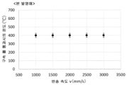
도 3 은, 본 발명예에 있어서의 반송 속도 v 와 목표 온도의 관계를 나타내는 그래프이고, 도 4 는 본 발명예에 있어서의 반송 속도 v 와 금속판 (S) 으로서의 강판의 휨량의 관계를 나타내는 그래프이다. 도 3 에 나타내는 바와 같이, 반송 속도 v 가 변화되어도, 반송 속도 v 에 따라 구속 롤 (20) 을 이동시켜 거리 d 를 변화시킴으로써, 구속 롤 (20) 의 통과시의 온도 (℃) 는 목표 온도 400±25 ℃ 에서 모두 제어할 수 있었다. 그 결과, 도 4 에 나타내는 바와 같이, 강판의 휨량은 모두 10 mm 이하까지 저감되었다. 이것에 의해, 휨량의 편차 즉 최대값과 최소값의 차가 4.2 mm 로 억제되었다.FIG. 3 is a graph showing the relationship between the conveyance speed v and the target temperature in the example of the present invention, and FIG. 4 is a graph showing the relationship between the conveyance speed v and the amount of warpage of the steel plate as the metal plate S in the example of the present invention. . As shown in FIG. 3, even if the conveyance speed v changes, by moving the
도 5 는, 비교예 1 에 있어서의 반송 속도 v 와 목표 온도의 관계를 나타내는 그래프이고, 도 6 은 비교예 1 에 있어서의 반송 속도 v 와 금속판 (S) 으로서의 강판의 휨량의 관계를 나타내는 그래프이다. 비교예 1 로서, 특허문헌 1 과 같은 구속 롤 (20) 이 고정된 ??칭 장치를 사용하고, 그 밖의 조건은 상기 본 발명예와 동일하게 하였다. 비교예 1 에서는, 냉각 개시 위치로부터 구속 롤 (20) 까지의 거리 d (mm) 는 d = 400 mm 로 일정하게 하였다.FIG. 5 is a graph showing the relationship between the conveyance speed v and the target temperature in Comparative Example 1, and FIG. 6 is a graph showing the relationship between the conveyance speed v and the amount of bending of the steel plate as the metal plate S in Comparative Example 1. . As Comparative Example 1, a quenching device with a
비교예 1 에서는, 도 5 에 나타내는 바와 같이, 반송 속도 v (mm/s) 에 의해, 구속 롤 통과시의 온도 (℃) 는 크게 변화하여, 제어할 수 없었다. 그 때문에, v = 1000 mm/s 와 v = 1500 mm/s 이외의 조건에서는, 구속 롤 (20) 의 통과시의 온도 (℃) 가 450 ℃ ∼ 100 ℃ 의 범위를 벗어나 버렸다. 그 결과, 도 6 에 나타내는 바와 같이, v = 1000 mm/s 와 v = 1500 mm/s 이외의 조건에서는, 강판의 휨량이 모두 10 mm 이상이 되어, 변형 억제 효과가 불충분하였다. 그 결과, 휨량의 최대값과 최소값의 차인 편차가 10.3 mm 로 커져 버렸다.In Comparative Example 1, as shown in FIG. 5, the temperature (°C) at the time of passage of the constraint roll varied greatly depending on the conveyance speed v (mm/s) and was not controllable. Therefore, under conditions other than v = 1000 mm/s and v = 1500 mm/s, the temperature (°C) when passing the
도 7 은, 비교예 2 에 있어서의 반송 속도 v 와 목표 온도의 관계를 나타내는 그래프이고, 도 8 은 비교예 2 에 있어서의 반송 속도 v 와 금속판 (S) 으로서의 강판의 휨량의 관계를 나타내는 그래프이다. 비교예 2 로서, 특허문헌 2 에 나타내는 바와 같이, 구속 롤 (20) 은 고정한 채로 가동 마스킹을 이동시켜 냉각 개시 위치에 의해 거리 d 를 제어하였다. 그 밖의 조건은, 본 발명예와 동일하게 하여, 상기의 고장력 냉연 강판을 제조하였다.FIG. 7 is a graph showing the relationship between the conveyance speed v and the target temperature in Comparative Example 2, and FIG. 8 is a graph showing the relationship between the conveyance speed v and the amount of warpage of the steel plate as the metal plate S in Comparative Example 2. . As Comparative Example 2, as shown in
도 7 에 나타내는 바와 같이, 비교예 2 에서는, 반송 속도 v (mm/s) 라는 강판의 제조 조건에 상관없이, 구속 롤 (20) 의 통과시의 온도 (℃) 는 크게 변화하여, 제어할 수 없었다. 그 때문에, 모든 조건에서, 구속 롤 통과시의 온도 (℃) 가 450 ℃ ∼ 100 ℃ 의 범위를 벗어나 버렸다. 그리고, 도 8 에 나타내는 바와 같이, 강판의 휨량이 10 mm 이상이 되어, 변형 억제 효과가 불충분하였다. 그 결과, 휨량의 편차 (최대값과 최소값의 차) 가 9.2 mm 로 커져 버렸다.As shown in FIG. 7, in Comparative Example 2, regardless of the steel sheet manufacturing conditions such as conveyance speed v (mm/s), the temperature (°C) at the time of passage of the restraining
또한, 본 발명의 실시형태는 상기 실시형태에 한정되지 않고, 다양한 변경을 추가할 수 있다. 예를 들어, 상기의 실시형태에서는, 목표 온도 T2 가 (TMs+150) (℃) ∼ (TMf-150) (℃) 인 경우에 대해 예시하고 있지만, 이것에 한정되지 않는다. 후공정에서의 처리나 조업의 자유도의 확보 등의 점에서, 예를 들어 휨량 등의 금속판 (S) 의 형상의 편차가 없으면 된다고 하는 경우에는, 목표 온도 T2 를 (TMs+150) (℃) ∼ (TMf-150) (℃) 로 한정하지 않아도 된다.Additionally, the embodiment of the present invention is not limited to the above embodiment, and various changes can be added. For example, in the above embodiment, the case where the target temperature T2 is (TMs+150) (°C) to (TMf-150) (°C) is exemplified, but it is not limited to this. In the case where there is no variation in the shape of the metal plate S, such as the amount of warpage, for example, in terms of processing in the post-process or ensuring freedom of operation, the target temperature T2 is set to (TMs+150) (°C) to (TMf). There is no need to limit it to -150) (℃).
이 경우, 후공정에서의 처리나 조업의 자유도의 확보 등을 염두에 두면서, 예측되는 형상 (예를 들면, 휨량) 을 고려하여, 목표 온도 T2 를 미리 정해 두고, 구속 롤 (20) 의 위치 조정에 의해, 냉각 개시 위치로부터 구속 롤 (20) 까지의 거리 d 를 제어한다. 그리고, 구속 롤 (20) 통과시의 금속판 (S) 의 온도가 미리 정한 온도 T2 가 되도록 하고, 금속판 (S) 의 형상 (예를 들어, 휨량) 이 동일 정도, 예를 들어 도 2 에서 정의하는 휨량의 편차가 4 mm 이내가 되도록 하면 된다.In this case, the target temperature T2 is set in advance in consideration of the predicted shape (e.g., amount of deflection), and the position of the restraining
또한, 구속 롤 (20) 은 한 쌍으로 한정되는 것은 아니고, 복수 쌍 혹은, 복수 개 형성되어도 된다. 그 경우에는, 구속 롤 쌍 전체를 일괄하여 위치 제어해도 되고, 복수의 구속 롤마다 위치나 개폐를 제어하는 기구로 해도 된다.In addition, the restraining
1 : 금속판의 ??칭 장치
10 : 냉각 장치
11 : 냉각조
12 : 노즐
20 : 구속 롤
30 : 롤 이동 장치
40 : 이동 제어 장치
BD : 반송 방향
CF : 냉각 유체
S : 금속판1: Metal plate quenching device
10: Cooling device
11: cooling tank
12: nozzle
20: Restraint Roll
30: roll moving device
40: movement control device
BD: Transport direction
CF: Cooling fluid
S: metal plate
Claims (15)
반송하는 상기 금속판을 냉각하는 냉각 장치와,
상기 냉각 장치에 의해 냉각된 상기 금속판을 두께 방향으로 구속하면서 반송하는 구속 롤과,
상기 구속 롤을 상기 금속판의 반송 방향을 따라 이동시키는 롤 이동 장치와,
상기 롤 이동 장치의 동작을 제어하여 상기 구속 롤의 위치를 조정하는 이동 제어 장치를 구비하는, 금속판의 ??칭 장치.A metal plate cooling device that cools the metal plate while transporting it,
a cooling device that cools the metal plate being transported;
a restraining roll that conveys the metal plate cooled by the cooling device while restraining it in the thickness direction;
a roll moving device that moves the constraint roll along a conveyance direction of the metal plate;
A quenching device for a metal plate, comprising a movement control device that controls the operation of the roll movement device to adjust the position of the constraint roll.
상기 냉각 장치는, 상기 금속판에 냉각 유체를 분사하여 냉각하는 복수의 노즐을 갖는, 금속판의 ??칭 장치.According to claim 1,
The cooling device is a quenching device for a metal plate, including a plurality of nozzles that spray cooling fluid on the metal plate to cool it.
상기 냉각 장치는, 상기 금속판을 침지시켜 냉각하는 냉각조를 갖는, 금속판의 ??칭 장치.The method of claim 1 or 2,
The cooling device is a metal plate quenching device that has a cooling tank for cooling the metal plate by immersing it.
상기 이동 제어 장치는, 상기 롤 이동 장치의 동작을 제어하여, 상기 금속판이 목표 온도로 되는 위치에서 상기 구속 롤이 상기 금속판을 구속하도록, 상기 구속 롤을 위치 결정하는, 금속판의 ??칭 장치.The method according to any one of claims 1 to 3,
The movement control device controls the operation of the roll moving device to position the restraint roll so that the restraint roll restrains the metal plate at a position where the metal plate reaches the target temperature.
상기 목표 온도는, 상기 금속판의 마텐자이트 변태가 개시되는 Ms 점의 온도를 TMs (℃), 마텐자이트 변태가 종료되는 Mf 점의 온도를 TMf (℃) 로 했을 때, (TMs+150) (℃) ∼ (TMf-150) (℃) 의 온도 범위로 설정되는, 금속판의 ??칭 장치.According to claim 4,
The target temperature is (TMs+150) (°C) when the temperature at the Ms point where the martensite transformation of the metal plate starts is TMs (°C), and the temperature at the Mf point where the martensite transformation ends is TMf (°C). ) A quenching device for metal plates set to a temperature range of (TMf-150) (°C).
상기 이동 제어 장치는, 상기 냉각 장치에 의한 냉각 개시 위치로부터 상기 구속 롤까지의 거리를, 상기 금속판의 반송 속도와, 상기 냉각 장치에 의한 냉각 개시시의 상기 금속판의 냉각 개시 온도와, 상기 목표 온도와, 상기 금속판의 냉각 속도에 기초하여 설정하고, 설정한 거리가 되도록 상기 구속 롤의 위치를 이동시키는, 금속판의 ??칭 장치.The method of claim 4 or 5,
The movement control device determines the distance from the cooling start position by the cooling device to the constraint roll, the conveyance speed of the metal plate, the cooling start temperature of the metal plate at the start of cooling by the cooling device, and the target temperature. and a metal plate quenching device that sets the cooling rate of the metal plate and moves the position of the constraint roll to a set distance.
상기 이동 제어 장치는, 상기 금속판의 반송 속도를 v (mm/s), 냉각 개시 온도를 T1 (℃), 상기 목표 온도를 T2 (℃), 상기 냉각 장치에 의한 상기 금속판의 냉각 속도를 CV (℃/s) 로 했을 때, 상기 냉각 개시 위치로부터 상기 구속 롤까지의 거리 d (mm) 를 식 (1) 에서 구하는, 금속판의 ??칭 장치.
d = (T1-T2)×v/CV (1)According to claim 6,
The movement control device sets the conveyance speed of the metal plate to v (mm/s), the cooling start temperature to T1 (°C), the target temperature to T2 (°C), and the cooling rate of the metal plate by the cooling device to CV ( A quenching device for a metal plate in which the distance d (mm) from the cooling start position to the constraint roll is determined from equation (1) when expressed in °C/s).
d = (T1-T2)×v/CV (1)
상기 이동 제어 장치에는, 상기 냉각 속도 CV 가 상기 금속판의 냉각 조건을 나타내는 계수 α 와 상기 금속판의 판두께 t 에 의해, CV = α/t 로서 설정되어 있는, 금속판의 ??칭 장치.According to claim 7,
In the movement control device, the cooling rate CV is set as CV = α/t by a coefficient α representing the cooling condition of the metal plate and the plate thickness t of the metal plate.
냉각한 상기 금속판을 구속 롤에 의해 두께 방향으로 구속할 때, 상기 금속판이 목표 온도로 되어 있는 위치에서 상기 금속판을 구속하도록, 상기 구속 롤을 상기 금속판의 반송 방향을 따라서 이동시키는, 금속판의 ??칭 방법.As a method of cooling a metal plate while transporting the metal plate,
When restraining the cooled metal plate in the thickness direction with a restraining roll, the restraining roll is moved along the conveyance direction of the metal plate so as to restrain the metal plate at the position where the metal plate is at the target temperature. Ching method.
상기 목표 온도는, 상기 금속판의 마텐자이트 변태가 개시되는 Ms 점의 온도를 TMs (℃), 마텐자이트 변태가 종료되는 Mf 점의 온도를 TMf (℃) 로 했을 때, (TMs+150) (℃) ∼ (TMf-150) (℃) 의 온도 범위로 설정되는, 금속판의 ??칭 방법.According to clause 9,
The target temperature is (TMs+150) (°C) when the temperature at the Ms point where the martensite transformation of the metal plate starts is TMs (°C), and the temperature at the Mf point where the martensite transformation ends is TMf (°C). ) A method of quenching a metal plate, set in a temperature range of (TMf-150) (°C).
상기 구속 롤의 이동은, 상기 금속판의 반송 속도와, 냉각 개시시의 상기 금속판의 냉각 개시 온도와, 상기 목표 온도와, 상기 금속판의 냉각 속도에 기초하여, 냉각 개시 위치로부터 상기 구속 롤까지의 거리를 설정하고,
설정한 거리가 되도록 상기 구속 롤을 이동시킴으로써 실시하는, 금속판의 ??칭 방법.According to claim 9 or 10,
The movement of the restraint roll is based on the conveyance speed of the metal plate, the cooling start temperature of the metal plate at the start of cooling, the target temperature, and the cooling rate of the metal plate, and the distance from the cooling start position to the restraint roll. Set ,
A method of quenching a metal plate, which is carried out by moving the constraint roll to reach a set distance.
상기 냉각 개시 위치로부터 상기 구속 롤까지의 거리는, 상기 금속판의 반송 속도를 v (mm/s), 냉각 개시 온도를 T1 (℃), 상기 목표 온도를 T2 (℃), 상기 금속판의 냉각 속도를 CV (℃/s) 로 했을 때, 상기 냉각 개시 위치로부터 상기 구속 롤까지의 거리 d (mm) 를 식 (1) 에서 구하는, 금속판의 ??칭 방법.
d = (T1-T2)×v/CV (1)According to claim 11,
The distance from the cooling start position to the constraint roll is v (mm/s) as the conveyance speed of the metal plate, T1 (°C) as the cooling start temperature, T2 (°C) as the target temperature, and CV as the cooling rate of the metal plate. A method of quenching a metal plate in which the distance d (mm) from the cooling start position to the constraint roll is determined from equation (1) when expressed in (°C/s).
d = (T1-T2)×v/CV (1)
상기 냉각 속도 CV 는, 상기 금속판의 냉각 조건을 나타내는 계수 α 와 상기 금속판의 판두께 t 에 의해, CV = α/t 로서 설정되어 있는, 금속판의 ??칭 방법.According to claim 12,
The cooling rate CV is set as CV = α/t by the coefficient α representing the cooling condition of the metal plate and the plate thickness t of the metal plate.
Applications Claiming Priority (3)
| Application Number | Priority Date | Filing Date | Title |
|---|---|---|---|
| JPJP-P-2021-136141 | 2021-08-24 | ||
| JP2021136141 | 2021-08-24 | ||
| PCT/JP2022/029364 WO2023026773A1 (en) | 2021-08-24 | 2022-07-29 | Quenching device, quenching method, and metal sheet manufacturing method |
Publications (1)
| Publication Number | Publication Date |
|---|---|
| KR20240035542A true KR20240035542A (en) | 2024-03-15 |
Family
ID=85323012
Family Applications (1)
| Application Number | Title | Priority Date | Filing Date |
|---|---|---|---|
| KR1020247004915A KR20240035542A (en) | 2021-08-24 | 2022-07-29 | Quenching device and method and manufacturing method of metal plate |
Country Status (5)
| Country | Link |
|---|---|
| EP (1) | EP4372105A1 (en) |
| JP (1) | JP7464143B2 (en) |
| KR (1) | KR20240035542A (en) |
| CN (1) | CN117813405A (en) |
| WO (1) | WO2023026773A1 (en) |
Citations (2)
| Publication number | Priority date | Publication date | Assignee | Title |
|---|---|---|---|---|
| JPS6094722U (en) | 1983-12-02 | 1985-06-28 | 日立電線株式会社 | undercarpet cable |
| JP2019090106A (en) | 2017-11-15 | 2019-06-13 | Jfeスチール株式会社 | Rapid cooling hardening apparatus and rapid cooling hardening method, and manufacturing method for metal plate product |
Family Cites Families (4)
| Publication number | Priority date | Publication date | Assignee | Title |
|---|---|---|---|---|
| JPH0718753Y2 (en) * | 1991-03-18 | 1995-05-01 | 中外炉工業株式会社 | Vertical continuous heat treatment furnace for non-ferrous strips |
| JP2011184773A (en) * | 2010-03-10 | 2011-09-22 | Kobe Steel Ltd | Continuous annealing apparatus, and method for suppressing corrugation deformation of metal sheet during quenching in the same |
| JP5928412B2 (en) | 2013-06-19 | 2016-06-01 | Jfeスチール株式会社 | Steel plate vertical cooling device and method for producing hot dip galvanized steel plate using the same |
| JP6094722B2 (en) | 2014-11-28 | 2017-03-15 | Jfeスチール株式会社 | Metal plate manufacturing method and quench quenching apparatus |
-
2022
- 2022-07-29 JP JP2022559513A patent/JP7464143B2/en active Active
- 2022-07-29 WO PCT/JP2022/029364 patent/WO2023026773A1/en active Application Filing
- 2022-07-29 EP EP22861064.8A patent/EP4372105A1/en active Pending
- 2022-07-29 CN CN202280055945.6A patent/CN117813405A/en active Pending
- 2022-07-29 KR KR1020247004915A patent/KR20240035542A/en unknown
Patent Citations (2)
| Publication number | Priority date | Publication date | Assignee | Title |
|---|---|---|---|---|
| JPS6094722U (en) | 1983-12-02 | 1985-06-28 | 日立電線株式会社 | undercarpet cable |
| JP2019090106A (en) | 2017-11-15 | 2019-06-13 | Jfeスチール株式会社 | Rapid cooling hardening apparatus and rapid cooling hardening method, and manufacturing method for metal plate product |
Also Published As
| Publication number | Publication date |
|---|---|
| JP7464143B2 (en) | 2024-04-09 |
| CN117813405A (en) | 2024-04-02 |
| WO2023026773A1 (en) | 2023-03-02 |
| JPWO2023026773A1 (en) | 2023-03-02 |
| EP4372105A1 (en) | 2024-05-22 |
Similar Documents
| Publication | Publication Date | Title |
|---|---|---|
| JP6094722B2 (en) | Metal plate manufacturing method and quench quenching apparatus | |
| JP6687084B2 (en) | Quenching and quenching apparatus, quenching and quenching method, and method for manufacturing metal plate product | |
| CN108474052B (en) | Quenching apparatus and quenching method | |
| US20100258216A1 (en) | Method for annealing a strip of steel having a variable thickness in length direction | |
| JP6870701B2 (en) | Steel sheet cooling method, steel sheet cooling device and steel sheet manufacturing method | |
| KR20240035542A (en) | Quenching device and method and manufacturing method of metal plate | |
| EP3395964A1 (en) | Method and device for manufacturing martensite-containing steel sheet | |
| WO2020203261A1 (en) | Quenching device and metal sheet manufacturing method | |
| WO2023026774A1 (en) | Quench-hardening apparatus, quench-hardening method, and metal sheet manufacturing method | |
| JP2019099916A (en) | Quenching device and quenching method, and metal plate product manufacturing method | |
| JP6295387B1 (en) | Controlled cooling method for hot-rolled steel bars | |
| JP7355251B2 (en) | Metal plate quenching equipment, continuous annealing equipment, metal plate quenching method, cold rolled steel plate production method, and galvanized steel plate production method | |
| WO2023042795A1 (en) | Quenching apparatus, continuous annealing facility, quenching method, steel sheet production method, and plated steel sheet production method | |
| WO2021065583A1 (en) | Metal strip quenching device, metal strip quenching method, and method for producing metal strip product | |
| JP7306590B1 (en) | Quenching equipment, continuous annealing equipment, quenching method, steel sheet manufacturing method, and plated steel sheet manufacturing method | |
| JP7060003B2 (en) | Steel sheet cooling method, steel sheet manufacturing method, and steel sheet cooling equipment | |
| US20170298463A1 (en) | Method for producing metal band material with different mechanical properties across the width of the band | |
| KR20240021278A (en) | Quenching device, quenching method, manufacturing method of cold rolled steel sheet, and manufacturing method of plated steel sheet | |
| KR20170091549A (en) | Method and apparatus for manufacturing steel sheet having martensite phase |