JP7464143B2 - Quenching device, quenching method, and method of manufacturing metal plate - Google Patents
Quenching device, quenching method, and method of manufacturing metal plate Download PDFInfo
- Publication number
- JP7464143B2 JP7464143B2 JP2022559513A JP2022559513A JP7464143B2 JP 7464143 B2 JP7464143 B2 JP 7464143B2 JP 2022559513 A JP2022559513 A JP 2022559513A JP 2022559513 A JP2022559513 A JP 2022559513A JP 7464143 B2 JP7464143 B2 JP 7464143B2
- Authority
- JP
- Japan
- Prior art keywords
- metal plate
- cooling
- roll
- quenching
- temperature
- Prior art date
- Legal status (The legal status is an assumption and is not a legal conclusion. Google has not performed a legal analysis and makes no representation as to the accuracy of the status listed.)
- Active
Links
- 239000002184 metal Substances 0.000 title claims description 234
- 229910052751 metal Inorganic materials 0.000 title claims description 234
- 238000010791 quenching Methods 0.000 title claims description 61
- 230000000171 quenching effect Effects 0.000 title claims description 59
- 238000000034 method Methods 0.000 title claims description 36
- 238000004519 manufacturing process Methods 0.000 title claims description 19
- 238000001816 cooling Methods 0.000 claims description 124
- 230000000452 restraining effect Effects 0.000 claims description 46
- 230000009466 transformation Effects 0.000 claims description 20
- 239000012809 cooling fluid Substances 0.000 claims description 18
- 229910000734 martensite Inorganic materials 0.000 claims description 17
- 238000005246 galvanizing Methods 0.000 claims description 4
- 229910000831 Steel Inorganic materials 0.000 description 24
- 239000010959 steel Substances 0.000 description 24
- 230000000052 comparative effect Effects 0.000 description 13
- XLYOFNOQVPJJNP-UHFFFAOYSA-N water Substances O XLYOFNOQVPJJNP-UHFFFAOYSA-N 0.000 description 12
- 230000032258 transport Effects 0.000 description 9
- 239000010960 cold rolled steel Substances 0.000 description 7
- 230000008859 change Effects 0.000 description 6
- 238000010586 diagram Methods 0.000 description 6
- 238000000137 annealing Methods 0.000 description 5
- 239000007788 liquid Substances 0.000 description 5
- 230000000873 masking effect Effects 0.000 description 5
- 229910001335 Galvanized steel Inorganic materials 0.000 description 3
- 230000008602 contraction Effects 0.000 description 3
- 230000007547 defect Effects 0.000 description 3
- 239000008397 galvanized steel Substances 0.000 description 3
- 230000007246 mechanism Effects 0.000 description 3
- 239000000203 mixture Substances 0.000 description 3
- 239000007921 spray Substances 0.000 description 3
- 230000001629 suppression Effects 0.000 description 3
- 238000009835 boiling Methods 0.000 description 2
- 238000002474 experimental method Methods 0.000 description 2
- 229910052748 manganese Inorganic materials 0.000 description 2
- 239000000463 material Substances 0.000 description 2
- 230000008569 process Effects 0.000 description 2
- 238000002791 soaking Methods 0.000 description 2
- 240000006829 Ficus sundaica Species 0.000 description 1
- -1 and at the same time Substances 0.000 description 1
- 229910052804 chromium Inorganic materials 0.000 description 1
- 239000000110 cooling liquid Substances 0.000 description 1
- 239000000498 cooling water Substances 0.000 description 1
- 229910052802 copper Inorganic materials 0.000 description 1
- 230000006378 damage Effects 0.000 description 1
- 230000002950 deficient Effects 0.000 description 1
- 230000000694 effects Effects 0.000 description 1
- 238000005244 galvannealing Methods 0.000 description 1
- 230000005484 gravity Effects 0.000 description 1
- 239000012535 impurity Substances 0.000 description 1
- 230000002452 interceptive effect Effects 0.000 description 1
- 238000012423 maintenance Methods 0.000 description 1
- 238000012986 modification Methods 0.000 description 1
- 230000004048 modification Effects 0.000 description 1
- 229910052750 molybdenum Inorganic materials 0.000 description 1
- 229910052759 nickel Inorganic materials 0.000 description 1
- 229910052758 niobium Inorganic materials 0.000 description 1
- 238000012545 processing Methods 0.000 description 1
- 230000002829 reductive effect Effects 0.000 description 1
- 230000004043 responsiveness Effects 0.000 description 1
- 230000002441 reversible effect Effects 0.000 description 1
- 238000005096 rolling process Methods 0.000 description 1
- 238000004381 surface treatment Methods 0.000 description 1
- 229910052719 titanium Inorganic materials 0.000 description 1
- 229910052720 vanadium Inorganic materials 0.000 description 1
- 239000013585 weight reducing agent Substances 0.000 description 1
Images


Classifications
-
- B—PERFORMING OPERATIONS; TRANSPORTING
- B21—MECHANICAL METAL-WORKING WITHOUT ESSENTIALLY REMOVING MATERIAL; PUNCHING METAL
- B21B—ROLLING OF METAL
- B21B45/00—Devices for surface or other treatment of work, specially combined with or arranged in, or specially adapted for use in connection with, metal-rolling mills
- B21B45/02—Devices for surface or other treatment of work, specially combined with or arranged in, or specially adapted for use in connection with, metal-rolling mills for lubricating, cooling, or cleaning
-
- C—CHEMISTRY; METALLURGY
- C21—METALLURGY OF IRON
- C21D—MODIFYING THE PHYSICAL STRUCTURE OF FERROUS METALS; GENERAL DEVICES FOR HEAT TREATMENT OF FERROUS OR NON-FERROUS METALS OR ALLOYS; MAKING METAL MALLEABLE, e.g. BY DECARBURISATION OR TEMPERING
- C21D1/00—General methods or devices for heat treatment, e.g. annealing, hardening, quenching or tempering
- C21D1/18—Hardening; Quenching with or without subsequent tempering
-
- C—CHEMISTRY; METALLURGY
- C21—METALLURGY OF IRON
- C21D—MODIFYING THE PHYSICAL STRUCTURE OF FERROUS METALS; GENERAL DEVICES FOR HEAT TREATMENT OF FERROUS OR NON-FERROUS METALS OR ALLOYS; MAKING METAL MALLEABLE, e.g. BY DECARBURISATION OR TEMPERING
- C21D1/00—General methods or devices for heat treatment, e.g. annealing, hardening, quenching or tempering
- C21D1/62—Quenching devices
- C21D1/63—Quenching devices for bath quenching
-
- C—CHEMISTRY; METALLURGY
- C21—METALLURGY OF IRON
- C21D—MODIFYING THE PHYSICAL STRUCTURE OF FERROUS METALS; GENERAL DEVICES FOR HEAT TREATMENT OF FERROUS OR NON-FERROUS METALS OR ALLOYS; MAKING METAL MALLEABLE, e.g. BY DECARBURISATION OR TEMPERING
- C21D1/00—General methods or devices for heat treatment, e.g. annealing, hardening, quenching or tempering
- C21D1/62—Quenching devices
- C21D1/667—Quenching devices for spray quenching
-
- C—CHEMISTRY; METALLURGY
- C21—METALLURGY OF IRON
- C21D—MODIFYING THE PHYSICAL STRUCTURE OF FERROUS METALS; GENERAL DEVICES FOR HEAT TREATMENT OF FERROUS OR NON-FERROUS METALS OR ALLOYS; MAKING METAL MALLEABLE, e.g. BY DECARBURISATION OR TEMPERING
- C21D9/00—Heat treatment, e.g. annealing, hardening, quenching or tempering, adapted for particular articles; Furnaces therefor
- C21D9/52—Heat treatment, e.g. annealing, hardening, quenching or tempering, adapted for particular articles; Furnaces therefor for wires; for strips ; for rods of unlimited length
- C21D9/54—Furnaces for treating strips or wire
- C21D9/56—Continuous furnaces for strip or wire
- C21D9/573—Continuous furnaces for strip or wire with cooling
-
- C—CHEMISTRY; METALLURGY
- C22—METALLURGY; FERROUS OR NON-FERROUS ALLOYS; TREATMENT OF ALLOYS OR NON-FERROUS METALS
- C22C—ALLOYS
- C22C38/00—Ferrous alloys, e.g. steel alloys
- C22C38/02—Ferrous alloys, e.g. steel alloys containing silicon
-
- C—CHEMISTRY; METALLURGY
- C22—METALLURGY; FERROUS OR NON-FERROUS ALLOYS; TREATMENT OF ALLOYS OR NON-FERROUS METALS
- C22C—ALLOYS
- C22C38/00—Ferrous alloys, e.g. steel alloys
- C22C38/04—Ferrous alloys, e.g. steel alloys containing manganese
-
- C—CHEMISTRY; METALLURGY
- C22—METALLURGY; FERROUS OR NON-FERROUS ALLOYS; TREATMENT OF ALLOYS OR NON-FERROUS METALS
- C22C—ALLOYS
- C22C38/00—Ferrous alloys, e.g. steel alloys
-
- C—CHEMISTRY; METALLURGY
- C22—METALLURGY; FERROUS OR NON-FERROUS ALLOYS; TREATMENT OF ALLOYS OR NON-FERROUS METALS
- C22C—ALLOYS
- C22C38/00—Ferrous alloys, e.g. steel alloys
- C22C38/60—Ferrous alloys, e.g. steel alloys containing lead, selenium, tellurium, or antimony, or more than 0.04% by weight of sulfur
Description
本発明は、金属板を連続的に搬送しながら焼鈍を行う焼入れ装置及び焼入れ方法並びに金属板の製造方法に関する。The present invention relates to a quenching apparatus and a quenching method for annealing a metal plate while continuously transporting the metal plate, and a method for manufacturing a metal plate.
金属板を連続的に搬送しながら焼鈍を行う連続焼鈍設備において、金属板が加熱後に冷却されて相変態を起こすことにより、金属板組織の造り込みが行われる。特に、自動車業界では車体の軽量化と衝突安全性の両立を目的として、薄肉化した高張力鋼板(ハイテン)の需要が増している。高張力鋼板の製造時には、鋼板を急速に冷却する技術が重要となる。金属板の冷却速度が最も速い技術の1つとして、水焼入れ法が知られている。水焼入れ法では、加熱された金属板が水中に浸漬すると同時に、水中内に設けられたクエンチノズルにより冷却水が金属板に噴射されることで、金属板の焼入れが行われる。In a continuous annealing facility where metal sheets are annealed while being continuously transported, the metal sheets are heated and then cooled to cause a phase transformation, thereby forming a metal sheet structure. In particular, in the automotive industry, there is an increasing demand for thin-walled high-tensile steel sheets (hi-tensile) in order to achieve both weight reduction and crashworthiness of the car body. When manufacturing high-tensile steel sheets, a technique for rapidly cooling the steel sheet is important. Water quenching is known as one of the techniques that can cool metal sheets at the fastest rate. In the water quenching method, the heated metal sheet is immersed in water, and at the same time, cooling water is sprayed onto the metal sheet from a quench nozzle installed in the water, thereby quenching the metal sheet.
金属板の焼入れ時には、金属板に反りや波状変形等の形状不良が発生する。これは、急冷されることによる金属板の熱収縮等に起因する。特に、金属板の温度が、マルテンサイト変態が開始する温度Msからマルテンサイト変態が終了する温度Mfとなったときに、急激な熱収縮と変態膨張が同時に生じる。During quenching of a metal sheet, defects in shape such as warping and wavy deformation occur in the metal sheet. This is due to thermal contraction of the metal sheet caused by rapid cooling. In particular, when the temperature of the metal sheet changes from the temperature Ms at which martensitic transformation starts to the temperature Mf at which martensitic transformation ends, rapid thermal contraction and transformation expansion occur simultaneously.
そこで、従来から、焼入れ時における金属板の形状不良を防止するために様々な手法が提案されている(例えば特許文献1、2参照)。特許文献1には、金属板のマルテンサイト変態が開始するMs点の温度をTMs(℃)、マルテンサイト変態が終了するMf点の温度をTMf(℃)としたとき、金属板の温度が(TMs+150)(℃)から(TMf-150)(℃)範囲において、冷却液体中に設けられた一対の拘束ロールにより金属板を拘束する手法が提案されている。Therefore, various methods have been proposed to prevent the shape defects of metal sheets during quenching (see, for example, Patent Documents 1 and 2). Patent Document 1 proposes a method in which a metal sheet is restrained by a pair of restraining rolls provided in a cooling liquid when the temperature of the metal sheet is in the range of (TMs+150) (°C) to (TMf-150) (°C), where TMs (°C) is the temperature of the Ms point at which the martensitic transformation of the metal sheet starts, and TMf (°C) is the temperature of the Mf point at which the martensitic transformation ends.
特許文献2には、金属板の表面に複数の水噴出ノズルから水を噴射することで冷却する焼入れ方法を行う際に、拘束ロールによって金属板を拘束しつつ、可動マスキングによって冷却流体による金属板の冷却開始位置と拘束ロールとの距離を制御することが開示されている。さらに、特許文献1と同様、金属板のマルテンサイト変態が開始するMs点の温度をTMs(℃)、マルテンサイト変態が終了するMf点の温度をTMf(℃)としたとき、金属板を(TMs+150)(℃)~(TMf-150)(℃)の温度で拘束ロールを通過させる手法が提案されている。
しかしながら、特許文献1に記載された方法では、金属板の製造条件によって、金属板の温度が(TMs+150)(℃)~(TMf-150)(℃)の範囲となる位置が変化する。このため、金属板の温度が(TMs+150)(℃)~(TMf-150)(℃)となる位置で拘束ロールが金属板を拘束できず、金属板の形状にバラツキが発生してしまう可能性がある。However, in the method described in Patent Document 1, the position where the temperature of the metal sheet is in the range of (TMs+150) (°C) to (TMf-150) (°C) changes depending on the manufacturing conditions of the metal sheet. For this reason, the restraining rolls cannot restrain the metal sheet at the position where the temperature of the metal sheet is in the range of (TMs+150) (°C) to (TMf-150) (°C), and there is a possibility that variation occurs in the shape of the metal sheet.
特許文献2に記載された方法では、可動マスキングに衝突した水が重力によって落下し、可動マスキングの下部の水噴出ノズルから噴射された水に干渉することで、金属板の冷却能力が不安定になる。また、ノズルごとにマスキングされるため、冷却能力が段階的に(非連続的に)に変わり、その結果、金属板の温度が(TMs+150)(℃)~(TMf-150)(℃)となる位置が不安定になり、金属板の形状にバラツキが発生してしまう可能性がある。In the method described in
本発明は、このような課題を解決するためになされたものであり、金属板を拘束する位置での金属板の温度を高精度に制御し、焼入れ時に発生する金属板の形状のバラツキを抑制することができる焼入れ装置及び焼入れ方法並びに金属板製品の製造方法を提供することを目的とする。The present invention has been made to solve these problems, and aims to provide a hardening device and hardening method, as well as a manufacturing method for metal plate products, that can control the temperature of a metal plate at the position where the metal plate is restrained with high precision and suppress variation in the shape of the metal plate that occurs during hardening.
[1] 金属板を搬送しながら冷却する金属板の焼入れ装置であって、搬送する前記金属板を冷却する冷却装置と、前記冷却装置により冷却された前記金属板を厚み方向に拘束しながら搬送する拘束ロールと、前記拘束ロールを前記金属板の搬送方向に沿って移動させるロール移動装置と、前記ロール移動装置の動作を制御して前記拘束ロールの位置を調整する移動制御装置と、を備える金属板の焼入れ装置。
[2] 前記冷却装置は、前記金属板に冷却流体を噴射して冷却する複数のノズルを有する[1]に記載の金属板の焼入れ装置。
[3] 前記冷却装置は、前記金属板を浸漬させて冷却する冷却槽を有する[1]又は[2]に記載の金属板の焼入れ装置。
[4] 前記移動制御装置は、前記ロール移動装置の動作を制御し、前記金属板が目標温度になる位置で前記拘束ロールが前記金属板を拘束するように、前記拘束ロールを位置決めする[1]~[3]のいずれかに記載の金属板の焼入れ装置。
[5] 前記目標温度は、前記金属板のマルテンサイト変態が開始するMs点の温度をTMs(℃)、マルテンサイト変態が終了するMf点の温度をTMf(℃)としたとき、(TMs+150)(℃)~(TMf-150)(℃)の温度範囲に設定される[4]に記載の金属板の焼入れ装置。
[6] 前記移動制御装置は、前記冷却装置による冷却開始位置から前記拘束ロールまでの距離を、前記金属板の搬送速度と、前記冷却装置による冷却開始時の前記金属板の冷却開始温度と、前記目標温度と、前記金属板の冷却速度とに基づいて設定し、設定した距離になるように前記拘束ロールの位置を移動させる[4]又は[5]に記載の金属板の焼入れ装置。
[7] 前記移動制御装置は、前記金属板の搬送速度をv(mm/s)、冷却開始温度をT1(℃)、前記目標温度をT2(℃)、前記冷却装置による前記金属板の冷却速度をCV(℃/s)としたとき、前記冷却開始位置から前記拘束ロールまでの距離d(mm)を式(1)で求める[6]に記載の金属板の焼入れ装置。
d=(T1-T2)×v/CV (1)
[8] 前記移動制御装置には、前記冷却速度CVが前記金属板の冷却条件を示す係数αと前記金属板の板厚tによって、CV=α/tとして設定されている[7]に記載の金属板の焼入れ装置。
[9] 金属板を搬送しながら冷却する金属板の焼入れ方法であって、冷却した前記金属板を拘束ロールによって厚み方向に拘束するとき、前記金属板が目標温度になっている位置で前記金属板を拘束するように、前記拘束ロールを搬送方向に沿って移動させる金属板の焼入れ方法。
[10] 前記目標温度は、前記金属板のマルテンサイト変態が開始するMs点の温度をTMs(℃)、マルテンサイト変態が終了するMf点の温度をTMf(℃)としたとき、(TMs+150)(℃)~(TMf-150)(℃)の温度範囲に設定される[9]に記載の金属板の焼入れ方法。
[11] 前記拘束ロールの移動は、前記金属板の搬送速度と、冷却開始時の前記金属板の冷却開始温度と、前記目標温度と、前記金属板の冷却速度とに基づいて、冷却開始位置から前記拘束ロールまでの距離を設定し、設定した距離になるように前記拘束ロールを移動させることで行う[9]又は[10]に記載の金属板の焼入れ方法。
[12] 前記冷却開始位置から前記拘束ロールまでの距離は、前記金属板の搬送速度をv(mm/s)、冷却開始温度をT1(℃)、前記目標温度をT2(℃)、前記金属板の冷却速度をCV(℃/s)としたとき、前記冷却開始位置から前記拘束ロールまでの距離d(mm)を式(1)で求める[11]に記載の金属板の焼入れ方法。
d=(T1-T2)×v/CV (1)
[13] 前記冷却速度CVは、前記金属板の冷却条件を示す係数αと前記金属板の板厚tによって、CV=α/tとして設定されている[12]記載の金属板の焼入れ方法。
[14] [9]~[13]のいずれかに記載の金属板の焼入れ方法を用いる、高強度冷延鋼板の製造方法。
[15] [14]に記載の方法で得られた高強度鋼板に、溶融亜鉛めっき処理、電気亜鉛めっき処理、もしくは合金化溶融亜鉛めっき処理のいずれかを行う高強度鋼板の製造方法。[1] A metal plate quenching apparatus that cools a metal plate while transporting the metal plate, the metal plate quenching apparatus comprising: a cooling device that cools the metal plate being transported; a constraint roll that transports the metal plate cooled by the cooling device while constraining it in a thickness direction; a roll moving device that moves the constraint roll along the transport direction of the metal plate; and a movement control device that controls the operation of the roll moving device to adjust the position of the constraint roll.
[2] The metal plate quenching apparatus according to [1], wherein the cooling device has a plurality of nozzles that spray a cooling fluid onto the metal plate to cool it.
[3] The metal plate quenching apparatus according to [1] or [2], wherein the cooling device has a cooling tank in which the metal plate is immersed and cooled.
[4] The metal plate quenching device according to any one of [1] to [3], wherein the movement control device controls the operation of the roll movement device and positions the constraint roll so that the constraint roll constrains the metal plate at a position where the metal plate reaches a target temperature.
[5] The metal plate quenching device according to [4], wherein the target temperature is set in a temperature range of (TMs+150) (°C) to (TMf-150) (°C), where TMs (°C) is the temperature of the Ms point at which the martensitic transformation of the metal plate starts, and TMf (°C) is the temperature of the Mf point at which the martensitic transformation ends.
[6] The metal plate quenching device according to [4] or [5], wherein the movement control device sets a distance from a position where cooling by the cooling device starts to the restraint roll based on the conveying speed of the metal plate, the cooling start temperature of the metal plate when cooling by the cooling device starts, the target temperature, and the cooling rate of the metal plate, and moves the position of the restraint roll so that the set distance is achieved.
[7] The metal plate quenching device according to [6], wherein the movement control device calculates a distance d (mm) from the cooling start position to the restraint roll using equation (1), where v (mm/s) is a conveying speed of the metal plate, T1 (°C), T2 (°C), and CV (°C/s) is a cooling rate of the metal plate by the cooling device.
d = (T1 - T2) x v / CV (1)
[8] The metal plate quenching device according to [7], wherein the movement control device has a cooling rate CV set as CV=α/t, where α is a coefficient indicating the cooling conditions of the metal plate and t is a plate thickness of the metal plate.
[9] A method for quenching a metal plate in which the metal plate is cooled while being transported, wherein when the cooled metal plate is constrained in the thickness direction by constraining rolls, the constraining rolls are moved along a transport direction so as to constrain the metal plate at a position where the metal plate is at a target temperature.
[10] The method for quenching a metal plate according to [9], wherein the target temperature is set in a temperature range of (TMs+150) (°C) to (TMf-150) (°C), where TMs (°C) is the temperature of the Ms point at which martensitic transformation of the metal plate starts, and TMf (°C) is the temperature of the Mf point at which martensitic transformation ends.
[11] The method for quenching a metal plate according to [9] or [10], wherein the movement of the restraining roll is performed by setting a distance from a cooling start position to the restraining roll based on a conveying speed of the metal plate, a cooling start temperature of the metal plate at the start of cooling, the target temperature, and a cooling rate of the metal plate, and moving the restraining roll to the set distance.
[12] The quenching method of the metal plate according to [11], wherein the distance d (mm) from the cooling start position to the constraining roll is calculated by Equation (1) when the conveying speed of the metal plate is v (mm/s), the cooling start temperature is T1 (°C), the target temperature is T2 (°C), and the cooling rate of the metal plate is CV (°C/s).
d = (T1 - T2) x v / CV (1)
[13] The method for quenching a metal plate according to [12], wherein the cooling rate CV is set as CV=α/t, where α indicates a cooling condition of the metal plate and t is a thickness of the metal plate.
[14] A method for producing a high-strength cold-rolled steel sheet, using the method for quenching a metal sheet according to any one of [9] to [13].
[15] A method for producing a high-strength steel sheet, comprising subjecting the high-strength steel sheet obtained by the method according to [14] to any one of hot-dip galvanizing, electrogalvanizing, and galvannealing.
本発明によれば、金属板の焼入れ時に、金属板の温度に合わせて拘束ロールの位置を金属板の搬送方向に沿って調整することにより、冷却開始位置から拘束ロールまでの距離を制御して、焼入れ時に発生する金属板の形状のバラツキを抑制することができる。According to the present invention, when quenching a metal plate, the position of the restraint roll is adjusted along the transport direction of the metal plate in accordance with the temperature of the metal plate, thereby controlling the distance from the cooling start position to the restraint roll, thereby suppressing variation in the shape of the metal plate that occurs during quenching.
本発明の実施形態を図面に基づいて説明する。図1は本発明の実施形態に係る焼入れ装置を示す模式図である。なお、図1の焼入れ装置1は、例えば金属板Sとして鋼材の焼入れを行うものであって、連続焼鈍炉の均熱帯の出側に設けられた冷却設備に適用される。図1の金属板Sの焼入れ装置1は、金属板Sを冷却する冷却装置10と、冷却された金属板Sを厚み方向に拘束する拘束ロール20とを備える。An embodiment of the present invention will be described with reference to the drawings. Fig. 1 is a schematic diagram showing a quenching apparatus according to an embodiment of the present invention. The quenching apparatus 1 of Fig. 1 is for quenching a steel material as a metal sheet S, for example, and is applied to a cooling facility provided on the outlet side of a soaking zone of a continuous annealing furnace. The quenching apparatus 1 for a metal sheet S of Fig. 1 includes a
冷却装置10は、冷却流体CFを用いて金属板Sを冷却するものであり、冷却流体CFを貯留する冷却槽11と、冷却槽11内に設置され、金属板Sの表面へ冷却流体CFを噴射する複数のノズル12とを備える。冷却槽11には冷却流体CFとして水が貯留されており、例えば冷却槽11の上面から金属板Sが搬送方向BDに向かって浸漬していく。なお、冷却槽11内には、金属板Sの搬送方向を変更するシンクロール2が設置されている。The
複数のノズル12は、例えばクエンチノズル等からなり、金属板Sの両面側のそれぞれに金属板Sの搬送方向に沿って設置されている。よって、金属板Sは、冷却槽11内の冷却流体CF及び複数のノズル12から噴射される冷却流体CFによって冷却される。このように、冷却槽11と複数のノズル12の双方を用いて金属板Sを冷却することにより、金属板Sの表面の沸騰状態を安定させ、均一な形状制御を行うことができる。The
なお、冷却流体CFとして水を用いた水焼入れの場合について例示しているが、冷却流体CFとして油を用いた油冷であっても良い。また、図1において、複数のノズル12が冷却槽11内に設置されている場合について例示しているが、金属板Sを所望の温度範囲で冷却できる手法であれば、冷却方法はこれに限定されない。例えば、金属板Sを冷却槽11だけで冷却してもよいし、複数のノズル12だけで冷却するようにしてもよい。Although the example shows a case where water quenching is performed using water as the cooling fluid CF, oil cooling using oil as the cooling fluid CF may be used. In addition, although the example shows a case where
冷却槽11内にノズル12を設置する場合、液体焼入れによる急速冷却において金属板Sとノズル12との間の距離は重要である。沸騰現象により発生する蒸気膜を液体噴流で破壊することで急速冷却を行うため、ノズル12は金属板Sに近接して設置することが望ましい。ノズル12の先端部と金属板Sとの間の距離は、好ましくは10mm以上150mm以内である。10mm未満の場合、変形してバタついた金属板Sとノズル12とが接触する可能性がある。また150mmを超える場合、蒸気膜の破壊効果が弱くなり、十分な冷却能力を確保することが困難となる可能性がある。When the
拘束ロール20は、冷却装置10により冷却された金属板Sを厚み方向に拘束するものであって、冷却槽11内の金属板Sの両面にそれぞれ設置されている。なお、図1においては、1対の拘束ロール20が対向するように設置されているが、拘束するものであれば搬送方向に沿ってずれた位置に設置されていてもよい。また、図1では1対の拘束ロール20が設置されている場合について例示しているが、搬送方向に沿って複数の1対の拘束ロール20が設置されていてもよい。The
また、拘束ロール20のロール径はロール剛性と拘束応力に伴うたわみとの相関から、好ましくは、50mm以上300mm以内である。拘束ロール20の材質は限定されない。拘束ロール20として一般的な鋼ロールを用いた場合であって、ロール径が50mm未満の場合には、ロール剛性が不足し、たわみにより金属板Sに対し均一な拘束力を作用させることが困難となり、破損の可能性がある。また、ロール径が300mmよりも大きい場合には、ノズル12からの噴流が金属板Sに到達しない区間が長くなり、蒸気膜の破壊が不十分となり、冷却能力が低下する可能性がある。In addition, the roll diameter of the
拘束ロール20は、金属板Sの搬送方向に沿って、移動可能に設置されている。ここで、搬送方向とは金属板Sが搬送される方向を指す。具体的には、金属板Sの焼入れ装置1は、拘束ロール20を移動させるロール移動装置30と、拘束ロール20の移動を制御する移動制御装置40とを備える。ロール移動装置30は、例えばモータ等の公知の駆動手段を備えており、金属板Sの搬送方向に沿って、拘束ロール20を金属板Sの搬送方向BD、あるいは搬送方向BDとは逆方向へ移動させるように構成されている。具体的には、ロール移動装置30は、パワージャッキ、ネジ機構やギヤ機構によるスクリュー式昇降装置、また、転がりを利用する抵抗の少ないLinear Motion Guide(LMガイド)等の機械
部品の組み合わせることで好適に製作できる。図1には、スクリュー式昇降装置によってロール移動装置30を構成した例を示してある。L字形状のアーム31の一方の端部に拘束ロール20が回転可能に取り付けられている。アーム31の他方の端部側にネジ部32と、ネジ部32に噛み合う他のネジ部と、他のネジ部を駆動する駆動手段(それぞれ図示せず)とが設けられている。駆動手段は固定部(図示せず)に固定されている。したがって、駆動手段で発生させたトルクを受けて他のネジ部が回転すると、それに伴って搬送方向BDと互いに平行な方向にアーム31が移動する。 The restraining
上述した駆動手段が液体に浸漬すると、当該駆動手段のメンテナンスが困難となる可能性がある。そのため、駆動手段は、冷却槽11の液面よりも上方に設置されることが好ましい。また、駆動手段は、高温となる炉内から遮蔽された空間に設置されることが好ましい。If the driving means is immersed in the liquid, maintenance of the driving means may become difficult. Therefore, the driving means is preferably installed above the liquid level of the
ロール移動装置30は、拘束ロール20を金属板Sの厚み方向へ移動させ、金属板Sの拘束及び拘束の解除を行う機能を有していてもよい。また、移動させることができれば特に手法を問わないが、応答性を考慮すれば電動式がより好ましい。The
移動制御装置40は、コンピュータ等のハードウェア資源からなっており、拘束ロール20の移動を制御する。特に、移動制御装置40は、ロール移動装置30の動作を制御し、金属板Sが目標温度になる位置RPで拘束されるように、拘束ロール20を位置決めする。ここで、目標温度は、金属板Sのマルテンサイト変態が開始するMs点の温度をTMs(℃)、マルテンサイト変態が終了するMf点の温度をTMf(℃)としたとき、(TMs+150)(℃)~(TMf-150)(℃)の温度範囲に設定されることが好ましい。これにより、金属板Sに急激な熱収縮と変態膨張とが同時に生じる位置で、金属板Sの変形を拘束ロール20によって拘束することができ、焼入れ時の金属板Sの変形を抑制することができる。The
移動制御装置40は、冷却流体CFによる金属板Sの冷却開始位置SPから拘束ロール20で拘束する目標温度になる位置RPまでの距離dを算出し、算出した距離dに基づいて拘束ロール20を移動させる。この際、移動制御装置40は、金属板Sの搬送速度v(mm/s)、冷却開始温度T1(℃)、拘束ロール20で拘束する目標温度T2(℃)、冷却装置10による金属板Sの冷却速度CV(℃/s)を用いて距離dを算出する。ここで、冷却開始温度T1は、冷却流体CFによって金属板Sの冷却を開始する冷却開始位置SP直前での金属板Sの温度である。例えば、冷却開始位置SPや焼入れ装置1に至るまでの金属板Sの冷却状況に基づいて、冷却開始位置SPに到達する直前の温度を算出することができる。具体的には、連続焼鈍炉の均熱帯の出側において、非接触タイプの温度計によって金属板Sの温度を測定する。そして、その温度と、焼入れ装置1に到達するまでの金属板Sの自然冷却による温度低下分とに基づいて冷却開始位置SPに到達する直前あるいは到達時点の金属板Sの温度を算出することができる。上述した金属板Sの自然冷却による温度低下分は、実験によって予め求めることができる。なお、上記パラメータは、プロセスコンピューターの設定値、あるいは操業実績値から逐次取得してもよいし、速度センサもしくは温度センサ等を用いて実測してもよい。The
具体的には、距離dと冷却速度CV(℃/s)の関係は下記(1)式で表される。Specifically, the relationship between the distance d and the cooling rate CV (° C./s) is expressed by the following formula (1).
CV=(T1-T2)/(d/v)
d=(T1-T2)×v/CV ・・・(1) CV=(T1-T2)/(d/v)
d = (T1 - T2) x v / CV (1)
冷却速度CV(℃/s)は、ノズル形状、又は噴射される冷却流体CFの種類、温度及び噴射量等の冷却条件を示す係数α(℃・mm/s)と、金属板Sの板厚tとを用いて下記(3)式で表すことができる。The cooling rate CV (°C/s) can be expressed by the following equation (3) using a coefficient α (°C·mm/s) indicating cooling conditions such as the nozzle shape, or the type, temperature, and amount of cooling fluid CF sprayed, and the plate thickness t of the metal plate S.
CV=α/t ・・・(2)CV=α/t (2)
(1)式に(2)式を代入すると、距離dは下記(3)式で表すことができる。By substituting equation (2) into equation (1), the distance d can be expressed by the following equation (3).
d=(T1-T2)×v×t/α ・・・(3)d = (T1 - T2) x v x t / α ... (3)
移動制御装置40には、事前に実験や数値解析等によって求められた冷却速度CV(℃/s)、もしくはα(℃・mm/s)が記憶されている。そして、移動制御装置40は、(1)式もしくは(3)式を用いて距離dを求め、求めた距離dの位置で金属板Sを拘束するように、拘束ロール20を移動させる。なお、冷却速度CVは、板厚等に応じて定まる値であり、板厚1~2mmでは冷却速度CV=1000~2000(℃/s)となり、α=500~2000(℃・mm/s)である。そこで、移動制御装置40において、冷却速度CVが上記範囲の中間の1500(℃/s)に設定されていてもよい。この場合は、αを中間値の1250(℃・mm/s)として扱ってもよい。このように、上述した冷却速度CVと板厚tと式(2)によって求められる冷却条件αが設定されていてもよい。The
図1を参照して本発明の焼入れ方法及び金属板Sの製造方法について説明する。まず、金属板Sが搬送されながら冷却装置10によって冷却され、金属板Sの焼入れが行われる。このとき、位置RPで目標温度T2になっている金属板Sの厚み方向を拘束するように、拘束ロール20が搬送方向に沿って移動する。このとき、移動制御装置40において、上記式(1)もしくは式(3)を用いて距離dが算出され、算出された距離dの位置で金属板Sを拘束するように、拘束ロール20が移動する。なお、拘束ロール20の移動は、金属板Sの焼入れをしている最中にも逐次行うことができる。例えば、移動制御装置40は、搬送速度vが変更されたタイミングで距離dの算出及び拘束ロール20の移動を行うようにしてもよい。The quenching method and the manufacturing method of the metal sheet S of the present invention will be described with reference to FIG. 1. First, the metal sheet S is cooled by the cooling
金属板Sの搬送速度は1枚の金属板S(1コイル内)においても変動する。このため、拘束ロール20で金属板Sを拘束したまま、搬送方向あるいは逆方向に移動することができれば、金属板Sの先端・尾端など減速する部分の形状不良による歩留まりを改善できるので、なお好ましい。あるいは、移動制御装置40は、設定された期間毎に距離dの算出及び拘束ロール20の移動を行うようにしてもよい。The conveying speed of the metal sheet S varies even for one metal sheet S (within one coil). For this reason, if the metal sheet S can be moved in the conveying direction or the reverse direction while being restrained by the restraining rolls 20, this is more preferable because it can improve the yield caused by defective shapes in the parts of the metal sheet S that are decelerated, such as the leading and trailing ends. Alternatively, the
距離dに基づく金属板Sの拘束位置RPに、拘束ロール20を調整するための拘束ロール20の移動距離は、現実的には、概ね10mm~150mm程度と見積もることができる。図1に示すように、冷却槽11内にノズル12を設置した場合、ノズル12同士の間隔を10mm~150mm程度に予め広げた状態で、それらのノズル12の間で拘束ロール20を昇降させて良い。また、例えば、液体噴流による急速冷却は1000℃/sec程度の冷却能力であり、金属板Sの走行速度を60m/min(=1000mm/sec)とする場合、100mmの距離で100℃程度変化する。つまり、10mm~150mmの範囲で拘束ロール20の昇降が可能であれば、拘束される金属板Sの温度は10℃~150℃程度調整可能であり、上述した拘束ロール20の移動距離は、現実的には十分な制御調整範囲である。The movement distance of the constraining
ここで、拘束ロール20を上述した例よりも大きく移動させる場合について説明する。金属板Sの組成、板厚、搬送速度などが大幅に変化した場合には、金属板Sの拘束位置RPに拘束ロール20を位置させるためには、拘束ロール20を150mm以上移動させる必要がある。拘束ロール20を150mm以上移動させる構成について説明する。図9は、本発明の実施形態に係る焼入れ装置の他の例を示す図である。図9に示す焼入れ装置50は、拘束ロール20を移動させるロール移動装置30に加えて、ノズル12を移動させるノズル移動装置60を備えている。ノズル移動装置60は、図9(A)に示すように、金属板Sの両側にそれぞれ配置されている。ノズル移動装置60は、金属板Sに沿ってノズル12を移動させ、また、金属板Sに対してノズル12を接近及び離隔させるように構成されている。なお、図9に示す例では、金属板Sの両側の拘束ロール20は、上下方向にオフセットされている。Here, a case where the constraining
図9に示すように、ノズル移動装置60は、各ノズル12のそれぞれに連通された冷却配管61を冷却装置10の上下方向に移動させる昇降装置62と、昇降装置62を金属板Sに対して接近および離隔させるスライダ63とを備えている。昇降装置62は、複数の冷却配管61のそれぞれを互いに独立して昇降可能に構成されている。なお、昇降装置62やスライダ63は従来知られたものであってよい。また。昇降装置62やスライダ63の駆動を制御する図示しない制御装置が設けられている。As shown in Fig. 9, the
次に、図9に示す焼入れ装置50の作用について説明する。拘束ロール20を図9(A)に示す位置から上方に移動させる場合には、当該拘束ロール20と、その上側に位置するノズル12とが互いに干渉する。そのため、先ず、冷却装置10の幅方向(図9での左右方向)において、スライダ63によって金属板Sからノズル12を離隔させる。つまり、拘束ロール20に対してノズル12を退避移動させる。金属板Sからノズル12を離隔させた後における金属板Sとノズル12の先端部との間の間隔は、拘束ロール20とノズル12の先端部とが互いに接しない間隔に設定されている。その状態で拘束ロール20を上側もしくは下側に移動させる。図9は上側に移動させた場合を図示している。すなわち、金属板Sの目標温度T2に適した位置RPに拘束ロール20を移動させる。図9(B)はその状態を示している。Next, the operation of the
また、図9(B)に示す状態では、冷却槽11の幅方向において、拘束ロール20とノズル12とが互いに隣接している。そのため、前記幅方向で拘束ロール20と互いに隣接しているノズル12を、図9(B)に示すように、昇降装置62によって拘束ロール20の下側に退避移動させる。これにより、上下方向と幅方向とのいずれにおいても、拘束ロール20とノズル12とは互いに干渉しないようになっている。図9(C)はその状態を示している。次いで、スライダ63によって金属板Sに対して各ノズル12を接近させ、それらの間の間隔が予め設定された間隔にされると共に、維持される。こうして拘束ロール20の移動が完了する。図9(D)はその状態を示している。In the state shown in FIG. 9(B), the restraining
なお、図9(D)に示す状態となった後に、図1に示す例とほぼ同様に、ノズル12同士の間の間隔を10mm~150mm程度に広げ、かつ、その状態で、10mm~150mm程度、拘束ロール20を移動させて上記の位置RPに調整してよい。また、冷却能力において許容されるのであれば、拘束ロール20が150mm以上移動できるように、金属板Sとノズル12との間の間隔を広げた状態を維持してもよい。9(D), the interval between the
上記実施の形態によれば、拘束ロール20を搬送方向に沿って移動可能に設置することにより、冷却開始位置から拘束ロール20までの距離を制御し、金属板Sの製造条件によらず、目標温度T2の金属板Sを拘束ロール20によって拘束することができる。その結果、連続焼鈍設備において、焼入れ時に発生する金属板Sの製造条件による金属板Sの形状不良を抑制することができるようになる。According to the above embodiment, by installing the constraint rolls 20 movably along the conveyance direction, the distance from the cooling start position to the constraint rolls 20 can be controlled, and the metal sheet S at the target temperature T2 can be constrained by the constraint rolls 20 regardless of the manufacturing conditions of the metal sheet S. As a result, in the continuous annealing equipment, it becomes possible to suppress shape defects of the metal sheet S caused by the manufacturing conditions of the metal sheet S during quenching.
すなわち、焼入れ装置1に搬送する金属板Sの温度は、例えば、搬送速度v、金属板Sの冷却開始温度T1、金属板Sの板厚t等の金属板の製造条件によってばらつきがある。よって、距離dが製造条件に拘わらず一定に設定されている場合、拘束ロール20に到達したときの金属板Sの温度にもばらつきが生じることになる。That is, the temperature of the metal sheet S transported to the quenching device 1 varies depending on the manufacturing conditions of the metal sheet, such as the transport speed v, the cooling start temperature T1 of the metal sheet S, and the thickness t of the metal sheet S. Therefore, if the distance d is set to a constant value regardless of the manufacturing conditions, the temperature of the metal sheet S when it reaches the constraint rolls 20 will also vary.
この問題を解消するために、製造条件によって異なる最適温度位置で的確に形状制御するには、拘束ロール20の位置を変化させることが効果的であることを見出した。拘束ロール20自体が移動することにより、冷却形態の不安定さを招くことなく、製造条件が変化しても目的とする温度範囲で金属板Sを拘束することができる。To solve this problem, it was found that in order to accurately control the shape at an optimal temperature position that differs depending on the manufacturing conditions, it is effective to change the position of the restraining
特に、金属板Sの急冷中にマルテンサイト変態が起こって組織が体積膨張する際に発生する複雑で不均一な凹凸状の形状を低減させることができる。よって、金属板Sが高強度鋼板(ハイテン)のときに、特に変形抑制効果が大きくなる。具体的には、引張強度が580MPa以上である鋼板の製造に適用することが好ましい。引張強度の上限は特に制限されないが、一例として2000MPa以下であればよい。上記の高強度鋼板(ハイテン)としては、高強度冷延鋼板、およびそれらに表面処理を施した溶融亜鉛鍍金鋼板、電気亜鉛鍍金鋼板、合金化溶融亜鉛鍍金鋼板等がある。In particular, it is possible to reduce the complex and uneven uneven shape that occurs when the martensitic transformation occurs during the quenching of the metal sheet S and the structure expands in volume. Therefore, when the metal sheet S is a high-strength steel sheet (hi-tensile), the deformation suppression effect is particularly large. Specifically, it is preferable to apply it to the manufacture of a steel sheet having a tensile strength of 580 MPa or more. The upper limit of the tensile strength is not particularly limited, but as an example, it may be 2000 MPa or less. The above-mentioned high-strength steel sheet (hi-tensile) includes a high-strength cold-rolled steel sheet, and a hot-dip galvanized steel sheet, an electrolytic galvanized steel sheet, an alloyed hot-dip galvanized steel sheet, etc., which are obtained by subjecting the high-strength cold-rolled steel sheet to surface treatment.
なお、高強度鋼板の組成の具体例として、質量%で、Cが0.04%以上0.35%以下、Siが0.01%以上2.50%以下、Mnが0.80%以上3.70%以下、Pが0.001%以上0.090%以下、Sが0.0001%以上0.0050%以下、sol.Alが0.005%以上0.065%以下、必要に応じて、Cr、Mo、Nb、V、Ni、Cu、及びTiの少なくとも1種以上がそれぞれ0.5%以下、さらに必要に応じて、B、Sbがそれぞれ0.01%以下、残部がFe及び不可避的不純物からなる例が挙げられる。尚、金属板Sは、鋼板に限定されるものではなく、鋼板以外の金属板であってもよい。Specific examples of the composition of the high-strength steel plate include, in mass%, C of 0.04% to 0.35%, Si of 0.01% to 2.50%, Mn of 0.80% to 3.70%, P of 0.001% to 0.090%, S of 0.0001% to 0.0050%, sol.Al of 0.005% to 0.065%, and optionally, at least one of Cr, Mo, Nb, V, Ni, Cu, and Ti is 0.5% or less, and further optionally, B and Sb are 0.01% or less, with the balance being Fe and unavoidable impurities. The metal plate S is not limited to a steel plate, and may be a metal plate other than a steel plate.
本発明の実施例を述べる。本発明例として、上記の本発明の実施形態に係る焼入れ装置1を用いて、板厚tが1.0mm、板幅が1000mmの引張強さ1470MPa級の高張力冷延鋼板の焼入れを行った。引張強さ1470MPa級の高張力冷延鋼板の組成として、質量%で、Cが0.20%、Siが1.0%、Mnが2.3%、Pが0.005%、Sが0.002%とした。高張力冷延鋼板のMs点の温度TMsは300℃であり、Mf点の温度TMfは250℃である。よって、拘束ロール20の通過時の目標温度T2は、450℃~100℃の範囲で設定すればよく、目標温度T2を400℃とした。また、冷却開始温度T1を800℃、目標温度T2を400℃とした。冷却流体CFの温度は30℃で、冷却速度CVは1500(℃/s)に設定した。An example of the present invention will be described. As an example of the present invention, a high-tensile cold-rolled steel sheet having a thickness t of 1.0 mm, a width of 1000 mm, and a tensile strength of 1470 MPa was quenched using the quenching device 1 according to the embodiment of the present invention. The composition of the high-tensile cold-rolled steel sheet having a tensile strength of 1470 MPa was, in mass%, 0.20% C, 1.0% Si, 2.3% Mn, 0.005% P, and 0.002% S. The temperature TMs of the Ms point of the high-tensile cold-rolled steel sheet was 300°C, and the temperature TMf of the Mf point was 250°C. Therefore, the target temperature T2 at the time of passing through the restraining
製造条件の変化として、搬送速度vを1000~3000mm/sの間で変化させ、式(1)に基づき、搬送速度vの変化に合わせて距離d(mm)をd=267~800mで制御した。冷却後の鋼板を長手方向(すなわち、鋼板の搬送方向と同じ方向)で100mおきに10枚採取し、それぞれの鋼板の反り量を調査した。図2は、反り量の定義の一例を示す模式図である。図2に示すように、反り量は、鋼板を水平面に置いたときに、接地面から最も高い位置までの高さを反り量とした。As a change in the manufacturing conditions, the conveying speed v was changed between 1000 and 3000 mm/s, and the distance d (mm) was controlled to d = 267 to 800 m according to the change in the conveying speed v based on the formula (1). Ten steel sheets after cooling were sampled at intervals of 100 m in the longitudinal direction (i.e., the same direction as the conveying direction of the steel sheet), and the amount of warping of each steel sheet was investigated. Figure 2 is a schematic diagram showing an example of the definition of the amount of warping. As shown in Figure 2, the amount of warping was defined as the height from the ground surface to the highest point when the steel sheet was placed on a horizontal surface.
図3は、本発明例における搬送速度vと目標温度との関係を示すグラフであり、図4は本発明例における搬送速度vと金属板Sとしての鋼板の反り量との関係を示すグラフである。図3に示すように、搬送速度vが変化しても、搬送速度vに応じて拘束ロール20を移動させて距離dを変化させることにより、拘束ロール20の通過時の温度(℃)は目標温度400±25℃で全て制御できた。その結果、図4に示すように、鋼板の反り量は全て10mm以下にまで低減していた。それにより、反り量のバラツキつまり最大値と最小値との差が4.2mmに抑制された。Fig. 3 is a graph showing the relationship between the conveying speed v and the target temperature in the example of the present invention, and Fig. 4 is a graph showing the relationship between the conveying speed v and the warpage of the steel sheet as the metal sheet S in the example of the present invention. As shown in Fig. 3, even if the conveying speed v changes, the temperature (°C) when passing through the restraining
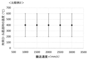
図5は、比較例1における搬送速度vと目標温度との関係を示すグラフであり、図6は比較例1における搬送速度vと金属板Sとしての鋼板の反り量との関係を示すグラフである。比較例1として、特許文献1のような拘束ロール20が固定された焼入れ装置を用い、その他の条件は、上記本発明例と同一とした。比較例1では、冷却開始位置から拘束ロール20までの距離d(mm)はd=400mmで一定とした。Fig. 5 is a graph showing the relationship between the conveying speed v and the target temperature in Comparative Example 1, and Fig. 6 is a graph showing the relationship between the conveying speed v and the warpage of the steel sheet as the metal sheet S in Comparative Example 1. As Comparative Example 1, a quenching device with a fixed constraining
比較例1では、図5に示すように、搬送速度v(mm/s)によって、拘束ロール通過時の温度(℃)は大きく変化し、制御することはできなかった。そのため、v=1000mm/sとv=1500mm/s以外の条件では、拘束ロール20の通過時の温度(℃)が450℃~100℃の範囲を外れてしまった。その結果、図6に示すように、v=1000mm/sとv=1500mm/s以外の条件では、鋼板の反り量が全て10mm以上となり、変形抑制効果が不十分であった。その結果、反り量の最大値と最小値との差であるバラツキが10.3mmと大きくなってしまった。In Comparative Example 1, as shown in FIG. 5, the temperature (°C) when passing through the restraining rolls changed significantly depending on the conveying speed v (mm/s) and could not be controlled. Therefore, under conditions other than v = 1000 mm/s and v = 1500 mm/s, the temperature (°C) when passing through the restraining rolls 20 was out of the range of 450°C to 100°C. As a result, as shown in FIG. 6, under conditions other than v = 1000 mm/s and v = 1500 mm/s, the warpage of the steel sheet was 10 mm or more in all cases, and the deformation suppression effect was insufficient. As a result, the variation, which is the difference between the maximum and minimum values of the warpage, became large at 10.3 mm.
図7は、比較例2における搬送速度vと目標温度との関係を示すグラフであり、図8は比較例2における搬送速度vと金属板Sとしての鋼板の反り量との関係を示すグラフである。比較例2として、特許文献2に示すように、拘束ロール20は固定したまま可動マスキングを移動させて冷却開始位置によって距離dを制御した。その他の条件は、本発明例と同じにして、上記の高張力冷延鋼板を製造した。Fig. 7 is a graph showing the relationship between the conveying speed v and the target temperature in Comparative Example 2, and Fig. 8 is a graph showing the relationship between the conveying speed v and the warpage of the steel sheet as the metal sheet S in Comparative Example 2. In Comparative Example 2, as shown in
図7に示すように、比較例2では、搬送速度v(mm/s)という鋼板の製造条件によらず、拘束ロール20の通過時の温度(℃)は大きく変化し、制御することはできなかった。そのため、全ての条件で、拘束ロール通過時の温度(℃)が450℃~100℃の範囲を外れてしまった。そして、図8に示すように、鋼板の反り量が10mm以上となり、変形抑制効果が不十分であった。その結果、反り量のバラツキ(最大値と最小値との差)が9.2mmと大きくなってしまった。As shown in Fig. 7, in Comparative Example 2, regardless of the manufacturing condition of the steel sheet, namely the conveying speed v (mm/s), the temperature (°C) when passing through the constraining
なお、本発明の実施形態は、上記実施形態に限定されず、種々の変更を加えることができる。例えば、上記の実施形態では、目標温度T2が(TMs+150)(℃)~(TMf-150)(℃)の場合について例示しているが、これに限定されない。後工程での処理や操業の自由度の確保等の点から、例えば反り量等の金属板Sの形状のバラツキが無ければよいという場合には、目標温度T2を(TMs+150)(℃)~(TMf-150)(℃)に限定しなくともよい。The embodiment of the present invention is not limited to the above embodiment, and various modifications can be made. For example, in the above embodiment, the target temperature T2 is exemplified as being between (TMs+150) (°C) and (TMf-150) (°C), but is not limited thereto. In terms of ensuring the flexibility of processing and operation in the post-process, for example, if there is no variation in the shape of the metal sheet S, such as the amount of warping, the target temperature T2 does not have to be limited to (TMs+150) (°C) and (TMf-150) (°C).
この場合、後工程での処理や操業の自由度の確保等を念頭におきながら、予測される形状(例えば、反り量)を考慮して、目標温度T2を予め定めておき、拘束ロール20の位置調整によって、冷却開始位置から拘束ロール20までの距離dを制御する。そして、拘束ロール20通過時の金属板Sの温度が予め定めた温度T2になるようにして、金属板Sの形状(例えば、反り量)が同程度、例えば、図2で定義する反り量のバラツキが4mm以内になるようにすればよい。In this case, a target temperature T2 is determined in advance in consideration of the predicted shape (e.g., the amount of warping) while keeping in mind the treatment in the subsequent process and ensuring the freedom of operation, and the distance d from the cooling start position to the constraining
さらに、拘束ロール20は一対に限定するものではなく、複数対もしくは、複数本設けられて良い。その場合には、拘束ロール対全体をまとめて位置制御しても良いし、複数の拘束ロール毎に位置や開閉を制御する機構としても良い。Furthermore, the number of constraining
1 金属板の焼入れ装置
10 冷却装置
11 冷却槽
12 ノズル
20 拘束ロール
30 ロール移動装置
40 移動制御装置
BD 搬送方向
CF 冷却流体
S 金属板
Reference Signs List 1: Metal plate quenching device 10: Cooling device 11: Cooling tank 12: Nozzle 20: Restraining roll 30: Roller moving device 40: Movement control device BD: Transport direction CF: Cooling fluid S: Metal plate
Claims (14)
搬送する前記金属板に冷却流体を噴射して冷却する複数のノズルを有する冷却装置と、
前記冷却装置により冷却された前記金属板を厚み方向に拘束しながら搬送する拘束ロールと、
前記拘束ロールを前記金属板の搬送方向に沿って移動させるロール移動装置と、
前記ロール移動装置の動作を制御して前記拘束ロールの位置を調整する移動制御装置と、
前記複数のノズルを移動させるノズル移動装置と、を備え、
前記ノズル移動装置は、前記複数のノズルのそれぞれに連通された冷却配管を互いに独立して前記搬送方向に沿って昇降させる昇降装置と、
前記金属板に対して前記複数のノズルを接近および離隔させるスライダと、を有し、
前記スライダは、前記複数のノズルを、前記拘束ロールと前記複数のノズルが前記搬送方向に互いに重なり合う位置、及び、互いに重なり合わない位置に移動可能とする金属板の焼入れ装置。 A metal plate quenching device that cools a metal plate while transporting the metal plate,
a cooling device having a plurality of nozzles for injecting a cooling fluid onto the metal plate being conveyed to cool the metal plate;
A restraining roll that conveys the metal plate cooled by the cooling device while restraining it in a thickness direction;
a roll moving device that moves the restraining roll along a conveying direction of the metal plate;
a movement control device that controls the operation of the roll moving device to adjust the position of the restraining roll;
A nozzle moving device that moves the plurality of nozzles,
the nozzle moving device includes a lifting device that lifts and lowers cooling pipes that are connected to the plurality of nozzles, respectively, along the transport direction independently of each other;
a slider for moving the nozzles toward and away from the metal plate ;
The slider is a metal plate hardening device that can move the multiple nozzles to a position where the restraint roll and the multiple nozzles overlap each other in the conveying direction, and a position where they do not overlap each other .
d=(T1-T2)×v/CV (1) 6. The metal plate quenching device according to claim 5, wherein the movement control device calculates a distance d (mm) from the cooling start position to the restraint roll using equation (1), where v (mm/s) is a conveying speed of the metal plate, T1 (°C) is a cooling start temperature, T2 (°C) is a target temperature, and CV (°C/s) is a cooling rate of the metal plate by the cooling device.
d = (T1 - T2) x v / CV (1)
前記金属板に複数のノズルから冷却流体を噴射して冷却し、当該冷却流体によって冷却した前記金属板を拘束ロールによって厚み方向に拘束するとき、前記金属板が目標温度になっている位置で前記金属板を拘束するように、前記拘束ロールを前記金属板の搬送方向に沿って移動させると共に、
前記搬送方向に沿って前記拘束ロールが移動することによって、前記複数のノズルのうち、前記拘束ロールと干渉するノズルを前記拘束ロールの移動する方向とは反対側に移動させる金属板の焼入れ方法。 A method for quenching a metal plate, comprising the steps of:
a cooling fluid is sprayed from a plurality of nozzles onto the metal plate to cool it, and the metal plate cooled by the cooling fluid is restrained in a thickness direction by a restraining roll, the restraining roll is moved along a conveying direction of the metal plate so as to restrain the metal plate at a position where the metal plate is at a target temperature,
The method for hardening a metal plate includes moving the constraining roll along the conveying direction, thereby moving, among the plurality of nozzles, any nozzle that interferes with the constraining roll to the opposite side to the direction in which the constraining roll moves.
設定した距離になるように前記拘束ロールを移動させることで行う請求項8に記載の金属板の焼入れ方法。 The movement of the restraining roll is performed by setting a distance from a cooling start position to the restraining roll based on a conveying speed of the metal sheet, a cooling start temperature of the metal sheet at the start of cooling, the target temperature, and a cooling speed of the metal sheet;
9. The method for quenching a metal plate according to claim 8, wherein the quenching is performed by moving the restraining rolls to a set distance.
d=(T1-T2)×v/CV (1) 11. The method for quenching a metal plate according to claim 10, wherein a distance d (mm) from the cooling start position to the constraining roll is calculated by Equation (1) where v (mm/s) is a conveying speed of the metal plate, T1 (°C) is a cooling start temperature, T2 (°C) is a target temperature, and CV (°C/s) is a cooling rate of the metal plate.
d = (T1 - T2) x v / CV (1)
Applications Claiming Priority (3)
| Application Number | Priority Date | Filing Date | Title |
|---|---|---|---|
| JP2021136141 | 2021-08-24 | ||
| JP2021136141 | 2021-08-24 | ||
| PCT/JP2022/029364 WO2023026773A1 (en) | 2021-08-24 | 2022-07-29 | Quenching device, quenching method, and metal sheet manufacturing method |
Publications (3)
| Publication Number | Publication Date |
|---|---|
| JPWO2023026773A1 JPWO2023026773A1 (en) | 2023-03-02 |
| JPWO2023026773A5 JPWO2023026773A5 (en) | 2023-08-01 |
| JP7464143B2 true JP7464143B2 (en) | 2024-04-09 |
Family
ID=85323012
Family Applications (1)
| Application Number | Title | Priority Date | Filing Date |
|---|---|---|---|
| JP2022559513A Active JP7464143B2 (en) | 2021-08-24 | 2022-07-29 | Quenching device, quenching method, and method of manufacturing metal plate |
Country Status (4)
| Country | Link |
|---|---|
| JP (1) | JP7464143B2 (en) |
| KR (1) | KR20240035542A (en) |
| CN (1) | CN117813405A (en) |
| WO (1) | WO2023026773A1 (en) |
Citations (3)
| Publication number | Priority date | Publication date | Assignee | Title |
|---|---|---|---|---|
| JP2015004080A (en) | 2013-06-19 | 2015-01-08 | Jfeスチール株式会社 | Vertical cooling device for steel plate, and method of manufacturing galvanized steel plate using the same |
| JP6094722B2 (en) | 2014-11-28 | 2017-03-15 | Jfeスチール株式会社 | Metal plate manufacturing method and quench quenching apparatus |
| JP2019090106A (en) | 2017-11-15 | 2019-06-13 | Jfeスチール株式会社 | Rapid cooling hardening apparatus and rapid cooling hardening method, and manufacturing method for metal plate product |
Family Cites Families (3)
| Publication number | Priority date | Publication date | Assignee | Title |
|---|---|---|---|---|
| JPS6094722U (en) | 1983-12-02 | 1985-06-28 | 日立電線株式会社 | undercarpet cable |
| JPH0718753Y2 (en) * | 1991-03-18 | 1995-05-01 | 中外炉工業株式会社 | Vertical continuous heat treatment furnace for non-ferrous strips |
| JP2011184773A (en) * | 2010-03-10 | 2011-09-22 | Kobe Steel Ltd | Continuous annealing apparatus, and method for suppressing corrugation deformation of metal sheet during quenching in the same |
-
2022
- 2022-07-29 JP JP2022559513A patent/JP7464143B2/en active Active
- 2022-07-29 WO PCT/JP2022/029364 patent/WO2023026773A1/en active Application Filing
- 2022-07-29 KR KR1020247004915A patent/KR20240035542A/en unknown
- 2022-07-29 CN CN202280055945.6A patent/CN117813405A/en active Pending
Patent Citations (3)
| Publication number | Priority date | Publication date | Assignee | Title |
|---|---|---|---|---|
| JP2015004080A (en) | 2013-06-19 | 2015-01-08 | Jfeスチール株式会社 | Vertical cooling device for steel plate, and method of manufacturing galvanized steel plate using the same |
| JP6094722B2 (en) | 2014-11-28 | 2017-03-15 | Jfeスチール株式会社 | Metal plate manufacturing method and quench quenching apparatus |
| JP2019090106A (en) | 2017-11-15 | 2019-06-13 | Jfeスチール株式会社 | Rapid cooling hardening apparatus and rapid cooling hardening method, and manufacturing method for metal plate product |
Also Published As
| Publication number | Publication date |
|---|---|
| JPWO2023026773A1 (en) | 2023-03-02 |
| WO2023026773A1 (en) | 2023-03-02 |
| CN117813405A (en) | 2024-04-02 |
| KR20240035542A (en) | 2024-03-15 |
Similar Documents
| Publication | Publication Date | Title |
|---|---|---|
| JP6094722B2 (en) | Metal plate manufacturing method and quench quenching apparatus | |
| JP6687084B2 (en) | Quenching and quenching apparatus, quenching and quenching method, and method for manufacturing metal plate product | |
| CN108474052B (en) | Quenching apparatus and quenching method | |
| US8864921B2 (en) | Method for annealing a strip of steel having a variable thickness in length direction | |
| JP6422575B2 (en) | Method for intercooling thin steel sheets | |
| EP2700724B1 (en) | Method and apparatus for heat treating rails | |
| KR20150139612A (en) | Method for producing a metal strip | |
| US20120028069A1 (en) | Grain-oriented electrical steel sheet and producing method therefor | |
| JP7464143B2 (en) | Quenching device, quenching method, and method of manufacturing metal plate | |
| JP4695221B1 (en) | Controlled cooling method for flat steel | |
| JP6870701B2 (en) | Steel sheet cooling method, steel sheet cooling device and steel sheet manufacturing method | |
| JP5991282B2 (en) | Steel strip manufacturing method and manufacturing equipment | |
| WO2023026774A1 (en) | Quench-hardening apparatus, quench-hardening method, and metal sheet manufacturing method | |
| KR20230151109A (en) | Continuous annealing equipment, continuous annealing method, cold rolled steel sheet manufacturing method, and plated steel sheet manufacturing method | |
| WO2023042795A1 (en) | Quenching apparatus, continuous annealing facility, quenching method, steel sheet production method, and plated steel sheet production method | |
| JP2019099916A (en) | Quenching device and quenching method, and metal plate product manufacturing method | |
| JP7306590B1 (en) | Quenching equipment, continuous annealing equipment, quenching method, steel sheet manufacturing method, and plated steel sheet manufacturing method | |
| JPWO2020085352A1 (en) | Quenching equipment, quenching method, and steel sheet manufacturing method | |
| EP3395964A1 (en) | Method and device for manufacturing martensite-containing steel sheet | |
| JP4221978B2 (en) | Metal band manufacturing method for preventing waist breakage in metal band manufacturing equipment | |
| JP7060003B2 (en) | Steel sheet cooling method, steel sheet manufacturing method, and steel sheet cooling equipment | |
| WO2023002741A1 (en) | Metal sheet-quenching apparatus, continuous annealing facility, metal sheet-quenching method, cold-rolled steel sheet production method, and plated steel sheet production method | |
| WO2021065583A1 (en) | Metal strip quenching device, metal strip quenching method, and method for producing metal strip product | |
| CN117999366A (en) | Quenching device, continuous annealing apparatus, quenching method, method for producing steel sheet, and method for producing plated steel sheet | |
| JP4389435B2 (en) | Method and apparatus for manufacturing hot-dip metal strip |
Legal Events
| Date | Code | Title | Description |
|---|---|---|---|
| A521 | Request for written amendment filed |
Free format text: JAPANESE INTERMEDIATE CODE: A523 Effective date: 20221018 |
|
| A621 | Written request for application examination |
Free format text: JAPANESE INTERMEDIATE CODE: A621 Effective date: 20221018 |
|
| A131 | Notification of reasons for refusal |
Free format text: JAPANESE INTERMEDIATE CODE: A131 Effective date: 20231024 |
|
| A521 | Request for written amendment filed |
Free format text: JAPANESE INTERMEDIATE CODE: A523 Effective date: 20231124 |
|
| A131 | Notification of reasons for refusal |
Free format text: JAPANESE INTERMEDIATE CODE: A131 Effective date: 20240109 |
|
| A521 | Request for written amendment filed |
Free format text: JAPANESE INTERMEDIATE CODE: A523 Effective date: 20240205 |
|
| TRDD | Decision of grant or rejection written | ||
| A01 | Written decision to grant a patent or to grant a registration (utility model) |
Free format text: JAPANESE INTERMEDIATE CODE: A01 Effective date: 20240227 |
|
| A61 | First payment of annual fees (during grant procedure) |
Free format text: JAPANESE INTERMEDIATE CODE: A61 Effective date: 20240311 |