KR20210138567A - Polarizer - Google Patents
Polarizer Download PDFInfo
- Publication number
- KR20210138567A KR20210138567A KR1020217022112A KR20217022112A KR20210138567A KR 20210138567 A KR20210138567 A KR 20210138567A KR 1020217022112 A KR1020217022112 A KR 1020217022112A KR 20217022112 A KR20217022112 A KR 20217022112A KR 20210138567 A KR20210138567 A KR 20210138567A
- Authority
- KR
- South Korea
- Prior art keywords
- polarizing plate
- polarizer layer
- film
- resin film
- optical resin
- Prior art date
Links
- 229920005989 resin Polymers 0.000 claims abstract description 84
- 239000011347 resin Substances 0.000 claims abstract description 84
- 230000003287 optical effect Effects 0.000 claims abstract description 54
- 230000002093 peripheral effect Effects 0.000 claims abstract description 23
- 238000005336 cracking Methods 0.000 abstract 1
- 239000010410 layer Substances 0.000 description 62
- 238000005259 measurement Methods 0.000 description 17
- 239000012790 adhesive layer Substances 0.000 description 16
- 239000004820 Pressure-sensitive adhesive Substances 0.000 description 13
- 239000000853 adhesive Substances 0.000 description 9
- 239000004973 liquid crystal related substance Substances 0.000 description 9
- 239000004743 Polypropylene Substances 0.000 description 8
- 230000001070 adhesive effect Effects 0.000 description 8
- 230000000052 comparative effect Effects 0.000 description 8
- 238000005520 cutting process Methods 0.000 description 8
- 239000000049 pigment Substances 0.000 description 8
- ZCYVEMRRCGMTRW-UHFFFAOYSA-N 7553-56-2 Chemical compound [I] ZCYVEMRRCGMTRW-UHFFFAOYSA-N 0.000 description 7
- 239000004372 Polyvinyl alcohol Substances 0.000 description 7
- 238000010521 absorption reaction Methods 0.000 description 7
- 229910052740 iodine Inorganic materials 0.000 description 7
- 239000011630 iodine Substances 0.000 description 7
- 229920002451 polyvinyl alcohol Polymers 0.000 description 7
- 210000002858 crystal cell Anatomy 0.000 description 6
- 239000003822 epoxy resin Substances 0.000 description 5
- 229920000647 polyepoxide Polymers 0.000 description 5
- 239000003505 polymerization initiator Substances 0.000 description 4
- 230000003746 surface roughness Effects 0.000 description 4
- 239000004925 Acrylic resin Substances 0.000 description 3
- 229920000178 Acrylic resin Polymers 0.000 description 3
- 239000003522 acrylic cement Substances 0.000 description 3
- -1 cyclic olefin Chemical class 0.000 description 3
- 238000011156 evaluation Methods 0.000 description 3
- 239000004744 fabric Substances 0.000 description 3
- 230000002209 hydrophobic effect Effects 0.000 description 3
- 239000000463 material Substances 0.000 description 3
- 229920001225 polyester resin Polymers 0.000 description 3
- XLYOFNOQVPJJNP-UHFFFAOYSA-N water Substances O XLYOFNOQVPJJNP-UHFFFAOYSA-N 0.000 description 3
- NIXOWILDQLNWCW-UHFFFAOYSA-N acrylic acid group Chemical group C(C=C)(=O)O NIXOWILDQLNWCW-UHFFFAOYSA-N 0.000 description 2
- 238000004043 dyeing Methods 0.000 description 2
- 238000004519 manufacturing process Methods 0.000 description 2
- 238000000034 method Methods 0.000 description 2
- 238000005498 polishing Methods 0.000 description 2
- 229920000139 polyethylene terephthalate Polymers 0.000 description 2
- 239000005020 polyethylene terephthalate Substances 0.000 description 2
- 229920005672 polyolefin resin Polymers 0.000 description 2
- 229920005673 polypropylene based resin Polymers 0.000 description 2
- 230000001681 protective effect Effects 0.000 description 2
- 238000004080 punching Methods 0.000 description 2
- HRPVXLWXLXDGHG-UHFFFAOYSA-N Acrylamide Chemical compound NC(=O)C=C HRPVXLWXLXDGHG-UHFFFAOYSA-N 0.000 description 1
- NIXOWILDQLNWCW-UHFFFAOYSA-M Acrylate Chemical compound [O-]C(=O)C=C NIXOWILDQLNWCW-UHFFFAOYSA-M 0.000 description 1
- 229920002284 Cellulose triacetate Polymers 0.000 description 1
- VGGSQFUCUMXWEO-UHFFFAOYSA-N Ethene Chemical compound C=C VGGSQFUCUMXWEO-UHFFFAOYSA-N 0.000 description 1
- 239000005977 Ethylene Substances 0.000 description 1
- 239000004721 Polyphenylene oxide Substances 0.000 description 1
- NNLVGZFZQQXQNW-ADJNRHBOSA-N [(2r,3r,4s,5r,6s)-4,5-diacetyloxy-3-[(2s,3r,4s,5r,6r)-3,4,5-triacetyloxy-6-(acetyloxymethyl)oxan-2-yl]oxy-6-[(2r,3r,4s,5r,6s)-4,5,6-triacetyloxy-2-(acetyloxymethyl)oxan-3-yl]oxyoxan-2-yl]methyl acetate Chemical compound O([C@@H]1O[C@@H]([C@H]([C@H](OC(C)=O)[C@H]1OC(C)=O)O[C@H]1[C@@H]([C@@H](OC(C)=O)[C@H](OC(C)=O)[C@@H](COC(C)=O)O1)OC(C)=O)COC(=O)C)[C@@H]1[C@@H](COC(C)=O)O[C@@H](OC(C)=O)[C@H](OC(C)=O)[C@H]1OC(C)=O NNLVGZFZQQXQNW-ADJNRHBOSA-N 0.000 description 1
- 239000000654 additive Substances 0.000 description 1
- 239000004840 adhesive resin Substances 0.000 description 1
- 229920006223 adhesive resin Polymers 0.000 description 1
- 125000002723 alicyclic group Chemical group 0.000 description 1
- 239000004844 aliphatic epoxy resin Substances 0.000 description 1
- 230000003373 anti-fouling effect Effects 0.000 description 1
- KGBXLFKZBHKPEV-UHFFFAOYSA-N boric acid Chemical compound OB(O)O KGBXLFKZBHKPEV-UHFFFAOYSA-N 0.000 description 1
- 239000004327 boric acid Substances 0.000 description 1
- 238000010538 cationic polymerization reaction Methods 0.000 description 1
- 229920002678 cellulose Polymers 0.000 description 1
- 239000001913 cellulose Substances 0.000 description 1
- 229920001577 copolymer Polymers 0.000 description 1
- 125000004122 cyclic group Chemical group 0.000 description 1
- 230000002708 enhancing effect Effects 0.000 description 1
- UHESRSKEBRADOO-UHFFFAOYSA-N ethyl carbamate;prop-2-enoic acid Chemical compound OC(=O)C=C.CCOC(N)=O UHESRSKEBRADOO-UHFFFAOYSA-N 0.000 description 1
- 238000000605 extraction Methods 0.000 description 1
- PNDPGZBMCMUPRI-UHFFFAOYSA-N iodine Chemical compound II PNDPGZBMCMUPRI-UHFFFAOYSA-N 0.000 description 1
- JFNLZVQOOSMTJK-KNVOCYPGSA-N norbornene Chemical compound C1[C@@H]2CC[C@H]1C=C2 JFNLZVQOOSMTJK-KNVOCYPGSA-N 0.000 description 1
- JRZJOMJEPLMPRA-UHFFFAOYSA-N olefin Natural products CCCCCCCC=C JRZJOMJEPLMPRA-UHFFFAOYSA-N 0.000 description 1
- 208000017983 photosensitivity disease Diseases 0.000 description 1
- 231100000434 photosensitization Toxicity 0.000 description 1
- 230000010287 polarization Effects 0.000 description 1
- 229920003229 poly(methyl methacrylate) Polymers 0.000 description 1
- 229920006122 polyamide resin Polymers 0.000 description 1
- 229920000728 polyester Polymers 0.000 description 1
- 239000004645 polyester resin Substances 0.000 description 1
- 229920000570 polyether Polymers 0.000 description 1
- 229920005678 polyethylene based resin Polymers 0.000 description 1
- 239000004926 polymethyl methacrylate Substances 0.000 description 1
- 229920001296 polysiloxane Polymers 0.000 description 1
- 229920002635 polyurethane Polymers 0.000 description 1
- 239000004814 polyurethane Substances 0.000 description 1
- 229920002689 polyvinyl acetate Polymers 0.000 description 1
- 239000011118 polyvinyl acetate Substances 0.000 description 1
- KCTAWXVAICEBSD-UHFFFAOYSA-N prop-2-enoyloxy prop-2-eneperoxoate Chemical compound C=CC(=O)OOOC(=O)C=C KCTAWXVAICEBSD-UHFFFAOYSA-N 0.000 description 1
- 239000007870 radical polymerization initiator Substances 0.000 description 1
- 239000012780 transparent material Substances 0.000 description 1
Images
Classifications
-
- G—PHYSICS
- G02—OPTICS
- G02B—OPTICAL ELEMENTS, SYSTEMS OR APPARATUS
- G02B5/00—Optical elements other than lenses
- G02B5/30—Polarising elements
- G02B5/3025—Polarisers, i.e. arrangements capable of producing a definite output polarisation state from an unpolarised input state
- G02B5/3033—Polarisers, i.e. arrangements capable of producing a definite output polarisation state from an unpolarised input state in the form of a thin sheet or foil, e.g. Polaroid
-
- B—PERFORMING OPERATIONS; TRANSPORTING
- B32—LAYERED PRODUCTS
- B32B—LAYERED PRODUCTS, i.e. PRODUCTS BUILT-UP OF STRATA OF FLAT OR NON-FLAT, e.g. CELLULAR OR HONEYCOMB, FORM
- B32B7/00—Layered products characterised by the relation between layers; Layered products characterised by the relative orientation of features between layers, or by the relative values of a measurable parameter between layers, i.e. products comprising layers having different physical, chemical or physicochemical properties; Layered products characterised by the interconnection of layers
- B32B7/02—Physical, chemical or physicochemical properties
- B32B7/023—Optical properties
-
- G—PHYSICS
- G02—OPTICS
- G02B—OPTICAL ELEMENTS, SYSTEMS OR APPARATUS
- G02B1/00—Optical elements characterised by the material of which they are made; Optical coatings for optical elements
- G02B1/10—Optical coatings produced by application to, or surface treatment of, optical elements
- G02B1/14—Protective coatings, e.g. hard coatings
-
- G—PHYSICS
- G02—OPTICS
- G02B—OPTICAL ELEMENTS, SYSTEMS OR APPARATUS
- G02B5/00—Optical elements other than lenses
- G02B5/30—Polarising elements
Landscapes
- Physics & Mathematics (AREA)
- General Physics & Mathematics (AREA)
- Optics & Photonics (AREA)
- Polarising Elements (AREA)
- Liquid Crystal (AREA)
Abstract
[과제] 온도 변화에 따른 크랙이 발생하기 어려운 편광자를 제공한다.
[해결수단] 편광판(100)은, 편광자층(30)과, 상기 편광자층(30)의 한쪽의 표면에 마련된 제1 광학 수지 필름(10)과, 상기 편광자층(30)의 다른쪽의 표면에 마련된 제2 광학 수지 필름(50)을 구비한다. 상기 편광판(100)을 두께 방향에서 보아, 상기 편광판(100)의 외주 가장자리의 형상은, 오목부, 볼록부 및 곡선부 중 적어도 하나를 갖는다. 편광자층(30)의 단부면의 산술 평균 높이(Sa)가 0.3∼0.7 ㎛이거나, 또는 2승 평균 평방근 높이(Sq)가 0.4∼0.8 ㎛이다.[Problem] To provide a polarizer that is less prone to cracking due to temperature change.
[Solution means] The polarizing plate 100 includes a polarizer layer 30 , a first optical resin film 10 provided on one surface of the polarizer layer 30 , and the other surface of the polarizer layer 30 . A second optical resin film 50 provided in the . When the polarizing plate 100 is viewed in the thickness direction, the shape of the outer peripheral edge of the polarizing plate 100 has at least one of a concave portion, a convex portion, and a curved portion. The arithmetic mean height Sa of the end surface of the polarizer layer 30 is 0.3-0.7 micrometer, or the root mean square height Sq is 0.4-0.8 micrometer.
Description
본 발명은 편광판에 관한 것이다.The present invention relates to a polarizing plate.
편광판은, 통상, 색소를 포함하는 편광자층과, 편광자층의 양측에 마련된 한쌍의 광학 수지 필름을 포함하고, 액정 셀 또는 유기 EL 소자 등의 표시 패널에 접합하여 이용된다. 편광판의 외주는 통상, 표시 패널의 표시부의 외주 가장자리에 맞춘 형상으로 되어 있다.A polarizing plate is normally used by bonding to display panels, such as a liquid crystal cell or an organic electroluminescent element, including the polarizer layer containing a dye, and a pair of optical resin films provided on both sides of the polarizer layer. The outer periphery of the polarizing plate is usually shaped to fit the outer periphery of the display portion of the display panel.
표시 패널의 표시부의 외주 가장자리가 평면에서 보아, 직사각형 형상이 아니고, 오목부, 볼록부 및 곡선부 중 적어도 하나를 갖는 경우, 이 표시부에 사용되는 편광판의 외주 가장자리도 이에 대응하여, 직사각형 형상이 아니라, 오목부, 볼록부 및 곡선부 중 적어도 하나를 갖는다(예컨대, 특허문헌 1 참조).When the outer peripheral edge of the display portion of the display panel is not rectangular in plan view and has at least one of a concave portion, a convex portion, and a curved portion, the outer peripheral edge of the polarizing plate used in the display portion also corresponds to this, and is not rectangular , has at least one of a concave portion, a convex portion, and a curved portion (see, for example, Patent Document 1).
본 발명자들이 검토한 바, 외주 가장자리가, 직사각형 형상이 아니라, 오목부, 볼록부 및 곡선부 중 적어도 하나를 갖는 편광판에서는, 외주 가장자리가 직사각형인 편광판에 비해서, 습열 환경에서 편광자층으로부터 색소 빠짐이 발생하기 쉽거나, 단부면에 있어서 광학 수지 필름이 편광자로부터 박리되기 쉽거나 한 것이 판명되었다. 이러한 현상은, 직선부보다, 오목부, 볼록부 및 곡선부나, 그 근방에 나타나기 쉽다.As the present inventors examined, in a polarizing plate having at least one of concave, convex, and curved portions, instead of having a rectangular shape, the outer periphery of the polarizing plate has a rectangular outer peripheral edge, compared to a polarizing plate having a rectangular shape, in a moist heat environment, pigment loss from the polarizer layer It was easy to generate|occur|produce, or it became clear that the optical resin film was easy to peel from a polarizer in an end surface. Such a phenomenon tends to appear in the concave portion, the convex portion, and the curved portion or the vicinity thereof rather than the linear portion.
본 발명은 상기 사정을 감안하여 이루어진 것이며, 외주 가장자리가, 오목부, 볼록부 및 곡선부 중 적어도 하나를 갖는 편광판에 있어서, 습열 환경에서의 색소 빠짐이 발생하기 어렵고, 또한, 단부면에 있어서 편광자층으로부터의 광학 수지 필름이 박리되기 어려운 편광판을 제공하는 것을 목적으로 한다.The present invention has been made in view of the above circumstances, and in a polarizing plate having an outer peripheral edge at least one of a concave portion, a convex portion and a curved portion, pigment loss in a moist heat environment is less likely to occur, and the end surface of the polarizer It aims at providing the polarizing plate from which the optical resin film from a layer is hard to peel.
본 발명에 따른 편광판은, 편광자층과, 상기 편광자층의 한쪽의 표면에 마련된 제1 광학 수지 필름과, 상기 편광자층의 다른쪽의 표면에 마련된 제2 광학 수지 필름을 구비한다. 그리고, 상기 편광판을 두께 방향에서 보아, 상기 편광판의 외주 가장자리의 형상은, 오목부, 볼록부 및 곡선부 중 적어도 하나를 가지고, 상기 편광자층의 단부면의 산술 평균 높이(Sa)가 0.3∼0.7 ㎛이다.The polarizing plate which concerns on this invention is equipped with a polarizer layer, the 1st optical resin film provided in one surface of the said polarizer layer, and the 2nd optical resin film provided in the other surface of the said polarizer layer. And, when the polarizing plate is viewed in the thickness direction, the shape of the outer peripheral edge of the polarizing plate has at least one of a concave portion, a convex portion and a curved portion, and the arithmetic mean height Sa of the end surface of the polarizer layer is 0.3 to 0.7 μm.
또한, 본 발명에 따른 별도의 편광판은, 편광자층과, 상기 편광자층의 한쪽의 표면에 마련된 제1 광학 수지 필름과, 상기 편광자층의 다른쪽의 면에 마련된 제2 광학 수지 필름을 구비한다. 그리고, 상기 편광자층의 단부면의 2승 평균 평방근 높이(Sq)가 0.4∼0.8 ㎛이다. 상기 단부면의 산술 평균 높이(Sa)는 0.3∼0.7 ㎛일 수 있다.Further, another polarizing plate according to the present invention includes a polarizer layer, a first optical resin film provided on one surface of the polarizer layer, and a second optical resin film provided on the other surface of the polarizer layer. And the root mean square height (Sq) of the end surface of the said polarizer layer is 0.4-0.8 micrometer. The arithmetic mean height (Sa) of the end surface may be 0.3 to 0.7 μm.
본 발명의 편광판은, 상기 편광자층의 단부면의 최대 높이(Sz)가 5.0 ㎛ 이하일 수 있다.In the polarizing plate of the present invention, the maximum height (Sz) of the end surface of the polarizer layer may be 5.0 μm or less.
본 발명에 따르면, 외주 가장자리가, 오목부, 볼록부 및 곡선부 중 적어도 하나를 갖는 편광판에 있어서, 습열 환경에서의 색소 빠짐이 발생하기 어렵고, 또한, 단부면에 있어서 편광자층으로부터의 광학 수지 필름이 박리되기 어려운 편광판이 제공된다.According to the present invention, in the polarizing plate having an outer peripheral edge at least one of a concave portion, a convex portion and a curved portion, pigment loss in a moist heat environment is less likely to occur, and the optical resin film from the polarizer layer on the end surface This polarizing plate which is hard to peel is provided.
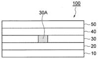
도 1은 본 발명의 일실시형태에 따른 편광판의 모식적인 단면도이다.
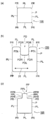
도 2의 (a)∼(c)는 본 발명의 일실시형태에 따른 편광판의 상면도이다.
도 3은 엔드 밀의 날끝 근방의 축에 수직인 단면도이다.1 is a schematic cross-sectional view of a polarizing plate according to an embodiment of the present invention.
2A to 2C are top views of a polarizing plate according to an embodiment of the present invention.
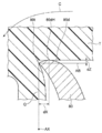
Fig. 3 is a cross-sectional view perpendicular to the axis in the vicinity of the blade tip of the end mill.
이하, 도면을 참조하면서, 본 발명의 적합한 실시형태에 대해서 설명한다. 도면에 있어서, 동등한 구성 요소에는 동등한 부호를 붙인다. 본 발명은 하기 실시형태에 한정되는 것이 아니다.EMBODIMENT OF THE INVENTION Hereinafter, preferred embodiment of this invention is described, referring drawings. In the drawings, equivalent components are denoted by equivalent reference numerals. The present invention is not limited to the following embodiments.
(편광판)(polarizer)
본 발명의 실시형태의 일례에 따른 편광판(100)의 단부면도를 도 1에 나타낸다. 본 실시형태에 따른 편광판(100)은, 제1 광학 수지 필름(10), 접착제층(20), 편광자층(30), 접착제층(40), 제2 광학 수지 필름(50)을 이 순서로 구비한다.The end view of the polarizing
편광자층(30)의 예는, 요오드, 2색성 염료 등의 2색성 색소에 의해 염색된 수지층이며, 연신되어 있어도 좋다. 이 수지층을 구성하는 수지는 소수성 수지여도 좋지만, 통상은 친수성 수지이다. 친수성 수지의 예는, 폴리비닐알코올계 수지, 폴리초산비닐 수지 및 에틸렌·초산비닐 공중합(EVA) 수지이다. 소수성 수지의 예는, 폴리아미드 수지 및 폴리에스테르계 수지이다. 편광자층(30)은, 염색 후에 붕산으로 처리되어도 좋다. 편광자층(30)의 전형예는, 폴리비닐알코올 필름에 요오드가 흡착 배향한 수지층이다. 편광자층인 수지층이 폴리비닐알코올계 수지 등의 친수성 수지로 구성되어 있는 경우에는, 외부와의 수분의 출입이 소수성 수지에 비해서 비교적 많고, 이것이 습열 환경에서의 색소 빠짐이나, 단부면에 있어서의 편광자층으로부터의 광학 수지 필름의 박리의 원인이 된다고 생각되는 바, 본 발명의 구성에 따르면, 이러한 색소 빠짐이나 박리를 억제할 수 있다.An example of the
편광자층(30)의 두께는, 예컨대, 2∼30 ㎛, 2∼15 ㎛, 또는 2∼10 ㎛여도 좋다.The thickness of the
제1 광학 수지 필름(10) 및 제2 광학 수지 필름(50)은 통상, 무색이며 투명한 수지 필름이다. 이러한 수지 필름의 예는, 보호 필름, 위상차 필름, 휘도 향상(반사형 편광자) 필름, 방현 필름, 표면 반사 방지 필름, 반사 필름, 반투과 반사 필름, 시야각 보상 필름, 광학 보상 필름, 터치 센서 필름, 대전 방지 필름 및 방오 필름이다.The 1st
각 광학 수지 필름을 구성하는 수지의 예는, 셀룰로오스계 수지(트리아세틸셀룰로오스 등), 폴리올레핀계 수지(폴리프로필렌계 수지 등), 환형 올레핀계 수지(노르보넨계 수지 등), 아크릴계 수지(폴리메틸메타크릴레이트계 수지 등), 또는, 폴리에스테르계 수지(폴리에틸렌테레프탈레이트계 수지 등)여도 좋다. 제1 광학 수지 필름(10) 및 제2 광학 수지 필름(50)은 다층막이어도 좋다.Examples of the resin constituting each optical resin film include a cellulose-based resin (triacetyl cellulose, etc.), a polyolefin-based resin (polypropylene-based resin, etc.), a cyclic olefin-based resin (norbornene-based resin, etc.), an acrylic resin (polymethyl methacrylate resin etc.) or polyester resin (polyethylene terephthalate resin etc.) may be sufficient. The first
제1 광학 수지 필름(10) 및 제2 광학 수지 필름(50)의 두께는, 예컨대, 5∼200 ㎛여도 좋다.The thickness of the 1st
제1 광학 수지 필름(10) 및 제2 광학 수지 필름(50)의 재료 및 두께는 서로 동일하여도 좋고, 서로 달라도 좋다.The material and thickness of the 1st
접착제층(20, 40)은, 편광자층(30)과 제1 광학 수지 필름(10) 또는 제2 광학 수지 필름(50)을 접착할 수 있는 투명 재료이면 재료에 특별한 한정은 없다. 접착제의 하나의 예는, 에폭시 수지이다. 에폭시 수지는, 예컨대, 수소화 에폭시 수지, 지환식 에폭시 수지, 또는 지방족 에폭시 수지여도 좋다. 중합 개시제(광양이온 중합 재시제, 열양이온 중합 개시제, 광라디칼 중합 개시제 또는 열라디칼 중합 개시제 등), 또는 다른 첨가제(증감제 등)를 에폭시 수지에 첨가하여도 좋다.The
접착제의 다른 예는, 아크릴아미드, 아크릴레이트, 우레탄아크릴레이트 및 에폭시아크릴레이트 등의 아크릴계 수지이다.Other examples of the adhesive are acrylic resins such as acrylamide, acrylate, urethane acrylate and epoxy acrylate.
접착제의 다른 예는, 폴리비닐알코올계 수지 등의 수계 접착제이다.Another example of the adhesive is a water-based adhesive such as polyvinyl alcohol-based resin.
접착제의 다른 예는, 감압성 접착제이다. 감압성 접착제의 예는, 아크릴계 수지, 실리콘계 수지, 폴리에스테르, 폴리우레탄, 또는 폴리에테르 등을 포함하는 감압형 접착제이다.Another example of an adhesive is a pressure-sensitive adhesive. Examples of the pressure-sensitive adhesive include a pressure-sensitive adhesive containing an acrylic resin, a silicone-based resin, polyester, polyurethane, or polyether.
편광자층(30)과 제1 광학 수지 필름(10)은 접착제층(20)만을 통해 적층되어 있어도 좋고, 편광자층(30)과 접착제층(20) 사이나, 접착제층(20)과 제1 광학 수지 필름(10) 사이에 이접착층(易接着層)(도시하지 않음)이 마련되어 있어도 좋다. 또한, 편광자층(30)과 제2 광학 수지 필름(50) 사이는 접착제층(40)만을 통해 적층되어 있어도 좋고, 편광자층(30)과 접착제층(40) 사이나, 접착제층(40)과 제2 광학 수지 필름(50) 사이에 이접착층(도시하지 않음)이 마려되어 있어도 좋다. 이접착층은, 접착제층(20, 40)과, 편광자층(30), 제1 광학 수지 필름(10) 또는 제2 광학 수지 필름(50) 사이의 접착력을 향상시킬 수 있는 것이다.The
접착제층(20)의 두께는, 예컨대, 0.01 ㎛∼5 ㎛, 0.05∼3 ㎛, 또는 0.1∼1 ㎛여도 좋다. 감압성 접착제를 이용하는 경우, 접착제층(20)의 두께는, 예컨대, 2∼500 ㎛, 2∼200 ㎛, 또는 2∼50 ㎛여도 좋다.The thickness of the
편광판(100)의 전체의 두께는, 예컨대, 10∼500 ㎛, 10∼300 ㎛, 또는 10∼200 ㎛여도 좋다.The overall thickness of the polarizing
제1 광학 수지 필름(10)의 아래, 또는, 제2 광학 수지 필름(50)의 위에, 감압성 접착제층(점착층) 및 세퍼레이터 필름을 더 마련하여도 좋다. 또한, 제1 광학 수지 필름(10)의 아래, 또는, 제2 광학 수지 필름(50)의 위에, 프로텍트 필름을 더 마련하여도 좋다.A pressure-sensitive adhesive layer (adhesive layer) and a separator film may be further provided under the first
세퍼레이터 필름은, 감압성 접착제층으로부터 박리 가능한 필름이며, 감압성 접착제층에의 이물의 부착을 방지하는 것이다. 예컨대, 편광판(100)을 화상 표시 소자에 접착하는 경우, 세퍼레이터 필름이 박리되어 감압식 접착제층이 노출된다. 세퍼레이터 필름을 구성하는 수지는, 예컨대, 폴리에틸렌계 수지, 폴리프로필렌계 수지, 또는 폴리에스테르계 수지(폴리에틸렌테레프탈레이트 등)여도 좋다.A separator film is a film which can be peeled from a pressure-sensitive adhesive bond layer, and prevents adhesion of the foreign material to a pressure-sensitive adhesive bond layer. For example, when the polarizing
프로텍트 필름은, 제1 광학 수지 필름(10) 또는 제2 광학 수지 필름(50)의 손상을 방지하기 위한 필름이며, 예컨대 자기 점착성의 수지 필름 단독이어도 좋고, 수지 필름과, 이 수지 필름에 적층된 감압성 접착제로 구성되는 다층 필름이어도 좋다. 프로텍트 필름은, 이것이 마련되는 제1 광학 수지 필름(10)이나 제2 광학 수지 필름(50)으로부터 박리 가능하다. 프로텍트 필름이 수지 필름에 감압성 접착제를 적층한 다층 필름인 경우에, 프로텍트 필름은, 그 감압성 접착제와 함께, 제1 광학 수지 필름(10) 또는 제2 광학 수지 필름(50)으로부터 박리된다. 프로텍트 필름의 수지도, 세퍼레이터 필름과 동일하게 할 수 있다.The protection film is a film for preventing damage to the first
세퍼레이터 필름 및 프로텍트 필름의 두께는, 예컨대, 2∼500 ㎛, 2∼200 ㎛, 또는 2∼100 ㎛여도 좋다.The thickness of the separator film and the protection film may be, for example, 2 to 500 µm, 2 to 200 µm, or 2 to 100 µm.
본 실시형태에 따른 편광판(100)은, 그 두께 방향에서 보아, 편광판(100)의 외주 가장자리(P)가 직선만으로 형성되는(예컨대 직사각형) 것이 아니라, 오목부, 볼록부 및 곡선부로 이루어지는 군에서 선택되는 적어도 하나를 갖는다.In the
예컨대, 도 2의 (a)에 나타내는 편광판(100)과 같이, 외주 가장자리(P)는, 이웃끼리 직교하는 4개의 직선부(PL)와, 2개의 직선부(PL) 사이에 각각 마련된 면취 곡선부(PR)를 가질 수 있다. 바꾸어 말하면, 이 편광판(100)의 외주 가장자리(P)는, 직사각형의 4개의 각부에 각각 면취 곡선부(PR)가 마려되어 있다.For example, like the
또한, 도 2의 (b)에 나타내는 편광판(100)과 같이, 도 2의 (a)의 편광판(100)의 외주 가장자리(P)의 하나의 직선부(PL)에 대하여, 오목부(PD)를 더 마련하여도 좋다. 오목부(PD)의 형상에 한정은 없지만, 예컨대, 도 2의 (b)에 나타내는 바와 같이, 이웃끼리 직교하는 3개의 직선부(PDL)를 갖는 대략 직사각형 형상이며, 직선부(PDL) 사이에 각각 면취 곡선부(PDR)를 가지고, 직선부(PDL)와 직선부(PL) 사이에 각각 면취 곡선부(PDR)를 갖는 형상일 수 있다. 2개의 직선부(PDL) 사이에 갖는 상기 곡선부(PDR)는, 편광판(100)의 면내를 향하여 오목형이다. 직선부(PDL)와 직선부(PL) 사이에 갖는 면취 곡선부(PDR)는, 편광판(100)의 면외를 향하여 볼록형으로 되어 있다.Moreover, like the
또한, 도 2의 (c)에 나타내는 편광판(100)과 같이, 도 2의 (a)의 편광판(100)의 외주 가장자리(P)의 하나의 직선부(PL)에 대하여, 볼록부(PP)가 마련되어 있어도 좋다. 볼록부(PP)의 형상에 한정은 없지만, 예컨대, 도 2의 (c)에 나타내는 바와 같이, 이웃끼리 직교하는 3개의 직선부(PPL)를 갖는 대략 직사각형 형상이며, 직선부(PPL) 사이에 각각 면취 곡선부(PPR)를 가지고, 직선부(PPL)와 직선부(PL) 사이에 각각 면취 곡선부(PPR)를 갖는 형상일 수 있다. 2개의 직선부(PPL) 사이에 갖는 면취 곡선부(PPR)는, 편광판(100)의 면내를 향하여 오목형으로 되어 있다. 직선부(PPL)와 직선부(PL) 사이에 갖는 면취 곡선부(PPR)는, 편광판(100)의 면외를 향하여 볼록형으로 되어 있다.Moreover, like the
오목부(PD)의 직선부(PL)로부터의 깊이 및 볼록부(PP)의 직선부(PL)로부터의 높이에 특별한 한정은 없지만, 전형적으로는 1.0 ㎜ 이상일 수 있다. 또한, 오목부(PD)의 폭 및 볼록부(PP)의 폭에도 특별한 한정은 없지만, 전형적으로는, 3.0 ㎜ 이상일 수 있다.There is no particular limitation on the depth of the concave portion PD from the straight portion PL and the height of the convex portion PP from the straight portion PL, but typically may be 1.0 mm or more. In addition, the width of the concave portion PD and the width of the convex portion PP are not particularly limited, but may typically be 3.0 mm or more.
오목부(PD) 및 볼록부(PP)의 형상은, 도 2의 (b) 및 (c)와 같이, 4개 각이 면취 곡선부에 의해 둥글게 된 직사각형에 한정되지 않고, 단순한 직사각형, 반원, 다각형 등이어도 좋다.The shape of the concave portion PD and the convex portion PP is not limited to a rectangle in which four angles are rounded by a chamfered curve portion, as shown in Figs. 2 (b) and (c), a simple rectangle, a semicircle, A polygonal shape etc. may be sufficient.
각 면취 곡선부의 곡선은, 원호, 타원호, 스플라인 곡선이어도 좋다. 각 면취 곡선부의 곡률 반경은 1.0∼40 ㎜로 할 수 있다.The curve of each chamfered curve portion may be a circular arc, an elliptical arc, or a spline curve. The radius of curvature of each chamfered curved portion can be 1.0 to 40 mm.
또한, 도 2의 (a)의 외주 가장자리(P)에 있어서, 4개의 면취 곡선부(PR) 중 1∼3개는, 면취 곡선이 아닌 단순한 각부여도 좋다. 도 2의 (b) 및 (c)의 외주 가장자리(P)에 있어서, 4개의 면취 곡선부(PR) 중 1∼4개는, 면취 곡선이 아닌 단순한 각부여도 좋다. 또한, 외주 가장자리(P)는, 도 2의 (a)∼(c)에 나타내는 바와 같은 직사각형을 베이스로 한 형태가 아니어도 좋고, 삼각형, 육각형 등, 다각형을 베이스로 한 형태여도 좋다.In addition, in the outer peripheral edge P of Fig.2 (a), 1-3 of four chamfering curve parts PR may not be a chamfering curve, but a simple angle part may be sufficient. In the outer peripheral edge P of Figs. 2(b) and (c), 1 to 4 of the four chamfered curve portions PR may be provided with a simple angle instead of a chamfered curve. In addition, the form based on the rectangle as shown to Fig.2 (a)-(c) may not be sufficient as the outer peripheral edge P, and the form based on polygons, such as a triangle and a hexagon, may be sufficient as it.
또한, 편광자층(30)의 흡수축은, 사용되는 화상 표시 장치 등에 따라, 편광판(100)의 임의의 방향을 향할 수 있다.In addition, the absorption axis of the
(산술 평균 높이(Sa))(arithmetic mean height (Sa))
도 1로 되돌아가서, 본 발명의 실시형태에 따른 편광판(100)에 있어서, 편광판(100)의 편광자층(30)의 단부면의 산술 평균 높이(Sa)는, 0.3∼0.7 ㎛이다. Sa는 0.4 ㎛ 이상이어도 좋고, 0.6 ㎛ 이하여도 좋다.Returning to FIG. 1, in the
편광자층(30)의 단부면의 산술 평균 높이(Sa)는, 단부면 상의 임의의 2차원 측정 영역(30A)에 있어서 이하와 같이 정의된다. 편광자층(30)의 단부면에 평행인 면을 XY면으로 하고, 단부면으로부터 수직인 높이 방향을 Z 방향으로 하고, 단부면의 2차원 측정 영역(30A)에 있어서의 평균 높이의 위치를 Z=0으로 한 XYZ 좌표계를 정의하고, 2차원 측정 영역(30A)의 각 x 좌표 및 각 y 좌표에 있어서의 높이를 Z(x, y)로 하였을 때에, 산술 평균 높이(Sa)는 아래 식으로 표시된다. 여기서, A는, 2차원 측정 영역(30A)의 면적이다.The arithmetic mean height Sa of the end surface of the

2차원 측정 영역(30A)에 있어서의 x, y마다의 높이(Z(x, y))는, 주사형 간섭 현미경, 원자간력 현미경 등에 의해 취득할 수 있다. 2차원 측정 영역(30A)의 크기는, 예컨대, 1변 5∼1000 ㎛의 직사각형 영역으로 할 수 있다.The height Z(x, y) for each x and y in the two-
(2승 평균 평방근 높이(Sq))(root mean square height (Sq))
또한, 편광자층(30)의 단부면의 2승 평균 평방근 높이(Sq)는 0.4∼0.8 ㎛일 수 있다. Sq는 0.5 ㎛ 이상이어도 좋고, 0.7 ㎛ 이하여도 좋다.In addition, the root mean square height (Sq) of the end surface of the
임의의 2차원 측정 영역(30A)에 있어서의 2승 평균 평방근 높이(Sq)는, 아래 식에 따라 정의된다.The root mean square height Sq in the arbitrary two-

(최대 높이(Sz))(maximum height (Sz))
또한, 편광자층(30)의 단부면의 최대 높이(Sz)는 5.0 ㎛ 이하일 수 있다. Sz는 4.0 ㎛ 이하여도 좋다.In addition, the maximum height Sz of the end surface of the
최대 높이(Sz)는, 2차원 측정 영역(30A)에 있어서의 최대 산높이와 최대 골깊이의 절대값의 합이다.The maximum height Sz is the sum of the absolute values of the maximum mountain height and the maximum valley depth in the two-
2차원 측정 영역(30A)에 있어서의 3차원 표면 거칠기의 측정은 ISO25178에 준거할 수 있다.The measurement of the three-dimensional surface roughness in the two-
여기서, 2차원 측정 영역(30A)은, 외주 가장자리(P)에 있어서의 어느 하나의 직선부, 즉, 단부면에 있어서의 평면부인 것이 바람직하고, 오목부(PD) 및 볼록부(PP) 내의 평면부여도 좋고, 오목부(PD) 및 볼록부(PP) 이외의 평면부, 예컨대 이웃끼리 직교하는 4개의 직선부(PL) 상의 평면부여도 좋다.Here, it is preferable that the two-dimensional measurement area|
후술하는 바와 같이, 외주 가장자리(P)가 직선부만으로 형성되는 편광판과 다르게, 오목부, 볼록부, 또는, 곡선부를 갖는 편광판의 단부면을 평면 연삭 장치로 절삭하여 치수 조정할 수는 없다. 따라서, 이러한 편광판의 단부면은, 통상, 외주의 전체에 걸쳐 엔드 밀로 절삭 처리된다. 그 때문에, 단부면의 어느 곳이라도 대체로 동일한 표면 거칠기를 갖는다.As will be described later, unlike a polarizing plate in which the outer peripheral edge P is formed only of a straight portion, the end face of the polarizing plate having a concave portion, a convex portion, or a curved portion cannot be cut by a plane grinding device to adjust the dimensions. Therefore, the end surface of such a polarizing plate is cut with an end mill over the whole outer periphery normally. Therefore, it has substantially the same surface roughness at any of the end faces.
외주 가장자리(P)에 있어서의 직선부, 즉, 단부면에 있어서의 평면부는, 평균 높이가 0이 되는 면이 평면이 되어, Z=0의 면을 결정하기 쉽기 때문에 2차원 측정 영역(30A)으로서 바람직하다.As for the straight part in the outer peripheral edge P, that is, the plane part in the end surface, the plane whose average height becomes 0 becomes a plane, and since it is easy to determine the plane of Z=0, the two-dimensional measurement area|
2차원 측정 영역(30A)은, 편광자층(30)의 흡수축(연신 방향) 방향의 단부에 있는 것도 바람직하다. 또한, 2차원 측정 영역(30A)이 흡수축 방향의 단부에 있으면, 이 영역(30A)는 편광자층(30)의 흡수축과 교차하게 된다.It is also preferable that the two-dimensional measurement area|
편광자층(30)의 단부면에 있어서의 산술 평균 높이(Sa)가 크면, 단부면의 표면적이 커지기 때문에, 습열 환경에 있어서의 색소 빠짐이 커지는 경향이 있다. 한편, 편광자층(30)의 단부면에 있어서의 산술 평균 높이(Sa)가 작으면, 편광자층(30)으로부터의 제1 광학 수지 필름(10) 및/또는 제2 광학 수지 필름(50)의 박리량이 커지기 쉬워지는 경향이 있다. 또한, Sa가 작은 상황은, 톰슨날로 펀칭한 채로, 단부면의 연마를 하지 않은 상태에 대응하는데, 펀칭의 충격에 기인하는 광학 수지 필름의 박리에 기인한다고 추찰된다.Since the surface area of an end surface becomes large when the arithmetic mean height Sa in the end surface of the
편광자층(30)의 단부면에 있어서의 2승 평균 평방근 높이(Sq)가 크면, 단부면의 표면적이 커지기 때문에, 습열 환경에 있어서의 색소 빠짐이 커지는 경향이 있다. 한편, 편광자층(30)의 단부면에 있어서의 2승 평균 평방근 높이(Sq)가 작으면, 편광자층(30)으로부터의 제1 광학 수지 필름(10) 및/또는 제2 광학 수지 필름(50)의 박리량이 커지기 쉬워지는 경향이 있다.Since the surface area of an end surface becomes large when the root mean square height Sq in the end surface of the
편광자층(30)의 단부면에 있어서의 최대 높이(Sz)가 크면, 단부면의 표면적이 커지기 때문에, 습열 환경에 있어서의 색소 빠짐이 커지는 경향이 있다.Since the surface area of an end surface becomes large when the maximum height Sz in the end surface of the
이러한 편광판은, 예컨대, 액정 셀이나 유기 EL 소자 등의 표시 패널에 접합하여, 액정 표시 장치 또는 유기 EL 표시 장치 등의 화상 표시 장치에 이용할 수 있다. 액정 표시 장치는, 예컨대, 액정 셀과, 액정 셀의 한쪽의 표면 또는 양 표면에 접착된 전술한 편광판을 포함하여도 좋다. 유기 EL 표시 장치는, 예컨대, 유기 EL 소자와, 유기 EL 소자의 표면에 접착된 전술한 편광판을 포함하여도 좋다. 액정 셀에는, 통상 2장의 편광판이 배치된다.Such a polarizing plate can be bonded to display panels, such as a liquid crystal cell and an organic electroluminescent element, for example, and can be utilized for image display apparatuses, such as a liquid crystal display device or an organic electroluminescent display device. The liquid crystal display device may include, for example, a liquid crystal cell and the aforementioned polarizing plate adhered to one or both surfaces of the liquid crystal cell. The organic EL display device may include, for example, an organic EL element and the above-described polarizing plate adhered to the surface of the organic EL element. In the liquid crystal cell, two polarizing plates are normally arrange|positioned.
(편광판의 제조 방법)(Manufacturing method of polarizing plate)
계속해서, 상기 편광판(100)의 제조 방법을 설명한다.Then, the manufacturing method of the said
먼저, 공지의 방법에 따라, 전술한 층구성을 갖는 편광판(100)의 원단을 제조한다. 계속해서, 원단 필름을 톰슨날 등의 날붙이로 펀칭하여, 외주 가장자리(P)가 오목부, 볼록부, 또는, 곡선부를 갖는 편광판을 얻는다. 여기서, 톰슨날에 의한 절단만으로는, 외주 가장자리(P)에 있어서 충분한 치수 정밀도를 확보하는 것은 곤란하기 때문에, 단부면의 연삭 공정을 행한다.First, according to a known method, the original fabric of the
외주 가장자리(P)가 오목부, 볼록부, 또는, 곡선부를 갖는 경우, 직사각형의 편광판의 단부면 연삭에 이용되는 것 같은 평면 연삭 장치, 즉, 복수의 바이트를 한쪽의 주면에 둘레 방향으로 배열하여 마련한 회전 원판을, 그 주면과 편광판의 단부면이 평행해지도록 편광판의 단부면에 접촉시켜 절삭하는 장치를 사용하여 단부면 전체를 연삭할 수 없기 때문에, 엔드 밀을 이용하여 편광판의 단부면 전체를 절삭 가공한다. 보다 구체적으로는, 엔드 밀의 축방향을 편광판의 두께 방향과 평행하게 하여, 편광판의 단부면을 따라 엔드 밀과 편광판을 상대 이동시킴으로써, 편광판의 단부면을 절삭하여, 원하는 치수에 맞춘다.When the outer peripheral edge P has a concave portion, a convex portion, or a curved portion, a plane grinding device such as that used for grinding the end surface of a rectangular polarizing plate, that is, a plurality of bites is arranged on one main surface in the circumferential direction Since it is impossible to grind the entire end face using a device that cuts the provided rotating disc in contact with the end face of the polarizing plate so that the main surface and the end face of the polarizing plate are parallel, the entire end face of the polarizing plate is cut using an end mill. cut processing. More specifically, by making the axial direction of the end mill parallel to the thickness direction of the polarizing plate and relatively moving the end mill and the polarizing plate along the end face of the polarizing plate, the end face of the polarizing plate is cut to fit a desired dimension.
여기서, 나선 형상의 날을 갖는 엔드 밀을 이용하는 것이 적합하고, 특히, 날의 단면 형상에 있어서, 도 3에 있어서의 dZ 및 dZ/dX가 작은 엔드 밀을 이용하는 것이 바람직하다.Here, it is suitable to use an end mill having a spiral blade, and in particular, in the cross-sectional shape of the blade, it is preferable to use an end mill having small dZ and dZ/dX in FIG. 3 .
여기서, 도 3은 엔드 밀의 축에 수직인 단면에 있어서의 날(80)의 선단의 단면도이며, 엔드 밀의 회전 방향이 C이다. 이 날(80)은, 날끝(80t)과, 날끝(80t)보다 뒤쪽의 면(80d)을 갖는다. 이 면(80d)은, 날끝(80t)에 의한 절삭 직후에 절삭물(T)과 접촉할 수 있다. 본 실시형태에서는, 날끝(80t)과 엔드 밀의 회전축(AX)을 연결하는 직선(Q)을 기준으로 하고, 날끝(80t)을 개시점으로 하여, 직선(Q)과 직교하며 또한 날끝(80t)을 통과하는 직선(AB)을 따라 이동하면서, 주사형 간섭 현미경에 의해, 직선(AB)을 기준으로 한 면(80d)의 높이의 프로파일을 측정한다. 그리고, 이 프로파일로부터 면(80d)의 높이의 최대값인 dZ[㎛]와, dZ를 부여하는 AB 방향의 날끝(80t)으로부터의 거리(dX)[㎛]를 구한다.Here, FIG. 3 is a cross-sectional view of the tip of the
이때에, dZ≤1.0 ㎛가 되고, dZ/dX≤4가 되는 날끝을 갖는 엔드 밀을 이용하는 것이 적합하다. 이에 의해, 편광자층(30)의 단부면(20e)에 있어서의 표면 거칠기를 전술한 범위로 하기 쉽다. 나선형의 날을 갖는 엔드 밀이라도, dZ>1.0 ㎛ 또는 dZ/dX>4가 되는 엔드 밀에서는, 표면 거칠기가 지나치게 커지는 경향이 있다.At this time, it is suitable to use an end mill having a cutting edge such that dZ≤1.0 µm and dZ/dX≤4. Thereby, it is easy to make the surface roughness in the end surface 20e of the
이상, 본 발명의 적합한 실시형태에 대해서 설명하였지만, 본 발명은 상기 실시형태에 하등 한정되는 것이 아니다.As mentioned above, although preferred embodiment of this invention was described, this invention is not limited at all to the said embodiment.
예컨대, 접착제층(20 및 40) 중 한쪽 또는 양쪽이 없어도 실시는 가능하다.For example, implementation is possible even without one or both of the
실시예Example
이하, 실시예 및 비교예를 들어 본 발명의 내용을 보다 구체적으로 설명한다. 또한, 본 발명은 하기 실시예에 한정되는 것이 아니다.Hereinafter, the content of the present invention will be described in more detail with reference to Examples and Comparative Examples. In addition, the present invention is not limited to the following examples.
[실시예 1][Example 1]
두께 20 ㎛의 폴리비닐알코올계 수지 필름을 연신하고, 요오드로 염색함으로써, 폴리비닐알코올계 수지에 요오드가 흡착 배향한 편광자(두께 8 ㎛)를 제작하였다. 이 편광자의 한쪽의 면에, 수계 접착제를 통해, 환형 올레핀계 수지(COP) 필름(닛폰제온 가부시키가이샤 제조, 두께 13 ㎛)을 접합하였다. 또한, COP 필름 상에, 박리 필름 상에 형성된 아크릴계 점착제층 A(두께 20 ㎛)를 적층하였다. 편광자의 다른쪽의 면에, 박리 필름 상에 형성된 아크릴계 점착제층 B(두께 5 ㎛)를 적층하였다. 박리 필름을 박리하여 노출된 아크릴계 점착제층 B 상에, 프로텍트 필름을 상면에 갖는 휘도 향상 필름(3M사 제조, APF-V3, 두께 30 ㎛, 반사형 편광자)을 접합하였다.A polarizer (8 µm in thickness) in which iodine was adsorbed and oriented to polyvinyl alcohol-based resin was produced by stretching a 20 µm-thick polyvinyl alcohol-based resin film and dyeing it with iodine. A cyclic olefin resin (COP) film (manufactured by Nippon Zeon Corporation, 13 µm in thickness) was bonded to one side of this polarizer via a water-based adhesive. Moreover, on the COP film, the acrylic adhesive layer A (20 micrometers in thickness) formed on the peeling film was laminated|stacked. On the other surface of the polarizer, the acrylic pressure-sensitive adhesive layer B (thickness of 5 µm) formed on the release film was laminated. A luminance enhancing film (manufactured by 3M, APF-V3, 30 µm thick, reflective polarizer) having a protection film on its upper surface was bonded onto the acrylic pressure-sensitive adhesive layer B exposed by peeling the release film.
이와 같이 하여, 박리 필름/아크릴계 점착제층 A/COP 필름/수계 접착제/편광자/아크릴계 점착제층 B/휘도 향상 필름/프로텍트 필름으로 이루어진 편광판의 원단을 제작하였다.In this way, the original fabric of the polarizing plate consisting of a release film/acrylic adhesive layer A/COP film/water-based adhesive agent/polarizer/acrylic adhesive layer B/brightness improvement film/protective film was produced.
원단으로부터, 톰슨날에 의해, 도 2의 (b)의 형상의 오목부(PD)를 갖는 편광판(100)을 절취하였다. 직사각형의 장변의 길이는 140 ㎜, 직사각형의 단변의 길이는 70 ㎜, 함몰의 깊이는 5 ㎜, 함몰의 폭은 30 ㎜, 면취 곡선부(PR)의 곡률 반경은 대략 10∼12 ㎜, 면취 곡선부(PDR)의 곡률 반경은 대략 3 ㎜로 하였다. 또한, 이 편광판(100)은, 하나의 오목부(PD)를 갖는다. 이 오목부(PD)는, 대략 직사각형이다. 이 오목부(PD)는, 이웃끼리 직교하는 3개의 직선부(PDL)를 갖는다. 직선부(PDL) 사이에는 각각 면취 곡선부(PDR)를 갖는다.The
직선부(PDL)와 직선부(PL) 사이에는 각각 면취 곡선부(PDR)를 갖는다. 이 편광판(100)의 흡수축(31)은, 오목부(PD)의 깊이 방향에 직교하고 있고, 도 2의 (b)에 있어서 좌우 방향이었다.A chamfered curved portion PDR is provided between the linear portion PDL and the linear portion PL, respectively. The
dZ가 평균으로 0.6 ㎛, dZ/dX가 평균으로 2.2인 나선 직경 형상의 날을 갖는 엔드 밀을 이용하여, 단부면의 전체 둘레를 연마하여 치수를 조정하여, 실시예 1의 편광판을 얻었다.Using an end mill having a helical diameter blade having an average dZ of 0.6 µm and an average dZ/dX of 2.2, the entire perimeter of the end face was polished to adjust the dimensions to obtain a polarizing plate of Example 1.
(비교예 1)(Comparative Example 1)
dZ가 평균으로 1.4 ㎛, dZ/dX가 평균으로 14인 나선 직경 형상의 날을 갖는 엔드 밀을 이용하여 단부면을 연마하는 것 이외에는, 실시예 1과 동일하게 하여 비교예 1의 편광판을 얻었다.A polarizing plate of Comparative Example 1 was obtained in the same manner as in Example 1, except that the end face was polished using an end mill having a helical diameter blade having an average of dZ of 1.4 µm and an average of dZ/dX of 14.
(비교예 2)(Comparative Example 2)
엔드 밀로 단부면을 연마하지 않고, 톰슨날로 절취한 채인 것 이외에는, 비교예 1과 동일하게 하여, 비교예 2의 편광판을 얻었다.The polarizing plate of the comparative example 2 was obtained like the comparative example 1 except having cut off with the Thomson blade, without grinding|polishing an end surface with an end mill.
(3차원 표면에 있어서의 거칠기(Sa, Sq, Sz)의 측정)(Measurement of roughness (Sa, Sq, Sz) on a three-dimensional surface)
편광자층의 단부면의 높이 함수(Z(x, y))를, 이하의 현미경에 의해 취득하였다.The height function (Z(x, y)) of the end surface of the polarizer layer was acquired with the following microscope.
주사형 백색 간섭 현미경 VS1000 시리즈 가부시키가이샤 히타치 하이테크 사이언스Scanning White Interference Microscope VS1000 Series Hitachi High-Tech Science Co., Ltd.
측정 조건: 대물 렌즈: 50×Measurement conditions: Objective lens: 50×
2차원 측정 영역: 편광판의 편광자층(PVA층)의 단부면의 직선부(흡수축과 직교하는 면)에 있어서의, 세로(두께 방향) 5∼8 ㎛×가로(두께 방향에 수직인 방향) 150∼300 ㎛Two-dimensional measurement area: 5 to 8 µm vertical (thickness direction) × horizontal (direction perpendicular to the thickness direction) in the straight portion (plane orthogonal to the absorption axis) of the end face of the polarizer layer (PVA layer) of the polarizing plate 150-300 μm
얻어진 함수(Z)에 기초하여, 상기 식에 기초하여, Sa, Sq 및 Sz를 각각 구하였다. Sa, Sq 및 Sz를 측정한 단부면은, 도 2의 (b)에 있어서의 좌우의 직선부(PL) 상에 위치하고, 흡수축(31)에 대하여 직교하고 있었다. 또한, 각 편광판(100)에 있어서의 Sa, Sq 및 Sz는, 전체 둘레에 걸쳐 동일한 값을 나타낸다.Based on the obtained function (Z), Sa, Sq, and Sz were respectively calculated|required based on the said formula. The end surfaces on which Sa, Sq, and Sz were measured were located on the left and right straight lines PL in FIG. 2B , and were orthogonal to the
(요오드 빠짐의 평가)(Evaluation of iodine depletion)
실시예 또는 비교예에서 얻은 편광판을, 65℃ 및 상대 습도 90%의 환경에 500시간 방치하였다.The polarizing plate obtained by the Example or the comparative example was left to stand in the environment of 65 degreeC and 90% of relative humidity for 500 hours.
그 후, 2장의 편광판(한쪽은 실시예 또는 비교예의 편광판, 다른쪽은 시판의 통상의 편광판)을 크로스 니콜에 배치하고, 광학 현미경을 이용하여 전체 둘레에 걸쳐 단부를 관찰하여, 크로스 니콜에 대응하는 감광이 발생하지 않은 영역(빛샘)의 단부로부터의 폭을 측정하였다. 이 빛샘은, 편광 성능을 발현하는 역할을 담당하는 요오드가 빠짐으로써 발생한다. 또한, 빛샘은, 도 2에 있어서의 오목부(PD)의 근방에서 발생하고 있고, 그 최대의 폭을 요오드 빠짐으로서 구하였다.Thereafter, two polarizing plates (one of the polarizing plates of Examples or Comparative Examples, the other of commercially available normal polarizing plates) are placed on the cross nicol, and the end is observed over the entire circumference using an optical microscope, corresponding to the cross nicol. The width from the end of the area (light leakage) in which the photosensitization did not occur was measured. This light leakage occurs when iodine, which plays a role in expressing the polarization performance, is omitted. In addition, light leakage has generate|occur|produced in the vicinity of the recessed part PD in FIG. 2, The largest width|variety was calculated|required as iodine loss|extraction.
(휘도 향상 필름의 박리량의 평가)(Evaluation of Peeling Amount of Brightness Improvement Film)
반사형 현미경에 의해 평가하였다.Evaluation was made by a reflection microscope.
조건 및 결과를 표 1에 나타낸다.The conditions and results are shown in Table 1.

실시예에서는, 요오드 빠짐량을 저감하면서 휘도 향상 필름의 박리량도 저감할 수 있었다.In the Example, the peeling amount of the brightness improvement film was also able to be reduced, reducing the amount of iodine loss.
본 발명에 따른 편광판은, 예컨대, 액정 셀 또는 유기 EL 소자 등에 접착되어, 액정 텔레비전, 유기 EL 텔레비전 또는 스마트 폰 등의 화상 표시 장치를 구성하는 광학 부품으로서 적용된다.The polarizing plate according to the present invention is adhered to, for example, a liquid crystal cell or an organic EL element, and is applied as an optical component constituting an image display device such as a liquid crystal television, an organic EL television, or a smart phone.
10…제1 광학 수지 필름, 30…편광자층, 50…제2 광학 수지 필름, P…외주 가장자리, PP…볼록부, PD…오목부, PR, PDR, PPR…면취 곡선부, 100…편광판.10… 1st optical resin film, 30... Polarizer layer, 50... 2nd optical resin film, P... Outer edge, PP... The convex part, PD... Concave, PR, PDR, PPR… Chamfered curved portion, 100 . . . polarizer.
Claims (4)
상기 편광판을 두께 방향에서 보아, 상기 편광판의 외주 가장자리의 형상은, 오목부, 볼록부 및 곡선부 중 적어도 하나를 가지고,
상기 편광자층의 단부면의 산술 평균 높이(Sa)가 0.3∼0.7 ㎛인 편광판.A polarizing plate comprising a polarizer layer, a first optical resin film provided on one surface of the polarizer layer, and a second optical resin film provided on the other surface of the polarizer layer,
When the polarizing plate is viewed in the thickness direction, the shape of the outer peripheral edge of the polarizing plate has at least one of a concave portion, a convex portion and a curved portion,
A polarizing plate having an arithmetic mean height (Sa) of 0.3 to 0.7 µm of an end surface of the polarizer layer.
상기 편광판을 두께 방향에서 보아, 상기 편광판의 외주 가장자리의 형상은, 오목부, 볼록부 및 곡선부 중 적어도 하나를 가지고,
상기 편광자층의 단부면의 2승 평균 평방근 높이(Sq)가 0.4∼0.8 ㎛인 편광판.A polarizing plate comprising a polarizer layer, a first optical resin film provided on one surface of the polarizer layer, and a second optical resin film provided on the other surface of the polarizer layer,
When the polarizing plate is viewed in the thickness direction, the shape of the outer peripheral edge of the polarizing plate has at least one of a concave portion, a convex portion and a curved portion,
A polarizing plate having a root mean square height (Sq) of 0.4 to 0.8 µm of an end surface of the polarizer layer.
Applications Claiming Priority (5)
| Application Number | Priority Date | Filing Date | Title |
|---|---|---|---|
| JP2019046826 | 2019-03-14 | ||
| JPJP-P-2019-046826 | 2019-03-14 | ||
| JP2019083239 | 2019-04-24 | ||
| JPJP-P-2019-083239 | 2019-04-24 | ||
| PCT/JP2020/005103 WO2020184030A1 (en) | 2019-03-14 | 2020-02-10 | Polarizing plate |
Publications (1)
| Publication Number | Publication Date |
|---|---|
| KR20210138567A true KR20210138567A (en) | 2021-11-19 |
Family
ID=72426399
Family Applications (1)
| Application Number | Title | Priority Date | Filing Date |
|---|---|---|---|
| KR1020217022112A KR20210138567A (en) | 2019-03-14 | 2020-02-10 | Polarizer |
Country Status (5)
| Country | Link |
|---|---|
| JP (2) | JP2020181184A (en) |
| KR (1) | KR20210138567A (en) |
| CN (1) | CN113574426B (en) |
| TW (1) | TWI842838B (en) |
| WO (1) | WO2020184030A1 (en) |
Families Citing this family (1)
| Publication number | Priority date | Publication date | Assignee | Title |
|---|---|---|---|---|
| JP7203879B2 (en) * | 2021-03-25 | 2023-01-13 | 日東電工株式会社 | Method for manufacturing polarizing plate and polarizing plate |
Citations (1)
| Publication number | Priority date | Publication date | Assignee | Title |
|---|---|---|---|---|
| JP2018092119A (en) | 2016-05-30 | 2018-06-14 | 住友化学株式会社 | Polarization plate, image display device and polarization plate manufacturing method |
Family Cites Families (24)
| Publication number | Priority date | Publication date | Assignee | Title |
|---|---|---|---|---|
| JP2000026817A (en) * | 1998-07-14 | 2000-01-25 | Teijin Ltd | Surface-protective film |
| JP4644661B2 (en) * | 2004-05-11 | 2011-03-02 | 日東電工株式会社 | Polarizing plate and image display device |
| JP4954662B2 (en) * | 2006-01-27 | 2012-06-20 | 日東電工株式会社 | Cutting method and manufacturing method of sheet-like member |
| WO2009008329A1 (en) * | 2007-07-06 | 2009-01-15 | Nitto Denko Corporation | Polarization plate |
| JP5525764B2 (en) * | 2009-06-15 | 2014-06-18 | 日東電工株式会社 | Release film, protective film for polarizing plate using the release film, and polarizing plate using protective film for the polarizing plate |
| JP2011020192A (en) * | 2009-07-14 | 2011-02-03 | Sumitomo Electric Hardmetal Corp | Spiral radius end mill |
| JP6172980B2 (en) | 2012-03-14 | 2017-08-02 | 日東電工株式会社 | Manufacturing method of liquid crystal display panel |
| JP6656799B2 (en) * | 2013-11-29 | 2020-03-04 | 王子ホールディングス株式会社 | Anti-Newton ring laminate and capacitive touch panel using the anti-Newton ring laminate |
| JP5979123B2 (en) * | 2013-12-05 | 2016-08-24 | 住友化学株式会社 | Polarizer with few bubble defects |
| JP6348291B2 (en) * | 2014-02-04 | 2018-06-27 | 住友化学株式会社 | Polarizing plate and display device |
| JP5886338B2 (en) * | 2014-02-21 | 2016-03-16 | 住友化学株式会社 | Polarizing plate, optical member set, and touch input type image display device |
| JP6258911B2 (en) | 2014-12-22 | 2018-01-10 | 住友化学株式会社 | Polarizing plate with protective film and laminate including the same |
| JP5976969B1 (en) * | 2015-06-19 | 2016-08-24 | 住友化学株式会社 | Manufacturing method of polarizing plate with protective film |
| WO2017047510A1 (en) * | 2015-09-16 | 2017-03-23 | シャープ株式会社 | Method for producing differently shaped polarizing plate |
| JP2017181597A (en) | 2016-03-28 | 2017-10-05 | 住友化学株式会社 | Optical film and polarizing plate |
| JP6684630B2 (en) * | 2016-03-31 | 2020-04-22 | 住友化学株式会社 | Polarizing plate and method of manufacturing polarizing plate |
| JP6899721B2 (en) * | 2016-07-22 | 2021-07-07 | 日東電工株式会社 | Polarizing plate manufacturing method and its manufacturing equipment |
| JP2018012182A (en) * | 2016-07-22 | 2018-01-25 | 日東電工株式会社 | Method and apparatus for manufacturing polarization plate |
| JP2018031954A (en) * | 2016-08-26 | 2018-03-01 | 日東電工株式会社 | Polarizing plate and method for manufacturing the same, and image display device using polarizing plate |
| JP6201025B1 (en) * | 2016-10-14 | 2017-09-20 | 住友化学株式会社 | Polarizer, polarizing plate and image display device |
| JP6306675B1 (en) * | 2016-11-28 | 2018-04-04 | 住友化学株式会社 | Method for producing polarizing laminated film with protective film and method for producing polarizing plate |
| KR102510750B1 (en) * | 2017-04-04 | 2023-03-15 | 스미또모 가가꾸 가부시키가이샤 | Polarizing plate with protective film, and liquid crystal panel |
| JP6634417B2 (en) * | 2017-07-20 | 2020-01-22 | 住友化学株式会社 | Manufacturing method of polarizing plate |
| JP6612294B2 (en) * | 2017-07-20 | 2019-11-27 | 住友化学株式会社 | Cutting device and method of manufacturing polarizing plate |
-
2020
- 2020-01-30 JP JP2020013914A patent/JP2020181184A/en active Pending
- 2020-02-10 CN CN202080020361.6A patent/CN113574426B/en active Active
- 2020-02-10 KR KR1020217022112A patent/KR20210138567A/en unknown
- 2020-02-10 WO PCT/JP2020/005103 patent/WO2020184030A1/en active Application Filing
- 2020-02-24 TW TW109105854A patent/TWI842838B/en active
- 2020-12-10 JP JP2020205110A patent/JP7284141B2/en active Active
Patent Citations (1)
| Publication number | Priority date | Publication date | Assignee | Title |
|---|---|---|---|---|
| JP2018092119A (en) | 2016-05-30 | 2018-06-14 | 住友化学株式会社 | Polarization plate, image display device and polarization plate manufacturing method |
Also Published As
| Publication number | Publication date |
|---|---|
| CN113574426B (en) | 2024-03-15 |
| WO2020184030A1 (en) | 2020-09-17 |
| TW202041897A (en) | 2020-11-16 |
| JP7284141B2 (en) | 2023-05-30 |
| JP2020181184A (en) | 2020-11-05 |
| JP2021047453A (en) | 2021-03-25 |
| CN113574426A (en) | 2021-10-29 |
| TWI842838B (en) | 2024-05-21 |
Similar Documents
| Publication | Publication Date | Title |
|---|---|---|
| KR102410190B1 (en) | Polarizers, polarizers and image display devices | |
| KR101199277B1 (en) | Cutting method and manufacturing method of sheet-like member, sheet-like member, optical element and image display device | |
| KR20190027773A (en) | Polarizing plate manufacturing method and apparatus | |
| KR101743884B1 (en) | Polarizing plate with adhesive, and image display device | |
| US11022735B2 (en) | Method of producing polarizing plate | |
| KR101810367B1 (en) | Polarizing plate and liquid crystal display device | |
| US10914868B2 (en) | Polarizing plate | |
| KR20220057594A (en) | Method of manufacturing a polarizing plate | |
| KR20210138567A (en) | Polarizer | |
| JP2021062448A (en) | Method of manufacturing optical member | |
| JP2012048181A (en) | Polarizer and liquid crystal display device using the same | |
| KR20210005860A (en) | Optical laminated body, optical laminated body with cover glass, and manufacturing method thereof, and image display device with cover glass | |
| JP6755223B2 (en) | Polarizer, polarizing plate and image display device | |
| JP7221256B2 (en) | A polarizing plate, a polarizing plate with a retardation layer, and an image display device comprising the polarizing plate or the polarizing plate with the retardation layer | |
| JP2021062447A (en) | Method of manufacturing optical member | |
| JP2003043262A (en) | Method for manufacturing laminated optical film | |
| KR102256908B1 (en) | Method for manufacturing polarization plate sheet | |
| JP7018272B2 (en) | Polarizing plate and liquid crystal display device |
Legal Events
| Date | Code | Title | Description |
|---|---|---|---|
| PA0105 | International application |
Patent event date: 20210714 Patent event code: PA01051R01D Comment text: International Patent Application |
|
| PG1501 | Laying open of application | ||
| PE0902 | Notice of grounds for rejection |
Comment text: Notification of reason for refusal Patent event date: 20250206 Patent event code: PE09021S01D |