JP2020181184A - Polarizer - Google Patents
Polarizer Download PDFInfo
- Publication number
- JP2020181184A JP2020181184A JP2020013914A JP2020013914A JP2020181184A JP 2020181184 A JP2020181184 A JP 2020181184A JP 2020013914 A JP2020013914 A JP 2020013914A JP 2020013914 A JP2020013914 A JP 2020013914A JP 2020181184 A JP2020181184 A JP 2020181184A
- Authority
- JP
- Japan
- Prior art keywords
- polarizing plate
- face
- polarizer
- resin film
- layer
- Prior art date
- Legal status (The legal status is an assumption and is not a legal conclusion. Google has not performed a legal analysis and makes no representation as to the accuracy of the status listed.)
- Pending
Links
Images
Classifications
-
- G—PHYSICS
- G02—OPTICS
- G02B—OPTICAL ELEMENTS, SYSTEMS OR APPARATUS
- G02B5/00—Optical elements other than lenses
- G02B5/30—Polarising elements
- G02B5/3025—Polarisers, i.e. arrangements capable of producing a definite output polarisation state from an unpolarised input state
- G02B5/3033—Polarisers, i.e. arrangements capable of producing a definite output polarisation state from an unpolarised input state in the form of a thin sheet or foil, e.g. Polaroid
-
- B—PERFORMING OPERATIONS; TRANSPORTING
- B32—LAYERED PRODUCTS
- B32B—LAYERED PRODUCTS, i.e. PRODUCTS BUILT-UP OF STRATA OF FLAT OR NON-FLAT, e.g. CELLULAR OR HONEYCOMB, FORM
- B32B7/00—Layered products characterised by the relation between layers; Layered products characterised by the relative orientation of features between layers, or by the relative values of a measurable parameter between layers, i.e. products comprising layers having different physical, chemical or physicochemical properties; Layered products characterised by the interconnection of layers
- B32B7/02—Physical, chemical or physicochemical properties
- B32B7/023—Optical properties
-
- G—PHYSICS
- G02—OPTICS
- G02B—OPTICAL ELEMENTS, SYSTEMS OR APPARATUS
- G02B1/00—Optical elements characterised by the material of which they are made; Optical coatings for optical elements
- G02B1/10—Optical coatings produced by application to, or surface treatment of, optical elements
- G02B1/14—Protective coatings, e.g. hard coatings
-
- G—PHYSICS
- G02—OPTICS
- G02B—OPTICAL ELEMENTS, SYSTEMS OR APPARATUS
- G02B5/00—Optical elements other than lenses
- G02B5/30—Polarising elements
Abstract
Description
本発明は、偏光板に関する。 The present invention relates to a polarizing plate.
偏光板は、通常、色素を含む偏光子層と、偏光子層の両側に設けられた一対の光学樹脂フィルムとを含み、液晶セル又は有機EL素子等の表示パネルに貼合して用いられる。偏光板の外周は通常、表示パネルの表示部の外周縁に合せた形状となっている。 The polarizing plate usually includes a polarizing element layer containing a dye and a pair of optical resin films provided on both sides of the polarizing element layer, and is used by being bonded to a display panel such as a liquid crystal cell or an organic EL element. The outer circumference of the polarizing plate is usually shaped to match the outer peripheral edge of the display portion of the display panel.
表示パネルの表示部の外周縁が平面視において、矩形形状でなく、凹部、凸部、及び曲線部のうちの少なくとも一つを有する場合、この表示部に使用される偏光板の外周縁もこれに対応して、矩形形状でなく、凹部、凸部、及び曲線部のうちの少なくとも一つを有する(例えば、特許文献1参照。)。 When the outer peripheral edge of the display portion of the display panel is not rectangular in plan view and has at least one of a concave portion, a convex portion, and a curved portion, the outer peripheral edge of the polarizing plate used for this display portion is also this. Corresponding to, it has at least one of a concave portion, a convex portion, and a curved portion instead of a rectangular shape (see, for example, Patent Document 1).
本発明者らが検討したところ、外周縁が、矩形形状でなく、凹部、凸部、及び曲線部のうちの少なくとも一つを有する偏光板では、外周縁が矩形の偏光板に比べて、湿熱環境で偏光子層から色素抜けが起こりやすかったり、端面において光学樹脂フィルムが偏光子から剥がれやすかったりすることが判明した。このような現象は、直線部よりも、凹部、凸部および曲線部や、その近傍に現れ易い。 As examined by the present inventors, in a polarizing plate having an outer peripheral edge not having a rectangular shape but having at least one of a concave portion, a convex portion, and a curved portion, a polarizing plate having a rectangular outer peripheral edge is more moist heat than a polarizing plate having a rectangular outer peripheral edge. It has been found that the dye is easily removed from the polarizing element layer in the environment, and the optical resin film is easily peeled off from the polarizer at the end face. Such a phenomenon is more likely to appear in the concave portion, the convex portion, the curved portion, and the vicinity thereof than in the straight portion.
本発明は、上記事情に鑑みてなされたものであり、外周縁が、凹部、凸部、及び曲線部のうちの少なくとも一つを有する偏光板において、湿熱環境での色素抜けが起こりにくく、かつ、端面において偏光子層からの光学樹脂フィルムの剥がれにくい偏光板を提供することを目的とする。 The present invention has been made in view of the above circumstances, and in a polarizing plate having an outer peripheral edge having at least one of a concave portion, a convex portion, and a curved portion, dye loss is unlikely to occur in a moist heat environment, and An object of the present invention is to provide a polarizing plate in which the optical resin film does not easily peel off from the polarizing element layer on the end face.
本発明に係る偏光板は、偏光子層と、前記偏光子層の一方の表面に設けられた第一光学樹脂フィルムと、前記偏光子層の他方の表面に設けられた第二光学樹脂フィルムと、を備える。そして、前記偏光板を厚み方向から見て、前記偏光板の外周縁の形状は、凹部、凸部、及び曲線部のうちの少なくとも一つを有し、前記偏光子層の端面の算術平均高さSaが0.3〜0.7μmである。 The polarizing plate according to the present invention includes a polarizing element layer, a first optical resin film provided on one surface of the polarizer layer, and a second optical resin film provided on the other surface of the polarizer layer. , Equipped with. When the polarizing plate is viewed from the thickness direction, the shape of the outer peripheral edge of the polarizing plate has at least one of a concave portion, a convex portion, and a curved portion, and the arithmetic mean height of the end face of the polarizing element layer. Sa is 0.3 to 0.7 μm.
また、本発明に係る別の偏光板は、偏光子層と、前記偏光子層の一方の表面に設けられた第一光学樹脂フィルムと、前記偏光子層の他方の面に設けられた第二光学樹脂フィルムと、を備える。そして、前記偏光子層の端面の2乗平均平方根高さSqが0.4〜0.8μmである。前記端面の算術平均高さSaは0.3〜0.7μmであることができる。 Further, another polarizing plate according to the present invention includes a polarizing element layer, a first optical resin film provided on one surface of the polarizer layer, and a second polarizing plate provided on the other surface of the polarizer layer. It includes an optical resin film. The root mean square height Sq of the end face of the polarizer layer is 0.4 to 0.8 μm. The arithmetic mean height Sa of the end face can be 0.3 to 0.7 μm.
本発明の偏光板は、前記偏光子層の端面の最大高さSzが5.0μm以下であることができる。 The polarizing plate of the present invention can have a maximum height Sz of the end face of the polarizer layer of 5.0 μm or less.
本発明によれば、外周縁が、凹部、凸部、及び曲線部のうちの少なくとも一つを有する偏光板において、湿熱環境での色素抜けが起こりにくく、かつ、端面において偏光子層からの光学樹脂フィルムの剥がれにくい偏光板が提供される。 According to the present invention, in a polarizing plate having an outer peripheral edge having at least one of a concave portion, a convex portion, and a curved portion, pigment loss is unlikely to occur in a moist heat environment, and optics from the polarizer layer at the end face. A polarizing plate that prevents the resin film from peeling off is provided.
以下、図面を参照しながら、本発明の好適な実施形態について説明する。図面において、同等の構成要素には同等の符号を付す。本発明は下記実施形態に限定されるものではない。 Hereinafter, preferred embodiments of the present invention will be described with reference to the drawings. In the drawings, equivalent components are designated by the same reference numerals. The present invention is not limited to the following embodiments.
(偏光板)
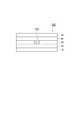
本発明の実施形態の一例に係る偏光板100の端面図を図1に示す。本実施形態に係る偏光板100は、第一光学樹脂フィルム10、接着剤層20、偏光子層30、接着剤層40、第二光学樹脂フィルム50をこの順に備える。
(Polarizer)
FIG. 1 shows an end view of the polarizing
偏光子層30の例は、ヨウ素、二色性染料などの二色性色素によって染色された樹脂層であり、延伸されていてもよい。この樹脂層を構成する樹脂は疎水性樹脂であってもよいが、通常は親水性樹脂である。親水性樹脂の例は、ポリビニルアルコール系樹脂、ポリ酢酸ビニル樹脂およびエチレン・酢酸ビニル共重合樹脂(EVA)樹脂である。疎水性樹脂の例は、ポリアミド樹脂、及び、ポリエステル系樹脂である。偏光子層30は、染色後にホウ酸で処理されてよい。偏光子層30の典型例は、ポリビニルアルコールフィルムにヨウ素が吸着配向した樹脂層である。偏光子層である樹脂層がポリビニルアルコール系樹脂などの親水性樹脂で構成されている場合には、外部との水分の出入りが疎水性樹脂に比べて比較的多く、これが湿熱環境での色素抜けや、端面における偏光子層からの光学樹脂フィルムの剥がれの原因となると考えられるところ、本発明の構成によれば、このような色素抜けや剥がれを抑制することができる。
An example of the
偏光子層30の厚さは、例えば、2〜30μm、2〜15μm、又は2〜10μmであってよい。
The thickness of the
第一光学樹脂フィルム10及び第二光学樹脂フィルム50は通常、無色で透明な樹脂フィルムである。このような樹脂フィルムの例は、保護フィルム、位相差フィルム、輝度向上(反射型偏光子)フィルム、防眩フィルム、表面反射防止フィルム、反射フィルム、半透過反射フィルム、視野角補償フィルム、光学補償フィルム、タッチセンサーフィルム、帯電防止フィルムおよび防汚フィルムである。
The first
各光学樹脂フィルムを構成する樹脂の例は、セルロース系樹脂(トリアセチルセルロース等)、ポリオレフィン系樹脂(ポリプロピレン系樹脂等)、環状オレフィン系樹脂(ノルボルネン系樹脂等)、アクリル系樹脂(ポリメチルメタクリレート系樹脂等)、又は、ポリエステル系樹脂(ポリエチレンテレフタレート系樹脂等)であってよい。第一光学樹脂フィルム10及び第二光学樹脂フィルム50は多層膜であってもよい。
Examples of resins constituting each optical resin film are cellulose-based resin (triacetyl cellulose, etc.), polyolefin-based resin (polypropylene-based resin, etc.), cyclic olefin-based resin (norbornen-based resin, etc.), acrylic resin (polymethyl methacrylate, etc.). It may be a based resin, etc.) or a polyester resin (polyethylene terephthalate resin, etc.). The first
第一光学樹脂フィルム10及び第二光学樹脂フィルム50の厚みは、例えば、5〜200μmであってよい。
The thickness of the first
第一光学樹脂フィルム10及び第二光学樹脂フィルム50の材料及び厚みは互いに同一であってもよく、互いに異なってもよい。
The materials and thicknesses of the first
接着剤層20、40は、偏光子層30と第一光学樹脂フィルム10又は第二光学樹脂フィルム50とを接着できる透明材料であれば材料に特段の限定はない。接着剤の一つの例は、エポキシ樹脂である。エポキシ樹脂は、例えば、水素化エポキシ樹脂、脂環式エポキシ樹脂、又は脂肪族エポキシ樹脂であってよい。重合開始剤(光カチオン重合開始剤、熱カチオン重合開始剤、光ラジカル重合開始剤又は熱ラジカル重合開始剤等)、又は他の添加剤(増感剤等)をエポキシ樹脂に添加してもよい。
The
接着剤の他の例は、アクリルアミド、アクリレート、ウレタンアクリレート、及びエポキシアクリレート等のアクリル系樹脂である。 Other examples of adhesives are acrylic resins such as acrylamide, acrylates, urethane acrylates, and epoxy acrylates.
接着剤の他の例は、ポリビニルアルコール系樹脂などの水系接着剤である。 Another example of the adhesive is a water-based adhesive such as a polyvinyl alcohol-based resin.
接着剤の他の例は、感圧性接着剤である。感圧性接着剤の例は、アクリル系樹脂、シリコーン系樹脂、ポリエステル、ポリウレタン、又はポリエーテル等を含む感圧型接着剤である。
偏光子層30と第一光学樹脂フィルム10とは接着剤層20のみを介して積層されていてもよいし、偏光子層30と接着剤層20との間や、接着剤層20と第一光学樹脂フィルム10との間に易接着層(図示せず)が設けられていてもよい。また、偏光子層30と第二光学樹脂フィルム50との間は接着剤層40のみを介して積層されていてもよいし、偏光子層30と接着剤層40との間や、接着剤層40と第二光学樹脂フィルム50との間に易接着層(図示せず)が設けられていてもよい。易接着層は、接着剤層20、40と、偏光子層30、第一光学樹脂フィルム10または第二光学樹脂フィルム50との間の接着力を向上させ得るものである。
Another example of an adhesive is a pressure sensitive adhesive. An example of a pressure-sensitive adhesive is a pressure-sensitive adhesive containing an acrylic resin, a silicone-based resin, polyester, polyurethane, a polyether, or the like.
The
接着剤層20の厚さは、例えば、0.01μm〜5μm、0.05〜3μm、又は0.1〜1μmであってよい。感圧性接着剤を用いる場合、接着剤層20の厚さは、例えば、2〜500μm、2〜200μm、又は2〜50μmであってよい。
The thickness of the
偏光板100の全体の厚さは、例えば、10〜500μm、10〜300μm、又は10〜200μmであってよい。
The total thickness of the polarizing
第一光学樹脂フィルム10の下、又は、第二光学樹脂フィルム50の上にさらに、感圧性接着剤層(粘着層)及びセパレータフィルムを設けてもよい。また、第一光学樹脂フィルム10の下、又は、第二光学樹脂フィルム50の上にさらに、プロテクトフィルムを設けてもよい。
A pressure-sensitive adhesive layer (adhesive layer) and a separator film may be further provided under the first
セパレータフィルムは、感圧性接着剤層から剥離可能なフィルムであり、感圧性接着剤層への異物の付着を防止するものである。例えば、偏光板100を画像表示素子に貼着する場合、セパレータフィルムが剥がされて感圧式接着剤層が露出される。セパレータフィルムを構成する樹脂は、例えば、ポリエチレン系樹脂、ポリプロピレン系樹脂、又はポリエステル系樹(ポリエチレンテレフタレート等)であってよい。
プロテクトフィルムは、第一光学樹脂フィルム10または第二光学樹脂フィルム50の傷付きを防止するためのフィルムであり、例えば自己粘着性の樹脂フィルム単独であってもよいし、樹脂フィルムと、この樹脂フィルムに積層された感圧性接着剤とで構成される多層フィルムであってもよい。プロテクトフィルムは、これが設けられる第一光学樹脂フィルム10や第二光学樹脂フィルム50から剥離可能である。プロテクトフィルムが樹脂フィルムに感圧性接着剤を積層した多層フィルムである場合に、プロテクトフィルムは、その感圧性接着剤ごと、第一光学樹脂フィルム10または第二光学樹脂フィルム50から剥離される。プロテクトフィルムの樹脂も、セパレータフィルムと同様とすることができる。
The separator film is a film that can be peeled off from the pressure-sensitive adhesive layer, and prevents foreign matter from adhering to the pressure-sensitive adhesive layer. For example, when the
The protective film is a film for preventing the first
セパレータフィルム及びプロテクトフィルムの厚さは、例えば、2〜500μm、2〜200μm、又は2〜100μmであってよい。 The thickness of the separator film and the protect film may be, for example, 2 to 500 μm, 2 to 200 μm, or 2 to 100 μm.
本実施形態に係る偏光板100は、その厚み方向から見て、偏光板100の外周縁Pが直線のみから形成される(例えば矩形)のではなく、凹部、凸部、及び、曲線部からなる群から選択される少なくとも一つを有する。
When viewed from the thickness direction of the
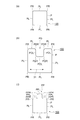
例えば、図2の(a)に示す偏光板100のように、外周縁Pは、隣同士で直交する4つの直線部PLと、2つの直線部PL間にそれぞれ設けられた面取り曲線部PRを有することができる。言い換えると、この偏光板100の外周縁Pは、矩形の4つの角部にそれぞれ面取り曲線部PRが設けられている。
For example, as in the
また、図2の(b)で示す偏光板100のように、図2の(a)の偏光板100の外周縁Pの一つの直線部PLに対して、さらに凹部PDを設けてもよい。凹部PDの形状に限定はないが、例えば、図2の(b)に示すように、隣同士で直交する3つの直線部PDLを有する略矩形形状で有り、直線部PDL間にそれぞれ面取り曲線部PDRを有し、直線部PDLと直線部PLとの間にそれぞれ面取り曲線部PDRを有する形状であることができる。2つの直線部PDL間に有する上記曲線部PDRは、偏光板100の面内に向けて凹形状である。直線部PDLと直線部PLとの間に有する面取り曲線部PDRは、偏光板100の面外に向けて凸形状となっている。
Further, as in the
また、図2の(c)で示す偏光板100のように、図2の(a)の偏光板100の外周縁Pの一つの直線部PLに対して、凸部PPが設けられていてもよい。凸部PPの形状に限定はないが、例えば、図2の(c)に示すように、隣同士で直交する3つの直線部PPLを有する略矩形形状で有り、直線部PPL間にそれぞれ面取り曲線部PPRを有し、直線部PPLと直線部PLとの間にそれぞれ面取り曲線部PPRを有する形状であることができる。2つの直線部PPL間に有する面取り曲線部PPRは、偏光板100の面内に向けて凹形状となっている。直線部PPLと直線部PLとの間に有する面取り曲線部PPRは、偏光板100の面外に向けて凸形状となっている。
Further, as in the
凹部PDの直線部PLからの深さ、及び、凸部PPの直線部PLからの高さに特段の限定はないが、典型的には1.0mm以上であることができる。また、凹部PDの幅、及び、凸部PPの幅にも特段の限定はないが、典型的には、3.0mm以上であることができる。 The depth of the concave portion PD from the straight portion PL and the height of the convex portion PP from the straight portion PL are not particularly limited, but can typically be 1.0 mm or more. Further, the width of the concave portion PD and the width of the convex portion PP are not particularly limited, but can typically be 3.0 mm or more.
凹部PD及び凸部PPの形状は、図2の(b)及び(c)のように、4つ角が面取り曲線部により丸くされた矩形に限定されず、単なる矩形、半円、多角形等でもよい。 The shapes of the concave PD and the convex PP are not limited to rectangles having four corners rounded by chamfered curved portions as shown in FIGS. 2 (b) and 2 (c), but are simply rectangles, semicircles, polygons, etc. It may be.
各面取り曲線部の曲線は、円弧、楕円弧、スプライン曲線であってもよい。各面取り曲線部の曲率半径は1.0〜40mmとすることができる。 The curve of each chamfered curve portion may be an arc, an elliptical arc, or a spline curve. The radius of curvature of each chamfered curved portion can be 1.0 to 40 mm.
また、図2の(a)の外周縁Pにおいて、4つの面取り曲線部PRのうちの1〜3つは、面取り曲線でない単なる角部でもよい。図2の(b)及び(c)の外周縁Pにおいて、4つの面取り曲線部PRのうちの1〜4つは、面取り曲線でない単なる角部でもよい。さらに、外周縁Pは、図2の(a)〜(c)に示すような矩形をベースとした形態でなくてもよく、三角形、六角形など、多角形をベースとした形態でもよい。 Further, in the outer peripheral edge P of FIG. 2A, 1 to 3 of the four chamfered curve portions PR may be simple corner portions that are not chamfered curves. In the outer peripheral edge P of FIGS. 2B and 2C, 1 to 4 of the four chamfered curved portions PR may be simple corner portions that are not chamfered curves. Further, the outer peripheral edge P does not have to be a rectangular-based form as shown in FIGS. 2A to 2C, but may be a polygon-based form such as a triangle or a hexagon.
また、偏光子層30の吸収軸は、使用される画像表示装置等に応じて、偏光板100の任意の方向を向くことができる。
Further, the absorption axis of the
(算術平均高さSa)
図1に戻って、本発明の実施形態に係る偏光板100において、偏光板100の偏光子層30の端面の算術平均高さSaは、0.3〜0.7μmである。Saは0.4μm以上でもよく、0.6μm以下でもよい。
(Arithmetic mean height Sa)
Returning to FIG. 1, in the
偏光子層30の端面の算術平均高さSaは、端面上の任意の2次元測定領域30Aにおいて以下のように定義される。偏光子層30の端面に平行な面をXY面とし、端面から垂直な高さ方向をZ方向とし、端面の2次元測定領域30Aにおける平均高さの位置をZ=0としたXYZ座標系を定義し、2次元測定領域30Aの各x座標及び各y座標における高さをZ(x,y)としたときに、算術平均高さSaは下式で表される。ここで、Aは、2次元測定領域30Aの面積である。
The arithmetic mean height Sa of the end face of the
![]()
![]()
2次元測定領域30Aにおけるx、y毎の高さZ(x,y)は、走査型干渉顕微鏡、原子間力顕微鏡などにより取得できる。2次元測定領域30Aの大きさは、例えば、一辺5〜1000μmの矩形領域とすることができる。
The height Z (x, y) for each x, y in the two-
(2乗平均平方根高さSq)
また、偏光子層30の端面の2乗平均平方根高さSqは0.4〜0.8μmであることができる。Sqは0.5μm以上であってもよく、0.7μm以下であってもよい。
(Root mean square height Sq)
Further, the root mean square height Sq of the end face of the
任意の2次元測定領域30Aにおける2乗平均平方根高さSqは、下式により定義される。

(最大高さSz)
また、偏光子層30の端面の最大高さSzは5.0μm以下であることができる。Szは4.0μm以下でもよい。
(Maximum height Sz)
Further, the maximum height Sz of the end face of the
最大高さSzは、2次元測定領域30Aにおける最大山高さと最大谷深さの絶対値との和である。
The maximum height Sz is the sum of the maximum peak height and the absolute value of the maximum valley depth in the two-
2次元測定領域30Aにおける3次元表面粗さの測定はISO25178に準拠することが出来る。
The measurement of the three-dimensional surface roughness in the two-
ここで、2次元測定領域30Aは、外周縁Pにおけるいずれかの直線部、すなわち、端面における平面部であることが好ましく、凹部PD、及び、凸部PP内の平面部であってもよいし、凹部PD及び凸部PP以外の平面部、例えば隣同士で直交する4つの直線部PL上の平面部であってもよい。
Here, the two-
後述するように、外周縁Pが直線部のみから形成される偏光板と異なり、凹部、凸部、又は、曲線部を有する偏光板の端面を平面研削装置で切削して寸法調整することはできない。したがって、このような偏光板の端面は、通常、外周の全体にわたってエンドミルで切削処理される。そのため、端面のいずれの場所であってもおおむね同様の表面粗さを有する。
外周縁Pにおける直線部、すなわち、端面における平面部は、平均高さが0となる面が平面となり、Z=0の面を決めやすいので2次元測定領域30Aとして好ましい。
As will be described later, unlike a polarizing plate in which the outer peripheral edge P is formed only from a straight portion, the end face of a polarizing plate having a concave portion, a convex portion, or a curved portion cannot be cut by a surface grinding device to adjust the dimensions. .. Therefore, the end face of such a polarizing plate is usually cut by an end mill over the entire outer circumference. Therefore, it has almost the same surface roughness at any place on the end face.
The straight portion on the outer peripheral edge P, that is, the flat portion on the end surface is preferable as the two-
2次元測定領域30Aは、偏光子層30の吸収軸(延伸方向)方向の端部にあることも好ましい。なお、2次元測定領域30Aが吸収軸方向の端部にあると、この領域30Aは偏光子層30の吸収軸と交わることとなる。
It is also preferable that the two-
偏光子層30の端面における算術平均高さSaが大きいと、端面の表面積が大きくなるため、湿熱環境における色素抜けが大きくなる傾向がある。一方、偏光子層30の端面における算術平均高さSaが小さいと、偏光子層30からの第一光学樹脂フィルム10及び/又は第二光学樹脂フィルム50の剥離量が大きくなりやすくなる傾向がある。なお、Saが小さい状況は、トムソン刃で打ち抜いたまま、端面の研磨をしていない状態に対応するが、打ち抜きの衝撃に起因する光学樹脂フィルムの剥がれに起因すると推察される。
When the arithmetic mean height Sa on the end face of the
偏光子層30の端面における2乗平均平方根高さSqが大きいと、端面の表面積が大きくなるため、湿熱環境における色素素抜けが大きくなる傾向がある。一方、偏光子層30の端面における2乗平均平方根高さSqが小さいと、偏光子層30からの第一光学樹脂フィルム10及び/又は第二光学樹脂フィルム50の剥離量が大きくなりやすくなる傾向がある。
When the root mean square height Sq of the end face of the
偏光子層30の端面における最大高さSzが大きいと、端面の表面積が大きくなるため、湿熱環境における色素素抜けが大きくなる傾向がある。
When the maximum height Sz at the end face of the
このような偏光板は、例えば、液晶セルや有機EL素子などの表示パネルに貼合して、液晶表示装置又は有機EL表示装置等の画像表示装置に用いることができる。液晶表示装置は、例えば、液晶セルと、液晶セルの一方の表面又は両表面に貼着された上述の偏光板とを含んでよい。有機EL表示装置は、例えば、有機EL素子と、有機EL素子の表面に貼着された上述の偏光板、とを含んでよい。液晶セルには、通常2枚の偏光板が配置される。 Such a polarizing plate can be attached to a display panel such as a liquid crystal cell or an organic EL element and used in an image display device such as a liquid crystal display device or an organic EL display device. The liquid crystal display device may include, for example, a liquid crystal cell and the above-mentioned polarizing plate attached to one surface or both surfaces of the liquid crystal cell. The organic EL display device may include, for example, an organic EL element and the above-mentioned polarizing plate attached to the surface of the organic EL element. Usually, two polarizing plates are arranged in the liquid crystal cell.
(偏光板の製造方法)
続いて、上記の偏光板100の製造方法を説明する。
まず、公知の方法により、上述の層構成を有する偏光板100の原反を製造する。続いて、原反フィルムをトムソン刃などの刃物で打ち抜いて、外周縁Pが凹部、凸部、又は、曲線部を有する偏光板を得る。ここで、トムソン刃による切断だけでは、外周縁Pにおいて十分な寸法精度を確保することは困難であるため、端面の研削工程を行う。
(Manufacturing method of polarizing plate)
Subsequently, a method for manufacturing the above-mentioned
First, the raw fabric of the
外周縁Pが凹部、凸部、又は、曲線部を有する場合、矩形の偏光板の端面研削に用いられるような平面研削装置、すなわち、複数のバイトを一方の主面に周方向に並べて設けた回転円板を、その主面と偏光板の端面とが平行になるように偏光板の端面に接触させて切削する装置を使用して端面全体を研削することが出来ないため、エンドミルを用いて偏光板の端面全体を切削加工する。より具体的には、エンドミルの軸方向を偏光板の厚み方向と平行にし、偏光板の端面に沿ってエンドミルと偏光板とを相対移動させることにより、偏光板の端面を切削し、所望の寸法に合わせる。 When the outer peripheral edge P has a concave portion, a convex portion, or a curved portion, a surface grinding device such as that used for end face grinding of a rectangular polarizing plate, that is, a plurality of bites are provided side by side in the circumferential direction on one main surface. Since it is not possible to grind the entire end face using a device that cuts a rotating disk in contact with the end face of the polarizing plate so that its main surface and the end face of the polarizing plate are parallel to each other, an end mill is used. The entire end face of the polarizing plate is machined. More specifically, the axial direction of the end mill is parallel to the thickness direction of the polarizing plate, and the end face of the polarizing plate is relatively moved along the end face of the polarizing plate to cut the end face of the polarizing plate to obtain desired dimensions. To match.
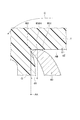
ここで、らせん形状の刃を有するエンドミルを用いることが好適であり、特に、刃の断面形状において、図3におけるdZ及びdZ/dXが小さいエンドミルを用いることが好ましい。 Here, it is preferable to use an end mill having a spiral blade, and in particular, it is preferable to use an end mill having a small dZ and dZ / dX in FIG. 3 in the cross-sectional shape of the blade.
ここで、図3はエンドミルの軸に垂直な断面における刃80の先端の断面図であり、エンドミルの回転方向がCである。この刃80は、刃先80tと、刃先80tよりも後ろ側の面80dとを有する。この面80dは、刃先80tによる切削直後に切削物Tと接触しうる。本実施形態では、刃先80tとエンドミルの回転軸AXを結ぶ直線Qを基準とし、刃先80tを開始点とし、直線Qと直交しかつ刃先80tを通る直線ABに沿って移動しながら、走査型干渉顕微鏡により、直線ABを基準とした面80dの高さのプロファイルを測定する。そして、このプロファイルから面80dの高さの最大値であるdZ[μm]と、dZを与えるAB方向の刃先80tからの距離dX[μm]を求める。
Here, FIG. 3 is a cross-sectional view of the tip of the
このときに、dZ≦1.0μmとなり、dZ/dX≦4となる刃先を有するエンドミルを用いることが好適である。これにより、偏光子層30の端面20eにおける表面粗さを上述の範囲としやすい。らせん状の刃を有するエンドミルであっても、dZ>1.0μm又はdZ/dX>4となるエンドミルでは、表面粗さが大きくなりすぎる傾向がある。
At this time, it is preferable to use an end mill having a cutting edge in which dZ ≦ 1.0 μm and dZ / dX ≦ 4. As a result, the surface roughness of the end face 20e of the
以上、本発明の好適な実施形態について説明したが、本発明は上記実施形態に何ら限定されるものではない。 Although the preferred embodiment of the present invention has been described above, the present invention is not limited to the above embodiment.
例えば、接着剤層20及び40の一方又は両方が無くても実施は可能である。
For example, it can be carried out without one or both of the
以下、実施例及び比較例を挙げて本発明の内容をより具体的に説明する。なお、本発明は下記実施例に限定されるものではない。 Hereinafter, the contents of the present invention will be described more specifically with reference to Examples and Comparative Examples. The present invention is not limited to the following examples.
[実施例1]
厚み20μmのポリビニルアルコール系樹脂フィルムを延伸し、ヨウ素で染色することにより、ポリビニルアルコール系樹脂にヨウ素が吸着配向した偏光子(厚み8μm)を作製した。この偏光子の一方の面に、水系接着剤を介して、環状オレフィン系樹脂(COP)フィルム(日本ゼオン株式会社製、厚み13μm)を貼合した。さらに、COPフィルム上に、剥離フィルム上に形成されたアクリル系粘着剤層A(厚み20μm)を積層した。偏光子の他方の面に、剥離フィルム上に形成されたアクリル系粘着剤層B(厚み5μm)を積層した。剥離フィルムを剥離して露出したアクリル系粘着剤層B上に、プロテクトフィルムを上面に有する輝度向上フィルム(3M社製、APF−V3、厚み30μm、反射型偏光子)を貼合した。
このようにして、剥離フィルム/アクリル系粘着剤層A/COPフィルム/水系接着剤/偏光子/アクリル系粘着剤層B/輝度向上フィルム/プロテクトフィルムからなる偏光板の原反を作製した。
[Example 1]
A polyvinyl alcohol-based resin film having a thickness of 20 μm was stretched and dyed with iodine to prepare a polarizer (thickness: 8 μm) in which iodine was adsorbed and oriented on the polyvinyl alcohol-based resin. A cyclic olefin resin (COP) film (manufactured by Nippon Zeon Corporation, thickness 13 μm) was attached to one surface of the polarizer via an aqueous adhesive. Further, an acrylic pressure-sensitive adhesive layer A (
In this way, the original fabric of the polarizing plate composed of the release film / acrylic pressure-sensitive adhesive layer A / COP film / water-based adhesive / polarizer / acrylic pressure-sensitive adhesive layer B / brightness improving film / protect film was produced.
原反から、トムソン刃により、図2の(b)の形状の凹部PDを有する偏光板100を切り出した。矩形の長辺の長さは140mm、矩形の短辺の長さは70mm、凹みの深さは5mm、凹みの幅は30mm、面取り曲線部PRの曲率半径は概ね10〜12mm、面取り曲線部PDRの曲率半径は概ね3mmとした。なお、この偏光板100は、1つの凹部PDを有する。この凹部PDは、略矩形である。この凹部PDは、隣同士で直交する3つの直線部PDLを有する。直線部PDL間にはそれぞれ面取り曲線部PDRを有する。直線部PDLと直線部PLとの間にはそれぞれ面取り曲線部PDRを有する。この偏光板100の吸収軸31は、凹部PDの深さ方向に直交しており、図2の(b)において左右方向であった。
A
dZが平均で0.6μm、dZ/dXが平均で2.2のらせん径形状の刃を有するエンドミルを用いて、端面の全周を研磨して寸法を調整し、実施例1の偏光板を得た。 Using an end mill having a blade having a spiral diameter with an average dZ of 0.6 μm and an average dZ / dX of 2.2, the entire circumference of the end face was polished to adjust the dimensions, and the polarizing plate of Example 1 was used. Obtained.
(比較例1)
dZが平均で1.4μm、dZ/dXが平均で14のらせん径形状の刃を有するエンドミルを用いて端面を研磨する以外は、実施例1と同様にして比較例1の偏光板を得た。
(Comparative Example 1)
A polarizing plate of Comparative Example 1 was obtained in the same manner as in Example 1 except that the end face was polished using an end mill having a blade having an average dZ of 1.4 μm and an average dZ / dX of 14 spiral diameters. ..
(比較例2)
エンドミルで端面を研磨せず、トムソン刃で切り出したままとした以外は、比較例1と同様として、比較例2の偏光板を得た。
(Comparative Example 2)
A polarizing plate of Comparative Example 2 was obtained in the same manner as in Comparative Example 1 except that the end face was not polished by an end mill and was cut out by a Thomson blade.
(3次元表面における粗さSa、Sq、Szの測定)
偏光子層の端面の高さ関数Z(x,y)を、以下の顕微鏡により取得した。
走査型白色干渉顕微鏡 VS1000シリーズ 株式会社日立ハイテクサイエンス
測定条件:対物レンズ:50×
2次元測定領域:偏光板の偏光子層(PVA層)の端面の直線部(吸収軸と直交する面)における、縦(厚み方向)5〜8μm×横(厚み方向に垂直な方向)150〜300μm
得られた関数Zに基づいて、上記の式に基づいて、Sa、SqおよびSzをそれぞれ求めた。Sa、SqおよびSzを測定した端面は、図2の(b)における左右の直線部PL上に位置し、吸収軸31に対して直交していた。なお、各偏光板100におけるSa、SqおよびSzは、全周に亘って同様の値を示す。
(Measurement of roughness Sa, Sq, Sz on a three-dimensional surface)
The height function Z (x, y) of the end face of the polarizer layer was obtained by the following microscope.
Scanning White Interference Microscope VS1000 Series Hitachi High-Tech Science Corporation Measurement conditions: Objective lens: 50 x
Two-dimensional measurement area: Vertical (thickness direction) 5 to 8 μm × horizontal (direction perpendicular to the thickness direction) 150 to the straight portion (plane orthogonal to the absorption axis) of the end face of the polarizing element layer (PVA layer) of the polarizing plate. 300 μm
Based on the obtained function Z, Sa, Sq and Sz were obtained, respectively, based on the above equation. The end faces on which Sa, Sq and Sz were measured were located on the left and right straight line portions PL in FIG. 2B and were orthogonal to the
(ヨウ素抜けの評価)
実施例又は比較例で得た偏光板を、65℃及び相対湿度90%の環境に500時間放置した。
その後、2枚の偏光板(一方は実施例又は比較例の偏光板、他方は市販の通常の偏光板)をクロスニコルに配置し、光学顕微鏡を用いて全周に亘って端部を観察し、クロスニコルに対応する減光が起こらない領域(光抜け)の端部からの幅を測定した。この光抜けは、偏光性能を発現する役割を担うヨウ素が抜けたことによっておこる。なお、光抜けは、図2における凹部PDの近傍で発生しており、その最大の幅をヨウ素抜けとして求めた。
(Evaluation of iodine loss)
The polarizing plate obtained in Example or Comparative Example was left in an environment of 65 ° C. and 90% relative humidity for 500 hours.
After that, two polarizing plates (one of which is a polarizing plate of an example or a comparative example and the other of which is a commercially available ordinary polarizing plate) are placed on the cross Nicol, and the end portion is observed over the entire circumference using an optical microscope. , The width from the end of the region (light loss) corresponding to the cross Nicol where dimming does not occur was measured. This light leakage is caused by the removal of iodine, which plays a role in developing polarization performance. The light leakage occurred in the vicinity of the concave portion PD in FIG. 2, and the maximum width thereof was determined as iodine leakage.
(輝度向上フィルムの剥離量の評価)
反射型顕微鏡により評価した。
(Evaluation of peeling amount of brightness improving film)
It was evaluated by a reflective microscope.
条件及び結果を表1に示す。
実施例では、ヨウ素抜け量を低減しつつ輝度向上フィルムの剥離量も低減することができた。 In the examples, the amount of peeling of the brightness improving film could be reduced while reducing the amount of iodine removed.
本発明に係る偏光板は、例えば、液晶セル又は有機EL素子等に貼着され、液晶テレビ、有機ELテレビ又はスマートフォン等の画像表示装置を構成する光学部品として適用される。 The polarizing plate according to the present invention is attached to, for example, a liquid crystal cell or an organic EL element, and is applied as an optical component constituting an image display device such as a liquid crystal television, an organic EL television, or a smartphone.
10…第一光学樹脂フィルム、30…偏光子層、50…第二光学樹脂フィルム、P…外周縁、PP…凸部、PD…凹部、PR、PDR、PPR…面取り曲線部、100…偏光板。
10 ... First optical resin film, 30 ... Polarizer layer, 50 ... Second optical resin film, P ... Outer peripheral edge, PP ... Convex part, PD ... Concave part, PR, PDR, PPR ... Chamfered curved part, 100 ... Polarizing plate ..
Claims (4)
前記偏光板を厚み方向から見て、前記偏光板の外周縁の形状は、凹部、凸部、及び曲線部のうちの少なくとも一つを有し、
前記偏光子層の端面の算術平均高さSaが0.3〜0.7μmである、偏光板。 A polarizing plate including a polarizing element layer, a first optical resin film provided on one surface of the polarizer layer, and a second optical resin film provided on the other surface of the polarizer layer. ,
When the polarizing plate is viewed from the thickness direction, the shape of the outer peripheral edge of the polarizing plate has at least one of a concave portion, a convex portion, and a curved portion.
A polarizing plate having an arithmetic mean height Sa of the end face of the polarizer layer of 0.3 to 0.7 μm.
前記偏光板を厚み方向から見て、前記偏光板の外周縁の形状は、凹部、凸部、及び曲線部のうちの少なくとも一つを有し、
前記偏光子層の端面の2乗平均平方根高さSqが0.4〜0.8μmである偏光板。 A polarizing plate including a polarizing element layer, a first optical resin film provided on one surface of the polarizer layer, and a second optical resin film provided on the other surface of the polarizer layer. ,
When the polarizing plate is viewed from the thickness direction, the shape of the outer peripheral edge of the polarizing plate has at least one of a concave portion, a convex portion, and a curved portion.
A polarizing plate having a root mean square height Sq of 0.4 to 0.8 μm on the end face of the polarizer layer.
The polarizing plate according to any one of claims 1 to 3, wherein the maximum height Sz of the end face of the polarizer layer is 5.0 μm or less.
Applications Claiming Priority (4)
| Application Number | Priority Date | Filing Date | Title |
|---|---|---|---|
| JP2019046826 | 2019-03-14 | ||
| JP2019046826 | 2019-03-14 | ||
| JP2019083239 | 2019-04-24 | ||
| JP2019083239 | 2019-04-24 |
Related Child Applications (1)
| Application Number | Title | Priority Date | Filing Date |
|---|---|---|---|
| JP2020205110A Division JP7284141B2 (en) | 2019-03-14 | 2020-12-10 | Polarizer |
Publications (1)
| Publication Number | Publication Date |
|---|---|
| JP2020181184A true JP2020181184A (en) | 2020-11-05 |
Family
ID=72426399
Family Applications (2)
| Application Number | Title | Priority Date | Filing Date |
|---|---|---|---|
| JP2020013914A Pending JP2020181184A (en) | 2019-03-14 | 2020-01-30 | Polarizer |
| JP2020205110A Active JP7284141B2 (en) | 2019-03-14 | 2020-12-10 | Polarizer |
Family Applications After (1)
| Application Number | Title | Priority Date | Filing Date |
|---|---|---|---|
| JP2020205110A Active JP7284141B2 (en) | 2019-03-14 | 2020-12-10 | Polarizer |
Country Status (5)
| Country | Link |
|---|---|
| JP (2) | JP2020181184A (en) |
| KR (1) | KR20210138567A (en) |
| CN (1) | CN113574426B (en) |
| TW (1) | TW202041897A (en) |
| WO (1) | WO2020184030A1 (en) |
Families Citing this family (1)
| Publication number | Priority date | Publication date | Assignee | Title |
|---|---|---|---|---|
| JP7203879B2 (en) * | 2021-03-25 | 2023-01-13 | 日東電工株式会社 | Method for manufacturing polarizing plate and polarizing plate |
Citations (9)
| Publication number | Priority date | Publication date | Assignee | Title |
|---|---|---|---|---|
| JP2007223021A (en) * | 2006-01-27 | 2007-09-06 | Nitto Denko Corp | Cutting method and manufacturing method for sheet-like member, sheet-like member, optical element and image display device |
| JP2009037228A (en) * | 2007-07-06 | 2009-02-19 | Nitto Denko Corp | Polarization plate |
| JP2011020192A (en) * | 2009-07-14 | 2011-02-03 | Sumitomo Electric Hardmetal Corp | Spiral radius end mill |
| WO2017047510A1 (en) * | 2015-09-16 | 2017-03-23 | シャープ株式会社 | Method for producing differently shaped polarizing plate |
| JP2018012182A (en) * | 2016-07-22 | 2018-01-25 | 日東電工株式会社 | Method and apparatus for manufacturing polarization plate |
| JP2018022140A (en) * | 2016-07-22 | 2018-02-08 | 日東電工株式会社 | Manufacturing method of polarizing plate and manufacturing apparatus thereof |
| JP2018063401A (en) * | 2016-10-14 | 2018-04-19 | 住友化学株式会社 | Polarizer, polarizing plate, and image display apparatus |
| JP2019018308A (en) * | 2017-07-20 | 2019-02-07 | 住友化学株式会社 | Cutting device and polarizer manufacturing method |
| JP2019020648A (en) * | 2017-07-20 | 2019-02-07 | 住友化学株式会社 | Method for manufacturing polarizing plate |
Family Cites Families (16)
| Publication number | Priority date | Publication date | Assignee | Title |
|---|---|---|---|---|
| JP2000026817A (en) * | 1998-07-14 | 2000-01-25 | Teijin Ltd | Surface-protective film |
| KR20070015453A (en) * | 2004-05-11 | 2007-02-02 | 닛토덴코 가부시키가이샤 | Polarizer protecting film, polarizing plate and image display |
| JP5525764B2 (en) * | 2009-06-15 | 2014-06-18 | 日東電工株式会社 | Release film, protective film for polarizing plate using the release film, and polarizing plate using protective film for the polarizing plate |
| JP6172980B2 (en) * | 2012-03-14 | 2017-08-02 | 日東電工株式会社 | Manufacturing method of liquid crystal display panel |
| JP6656799B2 (en) * | 2013-11-29 | 2020-03-04 | 王子ホールディングス株式会社 | Anti-Newton ring laminate and capacitive touch panel using the anti-Newton ring laminate |
| JP5979123B2 (en) * | 2013-12-05 | 2016-08-24 | 住友化学株式会社 | Polarizer with few bubble defects |
| JP6348291B2 (en) * | 2014-02-04 | 2018-06-27 | 住友化学株式会社 | Polarizing plate and display device |
| JP5886338B2 (en) * | 2014-02-21 | 2016-03-16 | 住友化学株式会社 | Polarizing plate, optical member set, and touch input type image display device |
| JP6258911B2 (en) * | 2014-12-22 | 2018-01-10 | 住友化学株式会社 | Polarizing plate with protective film and laminate including the same |
| JP5976969B1 (en) * | 2015-06-19 | 2016-08-24 | 住友化学株式会社 | Manufacturing method of polarizing plate with protective film |
| JP2017181597A (en) * | 2016-03-28 | 2017-10-05 | 住友化学株式会社 | Optical film and polarizing plate |
| JP6684630B2 (en) * | 2016-03-31 | 2020-04-22 | 住友化学株式会社 | Polarizing plate and method of manufacturing polarizing plate |
| JP6495374B2 (en) | 2016-05-30 | 2019-04-03 | 住友化学株式会社 | Polarizing plate for image display device, image display device, and method for producing polarizing plate for image display device |
| JP2018031954A (en) * | 2016-08-26 | 2018-03-01 | 日東電工株式会社 | Polarizing plate and method for manufacturing the same, and image display device using polarizing plate |
| JP6306675B1 (en) * | 2016-11-28 | 2018-04-04 | 住友化学株式会社 | Method for producing polarizing laminated film with protective film and method for producing polarizing plate |
| KR102510750B1 (en) * | 2017-04-04 | 2023-03-15 | 스미또모 가가꾸 가부시키가이샤 | Polarizing plate with protective film, and liquid crystal panel |
-
2020
- 2020-01-30 JP JP2020013914A patent/JP2020181184A/en active Pending
- 2020-02-10 KR KR1020217022112A patent/KR20210138567A/en unknown
- 2020-02-10 CN CN202080020361.6A patent/CN113574426B/en active Active
- 2020-02-10 WO PCT/JP2020/005103 patent/WO2020184030A1/en active Application Filing
- 2020-02-24 TW TW109105854A patent/TW202041897A/en unknown
- 2020-12-10 JP JP2020205110A patent/JP7284141B2/en active Active
Patent Citations (9)
| Publication number | Priority date | Publication date | Assignee | Title |
|---|---|---|---|---|
| JP2007223021A (en) * | 2006-01-27 | 2007-09-06 | Nitto Denko Corp | Cutting method and manufacturing method for sheet-like member, sheet-like member, optical element and image display device |
| JP2009037228A (en) * | 2007-07-06 | 2009-02-19 | Nitto Denko Corp | Polarization plate |
| JP2011020192A (en) * | 2009-07-14 | 2011-02-03 | Sumitomo Electric Hardmetal Corp | Spiral radius end mill |
| WO2017047510A1 (en) * | 2015-09-16 | 2017-03-23 | シャープ株式会社 | Method for producing differently shaped polarizing plate |
| JP2018012182A (en) * | 2016-07-22 | 2018-01-25 | 日東電工株式会社 | Method and apparatus for manufacturing polarization plate |
| JP2018022140A (en) * | 2016-07-22 | 2018-02-08 | 日東電工株式会社 | Manufacturing method of polarizing plate and manufacturing apparatus thereof |
| JP2018063401A (en) * | 2016-10-14 | 2018-04-19 | 住友化学株式会社 | Polarizer, polarizing plate, and image display apparatus |
| JP2019018308A (en) * | 2017-07-20 | 2019-02-07 | 住友化学株式会社 | Cutting device and polarizer manufacturing method |
| JP2019020648A (en) * | 2017-07-20 | 2019-02-07 | 住友化学株式会社 | Method for manufacturing polarizing plate |
Also Published As
| Publication number | Publication date |
|---|---|
| TW202041897A (en) | 2020-11-16 |
| KR20210138567A (en) | 2021-11-19 |
| JP2021047453A (en) | 2021-03-25 |
| JP7284141B2 (en) | 2023-05-30 |
| CN113574426A (en) | 2021-10-29 |
| CN113574426B (en) | 2024-03-15 |
| WO2020184030A1 (en) | 2020-09-17 |
Similar Documents
| Publication | Publication Date | Title |
|---|---|---|
| JP6899721B2 (en) | Polarizing plate manufacturing method and its manufacturing equipment | |
| JP6201025B1 (en) | Polarizer, polarizing plate and image display device | |
| KR20190027772A (en) | Method for manufacturing polarization plate and manufacturing device therefor | |
| KR102525401B1 (en) | Polarizing plate, liquid crystal panel and liquid crystal display device | |
| JP6172302B2 (en) | Polarizing plate, liquid crystal panel, and liquid crystal display device | |
| US11022735B2 (en) | Method of producing polarizing plate | |
| KR101810367B1 (en) | Polarizing plate and liquid crystal display device | |
| TW201805663A (en) | Polarizing plate and liquid crystal display device | |
| WO2020184030A1 (en) | Polarizing plate | |
| TW201804181A (en) | Laminated film, method of manufacturing laminated film with mark, and method of manufacturing image display device | |
| JP2012048181A (en) | Polarizer and liquid crystal display device using the same | |
| JP6755223B2 (en) | Polarizer, polarizing plate and image display device | |
| JP7221256B2 (en) | A polarizing plate, a polarizing plate with a retardation layer, and an image display device comprising the polarizing plate or the polarizing plate with the retardation layer | |
| KR102256908B1 (en) | Method for manufacturing polarization plate sheet | |
| JP7203879B2 (en) | Method for manufacturing polarizing plate and polarizing plate | |
| JP7018272B2 (en) | Polarizing plate and liquid crystal display device | |
| KR20230118957A (en) | Polarizer set and liquid crystal panel | |
| JP2022039928A (en) | Polarizing plate with hard coat layer and image display device comprising the same | |
| KR20210037527A (en) | Optical laminate and image display device |
Legal Events
| Date | Code | Title | Description |
|---|---|---|---|
| A621 | Written request for application examination |
Free format text: JAPANESE INTERMEDIATE CODE: A621 Effective date: 20200206 |
|
| A871 | Explanation of circumstances concerning accelerated examination |
Free format text: JAPANESE INTERMEDIATE CODE: A871 Effective date: 20200206 |
|
| A975 | Report on accelerated examination |
Free format text: JAPANESE INTERMEDIATE CODE: A971005 Effective date: 20200217 |
|
| A977 | Report on retrieval |
Free format text: JAPANESE INTERMEDIATE CODE: A971007 Effective date: 20200625 |
|
| A131 | Notification of reasons for refusal |
Free format text: JAPANESE INTERMEDIATE CODE: A131 Effective date: 20200630 |
|
| A521 | Request for written amendment filed |
Free format text: JAPANESE INTERMEDIATE CODE: A523 Effective date: 20200828 |
|
| A02 | Decision of refusal |
Free format text: JAPANESE INTERMEDIATE CODE: A02 Effective date: 20200929 |