KR20200083669A - Flatness measurement method and pin-height adjustment method - Google Patents
Flatness measurement method and pin-height adjustment method Download PDFInfo
- Publication number
- KR20200083669A KR20200083669A KR1020207018917A KR20207018917A KR20200083669A KR 20200083669 A KR20200083669 A KR 20200083669A KR 1020207018917 A KR1020207018917 A KR 1020207018917A KR 20207018917 A KR20207018917 A KR 20207018917A KR 20200083669 A KR20200083669 A KR 20200083669A
- Authority
- KR
- South Korea
- Prior art keywords
- measurement
- measuring
- pin
- point
- pins
- Prior art date
Links
Images


Classifications
-
- G—PHYSICS
- G01—MEASURING; TESTING
- G01B—MEASURING LENGTH, THICKNESS OR SIMILAR LINEAR DIMENSIONS; MEASURING ANGLES; MEASURING AREAS; MEASURING IRREGULARITIES OF SURFACES OR CONTOURS
- G01B5/00—Measuring arrangements characterised by the use of mechanical techniques
- G01B5/28—Measuring arrangements characterised by the use of mechanical techniques for measuring roughness or irregularity of surfaces
-
- G—PHYSICS
- G01—MEASURING; TESTING
- G01C—MEASURING DISTANCES, LEVELS OR BEARINGS; SURVEYING; NAVIGATION; GYROSCOPIC INSTRUMENTS; PHOTOGRAMMETRY OR VIDEOGRAMMETRY
- G01C9/00—Measuring inclination, e.g. by clinometers, by levels
Abstract
[과제]
다수의 핀의 상단이 이루는 가상면과 같은 면의 평면도를 간편하게 측정할 수 있는 실용적인 기술을 제공한다.
[해결 수단]
평탄한 상면 및 하면을 가지며 균일한 두께의 측정판(5) 상에 수준기(6)가 부착된 측정 유닛(4)을, 다수의 핀(3) 중 서로 이웃하는 3개의 핀(3) 상에 올린 상태로, 직교하는 2개의 수평 방향에 있어서의 측정판(5)의 기울기를 수준기(6)에 의해 측정하여, 이 단계를 각 3개의 핀(3)에 대해 순차적으로 행한다. 2회째 이후의 단계에서는, 그때까지 선택된 핀(3) 중 한개를 중복해서 선택하면서 모든 핀(3)에 대해서 측정판(5)의 기울기를 선택한다. 측정판(5)의 기울기로부터, 상단이 가장 높은 위치에 있는 핀(3)과 상단이 가장 낮은 위치에 있는 핀(3)의 높이의 차이가 평면도로서 산출된다. [assignment]
It provides a practical technology that can easily measure the planar view of a face such as a virtual face formed by the top of a plurality of pins.
[Solution]
A measuring unit 4 having a flat top and bottom surface and having a level 6 attached to the measuring plate 5 of uniform thickness is placed on three adjacent pins 3 among the plurality of pins 3 In the state, the inclination of the measuring plate 5 in two orthogonal horizontal directions is measured by the level 6, and this step is sequentially performed for each of the three pins 3. In the second and subsequent steps, the inclination of the measuring plate 5 is selected for all the pins 3 while repeatedly selecting one of the pins 3 selected so far. From the inclination of the measuring plate 5, the difference in height between the pin 3 at the highest position at the top and the pin 3 at the lowest position at the top is calculated as a plan view.
Description
이 출원의 발명은, 다수의 핀의 상단이 이루는 가상면 등의 면의 평면도(平面度)를 구하는 기술에 관한 것이다.The invention of this application relates to a technique for obtaining a planarity of a surface such as a virtual surface formed by the upper ends of a plurality of pins.
어느 면이 높은 정밀도로 평면인 것은, 제품의 성능으로서 자주 요구된다. 이 경우의 어느 면이란, 가상적인 면(가상면)인 경우도 있고, 실제의 부재의 표면인 경우도 있다. It is often required as a performance of a product that any surface is flat with high precision. In this case, any surface may be a virtual surface (virtual surface) or a surface of an actual member.
다수의 핀의 상단이 이루는 가상면이 높은 평면도를 가지고 있는 것은, 예를 들면 그러한 핀을 이용하여 대상물을 유지하면서 대상물을 취급하는 장치에 있어서 필요해진다. 보다 구체적인 예를 나타내면, 각종 전자 제품이나 각종 디스플레이 제품의 제조에서는, 기판의 표면에 미세 형상을 만들어 넣기 위해, 포토리소그래피가 행해진다. 포토리소그래피에서는, 기판을 수평으로 유지하면서 소정의 패턴의 광을 기판에 조사하는 노광 공정이 존재하고 있다. 노광 공정에서는, 기판에 대한 접촉 면적을 가능한 한 작게 하는 등의 요청으로부터, 수직인 자세의 다수의 핀에 의해 기판을 유지하는 구조가 채용되는 경우가 있다. It is necessary, for example, in an apparatus for handling an object while holding the object using such a pin that the virtual surface formed by the top of the plurality of pins has a high planarity. To show a more specific example, in the manufacture of various electronic products and various display products, photolithography is performed to make a fine shape on the surface of the substrate. In photolithography, there is an exposure process in which light of a predetermined pattern is irradiated to the substrate while keeping the substrate horizontal. In the exposure process, a structure for holding the substrate by a plurality of pins in a vertical posture may be employed in response to requests such as making the contact area with the substrate as small as possible.
상술한 바와 같은 노광 장치에서는, 정밀도가 높은 노광 패턴을 얻는 관점에서, 기판은 높은 정밀도로 수평 자세를 유지하고 있을 필요가 있다. 이것은, 기판을 다수의 핀으로 유지하는 구조의 경우, 그들 핀의 상단에서 형성되는 가상면이 높은 정밀도의 평면도를 가질 필요가 있는 것을 의미한다. In the exposure apparatus as described above, from the viewpoint of obtaining a high-precision exposure pattern, the substrate needs to maintain a horizontal attitude with high precision. This means that in the case of a structure in which the substrate is held by a plurality of pins, the virtual surfaces formed at the tops of those pins need to have a high-precision plan view.
그러나, 발명자가 조사한 바로는, 이러한 다수의 핀의 상단이 이루는 가상면의 평면도를 간편하게 측정할 수 있는 실용적인 기술은, 현재 존재하고 있지 않다. However, from the research of the inventor, there is currently no practical technique that can easily measure the planar view of the virtual surface formed by the upper ends of the plurality of pins.
본원의 발명은, 이 점이 고려하여 이루어진 것이며, 다수의 핀의 상단이 이루는 가상면과 같은 면의 평면도를 간편하게 측정할 수 있는 실용적인 기술을 제공하는 것을 과제로 하고 있다. The invention of the present application has been made in consideration of this point, and an object of the present invention is to provide a practical technique capable of easily measuring a plan view of a surface such as a virtual surface formed by the top of a plurality of pins.
상기 과제를 해결하기 위해, 이 출원의 청구항 1에 기재된 발명은, 수평 방향의 배치를 이미 알고 있으며 수직으로 연장되는 다수의 핀의 상단의 높이 방향의 위치의 상이를 당해 다수의 핀의 선단이 이루는 가상면의 평면도로서 측정하는 평면도 측정 방법으로서, In order to solve the above problems, the invention described in
평탄한 상면 및 하면을 가지며 균일한 두께의 측정판과, 측정판 상에 부착된 수준기로 이루어지는 측정 유닛을 사용하는 방법이며, It is a method of using a measuring unit having a flat upper and lower surfaces and having a uniform thickness and a level attached to the measuring plate.
다수의 핀 중 서로 이웃하는 3개의 핀을 선택하고, 선택된 3개의 핀 상에 측정 유닛을 올린 상태로, 직교하는 2개의 수평 방향에 있어서의 측정판의 기울기를 수준기에 의해 측정하는 3점 측정 단계를 포함하는 방법이며, Three-point measuring step of selecting three pins adjacent to each other among a plurality of pins, and measuring the inclination of the measuring plate in two orthogonal two horizontal directions with a measuring unit on the selected three pins. How to include,
3점 측정 단계를 각 3개의 핀에 대해 순차적으로 행함으로써 평면도를 측정하는 방법이며, It is a method to measure the top view by sequentially performing the three-point measuring step for each of the three pins.
2회째 이후의 3점 측정 단계는, 그때까지 선택된 핀 중 한개를 중복해서 선택하여 측정을 행하는 단계이며, The three-point measurement step after the second time is a step in which one of the selected pins up to that point is selected and measured.
3점 측정 단계를 순차적으로 행함으로써 모든 핀에 대해서 수준기에 의해 측정판의 기울기를 측정하는 방법이며, It is a method to measure the inclination of the measuring plate by the level on all pins by sequentially performing the three-point measuring step.
각 3점 측정 단계에서의 상기 2개의 수평 방향의 측정판의 기울기로부터, 상단이 가장 높은 위치에 있는 핀과 상단이 가장 낮은 위치에 있는 핀의 당해 높이의 차이를 산출하는 단계를 포함한다는 구성을 가진다. Comprising the step of calculating the difference between the height of the pin at the highest position and the pin at the highest position from the slope of the two horizontal measuring plate in each three-point measurement step. Have
또, 상기 과제를 해결하기 위해, 청구항 2에 기재된 발명은, 수평 방향의 배치를 이미 알고 있는 다수의 측정점 마크를 구비한 물체의 상면의 수평 방향에서의 평면도를 측정하는 평면도 측정 방법이며, Moreover, in order to solve the said subject, the invention of
평탄한 상면을 가지는 측정판과, 측정판 상에 부착된 수준기와, 측정판의 하면으로부터 하방으로 수직으로 연장되며, 측정판의 상면으로부터의 길이가 균일한 3개의 다리 핀을 구비한 측정 유닛을 사용하는 방법이며, A measuring unit having a flat top surface, a level attached to the measuring plate, and vertically extending downwardly from the bottom surface of the measuring plate, and a measuring unit having three leg pins of uniform length from the top surface of the measuring plate are used. How to do it,
다수의 측정점 마크의 배치는, 서로 이웃하는 어느 3개의 측정점 마크를 선택한 경우에도 측정 유닛의 3개의 다리 핀의 배치와 동일해지는 배치이며, The arrangement of the multiple measurement point marks is the same as the arrangement of the three leg pins of the measurement unit even when any three measurement point marks adjacent to each other are selected,
다수의 측정점 마크 중 서로 이웃하는 3개의 측정점 마크를 선택하고, 선택된 3개의 측정점 마크 상에 측정 유닛의 다리 핀이 각각 올려지는 상태로, 직교하는 2개의 수평 방향에 있어서의 측정판의 기울기를 수준기에 의해 측정하는 3점 측정 단계를 포함하는 방법이며, Among the multiple measurement point marks, three measurement point marks which are adjacent to each other are selected, and the leg pins of the measurement unit are raised on the three selected measurement point marks, respectively, and level the inclination of the measurement plate in two orthogonal horizontal directions. Method comprising a three-point measuring step to measure by,
3점 측정 단계를, 각 3개의 측정점 마크에 대해 순차적으로 행함으로써 평면도를 측정하는 방법이며, It is a method of measuring a plan view by sequentially performing a three-point measuring step for each of the three measuring point marks,
2회째 이후의 3점 측정 단계는, 그때까지 선택된 3개의 측정점 마크 중 한개를 중복해서 선택하여 측정을 행하는 단계이며, The third-point measurement step after the second time is a step of repeatedly selecting one of the three measurement point marks selected so far and performing measurement,
3점 측정 단계를 순차적으로 행함으로써 모든 측정점 마크에 대해서 수준기에 의해 측정판의 상면의 기울기를 측정하는 방법이며, It is a method to measure the inclination of the upper surface of the measuring plate by level using all the measuring point marks by sequentially performing the three-point measuring step.
각 3점 측정 단계에서의 상기 2개의 수평 방향의 측정판의 상면의 기울기로부터, 가장 높은 위치에 있는 측정점 마크와 가장 낮은 위치에 있는 측정점 마크의 높이의 차이를 산출하는 단계를 포함한다는 구성을 가진다. And calculating the difference between the height of the measurement point mark at the highest position and the measurement point mark at the lowest position from the inclinations of the upper surfaces of the two horizontal measurement plates in each three-point measurement step. .
또, 상기 과제를 해결하기 위해, 청구항 3에 기재된 발명은, 베이스반(盤)과, 베이스반의 상면에 부착되어 수직 상방으로 연장되는 다수의 핀을 구비하고, 각 핀의 돌출 높이를 조정 가능한 핀 유닛에 있어서, 각 핀의 베이스반으로부터의 돌출 높이를 조정하는 핀 높이 조정 방법으로서, In addition, in order to solve the above problems, the invention described in
다수의 핀의 상단의 높이 방향의 위치의 상이를 당해 다수의 핀의 선단이 이루는 가상면의 평면도로서 측정하는 평면도 측정 공정과, A planarity measuring process for measuring a difference in position in the height direction of the upper end of the plurality of pins as a plan view of a virtual surface formed by the tip of the plurality of pins
평면도 측정 공정에 있어서의 평면도의 측정 결과에 따라서 각 핀의 돌출 높이를 조정하는 조정 공정을 가지고 있으며, In the flatness measurement process, there is an adjustment process for adjusting the protruding height of each pin according to the measurement result of the flatness,
평면도 측정 공정은, 평탄한 상면 및 하면을 가지며 균일한 두께의 측정판과, 측정판 상에 부착된 수준기로 이루어지는 측정 유닛을 사용하는 공정이며, 다수의 핀 중 서로 이웃하는 3개의 핀을 선택하고, 선택된 3개의 핀 상에 측정 유닛을 올린 상태로, 직교하는 2개의 수평 방향에 있어서의 측정판의 기울기를 수준기에 의해 측정하는 3점 측정 단계를 포함하는 공정이며, The planarity measuring process is a process using a measuring unit having a flat upper surface and a lower surface and having a uniform thickness and a level attached to the measuring plate, and among the multiple pins, three adjacent pins are selected, It is a process including a three-point measuring step of measuring the inclination of the measuring plate in two orthogonal two horizontal directions with the measuring unit on the three selected pins, by a level,
평면도 측정 공정은, 3점 측정 단계를, 각 3개의 핀에 대해 순차적으로 행함으로써 평면도를 측정하는 공정이며, The plan view measurement process is a process of measuring a plan view by sequentially performing a three-point measurement step for each of the three pins,
2회째 이후의 3점 측정 단계는, 그때까지 선택된 3개 중 한개를 중복해서 선택하여 측정을 행하는 단계이며, The three-point measurement step after the second time is a step of repeatedly selecting and measuring one of the three selected so far,
평면도 측정 공정은, 3점 측정 단계를 순차적으로 행함으로써 모든 핀에 대해서 수준기에 의해 측정판의 기울기를 측정하는 공정이며, The planarity measurement process is a process of sequentially measuring the inclination of the measuring plate by a level on all pins by sequentially performing a three-point measurement step.
평면도 측정 공정은, 각 3점 측정 단계에서의 상기 2개의 수평 방향의 측정판의 기울기로부터, 상단이 가장 높은 위치에 있는 핀과 상단이 가장 낮은 위치에 있는 핀의 당해 높이의 차이를 산출하는 단계를 포함하고 있으며, The plan view measuring process calculates a difference between the heights of the pins at the highest position and the pins at the lowest position at the top from the inclinations of the two horizontal measurement plates in each three-point measurement step. It contains,
조정 공정은, 평면도 측정 공정에서 측정된 높이의 차이를 작게 하도록 각 핀의 돌출 높이를 조정하는 방법이라는 구성을 가진다. The adjustment process has a structure called a method of adjusting the protruding height of each pin so as to reduce the difference in height measured in the flatness measurement process.
또, 상기 과제를 해결하기 위해, 청구항 4에 기재된 발명은, 상기 청구항 3의 구성에 있어서, 상기 조정 공정은, 상기 베이스반과 상기 핀의 사이에 심을 개재시키는 공정이며, 상기 평면도 측정 공정에 있어서의 측정 결과에 따라서 심의 두께를 선택하는 공정이라는 구성을 가진다. Moreover, in order to solve the said subject, the invention of
또, 상기 과제를 해결하기 위해, 청구항 5에 기재된 발명은, 상기 청구항 3 또는 청구항 4의 구성에 있어서, 상기 조정 공정을 행한 후, 상기 평면도 측정 공정을 재차 행하여, 각 핀의 상단의 높이의 차이가 일정 범위 내에 들어가 있는지 판단하여, 들어가 있지 않으면, 상기 조정 공정을 재차 행한다는 구성을 가진다. Moreover, in order to solve the said subject, the invention of
이하에 설명하는 대로, 이 출원의 청구항 1에 기재된 발명에 의하면, 다수의 핀의 상단이 이루는 가상면의 평면도를 간편하게 측정할 수 있다. 측정에 사용하는 툴에 대해서도, 수준기와 측정판을 조합한 심플한 것이므로, 저비용으로 실현할 수 있다. 이 때문에, 극히 실용적인 측정 방법이 된다. As described below, according to the invention described in
또, 청구항 2에 기재된 발명에 의하면, 물체의 상면의 평면도를 간편하게 측정할 수 있다. 측정에 사용하는 툴에 대해서도, 수준기와 측정판과 다리 핀을 조합한 심플한 것이므로, 저비용으로 실현할 수 있다. 이 때문에, 극히 실용적인 측정 방법이 된다. Moreover, according to the invention described in
또, 청구항 3에 기재된 발명에 의하면, 측정 유닛을 사용하여 측정 단계를 반복함으로써 평면도를 측정하고, 이것에 의거하여 핀 높이를 조정하므로, 간편한 절차로 측정 결과를 얻어 조정을 행할 수 있다. 이 때문에, 측정과 조정을 반복하는 경우에도, 수고가 들지 않고, 번잡해지지 않는다. In addition, according to the invention described in
또, 청구항 4에 기재된 발명에 의하면, 상기 효과에 더하여, 심을 사용하므로, 각 핀의 돌출 높이의 조정을 간편하고 확실히 행할 수 있다. Moreover, according to the invention described in
또, 청구항 5에 기재된 발명에 의하면, 상기 효과에 더하여, 특히 높은 평면도가 요구되는 경우에 적합한 방법이 제공된다. Moreover, according to the invention described in
도 1은 제1 실시 형태의 평면도 측정 방법이 실시되는 핀 유닛의 사시 개략도이다.
도 2는 제1 실시 형태의 방법에 사용되는 측정 유닛의 사시 개략도이다.
도 3은 제1 실시 형태의 평면도 측정 방법을 나타낸 평면 개략도이다.
도 4는 제1 실시 형태의 평면도 측정 방법을 나타낸 평면 개략도이다.
도 5는 실시 형태의 평면도 측정 방법에 있어서, 각 측정 데이터로부터 평면도를 산출하는 연산 처리의 주요부에 대해서 나타낸 사시 개략도이다.
도 6은 표계산 소프트웨어에 의한 연산 처리 단계의 실행예를 개략적으로 나타낸 도이다.
도 7은 실시 형태에 관련된 핀 높이 조정 방법을 나타낸 정면 개략도이다.
도 8은 제2 실시 형태의 평면도 측정 방법의 개략을 나타낸 사시도이다. 1 is a perspective schematic view of a pin unit in which the plan view measuring method of the first embodiment is implemented.
2 is a perspective schematic view of a measurement unit used in the method of the first embodiment.
3 is a schematic plan view showing a plan view measuring method of the first embodiment.
4 is a plan schematic view showing a plan view measuring method of the first embodiment.
Fig. 5 is a perspective schematic view showing the main parts of a calculation process for calculating a plan view from each measurement data in the plan view measurement method of the embodiment.
6 is a diagram schematically showing an example of execution of the calculation processing step by the table calculation software.
7 is a front schematic view showing a pin height adjustment method according to an embodiment.
8 is a perspective view schematically illustrating a plan view measuring method of a second embodiment.
다음에, 이 출원의 발명을 실시하기 위한 형태(이하, 실시 형태)에 대해서 설명한다. Next, a form (hereinafter, embodiment) for carrying out the invention of this application will be described.
이 출원의 발명은, 어느 면의 평면도를 측정하는 방법인데, 그 실시 형태는, 수직으로 연장되는 다수의 핀의 상단이 이루는 가상면에 대해서 그 평면도를 측정하는 방법과, 어느 부재의 상면에 대해서 그 평면도를 측정하는 방법으로 크게 구별된다. The invention of this application is a method of measuring the flatness of a certain surface, the embodiment of which is a method of measuring the flatness of a virtual surface formed by the upper ends of a plurality of vertically extending pins, and the upper surface of a certain member. It is largely distinguished by the method of measuring the flatness.
이하, 제1 실시 형태로서, 다수의 핀의 상단이 이루는 가상면의 평면도를 측정하는 방법에 대해서 설명한다. 도 1은, 제1 실시 형태의 평면도 측정 방법이 실시되는 핀 유닛의 사시 개략도이다. Hereinafter, as a first embodiment, a method of measuring a plan view of a virtual surface formed by the upper ends of a plurality of pins will be described. 1 is a perspective schematic view of a pin unit in which the plan view measuring method of the first embodiment is implemented.
실시 형태의 평면도 측정 방법이 실시되는 핀 유닛(1)은, 베이스반(2)과, 베이스반(2)의 상면에 부착된 다수의 핀(3)을 구비하고 있다. 다수의 핀(3)은, 도 1에 나타내는 바와 같이, 수직으로 세워 부착되어 있다. 베이스반(2)의 상면은, 필요한 정밀도의 수평이며 평탄한 면으로 되어 있다. 각 핀(3)은, 베이스반(2)의 상면으로부터의 돌출 높이가 일정해지도록 부착되어 있다. 예를 들면 각 핀(3)은 모두 같은 길이의 것이며, 나사식 삽입으로 부착되어 있다. 따라서, 각 핀(3)의 상단은, 이론적으로는 동일한 가상의 수평면 상에 위치할 것이다. 그러나, 각 핀(3)의 치수 정밀도, 부착 정밀도(삽입 깊이 등), 베이스반(2)의 상면의 평면 정밀도 등의 각 요인이 서로 영향을 주는 결과, 각 핀(3)의 상단은, 같은 높이의 위치에 필요한 정밀도로 위치하는 일은 적다. 즉, 각 핀(3)의 상단이 이루는 가상면은, 필요한 평면도를 가지지 않은 경우가 있을 수 있다. 실시 형태의 방법은, 측정에 의해 이것을 검출하는 것으로 되어 있다. The
또한, 도 1에 나타내는 바와 같이, 각 핀(3)은, 바둑판의 눈금 상(직각 격자의 각 교점 상)의 위치에 배치되어 있다. 서로 이웃하는 핀(3)의 간격은 모두 같다. Moreover, as shown in FIG. 1, each
도 2는, 제1 실시 형태의 방법에 사용되는 측정 유닛(4)의 사시 개략도이다. 도 2에 나타내는 측정 유닛(4)은, 측정판(5)과, 측정판(5) 상에 부착된 수준기(6)를 구비하고 있다. 2 is a perspective schematic view of the
측정판(5)은, 측정 대상인 각 핀(3)과 수준기(6)의 사이에 위치하기 때문에, 필요한 평탄성을 가지는 것으로 되어 있다. 즉, 측정판(5)은, 충분히 평탄한 상면 및 하면을 가지는 일정한 두께의 판으로 되어 있다. 측정판(5)의 재질에는 특별히 제한은 없지만, 스테인리스나 알루미늄과 같은 금속인 경우가 많다. 측정판(5)은, 도 2에 나타내는 바와 같이, 모따기된 직각 이등변 삼각형의 형상이다. Since the measuring
수준기(6)로서는, 이 실시 형태에서는, 디지털식의 2축 수준기가 사용되어 있다. 즉, 수준기(6)는, 직교하는 2개의 수평 방향에 있어서의 측정판(5)의 기울기를 측정하는 것이 가능한 것으로 되어 있다. As the
이 실시 형태에서는, 수준기(6)는, 무선 통신에 의해 데이터를 보내는 것으로 되어 있다. 수준기(6)는, 내장된 송신부(61)와, 송신부(61)로부터 송신된 측정 데이터를 수신하는 수신부(62)를 구비하고 있다. 수신부(62)는, 수준기(6)를 제어하는 리모트 콘트롤러로서 기능하는 것이다. 송신부(61) 및 수신부(62)는, 특정 소전력 무선, 적외선 통신, Bluetooth(등록상표)와 같은 적당한 규격에 의해 무선 통신하는 것으로 되어 있다. 이러한 수준기(6)로서는, 예를 들면 사카모토 전기 제작소제의 SEL-121BM을 사용할 수 있다. In this embodiment, the
또한, 측정 유닛(4)은, 평면도의 측정을 위한 연산 처리를 행하는 연산 처리 유닛(7)과 함께 사용된다. 연산 처리 유닛(7)으로서는, 각종의 구성을 상정할 수 있는데, 이 실시 형태에서는, 데스크탑 PC와 같은 범용 컴퓨터가 사용되고 있다. 수준기(6)의 수신부(62)와 연산 처리 유닛(7)으로서의 범용 컴퓨터는, USB와 같은 범용 인터페이스의 케이블(71)을 통하여 접속되어 있다. 연산 처리 유닛(7)에는, 수준기(6)로부터 출력되는 측정 데이터를 처리하여 평면도를 산출하는 프로그램이 실장되어 있다. Moreover, the
다음에, 측정 유닛(4)을 사용한 평면도 측정 방법으로 대해서, 도 3 및 도 4를 사용하여 설명한다. 도 3 및 도 4는, 제1 실시 형태의 평면도 측정 방법을 나타낸 평면 개략도이다. Next, a plan view measuring method using the
실시 형태의 평면도 측정 방법은, 직교하는 2개의 수평 방향에 있어서의 측정판(5)의 기울기를 측정할 수 있도록, 다수의 핀(3) 중 서로 이웃하는 3개의 핀(3)을 선택하고, 선택된 3개의 핀(3) 상에 측정 유닛(4)을 올린 상태로 수준기(6)에 의해 측정판(5)의 기울기를 측정하는 단계(이하, 3점 측정 단계라고 한다)를 순차적으로 행하는 방법이다. 「순차적으로 행한다」란, 각 3개의 핀(3)에 대해 순차적으로 행하는 것이다. 2회째 이후의 3점 측정 단계는, 그때까지 선택된 3개 핀(3) 중 한개를 중복해서(공통으로) 선택하는 측정을 행하는 단계이다. In the plan view measuring method of the embodiment, three
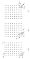
도 3에 있어서, 각 핀의 배열 방향을 X방향, Y방향으로 한다. 핀은, X방향으로 m개, Y방향으로 n개인 것으로 한다. 또, 설명을 간단하게 하기 위해, 수준기(6)의 측정 방향(2축의 방향)은, X방향 및 Y방향으로 동일한 것으로 한다. 따라서, 베이스반(2)은, 미리 핀의 배열 방향이 수준기(6)의 측정 방향과 일치하도록 정밀도 있게 배치된다(위치 결정된다). 3, the arrangement direction of each pin is set to the X direction and the Y direction. It is assumed that the number of pins is m in the X direction and n in the Y direction. In addition, for simplicity, the measurement direction of the level 6 (the direction of the two axes) is assumed to be the same in the X direction and the Y direction. Therefore, the
도 3에 나타내는 핀의 배열에 있어서, 각 핀을 식별하기 위해, 좌측 아래의 핀을 P11로 하고, 우측 위의 핀을 Pmn으로 한다. 그리고, 가장 아래의 열을 P11, P21,…Pm1로 하고, 그 위의 열을, P12, P22,…Pm2로 한다. 동일하게 하여, 가장 위의 열을 P1n, P2n,…Pmn으로 한다. In the arrangement of the pins shown in Fig. 3, in order to identify each pin, the lower left pin is set to P 11 and the upper right pin is set to P mn . And, the bottom row is P 11 , P 21 ,… Let P m1 , and the column above it, P 12 , P 22 ,… Let P m2 . In the same way, the top row is P 1n , P 2n ,… Let P mn .
실시 형태의 평면도 측정 방법에서는, 한개의 핀(3)을 중복해서 선택하면서, 서로 이웃하는 3개의 핀(3)을 순차적으로 선택하여 측정판(5)의 기울기를 측정하는데, 이 때에 중요한 것은, 선택된 3개의 핀(3)을 특정할 수 있도록 하는 것이다. 이 방법으로서는, 소프트웨어적으로 실현하는 것도 가능하지만, 이 실시 형태에서는, 3개의 핀(3)을 선택하는 순서를 정하고, 이 순서를 틀리지 않도록 함으로써 행한다. In the plan view measuring method of the embodiment, while the one
보다 구체적인 일례를 설명하면, 도 3(1)에 나타내는 바와 같이, 최초의 3점 측정 단계에서는, 좌측 아래의 3개의 핀, 즉 P11, P21, P12를 선택하여 3점 측정 단계를 행한다. P11, P12, P21에 대해 그들에 걸쳐지도록 하여 측정 유닛(4)을 올리고, 수준기(6)를 동작시켜 측정판(5)의 경사를 측정하게 한다. 측정 데이터는, XY방향의 측정판(5)의 기울기이며, 이 데이터는, 송신부(61)로부터 수신부(62)에 송신되고, 수신부(62)로부터 연산 처리 유닛(7)에 보내진다. 이것으로, 최초회의 3점 측정 단계는 종료된다. To illustrate a more specific example, as shown in Fig. 3(1), in the first three-point measurement step, three lower-left pins, namely P 11 , P 21 , and P 12 are selected to perform the three-point measurement step. . P 11 , P 12 , P 21 are stretched over them to raise the measuring
다음에, 도 3(2)에 나타내는 바와 같이, 우측으로 이웃하는 조(組)의 3개의 핀을 선택한다. 즉, P21, P31, P22를 선택하여 동일하게 3점 측정 단계를 행한다. 이 경우, 핀 P21이 그때까지의 3점 측정 단계에서의 것과 중복되게 된다. 동일하게 하여 또한 우측으로 이웃하는 조의 3개의 핀 P31, P41, P32를 선택하여, 3점 측정 단계를 행한다. 동일한 동작을 반복하여, P(m-1)1, Pm1, P(m-1)2에 대해 3점 측정 단계를 행하면, 가장 아래의 열의 핀(3)에 대한 3점 측정 단계는 종료된다. Next, as shown in Fig. 3(2), three pins of adjacent jaws are selected to the right. That is, P 21 , P 31 and P 22 are selected and the three-point measurement step is performed in the same manner. In this case, pin P 21 overlaps with that in the three-point measurement step up to that point. Similarly, three pins P 31 , P 41 , and P 32 of adjacent groups are selected to the right, and a three-point measurement step is performed. By repeating the same operation, if a three-point measuring step is performed on P (m-1)1 , P m1 , and P (m-1)2 , the three-point measuring step on the
다음에, 아래로부터 두회째의 열의 핀에 대해 3점 측정 단계를 행한다. 즉, 도 4(1)에 나타내는 바와 같이, 측정 유닛(4)을 그대로 위로 이동시켜, P(m-1)2, Pm2, P(m-1)3에 대해 3점 측정 단계를 행한다. 이 경우는, P(m-1)2가 전 회의 3점 측정 단계에서의 것과 중복된 핀인 것이 된다. Next, a three-point measuring step is performed on the second row of pins from the bottom. That is, as shown in FIG. 4(1), the
그리고, 그 좌측의 3개의 핀 P(m-2)2, P(m-1)2, P(m-2)2에 대해 3점 측정 단계를 행하고, 이후, 순차적으로 좌측으로 시프트시키면서, 3점 측정 단계를 행한다. 그리고, 가장 좌측의 3개의 핀 P12, P22, P13에 대해 3점 측정 단계를 행하면, 2열째의 핀에 대한 각 3점 측정 단계는 종료된다. Then, a three-point measurement step is performed on the three pins P (m-2)2, P (m-1)2, and P (m-2)2 on the left side, and thereafter sequentially shifting to the left, 3 Do the point measurement step. Then, when the three-point measurement step is performed on the three leftmost pins P 12 , P 22 , and P 13 , each three-point measurement step for the second row of pins ends.
그 후, 측정 유닛(4)을 그대로의 자세로 위로 이동시켜, 바로 상측의 3개의 핀 P13, P23, P14에 대해 3점 측정 단계를 행한다. 그리고, 이번은 순차적으로 우측으로 시프트시키면서, 각 3개의 핀에 대해 3점 측정 단계를 행한다. Thereafter, the
이와 같이 하여, 도 4(2)에 화살표로 나타내는 바와 같이 열이 바뀔 때마다 방향을 바꾸면서(지그재그형으로) 각 3개의 핀에 대해 3점 측정 단계를 행한다. 그리고, 가장 위의 열의 끝(이 예에서는 우측 끝)까지 3점 측정 단계를 행한 후, 도 4(3)에 나타내는 바와 같이, 측정판(5)의 방향을 180도 바꾸어 3점 측정 단계를 행한다. 이것은, 가장 위의 열의 끝에 있는 핀(이 예에서는 핀 Pmn)에 대해서 측정을 행하기 위해서이다. 이것이 마지막 3점 측정 단계이며, 이것으로, 측정 데이터의 취득은 전체적으로 종료된다. 또한, 마지막 3점 측정 단계에서는, 그 직전 회의 3점 측정 단계에 대해, 핀 P(m-1)n과 핀 Pm(n-1)의 2개의 핀이 중복해서 있다. 따라서, 마지막 3점 측정 단계에서는, 그 전 회의 3점 측정 단계에 대해 2개의 핀이 중복해서 있게 된다. In this way, as shown by the arrow in Fig. 4(2), the three-point measuring step is performed for each of the three pins by changing the direction each time the column changes (zigzag). Then, after performing the three-point measuring step to the end of the top row (the right end in this example), as shown in Fig. 4(3), the direction of the measuring
이와 같이 하여 모든 핀에 대해, 인접하는 3개의 핀씩 선택하면서 3점 측정 단계를 행하여, 각 측정 데이터를 얻는다. 그리고, 얻어진 측정 데이터에 대해 적당한 연산 처리를 적용하는 연산 처리 단계를 행함으로써, 목적으로 하는 평면도가 얻어진다. 다음에, 이 점에 대해서 설명한다. In this way, for all the pins, three points of measurement are performed while three adjacent pins are selected to obtain respective measurement data. Then, by performing an arithmetic processing step of applying a suitable arithmetic processing to the obtained measurement data, a desired plan view is obtained. Next, this point will be described.
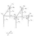
도 5는, 실시 형태의 평면도 측정 방법에 있어서, 각 측정 데이터로부터 평면도를 산출하는 연산 처리의 주요부에 대해서 나타낸 사시 개략도이다. 도 5에서는, 최초의 3점 측정 단계에 있어서 얻어진 측정 데이터의 처리에 대해서 나타내고 있다. Fig. 5 is a perspective schematic diagram showing the main parts of a calculation process for calculating a plan view from each measurement data in the plan view measurement method of the embodiment. In FIG. 5, processing of the measurement data obtained in the first three-point measurement step is shown.
도 5에 있어서, 각 핀 P11, P21, P12의 상단의 높이를 H11, H21, H12로 한다. 높이는, 기준이 되는 수평면이 필요한데, 예를 들면 베이스반(2)의 상면으로 할 수 있다. 도 5에서는, 핀 P12의 높이 H12가 가장 높고, 핀 P21의 높이가 가장 낮아져 있지만, 이것은 측정 결과의 일례이다. In FIG. 5, the heights of the upper ends of the pins P 11 , P 21 , and P 12 are H 11 , H 21 , and H 12 . The height requires a horizontal surface as a reference, and can be, for example, an upper surface of the
지금, 핀 P11의 높이 H11을 기준으로 하고, 그것보다 높은 경우의 높이의 차이를 양, 그것보다 낮은 경우의 높이의 차이를 음으로 한다. 이 경우, 핀 P21은 핀 P11에 대해 X방향의 동일 직선 상에 있으며, 핀 P12는 핀 P11에 대해 Y방향의 동일 직선 상에 있으므로, 각 차이는 이하의 식 1, 식 2로 표시된다. Now, the pin relative to the height of the P 11 H 11, and the amount of the difference in height is higher than that, a negative difference in height of lower than it. In this case, since pin P 21 is on the same straight line in the X direction with respect to pin P 11 and pin P 12 is on the same straight line in the Y direction with respect to pin P 11 , each difference is expressed by the following

식 1에 있어서, dH1은, H11에 대한 H21의 차이, dH2는 H11에 대한 H21의 차이이다. θxi는 X방향의 기울기각, θY1은 Y방향의 기울기각이며, 각각 당해 3점 측정 단계에서의 측정 데이터이다. w는, 각 핀의 XY방향의 이격 간격이다. In the
기울기각의 양음에 대해서 설명하면, 도 5에 있어서, 핀 P11을 원점으로 하고, 도 3의 종이면상 우측을 향하는 X방향을 +측으로 하여, 이것을 기준으로 한 반시계 방향을 X방향의 기울기각에 있어서의 양의 각도로 한다. Y방향에 대해서도, 핀 P11을 원점으로 하고, 도 3의 종이면상 비스듬한 상측으로 향하는 Y방향을 +측으로 하여, 이것을 기준으로 한 반시계 방향 Y방향의 기울기각에 있어서의 양의 각도로 한다. When the positive and negative of the tilt angle is described, in FIG. 5, the pin P 11 is used as the origin, the X direction toward the right side on the paper plane of FIG. 3 is set to the + side, and the counterclockwise direction based on this is the tilt angle in the X direction. Let it be a positive angle in. Also in the Y direction, the pin P 11 is used as the origin, and the Y direction directed toward the oblique upper side on the paper plane in FIG. 3 is set to the + side, and is set as a positive angle in the inclined angle in the counterclockwise Y direction based on this.
이와 같이 하여, 높이 H11에 대한 높이 H21의 차이, 높이 H12의 차이가 각각 산출된다. In this way, the difference in height H 21 with respect to the height H 11 and the difference in height H 12 are respectively calculated.
다음에, 그 이웃하는 3개의 핀 P21, P31, P22의 측정 데이터에 대해서 검토한다. 이 경우도, 높이 H21에 대한 높이 H31의 차이, 높이 H21에 대한 높이 H22의 차이가 식 3, 식 4에 의해 각각 산출된다. Next, the measurement data of the three adjacent pins P 21 , P 31 , and P 22 are examined. Also in this case, the difference of the height H 31 with respect to the height H 21 and the difference of the height H 22 with respect to the height H 21 are computed by
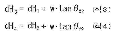
식 3, 식 4에 있어서, dH3은 H21에 대한 H31의 차이, dH4는 H21에 대한 H22의 차이이다. 동일하게, θX2는 X방향의 기울기각의 측정 데이터, θY2는 Y방향의 기울기각의 측정 데이터이다. 식 3, 식 4에 대해, 식 1, 식 2의 산출 결과를 대입하면, 2회째의 3점 측정 단계에서 측정한 2개의 핀 P31, P22의 높이 H31, H22의 높이 H11에 대한 차이가 구해진다. In
이후, 설명은 생략하지만, 3회째의 3점 측정 단계에서의 측정 데이터에 의해 핀 P41, 핀 P32의 높이의 높이 H11에 대한 차이가 구해지고, 4회째의 3점 측정 단계에서의 측정 데이터에 의해 핀 P51, 핀 P42의 높이의 높이 H11에 대한 차이가 구해진다. Thereafter, although the description is omitted, the difference in height H 11 of the heights of the pins P 41 and P 32 is determined by the measurement data in the third three-point measurement step, and the measurement in the fourth three-point measurement step is obtained. The difference between the heights H 11 of the heights of the pins P 51 and P 42 is obtained from the data.
이와 같이 하여, 산출 결과를 다음의 3점 측정 단계에서의 측정 데이터에 대입하여 적용함으로써, 모든 핀의 높이에 대해서, 좌측 아래의 핀 P11의 높이 H11에 대한 차이가 구해지게 된다. In this way, by substituting and applying the calculation result to the measurement data in the next three-point measurement step, the difference of the height H 11 of the pin P 11 in the lower left is obtained for all the pin heights.
그렇게 하면, 모든 핀 중에서, 상단의 위치가 가장 높은 핀과, 가장 낮은 핀을 특정할 수 있게 되어, 양자의 높이의 차이를 가지고, 평면도의 측정 결과로 할 수 있다. Then, among all the pins, the pin with the highest position and the lowest pin can be specified, and the difference between the heights of the pins can be used to make the measurement result of the plan view.
또한, 상기 각 측정 데이터의 처리에 있어서, 마지막 3점 측정 단계에서의 측정 데이터에 대해서는, 측정 유닛(4)의 방향을 반대로 하여 측정하고 있으므로, X방향, Y방향 각각에 대해서 양음을 반대로 하여 기울기각의 양음을 판단한다. In addition, in the processing of each measurement data, since the measurement data in the last three-point measurement step is measured by reversing the direction of the
연산 처리 단계에 대해서, 보다 구체적인 예를 설명하면, 상술한 바와 같은 연산은, 이른바 표계산 소프트웨어를 사용함으로써 간편하게 행할 수 있다. 이 점에 대해서, 도 6을 사용하여 일례를 설명한다. 도 6은, 표계산 소프트웨어에 의한 연산 처리 단계의 실행예를 개략적으로 나타낸 도이다. When a more specific example is explained with respect to the calculation processing step, the calculation as described above can be easily performed by using so-called surface calculation software. An example of this will be described with reference to FIG. 6. 6 is a diagram schematically showing an example of execution of the calculation processing step by the table calculation software.
도 6에 있어서, 어느 셀열 A에는, 3점 측정 단계의 번호가 입력되고, 어느 셀열 B에는, 대응하는 3점 측정 단계의 측정 데이터 중, X방향의 기울기각이 입력되고, 다른 셀열 C에는, Y방향의 기울기각이 입력된다. In FIG. 6, the number of the three-point measurement step is input to one cell column A, and the inclination angle in the X direction is input from the measurement data of the corresponding three-point measurement step to the other cell column B, and to the other cell column C, The tilt angle in the Y direction is input.
그리고, 또한 다른 셀열 D~F에는, 당해 3점 측정 단계에서의 측정 데이터에 따라서 산출된 각 핀 높이(엄밀하게는 높이의 차이)가 입력된다. 도 6에서는, 각 3점 측정 단계에 있어서 직각 이등변 삼각형에 있어서의 꼭지각(90도의 각)에 위치한 핀을 「삼각 원점 핀」으로 부르고 있으며, 셀열 D는 그 핀의 상단의 높이가 입력된다. 또, 삼각 원점 핀에 대해 X방향에 위치하고 있는 핀을 「X방향 핀」으로 부르고 있으며, 셀열 E에는, 그 핀의 상단의 높이가 입력된다. 또한, 삼각 원점 핀에 대해 Y방향에 위치하고 있는 핀을 「Y방향 핀」으로 부르고 있으며, 셀열 F에는 그 핀의 상단의 높이가 입력된다. In addition, the pin heights (strictly, the difference in height) calculated according to the measurement data in the three-point measurement step are input to other cell columns D to F. In Fig. 6, the pin located at the apex angle (angle of 90 degrees) in a right-angled isosceles triangle in each three-point measurement step is called a "triangular origin pin", and the height of the top of the pin is input to the cell column D. Moreover, the pin located in the X direction with respect to the triangular origin pin is called a "X direction pin", and the height of the upper end of the pin is input to the cell string E. In addition, the pin located in the Y direction with respect to the triangular origin pin is called a "Y direction pin", and the height of the top of the pin is input to the cell column F.
보다 구체적으로는, 도 6의 예에서는, 셀 D2에 핀 P11의 높이(=0)가 입력되고, 셀 E2에는 핀 P21의 높이가 입력되고, 셀 F2에는 핀 P12의 높이가 입력된다. 셀 E2는 셀 B2의 측정 데이터를 식 1에 적용하여 계산한 값(끼워넣기 계산의 결과)이며, 셀 F2는, 셀 C2의 측정 데이터를 식 2에 적용하여 계산한 값이다. 이러한 계산이 자동적으로 되도록, 셀 E2, F2에는 계산식이 미리 입력된다. More specifically, in the example of FIG. 6, the height of the pin P 11 (=0) is input to the cell D2, the height of the pin P 21 is input to the cell E2, and the height of the pin P 12 is input to the cell F2. . Cell E2 is a value calculated by applying the measurement data of cell B2 to Equation 1 (the result of the interpolation calculation), and cell F2 is a value calculated by applying the measurement data of cell C2 to
3번 셀행에는, 2회째의 3점 측정 단계에서의 측정 데이터가 입력되어 계산된다. 이 경우, 셀 D3에 핀 P21의 높이가 입력되기 때문에, 셀 E2의 값이 계산식마다 그대로 카피되도록 셀의 링크가 설정된다. 셀 E3에는 핀 P31의 높이가 입력되고, 셀 F3에는 핀 P22의 높이가 입력된다. 셀 E3은 셀 B3의 측정 데이터를 식 1에 적용하여 계산한 값(끼워넣기 계산의 결과)이며, 셀 F3은, 셀 C3의 측정 데이터를 식 2에 적용하여 계산한 값이다. 이러한 계산이 자동적으로 되도록, 링크나 계산식이 미리 설정된다. 또한, 도 6은, 각 핀(3)의 이격 거리 w가 100mm인 경우의 예로 하고 있다. In the third cell row, measurement data in the second three-point measurement step is input and calculated. In this case, since the height of the pin P 21 is input to the cell D3, the link of the cell is set so that the value of the cell E2 is copied for each calculation formula. The height of the pin P 31 is input to the cell E3, and the height of the pin P 22 is input to the cell F3. Cell E3 is a value calculated by applying the measurement data of cell B3 to Equation 1 (the result of the interpolation calculation), and cell F3 is a value calculated by applying the measurement data of cell C3 to
이후, 설명은 생략하지만, 각 행의 셀에 대해서, 동일하게 링크나 계산식이 미리 설정되어 있어, 셀열 B와 셀열 C에 측정 데이터가 입력되면, 셀열 D~F의 각 셀의 링크나 계산이 갱신되어, 각 핀 높이의 차이가 자동 계산된다. Hereinafter, although the description is omitted, the link or calculation formula is set in the same way for the cells in each row, and when measurement data is input to the cell columns B and C, the link or calculation of each cell in the cell columns D to F is updated. The difference in height of each pin is automatically calculated.
또한, 마지막 3점 측정 단계에서의 측정 데이터에 있어서, 핀 Pmn의 높이의 산출에 대해서는, 핀 Pm(n-1)의 높이를 기준으로 하여 산출해도 되고, 핀 P(m-1)n의 높이를 기준으로 하여 산출해도 되고, 어느 한쪽을 미리 설정해 둔다. In addition, in the measurement data at the last three-point measurement step, the calculation of the height of the pin P mn may be calculated based on the height of the pin P m(n-1) , or the pin P (m-1) n You may calculate based on the height of, and either one is previously set.
이와 같이 표계산 소프트웨어를 사용한 연산 처리에 있어서, 각 셀에 대해 링크나 계산식을 적당히 설정해 둠으로써, 모든 핀(3)의 상단의 높이가 좌측 아래의 핀 P11을 기준으로 하여 구해지며, 상단의 최고값과 최저값의 차가 평면도로서 구해진다. In the calculation processing using the table calculation software in this way, by setting the link or calculation formula appropriately for each cell, the height of the top of all the
또한, 측정 데이터는, 수준기(6)의 수신부로부터 USB를 통하여 연산 처리 유닛(7)에 보내지는데, 셀열 B와 셀열 C에 순차적으로 측정 데이터가 입력되도록 표계산 소프트웨어에 있어서 매크로 프로그램이 적당히 설치되면 적합하다. 즉, 측정 데이터를 수신하면 X방향의 기울기각을 셀열 B의 액티브한 셀에 입력하고, Y방향의 기울기각을 셀열 C의 액티브한 셀에 입력한 후, 하나 아래의 행의 셀열 B와 셀열 C를 액티브로 하는 매크로 프로그램이 설치된다. In addition, the measurement data is sent from the receiver of the
상술한 실시 형태의 평면도 측정 방법에 의하면, 다수의 핀(3)의 상단이 이루는 가상면의 평면도를 간편하게 측정할 수 있다. 측정에 사용하는 툴에 대해서도, 수준기(6)와 측정판(5)을 조합한 심플한 것이므로, 저비용으로 실현할 수 있다. 이 때문에, 극히 실용적인 측정 방법이 된다. According to the plan view measuring method of the above-described embodiment, the plan view of the virtual surface formed by the upper ends of the plurality of
상기 실시 형태의 평면도 측정 방법에 있어서, 각 3개의 핀(3)을 선택해 나가는 순서에 대해서는, 상술한 것 이외의 경우도 있을 수 있다. 가장 아래의 열에 대해 측정을 행한 후, 아래로부터 2열째에 대해서는 좌측 끝으로 돌아와 같은 방향으로 순차적으로 측정 유닛(4)을 이동시켜도 된다. 따라서, 중복된 핀이 직전의 3점 측정 단계에서 선택한 핀이 아닌 경우도 있다. 중요한 것은, 어느 3개의 핀(3)의 조에 대한 측정인지 틀리지 않도록 하는 것이며, 미리 정한 순서로 각 3개의 핀(3)의 조를 선택하여 모두 핀(3)에 대해서 측정을 행하는 것이다. In the plan view measuring method of the above-described embodiment, the procedure of selecting each of the three
상기의 관점에서는, 항상 2개의 핀(3)이 중복해서 선택되도록 하는 것도 가능하지만, 연산이 복잡해지기 쉽기 때문에, 중복되는 갯수가 한개뿐인 3점 측정 단계를 가능한 한 많게 하는 패턴으로 하는 것이 바람직하다. 또한, 상기의 예에서는, 중복해서 상단의 높이의 계산이 행해지는 핀(3)이 상당수 있지만, 덮어쓰기하여 계산해도 되고, 최초의 계산 결과를 유지하도록 해도 된다. From the above point of view, it is possible to always select the two
상기 설명에서는, 측정 유닛(4)을 작업자가 손으로 집어 각 위치에 배치하도록 설명했지만, 로봇 등으로 자동화하는 경우도 있을 수 있다. 예를 들면, 측정 유닛(4)의 배치의 위치 및 그 루틴을 로봇에 대해 티칭하여 행하게 하는 경우도 있을 수 있다. In the above description, the
또, 측정 유닛(4)에 대해서는, 2축식의 수준기가 바람직하지만, 1축식으로도 실시는 가능하다. 1축식인 경우에는, 수준기(6)를 측정판(5) 상에서 90도 방향을 변경할 수 있도록 구성한다. 그리고, 각 3개의 핀(3)에 대해 수준기(6)의 방향을 90도 변경한 2회의 측정을 행하게 된다. 또한, 연산 처리 유닛(7)은, 수준기(6)가 내장되어 있거나, 수준기(6)에 부설되어 있는 구조도 생각할 수 있어, 연산 처리 유닛(7)은, 수준기(6)와는 따로 설치되지 않은 경우도 있을 수 있다. 또한, 연산 처리 유닛(7)이, 노광 장치와 같은 기판 처리 장치의 일부로서 설치되는 경우도 있다. Moreover, about the
측정판(5)의 형상으로서는, 삼각형 이외에도 L자 등의 다른 형상도 생각할 수 있다. 단, 수준기(6)를 고정하는 스페이스가 필요한 것, 측정판(5)의 중심 위치에 수준기(6)가 고정되지 않으면, 측정판(5)의 부상(어느 하나의 핀(3)의 상단으로부터 떨어져 버리는 것)이 생기기 쉬운 것 등으로부터, 삼각형이 바람직하다. As the shape of the measuring
또, 4개의 핀(3)에 대해 측정 유닛(4)이 올려지는 상태로 하여 측정하는 것도 생각할 수 있어, 이론적으로는 평면도의 산출도 가능하지만, 측정판(5)이 4개의 핀(3)의 상단 모두에 접촉한 상태로 하는 것은 어려운 것이나 연산 처리가 복잡해지기 때문에, 3개의 핀(3)에 측정 유닛(4)이 올려지는 구조가 바람직하다. It is also possible to measure the four
또한, 상기 설명에서는, 수준기(6)에 있어서의 2축과 핀(3)의 배열 방향의 XY는 일치하고 있는 것으로 설명했지만, 일치하고 있지 않아도 그 어긋남을 이미 알고 있으면 측정은 가능하다. 수준기(6)에 있어서의 측정 방향과 핀(3)의 배열 방향의 어긋남각에 따라 평면에서 보았을 때의 보정을 한 다음 상기 연산 처리를 적용하면 된다. 단, 수준기(6)에 있어서의 2축과 핀(3)의 배열 방향이 일치하는 것이 연산 처리는 간이해진다. In addition, in the above description, although the XY in the arrangement direction of the two axes in the
다음에, 핀 높이 조정 방법의 발명의 실시 형태에 대해서 설명한다. 도 7은, 실시 형태에 관련된 핀 높이 조정 방법을 나타낸 정면 개략도이다. Next, an embodiment of the invention of the pin height adjustment method will be described. 7 is a front schematic diagram showing a pin height adjustment method according to an embodiment.
실시 형태의 핀 높이 조정 방법은, 상술한 실시 형태의 평면도 측정 방법을 이용한 것이다. 즉, 상술한 바와 같이 평면도를 측정한 후, 측정 결과에 따라 각 핀(3)의 돌출 높이를 조정함으로써 각 핀(3)의 상단의 높이의 차이를 일정 범위 내로 억제해 가는 것이다. The pin height adjustment method of the embodiment uses the plan view measurement method of the above-described embodiment. That is, after measuring the plan view as described above, by adjusting the protruding height of each
이 실시 형태에서는, 각 핀(3)의 돌출 높이의 조정을 위해, 심(정밀 스페이서)(8)을 사용한다. 심(8)은, 두께가 높은 정밀도로 이미 알려진 예를 들면 원환형의 부재이다. 상술한 바와 같이, 각 핀(3)은 베이스반(2)에 대해 나사식 삽입으로 고정되어 있는데, 각 핀(3)의 하단의 나사 절삭부는, 심(8)의 중앙 개구보다 가늘고, 나사 절삭부보다 상측의 몸통부는, 심(8)의 중앙 개구보다 작다. 따라서, 각 핀(3)은 심(8)을 끼워넣은 상태로 베이스반(2)에 대해 나사식 삽입할 수 있다. 심(8)의 종류(두께) 및 장수를 적절히 선택함으로써, 베이스반(2)으로부터의 핀(3)의 돌출 높이가 조정된다. In this embodiment, a shim (precision spacer) 8 is used for adjustment of the protruding height of each
실시 형태의 핀 높이 조정 방법에서는, 상술한 평면도 측정 방법을 실시하여, 특정의 핀(3)(상기의 예에서는 핀 P11)를 기준으로 하여 상단의 높이의 차이를 측정한다. 다음에, 가장 상단의 높이가 높은 핀(3)을 기준으로 하여 차이를 다시 계산한다. 차이는, 모두 음의 값이 되기 때문에, 그에 따라(차가 제로가 되도록), 심(8)의 종류 및 장수를 선택한다. 이 때, 차이에 딱 맞는 심(8)의 조합이 없는 경우가 많아, 그 경우는 가장 가까운(근사한) 심(8)의 조합을 선택한다. In the pin height adjustment method of the embodiment, the above-described flatness measurement method is performed, and the difference in height at the top is measured based on the specific pin 3 (pin P 11 in the above example). Next, the difference is recalculated based on the
예를 들면, 어느 핀(3)의 높이의 차이가 -69μm이며, 두께 1Oμm의 심(8)과 두께 50μm의 심(8)이 있는 경우에, 10μm의 심(8)을 2장, 50μm의 심(8)을 1장 준비하고, 그들을 겹쳐 끼워 넣음으로써, 당해 핀(3)을 베이스반(2)에 나사식 삽입한다. 이와 같이 하여 가장 높은 핀(3)에 상단의 위치가 맞도록, 다른 모든 핀(3)에 대해서 차이 만큼의 심(8)을 끼워 넣으면서 핀(3)을 다시 삽입한다. For example, if the difference in height of a
실시 형태의 방법에서는, 이와 같이 하여 높이를 조정한 후, 평면도를 한번 더 측정한다. 즉, 측정 유닛(4)을 각 3개의 핀(3) 상에 순차적으로 재치(載置)하고, 각 3점 측정 단계를 행한다. 그리고, 얻어진 측정 결과, 즉 각 핀(3)의 상단의 높이의 차이를 확인한다. 이 경우, 높이의 차이가 일정 범위에 들어가 있으면, 이것으로 조정은 종료되지만, 대부분의 경우, 일정 범위에 들어가 있지 않다. 일정 범위란, 평면도의 요구 정밀도이며, 핀(3)의 상단의 높이의 차이가 어느 정도까지 허용되는가에 관한 것이다. 일정 범위에 들어가지 않는 이유는, 최초의 측정 시의 오차, 근사한 심(8)의 선택에 의한 영향, 심(8)의 두께의 미소한 편차, 조정 후에 나사식 삽입 시의 삽입 깊이의 편차 등이다. 이들이 서로 작용하여 결과적으로 상단의 높이에 편차가 생겨 버리는 경우가 많다. In the method of the embodiment, after adjusting the height in this way, the plan view is measured once more. That is, the
어쨌든, 일정 범위에 들어가 있지 않으면, 재차 조정을 한다. 재차 조정에서는, 심(8)을 제거하거나 추가하거나 하여, 필요 최소한의 조정으로 하는 것이 바람직하다. 즉, 각 핀(3)의 상단의 높이의 평균값을 산출하고, 그것을 기준으로 하여 플러스 마이너스의 조정량을 산출한다. 그리고, 플러스의 조정량이면, 그에 가장 근사한 심(8)의 종류와 장수를 판단하여 추가한다. 마이너스의 조정량이면, 그에 가장 근사한 종류의 장수의 심(8)을 제거한다. Anyway, if it is not within a certain range, it is adjusted again. In the adjustment again, it is preferable to remove or add the
그리고, 한번 더 평탄도를 측정하여, 일정 범위에 들어가 있으면, 조정 종료로 한다. 들어가 있지 않으면, 재차, 심(8)을 빼고 끼워 조정하고, 일정 범위에 들어갈 때까지 측정과 조정을 반복한다. 통상은, 2~3회 정도의 측정과 빼고 끼우기로 조정은 완료된다. Then, the flatness is measured once more, and if it is within a certain range, the adjustment is terminated. If not, remove the
실시 형태의 핀 높이 조정 방법에 의하면, 측정 유닛(4)을 사용하여 3점 측정 단계를 반복함으로써 평면도를 측정하고, 이것에 의거하여 핀 높이를 조정하므로, 간편한 절차로 측정 결과를 얻어 조정을 행할 수 있다. 이 때문에, 측정과 조정을 반복하는 경우에도, 수고가 들지 않고, 번잡해지지 않는다. According to the pin height adjustment method of the embodiment, the flatness is measured by repeating the three-point measurement step using the
또, 심(8)을 사용하므로, 각 핀(3)의 돌출 높이의 조정을 간편하고 확실히 행할 수 있다. 다른 방법으로서, 각 핀(3)의 삽입 깊이를 조정해도 된다. Moreover, since the
또한, 측정과 조정을 반복하는 상기 실시 형태의 방법은, 특히 높은 평면도가 요구되는 경우에 적합하게 채용된다. Moreover, the method of the said embodiment which repeats a measurement and adjustment is employ|adopted suitably especially when a high planarity is calculated|required.
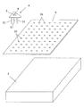
다음에, 제2 실시 형태의 평면도 측정 방법에 대해서 설명한다. 도 8은, 제2 실시 형태의 평면도 측정의 개략을 나타낸 사시도이다. Next, a method of measuring a plan view of the second embodiment will be described. 8 is a perspective view showing an outline of a plan view measurement of the second embodiment.
제1 실시 형태는, 다수의 핀(3)의 상단이 이루는 가상면의 평면도를 측정하는 방법이였지만, 제2 실시 형태는, 물체의 표면(실제의 면)의 평면도를 측정하는 방법으로 되어 있다. 이 방법은, 예를 들면 상술한 베이스반(2)과 같은 기계 구조적으로 기준이 되는 수평면을 제공하는 부재의 상면의 평면도를 측정할 때에 적합하게 행해진다. The first embodiment was a method of measuring the planar view of the virtual surface formed by the upper ends of the plurality of
제2 실시 형태에서 사용되는 측정 유닛(4)은, 제1 실시 형태와 조금 상이하다. 즉, 이 방법에서 사용되는 측정 유닛(4)은, 도 8에 나타내는 바와 같이, 측정판(5)의 상면에 수준기(6)가 고정되고, 측정판(5)의 하면으로부터 3개의 다리 핀(51)이 수직으로 하방으로 연장된 구성으로 되어 있다. The
측정판(5)은, 적어도 상면이 평탄한 면으로 되어 있다. 평탄성은, 측정하는 평면도의 정밀도와의 관계로 규정된다. At least the upper surface of the measuring
측정판(5)은, 동일하게 삼각형상(여기에서는 직각 이등변 삼각형상)이며, 수준기(6)는, 측정판(5)의 중앙에 고정되어 있다. 수준기(6)로서는, 동일하게 디지털 무선식의 2축 수준기가 적합하게 사용된다. The measuring
하방으로 연장되는 3개의 다리 핀(51)은, 적어도 측정판(5)의 상면으로부터의 길이가 균일한 것이 필요하다. 전형적으로는, 측정판(5)의 하면을 상면과 동일하게 평탄한 면으로 하고, 측정판(5)의 두께를 균일한 것으로 함과 함께, 다리 핀(51)의 길이를 모두 동일하게 함으로써 달성된다. It is necessary that the three
한편, 측정 대상인 물체는, 표면에 측정점 마크를 구비하고 있다. 실시 형태의 방법은 측정 유닛(4)을 물체의 상면에 올리고 측정하는데, 측정점 마크는 그 때의 표시이다. 마크를 물체의 상면에 직접 설치하는 것이 어려운 경우가 많기 때문에, 이 실시 형태에서는, 측정 시트(9)를 물체의 상면에 씌우도록 하고, 측정 시트(9)에 측정점 마크(91)를 설치하고 있다. On the other hand, the object to be measured has a measurement point mark on its surface. In the method of the embodiment, the
측정 시트(9)는, 필름형 또는 얇은 판형이며, 플렉서블한 것이 아닌 경우도 있을 수 있다. 측정점 마크(91)는, 이 예에서는 측정 시트(9)에 설치한 오목부로 되어 있다. 예를 들면, 얇은 금속의 판을 정밀도 있게 절삭 가공하고, 측정점 마크(91)로서의 오목부를 형성하는 것을 생각할 수 있다. The measurement sheet 9 is a film or thin plate, and may not be flexible. The
측정점 마크(91)는, 그 위에 측정 유닛(4)의 각 다리 핀(51)이 올려지는 위치로서 설치되어 있다. 따라서, 측정점 마크(91)는, 3개의 다리 핀(51)의 배치 간격과 같은 간격으로 다수 설치되어 있다. 도 8의 예에서는, 3개의 다리 핀(51)은, 직각 이등변 삼각형의 꼭지점에 상당하는 위치에 설치되어 있으므로, 측정점 마크(91)는, 직각 격자의 교점에 상당하는 위치에 각각 설치되어 있다. 각 측정점 마크(91)의 종횡의 이격 거리(오목부의 중심 간의 거리)는, 3개의 다리 핀(51)의 배치 간격과 같다. The
각 측정점 마크(91)로서의 오목부의 깊이는, 정밀도 있게 균일한 것으로 되어 있다. 오목부의 개구는, 다리 핀(51)의 굵기보다 조금 큰 정도이다. 또한, 각 다리 핀(51)의 하단을 원뿔형으로 하고, 각 측정점 마크(91)를 피봇형(유발형)으로 하는 경우가 있다. The depth of the concave portion as each
**
*물체의 평면도를 측정하는 절차로서는, 기본적으로 제1 실시 형태와 동일하다. 예를 들면, 처음에 좌측 아래의 3개의 측정점 마크(91)에 다리 핀(51)의 하단이 들어가도록 하여 측정 유닛(4)을 물체의 상면에 재치한다. 이 상태로 3점 측정 단계를 행한다. 즉, 수준기(6)를 동작시켜, 그 측정 데이터를 무선 경유로 연산 처리 유닛(7)에 보낸다. 다음에, 하나 우측의 3개의 측정점 마크(91)에 다리 핀(51)의 하단이 들어가도록 하여 측정 유닛(4)을 재치하고, 동일하게 측정한다. 이후, 도 4에 나타내는 것과 동일하게 지그재그형으로 측정점 유닛을 시프트시키는 방향을 바꾸면서, 모든 측정점 마크(91)에 대해서 측정을 행한다. 그리고, 우측 위의 측정점 마크(91)에 대해서는, 측정 유닛(4)의 방향을 180도 바꾸고 측정을 행한다. * The procedure for measuring the flatness of the object is basically the same as in the first embodiment. For example, the
이와 같이 하여 각 3점 측정 단계에서 얻어진 측정 데이터를 연산 처리하여, 물체의 상면의 평면도를 산출한다. 연산 처리에 대해서도, 기본적으로 제1 실시 형태와 동일하다. 이 실시 형태에서는, 측정점 마크(91)의 배치 간격(즉 다리 핀(51)의 배치 간격)이 상수(이미 알고 있는 값)가 되고, 그것을 편입한 형태로 연산 처리가 되어 평면도가 측정된다. In this way, the measurement data obtained in each of the three-point measurement steps are subjected to arithmetic processing to calculate the top view of the upper surface of the object. The calculation processing is also basically the same as in the first embodiment. In this embodiment, the arrangement interval of the measurement point mark 91 (that is, the arrangement interval of the leg pins 51) becomes a constant (a value that is already known), and calculation processing is performed in the form of incorporation thereof to measure the flatness.
또한, 이 실시 형태에 있어서의 평면도는, 각 측정점 마크(91)의 바로 아래의 지점의 높이의 차이로서 표시되며, 표면 거칠기와 동일 취지라고도 말할 수 있다. In addition, the plan view in this embodiment is displayed as the difference in the height of the point immediately below each
이 실시 형태의 평면도 측정 방법은, 예를 들면, 베이스반(2)을 제작했을 때, 그 상면의 거칠기를 체크할 때에 적합하게 행해진다. 또, 베이스반(2)에 대해 기구 부분을 만들어 어떠한 장치를 구성하고, 어느 정도의 기간 사용하면, 베이스반(2)이 열화되어 상면에 만곡 등이 생기는 일이 있는데, 이와 같은 베이스반(2)의 열화를 체크할 때에도 적합하게 행해진다. The flatness measurement method of this embodiment is suitably performed, for example, when manufacturing the
이 실시 형태에 있어서, 「다리 핀」의 용어는 널리 해석된다. 다리 핀(51)은, 측정판(5)의 상면에 대해 일정한 거리를 확보하기 위한 것이기 때문에, 반드시 「핀」이라고 부를 수 있는 것일 필요는 없고, 예를 들면 반구형과 같은 돌기여도 된다. In this embodiment, the term "leg pin" is widely interpreted. Since the leg pins 51 are for securing a certain distance to the upper surface of the measuring
또, 측정점 마크는, 반드시 오목부일 필요는 없고, 인쇄 등의 방법으로 형성된 단순한 마크여도 된다. 단, 오목부에 다리 핀(51)을 끼워 넣는 구조가, 측정 유닛(4)을 정밀도 있게 배치하는 것이 용이하므로 적합하다. 또한, 측정점 마크가 물체의 상면에 직접 설치되는 경우도 있다. Moreover, the measurement point mark does not necessarily need to be a recess, and may be a simple mark formed by a method such as printing. However, the structure in which the
또한, 각 3점 측정 단계의 측정 결과로부터 평면도를 산출하는 연산 처리에 대해서는, 소프트웨어에 의해 또는 하드웨어에 의해 자동적으로 행해지는 경우 만이 아니라, 작업자가 손 계산으로 행하는 경우도 있을 수 있다. 핀의 수가 적은 경우에는, 그 쪽이 간편한 경우도 있을 수 있다. In addition, the calculation process for calculating the flatness from the measurement result of each three-point measurement step may be performed by the operator by hand calculation, not only by software or by hardware. When the number of pins is small, there may be cases where it is convenient.
또한, 상기 각 방법에 있어서, 핀(3)이나 측정점 마크(91)의 배치는 이미 알고 있으면 되며, 바둑판의 눈금형이 아니여도 된다. 예를 들면, X방향과 Y방향에서 이격 거리가 상이해도 된다. 이 경우, X방향의 이격 거리 w1과 Y방향의 이격 거리 w2가 상이한 상수로서 부여될 뿐이며, 그 외에는 동일하게 행할 수 있다. 또한, 직각 격자의 교점이 아닌 경우여도 되고, 예를 들면 마름모꼴의 격자형이어도 된다. 이 경우는, 그 격자의 각도가 상수로서 부여되며, 수준기(6)의 측정 방향에 대한 각도로 보정을 한 다음 연산 처리가 되어, 평면도가 측정된다. In addition, in each of the above methods, the arrangement of the
또, 각 방법이 적용되는 장치로서는, 상술한 노광 장치 외에, 광배향 장치와 같은 다른 장치도 있을 수 있다. Moreover, as an apparatus to which each method is applied, there may be other apparatuses, such as a photo-alignment apparatus, in addition to the above-described exposure apparatus.
1 핀 유닛
2 베이스반
3 핀
4 측정 유닛
5 측정판
51 다리 핀
6 수준기
61 송신부
62 수신부
7 연산 처리 유닛
8 심
9 측정 시트
91 측정점 마크1
3
5 Measuring
6
62
8 core 9 measurement sheet
91 measuring point mark
Claims (1)
평탄한 상면을 가지는 측정판과, 측정판 상에 부착된 수준기와, 측정판의 하면으로부터 하방으로 수직으로 연장되며, 측정판의 상면으로부터의 길이가 균일한 3개의 다리 핀을 구비한 측정 유닛을 사용하는 방법이며,
다수의 측정점 마크의 배치는, 서로 이웃하는 어느 3개의 측정점 마크를 선택한 경우에도 측정 유닛의 3개의 다리 핀의 배치와 동일해지는 배치이며,
다수의 측정점 마크 중 서로 이웃하는 3개의 측정점 마크를 선택하고, 선택된 3개의 측정점 마크 상에 측정 유닛의 다리 핀이 각각 올려지는 상태로, 직교하는 2개의 수평 방향에 있어서의 측정판의 기울기를 수준기에 의해 측정하는 3점 측정 단계를 포함하는 방법이며,
3점 측정 단계를, 각 3개의 측정점 마크에 대해 순차적으로 행함으로써 평면도를 측정하는 방법이며,
2회째 이후의 3점 측정 단계는, 그때까지 선택된 측정점 마크 중 한개를 중복해서 선택하여 측정을 행하는 단계이며, - 상기 중복해서 선택된 측정점 마크는 직전의 3점 측정 단계에서 선택한 측정점 마크 이외의 측정점 마크라도 됨 -
3점 측정 단계를 순차적으로 행함으로써 모든 측정점 마크에 대해서 수준기에 의한 측정판의 상면의 기울기를 측정하는 방법이며,
각 3점 측정 단계에 있어서의 상기 2개의 수평 방향의 측정판의 상면의 기울기로부터, 가장 높은 위치에 있는 측정점 마크와 가장 낮은 위치에 있는 측정점 마크의 높이의 차이를 산출하는 단계를 포함하는 것을 특징으로 하는 평면도 측정 방법.A flatness measuring method for covering a top surface of an object with a measurement sheet having a plurality of measurement point marks already known in a horizontal arrangement, and measuring a flatness in the horizontal direction of the top surface of the object,
A measuring unit having a flat upper surface, a level attached to the measuring board, and vertically extending downwardly from the lower surface of the measuring board, and a measuring unit having three leg pins of uniform length from the upper surface of the measuring board are used. How to do it,
The arrangement of the multiple measurement point marks is the same as the arrangement of the three leg pins of the measurement unit even when any three measurement point marks adjacent to each other are selected,
Among the multiple measurement point marks, three measurement point marks that are adjacent to each other are selected, and the level of the inclination of the measurement plate in two orthogonal two horizontal directions is leveled, with the leg pins of the measurement unit raised on the three selected measurement point marks. Method comprising a three-point measuring step to measure by,
It is a method of measuring a plan view by sequentially performing a three-point measuring step for each of the three measuring point marks,
The second and subsequent three-point measurement step is a step of repeatedly selecting and measuring one of the selected measurement point marks, and the measurement point mark selected above is a measurement point mark other than the measurement point mark selected in the previous three-point measurement step. May be-
It is a method to measure the inclination of the upper surface of the measuring plate by the level for all the measuring point marks by sequentially performing the three-point measuring step.
And calculating the difference between the height of the measurement point mark at the highest position and the measurement point mark at the lowest position from the inclination of the upper surfaces of the two horizontal measurement plates in each three-point measurement step. Floor plan measurement method.
Applications Claiming Priority (4)
| Application Number | Priority Date | Filing Date | Title |
|---|---|---|---|
| JPJP-P-2017-060268 | 2017-03-26 | ||
| JP2017060268A JP6392395B1 (en) | 2017-03-26 | 2017-03-26 | Flatness measurement method and pin height adjustment method |
| PCT/JP2018/006307 WO2018180047A1 (en) | 2017-03-26 | 2018-02-21 | Flatness measurement method and pin-height adjustment method |
| KR1020197021073A KR20190094447A (en) | 2017-03-26 | 2018-02-21 | Flatness measurement method and pin-height adjustment method |
Related Parent Applications (1)
| Application Number | Title | Priority Date | Filing Date |
|---|---|---|---|
| KR1020197021073A Division KR20190094447A (en) | 2017-03-26 | 2018-02-21 | Flatness measurement method and pin-height adjustment method |
Publications (2)
| Publication Number | Publication Date |
|---|---|
| KR20200083669A true KR20200083669A (en) | 2020-07-08 |
| KR102337802B1 KR102337802B1 (en) | 2021-12-09 |
Family
ID=63580043
Family Applications (3)
| Application Number | Title | Priority Date | Filing Date |
|---|---|---|---|
| KR1020187025457A KR102013090B1 (en) | 2017-03-26 | 2018-02-21 | How to Measure Floor Plans and Adjust Pin Height |
| KR1020197021073A KR20190094447A (en) | 2017-03-26 | 2018-02-21 | Flatness measurement method and pin-height adjustment method |
| KR1020207018917A KR102337802B1 (en) | 2017-03-26 | 2018-02-21 | Flatness measurement method and pin-height adjustment method |
Family Applications Before (2)
| Application Number | Title | Priority Date | Filing Date |
|---|---|---|---|
| KR1020187025457A KR102013090B1 (en) | 2017-03-26 | 2018-02-21 | How to Measure Floor Plans and Adjust Pin Height |
| KR1020197021073A KR20190094447A (en) | 2017-03-26 | 2018-02-21 | Flatness measurement method and pin-height adjustment method |
Country Status (4)
| Country | Link |
|---|---|
| JP (1) | JP6392395B1 (en) |
| KR (3) | KR102013090B1 (en) |
| CN (2) | CN109073351B (en) |
| WO (1) | WO2018180047A1 (en) |
Families Citing this family (5)
| Publication number | Priority date | Publication date | Assignee | Title |
|---|---|---|---|---|
| CN110030913A (en) * | 2019-05-17 | 2019-07-19 | 北京无线电测量研究所 | A kind of device for the detection of platelet-like part flatness |
| CN111561861A (en) * | 2020-06-30 | 2020-08-21 | 张长勤 | Building engineering ground flatness measuring device |
| CN112082070A (en) * | 2020-09-12 | 2020-12-15 | 国网山东省电力公司烟台市福山区供电公司 | Special measuring tool for standard rack construction |
| CN113624097A (en) * | 2021-10-13 | 2021-11-09 | 江苏金晓电子信息股份有限公司 | High-density distance display terminal magnetic steel seat inspection jig |
| CN113819875A (en) * | 2021-10-26 | 2021-12-21 | 中国建筑第八工程局有限公司 | Glass curtain wall curvature detection device and detection method thereof |
Citations (5)
| Publication number | Priority date | Publication date | Assignee | Title |
|---|---|---|---|---|
| JPS59116501A (en) * | 1982-06-30 | 1984-07-05 | Hoya Corp | Flatness measuring device and method therefor |
| JPS63174013U (en) * | 1986-12-09 | 1988-11-11 | ||
| KR200224542Y1 (en) * | 2000-12-15 | 2001-05-15 | 최기봉 | Device for sign a hit point of schmidt hammer |
| JP2006234427A (en) * | 2005-02-22 | 2006-09-07 | Takashi Nomura | Flatness measuring method and instrument |
| JP2015018927A (en) | 2013-07-10 | 2015-01-29 | 株式会社ニコン | Substrate holding method and device and exposure method and device |
Family Cites Families (26)
| Publication number | Priority date | Publication date | Assignee | Title |
|---|---|---|---|---|
| CN1011541B (en) * | 1988-08-18 | 1991-02-06 | 清华大学 | Six-contact type high-precision planeness-measuring method and its apparatus |
| JPH04372342A (en) * | 1991-06-17 | 1992-12-25 | Toyota Motor Corp | Surface table distortion correcting device |
| US5656769A (en) * | 1994-08-11 | 1997-08-12 | Nikon Corporation | Scanning probe microscope |
| JP3482362B2 (en) * | 1999-01-12 | 2003-12-22 | 株式会社ミツトヨ | Surface texture measuring device, inclination adjusting device for surface texture measuring device, and method of adjusting posture of measurement object in surface texture measuring device |
| JP2000304501A (en) * | 1999-04-21 | 2000-11-02 | Toshiba Corp | Flatness measuring method and device of sliding surface of thrust rotary plate |
| CN1851386A (en) * | 2005-04-22 | 2006-10-25 | 上海申菲激光光学系统有限公司 | Instrument for detecting flatness of round CD master-disc glass substrate |
| JP5122775B2 (en) * | 2006-08-23 | 2013-01-16 | 株式会社ミツトヨ | measuring device |
| JP2008216200A (en) * | 2007-03-07 | 2008-09-18 | Cores:Kk | Device and method for measuring terminal planarity |
| JP2009063541A (en) * | 2007-09-10 | 2009-03-26 | Sumitomo Heavy Ind Ltd | Geometric quantity measurement method and device |
| JP5611507B2 (en) * | 2007-12-10 | 2014-10-22 | 日鐵住金建材株式会社 | Flatness measuring device |
| JP5100613B2 (en) * | 2008-10-29 | 2012-12-19 | 住友重機械工業株式会社 | Straightness measuring method and straightness measuring device |
| KR101215991B1 (en) * | 2010-12-15 | 2012-12-27 | 에이피시스템 주식회사 | Flatness level inspection apparatus and method for inspecting measuring method using the same |
| CN202420447U (en) * | 2011-11-25 | 2012-09-05 | 深圳众为兴技术股份有限公司 | Device for measuring plate planeness |
| CN102589488B (en) * | 2012-02-20 | 2014-10-22 | 中国船舶重工集团公司第七一九研究所 | Optical vernier and method for detecting planeness and gradient using same |
| CN102706315A (en) * | 2012-03-20 | 2012-10-03 | 深圳市大族激光科技股份有限公司 | Measuring device and measuring method for flatness of tabletop of platform |
| CN103017721B (en) * | 2012-12-05 | 2015-07-15 | 山东科技大学 | Flatness error measurement device of ceramic coating scraper and measurement method thereof |
| JP6224348B2 (en) * | 2013-05-15 | 2017-11-01 | ヤマハ発動機株式会社 | Judgment device, surface mounter |
| CN204301670U (en) * | 2014-11-17 | 2015-04-29 | 天津市胜奥精密冲压技术有限公司 | Adjustable air throttle board plane degree measuring instrument |
| JP6430874B2 (en) * | 2015-03-26 | 2018-11-28 | 尚一 島田 | Measuring method |
| CN204807074U (en) * | 2015-07-22 | 2015-11-25 | 南京金城精密机械有限公司 | Plane measuring device of large -scale lid type product |
| CN105241399B (en) * | 2015-09-09 | 2018-04-10 | 合肥芯碁微电子装备有限公司 | A kind of measuring method of precisely locating platform dynamic flatness |
| CN105203008A (en) * | 2015-09-23 | 2015-12-30 | 东南大学 | Method for detecting flatness of planar antennas and fast adjustable tool thereof |
| CN105203009A (en) * | 2015-10-27 | 2015-12-30 | 苏州金螳螂建筑装饰股份有限公司 | Planeness measuring device |
| CN105716510B (en) * | 2016-04-07 | 2018-04-10 | 合肥美桥汽车传动及底盘系统有限公司 | A kind of back axle is by the comprehensive detection device of tooth flatness and circularity |
| CN205860974U (en) * | 2016-08-11 | 2017-01-04 | 闫士武 | Architectural engineering planeness measuring apparatus |
| CN206037923U (en) * | 2016-09-19 | 2017-03-22 | 河南省水利科学研究院 | Concreted structure roughness measurement device |
-
2017
- 2017-03-26 JP JP2017060268A patent/JP6392395B1/en active Active
-
2018
- 2018-02-21 CN CN201880001042.3A patent/CN109073351B/en active Active
- 2018-02-21 KR KR1020187025457A patent/KR102013090B1/en active IP Right Grant
- 2018-02-21 KR KR1020197021073A patent/KR20190094447A/en active Application Filing
- 2018-02-21 KR KR1020207018917A patent/KR102337802B1/en active IP Right Grant
- 2018-02-21 WO PCT/JP2018/006307 patent/WO2018180047A1/en active Application Filing
- 2018-02-21 CN CN202110393143.3A patent/CN113295077B/en active Active
Patent Citations (5)
| Publication number | Priority date | Publication date | Assignee | Title |
|---|---|---|---|---|
| JPS59116501A (en) * | 1982-06-30 | 1984-07-05 | Hoya Corp | Flatness measuring device and method therefor |
| JPS63174013U (en) * | 1986-12-09 | 1988-11-11 | ||
| KR200224542Y1 (en) * | 2000-12-15 | 2001-05-15 | 최기봉 | Device for sign a hit point of schmidt hammer |
| JP2006234427A (en) * | 2005-02-22 | 2006-09-07 | Takashi Nomura | Flatness measuring method and instrument |
| JP2015018927A (en) | 2013-07-10 | 2015-01-29 | 株式会社ニコン | Substrate holding method and device and exposure method and device |
Also Published As
| Publication number | Publication date |
|---|---|
| CN113295077B (en) | 2023-09-12 |
| CN109073351A (en) | 2018-12-21 |
| WO2018180047A1 (en) | 2018-10-04 |
| JP2018163033A (en) | 2018-10-18 |
| CN113295077A (en) | 2021-08-24 |
| KR20180119589A (en) | 2018-11-02 |
| KR102013090B1 (en) | 2019-08-21 |
| CN109073351B (en) | 2021-06-04 |
| JP6392395B1 (en) | 2018-09-19 |
| KR20190094447A (en) | 2019-08-13 |
| KR102337802B1 (en) | 2021-12-09 |
Similar Documents
| Publication | Publication Date | Title |
|---|---|---|
| KR20200083669A (en) | Flatness measurement method and pin-height adjustment method | |
| TWI512875B (en) | System and method for adjusting the position and orientation of a feed arm associated with a wafer handling robot | |
| CN101726246B (en) | Correcting method | |
| US20140180620A1 (en) | Calibration Artifact and Method of Calibrating a Coordinate Measuring Machine | |
| CN111462253A (en) | Three-dimensional calibration plate, system and calibration method suitable for laser 3D vision | |
| CN104034478A (en) | Supporting device with ball socket, column socket and plane combined in mass center measurement | |
| CN205408062U (en) | Module detection device makes a video recording | |
| CN107014329A (en) | 3D Calibration Fields for portable articulated coordinate machine error calibration | |
| CN105666247A (en) | Auxiliary assembly and method for correcting machine tool lifting track perpendicularity | |
| TWI673475B (en) | Flatness measuring method and pin height adjusting method | |
| JP2006292584A (en) | Thickness measuring device and thickness measuring method | |
| JP2017223551A (en) | Step height gauge, base level measuring method, and base level measuring apparatus | |
| CN206563550U (en) | Device for the high-precision dimensional measurement of finding | |
| CN110849266B (en) | Telecentric lens telecentricity debugging method of image measuring instrument | |
| CN105773303A (en) | Milling machine rectilinear rising and falling precision correction auxiliary component and method | |
| WO2020110636A1 (en) | Device for measuring glass sheet and merthod for manufacturing glass sheet | |
| JPH0522814Y2 (en) | ||
| CN116222385B (en) | Laser center position calibration method and measurement system | |
| KR20100074737A (en) | The method of calibrating the mask test apparatus | |
| CN113532367A (en) | Flatness measuring device and method | |
| CN215676899U (en) | Calibration plate for installation and debugging of 3D profile measuring instrument | |
| CN212229689U (en) | Three-dimensional calibration plate suitable for laser 3D vision | |
| WO2020110699A1 (en) | Device for measuring glass sheet | |
| US20150007438A1 (en) | Level | |
| JP2007178137A (en) | Device and method for measuring displacement amount of surface shape |
Legal Events
| Date | Code | Title | Description |
|---|---|---|---|
| A107 | Divisional application of patent | ||
| E902 | Notification of reason for refusal | ||
| E701 | Decision to grant or registration of patent right | ||
| GRNT | Written decision to grant |