KR20170056568A - COATED CUTTING TOOL INSERT WITH MT-CVD TiCN ON TiAl(C,N) - Google Patents
COATED CUTTING TOOL INSERT WITH MT-CVD TiCN ON TiAl(C,N) Download PDFInfo
- Publication number
- KR20170056568A KR20170056568A KR1020177007907A KR20177007907A KR20170056568A KR 20170056568 A KR20170056568 A KR 20170056568A KR 1020177007907 A KR1020177007907 A KR 1020177007907A KR 20177007907 A KR20177007907 A KR 20177007907A KR 20170056568 A KR20170056568 A KR 20170056568A
- Authority
- KR
- South Korea
- Prior art keywords
- coating layer
- coating
- layer
- cvd
- hkl
- Prior art date
Links
Classifications
-
- B—PERFORMING OPERATIONS; TRANSPORTING
- B23—MACHINE TOOLS; METAL-WORKING NOT OTHERWISE PROVIDED FOR
- B23B—TURNING; BORING
- B23B27/00—Tools for turning or boring machines; Tools of a similar kind in general; Accessories therefor
- B23B27/14—Cutting tools of which the bits or tips or cutting inserts are of special material
- B23B27/148—Composition of the cutting inserts
-
- C—CHEMISTRY; METALLURGY
- C23—COATING METALLIC MATERIAL; COATING MATERIAL WITH METALLIC MATERIAL; CHEMICAL SURFACE TREATMENT; DIFFUSION TREATMENT OF METALLIC MATERIAL; COATING BY VACUUM EVAPORATION, BY SPUTTERING, BY ION IMPLANTATION OR BY CHEMICAL VAPOUR DEPOSITION, IN GENERAL; INHIBITING CORROSION OF METALLIC MATERIAL OR INCRUSTATION IN GENERAL
- C23C—COATING METALLIC MATERIAL; COATING MATERIAL WITH METALLIC MATERIAL; SURFACE TREATMENT OF METALLIC MATERIAL BY DIFFUSION INTO THE SURFACE, BY CHEMICAL CONVERSION OR SUBSTITUTION; COATING BY VACUUM EVAPORATION, BY SPUTTERING, BY ION IMPLANTATION OR BY CHEMICAL VAPOUR DEPOSITION, IN GENERAL
- C23C16/00—Chemical coating by decomposition of gaseous compounds, without leaving reaction products of surface material in the coating, i.e. chemical vapour deposition [CVD] processes
- C23C16/22—Chemical coating by decomposition of gaseous compounds, without leaving reaction products of surface material in the coating, i.e. chemical vapour deposition [CVD] processes characterised by the deposition of inorganic material, other than metallic material
- C23C16/30—Deposition of compounds, mixtures or solid solutions, e.g. borides, carbides, nitrides
- C23C16/34—Nitrides
- C23C16/342—Boron nitride
-
- C—CHEMISTRY; METALLURGY
- C23—COATING METALLIC MATERIAL; COATING MATERIAL WITH METALLIC MATERIAL; CHEMICAL SURFACE TREATMENT; DIFFUSION TREATMENT OF METALLIC MATERIAL; COATING BY VACUUM EVAPORATION, BY SPUTTERING, BY ION IMPLANTATION OR BY CHEMICAL VAPOUR DEPOSITION, IN GENERAL; INHIBITING CORROSION OF METALLIC MATERIAL OR INCRUSTATION IN GENERAL
- C23C—COATING METALLIC MATERIAL; COATING MATERIAL WITH METALLIC MATERIAL; SURFACE TREATMENT OF METALLIC MATERIAL BY DIFFUSION INTO THE SURFACE, BY CHEMICAL CONVERSION OR SUBSTITUTION; COATING BY VACUUM EVAPORATION, BY SPUTTERING, BY ION IMPLANTATION OR BY CHEMICAL VAPOUR DEPOSITION, IN GENERAL
- C23C16/00—Chemical coating by decomposition of gaseous compounds, without leaving reaction products of surface material in the coating, i.e. chemical vapour deposition [CVD] processes
- C23C16/22—Chemical coating by decomposition of gaseous compounds, without leaving reaction products of surface material in the coating, i.e. chemical vapour deposition [CVD] processes characterised by the deposition of inorganic material, other than metallic material
- C23C16/30—Deposition of compounds, mixtures or solid solutions, e.g. borides, carbides, nitrides
- C23C16/36—Carbonitrides
-
- C—CHEMISTRY; METALLURGY
- C23—COATING METALLIC MATERIAL; COATING MATERIAL WITH METALLIC MATERIAL; CHEMICAL SURFACE TREATMENT; DIFFUSION TREATMENT OF METALLIC MATERIAL; COATING BY VACUUM EVAPORATION, BY SPUTTERING, BY ION IMPLANTATION OR BY CHEMICAL VAPOUR DEPOSITION, IN GENERAL; INHIBITING CORROSION OF METALLIC MATERIAL OR INCRUSTATION IN GENERAL
- C23C—COATING METALLIC MATERIAL; COATING MATERIAL WITH METALLIC MATERIAL; SURFACE TREATMENT OF METALLIC MATERIAL BY DIFFUSION INTO THE SURFACE, BY CHEMICAL CONVERSION OR SUBSTITUTION; COATING BY VACUUM EVAPORATION, BY SPUTTERING, BY ION IMPLANTATION OR BY CHEMICAL VAPOUR DEPOSITION, IN GENERAL
- C23C28/00—Coating for obtaining at least two superposed coatings either by methods not provided for in a single one of groups C23C2/00 - C23C26/00 or by combinations of methods provided for in subclasses C23C and C25C or C25D
- C23C28/04—Coating for obtaining at least two superposed coatings either by methods not provided for in a single one of groups C23C2/00 - C23C26/00 or by combinations of methods provided for in subclasses C23C and C25C or C25D only coatings of inorganic non-metallic material
- C23C28/042—Coating for obtaining at least two superposed coatings either by methods not provided for in a single one of groups C23C2/00 - C23C26/00 or by combinations of methods provided for in subclasses C23C and C25C or C25D only coatings of inorganic non-metallic material including a refractory ceramic layer, e.g. refractory metal oxides, ZrO2, rare earth oxides
-
- C—CHEMISTRY; METALLURGY
- C23—COATING METALLIC MATERIAL; COATING MATERIAL WITH METALLIC MATERIAL; CHEMICAL SURFACE TREATMENT; DIFFUSION TREATMENT OF METALLIC MATERIAL; COATING BY VACUUM EVAPORATION, BY SPUTTERING, BY ION IMPLANTATION OR BY CHEMICAL VAPOUR DEPOSITION, IN GENERAL; INHIBITING CORROSION OF METALLIC MATERIAL OR INCRUSTATION IN GENERAL
- C23C—COATING METALLIC MATERIAL; COATING MATERIAL WITH METALLIC MATERIAL; SURFACE TREATMENT OF METALLIC MATERIAL BY DIFFUSION INTO THE SURFACE, BY CHEMICAL CONVERSION OR SUBSTITUTION; COATING BY VACUUM EVAPORATION, BY SPUTTERING, BY ION IMPLANTATION OR BY CHEMICAL VAPOUR DEPOSITION, IN GENERAL
- C23C28/00—Coating for obtaining at least two superposed coatings either by methods not provided for in a single one of groups C23C2/00 - C23C26/00 or by combinations of methods provided for in subclasses C23C and C25C or C25D
- C23C28/04—Coating for obtaining at least two superposed coatings either by methods not provided for in a single one of groups C23C2/00 - C23C26/00 or by combinations of methods provided for in subclasses C23C and C25C or C25D only coatings of inorganic non-metallic material
- C23C28/044—Coating for obtaining at least two superposed coatings either by methods not provided for in a single one of groups C23C2/00 - C23C26/00 or by combinations of methods provided for in subclasses C23C and C25C or C25D only coatings of inorganic non-metallic material coatings specially adapted for cutting tools or wear applications
-
- B—PERFORMING OPERATIONS; TRANSPORTING
- B23—MACHINE TOOLS; METAL-WORKING NOT OTHERWISE PROVIDED FOR
- B23B—TURNING; BORING
- B23B2224/00—Materials of tools or workpieces composed of a compound including a metal
- B23B2224/32—Titanium carbide nitride (TiCN)
-
- B—PERFORMING OPERATIONS; TRANSPORTING
- B23—MACHINE TOOLS; METAL-WORKING NOT OTHERWISE PROVIDED FOR
- B23B—TURNING; BORING
- B23B2228/00—Properties of materials of tools or workpieces, materials of tools or workpieces applied in a specific manner
- B23B2228/04—Properties of materials of tools or workpieces, materials of tools or workpieces applied in a specific manner applied by chemical vapour deposition [CVD]
-
- B—PERFORMING OPERATIONS; TRANSPORTING
- B23—MACHINE TOOLS; METAL-WORKING NOT OTHERWISE PROVIDED FOR
- B23B—TURNING; BORING
- B23B2228/00—Properties of materials of tools or workpieces, materials of tools or workpieces applied in a specific manner
- B23B2228/10—Coatings
- B23B2228/105—Coatings with specified thickness
Abstract
초경합금, 서멧, 세라믹, 강 또는 입방정 붕소 질화물의 기재 (substrate), 및 5 내지 25 ㎛ 의 총 코팅 두께를 가지며 화학 기상 증착 (CVD) 또는 중온 화학 기상 증착 (MT-CVD) 에 의해 증착된 적어도 2 개의 내화성 코팅 층들을 포함하는 다층 내마모성 코팅으로 이루어지는 피복 절삭 공구로서, 상기 적어도 2 개의 내화성 코팅 층들은 서로의 위에 증착된 제 1 코팅 층 및 제 2 코팅 층을 포함하고, 상기 제 1 코팅 층은 티타늄 알루미늄 질화물 또는 탄질화물 Ti1-uAluCvNw 로 구성되고, 0.2 ≤ u ≤ 1.0, 0 ≤ v ≤ 0.25 및 0.7 ≤ w ≤ 1.15 이고, 600 ℃ 내지 900 ℃ 의 반응 온도에서 CVD 에 의해 증착되며, 상기 제 2 코팅 층은 티타늄 탄질화물 TixCyN1 - y 로 구성되고, 0.85 ≤ x ≤ 1.1 및 0.4 ≤ y ≤ 0.85 이고, 600 ℃ 내지 900 ℃ 반응 온도에서 MT-CVD 에 의해 상기 제 1 코팅 층 위에 증착되고, 제 2 TixCyN1 -y 코팅 층은 주상 입자 모폴로지를 갖고, 상기 제 2 TixCyN1 -y 코팅 층의 전체 섬유 집합조직은 집합조직 계수 (texture coefficient) TC (1 1 1) > 2 를 특징으로 하고, 상기 TC (1 1 1) 은 
Description
본 발명은 티타늄 알루미늄 질화물 또는 탄질화물의 적어도 하나의 코팅 층 및 티타늄 탄질화물의 적어도 하나의 코팅 층을 구비하는 다층 내마모성 코팅을 포함하는 피복 절삭 공구에 관한 것으로서, 상기 피복 절삭 공구는 단속적 절삭에서의 향상된 내마모성, 특히 열균열 (thermal cracking) 에 대해 향상된 저항성을 갖는다.The present invention relates to a coated cutting tool comprising a multilayer abrasion resistant coating comprising at least one coating layer of titanium aluminum nitride or carbonitride and at least one coating layer of titanium carbonitride, Have improved resistance to abrasion resistance, especially thermal cracking.
칩 형성 금속 기계가공용 절삭 공구는 절삭성 및 내마모성을 향상시키기 위해 보통 단층 또는 다층 경질 코팅으로 코팅된, 초경합금, 서멧, 세라믹, 강 또는 입방정 붕소 질화물의 기재 보디 (substrate body) 로 구성된다. 경질 코팅은 다결정 단일-금속 또는 다-금속 경질 상으로 구성된다. 단일-금속 경질 상의 예는 TiN, TiC, TiCN 및 Al2O3 이다. 다-금속 경질 상의 예로는 TiAlN 및 TiAlCN 이 있다. 경질 상 코팅 층은 CVD 또는 PVD 방법에 의해 기재 상에 증착된다. Chip-forming cutting tools for metal machining consist of a substrate body of cemented carbide, cermet, ceramic, steel or cubic boron nitride usually coated with a single layer or multilayer hard coating to improve cutting and abrasion resistance. The hard coating consists of a polycrystalline single-metal or multi-metal hard phase. Single-example on the hard metal is TiN, TiC, TiCN and Al 2 O 3. Examples of multi-metallic hard phases are TiAlN and TiAlCN. The hard phase coating layer is deposited on the substrate by CVD or PVD methods.
CVD 또는 PVD 방법에 의해 증착된 다결정 경질 상 코팅은 섬유 집합조직 (fiber texture) 이라고도 불리는 강한 우선 결정학적 배향으로 성장될 수 있다. 피복 절삭 공구의 절삭의 절삭 성능 및 내마모성을 향상시키기 위한 최근의 개발에서, CVD 및 PVD 코팅은 상이한 우선 결정학적 배향, 즉 섬유 집합조직으로 성장되어 왔으며, 각 섬유 집합조직은 코팅 재료의 이방성 특성으로 인해 상이한 절삭 작업에서 양호한 성능을 나타낼 수 있다. 일례가 기재 표면에 대해 평행하게 우선 배향된 결정학적 평면 {0 0 1} 을 갖는 석삭 작업에서의 고(highly) {0 0 1} 텍스처드 α-Al2O3 코팅의 사용이다.Polycrystalline hard phase coatings deposited by CVD or PVD methods can be grown in a strong preferential crystallographic orientation, also referred to as fiber texture. In recent developments to improve the cutting performance and abrasion resistance of cuts of coated cutting tools, CVD and PVD coatings have been grown with different preferential crystallographic orientations, i.e., fibrous texture, and each fibrous texture is characterized by anisotropic properties of the coating material Which can lead to good performance in different cutting operations. One example is the use of a highly {0 0 1} textured α-Al 2 O 3 coating in a grinding operation with a crystallographic plane {0 0 1} preferentially oriented parallel to the substrate surface.
US 7,767,320 은 CVD 에 의해 증착되고 면심 입방 (fcc) Ti1 - xAlxN 층 (여기서, 0.75 < x < 0.93) 을 포함하는 경질 코팅 및 그 제조 방법을 개시한다.US 7,767,320 discloses a hard coating deposited by CVD and comprising a face centered cubic (fcc) Ti 1 - x Al x N layer (where 0.75 < x < 0.93) and a method of making the same.
US 8,257,841 은 기재 표면에 직접 증착된 TiN, TiCN 또는 TiC 의 층 및 그 다음의, 상 구배 (phase gradient) 를 갖는 접착층과 후속 TiAlN 층을 포함하며 CVD 에 의해 증착된 경질 코팅을 개시한다. TiAlN 층은 기재 표면에 대해 평행하게 우선 배향된 결정학적 {2 0 0} 평면을 갖는 섬유 집합조직을 갖는다.US 8,257,841 discloses a hard coating deposited by CVD comprising a layer of TiN, TiCN or TiC deposited directly on the substrate surface followed by an adhesion layer with a phase gradient and a subsequent TiAlN layer. The TiAlN layer has a texture of fibers having a crystallographic {2 0 0} plane preferentially oriented parallel to the substrate surface.
WO 2009/112116 은 높은 함량의 Al 및 면심 입방 (fcc) 결정 격자를 가지며 CVD 에 의해 TiCN 또는 Al203 층 위에 증착된 TiAlN, TiAlC 또는 TiAlCN 의 경질 코팅들을 개시한다. 코팅들이 우선 결정학적 배향을 갖는지 여부는 개시되지 않는다. WO 2009/112117 은 층의 경도를 증가시키기 위해 (Ti, Me)Al(C,N) 층 (Me = Zr 또는 Hf) 을 포함하는 경질 코팅들을 개시한다. WO 2009/112115 A1 은 TiAlN, TiAlC 또는 TiAlCN 층 위에 외부 Al203 층을 포함하는 경질 코팅을 갖는 보디를 교시한다.WO 2009/112116 discloses a high content of Al and a face-centered cubic (fcc) crystal has a lattice by the CVD TiCN deposited on or Al 2 0 3 layer TiAlN, TiAlCN or TiAlC hard coating of. Whether the coatings have a crystallographic orientation first is not disclosed. WO 2009/112117 discloses hard coatings comprising a (Ti, Me) Al (C, N) layer (Me = Zr or Hf) to increase the hardness of the layer. WO 2009/112115 A1 teaches a body having a hard coating comprising an outer Al 2 O 3 layer on a TiAlN, TiAlC or TiAlCN layer.
절삭 공구의 내마모성을 증가시키기 위해 가장 흔하게 사용되는 CVD 코팅이 중온 CVD (MT-CVD) 에 의해 증착된 α-Al203 코팅 및 TiCN 코팅이다.The most commonly used CVD coatings to increase the abrasion resistance of cutting tools are alpha-Al 2 O 3 coatings and TiCN coatings deposited by mid-temperature CVD (MT-CVD).
Bartsch 등은 1000 ℃ 이상의 증착 온도에서 전구체로서 방향족 탄화수소를 사용함으로써 기재 표면에 대해 평행하게 우선 배향된 결정학적 평면 {1 1 1} 을 갖는 TiC 코팅을 획득하였다. 이 코팅은 주철의 선삭에 있어서 기재 표면에 대해 평행하게 우선 배향된 결정학적 평면 {1 0 0} 을 갖는 TiC 코팅에 비해 우수한 내마모성을 제공하였다 (K. Bartsch 등, Advances in Inorganic Films and Coatings (1995), 11-18).Bartsch et al. Obtained a TiC coating having a preferentially oriented crystallographic plane {1 1 1} parallel to the substrate surface by using aromatic hydrocarbons as precursors at deposition temperatures above 1000 ° C. This coating provided excellent abrasion resistance compared to a TiC coating having crystallographic plane {110} preferentially oriented parallel to the substrate surface in cast iron turning (K. Bartsch et al., Advances in Inorganic Films and Coatings, 1995 ), 11-18).
TiCN 코팅의 경우, 고온 CVD (HT-CVD) 프로세스와는 대조적으로 중온 CVD (MT-CVD) 프로세스에 의해 생성되는 코팅으로 양호한 내마모성, 특히 플랭크 마모에 대한 저항성이 획득될 수 있다고 알려져 있다. MT-CVD 프로세스는 675 - 950 ℃ 의 온도 범위에서 행해지고, 금속 절삭에 유리하다고 생각되는 주상 미세조직을 갖는 이른바 MT-TiCN 코팅을 얻기 위해 니트릴 화합물, 가장 흔하게는 아세토니트릴을 이용한다. MT-TiCN 코팅은 상이한 결정학적 섬유 집합조직들을 갖는다고 보고되어 있다.It is known that, in the case of TiCN coatings, good abrasion resistance, in particular resistance to flank wear, can be obtained with coatings produced by a mid-temperature CVD (MT-CVD) process in contrast to high temperature CVD (HT-CVD) processes. The MT-CVD process is performed at a temperature range of 675 - 950 ° C and uses a nitrile compound, most commonly acetonitrile, to obtain a so-called MT-TiCN coating with columnar microstructure considered to be beneficial for metal cutting. MT-TiCN coatings have been reported to have different crystallographic fiber texture structures.
Larsson 및 Ruppi (Thin Solid Films 402 (2002) 203-210) 는, 주상 조직을 갖는 {211} 텍스처드 MT-TiCN 코팅과, 등축 입자를 갖는 미세조직을 나타내며 고온 CVD (HT-CVD) 에 의해 증착된 언텍스처드 TiCN 코팅의 금속 절삭 특성을 비교한다. MT-TiCN 코팅은 HT-TiCN 코팅보다 더 양호한 내칩핑성을 갖지만, 크레이터 마모에 대해 더 낮은 저항성을 갖는다.Larsson and Ruppi (Thin Solid Films 402 (2002) 203-210) show {211} textured MT-TiCN coatings with columnar structures and microstructures with equiaxed grains and deposited by high temperature CVD The metal cutting properties of the untextured TiCN coatings are compared. MT-TiCN coatings have better resistance to chipping than HT-TiCN coatings, but have lower resistance to crater wear.
US 6,756,111 은 {110}, {311}, {331} 또는 {211} 섬유 집합조직 중의 임의의 하나를 갖는 외부 MT-TiCN 층을 구비하는 다층 코팅을 개시한다.US 6,756,111 discloses a multilayer coating comprising an outer MT-TiCN layer having any one of the {110}, {311}, {331} or {211}
US 8,012,535 는 가스 상에의 단환식 탄화수소, 예컨대 벤젠의 첨가와 함께 880-970 ℃ 의 온도 범위에서 획득되는 MT-TiCN 코팅을 개시하고, 얻어지는 코팅은 {221}, {331} 또는 {110} 섬유 집합조직을 갖는다.US 8,012,535 discloses MT-TiCN coatings obtained in the temperature range of 880-970 ° C with the addition of mono-cyclic hydrocarbons such as benzene on the gas, and the resulting coatings include {221}, {331} or {110} It has a set organization.
US 7,348,051 은 기재 표면에 대해 평행하게 우선 배향된 결정학적 평면 {1 1 2} 로 우선 결정학적 배향을 갖는 또는 EBSD 로 결정하였을 때 그로부터 10 도 미만의 편향을 갖는 MT-TiCN 코팅을 개시한다.US 7,348,051 discloses an MT-TiCN coating having a preferential crystallographic orientation with preferentially oriented crystallographic plane {1 1 2} parallel to the substrate surface or with a deflection less than 10 degrees therefrom as determined by EBSD.
EP 2 604 720 A1 은 0.05 ㎛ 내지 0.4 ㎛ 의 평균 입자 폭 및 0.50 내지 0.65 의 탄소 함량 (C/(C+N)) 을 갖는 주상 미립자 MT-TiCN 코팅 층을 구비하는 공구를 개시한다. 주상 MT-TiCN 층은 상당한 {311} 섬유 집합조직 성분을 갖는 강한 {211} 섬유 집합조직을 갖고, 쌍정 주상 입자를 포함한다.EP 2 604 720 A1 discloses a tool comprising a columnar microparticulate MT-TiCN coating layer having an average particle width of 0.05 탆 to 0.4 탆 and a carbon content (C / (C + N)) of 0.50 to 0.65. The columnar MT-TiCN layer has strong {211} fiber aggregate structure with considerable {311} fiber aggregate texture components and includes twin columnar particles.
TiCN CVD 코팅에서의 쌍정 형성은 잘 알려진 현상이다. CSL (coincidence site lattice) 포멀리즘을 이용하면, 쌍정은 Σ3 입계로서 설명될 수 있고, TiCN CVD 코팅에서의 높은 쌍정 형성은 ΣN-타입의 입계들의 합계 중의 Σ3 입계의 높은 상대 길이와 서로 관련된다.Twinning in TiCN CVD coatings is a well-known phenomenon. Using a CSL (coincidence site lattice) formalism, the twinning can be described as a Σ3 grain boundary, and the high twinning formation in the TiCN CVD coating correlates with the high relative length of the Σ3 grain boundaries in the sum of ΣN-type grain boundaries.
EP 1 626 105 A1 은 종래의 코팅에서 발견되는 30% 이하의 ∑3 입계에 대조적으로 60% 내지 80% 의 범위의 ∑N 에 대한 ∑3 의 격자점들의 비 (여기서, N = 2n+1, 1 ≤ n ≤14) 로서 규정되는 ∑3 입계의 높은 상대 길이를 갖는 두께 3 ㎛ 내지 20 ㎛ 의 TiCN 층을 개시한다.EP 1 626 105 A1 describes the ratio of lattice points of 裡 3 to N in the range of 60% to 80%, where N = 2n + 1, 1 < / = n < = 14).
EP 1 897 970 은 탄소 함량 (C/(C+N)) 이 0.7 내지 0.9 이고 표면에 평행한 평균 입자 크기 (입자 폭) 가 0.05 ㎛ 내지 0.5 ㎛ 인 주상 TiCN 층을 포함하는 피복 절삭 공구를 개시한다. {4 2 2} 결정학적 평면에 할당된 XRD 피크는 0.40°내지 0.60°의 반치폭을 가지며, 바람직하게는 가장 높은 강도를 갖는 피크이다.EP 1 897 970 discloses a coated cutting tool comprising a pillar TiCN layer having a carbon content (C / (C + N)) of 0.7 to 0.9 and an average grain size (grain width) parallel to the surface of 0.05 μm to 0.5 μm do. {4 2 2} The XRD peak assigned to the crystallographic plane has a half width of 0.40 ° to 0.60 °, and is preferably a peak having the highest intensity.
WO 2012/126030 는 세장형 결정을 갖는 TiCN 층에 증착된 AlxTi1 - xN 층을 포함하는 다층 코팅을 갖는 보디를 개시한다. AlxTi1 - xN 층의 대부분이 입방정 결정 조직을 갖지만, 30 몰% 이하의 육방정 상 AlN 을 포함한다. 코팅 시스템이 PVD AlxTi1 - xN 코팅에 비해 향상된 내마모성을 나타내는 것으로 설명된다.WO 2012/126030 discloses a body with a multilayer coating comprising an Al x Ti 1 - x N layer deposited on a TiCN layer having elongated crystals. Most of the Al x Ti 1 - x N layers have a cubic crystal structure, but include hexagonal AlN of 30 mol% or less. Coating system is described as exhibiting improved abrasion resistance compared to PVD Al x Ti 1 - x N coating.
일반적으로, 주철 및 강의 밀링을 위해, CVD 피복 초경합금 그레이드의 사용이 특히 높은 절삭 속도를 이용하는 적용에 있어 PVD 피복 그레이드보다 선호된다.Generally, for milling cast iron and steel, the use of CVD coated cemented carbide grades is preferred over PVD coated grades for applications that use particularly high cutting speeds.
전형적인 CVD 피복 밀링 공구는 기재 표면 상의 얇은 TiN 접착층, 내부 MT-TiCN 층 및 주된 내마모성 층으로서의 최외각 α-Al203 층을 포함하는 다층 코팅을 갖는다. CVD 피복 절삭 공구는 높은 절삭 속도에서 양호한 내마모성을 제공하지만, 단속적인 절삭에서 발생하는 열-기계적 충격에 대한 저항성은 여전히 제한적이다. 그러므로, 밀링 공구의 전형적인 마모 메커니즘은 주 절삭날에 각각 열균열 또는 빗살형 균열의 발생이다.A typical CVD coating milling tool has a multilayer coating comprising a thin TiN adhesive layer on the substrate surface, an inner MT-TiCN layer and an outermost a-Al 2 O 3 layer as the main wear resistant layer. CVD coated cutting tools provide good abrasion resistance at high cutting speeds, but resistance to thermo-mechanical impact resulting from intermittent cutting is still limited. A typical wear mechanism of a milling tool is therefore the occurrence of heat cracks or comb-like cracks in the main cutting edge, respectively.
본 발명의 목적은 단속적 절삭에서 향상된 내마모성, 특히 종래 기술에 비해 열균열에 대한 향상된 저항성을 갖는 피복 절삭 공구를 제공하는 것이다. It is an object of the present invention to provide a coated cutting tool having improved abrasion resistance in intermittent cutting, in particular improved resistance to thermal cracking compared to the prior art.
본 발명은, 초경합금, 서멧, 세라믹, 강 또는 입방정 붕소 질화물의 기재, 및 5 내지 25 ㎛ 의 총 코팅 두께를 가지며 화학 기상 증착 (CVD) 또는 중온 화학 기상 증착 (MT-CVD) 에 의해 증착된 적어도 2 개의 내화성 코팅 층들을 포함하는 다층 내마모성 코팅으로 이루어지는 피복 절삭 공구로서, The present invention relates to a substrate made of cemented carbide, cermet, ceramic, steel or cubic boron nitride and having a total coating thickness of 5 to 25 탆 and being deposited by chemical vapor deposition (CVD) or mesoscale chemical vapor deposition (MT-CVD) CLAIMS 1. A coated cutting tool comprising a multilayer abrasion resistant coating comprising two refractory coating layers,
상기 적어도 2 개의 내화성 코팅 층들은 서로의 위에 증착된 제 1 코팅 층 및 제 2 코팅 층을 포함하고, Wherein the at least two refractory coating layers comprise a first coating layer and a second coating layer deposited on top of each other,
상기 제 1 코팅 층은 티타늄 알루미늄 질화물 또는 탄질화물 Ti1 - uAluCvNw 로 구성되고, 0.2 ≤ u ≤ 1.0, 0 ≤ v ≤ 0.25 및 0.7 ≤ w ≤ 1.15 이고, 600 ℃ 내지 900 ℃ 의 반응 온도에서 CVD 에 의해 증착되며, Wherein the first coating layer is composed of titanium aluminum nitride or a carbonitride Ti 1 - u Al u C v N w , wherein 0.2 ≦ u ≦ 1.0, 0 ≦ v ≦ 0.25 and 0.7 ≦ w ≦ 1.15, Lt; RTI ID = 0.0 > CVD < / RTI >
상기 제 2 코팅 층은 티타늄 탄질화물 TixCyN1 - y 로 구성되고, 0.85 ≤ x ≤ 1.1 및 0.4 ≤ y ≤ 0.85 이고, 600 ℃ 내지 900 ℃ 반응 온도에서 MT-CVD 에 의해 상기 제 1 코팅 층 위에 증착되고, The second coating layer of titanium carbonitride Ti x C y N 1 - is composed of y, 0.85 ≤ x ≤ 1.1 and 0.4 ≤ y ≤ 0.85, and at 600 ℃ to 900 ℃ reaction temperature by a MT-CVD of the first Deposited on the coating layer,
제 2 TixCyN1 -y 코팅 층은 주상 입자 모폴로지를 갖고, 상기 제 2 TixCyN1 -y 코팅 층의 전체 섬유 집합조직은 집합조직 계수 (texture coefficient) TC (1 1 1) > 2 를 특징으로 하고, 상기 TC (1 1 1) 은 The second Ti x C y N 1 -y coating layer has a columnar grain morphology, and the total fiber texture of the second Ti x C y N 1 -y coating layer has a texture coefficient TC (1 1 1 ) ≫ 2, and the TC (1 1 1)

로서 정의되고, Lt; / RTI >
(h k l) = (hkl) 반사의 측정된 강도,(hkl) = (hkl) The measured intensity of the reflection,
I0 (h k l) = JCPDF-카드 번호 42-1489 에 따른 표준 분말 회절 데이터의 표준 강도,I 0 (hkl) = standard intensity of standard powder diffraction data according to JCPDF-card number 42-1489,
n = 계산에 사용된 반사의 수이며, 사용된 (hkl) 반사는 (1 1 1), (2 0 0), (2 2 0) 및 (3 1 1) 인, 피복 절삭 공구를 제공한다.where n = the number of reflections used in the calculation, and the (hkl) reflections used are (1 1 1), (2 0 0), (2 2 0) and (3 1 1).
놀랍게도, 본 발명의 피복 절삭 공구는 종래 기술에 비해 단속적 절단에서 향상된 내마모성을 나타내고 특히 열균열에 대한 향상된 저항성을 나타낸다는 것이 발견되었다. 본 명세서에서 사용되는 용어 "절삭 공구" 는 교체가능한 절삭 공구 인서트, 인덱서블 절삭 공구 인서트, 및 솔리드 절삭 공구를 포함한다.Surprisingly, it has been found that the coated cutting tool of the present invention exhibits improved wear resistance in intermittent cutting compared to the prior art, and in particular exhibits improved resistance to thermal cracking. As used herein, the term "cutting tool" includes a replaceable cutting tool insert, an indexable cutting tool insert, and a solid cutting tool.
본 발명은 티타늄 알루미늄 질화물 또는 탄질화물의 제 1 CVD 코팅 층, 그 다음의, 티타늄 탄질화물 (TixCyN1 -y) 의 제 2 MT-CVD 코팅 층을 포함하는 신규 다층 내마모성 코팅 구조를 조합하며, 제 2 TixCyN1 -y 층은, 기하학적으로 동등한 결정학적 평면 {1 1 1} 이 기재에 대해 평행하게 우선 배향되는 것으로 밝혀지는 (본 명세서에서 집합조직 계수 TC (1 1 1) 로서 표현됨) 특히 바람직한 섬유 집합조직을 갖는다.The present invention relates to a novel multilayer abrasion-resistant coating structure comprising a first CVD coating layer of titanium aluminum nitride or carbonitride followed by a second MT-CVD coating layer of titanium carbonitride (Ti x C y N 1- y ) , And the second Ti x C y N 1 -y layer is formed such that the geometrically equivalent crystallographic plane {1 1 1} is preferentially oriented parallel to the substrate 1)) having a particularly preferable fiber aggregate structure.
본 발명의 가장 바람직한 실시형태에 따르면, 제 1 코팅 층 및 제 2 코팅 층은 직접 서로의 위에, 즉 어떠한 중간층 없이 증착된다. 그렇지만, 본 발명의 범위는 에피택시 및 층 시퀀스의 나머지 특성이 얇은 동형 중간층에 의해 실질적으로 변경되지 않는다면, 제 1 코팅 층과 제 2 코팅 층 사이에 존재하는 얇은 동형 중간층을 포함하는 실시형태도 또한 포함한다. 일례로, 중간층은 5 내지 30 ㎚ 의 얇은 TiN 또는 TiC 층일 수 있다.According to a most preferred embodiment of the present invention, the first coating layer and the second coating layer are deposited directly on top of one another, i.e. without any intermediate layer. However, the scope of the present invention also encompasses embodiments that include a thin, homogeneous intermediate layer present between the first coating layer and the second coating layer, unless the remaining properties of the epitaxy and layer sequence are substantially altered by the thinner, . As an example, the intermediate layer may be a thin TiN or TiC layer of 5 to 30 nm.
종래 기술에서, 티타늄 탄질화물의 코팅층뿐만 아니라 티타늄 알루미늄 질화물 또는 탄질화물의 코팅 층 쌍방을 포함하는 CVD 코팅이 알려져 있는데, 그러한 조합에도 불구하고, 서로 직접 접촉하는 그러한 코팅 층들은 매우 빈번하게 발견되지 않는다. 그러나, 종래 기술은 단지, 티타늄 탄질화물의 코팅 층과 그 다음의, 티타늄 알루미늄 질화물 또는 탄질화물의 코팅 층을 갖는 코팅 시퀀스만을 개시한다. 티타늄 알루미늄 질화물 또는 탄질화물 코팅이 티타늄 탄질화물 코팅보다 우수한 산화 저항성을 갖는 것으로 알려져 있으므로, 외부 층으로서 알루미늄-함유 층을 갖는 코팅 시퀀스가 유리하다고 생각된다. 종래 기술에는, 티타늄 알루미늄 질화물 또는 탄질화물의 CVD 코팅 층과 그 다음의 티타늄 탄질화물의 MT-CVD 코팅 층을 갖는 본 발명에 따른 반대되는 코팅 시퀀스의 개시가 없다. 그리고, 대부분의 종래 티타늄 탄질화물 코팅 층은 각각 본 발명의 제 2 TixCyN1 -y 층 이외의 바람직한 성장 배향 또는 섬유 집합조직을 갖는다. 따라서, 종래 기술에 개시가 없으며, TC (1 1 1) 로 표현되는 제 2 TixCyN1 -y 층의 바람직한 성장 배향과 조합된 그러한 코팅 시퀀스가 단속적 절삭에 있어 내마모성 측면에서 우수한 특성을 가지며 열균열에 대한 향상된 저항성을 가질 수 있다는 것이 매우 놀라웠다.In the prior art, CVD coatings containing both titanium aluminum nitride or a coating layer of carbonitride as well as coating layers of titanium carbonitride are known, and despite such a combination, such coating layers in direct contact with each other are not very frequently found . However, the prior art only discloses only a coating sequence of a titanium carbonitride coating followed by a coating layer of titanium aluminum nitride or carbonitride. It is believed that a coating sequence having an aluminum-containing layer as an outer layer is advantageous, since titanium aluminum nitride or carbonitride coatings are known to have better oxidation resistance than titanium carbonitride coatings. In the prior art, there is no disclosure of an opposite coating sequence according to the present invention having a CVD coating layer of titanium aluminum nitride or carbonitride followed by an MT-CVD coating layer of titanium carbonitride. Most conventional titanium carbonitride coating layers each have a preferred growth orientation or fiber texture other than the second Ti x C y N 1 -y layer of the present invention. Therefore, such a coating sequence, which has not been disclosed in the prior art and combined with the preferred growth orientation of the second Ti x C y N 1 -y layer represented by TC (1 1 1), has excellent wear resistance properties in intermittent cutting And can have improved resistance to thermal cracking.
본 발명의 피복 절삭 공구의 바람직한 실시형태에서, 제 2 TixCyN1 -y 코팅 층은 두께 (L) 와 평균 입자 직경 (W) 을 갖고, 비 L/W < 8, 바람직하게는 L/W < 5 이다.In a preferred embodiment of the coated cutting tool of the present invention, the second Ti x C y N 1 -y coating layer has a thickness L and an average particle diameter W and has a ratio L / W <8, preferably L / W < 5.
놀랍게도, 제 2 TixCyN1 -y 코팅 층의 평균 입자 직경에 대한 층 두께의 비 (L/W) 가 8 미만이면, 절삭, 특히 밀링 작업에서의 내마모성이 평균 입자 직경에 대한 층 두께의 비가 더 큰 종래 기술의 TixCyN1 -y 코팅 층을 갖는 코팅보다 현저하게 향상된다는 것이 밝혀졌다. 본 발명에 따른 낮은 L/W 비는 제 1 Ti1-uAluCvNw 코팅 층 바로 위에, 아래의 작업 예로서 주어지는 것처럼 MT-TiCN 에 대한 전형적인 성장 조건을 적용함으로써 획득된다. 놀랍게도, 제 2 TixCyN1 -y 코팅 층에서의 입계의 성장 방향은 통상적인 코팅에 대해 변경되고, 따라서 입자 확대를 초래하여 L/W 비가 더 작은 입자의 형성을 초래한다. 종래 기술에 따른 코팅 계획에 동일한 성장 조건의 적용은 입계 성장 방향이 표면 법선을 향해 더 엄격하게 지향되게 하고, 따라서 8 초과의 L/W 비를 갖는 더 좁은 주상 입자가 획득된다.Surprisingly, when the ratio (L / W) of the layer thickness to the mean particle diameter of the second Ti x C y N 1 -y coating layer is less than 8, the abrasion resistance in cutting, especially milling, Has been found to be significantly improved over the coating with the larger prior art Ti x C y N 1 -y coating layer. Lower L / W ratio in accordance with the present invention is obtained by applying the typical growth conditions for the MT-TiCN as given by way of example operation of the 1 Ti 1-u Al u C v N w coating layer directly below the above. Surprisingly, the growth direction of the grain boundaries in the second Ti x C y N 1 -y coating layer is altered for conventional coatings, thus resulting in particle enlargement resulting in the formation of smaller L / W ratios of particles. Application of the same growth conditions to the coating scheme according to the prior art allows the grain boundary growth direction to be directed more rigidly towards the surface normal and thus narrower columnar particles with an L / W ratio of more than 8 are obtained.
본 발명의 피복 절삭 공구의 다른 바람직한 실시형태에서, 제 2 TixCyN1 -y 코팅 층의 입자는 0.4 ㎛ 이상, 바람직하게는 0.7 ㎛ 이상, 더 바람직하게는 1.1 ㎛ 이상의 평균 입자 직경 (W) 을 갖는다.In another preferred embodiment of the coated cutting tool of the present invention, the particles of the second Ti x C y N 1 -y coating layer have an average particle diameter of not less than 0.4 탆, preferably not less than 0.7 탆, more preferably not less than 1.1 탆 W).
놀랍게도, 제 2 TixCyN1 -y 코팅 층의 입자의 평균 입자 직경 (W) 이 0.4 ㎛ 이상이면, 절삭, 특히 밀링 작업에서의 내마모성이 더 작은 입자 직경의 입자를 갖는 종래 기술의 TixCyN1 -y 코팅 층을 갖는 코팅보다 현저하게 향상된다는 것이 밝혀졌다. 이러한 놀라운 효과는 종래 기술의 코팅에 비해 본 발명에 따른 TixCyN1-y 코팅 층에서 발견되는 표면적당 더 작은 개수의 입계와 관계가 있을 수도 있다. 분명히, TixCyN1 -y 코팅 층에서, 마모 및 파괴는 기계적 약함 및/또는 작업편 재료로부터 코팅으로의 원소의 확산으로 인해 절삭 작업 동안에 입계에서 개시된다. 3.5 ㎛ 초과의 제 2 TixCyN1 -y 코팅 층의 두께에서, 본 발명에 따른 코팅 프로세스는 0.7 ㎛ 이상의 입자 직경을 생성한다. 금속 절삭에서 훨씬 더 양호한 특성을 갖는 것으로 밝혀진 1.1 ㎛ 이상의 평균 직경을 갖는 더 넓은 입자의 성장에 더 느린 증착 속도가 유리하다고 관찰되었다.Surprisingly, when the average particle diameter (W) of the particles of the second Ti x C y N 1 -y coating layer is not less than 0.4 탆, it is possible to obtain a Ti of the prior art Ti having a grain diameter smaller in abrasion resistance in cutting, x C y N 1 -y coating layer. This surprising effect may be related to a smaller number of grain boundaries per surface area found in the Ti x C y N 1-y coating layer according to the invention compared to prior art coatings. Obviously, in the Ti x C y N 1 -y coating layer, wear and tear are initiated at the grain boundaries during the cutting operation due to mechanical weakness and / or diffusion of elements from the work piece material to the coating. At a thickness of the second Ti x C y N 1 -y coating layer of greater than 3.5 μm, the coating process according to the present invention produces a particle diameter of at least 0.7 μm. It has been observed that a slower deposition rate is favored for the growth of wider particles with an average diameter of greater than or equal to 1.1 [mu] m found to have much better properties in metal cutting.
본 발명의 피복 절삭 공구의 다른 바람직한 실시형태에서, 제 1 Ti1 - uAluCvNw 코팅 층은 주상 입자 모폴로지를 갖고, 제 1 Ti1 - uAluCvNw 코팅 층의 전체 섬유 집합조직은, X선 회절 (XRD) 극점도 측정 또는 EBSD 측정에 의해 결정되는 {1 1 1} 결정학적 평면으로부터의 최대 회절 강도가 법선으로부터 샘플 기재 표면까지의 경사각 α = ±20°, 바람직하게는 α = ±10°, 더 바람직하게는 α = ±5°, 보다 더 바람직하게는 α = ±1°내에서 일어나는 것을 특징으로 한다.In another preferred embodiment of the coated cutting tool of the present invention, the 1 Ti 1 - u Al u C v N w coating layer has a morphology of columnar grains, the 1 Ti 1 - u Al u C v total of N w coating layer The fiber aggregate structure preferably has a maximum diffraction intensity from the {1 1 1} crystallographic plane determined by X-ray diffraction (XRD) polarity measurement or EBSD measurement, with an inclination angle α = ± 20 ° from the normal to the sample base surface Is preferably in the range of? = ± 10 °, more preferably? = ± 5 °, and even more preferably within? = ± 1 °.
20°초과의 법선으로부터 샘플 기재 표면까지의 제 1 Ti1 - uAluCvNw 코팅 층의 {1 1 1} 결정학적 평면으로부터의 최대 회절 강도의 경사각에서, 제 2 TixCyN1 -y 코팅 층은 덜 확연한 주상 미세조직, 및 높은 상대량의 ∑3 경계를 갖는 바람직하지 않은 입계 배향을 갖는 것으로 밝혀졌다. 더욱이, CVD 에 의해 증착된, {1 1 1} 결정학적 집합조직을 갖는 Ti1 - uAluCvNw 코팅은 다른 집합조직을 갖는 Ti1 - uAluCvNw 코팅에 비해 우수한 내마모성을 나타낸다. 그러므로, 절삭 공구의 전체 성능에 대한 제 1 Ti1 - uAluCvNw 코팅 층의 내마모성의 기여를 고려하면, {1 1 1} 결정학적 평면으로부터의 최대 회절 강도가 20°초과의 법선으로부터 표면까지의 경사각 내에서 일어나면, 내마모성이 불충분하고, α = ±20°의 경사각 내에서는 양호하고, α = ±10°의 경사각 내에서는 우수하고, α = ±5°의 경사각 내에서는 탁월하고, α = ±1°의 경사각 내에서는 최적일 것이다.At an inclination angle of the maximum diffraction intensity from the {1 1 1} crystallographic plane of the first Ti 1 - u Al u C v N w coating layer from the normal of more than 20 ° to the sample substrate surface, the second Ti x C y N 1 -y coating layer has been found to have less noticeable columnar microstructure, and undesirable intergranular orientation with high relative amounts of [Sigma] 3 boundaries. Furthermore, the deposition by CVD, {1 1 1} crystallographic set Ti 1 having a tissue-u Al u C v N w coating Ti 1 having a different texture - superior to u Al u C v N w coating Wear resistance. Therefore, the 1 Ti 1 for the overall performance of the cutting tool - u Al u C v in consideration of the wear resistance contribution of the N w coating layer, the {1 1 1} crystallographic plane maximum diffraction strength of the normal of 20 ° than from Is excellent in an inclination angle of? = ± 20 °, excellent in an inclination angle of? = ± 10 °, excellent in an inclination angle of? = ± 5 °, it would be optimal within an inclination angle of? = ± 1 °.
본 발명의 피복 절삭 공구의 다른 바람직한 실시형태에서, 제 2 TixCyN1 -y 코팅 층에서의 ∑3-타입 입계의 길이가 ∑N-타입의 입계 (여기서 N = 2n+1, 1 ≤ n ≤ 28, (=∑3-49-타입 입계)) 의 합계의 총 길이의 60% 미만, 바람직하게는 40% 미만, 더 바람직하게는 30% 미만이고, 입계 특징 분포는 EBSD 에 의해 측정된다.In another preferred embodiment of the coated cutting tool of the present invention, the length of the Σ3-type grain boundary in the second Ti x C y N 1 -y coating layer is ΣN-type grain boundaries, where N = 2n + 1, 1 , Preferably less than 40%, more preferably less than 30% of the total length of the sum of the total lengths of the grain boundaries, ≤ n ≤ 28, (= Σ 3-49-type grain boundaries) do.
높은 상대량의 ∑3 입계를 갖는 TixCyN1 -y 코팅이 우수한 내마모성을 갖는다고 문헌에 설명되어 있지만, 이러한 보고는 하부 코팅 층으로서 TixCyN1 -y 및 보통 알루미나의 상부 기능층을 갖는 코팅 층 계획에 제한된다. 이제 놀랍게도 본 발명의 발명자들에 의해, 제 2 코팅 층으로서 TixCyN1 -y 을 갖는 본 발명에 따른 코팅 아키텍처 내에서, 비교적 낮은 분율의 ∑3 입계 길이를 갖는 TixCyN1-y 가 우수한 결과를 나타냈음이 밝혀졌다. 아직 메커니즘이 이해되지는 않았지만, 본 발명자들은 본 발명에 따라 생성된 코팅이 총 Σ3-49 입계 길이의 60% 미만의 ∑3 입계 길이를 갖는다는 것을 밝혀냈다. 60% 초과의 ∑3 길이 분율을 갖는 코팅은 열균열에 대한 불량한 저항성을 나타낼 것이다. 더욱이, 본 발명자들은 40% 미만의 ∑3 길이 분율을 갖는 코팅이 우수한 마모 거동을 보이고, 30% 미만의 ∑3 길이 분율을 갖는 코팅이 훨씬 적은 열균열을 보이는 것을 발견하였다.Although a Ti x C y N 1 -y coating with a high relative mass of Σ 3 grain boundaries has been described in the literature as having excellent abrasion resistance, this report shows that Ti x C y N 1 -y as the undercoat layer, Is limited to a coating layer scheme having a functional layer. Now, surprisingly by the inventors of the present invention, as the second coating layer in the coating architecture according to the invention has a Ti x C y N 1 -y, Ti x C y N 1 having a relatively low percentage of the length of the grain boundaries Σ3 -y showed excellent results. Although the mechanism is not yet understood, the present inventors have found that the coating produced according to the present invention has a 裡 3 grain boundary length of less than 60% of the total 裡 3-49 grain boundary length. A coating with a? 3 length fraction of greater than 60% will exhibit poor resistance to thermal cracking. Furthermore, the inventors have found that coatings with a? 3 length fraction of less than 40% exhibit excellent wear behavior and coatings with a? 3 length fraction of less than 30% exhibit much less thermal cracking.
본 발명의 피복 절삭 공구의 다른 바람직한 실시형태에서, 제 2 TixCyN1 -y 코팅 층의 전체 섬유 집합조직은 집합조직 계수 TC (1 1 1) > 3.0, 바람직하게는 TC (1 1 1) > 3.75 를 특징으로 한다.In another preferred embodiment of the coated cutting tool of the present invention, the total fiber texture of the second Ti x C y N 1 -y coating layer has a texture coefficient TC (1 1 1)> 3.0, preferably TC (1 1 1) 1) > 3.75.
3 초과의 TC (1 1 1) 를 갖는 TixCyN1 -y 코팅 층의 경우, 공구는 밀링에서 훨씬 적은 열균열을 나타내었고, 게다가 절삭날로부터 코팅의 더 적은 박리를 또한 나타내었다. TixCyN1 -y 코팅 층이 3.75 초과의 훨씬 더 높은 집합조직 계수 TC (1 1 1) 를 갖는 경우, 훨씬 적은 박리 및 열균열이 관찰된다.For the Ti x C y N 1 -y coating layer with a TC of greater than 3 (1 1 1), the tool exhibited much less thermal cracking at milling and also less peeling of the coating from the cutting edge. When the Ti x C y N 1 -y coating layer has a much higher texture factor TC (1 1 1) of greater than 3.75, much less delamination and thermal cracking are observed.
본 발명의 피복 절삭 공구의 다른 바람직한 실시형태에서, 제 1 Ti1 -uAluCvNw 코팅 층의 결정 및 제 2 TixCyN1 -y 코팅 층의 결정은 동형 결정 구조, 바람직하게는 면심 입방 (fcc) 결정 구조를 를 갖는다.In another preferred embodiment of the coated cutting tool of the present invention, the 1 Ti 1 -u Al u C v N w crystals of the coating layer and the Ti x C y N 1 crystal 2 of -y coating layer is the same type crystal structure, and preferably Has a face-centered cubic (fcc) crystal structure.
육방정 AlN 을 포함하는 Ti1 - uAluCvNw 복합재료 코팅 층과 같은 비동형 구조를 갖는 제 1 층에서 성장된 제 2 TixCyN1 -y 코팅 층을 갖는 코팅에 비해, 쌍방의 코팅 층들에서 동형 fcc 결정 구조를 갖는 코팅은 제 1 코팅 층에서의 제 2 코팅 층의 더 양호한 접착을 보여준다.Compared to a coating having a second Ti x C y N 1 -y coating layer grown in a first layer having a non-conformal structure such as a Ti 1 - u Al u C v N w composite coating layer containing hexagonal AlN , A coating having a homogeneous fcc crystal structure in both coating layers shows better adhesion of the second coating layer in the first coating layer.
본 발명의 피복 절삭 공구의 다른 바람직한 실시형태에서, 다층 내마모성 코팅은 기재 표면과 제 1 Ti1 - uAluCvNw 코팅 층 사이에 적어도 하나의 추가 내화성 층을 포함하고, 그러한 적어도 하나의 추가 내화성 층은 Ti, Al, Zr, V 및 Hf 중의 하나 이상의 탄화물, 질화물, 탄질화물, 산탄질화물 및 붕소탄질화물 (borocarbonitrides) 또는 이들의 조합으로부터 선택되고, 화학 기상 증착 (CVD) 또는 중온 화학 기상 증착 (MT-CVD) 에 의해 증착되고, 바람직하게는 적어도 하나의 추가 내화성 층은 TiN 층을 포함하거나 TiN 층으로 구성된다.In another preferred embodiment of the coated cutting tool of the present invention, the multi-layer wear-resistant coating the substrate surface with claim 1 Ti 1 - includes at least one additional fireproof layer between u Al u C v N w coating layer, and such at least one The additional refractory layer is selected from at least one of carbide, nitride, carbonitride, oxynitride and borocarbonitrides of Ti, Al, Zr, V and Hf or combinations thereof and may be deposited by chemical vapor deposition (CVD) (MT-CVD), and preferably at least one additional refractory layer comprises or consists of a TiN layer.
기재 표면 바로 위에 두께 약 0.3 내지 1.5 ㎛ 의 CVD TiN 접착층, 그 다음으로 제 1 Ti1 - uAluCvNw 코팅 층 및 제 2 TixCyN1 -y 코팅 층을 도포하는 것이 특히 바람직하다.The substrate surface immediately CVD of about 0.3 to 1.5 ㎛ thickness on the TiN adhesion layer, followed by claim 1 Ti 1 - u Al u C v N w coating layer and the 2 Ti x C y N 1 -y is particularly for applying the coating layer desirable.
본 발명의 피복 절삭 공구의 다른 바람직한 실시형태에서, 제 1 코팅 층은 티타늄 알루미늄 질화물 또는 탄질화물 Ti1 - uAluCvNw 로 구성되고, 여기서 0.6 ≤ u ≤ 1.0, 0 ≤ v ≤ 0.1 및 0.7 ≤ w ≤ 1.15, 바람직하게는 0.8 ≤ u ≤ 1.0, 0 ≤ v ≤ 0.05 및 0.7 ≤ w ≤ 1.15 이다.In another preferred embodiment of the coated cutting tool of the present invention, the first coating layer is composed of titanium aluminum nitride or carbonitride Ti 1 - u Al u C v N w , where 0.6 ≤ u ≤ 1.0, 0 ≤ v ≤ 0.1 And 0.7? W? 1.15, preferably 0.8? U? 1.0, 0? V? 0.05, and 0.7? W? 1.15.
u ≥ 0.6 의 알루미늄 함량에서 제 2 TixCyN1 -y 코팅 층의 더욱 현저한 (111) 우선 배향이 획득된다는 것이 발견되었다. v > 0 인 티타늄 알루미늄 탄질화물 코팅 층이 순전히 복합 조직 내에 비정질 상태에서 탄소를 함유하기에 바람직하거나, 또는 fcc-Ti1 - uAluCvNw 의 성분으로서 탄소를 바람직하게 함유한다. v > 0.1 의 탄소 함량에서, 탄소가 코팅의 기계적 약화를 초래하는 그래파이트로서 형성될 위험이 있고, y > 0.05 의 탄소 함량에서, 탄소는 fcc-Ti1 - uAluCvNw 에 완전히 혼입되지 않을 수도 있지만, 코팅은 비정질 탄소를 함유하는 복합 조직을 가질 수도 있고, 이는 코팅의 감소된 인성 거동을 초래할 수도 있다.
It has been found that a more pronounced (111) preferential orientation of the second Ti x C y N 1 -y coating layer is obtained at an aluminum content of u ≥ 0.6. preferably it contains carbon as a component of u Al u C v N w - v> 0 is titanium aluminum carbonitride coating layer is much preferable to contain carbon in an amorphous state in the composite structure, or fcc-Ti 1. At a carbon content of v > 0.1, there is a risk that carbon will form as graphite resulting in a mechanical weakening of the coating, and at a carbon content y > 0.05, the carbon is completely incorporated into fcc-Ti 1 - u Al u C v N w The coating may have a composite structure containing amorphous carbon, which may result in a reduced toughness behavior of the coating.
정의 및 방법Definitions and Methods
섬유 집합조직 및 집합조직 계수 Textile texture and texture coefficient TCTC
본원에서 사용되는 것처럼 그리고 증착에 의해 생성되는 박막과 관련하여 일반적으로 사용되는 것처럼, 용어 "섬유 집합조직" 은 불규칙 배향으로부터 성장 입자의 배향을 구별한다. 박막과 코팅에서 일반적으로 3 가지 타입의 집합조직이 구별된다: (ⅰ) 입자가 우선 배향을 갖지 않는, 랜덤 집합조직; (ⅱ) 한 세트의 기하학적으로 동등한 결정학적 평면 {h k 1} 이 기재에 대해 평행하게 우선 배향되었다고 밝혀지는 한편 이 평면에 수직한 섬유 축 주위의 입자의 회전 자유도가 존재하여서 기재에 대해 수직으로 우선 배향되도록 코팅 중의 입자가 배향되는, 섬유 집합조직, 및 (ⅲ) 면내 정렬이 기재에 대해 입자의 3 축 전부를 고정시키는, 단결정 기재에서의 에피택셜 정렬 (또는 면내 집합조직).As used herein and as commonly used in connection with thin films produced by deposition, the term "fiber aggregate" distinguishes the orientation of growth particles from irregular orientation. Thin films and coatings generally distinguish three types of texture: (i) random texture, where the particles do not have a preferred orientation; (Ii) a set of geometrically equivalent crystallographic planes {hk 1} are found to have been preferentially oriented parallel to the substrate while the degree of rotational freedom of the particles around the fiber axis perpendicular to this plane exists and is preferentially perpendicular to the substrate (Iii) epitaxial alignment (or in-plane texture) in a single crystal substrate, in which the in-plane alignment fixes all three axes of the particles relative to the substrate, in which the particles in the coating are oriented to be oriented.
결정의 결정학적 평면은 밀러 지수 h, k, l 에 의해 규정된다. 바람직한 성장, 즉 한 세트의 기하학적으로 동등한 결정학적 평면 {h k 1} 이 기재에 대해 평행하게 우선 배향되었다고 밝혀졌음을 표현하는 수단은, 각 샘플에서 측정되는 규정된 세트의 XRD 반사에 기초하여 하리스 식 (Harris formula) 을 이용하여 계산된 집합조직 계수 TC (h k l) 이다. XRD 반사의 강도는 재료의 분말에서와 같이 랜덤 배향을 갖는 동일한 재료, 예컨대 TiCN 의 XRD 반사 강도를 나타내는 JCPDF-카드를 이용하여 표준화된다. 결정질 재료의 층의 집합조직 계수 TC (h k l) > 1 은, 결정질 재료의 입자가 집합조직 계수 TC 를 결정하기 위해 하리스 식에서 사용되는 적어도 XRD 반사에 비해 랜덤 분포에서보다 더 빈번하게 기재 표면에 대해 평행한 {h k l} 결정학적 평면을 갖도록 배향된다는 것을 의미한다.
The crystallographic plane of the crystal is defined by the Miller exponents h, k, l. The means for expressing that the preferred growth, i. E. A set of geometrically equivalent crystallographic planes {hk 1} has been found to have been preferentially oriented parallel to the substrate, is based on the defined set of XRD reflections measured in each sample, (Hkl) calculated using the Harris formula. The intensity of the XRD reflection is normalized using a JCPDF-card that exhibits the XRD reflection intensity of the same material with random orientation, such as TiCN, as in the powder of the material. The aggregate texture coefficient TC (hkl) > 1 of the layer of crystalline material is more parallel to the substrate surface than in the random distribution, at least compared to at least XRD reflections used in the Harris equation to determine the aggregate texture coefficient TC And is oriented to have a {hkl} crystallographic plane.
X선 X-ray 회절diffraction ( ( XRDXRD ) 측정) Measure
X선 회절 측정은 CuKα-방사선을 이용하여 GE Sensing and Inspection Technologies 의 XRD3003 PTS 회절계에서 행해졌다. X선 튜브는 40 kV 및 40 mA 에서 초점에 작동시켰다. 고정 크기의 측정 개구를 갖는 폴리카필러리 조준 렌즈를 이용한 평행 빔 옵틱을 제 1 측에 사용하여, 샘플의 피복면 이상의 X선 빔의 스필 오버가 방지되도록 샘플의 조사 영역이 규정되었다. 제 2 측에는, 0.4°의 발산을 갖는 Softer 슬릿 및 두께 25 ㎛ 의 NiKβ 필터가 사용되었다. 0.04°의 증분 및 1 초 카운팅 시간으로 20°< 2θ < 100°의 각도 범위 내의 대칭적인 θ-2θ 스캔을 행하였다. XRD 미가공 데이터 (raw data) 에서, 벌크 재료에서의 자연 침투에 대한 제한된 층 두께를 고려하여 박막 흡수에 대한 강도 보정이 모든 샘플에 적용되었다. 또한, TC 들이 계산되는 MT-TiCN 층 위에 추가적인 층이 증착된 샘플에 흡수 보정이 적용되었다. 다음 식을 참조한다: X-ray diffraction measurements were made on a XRD3003 PTS diffractometer from GE Sensing and Inspection Technologies using CuKa-radiation. The X-ray tube was operated to focus at 40 kV and 40 mA. A parallel beam optic using a polycapillary collimating lens with a fixed size measuring aperture was used on the first side to define the irradiated area of the sample so as to prevent spillover of the X-ray beam above the coated surface of the sample. On the second side, a Softer slit with a divergence of 0.4 degrees and a NiK? Filter with a thickness of 25 占 퐉 were used. A symmetric &thetas; - 2 &thetas; scan within an angular range of 20 DEG < 2 < In XRD raw data, intensity correction for thin film absorption was applied to all samples, taking into account the limited layer thickness for natural penetration in bulk materials. In addition, an absorption correction was applied to samples on which additional layers were deposited over the MT-TiCN layer where the TCs were calculated. See the following equation:
![]()
![]()
![]()
![]()
상기 식들에서, S 는 각각 분석될 TC 를 포함하는 층의 두께 또는 흡수성 상부 층의 두께이다. 마지막으로, Kα2 스트리핑 (Rachinger 법), 배경 제거, 및 5 측정점을 갖는 파라볼릭 피크핏 (parabolic peakfit) 을 적용하였다. MT-TiCN 층의 집합조직 계수 TC 의 계산을 위해, Harris 에 의해 제안된 포멀리즘 [Harris, G. B., Philosophical Magazine Series 7, 43/336, 1952, pp. 113-123] 을 적용하였다. 여기서, 보정된 순 피크 강도 Icorr 가 PDF-카드 42-1489 로부터 취한 상대 강도 Ipdf 에 상호 관련된다.In the above equations, S is the thickness of the layer comprising TC or the thickness of the absorbent top layer, respectively, to be analyzed. Finally, a parabolic peakfit with Kα 2 stripping (Rachinger method), background subtraction, and 5 measurement points was applied. For the calculation of the aggregate coef fi cient TC of the MT-TiCN layer, the formalism proposed by Harris [Harris, GB, Philosophical Magazine Series 7, 43/336, 1952, pp. 113-123]. Here, the corrected net peak intensity I corr correlates to the relative intensity I pdf taken from PDF-cards 42-1489.

주사 전자 현미경 (Scanning Electron Microscope ( SEMSEM ) 을 위한 샘플 준비Sample preparation for
인서트들을 단면으로 절단하고, 홀더에 장착한 후, 다음과 같이 처리하였다: The inserts were sectioned and mounted in a holder and then treated as follows:
1. 6 분 동안 물 및 Struers Piano220 디스크를 사용한 그라인딩1. Grinding with water and a Struers Piano 220 disc for 6 minutes
2. 3 분 동안 9 ㎛ MD-Largo Diamond 서스펜션을 사용한 연마2. Polishing with 9 μm MD-Largo Diamond suspension for 3 minutes
3. 3:40 분 동안 3 ㎛ MD-Dac Diamond 서스펜션을 사용한 연마3. Polished with 3 ㎛ MD-Dac Diamond suspension for 3:40 min.
4. 2 분 동안 1 ㎛ MD-Nap Diamond 서스펜션을 사용한 연마4. Polishing with 1 μm MD-Nap Diamond suspension for 2 minutes
5. 적어도 12 분 동안 OP-S 콜로이드성 실리카 서스펜션을 사용한 연마/에칭 (콜로이드성 실리카의 평균 입자 크기 = 0.04 ㎛)5. Polishing / etching (average particle size of colloidal silica = 0.04 mu m) with OP-S colloidal silica suspension for at least 12 minutes.
시편들은 SEM 조사 전에 초음파적으로 세정되었다.
The specimens were ultrasonically cleaned before SEM irradiation.
CVD 코팅CVD Coating
CVD 코팅은 1250 ㎜ 높이 및 325 ㎜ 직경을 갖는, Bernex BPX 325S 타입의 반경방향 유동 반응기에서 준비되었다.
The CVD coating was prepared in a radial flow reactor of the Bernex BPX 325S type, having a height of 1250 mm and a diameter of 325 mm.
EBSDEBSD 및 ∑-타입 And? -Type 입계Grain boundary
입계는 재료 특성, 예컨대 입자 성장, 크리프, 확산, 전기적, 광학적 그리고 마지막으로 기계적 특성에 상당한 영향을 갖는다. 고려되는 중요한 특성은 예컨대 재료의 입계 밀도, 계면의 화학적 조성 및 결정학적 집합조직, 즉 입계 평면 배향 및 입자 미스오리엔테이션 (grain misorientation) 이다. 이로써, CSL 입계가 중요한 역할을 한다. CSL 입계는 다중 인덱스 ∑ 를 특징으로 하며, 이는 입계에서 만나는 두 입자들의 결정 격자 위치 밀도와 결정 격자들을 겹치는 때에 일치하는 위치들의 밀도 사이의 비로서 규정된다. 더 간단한 구조의 경우, 낮은 Σ 값을 갖는 입계가 낮은 계면 에너지 및 특별한 특성을 갖는 경향이 있음이 일반적으로 인정된다. 따라서, 특별한 입계의 비율 및 CSL 모델로부터 추론된 입자 미스오리엔테이션의 분포의 제어가 세라믹의 특성과 이러한 특성을 향상시키는 방법에 중요하다고 생각될 수 있다.The grain boundaries have a considerable influence on the material properties such as grain growth, creep, diffusion, electrical, optical and finally mechanical properties. The important properties to be considered are, for example, the grain boundary density of the material, the chemical composition of the interface and the crystallographic texture, i.e. grain boundary planar orientation and grain misorientation. As a result, the CSL boundary plays an important role. CSL grain boundaries are characterized by multiple indexes Σ, which is defined as the ratio between the crystal lattice location density of two particles encountered at the grain boundary and the density of coincident positions when overlapping the crystal lattices. For simpler structures, it is generally accepted that grain boundaries with low Σ values tend to have low interfacial energies and special properties. Therefore, it is conceivable that the control of the distribution of specific grain boundaries and the distribution of particle misorientation deduced from the CSL model is important for the properties of the ceramic and how to improve such properties.
최근, 전자 후방산란 회절 (EBSD) 로 알려진 주사 전자 현미경(SEM)-기반 기술이 등장하여 세라믹 재료의 입계를 연구하는데 사용되고 있다. EBSD 기술은 후방산란 전자에 의해 생성된 Kikuchi-타입 회절 패턴의 자동 분석에 기초한다. 상기 방법의 리뷰가 D.J. Prior, A.P. Boyle, F. Brenker, M.C. Cheadle, A. Day, G. Lopez, L. Peruzzo, G.J. Potts, S.M. Reddy, R. Spiess, N.E. Timms, P.W. Trimby, J. Wheeler, L. Zetterstrom 의 'The application of electron backscatter diffraction and orientation contrast imaging in the SEM to textural problems in rocks, Am. Mineral. 84 (1999) 1741-1759' 에 의해 제공된다. 연구되는 재료의 각 입자의 경우, 결정학적 배향은 대응 회절 패턴의 인덱싱 후에 결정된다. 상용 소프트웨어를 사용하면, EBSD 를 사용하여 집합수단 분석뿐만 아니라 GBCD (입계 특징 분포; grain boundary character distribution) 결정을 비교적 간단하게 만들 수 있다. 계면에 EBSD 를 적용하면, 입계의 미스오리엔테이션이 많은 샘플 포퓰레이션의 경계에 대해 특징지어질 수 있다. 전형적으로, 미스오리엔테이션 분포는 재료의 프로세싱 조건과 관련되어 있다. 입계 미스오리엔테이션은 Euler 각, 각도/축 쌍, 또는 Rodriquez 벡터와 같은 일반적인 배향 파라미터를 통해 달성된다. CSL 모델은 특성화 공구로서 널리 사용된다. 지난 10 년 동안, GBE (Grain Boundary Engineering) 로서 알려진 연구 영역이 등장하였다. GBE 는 개선된 프로세스 조건을 개발함으로써 입계의 결정학을 향상시키는 것과 그런 식으로 더 양호한 재료를 획득하는 것을 목표로 한다. EBSD 는 경질 코팅의 특성화에 최근 사용되어 왔으며, 참고로 H. Chien, Z. Ban, P. Prichard, Y. Liu, G.S. Rohrer, "Influence of Microstructure on Residual Thermal Stresses in TiCxN1 -x and alpha-Al203 coatings on WC-Co Tool inserts" (Proceedings of the 17th Plansee Seminar 2009 (Editors: L.S. Sigl, P. Rodhammer, H. Wildner, Plansee Group, Austria) Vol. 2, HM 42/1-11 을 참조한다.Recently, scanning electron microscopy (SEM) -based technology known as electron backscattering diffraction (EBSD) has emerged and is being used to study the grain boundaries of ceramic materials. The EBSD technique is based on automatic analysis of Kikuchi-type diffraction patterns generated by backscattering electrons. A review of the above method is provided by DJ Prior, AP Boyle, F. Brenker, MC Cheadle, A. Day, G. Lopez, L. Peruzzo, GJ Potts, SM Reddy, R. Spiess, NE Timms, PW Trimby, L. Zetterstrom, 'The application of electron backscatter diffraction and orientation imaging in the SEM to textural problems in rocks, Am. Mineral. 84 (1999) 1741-1759. In the case of each particle of the material being studied, the crystallographic orientation is determined after indexing of the corresponding diffraction pattern. Using commercial software, EBSD can be used to make GBCD (grain boundary character distribution) decisions as well as aggregation means analysis relatively straightforward. Applying the EBSD to the interface, the misorientation of the grain boundaries can be characterized for the boundaries of the sample populations. Typically, the misorientation distribution is related to the processing conditions of the material. The grain boundary misorientation is achieved through common orientation parameters such as Euler angle, angle / axis pair, or Rodriquez vector. The CSL model is widely used as a characterization tool. Over the past decade, research areas known as GBE (Grain Boundary Engineering) have emerged. GBE aims to improve the grain crystallinity by developing improved process conditions and to obtain better materials in that way. EBSD has been recently used to characterize hard coatings, and H. Chien, Z. Ban, P. Prichard, Y. Liu, GS Rohrer, "Influence of Microstructure on Residual Thermal Stresses in TiC x N 1 -x and alpha -Al 2 O 3 coatings on WC-Co Tool inserts "(Proceedings of the 17th Plansee Seminar 2009 (Editors: LS Sigl, P. Rodhammer, H. Wildner, Plansee Group, .
EBSD 측정을 위한 샘플의 준비를 위해, 샘플의 코팅 표면은 평균 입자 크기가 각각 3 ㎛ 및 1 ㎛ 인 다이아몬드의 슬러리를 사용하여 후속하여 연마되었다. 그리고 나서, 샘플은 0.04 ㎛ 의 평균 입자 크기를 갖는 콜로이드성 실리카를 사용하여 연마되었다. 마지막 연마 단계는 수동으로 행해졌고, 샘플 품질이 EBSD 맵을 수행할 만큼 충분히 양호할 때까지, 즉 초당 50-100 프레임의 전형적인 스캔 속도에서 평균 신뢰도 지수 (CI) > 0.2 로 EBSD 패턴의 인덱싱이 달성될 때까지 연마 시간은 단계적으로 증가되었다. 정밀한 준비 조건은 개별 샘플 및 장비에 의존할 것이며, 본 기술분야의 통상의 기술자에 의해 용이하게 결정될 수 있다. 연마는 준비 전후에 칼로테 섹션 (calotte sections) dml 측정에 의해 결정하였을 때 외부 MT-TixCyN1 -y 층의 0.5 ㎛ 내지 2 ㎛ 를 전형적으로 제거하므로, 제 2 TixCyN1 -y 코팅 층의 남은 두께는 초기 층 두께의 50% 내지 90% 이었다. 전자 회절 패턴의 정보 깊이는 남은 층 두께에 비해 작다 (수십 나노 미터 정도). 연마된 표면이 평평하고 원래의 코팅 표면에 평행하도록 주의를 기울여야 했다. 마지막으로, 샘플은 EBSD 검사 전에 초음파로 세정되었다.For the preparation of samples for EBSD measurements, the coated surfaces of the samples were subsequently polished using a slurry of diamonds having an average particle size of 3 [mu] m and 1 [mu] m, respectively. The sample was then polished using colloidal silica having an average particle size of 0.04 mu m. The last polishing step was done manually and the indexing of the EBSD pattern was achieved with an average reliability index (CI) > 0.2 at a typical scan rate of 50-100 frames per second until the sample quality was good enough to perform the EBSD map The polishing time was gradually increased. Precise preparation conditions will depend on individual samples and equipment and can be readily determined by one of ordinary skill in the art. The polishing typically removes from 0.5 탆 to 2 탆 of the outer MT-Ti x C y N 1 -y layer as determined by calotte sections dml measurement before and after preparation, so that the second Ti x C y N The remaining thickness of the 1 -y coating layer was 50% to 90% of the initial layer thickness. The information depth of the electron diffraction pattern is small (about several tens of nanometers) compared to the remaining layer thickness. Care was taken to ensure that the polished surface was flat and parallel to the original coating surface. Finally, the samples were ultrasonically cleaned before the EBSD test.
세정 후, 연마된 표면을 EBSD (EDAX Digiview) 가 장착된 SEM (Zeiss Supra 40 VP) 으로 분석하였다. EBSD 데이터는, 충분히 작은 단차 크기를 사용하여, 6각형 그리드를 형성하는 측정점들 상에 집중 전자빔을 위치시킴으로써 연속적으로 수집되었다. 샘플 표면의 법선은 입사 빔에 대해 70°기울어졌으며, 분석은 15 kV 에서 수행되었다. 고전류 모드가 60 ㎛ 또는 120 ㎛ 개구와 함께 적용되었다. 입자당 25 데이터 포인트 이상의 평균이 획득되는 것을 보장하면서, 측정 전에 획득된 SEM 이미지로부터 대략 추정된 것으로서 평균 입자 폭보다 적어도 5 배 작은 측정 그리드의 단차 크기로 연마된 표면에서 획득이 행해졌다. 입자 크기의 이러한 예비 추정으로부터 EBSD 맵에 의해 덮인 표면적은 적어도 10000 개의 입자를 포함하도록 충분히 넓게 규정되었고, 따라서 집합조직 및 미스오리엔테이션의 평가를 위한 충분한 입자 통계가 보장된다.After cleaning, the polished surface was analyzed with a SEM (Zeiss Supra 40 VP) equipped with an EBSD (EDAX Digiview). The EBSD data were collected continuously by placing the focused electron beam on the measurement points forming a hexagonal grid, using sufficiently small step sizes. The normal of the sample surface was tilted by 70 ° with respect to the incident beam, and the analysis was carried out at 15 kV. A high current mode was applied with a 60 [mu] m or 120 [mu] m aperture. Acquisition was performed on the polished surface with a step size of the measurement grid at least 5 times smaller than the average particle width, approximately estimated from the SEM image obtained before measurement, while ensuring that an average of 25 data points per particle was obtained. From this preliminary estimate of particle size, the surface area covered by the EBSD map was defined sufficiently wide to include at least 10,000 particles, thus ensuring sufficient particle statistics for evaluation of texture and misorientation.
노이즈 감소를 위해, 입자 크기에 따른 5 또는 10 측정점의 최소 입자 크기 및 입자 공차 각도 5°인 입자 CI 표준화, 그리고 후속하는 입자 팽창 (grain dilatation) 이 세정 절차로서 적용되었다. 세정 후 맵 중의 입자 수는 모든 경우에 10000 을 훨씬 초과하였다.For noise reduction, a minimum particle size of 5 or 10 measurement points with respect to particle size and particle CI standardization with a particle tolerance angle of 5 [deg.], And subsequent grain dilatation were applied as a cleaning procedure. The number of particles in the map after cleaning far exceeded 10000 in all cases.
CSL 경계 (∑ 입계) 의 분류를 위해, 사용된 각도 공차 Δ 는 Brandon 기준 Δ = K /∑n (K = 15, n = 0.5) 에 해당한다. 따라서, N = 2n+1, 1 ≤ n ≤ 28 인 ∑N-타입의 CSL 경계 (=∑3-49-타입 입계) 의 분율이 결정되었다.
For the classification of CSL boundaries, the angular tolerance Δ used corresponds to the Brandon criterion Δ = K / Σ n (K = 15, n = 0.5). Therefore, the fraction of a CSL boundary (= Σ3-49-type grain boundary) of ΣN-type with N = 2n + 1, 1 ≦ n ≦ 28 was determined.
TiTi xx CC yy NN 1One -y-y 코팅 층Coating layer 두께 L 및 평균 입자 Thickness L and mean particle 직경diameter W 의W 측정 Measure
본 발명의 목적을 위해, TixCyN1 -y 코팅 층의 층 두께 L 는 코팅 층의 칼로테 섹션 또는 연마 단면의 광 현미경 또는 전자 현미경 이미지에서 측정되었다. 평균 입자 직경 W 는 위에 주어진 절차 및 정의에 따라 EBSD 측정에 의해 평평한 연마된 샘플에서 획득되었다. 연마 후 남은 층 두께는 초기 층 두께의 50% 내지 90% 이었고, 즉 평균 입자 직경 W 는 초기 층 두께의 50 내지 90% 의 높이에서 측정되었다.For purposes of the present invention, the layer thickness L of the Ti x C y N 1 -y coating layer was measured in a light microscope or electron microscope image of the cut section or the polished section of the coating layer. The average particle diameter W was obtained on a flat polished sample by EBSD measurement according to the procedure and definition given above. The remaining layer thickness after polishing was 50% to 90% of the initial layer thickness, i.e. the mean particle diameter W was measured at a height of 50 to 90% of the initial layer thickness.
본 발명에 따른 TixCyN1 -y 코팅 층의 연마된 단면의 SEM 에서의 검사는 주상 미세조직을 보여주었다. 기본적으로 층의 외부 표면으로 돌출한 주상 입자들 전부가 조핵된 (nucleated) 것으로 가정할 수 있다. 따라서, 층 두께는 대략 TixCyN1 -y 코팅 층의 입자 길이에 해당한다.The SEM examination of the polished cross section of the Ti x C y N 1 -y coating layer according to the present invention showed columnar microstructure. Basically, it can be assumed that all of the columnar particles projecting to the outer surface of the layer are nucleated. Thus, the layer thickness corresponds approximately to the particle length of the Ti x C y N 1 -y coating layer.
동형 결정 구조Isotropic crystal structure
본 발명의 목적을 위해, 용어 "동형 결정 구조 (isomorphic crystal structures)" 는, 상이한 화학 조성의 결정에 존재하는 관련 원자들의 상이한 크기로 인해 단위 셀 치수들이 상이할 수도 있지만 결정들이 동일한 공간 군에 속한다는 것을 의미한다. 본 발명에 따른 일례로서, Ti1 - uAluCvNw 결정 및 TixCyN1-y 결정이 면심 입방 (fcc) 결정 구조와 같은 동형 결정 구조를 가질 수도 있다.
For purposes of the present invention, the term "isomorphic crystal structures" belong to the same space group, although the unit cell dimensions may be different due to the different sizes of the related atoms present in the crystal of different chemical composition Means that. As an example according to the present invention, Ti 1 - u Al u C v N w crystals and Ti x C y N 1-y crystals may have a homogeneous crystal structure such as a face - centered cubic (fcc) crystal structure.
예Yes
예 1: 샘플 준비 및 분석Example 1: Sample preparation and analysis
초경합금 절삭 공구 기재 보디 (조성: 90.5 wt-% WC, 1.5 wt-% TaC/NbC 및 8.0 wt-% Co; 지오메트리: SEHW1204AFN) 를 차징 트레이에 위치시키고, 1250 ㎜ 높이 및 325 ㎜ 직경을 갖는 BPX 325S 타입의 반경방향 유동 CVD 반응기에서 코팅하였다.The cemented carbide cutting tool base body (composition: 90.5 wt-% WC, 1.5 wt-% TaC / NbC and 8.0 wt-% Co; geometry: SEHW1204AFN) was placed in the charging tray and BPX 325S with 1250 mm height and 325 mm diameter Type radial flow CVD reactor.
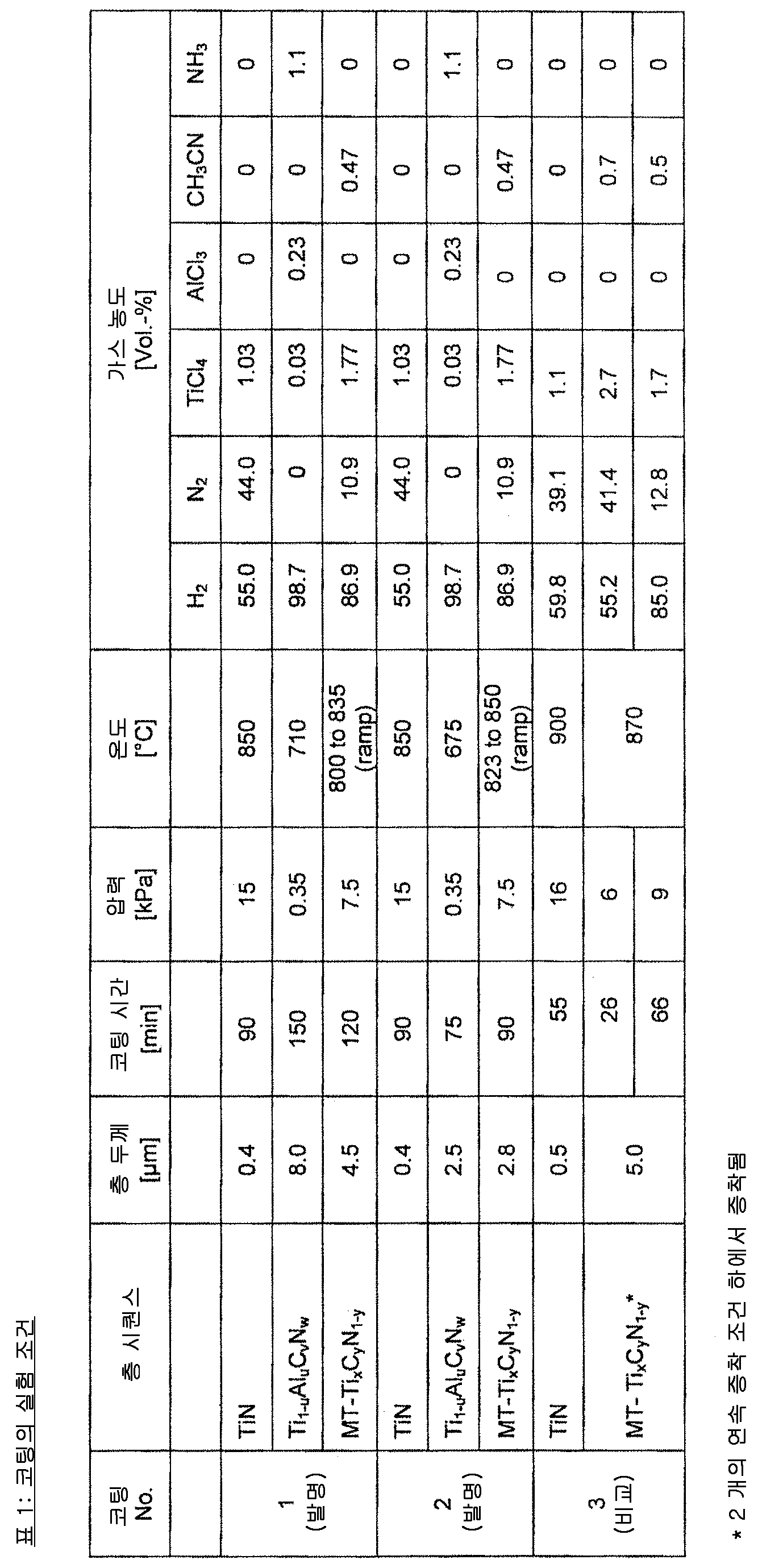
본 발명에 따른 코팅 (코팅 1 및 2) 의 증착 및 비교예 (코팅 3) 를 위한 실험 조건은 표 1 에 기재되어 있다. 본 발명에 따른 그리고 비교예의 코팅 모두는 얇은 TiN 접착층으로 시작되었다. 본 발명에 따른 제 1 Ti1 - uAluCvNw 코팅 층 및 제 2 TixCyN1 -y 코팅 층은 어떠힌 중간층 또는 조핵 단계 없이 서로의 바로 위에 증착되었다.
The experimental conditions for the deposition of the coatings (Coatings 1 and 2) according to the invention and the comparative example (Coating 3) are given in Table 1. Both the inventive and comparative coatings started with a thin TiN adhesive layer. U Al u C v N w coating layer and the 2 Ti x C y N 1 -y coating layer How hinge was deposited directly on top of one another without an intermediate layer or a nucleating step-claim 1 Ti 1 according to the present invention.
X선 X-ray 회절diffraction ( ( XRDXRD ) 측정 및 집합조직 계수) ≪ tb > <
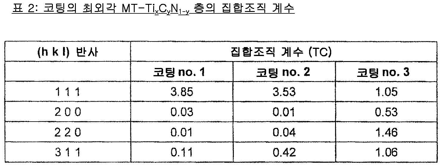
코팅의 최외각 MT-TixCyN1 -y 층을 XRD 에 의해 분석하였고, TiCN 의 (h k l) 반사 (1 1 1), (2 0 0), (2 2 0) 및 (3 1 1) 의 집합조직 계수를 본 명세서에 기재한 바와 같이 결정하였다. XRD 미가공 데이터에 박막 보정을 적용하였다. 결과를 표 2 에 나타낸다.
The outermost MT-Ti x C y N 1 -y layers of the coating were analyzed by XRD and the (hkl) reflections (1 1 1), (2 0 0), (2 2 0) and ) Were determined as described herein. Thin film compensation was applied to the raw XRD data. The results are shown in Table 2.
원소 조성의 EDS 분석EDS analysis of elemental composition
각각 TiC 및 TiN 에 대해 JCPDF 카드 번호 32-1383 및 38-1420 를 사용하여 베가드 법칙의 적용에 의해 XRD 피크 위치로부터 그리고 EDS 에 의해 코팅에서의 Ti1 - uAluCvNw 층 및 TixCyN1 -y 층의 원소 조성을 결정하였다. 결과를 표 3 에 나타낸다. 실험 오차는 ±3 at-% 로 추정된다.For TiC and TiN, respectively, from the XRD peak position by application of the Beguard rule using JCPDF card numbers 32-1383 and 38-1420 and by the EDS to the Ti 1 - u Al u C v N w layer and Ti x C y N 1 -y layer was determined. The results are shown in Table 3. The experimental error is estimated to be ± 3 at-%.

EBSDEBSD 분석 analysis
표 4 는 EBSD 측정 및 데이터 처리와 결과에 대한 세부정보를 보여준다.Table 4 shows the details of EBSD measurements and data processing and results.
CSL 경계 (Σ 입계) 의 분류를 위해, 사용된 각도 공차 Δ 는 Brandon 기준 Δ = K / Σn (K = 5, n = 0.5) 에 해당한다. 따라서, N = 2n + 1, 1 ≤ n ≤ 28 인 ΣN-타입의 CSL 경계 (=Σ3-49-타입 입계) 의 분율이 결정되었다.For classification of CSL boundaries, the angular tolerance Δ used corresponds to the Brandon criterion Δ = K / Σn (K = 5, n = 0.5). Therefore, the fraction of a CSL boundary (= Σ3-49-type grain boundary) of ΣN-type with N = 2n + 1, 1 ≦ n ≦ 28 was determined.
미스오리엔테이션 각도는 각각 세정에 사용된 입자 공차 각도와 입방정 대칭에 최대 가능한 미스오리엔테이션 각도에 의해 제한되는 5°내지 62.8°의 범위에서 평가되었다. 따라서, 입계 미스오리엔테이션의 분포는, 분포 내에서 확인된 입자들 사이의 경계만을 고려하여, 5°로부터 62.8°까지 50 피치로, 즉 1.16°의 증분으로 미스오리엔테이션 각도에 걸쳐 입계 길이의 분율을 플로팅함으로써 평가되었다. 측정된 (보정된) 미스오리엔테이션 분포의 획득된 히스토그램은 OlM 분석 소프트웨어에 의해 계산된 보정되지 않은 (집합조직 유도) 분포와 비교되었다. 미스오리엔테이션 각도의 각 피치에 대해, 보정되지 않은 수 분율로부터 보정된 미스오리엔테이션 각도 수 분율의 편차가 계산되었다. 본 발명에 따른 TixCyN1 -y 층에 대해, 편차가 모든 피치에 대해 10 보다 작은 인자만큼이라는 것이 확인되었다. 대조적으로, 종래 기술에 따른 층의 측정된 미스오리엔테이션 각도 분포는 60°에서 훨씬 더 현저한 스파이크를 보여주며, 수 분율은 보정되지 않은 수 분율보다 10 배 더 높고, 이는 높은 양의 ∑3 경계에 해당한다.The misorientation angles were evaluated in the range of 5 ° to 62.8 °, respectively, which is limited by the particle tolerance angle used for cleaning and the maximum possible misorientation angle for cubic symmetry. Thus, the distribution of grain boundary misorientation can be calculated by plotting the fraction of the grain boundary length over the misorientation angle at 50 pitches from 5 [deg.] To 62.8 [deg.], . The obtained histogram of the measured (corrected) misorientation distribution was compared to the uncorrected (aggregated tissue induced) distribution calculated by the OlM analysis software. For each pitch of the misorientation angle, the deviation of the corrected misorientation angle water fraction from the uncorrected water fraction was calculated. For the Ti x C y N 1 -y layer according to the invention, it has been confirmed that the deviation is less than 10 for all pitches. In contrast, the measured misorientation angular distribution of the layer according to the prior art shows a much more pronounced spike at 60 [deg.], And the water fraction is 10 times higher than the uncorrected water fraction, which corresponds to a high amount of [ do.

밀링milling 시험 exam
코팅 No. 1, 2 및 3 을 갖는 절삭 공구 인서트를 다음의 밀링 적용에서 검토하였다:Coating No. Cutting tool inserts with 1, 2 and 3 were examined in the following milling applications:
작업편 재료: 회색 주철 DIN GG25Work piece material: gray cast iron DIN GG25
작업: 건식 밀링Operation: Dry milling
치당 이송: fz = 0.2 ㎜Transfer per tooth: f z = 0.2 mm
절삭 깊이: ap = 3 ㎜Cutting depth: a p = 3 mm
설정 각도: κ = 45°Setting angle: κ = 45 °
절삭 속도: vc = 283 m/min
Cutting speed: v c = 283 m / min
주 절삭날에서의 최대 플랭크 마모 VBmax 의 발생 및 빗살형 균열의 수는 800 ㎜ 단차로 4800 ㎜ 의 밀링 거리에 걸쳐 관찰되었다. 표 5 에는, 밀링 거리에 걸친 VBmax 의 발생 및 4800 ㎜ 에서의 빗살형 균열의 수가 기재되어 있다.The occurrence of the maximum flank wear V Bmax at the main cutting edge and the number of comb - like cracks were observed over a milling distance of 4800 mm at 800 mm steps. Table 5 lists the generation of V Bmax over the milling distance and the number of comb-like cracks at 4800 mm.
밀링 시험에서, 본 발명에 따른 코팅은 빗살형 균열의 불발생에 의해 보여지는 것처럼 열 기계적 충격에 대한 현저하게 더 높은 저항성뿐만 아니라 플랭크 마모에 대한 훨씬 더 높은 저항성을 보여주었다.In the milling test, the coatings according to the invention showed significantly higher resistance to thermomechanical impact as well as a much higher resistance to flank wear, as seen by the non-occurrence of comb-like cracks.

Claims (9)
5 내지 25 ㎛ 의 총 코팅 두께를 가지며 화학 기상 증착 (CVD) 또는 중온 화학 기상 증착 (MT-CVD) 에 의해 증착된 적어도 2 개의 내화성 코팅 층들을 포함하는 다층 내마모성 코팅
으로 이루어지는 피복 절삭 공구로서,
상기 적어도 2 개의 내화성 코팅 층들은 서로의 위에 증착된 제 1 코팅 층 및 제 2 코팅 층을 포함하고,
상기 제 1 코팅 층은 티타늄 알루미늄 질화물 또는 탄질화물 Ti1 - uAluCvNw 로 구성되고, 0.2 ≤ u ≤ 1.0, 0 ≤ v ≤ 0.25 및 0.7 ≤ w ≤ 1.15 이고, 600 ℃ 내지 900 ℃ 의 반응 온도에서 CVD 에 의해 증착되며,
상기 제 2 코팅 층은 티타늄 탄질화물 TixCyN1 - y 로 구성되고, 0.85 ≤ x ≤ 1.1 및 0.4 ≤ y ≤ 0.85 이고, 600 ℃ 내지 900 ℃ 반응 온도에서 MT-CVD 에 의해 상기 제 1 코팅 층 위에 증착되고,
제 2 TixCyN1 -y 코팅 층은 주상 입자 모폴로지를 갖고, 상기 제 2 TixCyN1 -y 코팅 층의 전체 섬유 집합조직은 집합조직 계수 (texture coefficient) TC (1 1 1) > 2 를 특징으로 하고, 상기 TC (1 1 1) 은

로서 정의되고,
(h k l) = (hkl) 반사의 측정된 강도,
I0 (h k l) = JCPDF-카드 번호 42-1489 에 따른 표준 분말 회절 데이터의 표준 강도,
n = 계산에 사용된 반사의 수이며, 사용된 (hkl) 반사는 (1 1 1), (2 0 0), (2 2 0) 및 (3 1 1) 인, 피복 절삭 공구.A substrate of cemented carbide, cermet, ceramic, steel or cubic boron nitride, and
A multilayer abrasion-resistant coating having at least two refractory coating layers deposited by chemical vapor deposition (CVD) or by meso-chemical vapor deposition (MT-CVD)
The cutting tool comprising:
Wherein the at least two refractory coating layers comprise a first coating layer and a second coating layer deposited on top of each other,
Wherein the first coating layer is composed of titanium aluminum nitride or a carbonitride Ti 1 - u Al u C v N w , wherein 0.2 ≦ u ≦ 1.0, 0 ≦ v ≦ 0.25 and 0.7 ≦ w ≦ 1.15, Lt; RTI ID = 0.0 > CVD < / RTI >
The second coating layer of titanium carbonitride Ti x C y N 1 - is composed of y, 0.85 ≤ x ≤ 1.1 and 0.4 ≤ y ≤ 0.85, and at 600 ℃ to 900 ℃ reaction temperature by a MT-CVD of the first Deposited on the coating layer,
The second Ti x C y N 1 -y coating layer has a columnar grain morphology, and the total fiber texture of the second Ti x C y N 1 -y coating layer has a texture coefficient TC (1 1 1 ) ≫ 2, and the TC (1 1 1)
Lt; / RTI >
(hkl) = (hkl) The measured intensity of reflection,
I 0 (hkl) = standard intensity of standard powder diffraction data according to JCPDF-card number 42-1489,
where n = the number of reflections used in the calculation, and the (hkl) reflections used are (1 1 1), (2 0 0), (2 2 0) and (3 1 1).
상기 제 2 TixCyN1 -y 코팅 층은 두께 L 및 평균 입자 직경 W 을 갖고, 비 L/W < 8, 바람직하게는 L/W < 5 인, 피복 절삭 공구.The method according to claim 1,
Wherein the second Ti x C y N 1 -y coating layer has a thickness L and an average particle diameter W, and the ratio L / W < 8, preferably L / W <
상기 제 2 TixCyN1 -y 코팅 층의 입자들이 0.4 ㎛ 이상, 바람직하게는 0.7 ㎛ 이상, 더 바람직하게는 1.1 ㎛ 이상의 평균 입자 직경 W 을 갖는, 피복 절삭 공구.3. The method according to claim 1 or 2,
Wherein the particles of the second Ti x C y N 1 -y coating layer have an average particle diameter W of at least 0.4 탆, preferably at least 0.7 탆, more preferably at least 1.1 탆.
제 1 Ti1 - uAluCvNw 코팅 층은 주상 입자 모폴로지를 갖고, 상기 제 1 Ti1 -uAluCvNw 코팅 층의 전체 섬유 집합조직은 X선 회절 (XRD) 극점도 측정 또는 EBSD 측정에 의해 결정되는 {111} 결정학적 평면으로부터의 최대 회절 강도가 법선으로부터 샘플 기재 표면까지의 경사각 α = ±20°, 바람직하게는 α = ±10°, 더 바람직하게는 α = ±5°, 보다 더 바람직하게는 α = ±1°내에서 일어나는 것을 특징으로 하는, 피복 절삭 공구.4. The method according to any one of claims 1 to 3,
Claim 1 Ti 1 - u Al u C v N w coating layer has a morphology of columnar grains, wherein 1 Ti 1 full fiber texture of the Al u C v N w -u coating layer is X-ray diffraction (XRD) pole figure The maximum diffraction intensity from the {111} crystallographic plane determined by measurement or EBSD measurement is the inclination angle? = ± 20 °, preferably? = ± 10 °, more preferably? = ± 10 ° from the normal to the sample base surface Lt; RTI ID = 0.0 > = 5, < / RTI >
상기 제 2 TixCyN1 -y 코팅 층에서의 ∑3-타입 입계의 길이가 N = 2n+1 , 1 ≤ n ≤ 28 인 ∑N-타입의 입계 (=∑3-49-타입 입계) 의 합계의 총 길이의 60% 미만, 바람직하게는 40% 미만, 더 바람직하게는 30% 미만이고, 입계 특징 분포는 EBSD 에 의해 측정되는, 피복 절삭 공구.5. The method according to any one of claims 1 to 4,
Type grain boundaries (= Σ3-49-type grain boundary) having Σ 3-type grain boundary lengths in the second Ti x C y N 1 -y coating layer of N = 2n + 1 and 1 ≦ n ≦ 28 ), Preferably less than 40%, more preferably less than 30%, and the grain boundary feature distribution is measured by EBSD.
상기 제 2 TixCyN1 -y 코팅 층의 전체 섬유 집합조직은 집합조직 계수 TC (1 1 1) > 3.0, 바람직하게는 TC (1 1 1) > 3.75 를 특징으로 하는, 피복 절삭 공구.6. The method according to any one of claims 1 to 5,
Characterized in that the total fiber texture of the second Ti x C y N 1 -y coating layer is characterized by a texture coefficient TC (1 1 1)> 3.0, preferably TC (1 1 1)> 3.75. .
제 1 Ti1 - uAluCvNw 코팅 층의 결정 및 상기 제 2 TixCyN1 -y 코팅 층의 결정은 동형 결정 구조, 바람직하게는 면심 입방 (fcc) 결정 구조를 갖는, 피복 절삭 공구.7. The method according to any one of claims 1 to 6,
Claim 1 Ti 1 - u Al u C v N w and wherein the determination of the coating layer 2 Ti x C y N 1 -y crystals of the coating layer is the same type crystal structure, preferably having a face-centered cubic (fcc) crystal structure, Cloth cutting tool.
상기 다층 내마모성 코팅은 상기 기재 표면과 제 1 Ti1 - uAluCvNw 코팅 층 사이에 적어도 하나의 추가 내화성 층을 포함하고,
상기 적어도 하나의 추가 내화성 층은, Ti, Al, Zr, V 및 Hf 중의 하나 이상의 탄화물, 질화물, 탄질화물, 산탄질화물 및 붕소탄질화물 (borocarbonitrides) 또는 이들의 조합으로부터 선택되고, 화학 기상 증착 (CVD) 또는 중온 화학 기상 증착 (MT-CVD) 에 의해 증착되고, 바람직하게는 상기 적어도 하나의 추가 내화성 층은 TiN 층을 포함하거나 TiN 층으로 구성되는, 피복 절삭 공구.8. The method according to any one of claims 1 to 7,
The multi-layer wear-resistant coating the substrate surface with claim 1 Ti 1 - includes at least one additional layer of the refractory between u Al u C v N w coating layer,
Wherein the at least one further refractory layer is selected from at least one of carbides, nitrides, carbonitrides, oxycarbonitrides and borocarbonitrides of Ti, Al, Zr, V and Hf or combinations thereof, ) Or mesophilic chemical vapor deposition (MT-CVD), preferably wherein said at least one additional refractory layer comprises or consists of a TiN layer.
상기 제 1 코팅 층은 티타늄 알루미늄 질화물 또는 탄질화물 Ti1 - uAluCvNw 로 구성되고, 여기서 0.6 ≤ u ≤ 1.0, 0 ≤ v ≤ 0.1 및 0.7 ≤ w ≤ 1.15, 바람직하게는 0.8 ≤ u ≤ 1.0, 0 ≤ v ≤ 0.05 및 0.7 ≤ w ≤ 1.15 인, 피복 절삭 공구.9. The method according to any one of claims 1 to 8,
Wherein the first coating layer is comprised of titanium aluminum nitride or a carbonitride Ti 1 - u Al u C v N w wherein 0.6 ≤ u ≤ 1.0, 0 ≤ v ≤ 0.1 and 0.7 ≤ w ≤ 1.15, u? 1.0, 0? v? 0.05 and 0.7? w? 1.15.
Applications Claiming Priority (3)
| Application Number | Priority Date | Filing Date | Title |
|---|---|---|---|
| EP14186609.5A EP3000913B1 (en) | 2014-09-26 | 2014-09-26 | Coated cutting tool insert with MT-CVD TiCN on TiAI(C,N) |
| EP14186609.5 | 2014-09-26 | ||
| PCT/EP2015/070185 WO2016045937A1 (en) | 2014-09-26 | 2015-09-03 | COATED CUTTING TOOL INSERT WITH MT-CVD TiCN ON TiAl(C,N) |
Publications (2)
| Publication Number | Publication Date |
|---|---|
| KR20170056568A true KR20170056568A (en) | 2017-05-23 |
| KR102383623B1 KR102383623B1 (en) | 2022-04-05 |
Family
ID=51687806
Family Applications (1)
| Application Number | Title | Priority Date | Filing Date |
|---|---|---|---|
| KR1020177007907A KR102383623B1 (en) | 2014-09-26 | 2015-09-03 | COATED CUTTING TOOL INSERT WITH MT-CVD TiCN ON TiAl(C,N) |
Country Status (6)
| Country | Link |
|---|---|
| US (1) | US10407777B2 (en) |
| EP (1) | EP3000913B1 (en) |
| JP (1) | JP6524219B2 (en) |
| KR (1) | KR102383623B1 (en) |
| CN (1) | CN107075673B (en) |
| WO (1) | WO2016045937A1 (en) |
Families Citing this family (29)
| Publication number | Priority date | Publication date | Assignee | Title |
|---|---|---|---|---|
| JP6493800B2 (en) * | 2015-06-26 | 2019-04-03 | 三菱マテリアル株式会社 | Surface coated cutting tool with excellent wear resistance in high speed cutting |
| JP7160677B2 (en) * | 2015-07-27 | 2022-10-25 | ヴァルター アーゲー | Tool with TiAlN coating and method for manufacturing the tool |
| CN108884562A (en) * | 2016-03-31 | 2018-11-23 | 瓦尔特公开股份有限公司 | With H-ALN layers and the cutting tool of TI1-XAlXCYNZ layers of coating |
| JP6045010B1 (en) * | 2016-04-14 | 2016-12-14 | 住友電工ハードメタル株式会社 | Surface-coated cutting tool and manufacturing method thereof |
| JP6973699B2 (en) * | 2016-04-14 | 2021-12-01 | 住友電工ハードメタル株式会社 | Surface coating cutting tool and its manufacturing method |
| JP6241630B1 (en) * | 2016-07-01 | 2017-12-06 | 株式会社タンガロイ | Coated cutting tool |
| WO2018066469A1 (en) * | 2016-10-04 | 2018-04-12 | 三菱マテリアル株式会社 | Surface-coated cutting tool with hard coating layer exhibiting excellent chipping resistance |
| JP6928220B2 (en) * | 2016-10-04 | 2021-09-01 | 三菱マテリアル株式会社 | Surface coating cutting tool with excellent chipping resistance due to the hard coating layer |
| JP6210347B1 (en) * | 2016-11-04 | 2017-10-11 | 株式会社タンガロイ | Coated cutting tool |
| JP7101178B2 (en) * | 2017-01-26 | 2022-07-14 | ヴァルター アーゲー | Cutting tool with coating |
| US20200141007A1 (en) * | 2017-04-07 | 2020-05-07 | Sandvik Intellectual Property Ab | Coated cutting tool |
| JP6850998B2 (en) * | 2017-06-30 | 2021-03-31 | 三菱マテリアル株式会社 | Surface coating cutting tool with a hard coating layer that exhibits excellent wear resistance and chipping resistance |
| JP6999383B2 (en) | 2017-11-29 | 2022-01-18 | 株式会社タンガロイ | Cover cutting tool |
| JP6784928B2 (en) | 2018-09-04 | 2020-11-18 | 株式会社タンガロイ | Cover cutting tool |
| JP7285318B2 (en) * | 2018-09-28 | 2023-06-01 | コーニング インコーポレイテッド | Method for deposition of inorganic particles below austenite transformation temperature and articles made by this method |
| JP2020104255A (en) * | 2018-12-27 | 2020-07-09 | 三菱マテリアル株式会社 | Surface-coated cutting tool |
| JP6999585B2 (en) | 2019-01-18 | 2022-01-18 | 株式会社タンガロイ | Cover cutting tool |
| JP7060528B2 (en) | 2019-01-18 | 2022-04-26 | 株式会社タンガロイ | Cover cutting tool |
| JP7055761B2 (en) * | 2019-02-15 | 2022-04-18 | 株式会社タンガロイ | Cover cutting tool |
| JP6876278B2 (en) * | 2019-05-14 | 2021-05-26 | 株式会社タンガロイ | Cover cutting tool |
| JP6916472B2 (en) * | 2019-08-30 | 2021-08-11 | 株式会社タンガロイ | Cover cutting tool |
| JP7141601B2 (en) * | 2019-12-19 | 2022-09-26 | 株式会社タンガロイ | coated cutting tools |
| EP3872222B1 (en) * | 2020-02-28 | 2022-12-28 | AB Sandvik Coromant | A coated cutting tool |
| CN111438380B (en) * | 2020-05-22 | 2021-07-30 | 株洲钻石切削刀具股份有限公司 | Surface coating cutting tool and method for manufacturing same |
| WO2021245878A1 (en) * | 2020-06-04 | 2021-12-09 | 住友電工ハードメタル株式会社 | Cutting tool |
| CN112342525B (en) * | 2020-10-20 | 2023-04-28 | 厦门金鹭特种合金有限公司 | CVD (chemical vapor deposition) coating suitable for vermicular cast iron cutting processing and preparation method thereof |
| JP7124267B1 (en) * | 2021-06-30 | 2022-08-24 | 住友電工ハードメタル株式会社 | Cutting tools |
| CN115351279B (en) * | 2022-08-30 | 2023-11-21 | 株洲钻石切削刀具股份有限公司 | Coated cemented carbide cutting tool |
| CN116904961B (en) * | 2023-09-13 | 2023-12-01 | 赣州澳克泰工具技术有限公司 | Coated cutting tool with enhanced toughness and wear resistance and preparation method thereof |
Citations (1)
| Publication number | Priority date | Publication date | Assignee | Title |
|---|---|---|---|---|
| KR20140105754A (en) * | 2011-12-14 | 2014-09-02 | 산드빅 인터렉츄얼 프로퍼티 에이비 | Coated cutting tool and method of manufacturing the same |
Family Cites Families (27)
| Publication number | Priority date | Publication date | Assignee | Title |
|---|---|---|---|---|
| JPH06116731A (en) * | 1992-10-01 | 1994-04-26 | Mitsubishi Materials Corp | Surface coated cutting tool |
| JP3353449B2 (en) * | 1994-04-20 | 2002-12-03 | 住友電気工業株式会社 | Coated cutting tool |
| JPH0890310A (en) * | 1994-09-19 | 1996-04-09 | Mitsubishi Materials Corp | Surface coat cutting tool |
| EP0709483B1 (en) * | 1994-10-28 | 2002-04-10 | Sumitomo Electric Industries, Ltd. | Multilayer material |
| JPH08281502A (en) * | 1995-04-14 | 1996-10-29 | Toshiba Tungaloy Co Ltd | Crystal orientating coated tool |
| DE60037893T2 (en) | 1999-06-21 | 2008-05-21 | Sumitomo Electric Industries, Ltd. | COATED HARDMETAL |
| US6689450B2 (en) * | 2001-03-27 | 2004-02-10 | Seco Tools Ab | Enhanced Al2O3-Ti(C,N) multi-coating deposited at low temperature |
| KR100667639B1 (en) * | 2003-06-27 | 2007-01-12 | 스미토모 덴키 고교 가부시키가이샤 | Surface-coated high hardness material for tool |
| US7581906B2 (en) * | 2004-05-19 | 2009-09-01 | Tdy Industries, Inc. | Al2O3 ceramic tools with diffusion bonding enhanced layer |
| JP4466841B2 (en) | 2004-06-30 | 2010-05-26 | 三菱マテリアル株式会社 | A surface-coated cermet cutting tool that exhibits excellent chipping resistance with a hard coating layer in high-speed intermittent cutting |
| JP4518258B2 (en) | 2004-08-11 | 2010-08-04 | 三菱マテリアル株式会社 | A surface-coated cermet cutting tool that exhibits excellent chipping resistance with a hard coating layer in high-speed intermittent cutting |
| DE102005032860B4 (en) | 2005-07-04 | 2007-08-09 | Fraunhofer-Gesellschaft zur Förderung der angewandten Forschung e.V. | Hard material coated bodies and process for their production |
| DE102005049393B4 (en) | 2005-10-15 | 2019-08-08 | Kennametal Widia Produktions Gmbh & Co. Kg | Method for producing a coated substrate body, substrate body with a coating and use of the coated substrate body |
| JP4854359B2 (en) * | 2006-03-29 | 2012-01-18 | 京セラ株式会社 | Surface coated cutting tool |
| US8080312B2 (en) * | 2006-06-22 | 2011-12-20 | Kennametal Inc. | CVD coating scheme including alumina and/or titanium-containing materials and method of making the same |
| US7906230B2 (en) | 2006-09-05 | 2011-03-15 | Tungaloy Corporation | Coated cutting tool and method for producing the same |
| JP5099586B2 (en) * | 2007-08-31 | 2012-12-19 | 三菱マテリアル株式会社 | Surface-coated cutting tool with excellent fracture resistance due to hard coating layer |
| DE102007000512B3 (en) | 2007-10-16 | 2009-01-29 | Fraunhofer-Gesellschaft zur Förderung der angewandten Forschung e.V. | Hard-coated body with a multi-layer system for tools and components such as drills, millers and indexable inserts, comprises a bonding layer applied on the body, a single- or multi-phase hard layer, and a phase gradient layer |
| DE102008013966A1 (en) | 2008-03-12 | 2009-09-17 | Kennametal Inc. | Hard material coated body |
| DE102008013965A1 (en) * | 2008-03-12 | 2009-09-17 | Kennametal Inc. | Hard material coated body |
| DE102008013964A1 (en) | 2008-03-12 | 2009-09-17 | Kennametal Inc. | Hard material coated body |
| AT510963B1 (en) | 2011-03-18 | 2012-08-15 | Boehlerit Gmbh & Co Kg | COATED BODY AND METHOD FOR THE PRODUCTION THEREOF |
| JP6024981B2 (en) * | 2012-03-09 | 2016-11-16 | 三菱マテリアル株式会社 | A surface-coated cutting tool that exhibits excellent chipping resistance with a hard coating layer in high-speed intermittent cutting |
| CN103372764B (en) | 2012-04-20 | 2017-03-01 | 三菱综合材料株式会社 | Hard coating layer plays the excellent resistance to surface-coated cutting tool collapsing knife |
| JP5939508B2 (en) * | 2012-07-25 | 2016-06-22 | 三菱マテリアル株式会社 | A surface-coated cutting tool that exhibits excellent chipping resistance with a hard coating layer in high-speed intermittent cutting |
| JP6044336B2 (en) * | 2012-12-27 | 2016-12-14 | 三菱マテリアル株式会社 | Surface coated cutting tool with excellent chipping resistance due to hard coating layer |
| JP5638669B2 (en) * | 2013-07-18 | 2014-12-10 | 住友電気工業株式会社 | Surface coated cutting tool |
-
2014
- 2014-09-26 EP EP14186609.5A patent/EP3000913B1/en active Active
-
2015
- 2015-09-03 US US15/514,275 patent/US10407777B2/en active Active
- 2015-09-03 JP JP2017516455A patent/JP6524219B2/en active Active
- 2015-09-03 CN CN201580047938.1A patent/CN107075673B/en active Active
- 2015-09-03 WO PCT/EP2015/070185 patent/WO2016045937A1/en active Application Filing
- 2015-09-03 KR KR1020177007907A patent/KR102383623B1/en active IP Right Grant
Patent Citations (1)
| Publication number | Priority date | Publication date | Assignee | Title |
|---|---|---|---|---|
| KR20140105754A (en) * | 2011-12-14 | 2014-09-02 | 산드빅 인터렉츄얼 프로퍼티 에이비 | Coated cutting tool and method of manufacturing the same |
Also Published As
| Publication number | Publication date |
|---|---|
| KR102383623B1 (en) | 2022-04-05 |
| EP3000913A1 (en) | 2016-03-30 |
| CN107075673A (en) | 2017-08-18 |
| CN107075673B (en) | 2019-08-06 |
| WO2016045937A1 (en) | 2016-03-31 |
| JP6524219B2 (en) | 2019-06-05 |
| JP2017530019A (en) | 2017-10-12 |
| US10407777B2 (en) | 2019-09-10 |
| US20170275765A1 (en) | 2017-09-28 |
| EP3000913B1 (en) | 2020-07-29 |
Similar Documents
| Publication | Publication Date | Title |
|---|---|---|
| KR102383623B1 (en) | COATED CUTTING TOOL INSERT WITH MT-CVD TiCN ON TiAl(C,N) | |
| KR102372121B1 (en) | Coated cutting tool with H-ALN and TI1-XALXCYNZ layers | |
| KR102445504B1 (en) | Cvd coated cutting tool | |
| JP5715570B2 (en) | Coated tool | |
| KR102033188B1 (en) | Surface-coated cutting tool with hard coating that exhibits excellent chipping resistance and abrasion resistance | |
| US9945029B2 (en) | Coated cutting tool and method of manufacturing the same | |
| KR101965013B1 (en) | Grain boundary engineered alpha-alumina coated cutting tool | |
| KR102379497B1 (en) | Cutting tool with textured alumina layer | |
| KR102216097B1 (en) | Surface-coated cutting tool and method of manufacturing the same | |
| JP6519057B2 (en) | Method of manufacturing surface coated cutting tool | |
| JP5187571B2 (en) | Surface coated cutting tool with excellent wear resistance due to hard coating layer | |
| US9863064B2 (en) | Surface-coated cutting tool | |
| JP3818961B2 (en) | Aluminum oxide coated tools | |
| JP3781006B2 (en) | Aluminum oxide coated tools | |
| JP6535922B2 (en) | Method of manufacturing surface coated cutting tool | |
| JP2011031319A (en) | Surface coated cutting tool |
Legal Events
| Date | Code | Title | Description |
|---|---|---|---|
| E902 | Notification of reason for refusal | ||
| E701 | Decision to grant or registration of patent right | ||
| GRNT | Written decision to grant |