JP7141601B2 - coated cutting tools - Google Patents
coated cutting tools Download PDFInfo
- Publication number
- JP7141601B2 JP7141601B2 JP2019228993A JP2019228993A JP7141601B2 JP 7141601 B2 JP7141601 B2 JP 7141601B2 JP 2019228993 A JP2019228993 A JP 2019228993A JP 2019228993 A JP2019228993 A JP 2019228993A JP 7141601 B2 JP7141601 B2 JP 7141601B2
- Authority
- JP
- Japan
- Prior art keywords
- layer
- carbonitride
- coated cutting
- cutting tool
- less
- Prior art date
- Legal status (The legal status is an assumption and is not a legal conclusion. Google has not performed a legal analysis and makes no representation as to the accuracy of the status listed.)
- Active
Links
Images
Classifications
-
- B—PERFORMING OPERATIONS; TRANSPORTING
- B23—MACHINE TOOLS; METAL-WORKING NOT OTHERWISE PROVIDED FOR
- B23B—TURNING; BORING
- B23B27/00—Tools for turning or boring machines; Tools of a similar kind in general; Accessories therefor
- B23B27/14—Cutting tools of which the bits or tips or cutting inserts are of special material
-
- C—CHEMISTRY; METALLURGY
- C23—COATING METALLIC MATERIAL; COATING MATERIAL WITH METALLIC MATERIAL; CHEMICAL SURFACE TREATMENT; DIFFUSION TREATMENT OF METALLIC MATERIAL; COATING BY VACUUM EVAPORATION, BY SPUTTERING, BY ION IMPLANTATION OR BY CHEMICAL VAPOUR DEPOSITION, IN GENERAL; INHIBITING CORROSION OF METALLIC MATERIAL OR INCRUSTATION IN GENERAL
- C23C—COATING METALLIC MATERIAL; COATING MATERIAL WITH METALLIC MATERIAL; SURFACE TREATMENT OF METALLIC MATERIAL BY DIFFUSION INTO THE SURFACE, BY CHEMICAL CONVERSION OR SUBSTITUTION; COATING BY VACUUM EVAPORATION, BY SPUTTERING, BY ION IMPLANTATION OR BY CHEMICAL VAPOUR DEPOSITION, IN GENERAL
- C23C30/00—Coating with metallic material characterised only by the composition of the metallic material, i.e. not characterised by the coating process
- C23C30/005—Coating with metallic material characterised only by the composition of the metallic material, i.e. not characterised by the coating process on hard metal substrates
-
- C—CHEMISTRY; METALLURGY
- C23—COATING METALLIC MATERIAL; COATING MATERIAL WITH METALLIC MATERIAL; CHEMICAL SURFACE TREATMENT; DIFFUSION TREATMENT OF METALLIC MATERIAL; COATING BY VACUUM EVAPORATION, BY SPUTTERING, BY ION IMPLANTATION OR BY CHEMICAL VAPOUR DEPOSITION, IN GENERAL; INHIBITING CORROSION OF METALLIC MATERIAL OR INCRUSTATION IN GENERAL
- C23C—COATING METALLIC MATERIAL; COATING MATERIAL WITH METALLIC MATERIAL; SURFACE TREATMENT OF METALLIC MATERIAL BY DIFFUSION INTO THE SURFACE, BY CHEMICAL CONVERSION OR SUBSTITUTION; COATING BY VACUUM EVAPORATION, BY SPUTTERING, BY ION IMPLANTATION OR BY CHEMICAL VAPOUR DEPOSITION, IN GENERAL
- C23C16/00—Chemical coating by decomposition of gaseous compounds, without leaving reaction products of surface material in the coating, i.e. chemical vapour deposition [CVD] processes
- C23C16/22—Chemical coating by decomposition of gaseous compounds, without leaving reaction products of surface material in the coating, i.e. chemical vapour deposition [CVD] processes characterised by the deposition of inorganic material, other than metallic material
- C23C16/30—Deposition of compounds, mixtures or solid solutions, e.g. borides, carbides, nitrides
- C23C16/301—AIII BV compounds, where A is Al, Ga, In or Tl and B is N, P, As, Sb or Bi
- C23C16/303—Nitrides
-
- C—CHEMISTRY; METALLURGY
- C23—COATING METALLIC MATERIAL; COATING MATERIAL WITH METALLIC MATERIAL; CHEMICAL SURFACE TREATMENT; DIFFUSION TREATMENT OF METALLIC MATERIAL; COATING BY VACUUM EVAPORATION, BY SPUTTERING, BY ION IMPLANTATION OR BY CHEMICAL VAPOUR DEPOSITION, IN GENERAL; INHIBITING CORROSION OF METALLIC MATERIAL OR INCRUSTATION IN GENERAL
- C23C—COATING METALLIC MATERIAL; COATING MATERIAL WITH METALLIC MATERIAL; SURFACE TREATMENT OF METALLIC MATERIAL BY DIFFUSION INTO THE SURFACE, BY CHEMICAL CONVERSION OR SUBSTITUTION; COATING BY VACUUM EVAPORATION, BY SPUTTERING, BY ION IMPLANTATION OR BY CHEMICAL VAPOUR DEPOSITION, IN GENERAL
- C23C16/00—Chemical coating by decomposition of gaseous compounds, without leaving reaction products of surface material in the coating, i.e. chemical vapour deposition [CVD] processes
- C23C16/22—Chemical coating by decomposition of gaseous compounds, without leaving reaction products of surface material in the coating, i.e. chemical vapour deposition [CVD] processes characterised by the deposition of inorganic material, other than metallic material
- C23C16/30—Deposition of compounds, mixtures or solid solutions, e.g. borides, carbides, nitrides
- C23C16/32—Carbides
-
- C—CHEMISTRY; METALLURGY
- C23—COATING METALLIC MATERIAL; COATING MATERIAL WITH METALLIC MATERIAL; CHEMICAL SURFACE TREATMENT; DIFFUSION TREATMENT OF METALLIC MATERIAL; COATING BY VACUUM EVAPORATION, BY SPUTTERING, BY ION IMPLANTATION OR BY CHEMICAL VAPOUR DEPOSITION, IN GENERAL; INHIBITING CORROSION OF METALLIC MATERIAL OR INCRUSTATION IN GENERAL
- C23C—COATING METALLIC MATERIAL; COATING MATERIAL WITH METALLIC MATERIAL; SURFACE TREATMENT OF METALLIC MATERIAL BY DIFFUSION INTO THE SURFACE, BY CHEMICAL CONVERSION OR SUBSTITUTION; COATING BY VACUUM EVAPORATION, BY SPUTTERING, BY ION IMPLANTATION OR BY CHEMICAL VAPOUR DEPOSITION, IN GENERAL
- C23C16/00—Chemical coating by decomposition of gaseous compounds, without leaving reaction products of surface material in the coating, i.e. chemical vapour deposition [CVD] processes
- C23C16/22—Chemical coating by decomposition of gaseous compounds, without leaving reaction products of surface material in the coating, i.e. chemical vapour deposition [CVD] processes characterised by the deposition of inorganic material, other than metallic material
- C23C16/30—Deposition of compounds, mixtures or solid solutions, e.g. borides, carbides, nitrides
- C23C16/34—Nitrides
-
- C—CHEMISTRY; METALLURGY
- C23—COATING METALLIC MATERIAL; COATING MATERIAL WITH METALLIC MATERIAL; CHEMICAL SURFACE TREATMENT; DIFFUSION TREATMENT OF METALLIC MATERIAL; COATING BY VACUUM EVAPORATION, BY SPUTTERING, BY ION IMPLANTATION OR BY CHEMICAL VAPOUR DEPOSITION, IN GENERAL; INHIBITING CORROSION OF METALLIC MATERIAL OR INCRUSTATION IN GENERAL
- C23C—COATING METALLIC MATERIAL; COATING MATERIAL WITH METALLIC MATERIAL; SURFACE TREATMENT OF METALLIC MATERIAL BY DIFFUSION INTO THE SURFACE, BY CHEMICAL CONVERSION OR SUBSTITUTION; COATING BY VACUUM EVAPORATION, BY SPUTTERING, BY ION IMPLANTATION OR BY CHEMICAL VAPOUR DEPOSITION, IN GENERAL
- C23C16/00—Chemical coating by decomposition of gaseous compounds, without leaving reaction products of surface material in the coating, i.e. chemical vapour deposition [CVD] processes
- C23C16/22—Chemical coating by decomposition of gaseous compounds, without leaving reaction products of surface material in the coating, i.e. chemical vapour deposition [CVD] processes characterised by the deposition of inorganic material, other than metallic material
- C23C16/30—Deposition of compounds, mixtures or solid solutions, e.g. borides, carbides, nitrides
- C23C16/36—Carbonitrides
-
- C—CHEMISTRY; METALLURGY
- C23—COATING METALLIC MATERIAL; COATING MATERIAL WITH METALLIC MATERIAL; CHEMICAL SURFACE TREATMENT; DIFFUSION TREATMENT OF METALLIC MATERIAL; COATING BY VACUUM EVAPORATION, BY SPUTTERING, BY ION IMPLANTATION OR BY CHEMICAL VAPOUR DEPOSITION, IN GENERAL; INHIBITING CORROSION OF METALLIC MATERIAL OR INCRUSTATION IN GENERAL
- C23C—COATING METALLIC MATERIAL; COATING MATERIAL WITH METALLIC MATERIAL; SURFACE TREATMENT OF METALLIC MATERIAL BY DIFFUSION INTO THE SURFACE, BY CHEMICAL CONVERSION OR SUBSTITUTION; COATING BY VACUUM EVAPORATION, BY SPUTTERING, BY ION IMPLANTATION OR BY CHEMICAL VAPOUR DEPOSITION, IN GENERAL
- C23C16/00—Chemical coating by decomposition of gaseous compounds, without leaving reaction products of surface material in the coating, i.e. chemical vapour deposition [CVD] processes
- C23C16/22—Chemical coating by decomposition of gaseous compounds, without leaving reaction products of surface material in the coating, i.e. chemical vapour deposition [CVD] processes characterised by the deposition of inorganic material, other than metallic material
- C23C16/30—Deposition of compounds, mixtures or solid solutions, e.g. borides, carbides, nitrides
- C23C16/40—Oxides
- C23C16/403—Oxides of aluminium, magnesium or beryllium
-
- C—CHEMISTRY; METALLURGY
- C23—COATING METALLIC MATERIAL; COATING MATERIAL WITH METALLIC MATERIAL; CHEMICAL SURFACE TREATMENT; DIFFUSION TREATMENT OF METALLIC MATERIAL; COATING BY VACUUM EVAPORATION, BY SPUTTERING, BY ION IMPLANTATION OR BY CHEMICAL VAPOUR DEPOSITION, IN GENERAL; INHIBITING CORROSION OF METALLIC MATERIAL OR INCRUSTATION IN GENERAL
- C23C—COATING METALLIC MATERIAL; COATING MATERIAL WITH METALLIC MATERIAL; SURFACE TREATMENT OF METALLIC MATERIAL BY DIFFUSION INTO THE SURFACE, BY CHEMICAL CONVERSION OR SUBSTITUTION; COATING BY VACUUM EVAPORATION, BY SPUTTERING, BY ION IMPLANTATION OR BY CHEMICAL VAPOUR DEPOSITION, IN GENERAL
- C23C28/00—Coating for obtaining at least two superposed coatings either by methods not provided for in a single one of groups C23C2/00 - C23C26/00 or by combinations of methods provided for in subclasses C23C and C25C or C25D
- C23C28/04—Coating for obtaining at least two superposed coatings either by methods not provided for in a single one of groups C23C2/00 - C23C26/00 or by combinations of methods provided for in subclasses C23C and C25C or C25D only coatings of inorganic non-metallic material
- C23C28/044—Coating for obtaining at least two superposed coatings either by methods not provided for in a single one of groups C23C2/00 - C23C26/00 or by combinations of methods provided for in subclasses C23C and C25C or C25D only coatings of inorganic non-metallic material coatings specially adapted for cutting tools or wear applications
-
- B—PERFORMING OPERATIONS; TRANSPORTING
- B23—MACHINE TOOLS; METAL-WORKING NOT OTHERWISE PROVIDED FOR
- B23B—TURNING; BORING
- B23B2228/00—Properties of materials of tools or workpieces, materials of tools or workpieces applied in a specific manner
- B23B2228/04—Properties of materials of tools or workpieces, materials of tools or workpieces applied in a specific manner applied by chemical vapour deposition [CVD]
-
- B—PERFORMING OPERATIONS; TRANSPORTING
- B23—MACHINE TOOLS; METAL-WORKING NOT OTHERWISE PROVIDED FOR
- B23B—TURNING; BORING
- B23B2228/00—Properties of materials of tools or workpieces, materials of tools or workpieces applied in a specific manner
- B23B2228/10—Coatings
- B23B2228/105—Coatings with specified thickness
-
- B—PERFORMING OPERATIONS; TRANSPORTING
- B23—MACHINE TOOLS; METAL-WORKING NOT OTHERWISE PROVIDED FOR
- B23B—TURNING; BORING
- B23B2228/00—Properties of materials of tools or workpieces, materials of tools or workpieces applied in a specific manner
- B23B2228/36—Multi-layered
Description
本発明は、被覆切削工具に関する。 The present invention relates to coated cutting tools.
従来、超硬合金からなる基材の表面に化学蒸着法により3~20μmの総膜厚で被覆層を蒸着形成してなる被覆切削工具が、鋼や鋳鉄等の切削加工に用いられていることは、よく知られている。上記の被覆層としては、例えば、Tiの炭化物、窒化物、炭窒化物、炭酸化物及び炭窒酸化物並びに酸化アルミニウムからなる群より選ばれる1種の単層又は2種以上の複層からなる被覆層が知られている。 Conventionally, a coated cutting tool formed by depositing a coating layer with a total thickness of 3 to 20 μm on the surface of a base material made of cemented carbide by chemical vapor deposition is used for cutting steel, cast iron, etc. is well known. As the coating layer, for example, one kind of single layer or two or more kinds of multiple layers selected from the group consisting of Ti carbides, nitrides, carbonitrides, carbonates, carbonitrides, and aluminum oxide Coating layers are known.
特許文献1には、炭化タングステン基超硬合金又は炭窒化チタン基サーメットからなるサーメット基体の表面に、Tiの炭化物、窒化物、炭窒化物及び炭窒酸化物、並びに酸化アルミニウムのうちの2種以上の複層からなる硬質被覆層を化学蒸着法にて形成してなる表面被覆サーメット製切削工具において、硬質被覆層のうちの基体表面に接する第1層を除く構成層のうちの少なくとも1層を炭窒化チタンで構成し、かつこの炭窒化チタン層のうちの少なくとも1層を、X線回折における(422)面に最高ピーク強度を示す炭窒化チタンで構成したことを特徴とする硬質被覆層の耐摩耗性が向上した表面被覆サーメット製切削工具が記載されている。
In
特許文献2には、基材と基材上に形成された被膜とを含み、被膜は、少なくとも一層のTiCN層を含み、TiCN層は、柱状晶領域を有し、柱状晶領域は、TiCxNy(ただし0.65≦x/(x+y)≦0.90)という組成を有し、(422)面の面間隔が0.8765~0.8780Åであり、かつ配向性指数TC(hkl)においてTC(422)が最大となる、表面被覆切削工具が記載されている。
特許文献3には、基材と基材上に形成された被膜とを含み、被膜は、少なくとも一層のTiCN層を含み、TiCN層は、柱状晶領域を有し、柱状晶領域は、TiCxNy(ただし0.65≦x/(x+y)≦0.90)という組成を有し、(422)面の面間隔が0.8765~0.8790Åであり、かつ配向性指数TC(hkl)においてTC(220)が最大となる、表面被覆切削工具が記載されている。
近年の切削加工では、高速化、高送り化及び深切り込み化がより顕著となり、また、被削材の高強度化により、従来よりも工具の耐摩耗性及び耐欠損性を向上させることが求められている。特に、近年、鋳鉄は薄肉化を達成するために強度が向上し、切削加工においては、鋳鉄の高速切削等、被覆切削工具に負荷が作用するような切削加工が増えている。かかる過酷な切削条件下において、特許文献1~3に記載のような従来の被覆切削工具では、摩耗の進行が早いため工具寿命を長くできない場合があったり、靭性が不十分なためチッピング及び欠損が生じる場合があったりする。
In recent years, cutting speeds, feeds, and depths of cut have become more pronounced, and due to the increased strength of the work material, it is required to improve the wear resistance and chipping resistance of tools more than before. It is In particular, in recent years, cast iron has been improved in strength in order to achieve thinning, and in cutting, such as high-speed cutting of cast iron, cutting that applies a load to a coated cutting tool is increasing. Under such severe cutting conditions, conventional coated cutting tools such as those described in
このような背景の下、特許文献1に記載の表面被覆サーメット製切削工具は、被覆層における炭素の含有量が低いことから、硬さが低く、耐摩耗性が不十分となる場合がある。また、特許文献2に記載の表面被覆切削工具は、被覆層におけるTiの炭窒化物層を形成する温度が低いことから密着性が不十分な場合があったり、耐摩耗性が不十分な場合があったりする。特許文献3に記載の表面被覆切削工具は、被覆層におけるTiの炭窒化物層の耐摩耗性には一定の効果が認められるものの、靭性が不十分である場合があり、この結果、耐チッピング性及び耐欠損性が不十分な場合がある。
Under such circumstances, the surface-coated cermet cutting tool described in
本発明は上記事情に鑑みてなされたものであり、優れた耐摩耗性及び耐欠損性を有することによって工具寿命を延長することができる被覆切削工具を提供することを目的とする。 The present invention has been made in view of the above circumstances, and an object thereof is to provide a coated cutting tool that can extend the tool life by having excellent wear resistance and chipping resistance.
本発明者は、上述の観点から、被覆切削工具の工具寿命の延長について研究を重ねたところ、被覆層が少なくとも1層のTiの炭窒化物層を含み、Tiの炭窒化物層における(331)面の組織係数を所定の範囲とすることを含む以下の構成にすると、Tiの炭窒化物層における炭素の原子比が0.65を超え0.90以下の範囲であっても、耐摩耗性及び耐欠損性のバランスに優れ、その結果、工具寿命を延長することが可能になるという知見を得て、本発明を完成するに至った。 From the above-mentioned viewpoint, the present inventor has conducted research on extending the tool life of coated cutting tools, and found that the coating layer includes at least one Ti carbonitride layer, and the Ti carbonitride layer (331 ) with the following configuration including setting the texture coefficient of the surface to a predetermined range, even if the atomic ratio of carbon in the Ti carbonitride layer is in the range of more than 0.65 to 0.90 or less, wear resistance The present inventors have completed the present invention based on the knowledge that the tool life can be extended as a result of the excellent balance between durability and chipping resistance.
すなわち、本発明は下記のとおりである。
[1]
基材と、該基材の表面上に形成された被覆層とを備える被覆切削工具であって、
前記被覆層が、下部層と、該下部層の表面上に形成された上部層とを含み、
前記下部層が、Tiの炭化物層、Tiの窒化物層、Tiの炭窒化物層、Tiの炭酸化物層及びTiの炭窒酸化物層からなる群より選択される1種以上の層からなるTi化合物層であり、
前記下部層の平均厚さが、3.0μm以上15.0μm以下であり、
前記上部層が、α型酸化アルミニウム層からなり、
前記上部層の平均厚さが、3.0μm以上15.0μm以下であり、
前記Ti化合物層が、少なくとも1層のTiの炭窒化物層を含み、
前記Tiの炭窒化物層が下記式(i)で表される組成からなり、
Ti(CxN1-x) (i)
(式中、xは、前記Tiの炭窒化物層において、C元素とN元素との合計に対するC元素の原子比を表し、0.65<x≦0.90を満足する。)
前記Tiの炭窒化物層において、下記式(1)で表される(331)面の組織係数TC(331)が、1.5以上4.0以下である、被覆切削工具。

[2]
前記Tiの炭窒化物層において、前記組織係数TC(331)が、2.0以上4.0以下である、[1]に記載の被覆切削工具。
[3]
前記Tiの炭窒化物層を構成する粒子の平均粒径が、0.3μm以上2.0μm以下である、[1]又は[2]に記載の被覆切削工具。
[4]
前記被覆層が、前記上部層の表面に形成された外層を含み、
前記外層が、Tiの窒化物層及び/又はTiの炭窒化物層からなり、
前記外層の平均厚さが、0.1μm以上5.0μm以下である、[1]~[3]のいずれかに記載の被覆切削工具。
[5]
前記被覆層全体の平均厚さが、7.5μm以上25.0μm以下である、[1]~[4]のいずれかに記載の被覆切削工具。
[6]
前記基材が、超硬合金、サーメット、セラミックス及び立方晶窒化硼素焼結体のいずれかである、[1]~[5]のいずれかに記載の被覆切削工具。
That is, the present invention is as follows.
[1]
A coated cutting tool comprising a substrate and a coating layer formed on the surface of the substrate,
the coating layer comprises a lower layer and an upper layer formed on the surface of the lower layer;
The lower layer comprises one or more layers selected from the group consisting of a Ti carbide layer, a Ti nitride layer, a Ti carbonitride layer, a Ti carbonate layer and a Ti carbonitride layer. is a Ti compound layer,
The average thickness of the lower layer is 3.0 μm or more and 15.0 μm or less,
the upper layer is composed of an α-type aluminum oxide layer,
The average thickness of the upper layer is 3.0 μm or more and 15.0 μm or less,
The Ti compound layer includes at least one Ti carbonitride layer,
The Ti carbonitride layer has a composition represented by the following formula (i),
Ti(CxN1 -x ) (i)
(In the formula, x represents the atomic ratio of the C element to the sum of the C element and the N element in the Ti carbonitride layer, and satisfies 0.65<x≦0.90.)
A coated cutting tool, wherein the Ti carbonitride layer has a (331) surface texture coefficient TC(331) represented by the following formula (1) of 1.5 or more and 4.0 or less.
[2]
The coated cutting tool according to [1], wherein the Ti carbonitride layer has a texture coefficient TC(331) of 2.0 or more and 4.0 or less.
[3]
The coated cutting tool according to [1] or [2], wherein the particles constituting the Ti carbonitride layer have an average particle size of 0.3 μm or more and 2.0 μm or less.
[4]
The coating layer comprises an outer layer formed on the surface of the upper layer,
The outer layer consists of a Ti nitride layer and/or a Ti carbonitride layer,
The coated cutting tool according to any one of [1] to [3], wherein the outer layer has an average thickness of 0.1 μm or more and 5.0 μm or less.
[5]
The coated cutting tool according to any one of [1] to [4], wherein the coating layer has an average thickness of 7.5 μm or more and 25.0 μm or less.
[6]
The coated cutting tool according to any one of [1] to [5], wherein the substrate is any one of cemented carbide, cermet, ceramics and cubic boron nitride sintered body.
本発明によると、優れた耐摩耗性及び耐欠損性を有することによって工具寿命を延長することができる被覆切削工具を提供することができる。 ADVANTAGE OF THE INVENTION According to this invention, the coated cutting tool which can extend tool life by having excellent wear resistance and chipping resistance can be provided.
以下、必要に応じて図面を参照しつつ、本発明を実施するための形態(以下、単に「本実施形態」という。)について詳細に説明するが、本発明は下記本実施形態に限定されるものではない。本発明は、その要旨を逸脱しない範囲で様々な変形が可能である。なお、図面中、上下左右等の位置関係は、特に断らない限り、図面に示す位置関係に基づくものとする。更に、図面の寸法比率は図示の比率に限られるものではない。 Hereinafter, a mode for carrying out the present invention (hereinafter simply referred to as "this embodiment") will be described in detail with reference to the drawings as necessary, but the present invention is limited to the following embodiment. not a thing Various modifications are possible for the present invention without departing from the gist thereof. Unless otherwise specified, the positional relationships in the drawings, such as up, down, left, and right, are based on the positional relationships shown in the drawings. Furthermore, the dimensional ratios of the drawings are not limited to the illustrated ratios.
本実施形態の被覆切削工具は、基材と、該基材の表面上に形成された被覆層とを備える被覆切削工具であって、被覆層が、下部層と、該下部層の表面上に形成された上部層とを含み、下部層が、Tiの炭化物層、Tiの窒化物層、Tiの炭窒化物層、Tiの炭酸化物層及びTiの炭窒酸化物層からなる群より選択される1種以上の層からなるTi化合物層であり、下部層の平均厚さが、3.0μm以上15.0μm以下であり、上部層が、α型酸化アルミニウム層からなり、上部層の平均厚さが、3.0μm以上15.0μm以下であり、Ti化合物層が、少なくとも1層のTiの炭窒化物層を含み、Tiの炭窒化物層が下記式(i)で表される組成からなり、Tiの炭窒化物層において、下記式(1)で表される(331)面の組織係数TC(331)が、1.5以上4.0以下である。
Ti(CxN1-x) (i)
(式中、xは、Tiの炭窒化物層において、C元素とN元素との合計に対するC元素の原子比を表し、0.65<x≦0.90を満足する。)

Ti(CxN1 -x ) (i)
(In the formula, x represents the atomic ratio of the C element to the sum of the C element and the N element in the Ti carbonitride layer, and satisfies 0.65<x≦0.90.)
本実施形態の被覆切削工具は、上記の構成を備えることにより、高強度の被削材を加工する切削条件、負荷が作用するような切削加工条件下でも耐摩耗性及び耐欠損性のバランスに優れるので、工具寿命を延長することができる。本実施形態の被覆切削工具の耐摩耗性及び耐欠損性が向上する要因は、以下のように考えられる。ただし、要因は以下のものに限定されない。まず、本実施形態の被覆切削工具は、下部層に含まれるTiの炭窒化物層がTi(CxN1-x)で表される組成からなり、該組成Ti(CxN1-x)において、xが0.65を超えると、硬さが向上することにより、耐摩耗性が向上し、xが0.90以下であると、硬さが高くなることによる靭性の低下を抑制し、耐欠損性が向上する。また、本実施形態の被覆切削工具は、下部層に含まれるTiの炭窒化物層において、上記式(1)で表される(331)面の組織係数TC(331)が、1.5以上であると、組成Ti(CxN1-x)中のxを特定の大きい範囲としても、Tiの炭窒化物層を構成する粒子の粒径を大きくすることができ、この結果、靭性が向上する。これにより、本実施形態の被覆切削工具は、耐摩耗性及び耐欠損性が向上する。一方、本実施形態の被覆切削工具は、下部層に含まれるTiの炭窒化物層において、上記式(1)で表される(331)面の組織係数TC(331)が、4.0以下であると、容易に製造することができる。また、本実施形態の被覆切削工具は、上部層が、α型酸化アルミニウム層からなることにより、下部層のTi化合物層の酸化による反応摩耗を抑制することができ、この結果、耐摩耗性が向上する。これらの効果が相俟って、本実施形態の被覆切削工具は、耐摩耗性及び耐欠損性のバランスに優れ、工具寿命を延長することができる。 The coated cutting tool of the present embodiment has the above configuration, so that it has a good balance of wear resistance and chipping resistance even under cutting conditions such as cutting conditions for machining high-strength work materials and cutting conditions where loads are applied. It is excellent and can extend the tool life. The factors that improve the wear resistance and chipping resistance of the coated cutting tool of the present embodiment are considered as follows. However, the factors are not limited to the following. First, in the coated cutting tool of the present embodiment, the Ti carbonitride layer contained in the lower layer has a composition represented by Ti(C x N 1-x ), and the composition Ti (C x N 1-x ), when x exceeds 0.65, wear resistance improves due to an increase in hardness, and when x is 0.90 or less, a decrease in toughness due to an increase in hardness is suppressed. , chipping resistance is improved. In addition, in the coated cutting tool of the present embodiment, the Ti carbonitride layer contained in the lower layer has a (331) plane texture coefficient TC (331) represented by the above formula (1) of 1.5 or more. Then, even if x in the composition Ti (C x N 1-x ) is set to a specific large range, the grain size of the particles constituting the Ti carbonitride layer can be increased, and as a result, the toughness is improved. improves. Thereby, the coated cutting tool of the present embodiment has improved wear resistance and chipping resistance. On the other hand, in the coated cutting tool of the present embodiment, in the Ti carbonitride layer contained in the lower layer, the texture coefficient TC (331) of the (331) plane represented by the above formula (1) is 4.0 or less. , it can be easily manufactured. In addition, in the coated cutting tool of the present embodiment, since the upper layer is composed of the α-type aluminum oxide layer, it is possible to suppress reaction wear due to oxidation of the Ti compound layer of the lower layer, and as a result, wear resistance is improved. improves. Combined with these effects, the coated cutting tool of the present embodiment has an excellent balance between wear resistance and chipping resistance, and can extend the tool life.
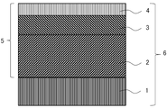
図1は、本実施形態の被覆切削工具の一例を示す断面模式図である。被覆切削工具6は、基材1と、基材1の表面に被覆層5が形成されている。被覆層5では、基材1側から、下部層2、上部層3、及び外層4がこの順序で上方向に積層されている。
FIG. 1 is a schematic cross-sectional view showing an example of the coated cutting tool of this embodiment. The
本実施形態の被覆切削工具は、基材とその基材の表面上に形成された被覆層とを備える。被覆切削工具の種類として、具体的には、フライス加工用若しくは旋削加工用刃先交換型切削インサート、ドリル及びエンドミルを挙げることができる。 The coated cutting tool of this embodiment comprises a substrate and a coating layer formed on the surface of the substrate. Examples of the types of coated cutting tools include indexable cutting inserts for milling or turning, drills and end mills.
本実施形態における基材は、被覆切削工具の基材として用いられ得るものであれば、特に限定されない。そのような基材として、例えば、超硬合金、サーメット、セラミックス、立方晶窒化硼素焼結体、ダイヤモンド焼結体及び高速度鋼を挙げることができる。それらの中でも、基材が、超硬合金、サーメット、セラミックス及び立方晶窒化硼素焼結体のいずれかであると、耐摩耗性及び耐欠損性に更に優れるので好ましく、同様の観点から、基材が超硬合金であるとより好ましい。 The base material in the present embodiment is not particularly limited as long as it can be used as a base material for coated cutting tools. Examples of such substrates include cemented carbides, cermets, ceramics, cubic boron nitride sintered bodies, diamond sintered bodies, and high speed steels. Among them, it is preferable that the base material is any one of cemented carbide, cermet, ceramics, and cubic boron nitride sintered body because it is more excellent in wear resistance and chipping resistance. is more preferably a cemented carbide.
なお、基材は、その表面が改質されたものであってもよい。例えば、基材が超硬合金からなるものである場合、その表面に脱β層が形成されてもよい。また、基材がサーメットからなるものである場合、その表面に硬化層が形成されてもよい。これらのように基材の表面が改質されていても、本発明の作用効果は奏される。 The base material may have a modified surface. For example, if the base material is made of a cemented carbide, a β-free layer may be formed on its surface. Moreover, when the base material is made of cermet, a hardened layer may be formed on the surface thereof. Even if the surface of the substrate is modified as described above, the effects of the present invention can be obtained.
本実施形態における被覆層全体の平均厚さは、7.5μm以上25.0μm以下であると好ましい。平均厚さが7.5μm以上であると、耐摩耗性が向上し、25.0μm以下であると、被覆層の基材との密着性及び耐欠損性が向上する。同様の観点から、被覆層の平均厚さは、8.0μm以上24.0μm以下であるとより好ましく、10.0μm以上23.0μm以下であることが更に好ましい。なお、本実施形態の被覆切削工具における各層及び被覆層全体の平均厚さは、各層又は被覆層全体における3箇所以上の断面から、各層の厚さ又は被覆層全体の厚さを測定して、その相加平均値を計算することで求めることができる。 The average thickness of the entire coating layer in the present embodiment is preferably 7.5 μm or more and 25.0 μm or less. When the average thickness is 7.5 μm or more, the wear resistance is improved, and when it is 25.0 μm or less, the adhesion of the coating layer to the substrate and the chipping resistance are improved. From the same point of view, the average thickness of the coating layer is more preferably 8.0 μm or more and 24.0 μm or less, and still more preferably 10.0 μm or more and 23.0 μm or less. The average thickness of each layer and the entire coating layer in the coated cutting tool of the present embodiment is obtained by measuring the thickness of each layer or the thickness of the entire coating layer from three or more sections of each layer or the entire coating layer, It can be obtained by calculating the arithmetic mean value.
[下部層]
本実施形態の下部層は、Tiの炭化物層(以下、「TiC層」とも表記する。)、Tiの窒化物層(以下、「TiN層」とも表記する。)、Tiの炭窒化物層(以下、「TiCN層」とも表記する。)、Tiの炭酸化物層(以下、「TiCO層」とも表記する。)及びTiの炭窒酸化物層(以下、「TiCNO層」とも表記する。)からなる群より選択される1種以上の層からなるTi化合物層である。被覆切削工具が、基材とα型酸化アルミニウム(以下、「α型Al2O3」とも表記する。)を含有する上部層との間に、下部層を備えると、耐摩耗性及び密着性が向上する。
[Lower layer]
The lower layer of the present embodiment includes a Ti carbide layer (hereinafter also referred to as "TiC layer"), a Ti nitride layer (hereinafter also referred to as "TiN layer"), a Ti carbonitride layer ( Hereinafter, also referred to as a “TiCN layer”), a Ti carbonate layer (hereinafter also referred to as a “TiCO layer”), and a Ti carbonitride layer (hereinafter also referred to as a “TiCNO layer”). It is a Ti compound layer consisting of one or more layers selected from the group consisting of. When the coated cutting tool is provided with a lower layer between the base material and the upper layer containing α-type aluminum oxide (hereinafter also referred to as "α-type Al 2 O 3 "), wear resistance and adhesion improves.
下部層は、1層で構成されていてもよく、複層(例えば、2層又は3層)で構成されてもよいが、複層で構成されていることが好ましく、2層又は3層で構成されていることがより好ましく、3層で構成されていることが更に好ましい。下部層が3層で構成されている場合には、基材の表面上に、TiC層又はTiN層を第1層として有し、第1層の表面上に、TiCN層を第2層として有し、第2層の表面上に、TiCNO層又はTiCO層を第3層として有してもよい。それらの中では、下部層が基材の表面上にTiN層を第1層として有し、第1層の表面上に、TiCN層を第2層として有し、第2層の表面上に、TiCNO層を第3層として有してもよい。 The lower layer may be composed of one layer or may be composed of multiple layers (e.g., two or three layers), but is preferably composed of multiple layers, and may be composed of two or three layers. It is more preferable that it is composed of three layers. When the lower layer is composed of three layers, it has a TiC layer or a TiN layer as the first layer on the surface of the substrate, and a TiCN layer as the second layer on the surface of the first layer. However, a TiCNO layer or a TiCO layer may be provided as a third layer on the surface of the second layer. Among them, the bottom layer has a TiN layer as a first layer on the surface of the substrate, a TiCN layer as a second layer on the surface of the first layer, and a TiCN layer on the surface of the second layer: A TiCNO layer may be included as the third layer.
本実施形態の下部層の平均厚さは、3.0μm以上15.0μm以下である。平均厚さが3.0μm以上であることにより、耐摩耗性が向上する。一方、下部層の平均厚さが15.0μm以下であることにより、被覆層の剥離が抑制されることに主に起因して耐欠損性が向上する。同様の観点から、下部層の平均厚さは、4.0μm以上14.5μm以下であることがより好ましく、5.0μm以上14.0μm以下であることが更に好ましい。 The average thickness of the lower layer of this embodiment is 3.0 μm or more and 15.0 μm or less. Abrasion resistance improves when the average thickness is 3.0 μm or more. On the other hand, when the average thickness of the lower layer is 15.0 μm or less, chipping resistance is improved mainly due to suppression of peeling of the coating layer. From the same point of view, the average thickness of the lower layer is more preferably 4.0 μm or more and 14.5 μm or less, and even more preferably 5.0 μm or more and 14.0 μm or less.
第1層(TiC層又はTiN層)の平均厚さは、耐摩耗性及び耐欠損性を一層向上する観点から、0.05μm以上1.0μm以下であることが好ましい。同様の観点から、第1層(TiC層又はTiN層)の平均厚さは、0.10μm以上0.50μm以下であることがより好ましく、0.15μm以上0.30μm以下であることが更に好ましい。 The average thickness of the first layer (TiC layer or TiN layer) is preferably 0.05 μm or more and 1.0 μm or less from the viewpoint of further improving wear resistance and chipping resistance. From the same point of view, the average thickness of the first layer (TiC layer or TiN layer) is more preferably 0.10 μm or more and 0.50 μm or less, and further preferably 0.15 μm or more and 0.30 μm or less. .
第2層(TiCN層)の平均厚さは、耐摩耗性及び耐欠損性を一層向上する観点から、2.0μm以上14.5μm以下であることが好ましい。同様の観点から、第2層(TiCN層)の平均厚さは、3.0μm以上14.0μm以下であることがより好ましく、4.5μm以上13.5μm以下であることが更に好ましい。 The average thickness of the second layer (TiCN layer) is preferably 2.0 μm or more and 14.5 μm or less from the viewpoint of further improving wear resistance and chipping resistance. From the same point of view, the average thickness of the second layer (TiCN layer) is more preferably 3.0 μm or more and 14.0 μm or less, and still more preferably 4.5 μm or more and 13.5 μm or less.
第3層(TiCNO層又はTiCO層)の平均厚さは、耐摩耗性及び耐欠損性を一層向上する観点から、0.1μm以上1.0μm以下であることが好ましい。同様の観点から、第3層(TiCNO層又はTiCO層)の平均厚さは、0.2μm以上0.5μm以下であることがより好ましい。 The average thickness of the third layer (TiCNO layer or TiCO layer) is preferably 0.1 μm or more and 1.0 μm or less from the viewpoint of further improving wear resistance and chipping resistance. From the same point of view, the average thickness of the third layer (TiCNO layer or TiCO layer) is more preferably 0.2 μm or more and 0.5 μm or less.
下部層のTi化合物層は、少なくとも1層のTiの炭窒化物層を含み、該Tiの炭窒化物層が下記式(i)で表される組成からなる。
Ti(CxN1-x) (i)
(式中、xは、前記Tiの炭窒化物層において、C元素とN元素との合計に対するC元素の原子比を表し、0.65<x≦0.90を満足する。)
組成Ti(CxN1-x)において、xが0.65を超えると、硬さが向上することにより、被覆切削工具の耐摩耗性が向上し、xが0.90以下であると、硬さが高くなることによる靭性の低下を抑制し、被覆切削工具の耐欠損性が向上する。同様の観点から、xは、0.66以上0.89以下が好ましく、0.67以上0.89以下がより好ましい。
The lower Ti compound layer includes at least one Ti carbonitride layer, and the Ti carbonitride layer has a composition represented by the following formula (i).
Ti(CxN1 -x ) (i)
(In the formula, x represents the atomic ratio of the C element to the sum of the C element and the N element in the Ti carbonitride layer, and satisfies 0.65<x≦0.90.)
In the composition Ti (C x N 1-x ), when x exceeds 0.65, the hardness is improved and the wear resistance of the coated cutting tool is improved. It suppresses the decrease in toughness due to the increase in hardness, and improves the chipping resistance of the coated cutting tool. From the same point of view, x is preferably 0.66 or more and 0.89 or less, more preferably 0.67 or more and 0.89 or less.
下部層のTiの炭窒化物層において、上記式(1)で表される(331)面の組織係数TC(331)は、1.5以上4.0以下である。

本実施形態の被覆切削工具は、下部層に含まれるTiの炭窒化物層において、上記式(1)で表される(331)面の組織係数TC(331)が、1.5以上であると、組成Ti(CxN1-x)中のxを特定の大きい範囲としても、Tiの炭窒化物層を構成する粒子の粒径を大きくすることができ、この結果、靭性が向上する。これにより、本実施形態の被覆切削工具は、耐摩耗性及び耐欠損性が向上する。一方、本実施形態の被覆切削工具は、下部層に含まれるTiの炭窒化物層において、上記式(1)で表される(331)面の組織係数TC(331)が、4.0以下であると、容易に製造することができる。同様の観点から、下部層に含まれるTiの炭窒化物層において、上記式(1)で表される(331)面の組織係数TC(331)は、2.0以上4.0以下であることが好ましく、2.2以上3.8以下であることがより好ましい。
なお、従来は、炭素の原子比が0.7を超えたTiの炭窒化物層を製造するには、炭素源となるC2H4等の分圧を大きくする必要があるため、Tiの炭窒化物層を構成する粒子が微粒化する傾向があり、その結果、被覆切削工具は、靭性が不十分となる場合がある。本実施形態の被覆切削工具では、上述のとおり(331)面に配向したTiの炭窒化物層を有するので、Tiの炭窒化物層を構成する粒子が微粒化することを抑制でき、その結果、被覆切削工具は、靭性が向上し、耐欠損性に優れる。また、従来技術として(331)面に配向したTiの炭窒化物層は得られておらず、(331)面に配向したTiの炭窒化物層は、(220)面に対して耐欠損性が優位であり、(422)面に対して耐摩耗性が優位である。
In the Ti carbonitride layer of the lower layer, the texture coefficient TC(331) of the (331) plane represented by the above formula (1) is 1.5 or more and 4.0 or less.
In the coated cutting tool of the present embodiment, in the Ti carbonitride layer contained in the lower layer, the texture coefficient TC (331) of the (331) plane represented by the above formula (1) is 1.5 or more. And even if x in the composition Ti (C x N 1-x ) is set to a specific large range, the grain size of the particles constituting the Ti carbonitride layer can be increased, and as a result, the toughness is improved. . Thereby, the coated cutting tool of the present embodiment has improved wear resistance and chipping resistance. On the other hand, in the coated cutting tool of the present embodiment, in the Ti carbonitride layer contained in the lower layer, the texture coefficient TC (331) of the (331) plane represented by the above formula (1) is 4.0 or less. , it can be easily manufactured. From a similar point of view, in the Ti carbonitride layer contained in the lower layer, the texture coefficient TC (331) of the (331) plane represented by the above formula (1) is 2.0 or more and 4.0 or less. , and more preferably 2.2 or more and 3.8 or less.
Conventionally, in order to manufacture a Ti carbonitride layer with a carbon atomic ratio exceeding 0.7, it is necessary to increase the partial pressure of C 2 H 4 or the like that serves as a carbon source. The particles that make up the carbonitride layer tend to be fine grained, and as a result the coated cutting tool may have insufficient toughness. Since the coated cutting tool of the present embodiment has a Ti carbonitride layer oriented in the (331) plane as described above, it is possible to suppress the atomization of the particles constituting the Ti carbonitride layer, and as a result , The coated cutting tool has improved toughness and excellent chipping resistance. In addition, a Ti carbonitride layer oriented in the (331) plane has not been obtained as a conventional technique, and a Ti carbonitride layer oriented in the (331) plane has chipping resistance against the (220) plane. is superior, and wear resistance is superior to the (422) surface.
本実施形態において、下部層に含まれるTiの炭窒化物層の組織係数TC(331)は、以下のとおり算出できる。得られた試料について、Cu-Kα線を用いた2θ/θ集中法光学系のX線回折測定を、出力:50kV、250mA、入射側ソーラースリット:5°、発散縦スリット:2/3°、発散縦制限スリット:5mm、散乱スリット:2/3°、受光側ソーラースリット:5°、受光スリット:0.3mm、BENTモノクロメータ、受光モノクロスリット:0.8mm、サンプリング幅:0.01°、スキャンスピード:4°/min、2θ測定範囲:20°~155°とする条件で行う。装置は、株式会社リガク製のX線回折装置(型式「SmartLab」)を用いることができる。X線回折図形からTiの炭窒化物層の各結晶面のピーク強度を求める。得られた各結晶面のピーク強度から、Tiの炭窒化物層における(331)面の組織係数TC(331)を上記式(1)より算出する。 In this embodiment, the texture coefficient TC (331) of the Ti carbonitride layer contained in the lower layer can be calculated as follows. The obtained sample was subjected to X-ray diffraction measurement with a 2θ/θ convergence optical system using Cu—Kα rays. vertical divergence limiting slit: 5 mm, scattering slit: 2/3°, light receiving side solar slit: 5°, receiving slit: 0.3 mm, BENT monochromator, receiving monochrome slit: 0.8 mm, sampling width: 0.01°, Scanning speed: 4°/min, 2θ measurement range: 20° to 155°. As an apparatus, an X-ray diffraction apparatus (model "SmartLab") manufactured by Rigaku Corporation can be used. The peak intensity of each crystal plane of the Ti carbonitride layer is obtained from the X-ray diffraction pattern. From the obtained peak intensity of each crystal plane, the texture coefficient TC(331) of the (331) plane in the Ti carbonitride layer is calculated from the above equation (1).
下部層に含まれるTiの炭窒化物層の平均厚さは、2.5μm以上15.0μm以下であることが好ましい。下部層に含まれるTiの炭窒化物層の平均厚さが、2.5μm以上であると、被覆切削工具の耐摩耗性及び耐欠損性が向上する傾向にある。さらに、下部層に含まれるTiの炭窒化物層における組織整数TC(331)が大きくなる傾向にあり、上述の効果がさらに高まる傾向にある。一方、下部層に含まれるTiの炭窒化物層の平均厚さが、15.0μm以下であると、密着性が向上するため、被覆切削工具の耐欠損性に優れる傾向にある。同様の観点から、下部層に含まれるTiの炭窒化物層の平均厚さは、3.5μm以上14.0μm以下であることがより好ましく、4.5μm以上13.5μm以下であることが更に好ましい。 The average thickness of the Ti carbonitride layer contained in the lower layer is preferably 2.5 μm or more and 15.0 μm or less. When the average thickness of the Ti carbonitride layer contained in the lower layer is 2.5 μm or more, the coated cutting tool tends to have improved wear resistance and chipping resistance. Furthermore, the Ti carbonitride layer contained in the lower layer tends to have a larger texture integer TC (331), which tends to further enhance the above effects. On the other hand, when the average thickness of the Ti carbonitride layer contained in the lower layer is 15.0 μm or less, the adhesion is improved, so the chipping resistance of the coated cutting tool tends to be excellent. From the same point of view, the average thickness of the Ti carbonitride layer contained in the lower layer is more preferably 3.5 μm or more and 14.0 μm or less, and further preferably 4.5 μm or more and 13.5 μm or less. preferable.
下部層のTiの炭窒化物層を構成する粒子の平均粒径は、0.3μm以上2.0μm以下であることが好ましい。下部層のTiの炭窒化物層を構成する粒子の平均粒径が、0.3μm以上であると、靭性が向上するため、被覆切削工具の耐欠損性が向上する傾向にあり、一方、下部層のTiの炭窒化物層を構成する粒子の平均粒径が、2.0μm以下であると、上部層との密着性が向上することにより、剥離を抑制できるため、被覆切削工具の耐欠損性が向上する傾向にある。同様の観点から、下部層のTiの炭窒化物層を構成する粒子の平均粒径は、0.4μm以上1.9μm以下であることがより好ましく、0.4μm以上1.8μm以下であることが更に好ましい。 It is preferable that the average particle diameter of the particles constituting the Ti carbonitride layer of the lower layer is 0.3 μm or more and 2.0 μm or less. When the average particle size of the particles constituting the Ti carbonitride layer of the lower layer is 0.3 μm or more, the toughness is improved, so the chipping resistance of the coated cutting tool tends to be improved. When the average particle size of the particles constituting the Ti carbonitride layer of the layer is 2.0 μm or less, the adhesion with the upper layer is improved, and peeling can be suppressed, so the chipping resistance of the coated cutting tool is improved. tend to improve. From the same point of view, the average particle diameter of the particles constituting the Ti carbonitride layer of the lower layer is more preferably 0.4 μm or more and 1.9 μm or less, and more preferably 0.4 μm or more and 1.8 μm or less. is more preferred.
なお、本実施形態において、下部層のTiの炭窒化物層を構成する粒子の平均粒径については、下部層のTiの炭窒化物層の断面組織を市販の電界放射型走査型電子顕微鏡(FE-SEM)、又は透過型電子顕微鏡(TEM)に付属した電子後方散乱回折像装置(EBSD)を用いて観察することにより求めることができる。具体的には、被覆切削工具におけるTiの炭窒化物層の断面を鏡面研磨し、得られた鏡面研磨面を断面組織とする。Tiの炭窒化物層を鏡面研磨する方法としては、特に限定されないが、例えば、ダイヤモンドペースト及び/又はコロイダルシリカを用いて研磨する方法及びイオンミリングを挙げることができる。被覆切削工具の断面組織を有する試料をFE-SEMにセットし、試料の断面組織に70度の入射角度で15kVの加速電圧及び0.5nA照射電流で電子線を照射する。EBSDにより被覆切削工具のTiの炭窒化物層における断面組織を、測定範囲が(Tiの炭窒化物層の平均厚さ-0.5μm)×50μmの範囲、0.1μmのステップサイズで測定することが好ましい。このとき、方位差が5°以上の境界を粒界とみなし、この粒界によって囲まれる領域を粒子とする。ここで、平均粒径を求める際の粒径は、被覆層の膜厚方向に直交する方向における粒径を意味する。この際、Tiの炭窒化物層の平均厚さの50%の位置において各粒子の粒径を求めることが好ましい。具体的には、まず、Tiの炭窒化物層の平均厚さの50%の位置に膜厚方向に直交する方向に直線を引く。次に、直線の範囲に含まれる粒子の数を求める。直線の長さを求めた粒子の数で除した値を平均粒径とすることができる。この際、Tiの炭窒化物層の断面組織から粒径を求めるときに、画像解析ソフトを用いてもよい。上記のようにして特定した各粒子の平均粒径を求めることができる。 In this embodiment, the average particle size of the particles constituting the Ti carbonitride layer of the lower layer is obtained by observing the cross-sectional structure of the Ti carbonitride layer of the lower layer with a commercially available field emission scanning electron microscope ( FE-SEM) or an electron backscattering diffraction imaging device (EBSD) attached to a transmission electron microscope (TEM). Specifically, the cross section of the Ti carbonitride layer in the coated cutting tool is mirror-polished, and the resulting mirror-polished surface is used as the cross-sectional structure. The method for mirror-polishing the Ti carbonitride layer is not particularly limited, but examples thereof include a polishing method using diamond paste and/or colloidal silica and ion milling. A sample having a cross-sectional structure of the coated cutting tool is set in the FE-SEM, and the cross-sectional structure of the sample is irradiated with an electron beam at an incident angle of 70 degrees with an acceleration voltage of 15 kV and an irradiation current of 0.5 nA. The cross-sectional structure of the Ti carbonitride layer of the coated cutting tool is measured by EBSD in a range of (average thickness of the Ti carbonitride layer - 0.5 µm) × 50 µm, with a step size of 0.1 µm. is preferred. At this time, a boundary with an orientation difference of 5° or more is regarded as a grain boundary, and a region surrounded by this grain boundary is defined as a grain. Here, the grain size when obtaining the average grain size means the grain size in the direction orthogonal to the film thickness direction of the coating layer. At this time, it is preferable to obtain the particle size of each particle at a position of 50% of the average thickness of the Ti carbonitride layer. Specifically, first, a straight line is drawn in a direction orthogonal to the film thickness direction at a position of 50% of the average thickness of the Ti carbonitride layer. Next, the number of particles included in the range of the straight line is obtained. A value obtained by dividing the length of the straight line by the number of particles obtained can be taken as the average particle size. At this time, image analysis software may be used when determining the grain size from the cross-sectional structure of the Ti carbonitride layer. The average particle size of each particle specified as described above can be obtained.
下部層のTi化合物層は、上記の1種以上の層からなる層であるが、本発明の作用効果を奏する限りにおいて、上記元素以外の成分を微量含んでもよい。 The Ti compound layer as the lower layer is a layer composed of one or more of the layers described above, and may contain a small amount of components other than the above elements as long as the effects of the present invention are exhibited.
[上部層]
本実施形態の被覆切削工具は、被覆層が、下部層と、該下部層の表面上に形成された上部層とを含む。本実施形態に用いる上部層は、α型酸化アルミニウム層からなる。α型酸化アルミニウム層は、α型酸化アルミニウムからなる。本実施形態の被覆切削工具は、α型酸化アルミニウム層からなる上部層を含むことにより、下部層のTi化合物層の酸化による反応摩耗を抑制することができる。この結果、本実施形態の被覆切削工具は、耐摩耗性が向上する。
[Upper layer]
In the coated cutting tool of this embodiment, the coating layer includes a lower layer and an upper layer formed on the surface of the lower layer. The upper layer used in this embodiment consists of an α-type aluminum oxide layer. The α-type aluminum oxide layer is made of α-type aluminum oxide. The coated cutting tool of the present embodiment can suppress reaction wear due to oxidation of the Ti compound layer of the lower layer by including the upper layer composed of the α-type aluminum oxide layer. As a result, the coated cutting tool of this embodiment has improved wear resistance.
本実施形態に用いる上部層の平均厚さは、3.0μm以上15.0μm以下である。上部層の平均厚さが、3.0μm以上であると、被覆切削工具のすくい面における耐クレーター摩耗性が一層向上する傾向にあり、15.0μm以下であると被覆層の剥離がより抑制され、被覆切削工具の耐欠損性が一層向上する傾向にある。同様の観点から、上部層の平均厚さは、3.0μm以上14.0μm以下であることがより好ましく、3.0μm以上13.0μm以下であることが好ましく、3.0μm以上12.0μm以下であることが更に好ましい。 The average thickness of the upper layer used in this embodiment is 3.0 μm or more and 15.0 μm or less. When the average thickness of the upper layer is 3.0 μm or more, the crater wear resistance on the rake face of the coated cutting tool tends to be further improved, and when it is 15.0 μm or less, peeling of the coating layer is further suppressed. , the chipping resistance of coated cutting tools tends to be further improved. From the same viewpoint, the average thickness of the upper layer is more preferably 3.0 μm or more and 14.0 μm or less, more preferably 3.0 μm or more and 13.0 μm or less, and 3.0 μm or more and 12.0 μm or less. is more preferable.
上部層は、α型酸化アルミニウム層からなる層であるが、本発明の作用効果を奏する限りにおいて、α型酸化アルミニウム(α型Al2O3)以外の成分を微量含んでもよい。 The upper layer is an α-type aluminum oxide layer, but may contain a small amount of components other than α-type aluminum oxide (α-type Al 2 O 3 ) as long as the effects of the present invention are exhibited.
[外層]
本実施形態の被覆切削工具は、被覆層が、上部層の表面に形成された外層を含むことが好ましい。外層は、Tiの窒化物層及び/又はTiの炭窒化物層からなる。
[Outer layer]
In the coated cutting tool of the present embodiment, the coating layer preferably includes an outer layer formed on the surface of the upper layer. The outer layer consists of a Ti nitride layer and/or a Ti carbonitride layer.
また、外層の平均厚さは、0.1μm以上5.0μm以下であることが好ましい。外層の平均厚さが0.1μm以上であることにより、α型酸化アルミニウム層の粒子の脱落を抑制する効果が向上し、外層の平均厚さが5.0μm以下であることにより、耐欠損性が向上する。同様の観点から、外層の平均厚さは、0.2μm以上3.5μm以下であることがより好ましく、0.3μm以上3.0μm以下であることが更に好ましい。 Also, the average thickness of the outer layer is preferably 0.1 μm or more and 5.0 μm or less. When the average thickness of the outer layer is 0.1 μm or more, the effect of suppressing the falling off of particles in the α-type aluminum oxide layer is improved. improves. From the same point of view, the average thickness of the outer layer is more preferably 0.2 μm or more and 3.5 μm or less, and still more preferably 0.3 μm or more and 3.0 μm or less.
外層は、Tiの窒化物及び/又はTiの炭窒化物からなる層であるが、本発明の作用効果を奏する限りにおいて、Tiの窒化物及び/又はTiの炭窒化物以外の成分を微量含んでもよい。 The outer layer is a layer made of Ti nitride and/or Ti carbonitride, but contains a small amount of components other than Ti nitride and/or Ti carbonitride as long as the effects of the present invention are achieved. It's okay.
本実施形態の被覆切削工具における被覆層を構成する各層の形成方法として、例えば、以下の方法を挙げることができる。ただし、各層の形成方法はこれに限定されない。 Examples of methods for forming each layer constituting the coating layer in the coated cutting tool of the present embodiment include the following methods. However, the method of forming each layer is not limited to this.
まず、基材の表面上に特定のTiの化合物層である下部層を形成する。 First, a lower layer, which is a specific Ti compound layer, is formed on the surface of the substrate.
下部層のうち、上記式(i)で表される組成からなり、上記式(1)で表される(331)面の組織係数TC(331)が上記特定の範囲のTiの炭窒化物層(以下、「TiCN層」とも表記する。)を形成する方法としては、例えば、以下の工程(1)と工程(2)とを順に行う方法が挙げられる。 Of the lower layer, a Ti carbonitride layer having a composition represented by the above formula (i) and having a texture coefficient TC (331) of the (331) plane represented by the above formula (1) in the above specific range (Hereinafter, also referred to as a "TiCN layer".) As a method of forming, for example, a method of performing the following step (1) and step (2) in order can be mentioned.
〔工程1〕
原料組成をTiCl4:3.5~8.0mol%、CH3CN:0.8~2.0mol%、H2:残部とし、温度を800~850℃、圧力を70~120hPaとする化学蒸着法でTiCN層の一部を形成する。工程1の時間は、3~15分とする。
〔工程2〕
原料組成をTiCl4:3.5~8.0mol%、CH3CN:0.3~1.0mol%、C2H4:1.0~3.0mol%、H2:残部とし、温度を900~950℃、圧力を70~120hPaとする化学蒸着法でTiCN層の全部を形成する。
[Step 1]
Chemical vapor deposition with a raw material composition of TiCl 4 : 3.5 to 8.0 mol %, CH 3 CN: 0.8 to 2.0 mol %, H 2 as the balance, a temperature of 800 to 850° C., and a pressure of 70 to 120 hPa. A part of the TiCN layer is formed by a method. The time for
[Step 2]
The raw material composition is TiCl 4 : 3.5 to 8.0 mol%, CH 3 CN: 0.3 to 1.0 mol%, C 2 H 4 : 1.0 to 3.0 mol%, H 2 : balance, and the temperature is The entire TiCN layer is formed by chemical vapor deposition at 900-950° C. and pressure of 70-120 hPa.
上記TiCN層の形成において、工程1の時間を長くすると、組織係数TC(331)を大きくすることができる。また、工程1の温度を高くすると、組織係数TC(331)を大きくすることができる。また、工程2において、原料のC2H4の量を大きくすると、C元素の原子比を大きくすることができる。また、工程1において、原料のTiCl4とCH3CNとの比(TiCl4/CH3CN)を小さくすると、TiCN層を構成する粒子の平均粒径を大きくすることができる。また、工程2の温度を高くすると、TiCN層を構成する粒子の平均粒径を大きくすることができる。また、TiCN層の平均厚さを大きくすると、TiCN層を構成する粒子の平均粒径が大きくなる傾向がある。
In the formation of the TiCN layer, the texture coefficient TC (331) can be increased by increasing the time of
その他の下部層は、例えば、以下の方法により形成される。 Other lower layers are formed, for example, by the following method.
例えば、Tiの窒化物層(以下、「TiN層」とも表記する。)からなるTi化合物層は、原料組成をTiCl4:5.0~10.0mol%、N2:20~60mol%、H2:残部とし、温度を850~950℃、圧力を300~400hPaとする化学蒸着法で形成することができる。 For example, a Ti compound layer made of a Ti nitride layer (hereinafter also referred to as a “TiN layer”) has a raw material composition of TiCl 4 : 5.0 to 10.0 mol%, N 2 : 20 to 60 mol%, H 2 : The balance can be formed by chemical vapor deposition at a temperature of 850 to 950° C. and a pressure of 300 to 400 hPa.
Tiの炭化物層(以下、「TiC層」とも表記する。)からなるTi化合物層は、原料組成をTiCl4:1.5~3.5mol%、CH4:3.5~5.5mol%、H2:残部とし、温度を950~1050℃、圧力を70~80hPaとする化学蒸着法で形成することができる。 A Ti compound layer composed of a Ti carbide layer (hereinafter also referred to as a “TiC layer”) has a raw material composition of TiCl 4 : 1.5 to 3.5 mol %, CH 4 : 3.5 to 5.5 mol %, H 2 : The balance can be formed by chemical vapor deposition at a temperature of 950 to 1050° C. and a pressure of 70 to 80 hPa.
Tiの炭窒酸化物層(以下、「TiCNO層」とも表記する。)からなるTi化合物層は、原料組成をTiCl4:3.0~4.0mol%、CO:0.5~1.0mol%、N2:30~40mol%、H2:残部とし、温度を950~1050℃、圧力を50~150hPaとする化学蒸着法で形成することができる。 A Ti compound layer composed of a Ti carbonitride layer (hereinafter also referred to as a “TiCNO layer”) has a raw material composition of TiCl 4 : 3.0 to 4.0 mol %, CO: 0.5 to 1.0 mol. %, N 2 : 30 to 40 mol %, H 2 : balance, temperature 950 to 1050° C., pressure 50 to 150 hPa.
Tiの炭酸化物層(以下、「TiCO層」とも表記する。)からなるTi化合物層は、原料組成をTiCl4:1.0~2.0mol%、CO:2.0~3.0mol%、H2:残部とし、温度を950~1050℃、圧力を50~150hPaとする化学蒸着法で形成することができる。 A Ti compound layer composed of a Ti carbonate layer (hereinafter also referred to as a “TiCO layer”) has a raw material composition of TiCl 4 : 1.0 to 2.0 mol %, CO: 2.0 to 3.0 mol %, H 2 : The balance can be formed by chemical vapor deposition at a temperature of 950 to 1050° C. and a pressure of 50 to 150 hPa.
次に、下部層の表面上にα型酸化アルミニウム層からなる上部層を形成する。上部層は、例えば、以下の方法により形成される。 Next, an upper layer made of an α-type aluminum oxide layer is formed on the surface of the lower layer. The upper layer is formed, for example, by the following method.
まず、基材の表面上に、1層以上のTi化合物層からなる下部層を形成する。その後、基材から最も離れた層の表面を酸化する(以下、この工程を「酸化処理工程」とも表記する。)。その後、酸化処理を施した層の表面上にα型酸化アルミニウム層を形成する(以下、この工程を「成膜工程」とも表記する。)。 First, a lower layer consisting of one or more Ti compound layers is formed on the surface of the substrate. After that, the surface of the layer farthest from the substrate is oxidized (hereinafter, this step is also referred to as "oxidation treatment step"). Thereafter, an α-type aluminum oxide layer is formed on the surface of the oxidized layer (hereinafter, this step is also referred to as a “film forming step”).
酸化処理工程において、基材から最も離れた層の表面の酸化は、原料組成をCO:0.1~0.5mol%、CO2:0.1~1.0mol%、H2:残部とし、温度を950~1050℃、圧力を45~65hPaとする条件により行われる。このときの酸化処理時間は、1~5分であることが好ましい。 In the oxidation treatment step, the surface of the layer farthest from the substrate is oxidized with a raw material composition of CO: 0.1 to 0.5 mol%, CO 2 : 0.1 to 1.0 mol%, H 2 : balance, The temperature is 950-1050° C. and the pressure is 45-65 hPa. The oxidation treatment time at this time is preferably 1 to 5 minutes.
そして、成膜工程において、α型酸化アルミニウム層は、原料組成をAlCl3:2.0~4.0mol%、CO2:1.0~5.0mol%、HCl:1.5~3.0mol%、H2S:0.05~0.2mol%、H2:残部とし、温度を950~1050℃、圧力を60~80hPaとする化学蒸着法で形成される。 In the film forming process, the α-type aluminum oxide layer has a raw material composition of AlCl 3 : 2.0 to 4.0 mol %, CO 2 : 1.0 to 5.0 mol %, and HCl: 1.5 to 3.0 mol. %, H 2 S: 0.05-0.2 mol %, H 2 : balance, temperature 950-1050° C., pressure 60-80 hPa.
α型酸化アルミニウム層からなる上部層の表面上にTiN層及び/又はTiCN層からなる外層を形成する。外層は、例えば、以下の方法により形成される。 An outer layer consisting of a TiN layer and/or a TiCN layer is formed on the surface of the upper layer consisting of the α-type aluminum oxide layer. The outer layer is formed, for example, by the following method.
TiN層は、原料組成をTiCl4:5.0~10.0mol%、N2:20~60mol%、H2:残部とし、温度を950~1050℃、圧力を300~400hPaとする化学蒸着法で形成することができる。 The TiN layer is formed by chemical vapor deposition with a raw material composition of TiCl 4 : 5.0 to 10.0 mol%, N 2 : 20 to 60 mol%, H 2 : the balance, a temperature of 950 to 1050 ° C., and a pressure of 300 to 400 hPa. can be formed with
TiCN層は、原料組成をTiCl4:4.0~8.0mol%、CH3CN:0.5~2.0mol%、N2:3.0~7.0mol%、H2:残部とし、温度を950~1050℃、圧力を60~80hPaとする化学蒸着法で形成することができる。 The TiCN layer has a raw material composition of TiCl 4 : 4.0 to 8.0 mol%, CH 3 CN: 0.5 to 2.0 mol%, N 2 : 3.0 to 7.0 mol%, H 2 : balance, It can be formed by chemical vapor deposition at a temperature of 950-1050° C. and a pressure of 60-80 hPa.
本実施形態の被覆切削工具の被覆層における各層の厚さは、被覆切削工具の断面組織を、光学顕微鏡、走査型電子顕微鏡(SEM)、又はFE-SEM等を用いて観察することにより測定することができる。なお、本実施形態の被覆切削工具における各層の平均厚さは、刃先稜線部から被覆切削工具のすくい面の中心部に向かって50μmの位置の近傍において、各層の厚さを3箇所以上測定し、その相加平均値として求めることができる。また、各層の組成は、本実施形態の被覆切削工具の断面組織から、エネルギー分散型X線分光器(EDS)や波長分散型X線分光器(WDS)等を用いて測定することができる。 The thickness of each layer in the coating layer of the coated cutting tool of the present embodiment is measured by observing the cross-sectional structure of the coated cutting tool using an optical microscope, scanning electron microscope (SEM), FE-SEM, or the like. be able to. In addition, the average thickness of each layer in the coated cutting tool of the present embodiment is obtained by measuring the thickness of each layer at three or more points in the vicinity of a position of 50 μm from the cutting edge ridge toward the center of the rake face of the coated cutting tool. , can be obtained as its arithmetic mean. Also, the composition of each layer can be measured from the cross-sectional structure of the coated cutting tool of the present embodiment using an energy dispersive X-ray spectrometer (EDS), a wavelength dispersive X-ray spectrometer (WDS), or the like.
以下、実施例を挙げて本発明を更に詳細に説明するが、本発明はこれらの実施例に限定されるものではない。 EXAMPLES The present invention will be described in more detail below with reference to Examples, but the present invention is not limited to these Examples.
基材として、インサート形状:CNMG120408(ISO)を有し、93.4WC-6.2Co-0.4Cr3C2(以上質量%)の組成を有する超硬合金製の切削インサートを用意した。この基材の刃先稜線部にSiCブラシにより丸ホーニングを施した後、基材の表面を洗浄した。 As a base material, a cemented carbide cutting insert having an insert shape of CNMG120408 (ISO) and having a composition of 93.4WC-6.2Co-0.4Cr 3 C 2 (mass % above) was prepared. After round honing was applied to the ridgeline of the cutting edge of this base material with a SiC brush, the surface of the base material was washed.
基材の表面を洗浄した後、被覆層を化学蒸着法により形成した。まず、基材を外熱式化学蒸着装置に装入し、表1に示す原料組成、温度及び圧力の条件の下、表5に組成を示す第1層(TiN層又はTiC層)を、表5に示す平均厚さになるよう、基材の表面に形成した。次に、表2に示す原料組成、温度及び圧力の条件の下、表2に示す時間、第2層(TiCN層)の一部を第1層の表面に形成し、続けて、表3に示す原料組成、温度及び圧力の条件の下、表5に組成を示す第2層(TiCN層)の残りの一部を、表5に示す平均厚さになるよう、第1層の表面に形成した。次に、表1に示す原料組成、温度及び圧力の条件の下、表5に組成を示す第3層(TiCNO層又はTiCO層)を、表5に示す平均厚さになるよう、第2層の表面に形成した。これにより、3層から構成された下部層を形成した。次に、表4に示す原料組成、温度及び圧力の条件の下、酸化処理を施した。酸化処理時間は2分であった。次いで、表1に示す原料組成、温度及び圧力の条件の下、酸化処理を施した第3層の表面に、表5に組成を示す上部層(α型酸化アルミニウム層)を、表5に示す平均厚さになるよう形成した。最後に、表1に示す原料組成、温度及び圧力の条件の下、表5に組成を示す外層(TiN層又はTiCN層)を、表5に示す平均厚さになるよう、上部層(α型酸化アルミニウム層)の表面に形成した。こうして、発明品1~14及び比較品1~7の被覆切削工具を得た。
After cleaning the surface of the substrate, a coating layer was formed by chemical vapor deposition. First, the substrate was charged into an external heat chemical vapor deposition apparatus, and under the raw material composition, temperature, and pressure conditions shown in Table 1, the first layer (TiN layer or TiC layer) having the composition shown in Table 5 was formed. 5 was formed on the surface of the base material. Next, under the raw material composition, temperature and pressure conditions shown in Table 2, a part of the second layer (TiCN layer) was formed on the surface of the first layer for the time shown in Table 2. Under the raw material composition, temperature and pressure conditions shown, the remaining part of the second layer (TiCN layer) whose composition is shown in Table 5 is formed on the surface of the first layer so as to have the average thickness shown in Table 5. did. Next, under the raw material composition, temperature and pressure conditions shown in Table 1, the third layer (TiCNO layer or TiCO layer) whose composition is shown in Table 5 is formed so that the average thickness shown in Table 5 is obtained. formed on the surface of Thus, a lower layer composed of three layers was formed. Next, oxidation treatment was performed under the raw material composition, temperature and pressure conditions shown in Table 4. The oxidation treatment time was 2 minutes. Next, under the raw material composition, temperature and pressure conditions shown in Table 1, an upper layer (α-type aluminum oxide layer) whose composition is shown in Table 5 is formed on the surface of the third layer that has been subjected to oxidation treatment. It was formed to have an average thickness. Finally, under the raw material composition, temperature and pressure conditions shown in Table 1, the outer layer (TiN layer or TiCN layer) whose composition is shown in Table 5 is formed so that the average thickness shown in Table 5 is obtained. formed on the surface of the aluminum oxide layer). In this way, coated cutting tools of
試料の各層の厚さを下記のようにして求めた。すなわち、FE-SEMを用いて、被覆切削工具の刃先稜線部からすくい面の中心部に向かって50μmの位置の近傍における断面での3箇所の厚さを測定し、その相加平均値を平均厚さとして求めた。得られた試料の各層の組成は、被覆切削工具の刃先稜線部からすくい面の中心部に向かって50μmまでの位置の近傍の断面において、EDSを用いて測定した。 The thickness of each layer of the sample was determined as follows. That is, using FE-SEM, measure the thickness of three points in the cross section in the vicinity of the position of 50 μm from the cutting edge ridge of the coated cutting tool toward the center of the rake face, and average the arithmetic mean value measured as thickness. The composition of each layer of the obtained sample was measured using EDS on a cross section in the vicinity of the position from the cutting edge ridge of the coated cutting tool to the center of the rake face up to 50 μm.


〔組織係数〕
得られた発明品1~14及び比較品1~7ついて、Cu-Kα線を用いた2θ/θ集中法光学系のX線回折測定を、出力:50kV、250mA、入射側ソーラースリット:5°、発散縦スリット:2/3°、発散縦制限スリット:5mm、散乱スリット:2/3°、受光側ソーラースリット:5°、受光スリット:0.3mm、BENTモノクロメータ、受光モノクロスリット:0.8mm、サンプリング幅:0.01°、スキャンスピード:4°/min、2θ測定範囲:20°~155°とする条件で行った。装置は、株式会社リガク製のX線回折装置(型式「SmartLab」)を用いた。X線回折図形から、得られた発明品1~14及び比較品1~7における下部層のTiCN層の各結晶面のピーク強度を求めた。得られた各結晶面のピーク強度から、下部層のTiCN層における(331)面の組織係数TC(331)、(220)面の組織係数TC(220)及び(422)面の組織係数TC(422)を順に下記式(1)~(3)より算出した。結果を表6に示す。

For the obtained
〔平均粒径〕
得られた発明品1~14及び比較品1~7ついて、下部層のTiCN層を構成する粒子の平均粒径は、FE-SEMに付属したEBSDを用いて測定した。具体的には、ダイヤモンドペーストを用いて被覆切削工具を研磨した後、コロイダルシリカを用いて仕上げ研磨を行い、被覆切削工具の断面組織を得た。被覆切削工具の断面組織を有する試料をFE-SEMにセットし、試料の断面組織に70度の入射角度で15kVの加速電圧及び0.5nA照射電流で電子線を照射した。EBSDにより被覆切削工具の下部層のTiCN層における断面組織を、測定範囲が(TiCN層の平均厚さ-0.5μm)×50μmの範囲、0.1μmのステップサイズで測定した。このとき、方位差が5°以上の境界を粒界とみなし、この粒界によって囲まれる領域を粒子とした。ここで、平均粒径を求める際の粒径は、被覆層の膜厚方向に直交する方向における粒径とした。この際、TiCN層の平均厚さの50%の位置において各粒子の粒径を求めた。具体的には、まず、TiCN層の平均厚さの50%の位置に膜厚方向に直交する方向に直線を引いた。次に、直線の範囲に含まれる粒子の数を求めた。直線の長さを粒子の数で除した値を平均粒径とした。この際、TiCN層の断面組織から、画像解析ソフトを用いて粒径を求めた。TiCN層について、特定した各粒子の平均粒径をそれぞれ求めた。結果を、表6に示す。
[Average particle size]
The average particle size of the particles constituting the TiCN layer of the lower layer was measured using an EBSD attached to the FE-SEM for the obtained

得られた発明品1~14及び比較品1~7を用いて、下記の条件にて切削試験を行った。
Using
<切削試験1:耐摩耗性試験>
被削材:FCD600の円盤形状、
切削速度:150m/min、
送り:0.30mm/rev、
切り込み深さ:2.0mm、
クーラント:有り、
評価項目:試料が欠損、最大逃げ面摩耗幅が0.3mmに至ったときを工具寿命とし、工具寿命までの加工時間を測定した。
<Cutting Test 1: Wear Resistance Test>
Work material: Disc shape of FCD600,
Cutting speed: 150m/min,
feed: 0.30mm/rev,
depth of cut: 2.0 mm,
Coolant: Yes,
Evaluation item: The tool life was defined as the time when the sample was chipped and the maximum flank wear width reached 0.3 mm, and the machining time until the tool life was measured.
切削試験1(耐摩耗性試験)の工具寿命に至るまでの加工時間について、30分以上を「A」、25分以上30分未満を「B」、25分未満を「C」として評価した。この評価では、「A」が最も優れており、次に「B」が優れており、「C」が最も劣っていることを意味し、「A」又は「B」であれば切削性能に優れることを意味する。得られた評価の結果を表7に示す。 The machining time up to tool life in cutting test 1 (wear resistance test) was evaluated as "A" for 30 minutes or more, "B" for 25 minutes or more and less than 30 minutes, and "C" for less than 25 minutes. In this evaluation, "A" is the best, followed by "B", and "C" is the worst, and "A" or "B" means excellent cutting performance. means that Table 7 shows the evaluation results obtained.

<切削試験2:耐欠損性試験>
被削材:FCD600の2本溝入り丸棒、
切削速度:150m/min、
送り:0.30mm/rev、
切り込み深さ:2.0mm、
クーラント:有り、
評価項目:試料が欠損、最大逃げ面摩耗幅が0.3mmに至ったときを工具寿命とし、工具寿命までの加工時間を測定した。
<Cutting test 2: Fracture resistance test>
Work material: FCD600 double-grooved round bar,
Cutting speed: 150m/min,
feed: 0.30mm/rev,
depth of cut: 2.0 mm,
Coolant: Yes,
Evaluation item: The tool life was defined as the time when the sample was chipped and the maximum flank wear width reached 0.3 mm, and the machining time until the tool life was measured.
切削試験2(耐欠損性試験)の工具寿命に至るまでの加工時間について、13分以上を「A」、10分以上13分未満を「B」、10分未満を「C」として評価した。この評価では、「A」が最も優れており、次に「B」が優れており、「C」が最も劣っていることを意味し、「A」又は「B」であれば切削性能に優れることを意味する。得られた評価の結果を表8に示す。 The machining time up to tool life in cutting test 2 (breakage resistance test) was evaluated as "A" for 13 minutes or more, "B" for 10 minutes or more and less than 13 minutes, and "C" for less than 10 minutes. In this evaluation, "A" is the best, followed by "B", and "C" is the worst, and "A" or "B" means excellent cutting performance. means that Table 8 shows the evaluation results obtained.

表7及び8に示す結果より、発明品の耐摩耗性試験及び耐欠損性試験の評価は、いずれも「B」以上の評価であった。一方、比較品の評価は、耐摩耗性試験及び耐欠損性試験の両方若しくはいずれか一方が、「C」であった。よって、発明品の耐摩耗性及び耐欠損性は、比較品と比べて、総じて、より優れていることが分かる。以上の結果より、発明品は、耐摩耗性及び耐欠損性に優れる結果、工具寿命が長いことが分かった。 From the results shown in Tables 7 and 8, the evaluation of the wear resistance test and the chipping resistance test of the invention products were both "B" or higher. On the other hand, the evaluation of the comparative product was "C" in both or one of the wear resistance test and fracture resistance test. Therefore, it can be seen that the wear resistance and fracture resistance of the invention products are generally superior to those of the comparative products. From the above results, it was found that the invention product has a long tool life as a result of being excellent in wear resistance and chipping resistance.
本発明の被覆切削工具は、優れた耐摩耗性及び耐欠損性を有することにより、従来よりも工具寿命を延長できるので、そのような観点から、産業上の利用可能性がある。 The coated cutting tool of the present invention has excellent wear resistance and chipping resistance, so that the tool life can be extended more than conventionally. From such a point of view, the coated cutting tool has industrial applicability.
1…基材、2…下部層、3…上部層、4…外層、5…被覆層、6…被覆切削工具。
DESCRIPTION OF
Claims (5)
前記被覆層が、下部層と、該下部層の表面上に形成された上部層とを含み、
前記下部層が、Tiの炭化物層、Tiの窒化物層、Tiの炭窒化物層、Tiの炭酸化物層及びTiの炭窒酸化物層からなる群より選択される1種以上の層からなるTi化合物層であり、
前記下部層の平均厚さが、3.0μm以上15.0μm以下であり、
前記上部層が、α型酸化アルミニウム層からなり、
前記上部層の平均厚さが、3.0μm以上15.0μm以下であり、
前記Ti化合物層が、少なくとも1層のTiの炭窒化物層を含み、
前記Tiの炭窒化物層が下記式(i)で表される組成からなり、
Ti(CxN1-x) (i)
(式中、xは、前記Tiの炭窒化物層において、C元素とN元素との合計に対するC元素の原子比を表し、0.65<x≦0.90を満足する。)
前記Tiの炭窒化物層において、下記式(1)で表される(331)面の組織係数TC(331)が、2.0以上4.0以下である、被覆切削工具(ただし、前記Tiの炭窒化物層において、下記式(2)で表される(220)面の組織係数TC(220)が最大になるものを除く)。

the coating layer comprises a lower layer and an upper layer formed on the surface of the lower layer;
The lower layer comprises one or more layers selected from the group consisting of a Ti carbide layer, a Ti nitride layer, a Ti carbonitride layer, a Ti carbonate layer and a Ti carbonitride layer. is a Ti compound layer,
The average thickness of the lower layer is 3.0 μm or more and 15.0 μm or less,
the upper layer is composed of an α-type aluminum oxide layer,
The average thickness of the upper layer is 3.0 μm or more and 15.0 μm or less,
The Ti compound layer includes at least one Ti carbonitride layer,
The Ti carbonitride layer has a composition represented by the following formula (i),
Ti(CxN1 -x ) (i)
(In the formula, x represents the atomic ratio of the C element to the sum of the C element and the N element in the Ti carbonitride layer, and satisfies 0.65<x≦0.90.)
In the Ti carbonitride layer, the texture coefficient TC (331) of the (331) plane represented by the following formula (1) is 2.0 or more and 4.0 or less, a coated cutting tool (however, the Ti (220) surface texture coefficient TC (220) represented by the following formula (2) is maximized in the carbonitride layer of (2).
前記外層が、Tiの窒化物層及び/又はTiの炭窒化物層からなり、
前記外層の平均厚さが、0.1μm以上5.0μm以下である、請求項1又は2に記載の被覆切削工具。 The coating layer comprises an outer layer formed on the surface of the upper layer,
The outer layer consists of a Ti nitride layer and/or a Ti carbonitride layer,
The coated cutting tool according to claim 1 or 2 , wherein the outer layer has an average thickness of 0.1 µm or more and 5.0 µm or less.
The coated cutting tool according to any one of claims 1 to 4 , wherein the base material is any one of cemented carbide, cermet, ceramics and cubic boron nitride sintered body.
Priority Applications (4)
| Application Number | Priority Date | Filing Date | Title |
|---|---|---|---|
| JP2019228993A JP7141601B2 (en) | 2019-12-19 | 2019-12-19 | coated cutting tools |
| US17/076,038 US11305357B2 (en) | 2019-12-19 | 2020-10-21 | Coated cutting tool |
| DE102020216063.5A DE102020216063A1 (en) | 2019-12-19 | 2020-12-16 | Coated cutting tool |
| CN202011498528.8A CN113000877B (en) | 2019-12-19 | 2020-12-17 | Coated cutting tool |
Applications Claiming Priority (1)
| Application Number | Priority Date | Filing Date | Title |
|---|---|---|---|
| JP2019228993A JP7141601B2 (en) | 2019-12-19 | 2019-12-19 | coated cutting tools |
Publications (2)
| Publication Number | Publication Date |
|---|---|
| JP2021094670A JP2021094670A (en) | 2021-06-24 |
| JP7141601B2 true JP7141601B2 (en) | 2022-09-26 |
Family
ID=76206676
Family Applications (1)
| Application Number | Title | Priority Date | Filing Date |
|---|---|---|---|
| JP2019228993A Active JP7141601B2 (en) | 2019-12-19 | 2019-12-19 | coated cutting tools |
Country Status (4)
| Country | Link |
|---|---|
| US (1) | US11305357B2 (en) |
| JP (1) | JP7141601B2 (en) |
| CN (1) | CN113000877B (en) |
| DE (1) | DE102020216063A1 (en) |
Citations (4)
| Publication number | Priority date | Publication date | Assignee | Title |
|---|---|---|---|---|
| WO2000079022A1 (en) | 1999-06-21 | 2000-12-28 | Sumitomo Electric Industries, Ltd. | Coated hard alloy |
| US20040265541A1 (en) | 2003-04-24 | 2004-12-30 | Sakari Ruppi | Coating with controlled grain size and morphology for enhanced wear resistance and toughness |
| JP2011011331A (en) | 2009-07-03 | 2011-01-20 | Sandvik Intellectual Property Ab | Coated cutting tool insert |
| WO2012144088A1 (en) | 2011-04-21 | 2012-10-26 | 住友電工ハードメタル株式会社 | Surface-coated cutting tool and method for manufacturing same |
Family Cites Families (22)
| Publication number | Priority date | Publication date | Assignee | Title |
|---|---|---|---|---|
| JP3109306B2 (en) | 1992-11-25 | 2000-11-13 | 三菱マテリアル株式会社 | Surface-coated cermet cutting tool with improved wear resistance of hard coating layer |
| JP3353449B2 (en) * | 1994-04-20 | 2002-12-03 | 住友電気工業株式会社 | Coated cutting tool |
| JP3658948B2 (en) * | 1997-10-30 | 2005-06-15 | 住友電気工業株式会社 | Coated cemented carbide |
| EP1323847A3 (en) * | 2001-12-28 | 2005-09-14 | Seco Tools Ab | Coated cemented carbide body and method for use |
| JP4022865B2 (en) * | 2002-09-27 | 2007-12-19 | 住友電工ハードメタル株式会社 | Coated cutting tool |
| SE527346C2 (en) * | 2003-04-24 | 2006-02-14 | Seco Tools Ab | Cutter with coating of layers of MTCVD-Ti (C, N) with controlled grain size and morphology and method of coating the cutter |
| US7785700B2 (en) * | 2004-04-13 | 2010-08-31 | Sumitomo Electric Hardmetal Corp. | Surface-coated cutting tool |
| DE102005049393B4 (en) * | 2005-10-15 | 2019-08-08 | Kennametal Widia Produktions Gmbh & Co. Kg | Method for producing a coated substrate body, substrate body with a coating and use of the coated substrate body |
| JP2009285760A (en) * | 2008-05-28 | 2009-12-10 | Kyocera Corp | Cutware |
| JP5715570B2 (en) * | 2009-11-06 | 2015-05-07 | 株式会社タンガロイ | Coated tool |
| KR101417542B1 (en) | 2011-03-31 | 2014-07-08 | 스미또모 덴꼬오 하드메탈 가부시끼가이샤 | Surface-coated cutting tool and manufacturing method thereof |
| US8741428B2 (en) * | 2011-04-21 | 2014-06-03 | Sumitomo Electric Hardmetal Corp. | Surface-coated cutting tool and manufacturing method thereof |
| JP5841170B2 (en) * | 2011-11-29 | 2016-01-13 | 京セラ株式会社 | Coated tool |
| EP2604720A1 (en) * | 2011-12-14 | 2013-06-19 | Sandvik Intellectual Property Ab | Coated cutting tool and method of manufacturing the same |
| CN105142832A (en) * | 2013-03-28 | 2015-12-09 | 钴碳化钨硬质合金公司 | Multilayer structured coatings for cutting tools |
| EP3000913B1 (en) * | 2014-09-26 | 2020-07-29 | Walter Ag | Coated cutting tool insert with MT-CVD TiCN on TiAI(C,N) |
| RU2704949C2 (en) * | 2014-12-19 | 2019-10-31 | Сандвик Интеллекчуал Проперти Аб | Cvd coated cutting tool |
| KR101687142B1 (en) * | 2016-07-20 | 2016-12-15 | 한국야금 주식회사 | Hard coated layer for cutting tools |
| JP6973026B2 (en) * | 2017-02-20 | 2021-11-24 | 株式会社タンガロイ | Cover cutting tool |
| EP3366796A1 (en) * | 2017-02-28 | 2018-08-29 | Sandvik Intellectual Property AB | Coated cutting tool |
| JP6727553B2 (en) * | 2017-09-14 | 2020-07-22 | 株式会社タンガロイ | Coated cutting tools |
| US11628503B2 (en) * | 2018-06-28 | 2023-04-18 | Ab Sandvik Coromant | Coated cutting tool |
-
2019
- 2019-12-19 JP JP2019228993A patent/JP7141601B2/en active Active
-
2020
- 2020-10-21 US US17/076,038 patent/US11305357B2/en active Active
- 2020-12-16 DE DE102020216063.5A patent/DE102020216063A1/en active Pending
- 2020-12-17 CN CN202011498528.8A patent/CN113000877B/en active Active
Patent Citations (4)
| Publication number | Priority date | Publication date | Assignee | Title |
|---|---|---|---|---|
| WO2000079022A1 (en) | 1999-06-21 | 2000-12-28 | Sumitomo Electric Industries, Ltd. | Coated hard alloy |
| US20040265541A1 (en) | 2003-04-24 | 2004-12-30 | Sakari Ruppi | Coating with controlled grain size and morphology for enhanced wear resistance and toughness |
| JP2011011331A (en) | 2009-07-03 | 2011-01-20 | Sandvik Intellectual Property Ab | Coated cutting tool insert |
| WO2012144088A1 (en) | 2011-04-21 | 2012-10-26 | 住友電工ハードメタル株式会社 | Surface-coated cutting tool and method for manufacturing same |
Also Published As
| Publication number | Publication date |
|---|---|
| CN113000877A (en) | 2021-06-22 |
| CN113000877B (en) | 2023-11-17 |
| DE102020216063A1 (en) | 2021-06-24 |
| US11305357B2 (en) | 2022-04-19 |
| JP2021094670A (en) | 2021-06-24 |
| US20210187621A1 (en) | 2021-06-24 |
Similar Documents
| Publication | Publication Date | Title |
|---|---|---|
| US9956667B2 (en) | Coated cutting tool | |
| US9945029B2 (en) | Coated cutting tool and method of manufacturing the same | |
| JP6999383B2 (en) | Cover cutting tool | |
| US9969007B2 (en) | Coated cutting tool | |
| JP6727553B2 (en) | Coated cutting tools | |
| JP6784928B2 (en) | Cover cutting tool | |
| KR20130025381A (en) | Surface-coated cutting tool | |
| US10882116B2 (en) | Coated cutting tool | |
| EP3505278B1 (en) | Surface coated cutting tool and manufacturing method thereof | |
| WO2017141797A1 (en) | Coated cutting tool | |
| KR102054565B1 (en) | Surface-coated cutting tool | |
| JP7205153B2 (en) | coated cutting tools | |
| CN111455385B (en) | Coated cutting tool | |
| JP7141601B2 (en) | coated cutting tools | |
| JP6210348B1 (en) | Coated cutting tool | |
| JP7137143B2 (en) | coated cutting tools | |
| JP7302617B2 (en) | coated cutting tools | |
| JP7167965B2 (en) | coated cutting tools | |
| JP7167966B2 (en) | coated cutting tools | |
| JP6703311B2 (en) | Coated cutting tools |
Legal Events
| Date | Code | Title | Description |
|---|---|---|---|
| A621 | Written request for application examination |
Free format text: JAPANESE INTERMEDIATE CODE: A621 Effective date: 20200818 |
|
| A131 | Notification of reasons for refusal |
Free format text: JAPANESE INTERMEDIATE CODE: A131 Effective date: 20210827 |
|
| A521 | Request for written amendment filed |
Free format text: JAPANESE INTERMEDIATE CODE: A523 Effective date: 20211020 |
|
| A131 | Notification of reasons for refusal |
Free format text: JAPANESE INTERMEDIATE CODE: A131 Effective date: 20220301 |
|
| A521 | Request for written amendment filed |
Free format text: JAPANESE INTERMEDIATE CODE: A523 Effective date: 20220428 |
|
| TRDD | Decision of grant or rejection written | ||
| A01 | Written decision to grant a patent or to grant a registration (utility model) |
Free format text: JAPANESE INTERMEDIATE CODE: A01 Effective date: 20220812 |
|
| A61 | First payment of annual fees (during grant procedure) |
Free format text: JAPANESE INTERMEDIATE CODE: A61 Effective date: 20220825 |
|
| R150 | Certificate of patent or registration of utility model |
Ref document number: 7141601 Country of ref document: JP Free format text: JAPANESE INTERMEDIATE CODE: R150 |