KR20160040614A - Electro-synthetic or electro-energy cell with gas diffusion electrode(s) - Google Patents
Electro-synthetic or electro-energy cell with gas diffusion electrode(s) Download PDFInfo
- Publication number
- KR20160040614A KR20160040614A KR1020167005110A KR20167005110A KR20160040614A KR 20160040614 A KR20160040614 A KR 20160040614A KR 1020167005110 A KR1020167005110 A KR 1020167005110A KR 20167005110 A KR20167005110 A KR 20167005110A KR 20160040614 A KR20160040614 A KR 20160040614A
- Authority
- KR
- South Korea
- Prior art keywords
- gas
- electrode
- gde
- diffusion electrode
- gas diffusion
- Prior art date
Links
Images


Classifications
-
- H—ELECTRICITY
- H01—ELECTRIC ELEMENTS
- H01M—PROCESSES OR MEANS, e.g. BATTERIES, FOR THE DIRECT CONVERSION OF CHEMICAL ENERGY INTO ELECTRICAL ENERGY
- H01M4/00—Electrodes
- H01M4/86—Inert electrodes with catalytic activity, e.g. for fuel cells
- H01M4/8605—Porous electrodes
- H01M4/8626—Porous electrodes characterised by the form
-
- C—CHEMISTRY; METALLURGY
- C25—ELECTROLYTIC OR ELECTROPHORETIC PROCESSES; APPARATUS THEREFOR
- C25B—ELECTROLYTIC OR ELECTROPHORETIC PROCESSES FOR THE PRODUCTION OF COMPOUNDS OR NON-METALS; APPARATUS THEREFOR
- C25B1/00—Electrolytic production of inorganic compounds or non-metals
- C25B1/01—Products
- C25B1/13—Ozone
-
- C—CHEMISTRY; METALLURGY
- C25—ELECTROLYTIC OR ELECTROPHORETIC PROCESSES; APPARATUS THEREFOR
- C25B—ELECTROLYTIC OR ELECTROPHORETIC PROCESSES FOR THE PRODUCTION OF COMPOUNDS OR NON-METALS; APPARATUS THEREFOR
- C25B1/00—Electrolytic production of inorganic compounds or non-metals
- C25B1/01—Products
- C25B1/14—Alkali metal compounds
-
- C—CHEMISTRY; METALLURGY
- C25—ELECTROLYTIC OR ELECTROPHORETIC PROCESSES; APPARATUS THEREFOR
- C25B—ELECTROLYTIC OR ELECTROPHORETIC PROCESSES FOR THE PRODUCTION OF COMPOUNDS OR NON-METALS; APPARATUS THEREFOR
- C25B1/00—Electrolytic production of inorganic compounds or non-metals
- C25B1/01—Products
- C25B1/22—Inorganic acids
-
- C—CHEMISTRY; METALLURGY
- C25—ELECTROLYTIC OR ELECTROPHORETIC PROCESSES; APPARATUS THEREFOR
- C25B—ELECTROLYTIC OR ELECTROPHORETIC PROCESSES FOR THE PRODUCTION OF COMPOUNDS OR NON-METALS; APPARATUS THEREFOR
- C25B1/00—Electrolytic production of inorganic compounds or non-metals
- C25B1/01—Products
- C25B1/24—Halogens or compounds thereof
- C25B1/245—Fluorine; Compounds thereof
-
- C—CHEMISTRY; METALLURGY
- C25—ELECTROLYTIC OR ELECTROPHORETIC PROCESSES; APPARATUS THEREFOR
- C25B—ELECTROLYTIC OR ELECTROPHORETIC PROCESSES FOR THE PRODUCTION OF COMPOUNDS OR NON-METALS; APPARATUS THEREFOR
- C25B1/00—Electrolytic production of inorganic compounds or non-metals
- C25B1/01—Products
- C25B1/24—Halogens or compounds thereof
- C25B1/26—Chlorine; Compounds thereof
- C25B1/265—Chlorates
-
- C25B1/285—
-
- C—CHEMISTRY; METALLURGY
- C25—ELECTROLYTIC OR ELECTROPHORETIC PROCESSES; APPARATUS THEREFOR
- C25B—ELECTROLYTIC OR ELECTROPHORETIC PROCESSES FOR THE PRODUCTION OF COMPOUNDS OR NON-METALS; APPARATUS THEREFOR
- C25B1/00—Electrolytic production of inorganic compounds or non-metals
- C25B1/01—Products
- C25B1/28—Per-compounds
- C25B1/30—Peroxides
-
- C—CHEMISTRY; METALLURGY
- C25—ELECTROLYTIC OR ELECTROPHORETIC PROCESSES; APPARATUS THEREFOR
- C25B—ELECTROLYTIC OR ELECTROPHORETIC PROCESSES FOR THE PRODUCTION OF COMPOUNDS OR NON-METALS; APPARATUS THEREFOR
- C25B11/00—Electrodes; Manufacture thereof not otherwise provided for
- C25B11/02—Electrodes; Manufacture thereof not otherwise provided for characterised by shape or form
- C25B11/03—Electrodes; Manufacture thereof not otherwise provided for characterised by shape or form perforated or foraminous
- C25B11/031—Porous electrodes
-
- C25B11/035—
-
- C—CHEMISTRY; METALLURGY
- C25—ELECTROLYTIC OR ELECTROPHORETIC PROCESSES; APPARATUS THEREFOR
- C25B—ELECTROLYTIC OR ELECTROPHORETIC PROCESSES FOR THE PRODUCTION OF COMPOUNDS OR NON-METALS; APPARATUS THEREFOR
- C25B15/00—Operating or servicing cells
- C25B15/02—Process control or regulation
-
- C—CHEMISTRY; METALLURGY
- C25—ELECTROLYTIC OR ELECTROPHORETIC PROCESSES; APPARATUS THEREFOR
- C25B—ELECTROLYTIC OR ELECTROPHORETIC PROCESSES FOR THE PRODUCTION OF COMPOUNDS OR NON-METALS; APPARATUS THEREFOR
- C25B3/00—Electrolytic production of organic compounds
-
- C25B9/08—
-
- C—CHEMISTRY; METALLURGY
- C25—ELECTROLYTIC OR ELECTROPHORETIC PROCESSES; APPARATUS THEREFOR
- C25B—ELECTROLYTIC OR ELECTROPHORETIC PROCESSES FOR THE PRODUCTION OF COMPOUNDS OR NON-METALS; APPARATUS THEREFOR
- C25B9/00—Cells or assemblies of cells; Constructional parts of cells; Assemblies of constructional parts, e.g. electrode-diaphragm assemblies; Process-related cell features
- C25B9/17—Cells comprising dimensionally-stable non-movable electrodes; Assemblies of constructional parts thereof
- C25B9/19—Cells comprising dimensionally-stable non-movable electrodes; Assemblies of constructional parts thereof with diaphragms
-
- C—CHEMISTRY; METALLURGY
- C25—ELECTROLYTIC OR ELECTROPHORETIC PROCESSES; APPARATUS THEREFOR
- C25C—PROCESSES FOR THE ELECTROLYTIC PRODUCTION, RECOVERY OR REFINING OF METALS; APPARATUS THEREFOR
- C25C7/00—Constructional parts, or assemblies thereof, of cells; Servicing or operating of cells
-
- H—ELECTRICITY
- H01—ELECTRIC ELEMENTS
- H01M—PROCESSES OR MEANS, e.g. BATTERIES, FOR THE DIRECT CONVERSION OF CHEMICAL ENERGY INTO ELECTRICAL ENERGY
- H01M4/00—Electrodes
- H01M4/86—Inert electrodes with catalytic activity, e.g. for fuel cells
- H01M4/8605—Porous electrodes
-
- H—ELECTRICITY
- H01—ELECTRIC ELEMENTS
- H01M—PROCESSES OR MEANS, e.g. BATTERIES, FOR THE DIRECT CONVERSION OF CHEMICAL ENERGY INTO ELECTRICAL ENERGY
- H01M4/00—Electrodes
- H01M4/86—Inert electrodes with catalytic activity, e.g. for fuel cells
- H01M4/88—Processes of manufacture
- H01M4/8803—Supports for the deposition of the catalytic active composition
- H01M4/8807—Gas diffusion layers
-
- H—ELECTRICITY
- H01—ELECTRIC ELEMENTS
- H01M—PROCESSES OR MEANS, e.g. BATTERIES, FOR THE DIRECT CONVERSION OF CHEMICAL ENERGY INTO ELECTRICAL ENERGY
- H01M8/00—Fuel cells; Manufacture thereof
- H01M8/04—Auxiliary arrangements, e.g. for control of pressure or for circulation of fluids
- H01M8/04082—Arrangements for control of reactant parameters, e.g. pressure or concentration
- H01M8/04089—Arrangements for control of reactant parameters, e.g. pressure or concentration of gaseous reactants
- H01M8/04104—Regulation of differential pressures
-
- H—ELECTRICITY
- H01—ELECTRIC ELEMENTS
- H01M—PROCESSES OR MEANS, e.g. BATTERIES, FOR THE DIRECT CONVERSION OF CHEMICAL ENERGY INTO ELECTRICAL ENERGY
- H01M8/00—Fuel cells; Manufacture thereof
- H01M8/08—Fuel cells with aqueous electrolytes
-
- H—ELECTRICITY
- H01—ELECTRIC ELEMENTS
- H01M—PROCESSES OR MEANS, e.g. BATTERIES, FOR THE DIRECT CONVERSION OF CHEMICAL ENERGY INTO ELECTRICAL ENERGY
- H01M2300/00—Electrolytes
- H01M2300/0002—Aqueous electrolytes
- H01M2300/0005—Acid electrolytes
- H01M2300/0011—Sulfuric acid-based
-
- H—ELECTRICITY
- H01—ELECTRIC ELEMENTS
- H01M—PROCESSES OR MEANS, e.g. BATTERIES, FOR THE DIRECT CONVERSION OF CHEMICAL ENERGY INTO ELECTRICAL ENERGY
- H01M8/00—Fuel cells; Manufacture thereof
- H01M8/08—Fuel cells with aqueous electrolytes
- H01M8/083—Alkaline fuel cells
-
- Y—GENERAL TAGGING OF NEW TECHNOLOGICAL DEVELOPMENTS; GENERAL TAGGING OF CROSS-SECTIONAL TECHNOLOGIES SPANNING OVER SEVERAL SECTIONS OF THE IPC; TECHNICAL SUBJECTS COVERED BY FORMER USPC CROSS-REFERENCE ART COLLECTIONS [XRACs] AND DIGESTS
- Y02—TECHNOLOGIES OR APPLICATIONS FOR MITIGATION OR ADAPTATION AGAINST CLIMATE CHANGE
- Y02E—REDUCTION OF GREENHOUSE GAS [GHG] EMISSIONS, RELATED TO ENERGY GENERATION, TRANSMISSION OR DISTRIBUTION
- Y02E60/00—Enabling technologies; Technologies with a potential or indirect contribution to GHG emissions mitigation
- Y02E60/30—Hydrogen technology
- Y02E60/36—Hydrogen production from non-carbon containing sources, e.g. by water electrolysis
-
- Y—GENERAL TAGGING OF NEW TECHNOLOGICAL DEVELOPMENTS; GENERAL TAGGING OF CROSS-SECTIONAL TECHNOLOGIES SPANNING OVER SEVERAL SECTIONS OF THE IPC; TECHNICAL SUBJECTS COVERED BY FORMER USPC CROSS-REFERENCE ART COLLECTIONS [XRACs] AND DIGESTS
- Y02—TECHNOLOGIES OR APPLICATIONS FOR MITIGATION OR ADAPTATION AGAINST CLIMATE CHANGE
- Y02E—REDUCTION OF GREENHOUSE GAS [GHG] EMISSIONS, RELATED TO ENERGY GENERATION, TRANSMISSION OR DISTRIBUTION
- Y02E60/00—Enabling technologies; Technologies with a potential or indirect contribution to GHG emissions mitigation
- Y02E60/30—Hydrogen technology
- Y02E60/50—Fuel cells
Abstract
연료 전지와 같은 새로운 형태의 전기-합성(전기화학) 또는 전기-에너지 전지가 제공된다. 연료 전지는 액체 전해질 및 적어도 하나의 기체 확산 전극(GDE)을 포함한다. GDE는 기체 감극 전극으로서 작동하며 액체 전해질에 실질적으로 불투과성인 기체 투과성 물질뿐만 아니라 기체 확산 전극의 면을 대면하는 액체 전해질 상에 제공된 다공성 전도성 물질을 포함한다. 다공성 전도성 물질은 적층되는 것에 의해 기체 투과성 물질에 부착될 수 있다. 선택적으로, 다공성 전도성 물질은 기체 투과성 물질의 적어도 일부 상에 증착되거나 또는 코팅된다. 감극 기체는 전극을 기체 감극하기 위하여 적어도 하나의 기체 확산 전극에 의해 수용될 수 있다. 감극 기체는 기체 확산 전극에서 일어나는 반쪽-반응을 에너지적으로 보다 유리한 반쪽-반응으로 변화시킨다.A new type of electro-composite (electrochemical) or electro-energy cell such as a fuel cell is provided. The fuel cell includes a liquid electrolyte and at least one gas diffusion electrode (GDE). The GDE includes a porous conductive material that acts as a gas decaying electrode and is provided on a liquid electrolyte that faces the surface of the gas diffusion electrode as well as a gas impermeable material that is substantially impermeable to the liquid electrolyte. The porous conductive material can be attached to the gas permeable material by being laminated. Optionally, the porous conductive material is deposited or coated on at least a portion of the gas permeable material. The depolarizing gas may be accommodated by at least one gas diffusion electrode to degas the electrode. The depolarizing gas changes the half-reaction occurring in the gas diffusion electrode into an energy more favorable half-reaction.
Description
본 발명은 기체 감극될 수 있는 하나 이상의 전극들을 가지는 전기화학 전지 또는 연료 전지와 같은 전기-합성 또는 전기-에너지 전지들, 및 예를 들어 전기화학 전지들 또는 장치들에서, 또는 일반적인 전기-에너지, 연료 또는 전기-합성 전지들 또는 장치들에서 기체 소비 또는 생산 애노드 또는 캐소드로서 기체 감극될 수 있는 특색 있는 기체 확산 전극의 응용 또는 사용에 관한 것이다.The present invention relates to electrochemical or electro-energy cells, such as electrochemical cells or fuel cells, having one or more electrodes capable of being gas depressurized, and for example electrochemical cells or devices, The invention relates to the application or use of a characteristic gas diffusion electrode that can be gas reduced as gaseous consumption or production anode or cathode in fuel or electrochemical cells or devices.
기체 확산 전극들(GDE)의 사용은 여러 전기화학적 방법들에서 알려져 있다. 예를 들어, 수소-산소 연료 전지는 통상적으로 백금 금속과 같이, 고체상, 전기적으로 연결된 촉매에서 기체 산소와 수소의 액체 물로의 변환을 사용한다. The use of gas diffusion electrodes (GDE) is known in many electrochemical methods. For example, hydrogen-oxygen fuel cells typically use the conversion of gaseous oxygen and hydrogen to liquid water in a solid, electrically connected catalyst, such as platinum metal.
현재, 구입할 수 있는 GDE는 통상적으로 다른 크기의 전도성 입자(주로 탄소 입자)의 융합, 다공성 층을 포함한다. 가장 외부층은 통상적으로 더 작은 양의 소수성 PTFE(polytetrafluoroethylene, 또는 TeflonTM) 바인더와 서로 융합된 최소 치수의 입자를 함유한다. 가장 내부층은 통상적으로 최대 입자를 함유한다. 중간 입자 크기의 여러 중간층이 존재할 수 있다.Currently available GDEs typically include a porous, porous layer of conductive particles (primarily carbon particles) of different sizes. The outermost layer usually contains a minimum amount of particles fused together with a smaller amount of hydrophobic PTFE (polytetrafluoroethylene, or Teflon ( TM )) binder. The innermost layer typically contains the largest particles. Several intermediate layers of medium particle size may be present.
GDE 내부에서 중앙에서 최대로부터 바깥쪽 상에서 최소인 입자 크기의 이런 점차적 변화의 의도는 전극 내에 3상 고체-액체-기체 경계를 형성하고 제어하는 것이다. 이런 경계는 최대 가능한 표면적을 가져야 한다. 이런 경계의 형성은, 입자들 사이의 평균 구멍 크기를 제어함으로써 효과적으로 성취되어, 최소 구멍 크기가 가장자리에 생기며 최대 구멍 크기가 중앙에 생기는 것을 보장한다. 구멍은 통상적으로 비교적 소수성이기 때문에(PTFE 바인더 때문), 가장자리에서 작은 구멍 크기(예를 들어, 30마이크론 구멍 크기)는 GDE 속으로 액체 물의 침투를 방해하고 제한하는 역할을 한다. 즉, 물은 단지 비교적 짧은 거리를 GDE 속으로 침투할 수 있으며, 이 경우 단위 부피당 전기화학적으로 활성인 표면적은 최대이다. 반대로, GDE의 중앙에서 더 큰 구멍(예를 들어, 150마이크론 구멍 크기)은 GDE의 길이를 따라 저압에서 재빠른 기체 전송을 허용하여, 기체는 GDE의 가장자리에서 액체 물과 3원 고체-액체-기체 경계를 형성하며, 이 경우 단위 부피당 전기화학적으로 활성인 표면적은 최대이다.The intent of this gradual change in particle size within the GDE, at a minimum from the center to the outermost, is to form and control a three-phase solid-liquid-gas interface within the electrode. These boundaries should have the maximum possible surface area. The formation of these boundaries is effectively accomplished by controlling the average pore size between the particles, ensuring that the minimum pore size is at the edge and the maximum pore size is at the center. Small pore size (e.g., 30 micron hole size) at the edge serves to prevent and limit the penetration of liquid water into the GDE because the pores are typically relatively hydrophobic (due to the PTFE binder). That is, water can only penetrate into the GDE with a relatively short distance, where the electrochemically active surface area per unit volume is the maximum. Conversely, a larger hole (e.g., a 150 micron hole size) at the center of the GDE allows for rapid gas transmission at low pressures along the length of the GDE, allowing the gas to flow from the edge of the GDE to the liquid water and the ternary solid- Boundary, in which case the electrochemically active surface area per unit volume is the largest.
다층 다공성 전극 구조는 현재 다음을 위한 산업적 표준이다:The multilayer porous electrode structure is currently an industry standard for:
(1) (예를 들어, 수소-산소 PEM 연료 전지에 사용된 형태)의 통상적인 독립형(free-standing) GDE; 및 (1) a free-standing GDE of the type used in hydrogen-oxygen PEM fuel cells, for example; And
(2) GDE 층이 전극 내에, 통상적으로 집전체와 기체 지역 사이에 포함된 하이브리드 GDE.(2) A hybrid GDE in which a GDE layer is contained within the electrode, typically between the current collector and the gas region.
이런 형태의 GDE는 작동 동안 주로 현저한 기술적 문제를 나타낸다. 이것은 주로 균일한 구멍 크기와 확산, 균일한 소수성(GDE 내의 소수성 PTFE 바인더에 의해 부여됨)을 가진, 이음매 없이 균일한 미립자 층을 형성하는 어려움으로부터 유래한다. GDE 구조에서 결과로 발생하는 균일성의 상대적 결여 때문에, GDE 내에 형성된 3상 고체-액체-기체 경계는This type of GDE represents a significant technical problem, mainly during operation. This is mainly due to the difficulty of forming a seamless, uniform particulate layer with uniform pore size and diffusion, uniform hydrophobicity (imparted by the hydrophobic PTFE binder in the GDE). Because of the relative lack of uniformity resulting from the GDE structure, the three-phase solid-liquid-gas boundary formed in the GDE
- 불안정하고 수시로 변할 수 있다. GDE 내에서 경계의 위치는 경계가 작동 동안 GDE 내의 새로운 위치로 스스로 지속적으로 재확산하게 하는 변하는 조건에 반응 동안 영향을 받을 수 있다. - It is unstable and can change from time to time. The position of the boundary within the GDE can be affected during the response to varying conditions that cause the boundary to continually redistribute itself to the new location within the GDE during operation.
- 불균일할 수 있다. 경계가 GDE의 길이를 가로지르기 때문에 GDE 내에 넓고 예측불가능하게 다른 깊이에 경계가 위치될 수 있다. - May be uneven. Because the boundary intersects the length of the GDE, the boundary can be placed at a different depth in the GDE that is wide and unpredictable.
- 불일치하며 경계가 명확하지 않을 수 있다. GDE 내의 특정 지점에서, 하나가 아닌 여러 고체-액체-기체 경계가 존재할 수 있다. - Inconsistent, the boundary may not be clear. At some point in the GDE, there may be several solid-liquid-gas boundaries other than one.
- 기능정지 되기 쉽다. 경계는 작동 동안 GDE 내의 특정 지점에서 기능이 정지되어, 원하는 화학 반응을 중지시킬 수 있다. 예를 들어, 일반적인 기능정지 방식은 GDE가 액체상으로 완전히 채워져서, 3상 경계를 파괴하는 것이다; 이것은 산업계에서 "플러딩(flooding)"으로 알려져 있다. 플러딩은 수소-산소 연료 전지와 같이, 원료 기체가 습윤될 것을 필요로 하는 연료 전지에서 특유한 문제이다. 플러딩은 전극의 비-균질 구멍을 통해 전체적이고, 증가하는 삼출을 통해 기체 확산 전극 속으로 물 진입에 의해 일어날 수 있거나 원료 기체 흐름에 수증기의 자발적 응축에 의해 일어날 수 있다. 모든 경우에, 플러딩은 이런 연료 전지의 전압 출력과 전력 생성에 감소를 유도한다. - It is easy to stop function. The boundary may stop functioning at certain points in the GDE during operation, possibly stopping the desired chemical reaction. For example, a general dysfunction is that the GDE is completely filled with liquid phase, destroying the three-phase boundary; This is known in the industry as "flooding ". Flooding is a particular problem in fuel cells, such as hydrogen-oxygen fuel cells, where the feed gas needs to be wetted. Flooding can be caused by water ingress into the gas diffusion electrode through an overall, increased exudation through non-homogeneous pores of the electrode, or by spontaneous condensation of water vapor in the feed gas stream. In all cases, flooding leads to a reduction in the voltage output and power generation of such a fuel cell.
이런 형태의 문제는 최적 작업에 도움이 되지 않으며 다른 것들 중에서 불균일하고, 낮은 수율이며, 불완전하거나 부정확한 반응을 초래할 수 있다.This type of problem does not help in optimal work and can result in uneven, low yields, incomplete or inaccurate responses among others.
통상적인 3D 미립자 고정-층 전극 및 Conventional 3D particulate immobilization-layer electrodes and GDEGDE
현재, 3D 미립자 고정층 전극 및 기체 확산 전극(GDE)은 카본 블랙과 PTFE 분말을 혼합한 후 고체 혼합물을 큰, 다공성 전극으로 압축함으로써 통상적으로 제작된다.Currently, 3D particulate fixed bed electrodes and gas diffusion electrodes (GDE) are typically fabricated by mixing carbon black and PTFE powder and then compressing the solid mixture into a large, porous electrode.
최종 구조의 구멍 크기는 사용된 미립자의 입자 크기를 조절함으로써 매우 대략적으로 제어될 수 있다. 그러나, 이런 접근법을 사용하여 전극 전체에서 균일한 구멍 크기를 얻는 것은 어려운데 이는 입자, 특히 PTFE와 같은 "점착성" 입자는 압축될 때 주로 고르게 흐르지 않고 균일하게 확산되지 않기 때문이다. 따라서 통상적으로 넓은 범위의 구멍 크기가 얻어진다. 또한, 0.05㎛ - 0.5㎛ 크기와 같은 균일하게 작은 구멍 크기를 가진 구조를 형성하는 것이 일반적으로 불가능하다.The pore size of the final structure can be controlled very roughly by adjusting the particle size of the used particulate. However, it is difficult to achieve a uniform pore size throughout the electrode using this approach, since particles, especially "sticky" particles such as PTFE, do not flow uniformly and spread evenly when compressed. Thus, a wide range of hole sizes is usually obtained. In addition, it is generally impossible to form a structure with a uniformly small pore size, such as a size of 0.05 mu m - 0.5 mu m.
상기 구조의 소수성은 구조 속에 포함된 PTFE의 상대적 양을 조절함으로써 통상적으로 제어된다. PTFE는 구조를 서로 고정하여 필요한 다공성을 형성한다. 그러나, 이의 양은 전극에 적절하게 중간의 소수성을 부여하도록 조심스럽게 제어되어야만 한다. 중간 소수성은 완전하지 않은 부분적 물 진입을 보장하는데 필요하다. GDE의 경우에, 이것은 전극을 형성하는 카본 블랙 기질 내에 고체-액체-기체 경계를 형성하는데 필요하다.The hydrophobicity of the structure is typically controlled by controlling the relative amount of PTFE contained in the structure. PTFE fixes the structures together to form the required porosity. However, its amount must be carefully controlled to give the electrode an appropriate intermediate hydrophobicity. Intermediate hydrophobicity is necessary to ensure that partial water entry is incomplete. In the case of GDE, this is necessary to form a solid-liquid-gas boundary within the carbon black matrix forming the electrodes.
3D 미립자 고정층 전극 및 기체 확산 전극을 제조하는 이런 방법은 산업용 전기화학적 전지, 특히 전기-합성 및 전기-에너지(예를 들어, 연료 전지) 응용분야에서 이런 전극을 작동시킬 때 일부 현저한 실질적인 문제를 일으킨다. 이런 문제는 경계가 명확하지 않고, 불일치하며, 불안정하고, 수시로 변하며, 불균일하며, 플러딩과 같은 기능정지 되기 쉬운 3원 고체-액체-기체 경계의 형성을 포함한다.This method of manufacturing 3D particulate fixed bed electrodes and gas diffusion electrodes poses some significant practical problems when operating such electrodes in industrial electrochemical cells, particularly electro-composite and electro-energy (e.g., fuel cell) applications . These problems include the formation of ternary solid-liquid-gas boundaries whose boundaries are unclear, inconsistent, unstable, often varying, non-uniform, and subject to downtime such as flooding.
이런 형태의 문제는 한 단계에서 다공성, 소수성 및 전도성을 포함하는 전극의 고유 특성의 전부를 형성하려고 시도하는 제작 방법에서 고유한 제어 부족으로부터 대부분 발생된다. 또한, 제작 방법은 단일 구조 내에서 이런 특성의 전부를 동시에 최적화하는 것을 추구한다. 특성은 상호 연관이 있기 때문에 이것은 주로 실질적으로 불가능한데 이는 하나를 최적화하면 다른 것을 떨어뜨릴 수 있다는 것을 의미한다.This type of problem most often results from a lack of inherent control in fabrication methods that attempt to form all of the intrinsic properties of the electrode, including porosity, hydrophobicity, and conductivity, in one step. The fabrication method also seeks to optimize all of these properties simultaneously within a single structure. This is mainly practically impossible because the properties are interrelated, which means that optimizing one can drop another.
이런 단점에도 불구하고, 미립자 카본 블랙과 PTFE를 압축되거나 소결된 고정층으로 결합하는 접근법은 산업적 전기화학용 GDE를 제작하는 표준 방법으로 존속한다. 이런 접근법은, 예를 들어, 수소-산소 PEM 연료 전지에 사용된 형태의 독립형 GDE를 제작하는데 사용된다. 단지 GDE 구성요소가 전극 내에 필요한 경우에도, GDE 구성요소를 제작하는 표준 방법은 미립자 카본 블랙과 PTFE의 압축, 다공층으로서 형성하는 것이다.Despite these disadvantages, the approach of combining particulate carbon black and PTFE into a compacted or sintered fixed bed persists as a standard method of making GDE for industrial electrochemical applications. This approach is used, for example, to make stand-alone GDEs in the form used in hydrogen-oxygen PEM fuel cells. Even if only GDE components are required in the electrodes, the standard method of making GDE components is to form them as compressed, porous layers of particulate carbon black and PTFE.
상기 및 다른 이유들로, GDE를 만드는 통상적인 방법 및 통상적인 GDE의 특성들은 향상의 여지가 있다.For these and other reasons, the usual methods of making a GDE and the characteristics of a conventional GDE have room for improvement.
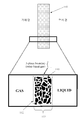
도 1(종래 기술)은, 현재 산업계에서 널리 사용된 것과 같이, 통상적인 3D 미립자 고정층 전극 또는 기체 확산 전극(GDE)(110)을 개략적인 형태로 묘사한다.Figure 1 (prior art) depicts a conventional 3D particulate immersion electrode or gas diffusion electrode (GDE) 110 in schematic form, as is widely used in the industry at present.
통상적인 3D 미립자 고정층 전극 또는 GDE(110)에서, 전도성 요소(예를 들어, 탄소 입자)는 비 전도성, 소수성 요소(예를 들어, 폴리테트라플루오로에틸렌 (PTFE) TeflonTM 입자) 및 촉매와 단일, 고정층 구조(110)로 통상적으로 (압축 / 소결을 사용하여) 결합된다. 고정층 구조(110)는 중간 소수성, 우수하나 최고가 아닌 이용가능한 전도성 및 단일 지역(113) 위에서 비-균일하고 약하게 형성된 구멍 구조를 가진다. 3D 미립자 고정층 전극 또는 GDE(110)가 한쪽에서 액체 전해질과 접촉되고 다른 쪽에서 기체 물질과 접촉될 때, 이런 물리적 형태는, 도 1에 제공된 확대도로 예시된 대로, 외부 표면(112) 아래 및 단일 지역(113) 내에, 전극(110)의 바디 내에 불규칙적으로 분포된 3상 고체-액체-기체 경계의 형성을 초래한다. 3상 경계에서, 전기적으로 연결된 촉매(고체상)는 반응물(액체 또는 기체상) 및 생성물(액체 또는 기체상의 다른 하나)과 동시에 접촉하고 있다. 따라서 GDE(110) 내의 고체-액체-기체 경계는 전기화학적 액체-대-기체 또는 기체-대-액체 반응이, 예를 들어, 특정 전압의 인가에 의해 촉진될 수 있는 경계를 제공한다. 3상 고체-액체-기체 경계의 육안으로 보이는 폭은 통상적인 GDE의 폭과 치수가 필적하거나 유사하다. 통상적인 GDE에서 3상 고체-액체-기체 경계의 두께는 통상적으로 연료 전지 GDE에서 0.4mm 내지 0.8mm의 범위이며, 산업적 전기화학 GDE에서 수 밀리미터와 같이 더 큰 두께이다.In a typical 3D particulate fixed bed electrode or
상기 기술된 플러딩 현상은 물이 임의의 종류의 외부 압력을 받는 경우 기체 확산 전극으로의 물 침투에 의해 주로 발생된다. 예를 들어, 1 미터 높이의 산업용 전해질 전지에서, 연료 전지의 바닥에서의 물은 물의 수두(hydraulic head)로 인해 0.1 bar로 가압된다. 만약 GDE가 이 깊이에서 사용되는 경우, GDE는 일반적으로 물 침투에 의해 바로 플러딩될 것이며 이는 현재 GDE가 (비록 WO2013037902에서 0.2 bar의 습윤 압력을 가지는 GDE가 최근 보고되었을지라도) 일반적으로 0.1 bar 미만인 매우 낮은 ("물 진입 압력( water entry pressure )"으로도 알려진) "습윤 압력"을 가지기 때문이다. 추가적으로, GDE는 상대적으로 비싸다.The flooding phenomenon described above is mainly caused by water infiltration into the gas diffusion electrode when the water receives any kind of external pressure. For example, in a 1 meter high industrial electrolytic cell, the water at the bottom of the fuel cell is pressurized to 0.1 bar due to the water's hydraulic head. If GDE is used at this depth, the GDE will generally be flooded immediately by water penetration, which means that the present GDE (although GDE with a wetting pressure of 0.2 bar in WO2013037902 is recently reported) is generally less than 0.1 bar low ( "water entry pressure (water entry pressure), because ", also known as)" have a wet pressure ". Additionally, GDE is relatively expensive.
이는 전극에서의 GDE의 사용을 통해 산소 또는 수소와 같은 기체를 카운터 전극에 적용하는 것이 매우 이익이 되는 산업용 전기화학 전지들에서 특히 문제이다.This is particularly problematic in industrial electrochemical cells where it is very advantageous to apply a gas such as oxygen or hydrogen to the counter electrode through the use of GDE at the electrode.
감극Decay
여러 산업용 전기화학 방법들에서, 카운터 전극은 카운터 전극이 원하는 귀중한 생성물을 생산하지 않기 때문에 생산적이지 않다. 대신, 카운터 전극은 일반적으로 어느 정도의 비용으로 제거되어야만 하는 폐기물을 생산한다. 이러한 경우들에서, 당업자는 산소 또는 수소와 같은 기체를 그 전극의 표면에 도입함으로써 카운터-전극을 "감극"할 수 있으며, 따라서 전극에서 발생하는 반쪽 반응을 변화시키며 이론적인 전체 전지 전압을 약 1.2 V만큼 감소시킨다.In many industrial electrochemical methods, the counter electrode is not productive because the counter electrode does not produce the desired valuable product. Instead, the counter electrode generally produces waste that must be removed at some cost. In such cases, those skilled in the art will be able to " depolarize " the counter-electrode by introducing a gas such as oxygen or hydrogen into the surface of the electrode, thereby changing the half reaction occurring at the electrode, V.
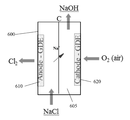
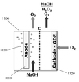
예를 들어, 세계에서 널리 사용되는 산업용 전기-합성 방법들 중 하나인 전통적인 클로르-알칼리 방법에서, 산성화된 25% NaCl 용액으로부터의 애노드에서 염소가 생성되는 한편, 강한 부식성 용액(일반적으로 32% NaOH)으로부터의 캐소드에서 수소가 생성된다. 수소는 원하지 않으며 제거되어야만 한다. 전극 반쪽-반응들은 다음과 같다:For example, in a traditional chlor-alkali process, one of the most widely used industrial electro-synthesis methods in the world, chlorine is produced in the anode from an acidified 25% NaCl solution while a strong corrosive solution (generally 32% NaOH ≪ / RTI > Hydrogen is not desired and must be removed. Electrode half-reactions are as follows:
애노드에서: 2Cl- → Cl2 + 2e- E0 ox = -1.36 VAt the anode: 2Cl - → Cl 2 + 2e - E o ox = -1.36 V
캐소드에서: 2H2O + 2e- → H2 + 2OH- E0 red = -0.83 VAt the cathode: 2H 2 O + 2e - → H 2 + 2OH - E 0 red = -0.83 V
------------------ ------------------
E0 전지 = -2.19 VE 0 battery = -2.19 V
E전지의 경우 마이너스 부호는 전체 반응이 열역학적으로 선호되지 않는 것을 나타내며 외부 전압의 적용에 의해 움직여질 필요가 있다. E전지에 대한 플러스 부호는 전체 반응이 자발적이며 전압 및 전류를 생성하는 것을 나타낼 것이다. 즉, 이는 전지가 연료 전지로서 역할할 것을 나타낼 것이다.For the E battery , the minus sign indicates that the overall reaction is not thermodynamically favored and needs to be actuated by the application of an external voltage. The plus sign for the E battery will indicate that the overall reaction is spontaneous and produces voltage and current. That is, this will indicate that the battery serves as a fuel cell.
전통적인 클로르-알칼리 방법에서의 캐소드가 생산적이지 않기 때문에, 이는 산소 기체의 첨가에 의해 감극되어야만 하며 따라서 실질적으로 전체 전지 전압을 감소시킨다. 산소 기체는 캐소드에서의 기체 확산 전극(GDE)을 사용하고 GDE를 통해 산소를 시스템으로 통과시킴으로써 가장 효과적으로 도입된다.Since the cathodes in the traditional chlor-alkali process are not productive, they must be reduced by the addition of oxygen gas and thus substantially reduce the overall cell voltage. Oxygen gas is most effectively introduced by using a gas diffusion electrode (GDE) at the cathode and passing oxygen through the system to the system.
전극 반쪽-반응들은 다음과 같을 것이다:Electrode half-reactions will be as follows:
애노드에서: 2 Cl- → Cl2 + 2e- E0 ox = -1.36 VAt the anode: 2 Cl- → Cl2 + 2e- E0 ox = -1.36 V
캐소드에서: O2 + 2 H2O + 4e- → 4OH- E0 red = 0.40 VAt the cathode: O 2 + 2 H 2 O + 4e- → 4OH - E 0 red = 0.40 V
--------------------- ---------------------
E0 전지 = -0.96 VE 0 Battery = -0.96 V
상기한 바와 같이, 이러한 방식에서 캐소드의 산소 감극은 전지 전압을 절반 넘게 감소시키며, 따라서 염소의 제조에 수반되는 에너지 소비에서의 상당한 향상에 영향을 미친다.As described above, in this manner, oxygen cathodic reduction of the cathode reduces the cell voltage by more than half, thus influencing a significant improvement in the energy consumption associated with the production of chlorine.
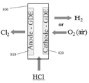
현재, GDE는 카운터 전극들을 감극하기 위한 목적으로 단지 소수의 산업적 적용들에서 통합된다. 이는 주로 Industrie De Nora S.p.A., Bayer AG, 및 ThyssenKrupp Uhde AG 회사들에 의해 염산으로부터의 염소의 생산을 수반한다.Currently, the GDE is integrated in only a few industrial applications for the purpose of depolarizing the counter electrodes. This is mainly accompanied by the production of chlorine from hydrochloric acid by Industrie De Nora S.p.A., Bayer AG, and ThyssenKrupp Uhde AG.
전극 감극에 유리할 수 있는 대부분의 산업용 전기화학 방법들은 현재 전극 감극을 사용하지 않는다. 이는 주로 비싸고 통상적인 GDE를 사용하는 것의 실제적인 어려움들 때문이다.Most industrial electrochemical methods that can benefit from electrode decay do not currently use electrode decoupling. This is mainly due to the practical difficulties of using the expensive and common GDE.
예를 들어, 클로르-알칼리 전지들은 일반적으로 높이가 1 미터를 초과한다. 만약 전지의 하나의 벽을 포함하는 통상적인 GDE가 애노드를 감극하기 위해 사용되는 경우, GDE는 GDE의 기부에서 플러드할 것이어서 매우 부식성인 32% NaOH 용액을 전지의 전해질 챔버로부터 누출시킬 것이다. 오늘날, 통상적인 GDE는 일반적으로 0.1 bar 액체 압력에서 플러드하기 때문에 이는 발생할 것이다. 결과적으로, 이러한 전지들에서 오늘날 통상적인 GDE를 사용하는 것은 적합하지 않다.For example, chlor-alkali batteries generally have a height exceeding one meter. If a conventional GDE containing a single wall of the cell is used to degrade the anode, the GDE will flood at the base of the GDE and will leak a very corrosive 32% NaOH solution from the electrolyte chamber of the cell. Today, this will happen because conventional GDEs generally flood at 0.1 bar liquid pressure. As a result, it is not appropriate to use conventional GDEs in these cells today.
이러한 문제점을 극복하기 위한 시도들이 이루어졌다. 예를 들어, WO2003035939는 전해질 챔버로부터 부식성 전해질의 누출 없이 캐소드에서의 산소의 도입을 가능하게 해주는 다소의 크고 무거운 "기체 주머니" 디자인의 전극의 사용을 교시한다. WO2003042430은 액체 챔버들에서 수두(hydraulic head)를 효율적으로 부수나 비싸며 전지 구조에 저항 강하(ohmic drop)를 더하는 바람직하지 않은 특성들을 가지는 "퍼컬레이터 형태" 캐소드의 사용에 의해 문제점을 극복하는 것을 유사하게 추구한다.Attempts have been made to overcome these problems. For example, WO2003035939 teaches the use of electrodes of somewhat larger and heavier " gas pocket " designs that allow the introduction of oxygen at the cathode without leakage of corrosive electrolytes from the electrolyte chamber. WO2003042430 discloses that overcoming the problem by using a " perchelator type " cathode with undesirable properties that effectively breaks or expels the hydraulic head in liquid chambers and adds an ohmic drop to the cell structure, .
보다 최근에, 전극 전문 회사인 Industrie De Nora S.p.A.에 양도된 WO2013037902는 1 미터 수두 하에서의 물에 의해 생성된 0.1 bar 압력을 초과하는 0.2 bar 액체 압력을 견딜 수 있는 GDE를 구현하는 신규한 제조 기술을 기재한다. WO2013037902에 기술된 GDE는 그럼에도 불구하고 비싸며 단지 0.1 bar 초과 압력이 매우 부식성인 전해질을 전지의 전해질 챔버로부터 누출하는 것을 유발하기에 충분하다는 면에서 오차 범위를 거의 남기지 않는다. - 얼마나 작던지 간에 - GDE에서의 임의의 결함들은 부식제 누출의 위험을 초래 또는 생성할 것이다. 더욱이, 압력의 균형을 이루기 위해 특수한 매니폴딩이 전지에 필요하다.More recently, WO2013037902, assigned to Electrode specialist company Industrie De Nora SpA, discloses a novel fabrication technique embodying GDE capable of withstanding 0.2 bar liquid pressure exceeding 0.1 bar pressure produced by water under 1 meter head do. The GDE described in WO2013037902 nevertheless leaves very little margin of error in that it is expensive and is sufficient to cause the electrolyte to leak out of the electrolyte chamber of the cell only when the pressure exceeding 0.1 bar is highly corrosive. Whatever the case may be - any flaws in the GDE will create or create a risk of caustic leaks. Moreover, special manifolding is required for the cell to balance pressure.
현실적으로 실행 가능했을 경우, 기체 감극된 GDE의 사용으로 인해 이익을 얻을 수 있는 여러 다른 산업용 전기화학 방법들에서 유사한 또는 필적하는 상황들 또는 문제들이 존재한다. 이들은 (a) 과산화수소, (b) CO2로부터의 연료, (c) 오존, (d) 부식제(염소가 없음), (e) 과망간산칼륨, (f) 염소산염, (g) 과염소산염, (h) 불소, (i) 브롬, (j) 과황산염, 및 다른 것들의 전기화학적 제조를 포함한다. 금속 전해 채취와 같은 전기야금 응용들은 또한 애노드 감극과 관련된 에너지 절약으로 인해 이익을 얻을 수 있다; 금속 전기-증착은 이러한 전지들의 캐소드 면에서 일어나는 한편, 산소는 애노드에서 발생한다. 만약 산소 발생이 적절한 기체 확산 애노드상의 수소 산화에 의해 교체되는 경우, 이는 상당한 에너지 절약을 발생시킬 것이다. 하지만, 통상적인 GDE의 기계적 특징들은 이들을 좁은-갭 챔버들의 경계를 정하는 것에 부적절하게 만들어, 전기야금 방법들에서 널리 사용되는 분리되지 않은 전기 분해 전지들에서의 이들의 적용을 제한한다. 더욱이, 통상적인 GDE는 산업용 크기의 전해조들에서 일반적으로 사용되는 전해질 용액들의 수두 하에서 누출될 것이다. 펄프 및 종이 산업에서의 여러 산업용 전기화학 방법들이 또한 (a) "흑 액" 전기분해, (b) "톨유 회수" 및 (c) 염화물 제거 전기분해를 포함하는 기체 감극된 GDE의 사용으로 인해 이익을 얻을 것이다. 심지어 매우 온화한 액체 압력들의 축적 이후의 GDE의 플러딩은 또한 수소-산소 연료 전지들과 같은 연료 전지들에서 까다로우며 잘 인식된 문제이다.There are similar or comparable situations or problems in many other industrial electrochemical methods that could benefit from the use of gas-scavenged GDEs if practically feasible. These are: (a) hydrogen peroxide, (b) fuel from CO 2 , (c) ozone, (d) corrosive (without chlorine), (e) potassium permanganate, (f) chlorate, (g) perchlorate, Fluorine, (i) bromine, (j) and sulfate, and others. Electro-metallurgical applications such as metal electrolytic harvesting can also benefit from energy savings associated with anode depletion; Metal electro-deposition occurs at the cathode side of these cells while oxygen occurs at the anode. If oxygen evolution is replaced by hydrogen oxidation on a suitable gas diffusion anode, this will result in significant energy savings. However, the mechanical properties of conventional GDE make them unsuitable for delimiting narrow-gap chambers, limiting their application in discrete electrolytic cells, which are widely used in electro-metallurgical methods. Moreover, conventional GDE will leak under the head of electrolyte solutions commonly used in industrial size electrolytic baths. Several industrial electrochemical methods in the pulp and paper industry are also beneficial because of the use of gas-scaled GDE, including (a) " black liquor " electrolysis, (b) " tall oil recovery " and (c) . Even the flooding of GDE since the accumulation of very mild liquid pressures is also a tricky and well recognized problem in fuel cells such as hydrogen-oxygen fuel cells.
요약하면, 기체 감극될 수 있으며 전기-합성, 전기화학, 연료 및/또는 전기-에너지 전지들 또는 장치들에 사용될 수 있는 기체 확산 전극에 대한 필요가 존재한다. 바람직하게, 기체 확산 전극은 상대적으로 저렴하며, 강하고 및/또는 기계적으로 강해야 하며, 상대적으로 높은 습윤 압력을 가져야 한다. 결과적으로 여러 가지 산업용 전기화학, 연료, 전기-에너지 및/또는 전기-합성 방법들, 전지들 및/또는 장치들에서 기체 확산 및 기체 감극 전극으로 쉽고, 일반적이며, 및/또는 유익하게 배치될 수 있는 이러한 기체 확산 전극들에 대한 필요가 존재한다.In summary, there is a need for gas diffusion electrodes that can be gas depolarized and can be used in electro-synthetic, electrochemical, fuel and / or electro-energy cells or devices. Preferably, the gas diffusion electrode is relatively inexpensive, strong and / or mechanically strong, and has a relatively high wetting pressure. As a result, can be easily, generically, and / or advantageously disposed of as gas diffusion and gas decaying electrodes in a variety of industrial electrochemical, fuel, electric-energy and / or electro-synthetic methods, batteries and / There is a need for such gas diffusion electrodes.
본 명세서에서 임의의 종래 출판물 (또는 이로부터 유래된 정보), 또는 공지된 임의의 문제에 대한 참조는, 본 명세서가 관련된 노력의 분야에서 종래 출판물 (또는 이로부터 유래된 정보), 또는 공지된 문제가 공통의 일반적인 지식의 일부를 형성한다는 인정 또는 승인 또는 임의의 형태의 제안이 아니며, 그렇게 받아들여져서는 안 된다. References herein to any conventional publications (or information derived therefrom), or to any known problem, are incorporated herein by reference in the context of an effort involving the present disclosure to conventional publications (or information derived therefrom) Is not an acknowledgment or endorsement or any form of proposal that it forms part of a common general knowledge, and should not be so accepted.
본 발명은 상기한 문제점을 해결하는 것을 그 과제로 한다.SUMMARY OF THE INVENTION The present invention has been made to solve the above problems.
이 설명은 실시예에서 하술되는 단순화된 형태에서 개념의 선택을 도입하기 위해 제공된다. 이 설명은 청구된 대상 발명의 주요 특징 또는 필수적인 특징 전부를 확인하기 위해 의도된 것이 아니며, 청구된 대상 발명의 범위를 제한하기 위해 사용되는 것으로 의도된 것도 아니다. This description is provided in order to introduce a selection of concepts in the simplified form which will be described later in the embodiment. This description is not intended to identify all of the essential features or essential features of the claimed subject matter, nor is it intended to be used to limit the scope of the claimed subject matter.
한 예시적 양태에서, 전극, 바람직하게는 기체 감극될 수 있는 기체 확산 전극(GDE)이 제공된다. 바람직하게는, 기체 확산 전극은 상대적으로 저렴하고, 튼튼하며 및/또는 기계적으로 강하고, 상대적으로 높은 습윤 압력을 가진다. 기체 확산 전극의 실시태양은, 결과적으로, 다양한 산업적 전기화학, 연료, 전기-에너지 및/또는 전기-합성 방법, 전지 및/또는 장치에서 기체 확산 전극 및/또는 기체 감극 전극으로 쉽고, 일반적이고 및/또는 유익하게 사용될 수 있다.In one exemplary embodiment, an electrode, preferably a gas diffusion electrode (GDE), which can be gas depressurized, is provided. Preferably, the gas diffusion electrode is relatively inexpensive, robust and / or mechanically strong, and has a relatively high wetting pressure. Embodiments of gas diffusion electrodes are consequently easy, common, and economical as gas diffusion electrodes and / or gas decaying electrodes in a variety of industrial electrochemical, fuel, electric-energy and / or electro-synthetic processes, batteries and / / Or may be beneficially used.
또 다른 실시 태양에서, 기체 감극될 수 있는 하나 이상의 전극들을 가지는 전기화학 전지 또는 연료 전지와 같은 전기-합성 또는 전기-에너지 전지들이 제공된다. 다른 예시적인 양태들에서, 실시태양들은 예를 들어, 전기화학 전지들 또는 장치들, 연료 전지들, 또는 일반적인 전기-에너지 또는 전기-합성 전지들 또는 장치들에서 기체 소비 또는 발생 애노드 또는 캐소드로서 기체 감극될 수 있는 기체 확산 전극들의 응용들 또는 사용들에 대한 것이다.In another embodiment, electrochemical or electro-energy cells are provided, such as an electrochemical cell or a fuel cell, having one or more electrodes that can be degassed. In other exemplary aspects, embodiments may include, for example, gas consumption or generation in electrochemical cells or devices, fuel cells, or common electro-energy or electro-composite cells or devices, And applications or uses of gas diffusion electrodes that can be depolarized.
한 실시 형태에서, 현재 실시태양들의 예시적인 3D 전극들 또는 GDE는 이들이 3D 전극 또는 GDE의 주요 특징들을 두 개 또는 적어도 개의 구별되는 지역들로 분리한다는 점에서 통상적인 미립자 고정층 GDE와 구별되며, 이들 특성들의 각각이 통상적인 GDE의 단일 바디 내에서 가능한 것보다 더 향상되며 보다 완전하게 제어될 수 있다. 이러한 3D 전극 또는 GDE의 예시적 실시태양은 이의 촉매 능력들 및 전도성에 대해 향상된 또는 최적화된 촉매를 또한 선택적으로 포함할 수 있는 액체-및-기체-다공성 전도성 물질을 포함할 수 있다. 전도성 물질은 예를 들어, 소수성일 수 있으며, 기체 운송 특성들에 대해 공극 구조가 선택되고, 향상되며 또는 최적화되는 전극의 일반적인 작동 사용 동안 비전도성이며 액체 전해질 불투과성인 기체 투과성 물질에 부착되거나, 연결되거나, 접촉하거나, 인접하게 위치되거나, 또는 접한다. 일반적인 작동 사용은 예를 들어, 전극이 의도되고 플러드되지 않는 것으로 기능하는 경우이다. 한 예에서, 기체 투과성 물질의 표면은 다공성 전도성 물질을 대면한다. 기체 투과성 물질의 표면은 다공성 전도성 물질에 닿거나 또는 접촉할 수 있으나 필수적인 것은 아니며, 예를 들어, 하나 이상의 촉매들을 포함할 수 있는 매개 바인더 물질 또는 층이 존재할 수 있다. 기체 투과서성 물질의 표면 또는 표면 근처는 기체 투과성 물질 및 다공성 전도성 물질의 계면 또는 경계 지역이다. 전극이 사용되는 경우, 3상 고체-액체-기체 경계가 다공성 전도성 물질을 대면하는 기체 투과성 물질의 표면 또는 표면 근처에서 형성될 수 있다. 본 발명에서, 표면 "에서 또는 근처"는 바인더 물질의 두께인 거리 내(존재하는 경우, 및 본 발명에서 논의된 대로), 또는 3상 고체-액체-기체 경계 그 자체의 거시적 폭인 거리 내, 또는 기체 투과성 물질 및 다공성 전도성 물질의 임의의 중첩 거리 내, 또는 다공성 전도성 물질의 폭인 거리 내를 의미하는 것으로 의도된다. 3상 고체-액체-기체 경계는 정확히 표면'에서' 형성할 필요는 없지만, 가까운, 이웃하는, 접하는, 바로 옆의 또는 내의, 또는 근접의 의미에서 표면 '근처'에서 형성할 수 있다. 3상 고체-액체-기체 경계는 과도한 기체 또는 액체 압력의 적용에 의해 추가로 이동할 수 있지만, 경계는 일반적인 작동 사용 동안 기술된 표면에 대해 '근처'에 존재할 것이다.In one embodiment, exemplary 3D electrodes or GDEs of current embodiments are distinguished from conventional microparticle immobilization GDEs in that they separate the main features of the 3D electrode or GDE into two or at least distinct regions, Each of the properties can be improved and more fully controlled than is possible in a single body of a conventional GDE. Exemplary embodiments of such 3D electrodes or GDEs may include liquid-and-gas-porous conductive materials that may optionally also include an improved or optimized catalyst for their catalytic capabilities and conductivity. The conductive material may be, for example, hydrophobic and may be attached to a gas permeable material that is nonconductive and liquid electrolyte impermeable during normal operation of the electrode where the void structure is selected, enhanced or optimized for gas transport properties, Connected, contacted, positioned adjacent, or tangent. Typical operational uses are, for example, when the electrode functions as intended and not flooded. In one example, the surface of the gas permeable material faces the porous conductive material. The surface of the gas permeable material may contact or contact the porous conductive material but is not essential, for example, there may be an intermediate binder material or layer that may comprise one or more catalysts. The surface or near the surface of the gas permeable material is the interface or boundary region of the gas permeable material and the porous conductive material. When an electrode is used, a three-phase solid-liquid-gas interface can be formed near the surface or surface of the gas-permeable material facing the porous conductive material. In the present invention, "at or near" the surface is within a distance that is the thickness of the binder material (if present and as discussed herein) or within the distance of the macroscopic width of the three-phase solid- Is intended to mean within any overlap distance of the gas permeable material and the porous conductive material, or within a distance that is the width of the porous conductive material. The three-phase solid-liquid-gas interface need not be formed exactly at the surface, but can be formed in the vicinity of, near, neighboring, tangential, inward or inward, or in proximity to the surface. Although the three-phase solid-liquid-gas interface can be further moved by application of excessive gas or liquid pressure, the boundary will be " near " to the surface described during normal operation use.
바람직하게, 두 개의 지역들(다공성 전도성 물질을 포함하는 제 1 지역 및 비전도성 기체 투과성 물질을 포함하는 제 2 지역)은 비록 이들이 인접하거나, 접하거나, 접촉하거나 또는 서로 붙어있어서 계면 또는 경계 지역 또는 가능한 중첩이 존재하더라도, 실질적으로 구별되거나 경계가 정해지거나 또는 분리된다.Preferably, the two regions (the first region comprising the porous conductive material and the second region comprising the nonconductive gas permeable material) are in contact with each other, even if they are adjacent, abutting, contacting, Although possible overlaps exist, they are substantially differentiated, delimited, or separated.
이러한 예시적 실시태양에서, 비전도성, 액체 전해질 불투과성 또는 소수성, 기체 투과성 물질은 통상적인 GDE에서 달성될 수 있는 것보다 보다 잘 정의되고, 보다 균일하고 더 작은 평균 크기의 공극들을 가진다. 바람직하게는 촉매를 구비한 액체-및-기체-다공성 컨덕터는 통상적인 GDE보다 전도성일 수 있는 한편, 이의 낮은 소수성은 일반적인 작동 조건들 하에서 액체 전해질로 완전히 또는 실질적으로 완전히 채워진 다공성 컨덕터를 볼 수 있어서, 촉매작용을 향상시키거나 최대로 촉진한다. 대조적으로, 바람직한 형태에서, 비전도성, 소수성, 기체 투과성 물질의 높은 소수성은 일반적으로 대기압에서 액체 전해질이 완전히 빈 또는 실질적으로 빈 기체 투과성 물질을 볼 것이어서, GDE 안으로의 및 바깥으로의 기체 운송을 향상시키거나 또는 최대로 촉진한다.In this exemplary embodiment, the nonconductive, liquid electrolyte impermeable or hydrophobic, gas permeable material has better defined, more uniform and smaller average size voids than can be achieved with conventional GDE. Preferably, the liquid-and-gas-porous conductor with the catalyst can be more conductive than the conventional GDE, while its low hydrophobicity can be seen by the porous conductor completely or substantially completely filled with the liquid electrolyte under normal operating conditions , Which improves or maximizes catalysis. In contrast, in a preferred form, the high hydrophobicity of the non-conductive, hydrophobic, gas permeable material generally improves gas transport into and out of the GDE, because at ambient pressure the liquid electrolyte will be completely empty or substantially empty gas permeable material Or to maximize.
이러한 예시적 실시태양 3D 전극 또는 GDE가 액체 전해질에 의해 전도성 면 상 및 기체 물질에 의해 비전도성 면 상에서 접촉하는 경우, 상기 물리적 특징들은 다공성 전도성 물질을 대면하는 기체 투과성 물질 표면 또는 근처에서 3상 고체-액체-기체 경계의 형성을 유발하며, 이는 또한 두 개의 구별되는 지역들 사이의 계면에서 존재할 수 있다. 이 경계는 통상적인 GDE에서의 3상 고체-액체-기체 경계와는 매우 다르다. 이는 통상적인 GDE에서 달성될 수 있는 것보다 잘 정의되고, 보다 좁으며, 보다 안정하고 및/또는 보다 강하다는 점에서 다르다. 따라서, 바람직한 실시태양의 작동에서, 3상 고체-액체-기체 경계는 다공성 전도성 물질을 대면하는 기체 투과성 물질의 표면에서 또는 표면 근처에서 형성된다(이는 또한 계면, 또는 다공성 전도성 물질의 경계 지역에서 존재할 수 있으며, 촉매, 및 비전도성 기체 투과성 물질을 포함할 수 있다). 이는 예를 들어, 전극의 폭 또는 두께와 비교하여 상대적으로 좁은 거시적 폭을 가지는 3상 고체-액체-기체 경계를 제공한다.When this exemplary embodiment 3D electrode or GDE is contacted by a liquid electrolyte on a conductive surface and on a nonconductive surface by a gaseous material, the physical characteristics may include a three-phase solid - liquid-gas boundary, which may also be present at the interface between two distinct regions. This boundary is very different from the three-phase solid-liquid-gas boundary in conventional GDE. Which differs in that it is well defined, narrower, more stable and / or stronger than can be achieved in conventional GDE. Thus, in the operation of the preferred embodiment, a three-phase solid-liquid-gas interface is formed at or near the surface of the gas permeable material facing the porous conductive material (which also exists at the interface, or at the boundary of the porous conductive material And may include a catalyst, and a non-conducting gas permeable material. This provides, for example, a three-phase solid-liquid-gas interface with a relatively narrow macroscopic width compared to the width or thickness of the electrode.
본 발명자들은 예시적 실시태양 3D 전극들 또는 GDE가 두 개의 지역들의 계면에서 또는 계면 근처에서 향상된 또는 최적의 공극 구조, 예를 들어 향상된 또는 최적의 전도성이며, 향상된 또는 최대 촉매 구조를 가지는 향상된 또는 최대 기체 운송을 촉진하는 소수성 공극 구조를 제공할 수 있다는 것을 발견하였기 때문에 이들 특징들은 중요하다. 효과에 있어서, 예시적 실시태양 3D 전극들 또는 GDE에서의 3상 고체-액체-기체 경계에서 기체 확산 전극의 주요 특성들의 각각은 그렇지 않은 것들보다 이상적으로 만들어질 수 있거나 또는 적어도 이상적인 것에 보다 가까울 수 있다.The present inventors have found that the exemplary embodiments 3D electrodes or GDE have an enhanced or optimal pore structure at the interface or near the interface of two regions, such as enhanced or optimized conductivity, enhanced or maximum These features are important because they have been found to provide a hydrophobic pore structure that promotes gas transport. In effect, each of the key properties of the gas diffusion electrode at the three-phase solid-liquid-gas interface at the exemplary embodiments 3D electrodes or GDE can be made more ideal than not, or at least closer to ideal have.
본 발명자들은 이러한 향상 또는 최적화의 효과가 놀랍고 현저한 전기화학 성능을 나타낸다는 것을 추가로 발견하였다. 보다 좁고 2차원(2D), 또는 실질적으로 2D, 거시적 기하학처럼 보이는 것에 국한된 3상 고체-액체-기체 경계에도 불구하고, 예시적 실시태양 3D 전극들 또는 GDE에서의 3상 고체-액체-기체 경계의 전기화학 능력들은 실질적으로 통상적인 GDE의 것들보다 향상되며, 실제로 훨씬 뛰어넘는다. 이러한 3상 고체-액체-기체 경계들은 예를 들어, 예시적 실시태양 3D 전극들 또는 GDE에 예상치 못한 범위 및 다음을 포함하는 신규한 전기화학 능력들을 부여할 수 있다:The present inventors have further found that the effect of such an enhancement or optimization represents surprising and remarkable electrochemical performance. Despite a three-phase solid-liquid-gas boundary confined to a narrower, two-dimensional (2D), or substantially 2D, macroscopic geometry, three-phase solid-liquid-gas boundaries in the exemplary embodiments 3D electrodes or GDE Of the electrochemical capacities are substantially better than those of the conventional GDE and actually far exceed those of the conventional GDE. These three-phase solid-liquid-gas boundaries can, for example, impart unexpected ranges to the exemplary embodiments 3D electrodes or GDE and novel electrochemical capabilities including:
1. 통상적인 GDE에서 달성될 수 있는 것보다 훨씬 높은 습윤 압력들 및 기포점들. "습윤 압력"은 액체 전해질이 GDE를 관통하고 플러드하는 GDE의 기체 면에 대하여 GDE의 액체 전해질 면 상의 압력의 가장 낮은 과량으로 정의된다. "기포점"은 기체가 GDE를 통해 들어가며 액체 전해질 면 상의 전극 표면에서 거품들을 형성하는 GDE의 액체 전해질 면에 대하여 GDE의 기체 면 상의 압력의 가장 낮은 과량으로 정의된다. 예시적 실시태양 GDE는 일반적으로 0.2 bar 초과의 습윤 압력들 및 기포점들을 가지는 반면, 통상적인 GDE는 일반적으로 0.2 bar 이하의 습윤 압력들 및 기포점들을 가진다; 1. Much higher wetting pressures and bubble points than can be achieved with conventional GDE. " Wetting pressure " is defined as the lowest excess of pressure on the liquid electrolyte surface of the GDE relative to the gas face of the GDE through which the liquid electrolyte penetrates and floods the GDE. The " bubble point " is defined as the lowest overpressure of the gas phase surface of the GDE with respect to the liquid electrolyte surface of the GDE entering the gas through the GDE and forming bubbles at the electrode surface on the liquid electrolyte surface. Exemplary embodiments GDE generally has wet pressures and bubble points of greater than 0.2 bar, while conventional GDE generally has wet pressures and bubble points of less than 0.2 bar;
2. 특히, 하지만 이에 제한되지 않는, 상대적으로 낮은 전류 밀도들에서 작동되는 경우, 통상적인 GDE에서 구현되는 것보다 낮은 전기 저항, 보다 높은 전기촉매적 활성들 및 반응성들은 물론, 사용되는 경우, 촉매 물질들의 보다 효율적인 활용; 및 2. Operating at relatively low current densities, particularly, but not limited to, lower electrical resistance than that implemented in conventional GDE, Higher electrocatalytic activities and reactivities, as well as more efficient utilization of catalytic materials, if used; And
3. 지금까지 도달할 수 없었던 기체-대-액체 또는 액체-대-기체 전기화학 반응들을 촉진하는 또는 특히, 하지만 이에 제한되지 않는, 상대적으로 낮은 전류 밀도들에서 작동되는 경우, 적어도 지금까지 실질적으로 실행가능한 것으로 입증되지 않았던 전기화학 반응들을 향상시키는 겉보기 용량.3. When operated at relatively low current densities that promote, or in particular, but not limited to, gas-to-liquid or liquid-to-gas electrochemical reactions that have never been attained so far, Apparent capacity to improve electrochemical reactions that have not been proven to be.
따라서, 특정 예들에서, 이러한 3D 전극들 또는 GDE는 독특하고 대단히 뚜렷하고, 좁고, 안정하고, 및/또는 강한 3-방향 고체-액체-기체 계면을 보여준다. 이러한 계면에 의해 형성된 하나의 효과는 고품질의 액체-고체-기체 계면으로부터 얻은 대단히 높은 전기화학 및 촉매적 활성이다. 예를 들어, 본 발명자들은 본 실시태양들의 예시적인 GDE가 산소가 대기의 단 20%를 차지함에도 불구하고 대기로부터 자발적이며, 공격적이며, 선택적으로 산소를 격리시키는 것을 관찰하였다. 따라서, 이러한 형태의 예시적인 GDE는 지금까지 가능했던 것들보다 다우 휴론 방법을 보다 전기적 및 경제적으로 효율적인 방식으로 촉진하기 위해 사용될 수 있다. 유사하게, 예시적인 GDE가 실온 직접 메탄 연료 전지에서 일어나는 지금까지 알려지지 않았던 반응들을 촉진할 수 있는 것으로 증명되었다.Thus, in certain instances, such 3D electrodes or GDEs exhibit a unique and very distinct, narrow, stable, and / or strong three-way solid-liquid-gas interface. One effect formed by this interface is the extremely high electrochemical and catalytic activity obtained from a high quality liquid-solid-gas interface. For example, the present inventors have observed that the exemplary GDEs of these embodiments spontaneously, aggressively, and selectively sequester oxygen from the atmosphere despite oxygen accounting for only 20% of the atmosphere. Thus, an exemplary GDE of this type can be used to facilitate the Dow hurron method in a more electrically and economically efficient manner than was possible so far. Similarly, it has been demonstrated that the exemplary GDE can promote previously unknown reactions occurring in room temperature direct methane fuel cells.
이들 개선들은 통상적인 GDE에 비해 예상치 못했던 향상들을 제공한다. 이들은 현재 업계에서 사용되는 통상적인 미립자 고정층 GDE의 제조가 단일 물질 내에 동시의 중요한 물리적 특성들의 전부를 만드는 것에 근거하기 때문에 일어나는 것으로 보인다. 이러한 접근은 GDE의 주요 특성들(즉: 공극 구조, 소수성, 기체 운송, 액체 운송, 전도성 및 촉매적 활성)이 일반적으로 상호의존적이라는 사실을 실질적으로 무시하며, 따라서 단일 물질 내에 준비된, 동시에 발생하는 개선 또는 최적화에 열려있지 않다. 본 발명에 기술된 예시적 실시태양 GDE는 이러한 한계를 고려하며 하나 이상의 주요 특성들을 개별적으로 최적화하여, 두 개의 구별된 지역들의 계면에서 보다 이상적인 전체 특성을 달성한다.These improvements provide unexpected improvements over conventional GDE. These appear to occur because the manufacture of conventional particulate fixed bed GDEs currently used in the industry is based on making all of the important physical properties simultaneously in a single material. This approach substantially ignores the fact that the main characteristics of GDE (ie: pore structure, hydrophobicity, gas transport, liquid transport, conductivity and catalytic activity) are generally interdependent, It is not open for improvement or optimization. The exemplary embodiment GDE described in the present invention considers these limitations and optimizes one or more key characteristics individually to achieve a more ideal overall characteristic at the interface of two distinct regions.
본 발명자들은 예시적 실시태양 GDE가 매우 낮은 비용으로 제조될 수 있어, (i) 전기 손실을 최소화하며 전기 효율을 최대화하는 상대적으로 낮은 전류 밀도들, 및/또는 (ii) 단지 낮은 전류 밀도들에서 효율적으로 작동하는 지구상에 풍부한 원소들을 포함하는 저비용 촉매들의 실질적인 사용을 가능하게 한다는 것을 추가로 발견하였다. 이들에 의해 산업적-규모의 전기-합성 및 전기-에너지 응용들에서 사용하기 위한 실질적으로 및 경제적으로 실행 가능한 대규모 전기화학 전지들을 제조하는 것이 가능하게 되었다. 이러한 전지들은 대규모 생산 및 에너지 환경들에서 지금까지 이용할 수 없었던 에너지 효율을 달성할 수 있다. 예를 들어, 염소는 91% 에너지 효율을 가진 클로르-알칼리 방법을 사용하여 규모에서 제조될 수 있는 반면, 최대 이용가능한 산업적인 클로르-알칼리 플랜트들은 66% 에너지 효율을 달성한다.The present inventors have found that the exemplary embodiment GDE can be fabricated at a very low cost and can (i) achieve relatively low current densities that minimize electrical losses and maximize electrical efficiency, and / or (ii) Thereby enabling the practical use of low cost catalysts containing rich elements on the earth that operate efficiently. Thereby making it possible to produce large scale electrochemical cells that are practically and economically feasible for use in industrial-scale electro-composite and electro-energy applications. These cells can achieve energy efficiency that has never been available in large production and energy environments. For example, chlorine can be manufactured on a scale using a chlor-alkali process with 91% energy efficiency, while the most available industrial chlor-alkali plants achieve 66% energy efficiency.
본 발명에서 사용된 바와 같이, 3차원(3D) 전극은 효과적인 표면 영역이 전극의 기하학적 2D 표면 영역보다 큰 고체, 기체 투과성 또는 액체 통과(flow-through) 전극이다. 3D 전극들은 (증가된 효과적인 표면 영역을 사용함으로써) 3D 전극의 표면에 대한 하나 이상의 반응 물질 종들의 운송을 일반적으로 향상시키는 비평면 전극들이다. 3D 전극들에 대한 언급은 또한 통과(flow-through) 전극들 또는 다공성 전극들을 포함하는 것으로 이해되어야 한다.As used herein, a three-dimensional (3D) electrode is a solid, gas-permeable or liquid-flow electrode having an effective surface area greater than the geometric 2D surface area of the electrode. 3D electrodes are nonplanar electrodes that generally improve the transport of one or more reactive species to a surface of a 3D electrode (by using an increased effective surface area). It should be understood that reference to 3D electrodes also includes flow-through electrodes or porous electrodes.
기체 투과성 물질에 대한 언급은 임의의 형태 또는 기체 투과성 매질, 물건, 층, 막, 장벽, 매트릭스, 원소 또는 구조, 또는 이들의 조합의 형태를 포함하는 일반적인 언급으로 이해되어야 한다.Reference to a gas permeable material should be understood to be generic, including any form or form of gas permeable media, article, layer, film, barrier, matrix, element or structure, or a combination thereof.
기체 투과성 물질에 대한 언급은 또한 물질, 매질, 물건, 층, 막, 장벽, 매트릭스, 원소 또는 구조(즉 기체 투과성 물질)의 적어도 일부를 통한 또는 이들의 적어도 일부를 가로지르는 하나 이상의 기체들의 이동, 이송, 침투 또는 운송을 가능하게 하기 위해 침투할 수 있는 임의의 매질, 물건, 층, 막, 장벽, 매트릭스, 원소 또는 구조를 포함하는 것으로 이해되어야 한다. 즉, 기체 투과성 물질을 만드는 물질은 그 자체가 기체 투과성일 수 있거나 또는 기체 투과성이 아닐 수 있지만, 그 물질로 형성되거나 만들어지거나, 또는 적어도 부분적으로 형성되거나 또는 만들어진 물질, 매질, 물건, 층, 막, 장벽, 매트릭스, 원소 또는 구조는 기체 투과성이다. 기체 투과성 물질은 다공성일 수 있으며, 적어도 하나의 비-다공성 물질 및 하나의 다공성 물질의 복합체일 수 있으며, 또는 완전히 비-다공성일 수 있다. 기체 투과성 물질은 또한 "통기성" 물질로 언급될 수 있다. 임의의 제한을 가함이 없이 단지 예를 명확하게 하기 위하여, 기체 투과성 물질의 예는 다공성 매트릭스이며, 기체 투과성 물질이 만들거나 형성하는 물질의 예는 PTFE이다.Reference to a gas permeable material also includes movement of one or more gases across or through at least a portion of a material, medium, article, layer, film, barrier, matrix, element or structure (i.e., gas permeable material) Material, layer, film, barrier, matrix, element or structure that can penetrate the substrate to enable transport, penetration or transport of the substrate. That is, the material making the gas permeable material may be gas permeable per se or may not be gas permeable, but may be formed of materials, materials, materials, layers, membranes , Barriers, matrices, elements or structures are gas permeable. The gas permeable material may be porous and may be a composite of at least one non-porous material and a porous material, or may be completely non-porous. Gas permeable materials may also be referred to as "breathable" materials. An example of a gas permeable material is a porous matrix and an example of a material made or formed by a gas permeable material is PTFE in order to make the example clear without any limitation.
다공성 전도성 물질에 대한 언급은 물질, 매질, 물건, 층, 막, 장벽, 매트릭스, 원소 또는 구조(즉 다공성 전도성 물질)의 적어도 일부를 통한 또는 이들의 적어도 일부를 가로지르는 하나 이상의 기체들 및/또는 액체들의 이동, 이송, 침투 또는 운송을 가능하게 하기 위해 침투할 수 있는 임의의 매질, 물건, 층, 막, 장벽, 매트릭스, 원소 또는 구조를 포함하는 것으로 이해되어야 한다. 즉, 다공성 전도성 물질을 만드는 물질은 그 자체가 기체 및/또는 액체 투과성일 수 있거나 또는 기체 및/또는 액체 투과성이 아닐 수 있지만, 그 물질로 형성되거나 만들어지거나, 또는 적어도 부분적으로 형성되거나 또는 만들어진 물질, 매질, 물건, 층, 막, 장벽, 매트릭스, 원소 또는 구조는 기체 및/또는 액체 투과성이다. 다공성 전도성 물질은 복합 물질일 수 있으며, 예를 들어 전도성 물질, 금속성 물질의 하나의 형태보다 많게 또는 전도성 또는 금속성 물질(들) 및 비-금속성 물질(들)로 구성된다. 임의의 한정을 가하는 것이 아닌 명확하게 하기 위한 예로써, 다공성 전도성 물질들의 예들은 다공성 또는 투과성 금속들, 컨덕터들, 메쉬들, 그리드들, 격자들, 옷감들, 우븐 또는 논-우븐 구조들, 웹들 또는 다공 시트들을 포함한다. 다공성 전도성 물질은 또한 "금속-유사" 전도 특성들을 가진 물질일 수 있다. 예를 들어, 다공성 탄소 옷감은 이의 전도 특성들이 금속의 것들과 유사하기 때문에 다공성 전도성 물질로 여겨질 수 있다.Reference to a porous conductive material refers to one or more gases across and / or across at least a portion of a material, medium, article, layer, film, barrier, matrix, element or structure (i.e., a porous conductive material) Layer, film, barrier, matrix, element or structure capable of penetrating to enable movement, transfer, penetration or transport of liquids. That is, the material making the porous conductive material may be gas and / or liquid permeable by itself or may not be gas and / or liquid permeable, but may be formed or made, or at least partially formed, , Medium, article, layer, membrane, barrier, matrix, element or structure are gas and / or liquid permeable. The porous conductive material may be a composite material and is composed, for example, of more than one type of conductive material, metallic material, or conductive or metallic material (s) and non-metallic material (s). Examples of porous conductive materials include, but are not limited to, any of the following: porous or transmissive metals, conductors, meshes, grids, gratings, fabrics, woven or non-woven structures, Or porous sheets. The porous conductive material may also be a material having "metal-like" conductive properties. For example, a porous carbon cloth may be considered a porous conductive material because its conductive properties are similar to those of metals.
다공성 전도성 물질은 예를 들어 전도성 물질, 금속성 물질의 하나의 형태보다 많게 또는 전도성 또는 금속성 물질(들) 및 비-금속성 물질(들)로 이루어진 복합 물질일 수 있다. 또한, 다공성 전도성 물질은 기체 투과성 물질의 적어도 일부 상에 코팅된, 예를 들어, 스퍼터 코팅된, 또는 기체 투과성 물질과 함께 사용되는 개별적인 기체 투과성 물질의 적어도 일부 상에 코팅된 또는 증착된 하나 이상의 금속성 물질들일 수 있다. 임의의 한정을 가하는 것이 아닌 명확하게 하기 위한 예로써, 다공성 전도성 물질들의 예들은 다공성 또는 투과성 금속들, 컨덕터들, 메쉬들, 그리드들, 격자들, 옷감들, 우븐 또는 논-우븐 구조들, 웹들 또는 다공 시트들을 포함한다. 다공성 전도성 물질은 기체 투과성 물질에 부착된 개별 물질/층일 수 있거나, 또는 기체 투과성 물질 상에 및/또는 기체 투과성 물질의 일부로 형성될 수 있다(예를 들어 코팅 또는 증착에 의해). 다공성 전도성 물질은 또한 "금속-유사" 전도 특성들을 가진 물질일 수 있다. 예를 들어, 다공성 탄소 옷감은 이의 전도 특성들이 금속의 것들과 유사하기 때문에 다공성 전도성 물질로 여겨질 수 있다.The porous conductive material can be, for example, a conductive material, a composite material consisting of more than one type of metallic material, or of conductive or metallic material (s) and non-metallic material (s). In addition, the porous conductive material may be coated on at least a portion of a gas permeable material, for example, sputter coated, or one or more metallic Materials. Examples of porous conductive materials include, but are not limited to, any of the following: porous or transmissive metals, conductors, meshes, grids, gratings, fabrics, woven or non-woven structures, Or porous sheets. The porous conductive material may be an individual substance / layer attached to the gas permeable material, or may be formed (e.g., by coating or deposition) on the gas permeable material and / or as part of the gas permeable material. The porous conductive material may also be a material having "metal-like" conductive properties. For example, a porous carbon cloth may be considered a porous conductive material because its conductive properties are similar to those of metals.
현재 실시태양들의 예시적인 GDE의 바람직한 특성은 심지어 액체 전해질에 대해 상대적으로 높게 적용된 압력에서도 전기화학 전지들 및 장치들 내에서 전해질들, 예를 들어, 물, 산, 또는 부식제를 함유하면서, 동시에 기체들, 예를 들어 산소 또는 수소를 거품 형성 또는 상당한 거품 형성에 대한 어떠한 필요 없이 전극 계면으로 가져오는 이들의 능력이다. 더욱이, 현재 실시태양들의 예시적인 GDE는 통상적인 GDE보다 현저하게 덜 비싸다.A preferred characteristic of the exemplary GDEs of the current embodiments is that they contain electrolytes, e.g., water, acid, or caustic, in electrochemical cells and devices, even at relatively high applied pressures to liquid electrolytes, For example oxygen or hydrogen, to the electrode interface without any need for foam formation or significant foam formation. Moreover, the exemplary GDE of the current embodiments is significantly less expensive than the conventional GDE.
또 다른 실시 태양에서, 기체 투과성 물질; 및 기체 투과성 물질에 부착된 또는 인접하여 위치한 다공성 전도성 물질을 포함하는 기체 투과성 3D 전극이 제공된다. 바람직한 태양에서, 기체 투과성 물질은 전극의 일반적인 작동 사용 동안 비전도성이며 액체 전해질 불투과성, 예를 들어 소수성이다. 바람직하게, 3상 고체-액체-기체 경계가 다공성 전도성 물질을 대면하는 기체 투과성 물질의 표면에서 또는 표면 근처에서 형성될 수 있다. 다른 태양에서, 바람직하게는 비전도성이며 액체 전해질 불투과성인 기체 투과성 물질; 기체 투과성 물질에 부착된 또는 인접하여 위치한 다공성 전도성 물질; 및 다공성 전도성 물질과 전기적으로 통하는 촉매를 포함하는 기체 투과성 3D 전극이 제공되며, 여기서 촉매는 다공성 전도성 물질 상에 또는 기체 투과성 물질 상에 위치될 수 있으며, 또는 촉매는 다공성 전도성 물질 및 기체 투과성 물질 모두 상에 위치될 수 있다. 다른 태양들에서, 다공성 전도성 물질은 기체 투과성 물질에 부착되거나, 고정되거나, 인접하여 위치되거나, 또는 어느 정도 떨어져서 근처에 위치될 수 있다. 다른 태양에서, 다공성 전도성 물질은 바람직하게 바인더 물질을 사용하여 기체 투과성 물질에 부착되며, 또한 하나 이상의 촉매들을 구비할 수 있다. 기체 투과성 3D 전극은 또한 기체 투과성 복합 3D 전극으로 불려진다.In another embodiment, a gas permeable material; And a gas permeable 3D electrode comprising a porous conductive material attached to or adjacent to the gas permeable material. In a preferred embodiment, the gas permeable material is nonconductive and liquid electrolyte impermeable, e.g., hydrophobic, during normal operational use of the electrode. Preferably, a three-phase solid-liquid-gas interface can be formed at or near the surface of the gas-permeable material facing the porous conductive material. In another aspect, a gas permeable material that is preferably nonconductive and liquid electrolyte impermeable; A porous conductive material attached to or adjacent to the gas permeable material; And a gas permeable 3D electrode comprising a catalyst in electrical communication with the porous conductive material, wherein the catalyst can be located on or on the porous conductive material, or the catalyst can be located on both the porous conductive material and the gas permeable material Lt; / RTI > In other aspects, the porous conductive material may be attached, fixed, adjacent to, or some distance away from the gas permeable material. In another embodiment, the porous conductive material is preferably attached to the gas permeable material using a binder material, and may also comprise one or more catalysts. The gas permeable 3D electrode is also referred to as a gas permeable composite 3D electrode.
바람직한 예에서, 기체 투과성 물질은 액체 전해질에 비-전도성 및 불투과성이며, 다공성 전도성 물질은 액체 전해질에 투과성이다. 바람직하게 기체 투과성 물질은 다공성 전도성 물질과는 다른 물질이며, 시트들 또는 층들로 제공되며 함께 적층된다.In a preferred example, the gas permeable material is non-conductive and impermeable to the liquid electrolyte and the porous conductive material is permeable to the liquid electrolyte. Preferably, the gas permeable material is a material different from the porous conductive material and is provided as sheets or layers and laminated together.
기체 감극 전극들, 예를 들어 기체 감극된 GDE 또는 기체 감극된 3D 전극들로서 사용될 수 있는 예시적인 전극들의 추가적인 예시적인 태양들, 세부사항 및 응용들은 본 출원인의 동시에 출원된 PCT 특허 출원들인 2014년 7월 30일에 출원된 "Composite Three-Dimensional Electrodes and Methods of Fabrication", 2014년 7월 30일에 출원된 "Modular Electrochemical Cells", 및 2014년 7월 30일에 출원된 "Method and Electrochemical Cell for Managing Electrochemical Reactions"에서 확인할 수 있으며, 이들은 모두 참조로서 본 발명에 포함된다.Additional illustrative aspects, details and applications of exemplary electrodes that can be used as gas-gauge electrodes, for example, gas-gated GDE or gas-gated 3D electrodes, are disclosed in co-pending PCT patent applications, Modular Electrochemical Cells " filed on July 30, 2014, and "Method and Electrochemical Cell for Managing ", filed July 30, 2014, Electrochemical Reactions ", all of which are incorporated herein by reference.
상기 특성들의 조합은 현재 실시태양들의 예시적인 GDE가 상대적으로 높은 습윤 압력 및 대단히 높은 전기화학 활성을 가진 저렴하고, 강하며, 및/또는 기계적으로-강한 GDE를 제공할 수 있다는 것을 의미한다. 이러한 종류 또는 형태의 GDE는 결과적으로 다양한 산업용 전기화학 방법들 및 장치들에서 기체 전극들로서 쉽고, 일반적이며 이롭게 사용될 수 있다.The combination of these properties means that the exemplary GDE of the current embodiments can provide an inexpensive, strong, and / or mechanically-strong GDE with a relatively high wetting pressure and very high electrochemical activity. This type or form of GDE is consequently easy, common and advantageous to use as gaseous electrodes in a variety of industrial electrochemical methods and apparatuses.
다른 물리적 특성들과 함께 개발된 전극들 또는 GDE의 독특한 품질들이 이러한 종류 또는 형태의 전극들 및 GDE에 의한 강력한 성향을 나타내어 산업용 전기화학, 전기-합성 및/또는 전기-에너지 방법들, 전지들 및/또는 장치들의 카운터 전극들에서 기체 감극 반응들을 촉진하는 것이 본 발명자들에 의해 추가로 구현되었다. 이들 이로운 특성들은 특색 있는 전극들 및 GDE의 독특한 특징들로부터 발생하는 것으로 여겨진다.The unique qualities of the electrodes or GDE developed with other physical properties exhibit a strong tendency by these types or types of electrodes and GDE to be used in industrial electrochemical, electro-composite and / or electro-energy methods, It has been further realized by the present inventors to facilitate gas depolarization reactions at the counter electrodes of the devices. These beneficial properties are believed to arise from the unique features of the unique electrodes and GDE.
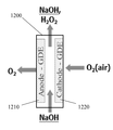
다른 실시 태양에서, 액체 전해질 및 기체 확산 전극을 포함하며; 기체 확산 전극은 기체 투과성 물질; 및 기체 확산 전극의 액체 전해질 면 상에 제공된 다공성 전도성 물질을 포함하며, 사용시에 기체 확산 전극은 기체 감극되는 것인 전기-합성 또는 연료 전지가 제공된다. 즉, 감극 기체가 기체 투과성 물질로 도입된다. 기체 확산 전극은 카운터 전극일 수 있다. 다른 예에서, 이 형태의 두 개의 기체 확산 전극들은 연료 전지에 제공될 수 있다. 선택적으로, 기체 확산 전극들 모두는 감극될 수 있다. 예를 들어 제 1 감극 기체가 제 1 기체 확산 전극에서 또는 제 1 기체 확산 전극으로 도입될 수 있으며, 및/또는 제 2 감극 기체 제 2 기체 확산 전극에서 또는 제 2 기체 확산 전극으로 도입될 수 있다.In another embodiment, it comprises a liquid electrolyte and a gas diffusion electrode; The gas diffusion electrode comprises a gas permeable material; And a porous conductive material provided on the liquid electrolyte side of the gas diffusion electrode, wherein in use the gas diffusion electrode is gas reduced. That is, the negative electrode is introduced as a gas permeable material. The gas diffusion electrode may be a counter electrode. In another example, two gas diffusion electrodes of this type may be provided in the fuel cell. Alternatively, all of the gas diffusion electrodes can be depolarized. For example, a first cathodic gas may be introduced at the first gas diffusion electrode or into the first gas diffusion electrode, and / or at the second cathodic gas second diffusion electrode or into the second gas diffusion electrode .
한 예에서, 다공성 전도성 물질(또는 물질들)은 기체 투과성 물질에 부착되거나 또는 인접하여 위치한다. 다른 예에서, 다공성 전도성 물질은 기체 투과성 물질 상에 코팅되거나 증착된다. 다른 예에서, 기체 투과성 물질(또는 물질들)은 다공성 전도성 물질 상에 코팅되거나 증착된다. 다른 예에서 기체 투과성 물질은 비전도성이다.In one example, the porous conductive material (or materials) is attached to or positioned adjacent to the gas permeable material. In another example, the porous conductive material is coated or deposited on a gas permeable material. In another example, the gas permeable material (or materials) is coated or deposited on the porous conductive material. In another example, the gas permeable material is nonconductive.
다른 실시 태양에서, 액체 전해질; 및 액체 전해질에 실질적으로 불투과성인 기체 투과성 물질; 및 기체 확산 전극의 액체 전해질 면 상에 제공된 다공성 전도성 물질을 포함하는 기체 확산 전극을 포함하는 전기화학 전지를 포함하며, 사용시에 기체 확산 전극이 기체 감극되는 전기-합성 또는 연료 전지가 제공된다.In another embodiment, a liquid electrolyte; And a gas permeable material that is substantially impermeable to the liquid electrolyte; And an electrochemical cell including a gas diffusion electrode comprising a porous conductive material provided on a liquid electrolyte side of a gas diffusion electrode, wherein an electrochemical or fuel cell is provided in which the gas diffusion electrode is gas reduced.
다른 실시 태양에서, 전기-합성 또는 연료 전지 또는 장치에 사용하기 위한 기체 감극 전극이 제공되며, 기체 감극 전극은 기체 확산 전극이며 기체 투과성 물질; 및 기체 감극 전극의 액체 전해질 면 상에 제공된 다공성 전도성 물질을 포함한다. 바람직하게, 기체 투과성 물질은 실질적으로 액체 전해질 불투과성이다. 바람직한 태양에서, 기체 투과성 물질은 비전도성이다. 다른 태양들에서, 다공성 전도성 물질은 기체 투과성 물질에 부착되거나, 고정되거나, 인접하여 위치되거나, 또는 어느 정도 떨어져서 근처에 위치될 수 있다. 다른 예에서, 다공성 전도성 물질은 기체 투과성 물질 상에 코팅되거나 증착된다. 다른 태양에서, 다공성 전도성 물질은 바람직하게 바인더 물질을 사용하여 기체 투과성 물질에 부착된다. 기체 투과성 전극은 또한 기체 투과성 복합 3D 전극으로 불려질 수 있다.In another embodiment, there is provided a gaseous cathodic electrode for use in an electro-composite or fuel cell or device, wherein the gaseous cathodic electrode is a gas diffusion electrode and is a gas permeable material; And a porous conductive material provided on the liquid electrolyte side of the gas decaying electrode. Preferably, the gas permeable material is substantially liquid electrolyte impermeable. In a preferred embodiment, the gas permeable material is nonconductive. In other aspects, the porous conductive material may be attached, fixed, adjacent to, or some distance away from the gas permeable material. In another example, the porous conductive material is coated or deposited on a gas permeable material. In another aspect, the porous conductive material is preferably attached to the gas permeable material using a binder material. The gas permeable electrode may also be referred to as a gas permeable composite 3D electrode.
다공성 전도성 물질은 부착됨으로써 기체 투과성 물질에 부착될 수 있거나 또는 기체 투과성 물질에 적층될 수 있다. 선택적으로, 다공성 전도성 물질은 기체 투과성 물질의 적어도 일부 상에 코팅되거나 또는 증착됨으로써 기체 투과성 물질에 제공될 수 있다. 선택적으로, 기체 투과성 물질은 다공성 전동성 물질의 적어도 일부 상에 코팅되거나 또는 증착됨으로써 기체 다공성 전도성 물질에 제공될 수 있다.The porous conductive material may be attached to the gas permeable material by attachment or may be laminated to the gas permeable material. Optionally, the porous conductive material may be provided on the gas permeable material by being coated or deposited on at least a portion of the gas permeable material. Optionally, the gas permeable material may be provided on the gas porous conductive material by being coated or deposited on at least a portion of the porous electrically conductive material.
설명적인 예로서, 본 발명자들은 상대적으로 균일하고 뚜렷한 기체 투과성 구조들을 가진 폴리머들과 같은 물질들을 예를 들어, 금속 메쉬들, 그리드들, 격자들, 옷감들 또는 웹들, 또는 다공 금속 시트들과 같은 다공성 전도성 물질들(본 발명에서는 다공성 또는 투과성 금속성 원소, 물질 또는 층으로도 언급됨)과 조합하는 것/적층하는 것이 대단히 높은 전기화학 및 전기촉매적 활성, 강함, 및/또는 단위 부피당 고효율 전기화학 영역과 같은 예상치 못한 신규한 특성들을 가진 복합 3D 전극들을 생산할 수 있다는 것을 발견하였다.As an illustrative example, the present inventors have discovered that materials such as polymers having relatively uniform and distinct gas permeable structures can be used as materials for the formation of, for example, metal meshes, grids, gratings, fabrics or webs, The combination / lamination of porous conductive materials (also referred to herein as porous or transmissive metallic elements, materials or layers) is a highly electrochemical and electrocatalytic activity, strong, and / or highly efficient electrochemical per unit volume Regions, such as < RTI ID = 0.0 > a < / RTI >
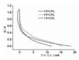
본 발명자들은 세심하게 보정된 제조 방법에 의해 계면 또는 경계 지역이 형성되는 경우 불균형적으로 증폭된 전기화학 특성들이 최대로 관찰된다는 것을 추가로 발견하였다. 전극이 종합적으로 1 mA/cm2 내지 500 mA/cm2 또는, 바람직하게, 1 mA/cm2 내지 200 mA/cm2, 또는 바람직하게 1 mA/cm2 내지 100 mA/cm2와 같은 상대적으로 낮은 전류 밀도들에서 작동하는 경우 향상된 전기화학 특성들이 또한 관찰되었다. 작동 조건들 하에서 뚜렷하고, 좁고, 안정적이며, 및/또는 강한 3-방향 고체-액체-기체 경계가 형성되고 유지되었기 때문에 증폭된 특성들이 관찰되었다.The present inventors have further found that disproportionately amplified electrochemical properties are maximally observed when an interface or boundary region is formed by a carefully calibrated manufacturing process. The electrodes are collectively referred to as 1 mA / cm 2 to 500 mA / cm 2 Or when operating at relatively low current densities, such as preferably 1 mA / cm 2 to 200 mA / cm 2 , or preferably 1 mA / cm 2 to 100 mA / cm 2 , . Amplified properties were observed because clear, narrow, stable, and / or strong three-way solid-liquid-gas interfaces under the operating conditions were formed and maintained.
따라서, 예를 들어, 본 발명자들은 다공성 전도성 물질이 메쉬, 그리드, 격자, 옷감, 웹 또는 다공 시트일 수 있거나 이들로 만들어질 수 있다는 것을 발견하였다. 물질, 예를 들어 폴리머 층이 기체 투과성(즉 이전에 기술한 바와 같이 폴리머 층이 하나 이상의 기체 투과성 물질들로 형성되거나 또는 하나 이상의 기체 투과성 물질들을 포함한다)이며 액체 전해질 불투과성이라면, 예를 들어 복합 3D 전극들에서 비전도성 폴리머 층 또는 층들을 제공하는 기체 투과성 물질은 다공성, 비-다공성일 수 있거나, 또는 다공성 층의 상부 상의 비-다공성 층의 샌드위치를 포함하는 다공성 및 비-다공성 물질의 조합으로 구성될 수 있다. 촉매성, 전도성, 및/또는 다른 물질들과 함께 제공될 수 있는 바인더 물질(들)이 다공성 전도성 물질 및/또는 기체 투과성 물질에 첨가되거나, 이들 상에 위치하거나, 포개어지거나 및/또는 포개어지고 이들 내로 또는 이들을 통할 수 있다. 바인더 물질(들)은 또한 전도성 금속층(즉 다공성 전도성 물질) 및 폴리머 층(즉 기체 투과성 물질) 사이에, 즉 경계 지역에 존재할 수 있어 전극들의 구조적인 무결성, 전기 및 구조적 무결성, 및/또는 강함을 향상시킨다. 바람직한 형태에서, 바인더 물질은 이의 주요 목적이 결합하는 것이며 따라서 그 안에 통상적인 3D 미립자 고정층 전극들에서 발견될 수 있는 3-방향 고체-액체-기체 경계가 형성되는 미립자 카본 블랙의 매트릭스를 제공하지 않는다는 사실을 특징으로 한다.Thus, for example, the inventors have discovered that the porous conductive material can be, or can be, a mesh, a grid, a grid, a cloth, a web, or a porous sheet. If the material, e. G., The polymer layer, is gas permeable (i. E., The polymer layer is formed of one or more gas permeable materials or includes one or more gas permeable materials as previously described) and liquid electrolyte impermeable, The gas permeable material providing the nonconductive polymer layer or layers in the composite 3D electrodes may be porous, non-porous, or may be a combination of porous and non-porous materials, including sandwiches of non-porous layers on top of the porous layer . The binder material (s) that may be provided with catalytic, conductive, and / or other materials may be added to, placed on, overlaid and / or overlaid on the porous conductive material and / or gas permeable material Or through them. The binder material (s) may also be present between the conductive metal layer (i.e., the porous conductive material) and the polymer layer (i.e., the gas permeable material), i.e., at the boundary region, to improve the structural integrity, electrical and structural integrity, and / . In a preferred form, the binder material is one whose main purpose is to combine and thus does not provide a matrix of particulate carbon black in which a three-way solid-liquid-gas interface can be found in conventional 3D particulate fixed bed electrodes It is characterized by fact.
더욱이, 본 실시태양들의 복합 3D 전극들이 기체-대-액체 및/또는 액체-대-기체 방법들에 대해 구성되는 경우, 이들은 사용시에 유익한 고체-액체-기체 경계들, 예를 들어 독특하게 뚜렷하고, 좁고, 안정적이며, 및/또는 강한 3-방향 고체-액체-기체 경계들을 나타내는 기체 확산 전극들(GDE)로서 역할할 수 있다. 이러한 경계들은 특히 다른 3D 전극들에 대하여 그리고 제조 비용 측면에서 예상치 못했던 증폭된 전기화학 성능을 초래할 것이다.Moreover, when the composite 3D electrodes of the embodiments are configured for gas-to-liquid and / or liquid-to-gas methods, they are advantageous solid-liquid-gas boundaries in use, for example uniquely distinct, narrow , Stable, and / or as gas diffusion electrodes (GDE) that exhibit strong three-way solid-liquid-gas boundaries. These boundaries will result in unexpected amplified electrochemical performance, especially for other 3D electrodes and in terms of manufacturing cost.
바람직하지만 이에 한정되지는 않게, 상기 종류 또는 형태의 GDE는 산소 또는 수소를 포함하지만 이에 제한되지 않는 기체들을 전극들을 감극하기 위한 목적으로 전기화학 전지들 및 장치들 내 전극들로 또는 이들 전극들을 통해 운송하기 위해 사용된다. 즉, 바람직하게 감극 기체는 전극을 기체 감극하기 위한 적어도 하나의 기체 확산 전극에 의해 수용된다.Desirably, but not exclusively, the GDE of this type or type may include, but is not limited to, oxygen or hydrogen, to and from electrodes in electrochemical cells and devices for the purpose of depolarizing electrodes. Used for transportation. That is, preferably, the negative electrode is accommodated by at least one gas diffusion electrode for gas-depressing the electrode.
바람직하지만 이에 한정되지는 않게, 감극 기체는 전극에서 일어나는 반쪽-반응을 에너지적으로 보다 유리한 반쪽-반응으로 변화시킨다.Preferably but not exclusively, the depolarizing gas changes the half-reaction occurring in the electrode into an energetically more favorable half-reaction.
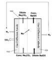
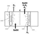
바람직하지만 이에 한정되지는 않게, 전기화학 전지는 (a) 과산화수소, (b) CO2로부터의 연료, (c) 오존, (d) 부식제(caustic)(염소가 없음), (e) 과망간산칼륨, (f) 염소산염, (g) 과염소산염, (h) 불소, (i) 브롬, (j) 과황산염, (k) 염소, (l) 부식제(일반), (m) 메탄으로부터의 CO2, 및 다른 것들의 전기화학적 제조에서 사용된다.Preferably, but not exclusively, the electrochemical cell comprises (a) hydrogen peroxide, (b) fuel from CO 2 , (c) ozone, (d) caustic (chlorine free), (e) potassium permanganate, (f) chlorite, (g) perchlorates, (h) fluorine, (i) bromine, (j) a persulfate, (k) chlorine, (l) caustic (normal), (m) CO from methane 2, and It is used in the electrochemical production of others.
선택적인 예들에서, 전기화학 전지는 특정 산업들에 특유한 전기화학 방법들을 수반한다. 예들은 다음을 포함한다:In alternative examples, electrochemical cells involve electrochemical methods that are specific to certain industries. Examples include:
(i) 전해 채취와 같은 전기야금 응용들; (i) Electro-metallurgical applications such as electrolytic harvesting;
(ii) (a) "흑액" 전기분해, (b) "톨유 회수" 및 (c) 염화물 제거 전기분해와 같은 펄프 및 종이 산업 응용들; 및(ii) pulp and paper industry applications such as (a) " black solution " electrolysis, (b) " tall oil recovery " and (c) chloride removal electrolysis; And
(iii) 알카라인 연료 전지들을 포함하지만 이에 제한되지 않는 수소-산소 연료 전지들과 같은 연료 전지 및 관련된 장치 응용들.(iii) Fuel cells and related device applications, such as hydrogen-oxygen fuel cells, including, but not limited to, alkaline fuel cells.
다른 실시 태양에서, 적어도 하나의 기체 확산 전극의 존재 및 작동은 다음을 포함하지만 이에 제한되지 않는 산업적으로 유익한 효과를 가진다:In another embodiment, the presence and operation of at least one gas diffusion electrode has an industrially advantageous effect, including but not limited to:
i. 통상적인 기체 확산 전극이 사용되었을 경우에 비하여 전기-합성 또는 전기-에너지 전지 또는 장치에 필요한 전체 에너지를 감소시킨다.i. Reduces the total energy required for an electro-composite or electro-energy cell or device as compared to when a conventional gas diffusion electrode is used.
ii. 통상적인 기체 확산 전극이 사용되었을 경우에 비하여 전기-합성 또는 전기-에너지 전지 또는 장치의 비용-효율성 및 경제성을 증가시킨다.ii. Increases the cost-effectiveness and economy of an electro-composite or electro-energy battery or device compared to when a conventional gas diffusion electrode is used.
iii. 통상적인 기체 확산 전극이 사용되었을 경우에 비하여 전기-합성 또는 전기-에너지 전지 또는 장치를 수반하는 안전성과 관련된 측면들을 증가시킨다.iii. Increases the safety-related aspects involving an electro-composite or electro-energy cell or device compared to when a conventional gas diffusion electrode is used.
iv. 통상적인 기체 확산 전극이 사용되었을 경우에 비하여 전기-합성 또는 전기-에너지 전지 또는 장치와 관련된 원하지 않는 물질들의 향상된 재활용 또는 제거를 가능하게 해준다.iv. Allows for improved recycling or removal of unwanted materials associated with electrochemical or electro-energy cells or devices compared to when conventional gas diffusion electrodes were used.
v. 높이가 1 미터로 제한되지 않는 더 큰 전기화학 전지들을 가능하게 해준다; 이는 차례로 보다 작은 전지의 풋프린트(footprint)를 가능하게 해주며, 따라서 연료 전지를 수용하기에 필요한 바닥 면적을 감소시킨다.v. Enabling larger electrochemical cells that are not limited to one meter in height; This in turn enables the footprint of a smaller cell and thus reduces the floor area required to accommodate the fuel cell.
vi. 일반적으로, 통상적인 기체 확산 전극이 사용되었을 경우에 비하여 전기-합성 또는 전기-에너지 전지 또는 장치의 실용성을 향상시킨다.vi. Generally, the practicality of an electrochemical or electro-energy battery or device is improved compared to when a conventional gas diffusion electrode is used.
바람직한 실시태양에서, 유익한 효과/들은 전극을 통해 또는 전극으로 감극 기체를 적용함으로써 성취된다.In a preferred embodiment, beneficial effects / are achieved by applying a depolarizing gas to or through the electrode.
다른 실시 태양에서, 유익한 효과/들은 예를 들어 거품 형성으로부터 발생하는 에너지-낭비 저항 및 저항 손실을 제거하는 것과 같은 다른 수단들에 의해 성취된다.In another embodiment, beneficial effects / are achieved by other means such as, for example, eliminating energy-dissipating and resistive losses resulting from foam formation.
다른 실시 태양에서, 유익한 효과/들은 기체 확산 전극을 통해 전해질 누출 없이 더 큰 또는 현저하게 더 큰 압력을 (기체에 비해) 전해질에 적용하는 것으로부터 나타난다. 이 형태의 차압(differential pressure)은 예를 들어, 전극에서 반쪽-반응의 에너지 효율을 본질적으로 향상시키는 효과 및 따라서 전체 과정의 에너지 효율을 가질 수 있다. 선택적으로, 다른 실시 태양에서, 유익한 효과/들은 액체 전해질 면에서 거품을 형성하기 위해 기체 확산 전극을 통과하는 기체 없이 더 큰 또는 현저하게 더 큰 압력을 (전해질에 비해) 기체에 적용하는 것으로부터 나타난다.In another embodiment, beneficial effects / appear from applying a greater or significantly greater pressure (relative to the gas) to the electrolyte without electrolyte leakage through the gas diffusion electrode. This type of differential pressure can, for example, have the effect of essentially improving the energy efficiency of the half-reaction at the electrode and thus the energy efficiency of the entire process. Alternatively, in another embodiment, beneficial effects / appear from applying a greater or significantly greater pressure (compared to the electrolyte) to the gas without the gas passing through the gas diffusion electrode to form a bubble in the liquid electrolyte surface .
바람직하게, 연료 전지는 기체 지역을 포함하며, 기체 확산 전극은 액체 전해질 및 기체 지역을 분리한다. 예를 들어, 서로 다른 기체들, 또는 동일한 기체에 대하여 한 개 초과의 기체 지역이 사용될 수 있다. 하나 이상의 기체 지역들은 일반적으로 기체 반응 물질들 또는 생성물들을 추출 또는 공급하기 위한 것이다.Preferably, the fuel cell comprises a gas region, and the gas diffusion electrode separates the liquid electrolyte and the gas region. For example, more than one gas region may be used for different gases, or the same gas. The one or more gas regions are generally for extracting or supplying gas reactants or products.
다른 실시 태양에서, 유익한 효과/들은 예를 들어 액체 전해질을 가열함으로써 전해질의 온도를 증가시키는 것 또는 현저하게 증가시키는 것으로부터 나타난다. 이는 기체 확산 전극을 통한 전해질 누출의 위험 없이 가능하거나 또는 감소된 위험을 가지고 가능하다. 여러 전기화학 방법들의 경우, 보다 높은 온도는 전극에서 반쪽-반응의 내재적 에너지 효율을 향상시키는 효과를 가질 것이며 따라서 전체 과정의 에너지 효율을 증가시킨다. 여러 전해질 전지들은 반응을 유도하기 위해 적용되어야만 하는 과량의 에너지가 열로 방출된다는 점에서 "자기-가열(self heating)"이다.In another embodiment, the beneficial effect / s results from increasing or significantly increasing the temperature of the electrolyte, for example by heating the liquid electrolyte. This is possible with or without the risk of electrolyte leakage through the gas diffusion electrode. For many electrochemical methods, higher temperatures will have the effect of enhancing the intrinsic energy efficiency of the half-reaction at the electrode, thus increasing the energy efficiency of the entire process. Many electrolyte cells are "self-heating" in that a large amount of energy, which must be applied to induce a reaction, is released into the heat.
다른 실시 태양에서, 유익한 효과/들은 예시적인 GDE의 사용을 활용하기 위하여 존재하는 전기화학 방법의 조건들 및 전지 배열/구조를 변경함으로써 성취된다. 예를 들어, 본 발명에서 개시된 예시적인 GDE가 애노드 및 캐소드로서 사용되는 경우, 클로르-알칼리 방법이 서로 다른 반응 물질을 사용하기 위해 변경될 수 있다; 즉, 예를 들어 소금물 대신 염산. 이러한 변경은 전극들 사이의 비싸고 효율을 저해하는 소듐 교환막에 대한 필요를 제거할 수 있다. 더욱이, 이후 캐소드가 산소로 감극되는 경우, 변경된 전지는 오직 순수한 염소만을 생성하며 이는 특정 지점들에서 특히 사용자들에 의해 필요로 되지 않는 원하지 않는 수소 부산물을 생성하지 않는다(통상적인 클로르-알칼리 방법에서 생성되는 부식제 부산물 NaOH도 생성하지 않는다). 이러한 형태의 전지는 추가적으로 염소의 소규모 현장(on-site) 생성을 받아들일 수 있으며, 이는 염소 기체의 독성 특성을 고려하면, 중심 플랜트에서 염소를 생성하고 실린더들 또는 다른 컨테이너들의 염소를 소규모 사용자들에게 운반하는 것보다 더 안전하다. 더욱이, 이러한 전지는 고효율 및 낮은 비용, 가용성, 본 발명에서 참고로서 포함되는 본 출원인의 2014년 7월 30일에 함께 출원된 PCT 출원 "Modular Electrochemical Cells"에서 기술된 형태의 나선형으로 감긴(spiral-wound) 구조에서 최적으로 구성될 수 있다. 이러한 구조는 다른 이용가능한 구조들보다 실질적으로 더 실용적이며 효율적일 수 있다.In another embodiment, beneficial effects / are achieved by altering the conditions and cell arrangement / structure of the electrochemical method present to utilize the use of an exemplary GDE. For example, when the exemplary GDEs disclosed herein are used as the anode and the cathode, the chlor-alkali process can be modified to use different reactants; Namely, for example, hydrochloric acid instead of brine. This modification can eliminate the need for expensive and inefficient sodium exchange membranes between the electrodes. Moreover, if the cathode is subsequently depressed with oxygen, the modified cell produces only pure chlorine, which does not produce undesired hydrogen by-products, which are not specifically needed by users at particular points (in a conventional chlor- But does not produce the caustic by-product NaOH produced). This type of cell can additionally accept small on-site production of chlorine, which, considering the toxic nature of the chlorine gas, can produce chlorine in the central plant and convert chlorine in cylinders or other containers into small- It is safer than carrying it to. Moreover, such cells are highly efficient and cost-effective, and are available in a variety of configurations including spiral-wound, as described in PCT application filed "Modular Electrochemical Cells " filed on July 30, wound structure. Such a structure may be substantially more practical and efficient than other available structures.
다른 실시 태양에서, 유익한 효과/들은 예시적 실시태양들에 따른 GDE가 존재하지만 지금까지 실행 불가능한 화학적 방법을 실용적으로 달성할 수 있게 만들 수 있다는 사실에 의해 성취된다. 예를 들어, 부식성 흐름에서 과산화수소를 제조하기 위한 다우-휴론 방법은 대체로 실행 불가능한 것으로 증명되었으며, 이는, 부분적으로는, 캐소드를 감극하기 위해 사용되는 트리클-베드(trickle-bed) 반응기 때문이다. 예시적 실시태양들에 따른 GDE가 이러한 반응기 대신 사용될 수 있으며 따라서 잠재적으로 방법을 보다 실행 가능하게 만들어준다. 추가적으로, 이 방법의 소규모, 모듈화된 버전이 만들어질 수 있으며, 이는 지금까지 고려되지 못하였던 또는 실용적이지 않은 것으로 증명되었던 새로운 응용들을 가능하게 할 수 있다.In another embodiment, beneficial effects / are achieved by the fact that GDE according to the exemplary embodiments is present, but can make up to now impractical chemical methods practically achievable. For example, the Dow-Huron method for producing hydrogen peroxide in a corrosive flow has proven to be practically impractical, in part because of the trickle-bed reactor used to negate the cathode. GDE according to exemplary embodiments can be used instead of these reactors and thus potentially makes the process more feasible. Additionally, a small, modular version of this method can be created, which can enable new applications that have not been considered previously or have proven to be impractical.
다른 실시 태양에서, 유익한 효과/들은 예시적 실시태양들에 따른 GDE가 전지들 또는 장치들에서 완전히 새로운 화학적 방법들을 수행하는 것을 가능하고 실용적이게 해준다는 사실에 의해 성취된다. 예시적 실시태양들에 따른 GDE를 사용하면 예를 들어, 이산화탄소로부터의 연료의 형성, 또는 SOx 및 NOx 오염의 개선에 대하여 지금까지 고려되지 않았던 방법들이 가능하고 실용적이다. 지금까지 알려지지 않았던 직접 메탄 연료 전지 또한 예시적 실시태양 GDE를 사용하여 구성되었다.In another embodiment, beneficial effects / are achieved by the fact that GDE according to exemplary embodiments makes it possible and practical to perform completely new chemical methods in batteries or devices. Exemplary embodiments The GDE according to the aspect, for example, the formation of the fuel from the carbon dioxide, or SO x And Methods not previously considered for the improvement of NO x contamination are possible and practical. Until now, direct methane fuel cells have also been constructed using the exemplary embodiment GDE.
다른 예시적 실시태양에서, 하나 이상의 GDE가 감극 기체를 감극 전극뿐만 아니라 충분한 양의 기체를 전해질로 보내서 반응기 내에서 일어날 거품의 형성을 유발하여 전해질 내의 혼합을 유발하며, 따라서 물질 전달을 증가시키고 농도 분극화 효과들을 감소시키도록 주입 또는 도입하기 위해 사용된다. 선택적으로, 하나 이상의 GDE가 불활성 기체 또는 불활성 기체 및 감극 기체의 일부 조합을 주입하기 위해 사용된다. 이 실시태양에서, GDE는 미세한 거품 확산기(diffuser)처럼 작용하며, 두 개의 기능들을 수행할 수 있다: 기체를 연료 전지에 첨가하는 기능 및 또한 혼합을 제공하는 기능. 따라서, 감극 기체 및/또는 불활성 기체는 적어도 하나의 전극을 통해 액체 전해질 내로 보내질 수 있어서 액체 전해질에서의 거품 형성 및/또는 혼합을 유발한다.In another exemplary embodiment, one or more GDEs send a negative electrode as well as a negative electrode to the electrolyte to cause the formation of bubbles to occur in the reactor, thereby causing mixing in the electrolyte, thus increasing mass transfer and increasing concentration Is used to inject or introduce to reduce polarization effects. Optionally, one or more GDEs are used to inject an inert gas or some combination of inert gas and depolarizing gas. In this embodiment, the GDE acts like a fine bubble diffuser and can perform two functions: the ability to add gas to the fuel cell and also the ability to provide mixing. Thus, the depolarizing gas and / or the inert gas can be sent into the liquid electrolyte through at least one electrode to cause foaming and / or mixing in the liquid electrolyte.
바람직하지만 이에 한정되지는 않게, 다공성 전도성 물질은 기체 투과성 물질에 물리적으로(예를 들어 기계적으로) 또는 화학적으로 결합함으로써 기체 투과성 물질(예를 들어 폴리머 층)에 부착된다. 이는 바람직하지만 이에 한정되지는 않게, 바인더 물질 또는 다공성 전도성 물질 및 기체 투과성 물질을 함께 결합하는 역할을 하는 물질들의 존재에 의해 성취된다. 바인더 물질은 모든 곳, 실질적으로 모든 곳 또는 다공성 전도성 물질 및 기체 투과성 물질의 계면 사이 또는 계면에서 거의 모든 곳에 존재할 수 있다. 선택적으로, 바인더 물질은 다공성 전도성 물질 및 기체 투과성 물질 사이의 작은 선택 지점들에서 존재할 수 있다. 바인더 물질 또는 물질들은 패턴으로 추가로 도포될 수 있어서 다공성 전도성 물질을 기체 투과성 물질에 단단하게 부착시킨다. 바인더 물질은 기체 투과성 물질을 형성하는 물질, 예를 들어 폴리머 층을 형성하는 폴리머 물질을 상당히 또는 전체적으로 포함할 수 있다. 선택적으로, 바인더 물질은 혼합물일 수 있으며 또한 전기 컨덕터 또는 촉매인 것과 같은 바인더 혼합물에 하나 이상의 다른 원하는 특성들을 동시에 부여할 수 있는 하나 이상의 관련되지 않은 물질들을 포함한다.Preferably, but not exclusively, the porous conductive material is attached to a gas permeable material (e.g., a polymer layer) by physically (e.g., mechanically) or chemically bonding to the gas permeable material. This is accomplished by the presence of materials that serve to bind the binder material or the porous conductive material and the gas permeable material together, though it is preferable, but not limited thereto. The binder material may be present anywhere, practically everywhere, or almost anywhere in the interface between the porous conductive material and the gas permeable material or at the interface. Optionally, the binder material may be present at small selection points between the porous conductive material and the gas permeable material. The binder material or materials may be further applied in a pattern so that the porous conductive material is firmly attached to the gas permeable material. The binder material may include a material that forms a gas permeable material, such as a polymeric material that forms a polymer layer, for example, quite or wholly. Optionally, the binder material may be a mixture and may include one or more unrelated materials capable of simultaneously imparting one or more other desired properties to a binder mixture such as an electrical conductor or catalyst.
추가적으로, 전극 또는 기체 투과성 물질(예를 들어 폴리머 층 또는 막)은 조밀한 박막, 즉 GDE를 통한 상업적으로 유용한 속도의 기체 운송을 가능하게 하기 위해 충분한 기체 투과성을 가지도록 선택되는 장벽층, 물질 또는 필름을 포함할 수 있거나 이에 부착될 수 있거나 또는 이와 결부될 수 있다. 장벽층은 완전히 비-다공성, 나노-다공성일 수 있으며, 또는 다공성 물질들 및 비-다공성 물질들의 매트릭스를 포함할 수 있다. 장벽층은 또한 전극 또는 GDE를 통한 전해질의 '플러딩'에 대한 추가적인 보호를 제공할 수 있다. 선택적으로, 장벽층은 바람직하지 않은 기체 또는 기체들의 양을 한정하기 위해, 예를 들어, 수증기가 기체 투과성 물질, 다공성 전도성 물질 또는 전극을 통해 투과하는 것을 한정하기 위해 선택될 수 있다. 예를 들어, 높은 산소 또는 수소 운송을 가지나 매우 낮은 수증기 운송을 가지는 적절한 물질들이 선택될 수 있다. 이러한 장벽층, 물질 또는 필름의 증착을 촉진하기 위하여, 매우 균일하고 극도로 평평한 표면을 가지는 '중간'층이 먼저 놓일 수 있다. 이후 앞서 언급한 장벽층, 물질 또는 필름이 '중간'층 상에 증착될 수 있다. 중간 막 층은 바람직하지만 이에 제한되지 않게, 작고 약 5 nm 내지 약 50 nm(하지만 주로 대략 약 10 nm 정도) 범위인 공극들을 가지는 다공성이다. 일반적인 중간층 화학물질들은 폴리설폰 및 폴리에터설폰일 수 있다.In addition, an electrode or a gas permeable material (e.g., a polymer layer or membrane) may be used as a barrier layer, material, or material that is selected to have sufficient gas permeability to enable dense thin films, i.e., May include, be attached to, or be associated with, a film. The barrier layer may be completely non-porous, nano-porous, or may comprise a matrix of porous and non-porous materials. The barrier layer may also provide additional protection against electrolyte ' flooding ' through the electrode or GDE. Alternatively, the barrier layer can be selected to define the amount of undesirable gases or gases, for example, to limit the permeation of water vapor through the gas permeable material, the porous conductive material or the electrode. For example, suitable materials with high oxygen or hydrogen transport but very low water vapor transport can be selected. In order to facilitate the deposition of such barrier layers, materials or films, an 'intermediate' layer with a very uniform and extremely flat surface can be placed first. The aforementioned barrier layer, material or film may then be deposited on the " intermediate " layer. The intermediate membrane layer is porous, having a pore size that is small, but is in the range of about 5 nm to about 50 nm (but mainly about 10 nm), although it is preferred, but not limited thereto. Common interlayer chemicals can be polysulfones and polyether sulfones.
다른 예시적인 형태에서, 다공성 전도성 물질(전도성 층)은 GDE의 외부 표면의 일부이며 상대적으로 기체 투과성 물질보다 덜 소수성이다. 다른 예시적인 형태에서, 벌크 GDE는 기체 통기성이며 액체 불투과성이다.In another exemplary embodiment, the porous conductive material (conductive layer) is part of the outer surface of the GDE and is relatively less hydrophobic than the gas permeable material. In another exemplary embodiment, the bulk GDE is gas permeable and liquid impermeable.
다양한 추가적인 예들에서: 다공성 전도성 물질 또는 층이 기체 투과성 물질에 부착하여, 기체 투과성 물질에 인접하게 위치하여, 기체 투과성 물질에 위치하여 또는 기체 투과성 물질에 적층되어, 또는 적어도 부분적으로 기체 투과성 물질 내에 제공된다; 다공성 전도성 물질 또는 층이 기체 투과성 물질과 결부된다; 다공성 전도성 물질 또는 층이 기체 투과성 물질 상에 및/또는 기체 투과성 물질 내에 위치한다; 및/또는, 기체 투과성 물질이 다공성 전도성 물질 또는 층 상에 및/또는 다공성 전도성 물질 또는 층 내에 위치한다. 다른 예들에서, 기체 투과성 물질은 기체 투과성 막 또는 구조, 기체 투과성 폴리머 막 또는 구조, 기체 투과성 다공성 폴리머 막 또는 구조, 또는 기체 투과성 다공성 막 또는 구조이다.In various additional examples, a porous conductive material or layer may be attached to a gas permeable material, positioned adjacent to the gas permeable material, located in a gas permeable material, laminated to a gas permeable material, or at least partially provided within a gas permeable material do; The porous conductive material or layer is associated with a gas permeable material; The porous conductive material or layer is located on the gas permeable material and / or in the gas permeable material; And / or the gas permeable material is located on the porous conductive material or layer and / or in the porous conductive material or layer. In other examples, the gas permeable material is a gas permeable membrane or structure, a gas permeable polymer membrane or structure, a gas permeable porous polymer membrane or structure, or a gas permeable porous membrane or structure.
선택적이지만, 바람직하게는, GDE는 가요성이다. 선택적으로, 다공성 전도성 물질 또는 층은 적어도 부분적으로 또는 전부 가요성인 물질 및/또는 가요성인 형태로 만들어진다. 선택적으로, 기체 투과성 물질은 적어도 부분적으로 또는 전부 가요성인 물질 및/또는 가요성인 형태로 만들어진다. 선택적으로, 기체 투과성 물질은 적어도 부분적으로 또는 전부 폴리머 또는 폴리머들의 조합, 예를 들어, PTFE, "팽창된 PTFE"(ePTFE), 폴리에틸렌 또는 폴리프로필렌으로 만들어진다. 폴리머 그 자체는 기체 투과성일 수 있거나 기체 투과성이 아닐 수 있다. 예를 들어, 폴리머 그 자체는 기체 투과성이 아니지만 폴리머로 만들어진 구조 또는 막은 기체 투과성이다.Optionally, but preferably, the GDE is flexible. Optionally, the porous conductive material or layer is made at least partially or completely flexible and / or in a flexible form. Optionally, the gas permeable material is at least partially or wholly flexible and / or is made in a flexible form. Optionally, the gas permeable material is at least partially or entirely made of a polymer or a combination of polymers such as PTFE, "expanded PTFE" (ePTFE), polyethylene or polypropylene. The polymer itself may be gas-permeable or non-gas-permeable. For example, the polymer itself is not gas permeable, but the structure or membrane made of polymer is gas permeable.
예시적 태양들에서 전극들, 하나 이상의 전극들을 사용하는 장치들 또는 전지들, 및/또는 전극들을 제조하는 방법들이 제공되며, 전극들은 기체-대-액체 및/또는 액체-대-기체 변환들을 제공하는데 사용된다. 비제한적인 예시적 적용들에서 전극들은 (i) 대기-기반 산소를 보다 깨끗한 또는 깨끗한 산소로 변환; (ii) 과산화수소를 제조; (iii) 연료 전지들; (iv) 실온에서 작동하는 직접 메탄 연료 전지들에 사용될 수 있다. 다른 예들에서, 전극들은 전기화학 장치들 또는 전지들의 다른 형태들에서 사용된다.Methods are provided for manufacturing electrodes, electrodes, and / or electrodes using one or more electrodes in exemplary embodiments, wherein the electrodes provide gas-to-liquid and / or liquid-to-gas conversions . In non-limiting exemplary applications, the electrodes may be configured to (i) convert air-based oxygen to cleaner or cleaner oxygen; (ii) preparing hydrogen peroxide; (iii) fuel cells; (iv) direct methane fuel cells operating at room temperature. In other instances, the electrodes are used in electrochemical devices or other forms of batteries.
본 발명의 내용 중에 포함되어 있다.Are included in the scope of the present invention.
예시적 실시태양들이 첨부된 도면들을 참고하여 단지 비-제한적인 실시예들로 기술될 것이다. 첨부된 도면들과 관련하여 설명되는 적어도 하나의 바람직하지만 비-제한적인 실시태양의 단지 실시예로서 주어진 다음 설명으로부터 다양한 예시적 실시태양들이 명확해질 것이다.
도 1(종래기술)은 통상적인 기체 확산 전극을 개략적인 형태로 도시한다. 도면의 하부는 통상적인 기체 확산 전극의 단면의 확대도이다.
도 2는 본 실시태양들(치수에 비례하지 않음)에 따른 예시적인 3D 전극, 또는 기체 확산 전극을 개략적인 형태로 도시한다. 도면의 하부는 기체 확산 전극의 단면의 확대도이다.
도 3은 예시적인 GDE(치수에 비례하지 않음)의 개략적인 단면도를 도시한다.
도 4는 두 개의 외부 표면들이 모두 전도성(치수에 비례하지 않음)인 예시적인 GDE의 개략적인 측면도를 도시한다.
도 5(종래기술)는 통상적인 전기화학 전지에서의 클로르-알칼리 방법의 개략적인 도면을 도시한다.
도 6은 전기-합성(즉 전기화학) 전지의 각 전극에서 GDE를 사용하기 위해 개작한 클로르-알칼리 방법의 개략적인 도면을 도시한다.
도 7은 전기-합성(즉 전기화학) 전지에서 캐소드에 도입된 감극 산소를 가진 각 전극에서 GDE를 사용하기 위해 개작한 클로르-알칼리 방법의 개략적인 도면을 도시한다.
도 8은 전기-합성(즉 전기화학) 전지에서 캐소드에 도입된 감극 산소, 및 시약으로서 염산을 가진 각 전극에서 GDE를 사용하기 위해 개작한 클로르-알칼리 방법의 개략적인 도면을 도시한다.
도 9는 전기-합성(즉 전기화학) 전지에서 오직 부식제를 만들기 위해 개작한 클로르-알칼리 방법의 개략적인 도면을 도시한다.
도 10(종래기술)은 통상적인 전기화학 전지에서 다우-휴론 방법의 개략적인 도면을 도시한다.
도 11은 전기-합성(즉 전기화학) 전지에서 예시적인 GDE를 사용하기 위해 변형된 다우-휴론 방법의 개략적인 도면을 도시한다.
도 12은 전기-합성(즉 전기화학) 전지에서 예시적인 GDE를 사용하기 위해 변형된 다우-휴론 방법의 개략적인 도면을 도시한다.
도 13은 예시적인 전지(치수에 비례하지 않음)의 개략도를 도시한다.
도 14는 도시된 것과 같은 전압의 규칙적인 스위칭 온 및 오프 및 전압의 증가를 가진 시간에 대해 실시예 8에서 얻어진 전류를 도시한다.
도 15는 실시예 9에 기술된 수소-산소 연료 전지에 의해 생성된 분극화 커브를 도시한다.
도 16은 실온에서 작동하는 직접 메탄 연료 전지의 개략적인 도면을 도시한다.
도 17은 메탄 및 산소로 20분간 세척한 이후 직접 메탄 연료 전지의 분극화 커브들을 도시한다.
도 18은 오염 개선에 사용될 수 있는 예시적인 연료 전지의 개략적인 도면을 도시한다.
도 19 어떻게 하나 이상의 가요성 3D 전극들이 감아지거나 나선형으로 감길 수 있는지의 예시를 개략적으로 도시한다.
도 20은 예를 들어, 애노드-캐소드 쌍으로서 적층되거나 층을 이룬 이후 어떻게 가요성 3D 전극들이 예시적인 나선형으로 감긴 전지 또는 장치로 형성될 수 있는지의 예시를 개략적으로 도시한다.Exemplary embodiments will now be described, by way of non-limiting examples only, with reference to the accompanying drawings. Various illustrative embodiments will be apparent from the following description, given as merely an example of at least one preferred but non-limiting embodiment described in connection with the accompanying drawings.
1 (Prior Art) shows a conventional gas diffusion electrode in a schematic form. The lower part of the drawing is an enlarged view of a cross section of a conventional gas diffusion electrode.
Figure 2 schematically illustrates an exemplary 3D electrode, or gas diffusion electrode, according to these embodiments (not to scale). The lower part of the drawing is an enlarged view of a cross section of the gas diffusion electrode.
Figure 3 shows a schematic cross-sectional view of an exemplary GDE (not to scale).
Figure 4 shows a schematic side view of an exemplary GDE in which both exterior surfaces are conductive (not to scale).
Figure 5 (prior art) shows a schematic view of a chlor-alkali process in a conventional electrochemical cell.
Figure 6 shows a schematic view of a modified Chlor-Alkali process for using GDE at each electrode of an electro-composite (i.e., electrochemical) cell.
Figure 7 shows a schematic view of a modified chlor-alkali process for use of GDE in each electrode with cathodic oxygen introduced into the cathode in an electro-composite (i.e., electrochemical) cell.
Figure 8 shows a schematic view of a chlor-alkali process adapted for use of GDE in each electrode with cathodic oxygen introduced into the cathode in an electro-composite (i.e., electrochemical) cell and with hydrochloric acid as reagent.
Figure 9 shows a schematic view of a chlor-alkali process adapted to make only caustic in an electro-composite (i.e., electrochemical) cell.
Figure 10 (prior art) shows a schematic diagram of the Dow-Huron method in a conventional electrochemical cell.
Figure 11 shows a schematic diagram of a modified Dow-Huron method for using an exemplary GDE in an electro-composite (i.e., electrochemical) cell.
Figure 12 shows a schematic diagram of a modified Dow-Huron method for using an exemplary GDE in an electro-composite (i.e., electrochemical) cell.
Figure 13 shows a schematic view of an exemplary battery (not to scale).
Figure 14 shows the current obtained in embodiment 8 for a time with regular switching on and off and voltage increase of the voltage as shown.
15 shows the polarization curve produced by the hydrogen-oxygen fuel cell described in Example 9. Fig.
Figure 16 shows a schematic view of a direct methane fuel cell operating at room temperature.
Figure 17 shows the polarization curves of a direct methane fuel cell after 20 minutes of washing with methane and oxygen.
Figure 18 shows a schematic view of an exemplary fuel cell that can be used to improve contamination.
Figure 19 schematically illustrates an example of how one or more flexible 3D electrodes can be coiled or coiled.
20 schematically illustrates an example of how flexible 3D electrodes may be formed into an exemplary spirally wound cell or device after being laminated or layered, for example as an anode-cathode pair.
단지 예시하기 위해 제시된 하기 모드, 특징, 또는 양태는 청구된 발명의 바람직한 실시태양 또는 실시태양을 보다 정확하게 이해를 제공하기 위하여 상술된다. The following modes, features, or aspects, which are presented for illustrative purposes only, are set forth in order to provide a more thorough understanding of the preferred embodiments or embodiments of the claimed invention.
3D 전극 및 기체 확산 전극(3D electrode and gas diffusion electrode ( GDEGDE )을 제조하는 새로운 접근법A new approach to manufacturing
도 2는 본 실시태양에서 사용될 수 있는 예시적인 3D 전극 또는 GDE(115)의 일반적인 구조체를 개략적인 형태로 예시한다. 본 실시태양의 3D 전극 또는 GDE(115)는, 두 개의 구분되는 지역으로 소수성 공극 구조체 및 전도성의 특징들, 바람직하게 촉매 활성을 분리한다는 점에서 통상적인 3D 미립자 고정층 전극 또는 GDE(110)와 상이하고, 이들 특징은 각각 개선되고 통상적인 3D 미립자 고정층 전극 또는 GDE에서 가능한 것보다 더욱 완전하게 제어될 수 있다. 일부 실시태양에서, 둘 이상의 구분된 지역이 가능할 수 있다. 따라서, 3D 전극 또는 GDE(115)의 예시적인 실시태양은 액체-및-기체-다공성 도전체(130)(즉, 다공성 전도성 물질)로 구성될 수 있고, 이는 액체 전해질 불투과성인, 예를 들어, 강한 소수성인 비전도성 기체 투과성 물질(120)에 결합되거나, 부착되거나, 인접하거나 또는 이웃하게 위치된 촉매가 바람직하게 제공될 수 있다. 기체 투과성 물질(120) 및 도전체(130)(즉, 다공성 전도성 물질)는 실질적으로 구분되거나, 구별되거나 또는 분리됨으로써 제 1 지역(135)(전도성 지역) 및 구분되는 제 2 지역(125)(기체 투과성 지역)을 각각 제공한다. 기체 투과성 물질(120) 및 도전체(130)는 바람직하게 이웃하여, 인접하여, 접촉하여 또는 서로 경계를 이루게 위치되어, 경계 지역 또는 계면(140)에서 지역의 주변부의 접촉 또는 중첩이 있을 수 있다. 비전도성 소수성 기체 투과성 물질(120)은 통상적인 3D 전극 또는 GDE에서 달성될 수 있는 것보다 더 양호하게 정의되고, 더 균일하고 잠재적으로 더 작은 평균 크기인 공극을 나타낼 수 있다. 액체-및-기체-다공성 도전체(130)는 유사하게 통상적인 3D 전극 또는 GDE보다 더 전도성일 수 있다. 또한 액체-및-기체-다공성 도전체(즉, 다공성 전도성 물질)(130)의 낮은 소수성은, 통상적으로, 이것이 정상 작동 조건하에서 액체 전해질로 완전하게 또는 실질적으로 완전하게 채워짐으로써 촉매작용을 최대로 촉진할 것이다. 반대로, 비전도성 기체 투과성 물질(120)의 액체 불투과성 또는 높은 소수성은 전형적으로 이것이 대기압에서 액체 전해질이 완전하게 비거나 또는 실질적으로 비어서 GDE(115) 내로 및 밖으로 기체 이송을 최대로 촉진할 것이다. Figure 2 illustrates in schematic form the general structure of an exemplary 3D electrode or
따라서, 기체 투과성 3D 전극(115)은 비전도성인 기체 투과성 물질(120), 및 기체 투과성 물질(120)에 부착된 다공성 전도성 물질(130)을 제공한다. 작동에서, 기체 투과성 물질(120)은 전지의 기체 면을 대면하고, 다공성 전도성 물질(130)은 전지의 액체 전해질 면을 대면한다. 사용에서, 3상 고체-액체-기체 경계는 다공성 전도성 물질(130)을 대면하는 기체 투과성 물질(120)의 표면(122)에 또는 근처에 형성될 수 있다. Thus, the gas
다공성 전도성 물질(130)은, 소수성일 수 있는, 비전도성 기체 투과성 물질(120)에 결합되거나, 접촉하거나, 이웃하여 위치하거나 부착되거나 인접하여, 다공성 전도성 물질(130) 및 비전도성 기체 투과성 물질(120) 사이의 계면(140)(또는 경계 지역)을 형성하거나 제공한다. 바람직하게, 이는 구분되거나, 구별되거나 분리된 두 개의 지역(다공성 전도성 물질(130)을 포함하는 제 1 지역(135), 및 비전도성 기체 투과성 물질(120)을 포함하는 제 2 지역(125))을 제공한다. 바람직하게, 제 1 지역(135) 및 제 2 지역(125)은 이웃하여, 인접하게, 접촉하게 또는 서로 경계를 이루게 위치되어, 제 1 지역(135) 및 제 2 지역(125)에 대한 계면(140)(또는 경계 지역)이 존재한다. 따라서, 바람직한 실시태양의 작동에서, 3상 고체-액체-기체 경계는 제 1 지역(135)(즉, 다공성 전도성 물질(130), 이는 촉매를 포함할 수 있다) 및 제 2 지역(125)(즉, 비전도성 기체 투과성 물질(120)) 사이의 계면(140)에 또는 근처에(즉, 경계 지역에 또는 근처에) 있을 수 있는 다공성 전도성 물질(130)을 대면하는 기체 투과성 물질(120)의 표면(122)에 또는 근처에 형성된다. 한 예에서, 고체-액체-기체 경계는, 세포 또는 반응기에서 전극의 사용 동안 형성되는데, 전극(115)의 폭 또는 두께에 대하여 실질적으로 2차원인 거시적 폭을 가진다. 또 다른 예에서, 고체-액체-기체 경계는 기체 투과성 물질(120) 및 다공성 전도성 물질(130)의 계면(140)에서 형성된다.The porous
이러한 3D 전극 또는 GDE(115)가 액체 전해질에 의해 전도성 면에 및 기체 물질에 의해 비전도성 면에 접촉될 때, 상기 물리적 특징들은 표면(122)(또는 두 개의 지역 사이의 계면(140))에 또는 근처에 3상 고체-액체-기체 경계의 형성을 야기한다. 3상 고체-액체-기체 경계는 통상적인 3D 전극 또는 GDE에 형성되는 것과 사뭇 다르다. 경계는 통상적인 3D 전극 또는 GDE에 달성될 수 있는 것보다 훨씬 더 양호하게 정의되고, 더 좁고, 더 안정하고 및/또는 더 단단하다는 점에서 상이하다. 예를 들어, 표면(122)에 또는 근처에, 또는 다르게는 계면(140)에 또는 근처에 형성된 3상 고체-액체-기체 경계는 전극(115)의 폭에 대한 2차원 또는 실질적으로 2차원인 거시적 폭을 가진다. When such a 3D electrode or
이들 특징들은, 본 발명자들이 조심스럽게 보정된 방식으로 제조되는 경우, GDE(115)와 같은 예시적인 실시태양인 3D 전극 또는 GDE는, 기체 투과성 물질(120) 및 도전체(130) 사이에 계면(140)에서 향상된 또는 최적 기체 이송을 촉진하는 향상된 또는 최적 소수성 공극 구조체를 강화된 또는 최적으로 전도성이고 증가된 또는 최대화된 촉매 구조체와 결합할 수 있다는 것을 발견하였기 때문에 중요하다. 사실상, GDE(115)와 같은 예시적인 실시태양인 3D 전극 또는 GDE에서 3상 고체-액체-기체 경계에서, 전극의 결정적인 특징들은 각각 이상적으로 또는 적어도 다른 가능한 것보다 이상에 더 가깝게 제조될 수 있다. These features, when fabricated in a carefully calibrated manner by the present inventors, are 3D electrodes or GDE, which is an exemplary embodiment, such as
이 최적화의 효과는 주목할만하고 예측할 수 없이 중요할 수 있다. 비록 더 좁고, 거시적 2D 기하학인 것으로 나타난 것으로 한정되지만, GDE(115)와 같은 예시적인 실시태양인 3D 전극 또는 GDE에서 3상 고체-액체-기체 경계의 전기화학적 용량은 실질적으로 개선되고, 실상 GDE(110)와 같은 통상적인 3D 전극 또는 GDE의 그것을 훨씬 능가할 수 있다. The effect of this optimization can be remarkable and unpredictable. Although the electrochemical capacities of the three-phase solid-liquid-gas interface in 3D electrodes or GDE, which are exemplary embodiments such as
이는 당 분야에 현재 사용되는 통상적인 3D 전극 또는 GDE의 제조가 단일 물질 내에서 동시에 중요한 물리적 특징들 모두를 생성하는 것으로 예측되기 때문이다. 이 접근법은 3D 전극 또는 GDE의 주요 특성들(즉: 공극 구조체, 소수성, 기체 이송, 액체 이송, 전도성 및 촉매 활성)이 전형적으로 상호 의존적이고 따라서 단일 물질 내에 준비되며 동시에 최적화될 여지가 없다는 사실을 실질적으로 무시한다. 예시적인 실시태양인 3D 전극 또는 GDE(115)는 이 제한점을 고려하고, 주요 특성들을 별도로 최적화함으로써 기체 투과성 층(120) 및 전도성 층(130) 사이에 계면(140)에서 전체적인 특성을 보다 더 최적으로 달성한다. This is because the production of conventional 3D electrodes or GDEs currently used in the art is expected to produce all of the important physical features simultaneously in a single material. This approach is based on the fact that the main characteristics of 3D electrodes or GDEs (ie: pore structure, hydrophobicity, gas transfer, liquid transfer, conductivity and catalytic activity) are typically interdependent and thus can not be optimized simultaneously in a single material Substantially ignore. The exemplary embodiment 3D electrode or
본 발명자들은 사실 현미경 수준에서 3상 고체-액체-기체 경계가 예측할 수 없이 큰 전체 표면적을 가진 왜곡된 3D 구조체를 포함할 수 있다는 것을 추가적으로 발견하였다. 이는 특히 전도성 지역(135)이 기체 투과성 지역(125)과 어느 정도 중첩되는 경우이다. The inventors have further discovered that, at the microscopic level, the three-phase solid-liquid-gas interface can comprise a distorted 3D structure with an unpredictably large overall surface area. This is particularly the case where the
이들 매우 근본적인 향상들은 GDE(115)와 같은 예시적인 실시태양인 3D 전극 또는 GDE에 다양한 예측하지 못한 새로운 전기화학적 및 물리적 능력을 부여할 수 있다. 이들은: These very fundamental improvements can impart a variety of unpredictable new electrochemical and physical capabilities to 3D electrodes or GDE, which is an exemplary embodiment such as
1. 통상적인 3D 전극 또는 GDE에서 달성될 수 있는 것보다 훨씬 더 높은 습윤 압력 및 기포점. "습윤 압력"은, 액체 전해질이 관통하고 전극을 플러딩하는, 전극의 기체 면에 대한 3D 전극 또는 GDE의 액체 전해질 면 상에 가장 낮은 여분의 압력으로 정의된다. "기포점"은 기체가 전극을 관통하고 액체 전해질 면 상에 전극 표면에서 거품을 형성할 때, 3D 전극 또는 GDE의 액체 전해질 면에 대한 3D 전극 또는 GDE의 기체 면 상에 가장 낮은 여분의 압력으로 정의된다. GDE(115)와 같이 예시적인 실시태양인 3D 전극 또는 GDE는 전형적으로 0.2bar 초과의 습윤 압력 및 기포점을 가지지만, GDE(110)와 같이 통상적인 3D 전극 또는 GDE는 전형적으로 0.2 bar 이하의 습윤 압력 및 거품을 가진다;1. Much higher wetting pressure and bubble point than can be achieved with conventional 3D electrodes or GDE. The "wetting pressure" is defined as the lowest extra pressure on the liquid electrolyte surface of the 3D electrode or GDE with respect to the substrate surface of the electrode, through which the liquid electrolyte penetrates and floods the electrode. "Bubble point" is defined as the lowest extra pressure on the 3D electrode or the gas surface of the GDE to the liquid electrolyte surface of the 3D electrode or GDE, when the gas penetrates the electrode and forms a bubble at the electrode surface on the liquid electrolyte surface Is defined. An exemplary 3D electrode or GDE, such as
2. 특히, 독점적이지는 않지만, 상대적으로 낮은 전류 밀도에서 작동시, 통상적인 3D 전극 또는 GDE에서 달성될 수 있는 것보다 더 낮은 전기 저항성, 더 높은 전기촉매적 활성 및 반응성, 및 촉매 물질의 더욱 효과적인 활용; 및2. Particularly, although not exclusively, lower electrical resistivity, higher electrocatalytic activity and reactivity than can be achieved with conventional 3D electrodes or GDE, and higher reactivity of the catalytic material, when operating at relatively low current densities Effective utilization; And
3. 특히 독점적이지는 않지만, 낮은 전류 밀도에서 작동 시, 지금까지 달성될 수 없는 기체-대-액체 또는 액체-대-기체 전기화학적 반응을 촉진하거나, 또는 적어도 지금까지 실질적으로 실행가능하다고 증명되지 않은 전기화학적 반응을 개선하기 위한 겉보기 용량. 이러한 변환의 예는 부식성 산소 및 대기 산소로부터 과산화 수소의 전기화학적 생산, 대기 산소로부터 순수한 산소의 생산, 고 에너지 효율을 가진 연료 전지의 작동, 및 직접 메탄 연료 전지 내에 메탄의 반응에 의해 전기 전류의 직접 생성을 포함한다. 3. While not particularly exclusive, it is believed that, in operation at low current densities, it may be desirable to promote gas-to-liquid or liquid-to-gas electrochemical reactions that have not been achieved so far, Apparent capacity to improve non-electrochemical reactions. Examples of such transformations include the electrochemical production of hydrogen peroxide from corrosive oxygen and atmospheric oxygen, the production of pure oxygen from atmospheric oxygen, the operation of fuel cells with high energy efficiency, and the reaction of methane in direct methane fuel cells This includes direct generation.
추가적으로, GDE(115)와 같은 예시적인 실시태양인 3D 전극 또는 GDE는 가요성이며, 이중 면이 있을 수 있고, 이는 예를 들어 본 명세서에서 참조로서 포함된 2014년 7월 30일에 출원된 본 출원인의 동시 출원된 PCT 특허 출원 "모듈식 전기화학적 전지(Modular Electrochemical Cells)"에 상술된 유형의 조밀하게 구조화되고 가요성이고 나선형으로 감긴 기타 전기화학적 전지에서 효율적으로 사용되도록 허용한다. Additionally, a 3D electrode or GDE, which is an exemplary embodiment, such as
GDE(115)와 같은 예시적인 실시태양인 3D 전극 또는 GDE는 극도로 낮은 비용만이 드는 방식으로 제조될 수 있고, 이는 하기의 실제 사용을 허용한다: (i) 상대적으로 낮은 전류 밀도, 이는 전기 손실을 최소화하고 전기 효율을 최대화한다, 및/또는 (ii) 낮은 전류 밀도에서만 효율적으로 작동하는 토양 풍부 성분을 포함하는 저비용 촉매. 이들 수단에 의해, 산업 규모의 전기 합성 및 전기 에너지 용도에 사용하기 위한 실질적으로 그리고 경제적으로 실행가능한 대규모 전기화학적 전지를 제조하는 것이 가능해진다. 이러한 전지는 대규모 생산 및 에너지 환경에서 지금까지 허용되지 않았던 에너지 효율을 달성할 수 있다. 예를 들어, 염소는 91% 에너지 효율로 클로르-알칼리 공정을 사용하는 규모에서 제조될 수 있는 반면, 가장 양호하게 입수가능한 산업용 클로르-알칼리 공장이 66% 에너지 효율을 달성한다.A 3D electrode or GDE, which is an exemplary embodiment such as
GDE(110)와 같은 통상적인 GDE에 비하여, GDE(115)와 같은 예시적인 실시태양인 3D 전극 또는 GDE에서 달성될 수 있는 더 높은 습윤 압력은, 대규모 산업용 액체-대-기체 전기 합성/전기 에너지 전지에서 전극이 플러딩되고 전해질이 전해질 챔버 밖으로 새어 나오는 위험 없이('플러딩-없는' 작동), 가압된 기체의 직접적인 생산을 허용한다. 달성될 수 있는 더 높은 기포점은, 액체 전해질 내에서 에너지 소모 거품을 형성하지 않은 채('거품-없는' 작동), 반응 기체들이 기체 확산 전극을 통해 대규모 산업용 기체-대-액체 전기 합성/전기 에너지 전지로 압력에서 도입될 수 있다는 것을 의미한다. 이 양태의 추가적인 특징은 본 명세서에서 참조로서 포함된 2014년 7월 30일에 출원된 본 출원인의 동시 출원 PCT 특허 출원 "전기화학적 반응을 처리하기 위한 방법 및 전기화학적 전지(Method and Electrochemical Cell for Managing Electrochemical Reactions)"에 상술된다. The higher wetting pressure that can be achieved in a 3D electrode or GDE, which is an exemplary embodiment such as
상술된 바와 같은 실용적이고 경제적인 이점들을 달성하기 위해, 본 실시태양은 액체-및-기체-다공성 전도성 층 및 기체 투과성 소수성 층 사이에 계면을 경화하는 접근법을 교시한다. 이러한 이점들은 지역(125) 및 지역(135)이 신중하게 고안되고/선택되고, 보정된 방식으로 제조되고, 서로 아주 근접하여 위치되는 경우 달성된다. 즉, 3상 고체-액체-기체 경계는 통상적인 GDE를 개선하기 위해 전형적으로 신중하게 보정된 제조를 통해 향상되거나 최적화되어야 한다. 따라서, 본 발명의 범위는 액체-및-기체-다공성 전도성 층 및 기체 투과성 소수성 층 사이의 상술된 유형의 계면을 함유하는 3D 전극 또는 GDE를 포함하고, 이는 통상적인 3D 전극 또는 GDE를 실용적이고 경제적인 방법으로 개선한다. To achieve practical and economical advantages as described above, this embodiment teaches an approach for curing the interface between a liquid-and-gas-porous conductive layer and a gas-permeable hydrophobic layer. These benefits are achieved when
3D 전극 및 3D electrodes and GDEGDE 의 제조Manufacturing
상기된 바와 같이, 3D 전극 또는 GDE를 개발하기 위한 새로운 접근법은 상이한 위치에서 3D 미립자 고정층 전극 및 기체 확산 전극의 하나 이상의 주요 특성을 별도로 향상시키거나 최적화하는 단계, 및 이어서 계면을 따라 향상되거나 또는 최적화된 구성성분을 결합하는 단계를 포함한다. 따라서, 예를 들어, 액체 전해질에 대한 소수성 및 다공성의 특성은 비전도성 층에서 최적화될 수 있다. 이어서 이 층은 계면을 따라 또는 계면 근처에서 전도도 및 촉매 특성이 최적화된 별도의 다공성 전도성 층과 결합될 수 있다. As described above, a novel approach to developing 3D electrodes or GDEs involves separately enhancing or optimizing one or more of the key properties of the 3D particulate fixed-bed electrode and the gas diffusion electrode at different locations, and then improving or optimizing along the interface ≪ / RTI > Thus, for example, the properties of hydrophobicity and porosity for a liquid electrolyte can be optimized in a nonconductive layer. This layer can then be combined with a separate porous conductive layer along the interface or near the interface with optimized conductivity and catalytic properties.
소수성 물질은 고 소수성이고 실질적으로 균일한 공극 크기를 가진 상업적으로 입수가능한 팽창된 PTFE 막일 수 있다. 이러한 막은 통상적인 3D 미립자 고정층 전극 또는 GDE에서 가능한 것보다 더욱 정확한 사양으로 제조된다. The hydrophobic material may be a commercially available expanded PTFE membrane having a high hydrophobic and substantially uniform pore size. Such membranes are manufactured with more accurate specifications than are possible with conventional 3D particulate fixed bed electrodes or GDE.
전도성 물질은, 통상적인 3D 미립자 고정층 전극 또는 GDE에서 사용된 카본 블랙보다 내재적으로 더욱 전도성인, (촉매-바인더 혼합물로 장식되거나 코팅된) 금속 메쉬 또는 그리드와 같이 금속성 물질일 수 있다. 다공성 전도성 금속은 액체 전해질에 일치하는 소수성에 기반하여 선택될 수 있다. The conductive material may be a metallic material, such as a metal mesh or a grid (which is decorated or coated with a catalyst-binder mixture) that is inherently more conductive than conventional 3D particulate fixed-bed electrodes or carbon black used in GDE. The porous conductive metal can be selected based on the hydrophobicity consistent with the liquid electrolyte.
소량의 PTFE 및 카본 블랙이 3D 전극의 제조에, 예를 들어, 전도성 층에서 촉매를 금속성 물질에 결합하기 위한 바인더 물질에서, 사용될 수 있다. 그러나 통상적인 3D 미립자 고정층 전극 및 GDE로부터 주요 차이점은 PTFE 및 카본 블랙은, 그 내부에 삼자간 고체-액체-기체 경계가 형성될 수 있는 초구조체(superstructure)를 형성하지 않는다는 점이다. 대신, 고체-액체-기체 경계는 다공성 전도성 물질을 대면하는 기체 투과성 물질의 표면에 또는 근처에 형성되거나, 또는 또 다른 예에서, 이는 소수성 다공성 지역 및 전도성 지역 사이의 계면에 또는 근처일 수 있다고 설명될 수 있다. Small quantities of PTFE and carbon black can be used in the production of 3D electrodes, for example in binder materials for bonding catalysts to metallic materials in the conductive layer. However, the main difference from conventional 3D particulate fixed bed electrodes and GDE is that PTFE and carbon black do not form a superstructure in which a triple intermolecular solid-liquid-gas interface can be formed. Instead, a solid-liquid-gas interface may be formed on or near the surface of the gas-permeable material facing the porous conductive material, or, in another example, it may be at or near the interface between the hydrophobic porous region and the conductive region .
본 발명자들은 3D 전극에서 이러한 계면들을 연구하고, 그것들은 놀랍고 예측할 수 없도록 효과적인 전기화학적 시스템을 수득할 수 있다는 것을 발견하였다. 그것들의 효능은, 신중하고 보정된 구성에 의해 야기되는 그것들의 독특한 아키텍처로부터 유래하는 것으로 나타난다. 개선된 성능을 위해, 이는 예컨대 1 mA/cm2 내지 500 mA/cm2, 또는 바람직하게, 1 mA/cm2 내지 200 mA/cm2, 또는 바람직하게 1 mA/cm2 내지 100 mA/cm2를 포함한 낮은 전류 밀도에서(중간 전압에서), 3D 전극의 작동과 커플링되어야 할 수 있다. The present inventors have studied these interfaces at 3D electrodes and found that they can obtain an electrochemical system that is surprisingly and unpredictably effective. Their efficacy comes from their unique architecture, which is caused by careful and calibrated construction. For improved performance, it is for example 1 mA / cm 2 to 500 mA / cm 2 , or preferably 1 mA / cm 2 to 200 mA / cm 2 , or preferably 1 mA / cm 2 to 100 mA / cm 2 (At an intermediate voltage), including the < / RTI >
일반적인 예시적인 실시태양General illustrative embodiments
3D 전극을 개발하기 위한 새로운 접근법은 존재하는 상업적으로 입수가능한 다공성 물질들을 채택하여 그들이 실제적으로 유용한 3D 전극으로 작동하는 단계를 포함한다. A new approach to developing 3D electrodes involves the use of commercially available porous materials present to operate as 3D electrodes that are practically useful.
바람직한 예에서, 액체 불투과성인 기체 투과성 물질; 액체 투과성이고, 기체 투과성인 기체 투과성 물질을 (기체 투과성 물질의 한 측면 또는 한 측면의 일부를 덮는 것과 같이) 적어도 부분적으로 덮는 다공성 전도성 물질; 및 기체 투과성 물질 및 다공성 전도성 물질을 서로에게 들러붙거나 부착하는 바인더 물질을 포함하는 3D 전극이 제공된다. (물질의 혼합물일 수 있는) 바인더 물질은 기체 투과성 물질의 두께보다 얕은 깊이로 기체 투과성 물질을 관통한다. 한 예에서, 바인더 물질은 다공성 전도성 물질 및 기체 투과성 물질 사이에 존재할 수 있다. 또 다른 예에서, 바인더 물질은 다공성 전도성 물질 및 기체 투과성 물질의 계면 또는 경계 지역에 존재한다. 또 다른 예에서, 바인더 물질은 다공성 전도성 물질을 기체 투과성 물질과 서로 경계를 이룬다.In a preferred example, a gas impermeable material that is liquid impermeable; A porous conductive material at least partially covering a liquid permeable, gas permeable, gas permeable material (such as covering a portion of one side or one side of a gas permeable material); And a binder material for attaching or adhering the gas permeable material and the porous conductive material to each other. The binder material (which can be a mixture of materials) penetrates the gas permeable material to a depth less than the thickness of the gas permeable material. In one example, a binder material may be present between the porous conductive material and the gas permeable material. In another example, the binder material is present at the interface or boundary region of the porous conductive material and the gas permeable material. In another example, the binder material is bounded by a porous conductive material with a gas permeable material.
따라서, 다공성 전도성 물질(예, 전도성 금속층)은 3D 전극의 한 표면에 또는 근처에 제공되고, 기체 투과성 물질(예, 비전도성 층)은 3D 전극 표면의 다른 반대편 표면에 또는 근처에 제공된다. 생성된 복합체 3D 전극의 전도성은 따라서 3D 전극의 두께에 따라 변한다. 다공성 전도성 물질(예, 전도성 금속층)은 기체 투과성이고, 적어도 부분적으로, 바람직하게 완전히, 액체 투과성이지만, 기체 투과성 물질(예, 비전도성 층)은 기체 투과성이고 액체 불투과성이다. 다공성 전도성 물질(예, 전도성 금속층)은 3D 전극의 외부 표면의 한 예시적인 부분일 수 있고 기체 투과성 물질보다 상대적으로 덜 소수성이지만, 벌크 3D 전극은 기체 통기성이고 액체 불투과성이다.Thus, a porous conductive material (e.g., a conductive metal layer) is provided on or near one surface of the 3D electrode, and a gas permeable material (e.g., nonconductive layer) is provided on or near the other opposite surface of the 3D electrode surface. The conductivity of the resulting complex 3D electrode thus varies with the thickness of the 3D electrode. The porous conductive material (e.g., conductive metal layer) is gas permeable and is at least partially, preferably completely, liquid permeable, while the gas permeable material (e.g., nonconductive layer) is gas permeable and liquid impervious. The porous conductive material (e.g., conductive metal layer) may be an exemplary portion of the outer surface of the 3D electrode and is relatively less hydrophobic than the gas permeable material, while the bulk 3D electrode is gas permeable and liquid impermeable.
3D 전극이 사용되는 경우, 3상 고체-액체-기체 경계는 3D 전극 내에, 바람직하게 다공성 전도성 물질을 대면하는 기체 투과성 물질의 표면에 또는 근처에 형성된다. 고체-액체-기체 경계는 전극의 두께 또는 기체 투과성 물질의 두께에 비하여 거시적 폭에서 좁다. 바람직하게, 고체-액체-기체 경계의 최대 폭은 3D 전극의 폭(또는 두께)에 대하여, 또는 기체 투과성 물질의 폭(또는 두께)에 대하여, 2차원이거나 실질적으로 2차원이다. 또 다른 예에서, 고체-액체-기체 경계의 최대 폭은 기체 투과성 물질 및 다공성 전도성 물질 사이의 경계 지역 또는 계면에서 도포된 바인더 물질의 두께보다 적거나 동일하다.When a 3D electrode is used, a three-phase solid-liquid-gas boundary is formed in or near the surface of the gas-permeable material, preferably a porous conductive material, facing the 3D electrode. The solid-liquid-gas interface is narrower in macroscopic width than the thickness of the electrode or the gas permeable material. Preferably, the maximum width of the solid-liquid-gas boundary is two-dimensional or substantially two-dimensional, with respect to the width (or thickness) of the 3D electrode or with respect to the width (or thickness) of the gas-permeable material. In another example, the maximum width of the solid-liquid-gas interface is less than or equal to the thickness of the binder material applied at the interface or interface between the gas permeable material and the porous conductive material.
고체-액체-기체 경계는 전극의 폭에 비하여 좁다. 이는 사용된 전극 물질의 폭 및 용도에 의존될 수 있다. 한 예에서, 고체-액체-기체 경계는 400㎛의 최대 (또는 거시적) 폭을 가질 수 있다. 다른 예들에서, 고체-액체-기체 경계는 약 300㎛ 미만; 또는 약 200㎛ 미만; 또는 약 100㎛ 미만; 또는 약 50㎛ 미만; 또는 약 10㎛ 미만; 또는 약 1㎛ 미만; 또는 약 0.1㎛ 미만; 또는 약 10nm 미만의 최대 (또는 거시적) 폭을 가질 수 있다. 반대로, 통상적인 기체 확산 전극은, 연료 전지 기체 확산 전극들의 경우 0.4 mm 내지 0.8 mm 범위의 두께에 걸쳐, 또는 산업용 전기화학적 기체 확산성 전극들에서 수 밀리미터와 같이 더 큰 두께로 고체-액체-기체 경계들을 가진다. The solid-liquid-gas interface is narrower than the electrode width. This can depend on the width and application of the electrode material used. In one example, the solid-liquid-gas interface can have a maximum (or macroscopic) width of 400 m. In other examples, the solid-liquid-gas interface is less than about 300 microns; Or less than about 200 [mu] m; Or less than about 100 [mu] m; Or less than about 50 탆; Or less than about 10 탆; Or less than about 1 탆; Or less than about 0.1 탆; Or a maximum (or macroscopic) width of less than about 10 nm. Conversely, conventional gas diffusion electrodes can be used in a wide variety of applications, ranging from 0.4 mm to 0.8 mm in thickness for fuel cell gas diffusion electrodes, or in a larger thickness, such as several millimeters in industrial electrochemical gas diffusion electrodes, Boundaries.
다른 예들에서, 고체-액체-기체 경계의 최대 폭은 전극의 폭에 대하여, 또는 한 구성 물질 또는 층의 폭에 대하여 정의될 수 있다. 한 예에서, 고체-액체-기체 경계는 전극의 폭의 약 30% 미만의 최대 폭을 가질 수 있다. 다른 예들에서, 고체-액체-기체 경계는 전극의 폭의 약 20% 미만; 또는 전극의 폭의 약 15% 미만; 또는 전극의 폭의 약 10% 미만; 또는 전극의 폭의 약 5% 미만; 또는 전극의 폭의 약 1% 미만; 또는 전극의 폭의 약 0.1% 미만; 또는 전극의 폭의 약 0.01% 미만의 최대 폭을 가질 수 있다. In other examples, the maximum width of the solid-liquid-gas interface can be defined with respect to the width of the electrode, or the width of a constituent material or layer. In one example, the solid-liquid-gas interface may have a maximum width less than about 30% of the width of the electrode. In other examples, the solid-liquid-gas interface is less than about 20% of the width of the electrode; Or less than about 15% of the width of the electrode; Or less than about 10% of the width of the electrode; Or less than about 5% of the width of the electrode; Or less than about 1% of the width of the electrode; Or less than about 0.1% of the width of the electrode; Or a maximum width less than about 0.01% of the width of the electrode.
필수적이지는 않지만, 바람직하게 다공성 전도성 물질은 순수하거나 또는 매우 정제된 금속이다. 예를 들어, 다공성 전도성 물질은, 이에 한정되는 것은 아니지만, 순수한 또는 정제된 니켈 또는 스테인리스 강철(Stainless Steel)일 수 있다. 다르게는, 다공성 전도성 물질은 Ti, Cr, Pt, Cu, Pb, Sn, Co, Mn, Au, Ag, 또는 이들의 혼합물 또는 합금과 같이 금속일 수 있다. 다르게는, 다공성 전도성 물질은 또 다른 금속으로 코팅된 금속일 수 있다. 예를 들어, 다공성 전도성 물질은 니켈로 코팅된 스테인리스 강철일 수 있다. 다르게는, 다공성 전도성 물질은 Ti, Cr, Pt, Cu, Pb, Sn, Co, Mn, Au 또는 Ag으로 코팅된 스테인리스 강철일 수 있다. 추가적인 예에서, 다공성 전도성 물질은, 예컨대 금속층으로 코팅된 폴리머 직물과 같이 전도성 층 또는 금속층으로 코팅된 폴리머일 수 있다. 여전히 또 다른 예에서, 다공성 전도성 물질은 예컨대 카본 섬유 또는 카본 클로쓰 물질과 같이, 특성에서 공식적으로 비금속성이지만, 금속이 특성에 유사한 전기 전도의 특성을 나타낼 수 있다. Preferably, but not necessarily, the porous conductive material is a pure or highly refined metal. For example, the porous conductive material can be, but is not limited to, pure or refined nickel or stainless steel. Alternatively, the porous conductive material may be a metal such as Ti, Cr, Pt, Cu, Pb, Sn, Co, Mn, Au, Ag, or a mixture or alloy thereof. Alternatively, the porous conductive material may be a metal coated with another metal. For example, the porous conductive material may be stainless steel coated with nickel. Alternatively, the porous conductive material may be stainless steel coated with Ti, Cr, Pt, Cu, Pb, Sn, Co, Mn, Au or Ag. In a further example, the porous conductive material may be a polymer coated with a conductive layer or metal layer, such as a polymeric fabric coated with a metal layer. In yet another example, the porous conductive material may exhibit electrical conductivity properties similar to the properties of the metal, although, for example, carbon fibers or carbon cloth materials, are officially non-metallic in nature, such as carbon cloth.
일부 예에서, 3D 전극의 (사용된다면 다공성 전도성 물질 및 바인더 물질을 포함할 수 있는) 전도성 지역 또는 분획은 약 10% 탄소 원자 이하, 또는 약 20% 탄소 원자 이하, 또는 약 30% 탄소 원자 이하를 포함한다. 탄소 원자는 다공성 전도성 물질의 부분으로서, 또는 이에 부착되어 제공되거나/되고, 전도성 지역 또는 분획이 바인더 물질의 구성성분으로서 포함될 수 있고, 이 경우 다공성 전도성 물질 및 바인더 물질에 의해 제공된다. 이는 탄소가 금속보다 덜 비싸고 또한 가볍기 때문에 유의미한 혜택을 제공할 수 있다. 또 다른 예에서, 3D 전극의 전도성 지역 또는 분획은 활성화 탄소를 포함할 수 있다. 이들 예에서, 전도성 지역 또는 분획은 단지 연속적 금속 또는 연속적 금속 코팅이 아니고, 예컨대 금속성 스퍼터 코팅으로부터 수득될 것이다. 활성화 탄소를 사용하는 것의 혜택은 일부 촉매, 예컨대 나노-촉매가 금속에 비하여 활성화 탄소와 더 양호하게 어울리거나 결합할 수 있다는 것이다. In some instances, the conductive region or fraction of the 3D electrode (which may include the porous conductive material and the binder material, if used) is less than or equal to about 10% carbon atoms, or less than or equal to about 20% carbon atoms, or less than or equal to about 30% . Carbon atoms may be provided as part of, or attached to, the porous conductive material and / or a conductive region or fraction may be included as a component of the binder material, in this case provided by the porous conductive material and the binder material. This can provide meaningful benefits because carbon is less expensive and lighter than metals. In another example, the conductive region or fraction of the 3D electrode may comprise activated carbon. In these examples, the conductive regions or fractions will be obtained from, for example, a metallic sputter coating rather than just a continuous metal or continuous metal coating. The benefit of using activated carbon is that some catalysts, such as nano-catalysts, can better match or combine with activated carbon than metals.
한 예에서, 다공성 전도성 물질은 스테인리스 강철 메쉬, 예를 들어 100 LPI(line per inch, 1인치당 줄 수) 스테인리스 강철 메쉬(두께 약 60-80 마이크론)이고, 이는, 예를 들어 카본 블랙(약 10중량%), 니켈 나노입자(약 80중량%) 및 플루오로폴리머-공중합체에 기반한 설폰화된 테트라플루오로에틸렌과 같은 이오노머(예, 나피온(NafionTM) 물질)(약 10중량%)로 구성되는 바인더 혼합물의 약 20마이크론 두께인 층으로, 스크린 프린팅에 의해 사전 코팅되는 팽창된 PTFE(ePTFE)의 폴리머 막에 50℃의 온도 및 500kPa의 압력에서 적층에 의해 도포된다. In one example, the porous conductive material is a stainless steel mesh, such as 100 line per inch (lpi) stainless steel mesh (thickness of about 60-80 microns), which can be, for example, carbon black (About 10% by weight) of an ionomer (e.g., Nafion TM material), such as sulfonated tetrafluoroethylene, based on nickel nanoparticles (about 80% by weight), fluoropolymer- Is applied to the polymer film of expanded PTFE (ePTFE) pre-coated by screen printing with a layer of about 20 microns thick of the binder mixture constituted by lamination at a temperature of 50 캜 and a pressure of 500 kPa.
다른 예들에서, 바인더 물질의 층은 약 1 마이크론 내지 약 100 마이크론 두께, 또는 약 10, 약 30, 약 40, 약 50, 약 60, 약 70, 약 80, 약 90, 또는 약 100 마이크론 두께일 수 있다. 바인더 물질은:In other examples, the layer of the binder material may be from about 1 micron to about 100 microns thick, or about 10, about 30, about 40, about 50, about 60, about 70, about 80, about 90, have. The binder material is:
카본 블랙(약 1중량% 내지 약 30중량%, 또는 약 1중량% 내지 약 20중량%, 또는 약 1중량% 내지 약 10중량%, 또는 약 1중량% 내지 약 5중량%, 또는 약 5중량%, 또는 약 10중량%, 또는 약 15%, 또는 약 20%, 또는 약 25%, 또는 약 30중량%), Carbon black (from about 1% to about 30%, or from about 1% to about 20%, or from about 1% to about 10%, or from about 1% to about 5% %, Or about 10%, or about 15%, or about 20%, or about 25%, or about 30%
니켈 입자 또는 나노입자(약 1중량% 내지 약 90중량%, 또는 약 1중량중량% 내지 약80중량%, 또는 약 1중량% 내지 약 70중량%, 또는 약 1중량% 내지 약 60중량%, 또는약 1중량% 내지 약 50중량%, 또는 약 10%, 또는 약 20중량%, 또는 약 30중량%, 또는 약 40중량%, 또는 약 50중량%, 또는 약 60중량%, 또는 약 70중량%, 또는 약 80중량%, 또는 약 90중량%), 및/또는Nickel particles or nanoparticles (about 1 wt% to about 90 wt%, or about 1 wt% to about 80 wt%, or about 1 wt% to about 70 wt%, or about 1 wt% to about 60 wt% Or about 1 wt% to about 50 wt%, or about 10 wt%, or about 20 wt%, or about 30 wt%, or about 40 wt%, or about 50 wt%, or about 60 wt% %, Or about 80 wt%, or about 90 wt%), and / or
플루오로폴리머-공중합체에 기반한 설폰화된 테트라플루오로에틸렌과 같은 이오노머(예, 나피온(NafionTM) 물질)(약 1중량% 내지 약30중량%, 또는 약 1중량% 내지 약25중량%, 또는 약 1중량% 내지 약20중량%, 또는 약 1중량% 내지 약10중량%, 또는 약 1중량% 내지 약5중량%, 또는 약 5중량%, 또는 약 10중량%, 또는 약 15중량%, 또는 약 20중량%, 또는 약 25중량%, 또는 약 30중량%)Fluoropolymer-like ethylene with tetrafluoroethylene sulfonated based copolymer ionomer (e.g., Nafion (Nafion TM) materials) (from about 1% to about 30% by weight, or from about 1% to about 25% by weight , Or from about 1 wt% to about 20 wt%, or from about 1 wt% to about 10 wt%, or from about 1 wt% to about 5 wt%, or about 5 wt%, or about 10 wt% %, Or about 20 wt%, or about 25 wt%, or about 30 wt%
을 포함할 수 있다. . ≪ / RTI >
또 다른 예에서, 기체 투과성 물질은 다공성 폴리머 막 또는 구조체이다. 또 다른 예에서, 기체 투과성 물질은 이에 한정되는 것은 아니지만 PTFE, 폴리프로필렌, 폴리에틸렌 또는 폴리설폰의 그룹에서 선택되는 하나 이상의 물질로 이루어지거나 형성될 수 있다. 기체 투과성 물질은 적어도 물질, 매질, 물건, 층, 막, 장막, 매트릭스, 성분 또는 구조체의 일부를 통하거나 가로지르는 하나 이상의 기체의 이동, 전이, 관통 또는 이송을 허용하도록 충분히 다공성이거나 관통할 수 있는 임의의 매질, 물건, 층, 막, 장막, 매트릭스, 성분 또는 구조체(즉, 기체 투과성 물질)일 수 있다. 즉, 기체 투과성 물질을 이루는 물질은 그 자체가 기체 투과성이거나 아닐 수 있으나, 형성된 또는 제조되거나, 또는 적어도 부분적으로 형성된 또는 제조된 물질, 매질, 물건, 층, 막, 장막, 매트릭스, 성분 또는 구조체는 물질이 기체 투과성이다. 기체 투과성 물질은 또한 "통기성" 물질로서 지칭될 수 있다. 단지 예시 수단으로, 기체 투과성 물질은 다공성 막 및 물질일 수 있다. 기체 투과성 물질을 제조하거나 형성하는 물질은 PTFE와 같은 폴리머일 수 있다. 한 예에서, 3D 전극은 기체 확산 전극이다.In another example, the gas permeable material is a porous polymer membrane or structure. In another example, the gas permeable material may be formed of or formed from one or more materials selected from the group of, but not limited to, PTFE, polypropylene, polyethylene, or polysulfone. The gas permeable material may be sufficiently porous or pierceable to permit movement, metastasis, penetration, or transport of at least one gas across or across at least a substance, medium, article, layer, membrane, membrane, matrix, May be any medium, article, layer, membrane, membrane, matrix, component or structure (i.e., gas permeable material). That is, the material constituting the gas-permeable substance may or may not be gas-permeable per se, but a material, medium, substance, layer, film, membrane, coating, matrix, component or structure formed or produced, The material is gas permeable. Gas permeable materials may also be referred to as "breathable" materials. By way of example only, the gas permeable material may be a porous membrane and material. The material making or forming the gas permeable material may be a polymer such as PTFE. In one example, the 3D electrode is a gas diffusion electrode.
바람직하게, 기체 투과성 물질은 실질적으로 균일한 공극 크기를 가진다. 다공성 전도성 물질(예, 전도성 금속층) 및 기체 투과성 물질(예, 비전도성 폴리머 층) 사이에 경계 지역에서 바인더 층을 제공하는 바인더 물질이고, 경계 지역의 양 측면 상에 공극은 크기와 분배가 실질적으로 균일하다. 예를 들어, 평균 공극 크기는 약 10nm 내지 약 500nm 사이, 또는 바람직하게 약 50nm 내지 약 500nm 사이, 또는 바람직하게 약 100nm 내지 약 500nm 사이일 수 있고, 또는 보다 더 구체적인 예에서, 크기가 약 0.1, 0.2, 0.3, 0.4 또는 0.5 마이크론일 수 있다. 가장 바람직한 예에서, 기체 투과성 물질은 50nm 내지 500nm의 평균 공극 크기를 가지고, PTFE로 형성된다. Preferably, the gas permeable material has a substantially uniform pore size. Is a binder material that provides a binder layer in a boundary region between a porous conductive material (e.g., a conductive metal layer) and a gas permeable material (e.g., a non-conductive polymer layer), and the voids on both sides of the boundary region are substantially uniform in size and distribution It is uniform. For example, the average pore size may be between about 10 nm and about 500 nm, or preferably between about 50 nm and about 500 nm, or preferably between about 100 nm and about 500 nm, or, in a more specific example, 0.2, 0.3, 0.4 or 0.5 microns. In a most preferred example, the gas permeable material has an average pore size of 50 nm to 500 nm and is formed of PTFE.
예를 들어, 상업적으로 입수가능하고 상대적으로 저렴한 비전도성 다공성 물질은 또한 ePTFE로 공지된 "팽창된 PTFE"로 제조되거나 형성된다(PTFE=폴리테트라플루오로에틸렌). ePTFE는 미시적으로 작은 소수성 PTFE의 매우 다공성인(전형적으로 60-80% 공극율) 섬유상 네트워크를 포함한다. ePTFE의 중요한 특성은 매우 다공성이지만 또한 매우 소수성인 것이다. 다른 광범위하게 입수가능한 상품 형태의 다공성 폴리머 막은 이에 한정된 것은 아니지만 폴리프로필렌, 폴리에틸렌, 폴리설폰, 및 유사한 종류의 기타 폴리머들로부터 제조되거나 형성된다. For example, commercially available and relatively inexpensive nonconductive porous materials are also made or formed with "expanded PTFE" known as ePTFE (PTFE = polytetrafluoroethylene). ePTFE includes a very porous (typically 60-80% porosity) fibrous network of microscopically small hydrophobic PTFE. An important characteristic of ePTFE is that it is very porous but also very hydrophobic. Other widely available commercially available porous polymer membranes include, but are not limited to, those made or formed from polypropylene, polyethylene, polysulfone, and similar polymers of other types.
상품명 Goretex ® 폴리머 물질이 사용될 수 있지만, 본 발명자들은 하술되는 용도에서 Goretex ® 폴리머 물질이 바람직하거나 최적이지 않다는 것을 발견하였음을 주의하여야 한다. 사실, 본 발명자들은 일부 상이한 특성을 가진 제너럴 일렉트릭 사(General Electric Company)에 의해 제조된 ePTFE 막이, 대부분의 전기화학적 장치에서 가장 양호하고 가장 최적의 유용성을 제공한다는 것을 발견하였다. Trade name Goretex ® polymeric material may be used, but the present inventors should be noted that it has found that Goretex ® polymeric material described later in the application which does not the preferred or optimal. In fact, the inventors have discovered that ePTFE films made by General Electric Company, which have some different properties, provide the best and most optimal usability in most electrochemical devices.
한 예에서, 바인더 물질이 기체 투과성 물질(예, 폴리머 층)을 관통하는 깊이는 약 1nm 내지 약 10㎛, 또는 약 50nm 내지 약 1㎛, 또는 약 50nm 내지 약 500nm 범위이다. 한 구체적인 예에서, 다공성 전도성 물질은 100 LPI(LPI = lines per inch, 1인치당 줄수)의 니켈 메쉬이고, 기체 투과성 물질은 0.2마이크론 PTFE 막이고, 바인더 물질은 카본 블랙(약 10중량%), 니켈 나노입자(약 80중량%), 및 설폰화된 테트라플루오로에틸렌 기반한 플루오로폴리머-공중합체(예, 나피온TM 물질)(약 10중량%)의 결합이고, 바인더 물질은 기체 투과성 물질을 0보다 크고 기체 투과성 물질의 두께보다는 적은 두께, 예를 들어 약 850nm 미만으로 관통한다. In one example, the depth at which the binder material penetrates the gas permeable material (e.g., the polymer layer) ranges from about 1 nm to about 10 占 퐉, or from about 50 nm to about 1 占 퐉, or from about 50 nm to about 500 nm. In one specific example, the porous conductive material is a 100 mesh LPI (lines per inch) nickel mesh, the gas permeable material is a 0.2 micron PTFE membrane, the binder material is carbon black (about 10 weight percent), nickel (About 10% by weight) of nanoparticles (about 80% by weight), and a sulfonated tetrafluoroethylene-based fluoropolymer-copolymer (e.g., Nafion TM material) Larger than the thickness of the gas permeable material, for example less than about 850 nm.
또 다른 형태에서, 3D 전극을 제조하는 방법을 제공한다. 단계는 예를 들어 실질적으로 균일한 공극 크기를 가진, 기체 투과성 물질을 선택하는 단계, 이어서 적층에 적합한('보정된') 열 및 압력하에서 다공성 전도성 물질을 도포하여, 접착제로서 바인더 물질의 사용과 함께 기체 투과성 물질을 부분적으로 덮는 단계를 포함한다. 바인더 물질은 바람직하게 기체 투과성 물질의 두께 미만의 깊이로 기체 투과성 물질을 관통한다.In yet another aspect, a method of manufacturing a 3D electrode is provided. The steps may include, for example, selecting a gas permeable material having a substantially uniform pore size, then applying a porous conductive material under heat and pressure suitable for lamination ('corrected'), and using the binder material as an adhesive And partially covering the gas permeable material together. The binder material preferably penetrates the gas permeable material to a depth less than the thickness of the gas permeable material.
'보정된' 적층 단계는 특정한 열 또는 특정 범위의 열의 적용; 특정한 압력 또는 특정 범위의 압력의 적용; 특정한 시간 또는 특정 기간의 적용; 및/도는 특정한 환경 또는 특정 범위의 환경의 적용을 포함할 수 있다. The 'calibrated' lamination step is the application of a particular column or range of columns; Application of a specific pressure or a specific range of pressure; Application of a specific time or specific time period; And / or may include the application of a particular environment or a specific range of environments.
제어가능한 적층 기법을 사용하여, 다공성 폴리머 막과 같은 기체 투과성 물질에, 예를 들어 하나 이상의 전도성 층 또는 메쉬와 같은 하나 이상의 다공성 전도성 물질의 부착이 3D 전극을 생산하기 위해 사용된다. 이 방식으로 제조되는 경우, 특히 다른 3D 전극에 대하여 그리고 제조 비용에 대하여 예측하지 못한 개선된 전기화학적 성능을 가진 3D 전극이 실현될 수 있다. 게다가, 예를 들어 촉매성 또는 다른 물질을 포함하는 관련없는 물질이 하나 이상의 다공성 전도성 물질, 층 또는 메쉬 및 기체 투과성 물질에 편리하게 첨가되거나, 또는 그 위에 또는 그 사이에 형성되어, 전기 에너지 또는 전기 합성 용도에서 실용적이고 유용한 3D 전극을 생산할 수 있다. 이러한 3D 전극의 입수가능성은 다양한 전기 에너지 및 전기 합성 용도의 실용성을 실행 가능하게 만들거나 개선한다. 이러한 용도는 전형적으로 통상적인 미립자 고정층 또는 기체 확산 전극 기술을 사용하여 실행 불가능하거나 상대적으로 덜 실용적이다. Using a controllable deposition technique, attachment of one or more porous conductive materials, such as, for example, one or more conductive layers or meshes, to a gas permeable material, such as a porous polymer membrane, is used to produce the 3D electrode. When manufactured in this manner, 3D electrodes with improved electrochemical performance can be realized, especially for other 3D electrodes and unpredictable for manufacturing cost. In addition, irrelevant materials including, for example, catalytic or other materials may be conveniently added to, or formed on, or in between, one or more porous conductive materials, layers or meshes and gas permeable materials to provide electrical energy or electricity It is possible to produce practical and useful 3D electrodes in synthetic applications. The availability of such 3D electrodes makes or improves the practicality of various electrical energy and electrical composite applications. Such applications are typically impractical or relatively less practical using conventional particulate fixation layers or gas diffusion electrode technology.
예를 들어 메쉬, 막 또는 층으로서 제공된 다공성 전도성 물질은, 물 정화 산업에서 사용된 광범위하게 입수가능하고 상대적으로 낮은 비용의 폴리머 막과 같이 구체적이고, 바람직하게 좁은 범위의 공극 크기를 가진, 예를 들어 메쉬, 막 또는 층으로서 제공된 하나 이상의 기체 투과성 물질에 도포될 수 있다. 이러한 막은 매우 구체적이고 좁은 범위의 공극 크기를 함유하도록 제조된다. 이러한 막 또는 다른 기체 투과성 물질을 3D 전극이 되도록 채택하거나 변경함으로써, 3D 전극에 매우 바람직하고 다르게는 수득될 수 없는 공극 특성을 편리하게 부여할 수 있다. 예를 들어, 3D 전극은, 통상적인 3D에서 전극 쉽게, 신뢰할 수 있게, 또는 저렴하게 달성되지 않는, 작고(예를 들어 크기가 500nm 미만) 합리적으로 또는 실질적으로 균일한 공극으로 편리하게 그리고 신뢰할 수 있게 제조될 수 있다. 추가적으로, 요구되는 공극 크기는, 3D 전극으로 채택 또는 변경하기 위한, 예를 들어 막 또는 메쉬로서 제공되는, 상이한 기체 투과성 물질을 선택함으로써 쉽게 변할 수 있다. 다양한 공극 크기를 가진 기체 투과성 물질이 쉽게 입수가능하다. The porous conductive material provided as a mesh, membrane or layer, for example, is a porous material having a specific, preferably narrow range of pore size, such as the widely available and relatively low cost polymer membrane used in the water purification industry, Permeable material provided as a mesh, membrane, or layer. Such membranes are prepared to contain a very specific and narrow range of pore sizes. By adopting or modifying such membranes or other gas permeable materials to be 3D electrodes, it is possible to conveniently impart highly desirable and otherwise unobtainable void properties to the 3D electrode. For example, the 3D electrode can be conveniently and reliably (e.g., less than 500 nm in size) reasonably or substantially uniformly spaced in air, which is not easily, reliably, or inexpensively achieved in conventional 3D ≪ / RTI > Additionally, the required pore size can be easily varied by selecting different gas permeable materials, such as provided as membranes or meshes, for adoption or modification with 3D electrodes. Gas permeable materials with various pore sizes are readily available.
예를 들어 전도성 금속성 물질, 메쉬 또는 층과 같은 다공성 전도성 물질은 생산된 3D 전극이 존재하는 전기화학적 표면적의 함수로서 이례적으로 높은 전기화학적 활성을 나타내도록 도포될 수 있다. Porous conductive materials, such as conductive metallic materials, meshes or layers, for example, can be applied to exhibit unusually high electrochemical activity as a function of the electrochemical surface area in which the 3D electrodes produced are present.
일반적인 예시적 실시태양들 - 기체 확산 전극(General Illustrative Embodiments - Gas diffusion electrodes ( GDEGDE ) )
기체 확산 전극(GDE) 형태 응용에서 사용되는 것으로 의도되는 경우, 다공성 전도성 물질(예를 들어 금속성 물질 또는 층)은 바람직하지만 이에 한정되지는 않게, 제조된 3D 전극들이 독특하게 뚜렷하고, 좁고 및 안정한 3-방향 고체-액체-기체 경계들을 생성하도록 도포된다. 특정 예에서, 다공성 전도성 물질은 약 1 nm 내지 약 1000 ㎛ 범위, 또는 약 1 ㎛ 내지 약 100 ㎛ 범위, 또는 약 5 ㎛ 내지 약 40 ㎛ 범위 두께를 가질 수 있다. 기체 투과성 물질(예를 들어 폴리머 층)의 공극 크기를 조절함으로써, 또한 3D 전극, 예를 들어 3D GDE의 습윤 압력, 기포점, 및 기체들에 대한 투과성과 같은 중요한 물리적 특성들을 조절할 수 있다.When it is intended to be used in gas diffusion electrode (GDE) type applications, the porous conductive material (e.g., metallic material or layer) is preferably, but not exclusively, made of 3D electrodes that are uniquely distinct, narrow, Directional solid-liquid-gas interfaces. In certain instances, the porous conductive material may have a thickness in the range of about 1 nm to about 1000 μm, or in the range of about 1 μm to about 100 μm, or in the range of about 5 μm to about 40 μm. By controlling the pore size of a gas permeable material (e.g., a polymer layer), it is also possible to control important physical properties such as wetting pressure, bubble point, and permeability to gases of a 3D electrode, e.g. 3D GDE.
기체 투과성 물질로 이미 형성된 폴리머 막을 사용하여 GDE가 제조되는 한 예시적 실시태양에서, GDE는 실질적으로 사용된 폴리머 막(즉 기체 투과성 물질)의 것과 동일한 습윤 압력을 가질 수 있다. 평균 공극 크기 0.2 ㎛를 가지는 막이 GDE의 기체 투과성 물질로 사용되는 예시적인 경우에서, 막과 GDE 모두의 습윤 압력은 3.4 bar이다(이러한 예시적인 폴리머 막은 General Electric Company로부터 이용가능하다). 따라서, 액체 면 상에 3.4 bar 압력의 적용에 의해 액체 물은 단지 GDE를 통과하여 플러드할 것이다. 그럼에도 불구하고 기체들에 투과성이나 액체 물에는 그렇지 않은 조밀한 박막의 PTFE 상부에의 추가는 습윤 압력을 10 bar를 초과하여 증가시킬 것이다. 대조적으로, 본 출원인의 지식으로는 다른 모든 알려진 GDE가 현재 0.2 bar를 초과하지 않는 습윤 압력들을 가진다. 따라서, 하나의 형태에서 본 발명의 예시적인 전극은 0.2 bar보다 높은 습윤 압력을 가지며, 바람직하게는 3.4 bar를 초과한다.In an exemplary embodiment, where the GDE is made using a polymer membrane already formed of a gas permeable material, the GDE may have a wetting pressure substantially equal to that of the polymer membrane (i.e., gas permeable material) used. In an exemplary case where a membrane having an average pore size of 0.2 占 퐉 is used as a gas permeable material of GDE, the wetting pressure of both membrane and GDE is 3.4 bar (this exemplary polymer membrane is available from General Electric Company). Thus, by application of 3.4 bar pressure on the liquid surface, the liquid water will just flood through the GDE. Nonetheless, the addition of a dense membrane to the top of the PTFE that is permeable to gases or not for liquid water will increase the wetting pressure beyond 10 bar. In contrast, with the knowledge of the Applicant, all other known GDEs currently have wet pressures not exceeding 0.2 bar. Thus, in one form, exemplary electrodes of the present invention have a wetting pressure greater than 0.2 bar, preferably greater than 3.4 bar.
바람직한 실시예들에서 다공성 전도성 물질은 기체 투과성 물질에 물리적으로(예를 들어 기계적으로) 또는 화학적으로 결합함으로써 기체 투과성 물질(예를 들어 폴리머 층)에 부착된다. 이는 바인더 물질, 또는 다공성 전도성 물질 및 기체 투과성 물질을 함께 결합하는 역할을 하는 물질들의 존재에 의해 성취된다. 바인더 물질은 모든 곳, 실질적으로 모든 곳 또는 다공성 전도성 물질 및 기체 투과성 물질 사이의 거의 모든 곳에 존재할 수 있다. 선택적으로, 바인더 물질은 다공성 전도성 물질 및 기체 투과성 물질 사이의 작은 선택 지점들에서 존재할 수 있다. 바인더 물질 또는 물질들은 패턴으로 추가로 도포될 수 있어서 다공성 전도성 물질을 기체 투과성 물질에 단단하게 부착시킨다. 바인더 물질은 기체 투과성 물질을 형성하는 물질, 예를 들어 폴리머 층을 형성하는 폴리머 물질을 상당히 또는 부분적으로 포함할 수 있다. 선택적으로, 바인더 물질은 혼합물일 수 있으며 또한 전기 컨덕터 또는 촉매인 것과 같은 바인더 혼합물에 하나 이상의 다른 원하는 특성들을 동시에 부여할 수 있는 하나 이상의 관련되지 않은 물질들을 포함한다.In preferred embodiments, the porous conductive material is attached to a gas permeable material (e.g., a polymer layer) by physically (e.g., mechanically) or chemically bonding to the gas permeable material. This is accomplished by the presence of a binder material, or materials that serve to bind the porous conductive material and the gas permeable material together. The binder material may be anywhere, practically anywhere, or almost anywhere between the porous conductive material and the gas permeable material. Optionally, the binder material may be present at small selection points between the porous conductive material and the gas permeable material. The binder material or materials may be further applied in a pattern so that the porous conductive material is firmly attached to the gas permeable material. The binder material may include a material that forms a gas permeable material, for example, a polymer material that forms a polymer layer, in part or in part. Optionally, the binder material may be a mixture and may include one or more unrelated materials capable of simultaneously imparting one or more other desired properties to a binder mixture such as an electrical conductor or catalyst.
한 예에서, 바인더 물질은 기체 투과성 물질(예를 들어 폴리머 물질 또는 층)의 다공성 구조의 표면에 부착한다. 다른 예에서, 바인더 물질은 기체 투과성 물질(예를 들어 폴리머 물질 또는 층)의 다공성 구조를 기체 투과성 물질(예를 들어 폴리머 물질 또는 층)의 두께 미만의 깊이로 투과한다.In one example, the binder material adheres to the surface of the porous structure of a gas permeable material (e.g., a polymeric material or layer). In another example, the binder material transmits the porous structure of a gas permeable material (e.g., a polymeric material or layer) to a depth less than the thickness of a gas permeable material (e.g., a polymeric material or layer).
예시적인 기체 투과성 또는 통기성 3D 전극들은 바인더 물질(예를 들어 바인더 층) 내의 촉매를 기체 투과성 물질상에 증착하고 그것에 다공성 전도성 물질을 부착 또는 적층함으로써 형성될 수 있다. 한 예에서, 기체 투과성 비전도성 물질로 시작할 수 있으며 이후 하나 이상의 촉매들을 포함하는 바인더 물질을 사용하여 접착층을 바로 형성할 수 있다. 이 조합에, 다공성 전도성 물질이 적절한 열 및/또는 압력을 이용하여 적층될 수 있다.Exemplary gas permeable or breathable 3D electrodes can be formed by depositing a catalyst in a binder material (e.g., a binder layer) on a gas permeable material and attaching or laminating a porous conductive material thereto. In one example, the adhesive layer may be formed directly using a binder material that may start with a gas-permeable, non-conductive material and then include one or more catalysts. In this combination, the porous conductive material may be laminated using suitable heat and / or pressure.
바람직한 예에서 3D 전극은 가요성이다. 다공성 전도성 물질 또는 층은 적어도 부분적으로 또는 전부 가요성인 물질 및/또는 가요성인 형태로 만들어질 수 있다. 기체 투과성 물질은 유사하게 적어도 부분적으로 또는 전부 가요성인 물질 및/또는 가요성인 형태로 만들어질 수 있다. 선택적으로, 기체 투과성 물질은 적어도 부분적으로 또는 전부 폴리머 또는 폴리머들의 조합, 예를 들어, PTFE, "팽창된 PTFE"(ePTFE), 폴리에틸렌 또는 폴리프로필렌으로 만들어진다. 폴리머 그 자체는 기체 투과성일 수 있거나 기체 투과성이 아닐 수 있다. 예를 들어, 폴리머 그 자체는 기체 투과성이 아니지만 폴리머로 만들어진 구조 또는 막은 기체 투과성이다.In the preferred example, the 3D electrode is flexible. The porous conductive material or layer may be made at least partially or completely flexible and / or in a flexible form. The gas permeable material may likewise be made in a form that is at least partially or fully flexible and / or flexible. Optionally, the gas permeable material is at least partially or entirely made of a polymer or a combination of polymers such as PTFE, "expanded PTFE" (ePTFE), polyethylene or polypropylene. The polymer itself may be gas-permeable or non-gas-permeable. For example, the polymer itself is not gas permeable, but the structure or membrane made of polymer is gas permeable.
현실적으로 실행 가능했을 경우, 기체 감극된 GDE의 사용으로 인해 여러 다른 산업용 전기화학 방법들이 이익을 얻을 수 있다. 이들은 (a) 과산화수소, (b) CO2로부터의 연료, (c) 오존, (d) 부식제(염소가 없음), (e) 과망간산칼륨, (f) 염소산염, (g) 과염소산염, (h) 불소, (i) 브롬, (j) 과황산염, 및 다른 것들의 전기화학적 제조를 포함한다. 금속 전해 채취와 같은 전기야금 응용들은 또한 애노드 감극과 관련된 에너지 절약으로 인해 이익을 얻을 수 있다; 금속 전기-증착은 이러한 전지들의 캐소드 면에서 일어나는 한편, 산소는 애노드에서 발생한다. 만약 산소 발생이 적절한 기체 확산 애노드상의 수소 산화에 의해 교체되는 경우, 이는 상당한 에너지 절약을 발생시킬 것이다. 하지만, 통상적인 GDE의 기계적 특징들은 이들을 좁은-갭 챔버들의 경계를 정하는 것에 부적절하게 만들어, 전기야금 방법들에서 널리 사용되는 분리되지 않은 전기 분해 전지들에서의 이들의 적용을 제한한다. 더욱이, 통상적인 GDE는 산업용 크기의 전해조들에서 일반적으로 사용되는 전해질 용액들의 수두 하에서 누출될 것이다. 펄프 및 종이 산업에서의 여러 산업용 전기화학 방법들이 또한 (a) "흑액" 전기분해, (b) "톨유 회수" 및 (c) 염화물 제거 전기분해를 포함하는 기체 감극될 수 있으며 보다 높은 차압에 견딜 수 있는 선택적인 GDE의 사용으로 인해 이익을 얻을 것이다. 심지어 매우 온화한 액체 압력들의 축적 이후의 GDE의 플러딩은 또한 수소-산소 연료 전지들과 같은 연료 전지들에서 까다로우며 잘 인식된 문제이다.If practically feasible, the use of gaseous depolarized GDE can benefit from several other industrial electrochemical methods. These are: (a) hydrogen peroxide, (b) fuel from CO 2 , (c) ozone, (d) corrosive (without chlorine), (e) potassium permanganate, (f) chlorate, (g) perchlorate, Fluorine, (i) bromine, (j) and sulfate, and others. Electro-metallurgical applications such as metal electrolytic harvesting can also benefit from energy savings associated with anode depletion; Metal electro-deposition occurs at the cathode side of these cells while oxygen occurs at the anode. If oxygen evolution is replaced by hydrogen oxidation on a suitable gas diffusion anode, this will result in significant energy savings. However, the mechanical properties of conventional GDE make them unsuitable for delimiting narrow-gap chambers, limiting their application in discrete electrolytic cells, which are widely used in electro-metallurgical methods. Moreover, conventional GDE will leak under the head of electrolyte solutions commonly used in industrial size electrolytic baths. Several industrial electrochemical methods in the pulp and paper industry are also capable of degassing including (a) " black solution " electrolysis, (b) " tall oil recovery " and (c) chloride removal electrolysis and withstand higher differential pressures You will benefit from the optional use of GDE. Even the flooding of GDE since the accumulation of very mild liquid pressures is also a tricky and well recognized problem in fuel cells such as hydrogen-oxygen fuel cells.
따라서, 전기화학 전지는 (a) 과산화수소, (b) CO2로부터의 연료, (c) 오존, (d) 부식제(염소가 없음), (e) 과망간산칼륨, (f) 염소산염, (g) 과염소산염, (h) 불소, (i) 브롬, (j) 과황산염, (k) 염소, (l) 부식제(일반), (m) 메탄으로부터의 CO2, 및 다른 것들의 전기화학적 제조에서 사용될 수 있다.Thus, the electrochemical cell can be made from a mixture of (a) hydrogen peroxide, (b) fuel from CO 2 , (c) ozone, (d) corrosive (chlorine free), (e) potassium permanganate, (f) chlorate, salts, (h) fluorine, (i) bromine, (j) a persulfate, (k) chlorine, (l) caustic (normal), (m) CO 2 from methane, and it can be used in electrochemical manufacturing of different ones have.
선택적인 예들에서, 전기화학 전지는 특정 산업들에 특유한 전기화학 방법들을 수반한다. 예들은 다음을 포함한다:In alternative examples, electrochemical cells involve electrochemical methods that are specific to certain industries. Examples include:
(iv) 전해 채취와 같은 전기야금 응용들; (iv) Electro-metallurgical applications such as electrolytic harvesting;
(v) (a) "흑액" 전기분해, (b) "톨유 회수" 및 (c) 염화물 제거 전기분해와 같은 펄프 및 종이 산업 응용들; 및(v) pulp and paper industry applications such as (a) " black solution " electrolysis, (b) " tall oil recovery " and (c) chloride removal electrolysis; And
(vi) 알카라인 연료 전지들을 포함하지만 이에 제한되지 않는 수소-산소 연료 전지들과 같은 연료 전지 및 관련된 장치 응용들.(vi) Fuel cells and related device applications, such as hydrogen-oxygen fuel cells, including, but not limited to, alkaline fuel cells.
다른 실시 태양에서, 유익한 효과/들은 예시적 실시태양들에 따른 GDE가 전지들 또는 장치들에서 완전히 새로운 화학적 방법들을 수행하는 것을 가능하고 실용적이게 해준다는 사실에 의해 성취될 수 있다. 예시적 실시태양들에 따른 GDE를 사용하면 예를 들어, 이산화탄소로부터의 연료의 형성, 또는 SOx 및 NOx 오염의 개선에 대하여 지금까지 고려되지 않았던 방법들이 가능하고 실용적이다. In another embodiment, beneficial effects / can be achieved by the fact that the GDE according to the exemplary embodiments makes it possible and practical to perform completely new chemical methods in cells or devices. Exemplary embodiments The GDE according to the aspect, for example, the formation of the fuel from the carbon dioxide, or SO x And Methods not previously considered for the improvement of NO x contamination are possible and practical.
다른 예시적 실시태양에서, 하나 이상의 GDE가 감극 기체를 감극 전극뿐만 아니라 충분한 양의 기체를 전해질로 보내서 반응기 내에서 일어날 거품의 형성을 유발하여 전해질 내의 혼합을 유발하며, 따라서 물질 전달을 증가시키고 농도 분극화 효과들을 감소시키도록 주입 또는 도입하기 위해 사용된다. 선택적으로, 하나 이상의 GDE가 불활성 기체 또는 불활성 기체 및 감극 기체의 일부 조합을 주입하기 위해 사용된다. 이 실시태양에서, GDE는 미세 거품 확산기(diffuser)처럼 작용하며, 두 개의 기능들을 수행할 수 있다: 기체를 연료 전지에 첨가하는 기능 및 또한 혼합을 제공하는 기능. 따라서, 감극 기체 및/또는 불활성 기체는 적어도 하나의 전극을 통해 액체 전해질 내로 보내질 수 있어서 액체 전해질에서의 거품 형성 및/또는 혼합을 유발한다.In another exemplary embodiment, one or more GDEs send a negative electrode as well as a negative electrode to the electrolyte to cause the formation of bubbles to occur in the reactor, thereby causing mixing in the electrolyte, thus increasing mass transfer and increasing concentration Is used to inject or introduce to reduce polarization effects. Optionally, one or more GDEs are used to inject an inert gas or some combination of inert gas and depolarizing gas. In this embodiment, GDE acts like a fine bubble diffuser and can perform two functions: the ability to add gas to the fuel cell and also the ability to provide mixing. Thus, the depolarizing gas and / or the inert gas can be sent into the liquid electrolyte through at least one electrode to cause foaming and / or mixing in the liquid electrolyte.
다양한 추가적인 예들에서: 다공성 전도성 물질 또는 층이 기체 투과성 물질에 부착하여, 기체 투과성 물질에 인접하게 위치하여, 기체 투과성 물질에 위치하여 또는 기체 투과성 물질에 적층되어, 또는 적어도 부분적으로 기체 투과성 물질 내에 제공된다; 다공성 전도성 물질 또는 층이 기체 투과성 물질과 결부된다; 다공성 전도성 물질 또는 층이 기체 투과성 물질 상에 및/또는 기체 투과성 물질 내에 위치한다; 및/또는, 기체 투과성 물질이 다공성 전도성 물질 또는 층 상에 및/또는 다공성 전도성 물질 또는 층 내에 위치한다. 다른 예들에서, 기체 투과성 물질은 기체 투과성 막 또는 구조, 기체 투과성 폴리머 막 또는 구조, 기체 투과성 다공성 폴리머 막 또는 구조, 또는 기체 투과성 다공성 막 또는 구조이다.In various additional examples, a porous conductive material or layer may be attached to a gas permeable material, positioned adjacent to the gas permeable material, located in a gas permeable material, laminated to a gas permeable material, or at least partially provided within a gas permeable material do; The porous conductive material or layer is associated with a gas permeable material; The porous conductive material or layer is located on the gas permeable material and / or in the gas permeable material; And / or the gas permeable material is located on the porous conductive material or layer and / or in the porous conductive material or layer. In other examples, the gas permeable material is a gas permeable membrane or structure, a gas permeable polymer membrane or structure, a gas permeable porous polymer membrane or structure, or a gas permeable porous membrane or structure.
일반적이고 예시적 실시태양들 - 액체 전해질로부터의 증기를 배제하는 Typical and Illustrative Embodiments - Exclusion of Vapor from Liquid Electrolyte 장벽층을Barrier layer 가진 3D 전극 및 기체 확산 전극( A 3D electrode and a gas diffusion electrode ( GDEGDE ))
예시적 실시태양 3D 전극 또는 GDE는 관련 기체 흐름에 매우 또는 실질적으로 투과성이지만 기체 형태의 반응 용매의 운송에는 상대적으로 덜 투과성 또는 불투과성인 하나 이상의 장벽층들 또는 장벽 필름들을 포함할 수 있다. 이러한 장벽층들 또는 필름들의 여러 예들이 존재한다. 산소 기체에 높은 투과성이나 수증기에는 나쁜 투과성 또는 불투과성인 이러한 장벽층들 또는 필름들의 예들은 다음을 포함한다: 폴리올레핀, 폴리(메틸펜텐), 유기규소 폴리머 필름들, 플루오로탄소 또는 퍼플루오로탄소 폴리머들, 특히 초분기 퍼플루오로탄소 폴리머들, 또는 이들의 혼합물들. 3D 전극, 예를 들어 3D GDE에서 이러한 장벽층의 포함은 3D 전극 밖의 기체 흐름을 기체 형태의 사용된 용매(예를 들어 수증기)에 의한 오염으로부터 보존하며 또한 3D 전극 밖의 기체 채널이 물 응축물에 의해 막히거나, 지연되거나, 또는 플러드되는 것을 보호한다. 플러딩을 피하는 것에 대한 3D 전극의 독특한 특성들은 따라서 기체 채널들의 전체 네트워크 및 전지가 사용되는 전지 내 배관으로 전달될 수 있다.Exemplary Embodiments The 3D electrode or GDE may comprise one or more barrier layers or barrier films that are highly or substantially transmissive to the associated gas flow but relatively less permeable or impermeable to transport of the reaction solvent in gaseous form. There are several examples of such barrier layers or films. Examples of such barrier layers or films that are highly permeable to oxygen gas or poorly permeable or impermeable to water vapor include: polyolefins, poly (methylpentene), organosilicon polymer films, fluorocarbon or perfluorocarbon Polymers, in particular quaternary perfluorocarbon polymers, or mixtures thereof. The inclusion of such a barrier layer in a 3D electrode, for example 3D GDE, preserves the gas flow outside the 3D electrode from contamination by the solvent used (e.g., water vapor) in the gaseous form, To be blocked, delayed, or flooded. The unique characteristics of the 3D electrode for avoiding flooding can thus be conveyed to the entire network of gas channels and to the piping in the cell where the cell is used.
추가적으로, 3D 전극에서 보다 큰 공극들의 형성을 완전하게 방지하는 것 또는 연장된 사용 동안에 결함들이 형성되는 것을 방지하는 것이 실질적으로 어려울 수 있기 때문에, 장벽층 또는 장벽 필름은 예를 들어 플러딩을 방지하는 것과 같은 원하는 기능을 수행하는 3D 전극의 능력을 손상시킬 수 있는 다공성 구조에서 큰 공극들 및/또는 결함들을 차폐하는 수단으로 역할할 수 있다.Additionally, since it may be substantially difficult to completely prevent the formation of larger voids in the 3D electrode or to prevent defects from being formed during extended use, the barrier layer or barrier film may, for example, May serve as a means of shielding large voids and / or defects in a porous structure which may impair the ability of the 3D electrode to perform the same desired function.
장벽층 또는 장벽 필름은 3D 전극의 기체 면상에 위치될 수 있다. 선택적으로, 장벽층 또는 장벽 필름은 다공성 전도성 물질(예를 들어 전도성 금속성 물질) 및 기체 투과성 물질(예를 들어 비전도성 폴리머 층) 사이에서 3D 전극의 액체 면상에 위치될 수 있다.The barrier layer or barrier film may be located on the gas surface of the 3D electrode. Alternatively, the barrier layer or barrier film may be located on the liquid surface of the 3D electrode between a porous conductive material (e.g., a conductive metallic material) and a gas permeable material (e.g., a non-conductive polymer layer).
바람직하게, 장벽층 또는 장벽 필름은 3D 전극의 기체 면으로부터 (반응 생성물들로서) 생성되는 또는 (반응 물질들로서) 첨가되는 기체들에 매우 또는 실질적으로 투과성이나, 3D 전극의 액체 면 상에 사용된 용매의 고체, 액체, 또는 기체 성분들, 즉, 전해질에 나쁜 투과성 또는 불투과성이다. 예를 들어, 액체 물 및 산소 기체 사이에 계면을 형성하는 3D 전극들에서, 장벽층 또는 장벽 필름은 산소 기체에 매우 또는 실질적으로 투과성이나, 기체 수증기에 나쁜 투과성 또는 불투과성이다. 3D 전극이 메탄 / 천연 기체 및 액체 용매 사이에 계면을 형성하는 두 번째 예에서, 장벽층 또는 장벽 필름은 메탄 / 천연 기체에 매우 또는 실질적으로 투과성이나, 액체 용매의 기체 형태에는 불투과성 또는 나쁜 투과성이다.Preferably, the barrier layer or barrier film is highly or substantially transmissive to gases that are generated (as reaction products) or added (as reactants) from the gas surface of the 3D electrode, Liquid, or gaseous components of the electrolyte, i. E., Poorly permeable or impermeable to the electrolyte. For example, in 3D electrodes that form an interface between liquid water and oxygen gas, the barrier layer or barrier film is highly or substantially permeable to oxygen gas, but poorly permeable or impermeable to gas vapor. In the second example where the 3D electrode forms an interface between the methane / natural gas and the liquid solvent, the barrier layer or barrier film is very or substantially impermeable to the methane / natural gas, but the gas form of the liquid solvent is impermeable or poorly permeable to be.
특정 예에서, 3D 전극은 복합 전극이며 하나의 면 상의 폴리머 조밀한 박막(예를 들어 폴리메틸펜텐 장벽층) 및 다른 면상의 금속 메쉬를 포함하는 장벽층에 부착된 논-우븐 층(예를 들어 TyvekTM 폴리머 물질과 같은 고밀도 폴리에틸렌 섬유들)으로서 제공된 기체 투과성 물질을 포함하며, 여기서 금속 메쉬는 바인더 물질에 의하여 폴리머 층에 부착된다.In a specific example, the 3D electrode is a composite electrode and comprises a non-woven layer (e. G., A polymethylpentene barrier layer) on one side and a barrier layer comprising a metal mesh on the other side High density polyethylene fibers such as Tyvek TM polymer material), wherein the metal mesh is attached to the polymer layer by a binder material.
예시적인 3D 전극 또는 An exemplary 3D electrode or GDEGDE 를 제조하는 몇몇 일반적인 방법들 Lt; RTI ID = 0.0 >
한 예에서, 기체 투과성 비전도성 물질로 시작할 수 있으며 이후 하나 이상의 촉매들을 포함하는 바인더 물질을 사용하여 접착층을 바로 형성할 수 있다. 이 조합에, 다공성 전도성 물질이 적절한 열 및/또는 압력을 이용하여 적층될 수 있다. 비전도성 물질로서 제공된 기체 투과성 물질로 시작할 수 있으며 이후 전도성 금속성 물질을 기체 투과성 물질 상에 증착함으로써 다공성 전도성 물질을 도포한다. 추가적인 예에서, 이후 하나 이상의 촉매들이 접착층의 일부로서 증착될 수 있으며, 적절한 열 및/또는 압력을 사용하여 전극 어셈블리를 단일 구조로 뒤이어 적층한다. 다른 추가적인 예에서, 기체 투과성 물질(예를 들어 폴리머 층) 상에 하나 이상의 촉매들을 함유하는 접착층을 제공하기 위해 바인더 물질을 코팅한 후 기체 투과성 물질을 금속성 물질 또는 동일한 바인더 물질로 미리 코팅된 층으로 적층할 수 있다. 예시적 실시태양을 제조하는 여러 다른 방법들이 존재한다.In one example, the adhesive layer may be formed directly using a binder material that may start with a gas-permeable, non-conductive material and then include one or more catalysts. In this combination, the porous conductive material may be laminated using suitable heat and / or pressure. May begin with a gas permeable material provided as a nonconductive material and then apply a porous conductive material by depositing a conductive metallic material on the gas permeable material. In a further example, the one or more catalysts may then be deposited as part of the adhesive layer and the electrode assembly is then laminated with a single structure using appropriate heat and / or pressure. In another further example, a binder material is coated to provide an adhesive layer containing one or more catalysts on a gas permeable material (e.g., a polymer layer), and then the gas permeable material is coated with a metallic material or a layer previously coated with the same binder material Can be stacked. There are a number of different ways to manufacture the exemplary embodiments.
예시적인 3D 전극들 및 GDE의 몇몇 일반적인 이점들Exemplary 3D electrodes and some general advantages of GDE
미리 말한 바와 같이, 본 실시태양들의 3D 전극들에서 뚜렷하고 좁은 기체-고체-액체 계면들의 존재는 통상적인 기체 확산 전극들, 또는 트리클-베드 전극들과 같은 다른 종류들의 고체-액체-기체 전극들에서 발생되는 여러 문제들을 제거할 수 있다. 제거될 수 있는 또는 감소될 수 있는 문제들의 예들은 제한 없이 고체-액체-기체 경계의 불안정, 불균등, 변동, 및/또는 실패를 포함한다. 이러한 형태의 문제들은 다른 것들 중에서도 변덕스럽고, 낮은 수율, 불완전한 또는 부정확한 반응들을 초래할 수 있다.As mentioned previously, the presence of distinct and narrow gas-solid-liquid interfaces in the 3D electrodes of the present embodiments is advantageous in the case of conventional gas diffusion electrodes, or other types of solid-liquid-gas electrodes, such as trickle- It is possible to eliminate various problems that arise. Examples of problems that can be eliminated or reduced include instability, unevenness, variation, and / or failure of solid-liquid-gas boundaries without limitation. These types of problems can result in whimsical, low yields, incomplete or inaccurate responses among other things.
추가적으로, 3D 전극들은 (바인더 층에 포함된) 증착된 촉매의 단위 부피당 매우 높은 전극 활성들을 포함하는 앞에서 기술된 형태의 예상치 못한 증폭된 전기화학 특성들을 제공할 수 있다.In addition, the 3D electrodes can provide unexpected amplified electrochemical properties of the above-described forms, including very high electrode activities per unit volume of the deposited catalyst (contained in the binder layer).
본 발명자들은 이 형태의 예상치 못했던 불균형적인 이점들이 전극 계면이 섬세하고, 보정된 방식으로 제조되는 경우 구현될 수 있다는 것을 발견하였다. 향상된 성능을 위하여 전극은 또한 종합적으로 1 mA/cm2 내지 500 mA/cm2 또는, 바람직하게, 1 mA/cm2 내지 200 mA/cm2, 또는 바람직하게 1 mA/cm2 내지 100 mA/cm2와 같은 상대적으로 낮은 전류 밀도들에서 작동될 필요가 있다.The inventors have discovered that unexpected, unbalanced advantages of this type can be realized when the electrode interface is manufactured in a delicate, calibrated manner. For improved performance electrode is also comprehensively 1 mA / cm 2 to 500 mA / cm 2 Or preferably at relatively low current densities such as 1 mA / cm 2 to 200 mA / cm 2 , or preferably 1 mA / cm 2 to 100 mA / cm 2 .
따라서, 예를 들어, 3D 전극들을 이용하는 수소-산소 연료 전지들은 일반적으로 다른 형태의 전극들을 사용하는 일반적인 경우보다 적은 양들의 촉매들이 필요하다. 제공된 3D 전극들은 또한 (PEM 연료 전지들에서의 경우처럼) 공급 원료로 순수한 산소 기체 또는 매우 압축된 대기 산소를 필연적으로 필요로 하지 않는다. 또한 제공된 3D 전극들은 (PEM 연료 전지들에서의 경우처럼) 공급 원료 기체들의 가습(humidification)을 필연적으로 필요로 하지 않는다. 이들 이점들은 본 실시태양들의 3D 전극들에서의 전도성 층이 뚜렷하고, 좁으며 3D 전극의 단위 부피당 높은 전기화학 영역을 가지기 때문에 발생한다.Thus, for example, hydrogen-oxygen fuel cells using 3D electrodes generally require less amounts of catalyst than are common in the case of using other types of electrodes. The provided 3D electrodes also do not necessarily require pure oxygen gas or very compressed atmospheric oxygen as the feedstock (as in PEM fuel cells). Also, the 3D electrodes provided do not inevitably require humidification of the feed gas (as in PEM fuel cells). These advantages arise because the conductive layer in the 3D electrodes of these embodiments is distinct, narrow and has a high electrochemical region per unit volume of the 3D electrode.
구현될 수 있는 다른 이로운 특징들은 다른 것들 중에서도 다음을 포함한다: (i) 계면 지역에서의 촉매가 최대로 활성화된다, (ii) 촉매가 반응하지 않는 다른 비-계면 지역들에 증착되는 것에 의해 촉매가 낭비되지 않는다, (iii) 반응 물질들이 전극 표면으로의 향상된 또는 최대 접촉을 가지며, 대량 운송 측면에서 보다 적은 제한을 겪는다, 및 (iv) 하나의 예시적인 적용에서, 물 분자 생성물들은 (상대적으로 좁은 전도성 층 및 이의 높은 전기화학 표면 영역으로 인해) 전극들의 반응 표면으로부터 쉽고 빠르게 운송된다.Other advantageous features that may be implemented include, among other things: (i) the catalyst is maximally activated in the interfacial zone, (ii) the catalyst is deposited on other non- (Iii) the reactants have improved or maximum contact to the electrode surface, undergo less restrictions in terms of mass transport, and (iv) in one exemplary application, the water molecule products (Due to the narrow conductive layer and its high electrochemical surface area).
본 발명을 제한하지 않고 단지 설명적인 목적을 위하여, 지금부터 통상적인 기체 확산 또는 미립자 고정층 전극들에서 일어날 수 있는 대표적인 일반적인 문제를 기술하며 본 실시태양들의 3D 전극에서 어떻게 이것이 제거될 수 있는지를 보여준다. For purposes of illustration and not limitation of the present invention, a representative general problem that may occur in conventional gas diffusion or particulate fixed bed electrodes is now described, and how it can be removed in the 3D electrodes of these embodiments.
"플러딩"은 액체(생성물 또는 반응 물질)가 부분적으로 또는 완전하게 기체 확산 전극을 채워서 고체-액체-기체 경계의 붕괴를 유발하며 기체(반응 물질 또는 생성물)와의 전기화학적 접촉을 방해하는 경우 일어나는 현상이다. 플러딩은 특히 가습될 원료 공급 기체들을 필요로 하는 수소-산소 연료 전지들과 같은 연료 전지들에서 문제이다. 플러딩은 전극의 비-균질 공극들을 통한 시스템적 증가 퍼컬레이션을 통한 기체 확산 전극으로의 물 침투에 의해 유발될 수 있거나, 또는 공급 원료 기체 흐름에서의 수증기의 자발적인 응축에 의해 유발될 수 있다. 이의 기원에도 불구하고, 플러딩은 항상 이러한 연료 전지들의 전압 출력 및 전력 생산의 감소를 유발한다."Flooding" is a phenomenon that occurs when a liquid (product or reactant) partially or completely fills a gas diffusion electrode causing a collapse of the solid-liquid-gas boundary and interferes with electrochemical contact with the gas (reactant or product) to be. Flooding is a problem especially in fuel cells, such as hydrogen-oxygen fuel cells, which require raw feed gases to be humidified. Flooding can be caused by water infiltration into the gas diffusion electrode through systemic incremental fouling through the non-homogeneous pores of the electrode, or by spontaneous condensation of water vapor in the feed gas stream. Despite its origin, flooding always causes a reduction in the voltage output and power production of these fuel cells.
하지만, 플러딩은 3상 고체-액체-기체 경계가 매우 뚜렷하고 매우 좁기 때문에 본 실시태양들의 3D 전극들의 일반적인 작동 조건들 하에서 일어나지 않는다. 이러한 전극들에서 액체 및 기체 상들의 매우 명확한 분리가 존재하며, GDL을 통한 증가 퍼컬레이션이 일어나지 않는다는 것을 의미한다. 더욱이, 계면의 좁음은 어떠한 크기의 임의의 응축이 액체 상으로 쉽게 차지하며 후퇴하는 것을 보증하여 효과적으로 플러딩의 가능성을 제거한다.However, flooding does not occur under normal operating conditions of the 3D electrodes of the embodiments because the three-phase solid-liquid-gas interface is very distinct and very narrow. There is a very clear separation of the liquid and gas phases at these electrodes, which means that no increase percation through the GDL occurs. Furthermore, the narrowness of the interface ensures that any condensation of any size easily takes up and retracts into the liquid phase, effectively eliminating the possibility of flooding.
상기 이점들은 본 실시태양의 3D 전극들에 유용성 및 낮은 비용뿐만 아니라 사용된 전류 밀도에 비해 높은 성능을 부여한다. 이들 특성들은 전기-에너지 및 전기-합성 응용들을 포함하지만 이에 제한되지 않는 다양한 산업적인 응용들에서 3D 전극들을 실용적이며 유용하게 만든다. 여러 이러한 응용들은 본 실시태양들의 3D 전극들의 사용 없이 실질적으로 실행가능하지 않다. 3D 전극들은 또한 나선형으로 감긴 반응기 등과 같은 이들 변형들에 대한 실용적이며 실행가능한 장치들의 제조를 가능하게 해준다.These advantages give the 3D electrodes of this embodiment high usability and low cost as well as high performance compared to the current density used. These characteristics make 3D electrodes practical and useful in a variety of industrial applications including, but not limited to, electro-energy and electro-composite applications. Many such applications are not practically feasible without the use of the 3D electrodes of these embodiments. 3D electrodes also enable the fabrication of practical and feasible devices for these modifications such as spirally wound reactors and the like.
추가 예시적 적용들에서, 3D 전극들은 또한 향상시키기 위해 또는 다음과 같은 전기화학 장치들을 실행가능하게 만들기 위해 사용될 수 있다: (i) 대기-기반 산소를 순수한 또는 보다 순수한 산소로 변환; (ii) 과산화수소 제조; 또는 (iii) 수소-산소 연료 전지들 및 직접 메탄 연료 전지들 모두인 연료 전지들로 사용. 이들 예시적인 전기화학 장치들은 3D 전극들이 모두 사용된 전류 밀도에 비해 대단히 높은 전기화학 활성을 나타낸다는 점에서 공통적인 특징을 공유한다. 이러한 활성은 적어도 부분적으로 대기로부터 산소 기체를 격리시키고 흡수하는 예상치 못했던 강한 수용능력; 3D 전극에서의 뚜렷하고 좁은 3-방향 고체-액체-기체 경계로부터 기인하는 것으로 여겨지는 특성으로부터 유래되는 것으로 보인다. 계면은 대기 중의 산소에 의한 현저하게 선택적인 반응을 생성하는 것으로 보인다. 반응은 심지어 대기 중의 산소가 대부분 고갈된 이후에도 밀봉된 기체 챔버 내에서 연속될 정도로매우 강하게 선호되어, 기체 챔버에서 부분적인 진공 형성을 유발한다.이러한 부분 진공은 일반적으로 멈추거나 또는 적어도 반응을 극적으로 느리게 할 것이다. 하지만, 이들 전지들에서, 진공은 효과적으로 대기 중의 모든 산소가 소비될 때까지 계속해서 커진다. 본 발명자들이 최대로 아는 한에서, 이러한 효과들은 이전에 관찰된 바 없다. 이는 이들 예시들에서, 고체-액체-기체 경계가 대략 850 nm의 폭/두께를 가지도록 섬세하게 형성되었기 때문에 의심할 여지가 없었다. 이는 전극이 상대적으로 낮은 전류 밀도에서 매우 효율적으로 작동할 수 있다는 것을 의미하였다.In further exemplary applications, the 3D electrodes may also be used to enhance or make the following electrochemical devices operable: (i) convert the atmospheric-based oxygen to pure or more pure oxygen; (ii) production of hydrogen peroxide; Or (iii) fuel cells, both hydrogen-oxygen fuel cells and direct methane fuel cells. These exemplary electrochemical devices share a common feature in that the 3D electrodes all exhibit a very high electrochemical activity relative to the current density used. This activity at least partially has an unexpectedly strong capacity to isolate and absorb oxygen gas from the atmosphere; Liquid-gas interface at the 3D electrode, which is believed to originate from the distinct and narrow 3-way solid-liquid-gas interface. The interface appears to produce a significantly selective reaction by oxygen in the atmosphere. The reaction is very strongly favored to be continuous in the sealed gas chamber even after most of the oxygen in the atmosphere is depleted, resulting in partial vacuum formation in the gas chamber. This partial vacuum generally stops or at least reacts dramatically It will slow down. However, in these cells, the vacuum continues to increase until all oxygen in the atmosphere is effectively consumed. To the best of our knowledge, these effects have not been previously observed. In these examples, there was no doubt that the solid-liquid-gas interface was delicately formed to have a width / thickness of approximately 850 nm. This meant that the electrode could operate very efficiently at a relatively low current density.
상기한 것 이외에, 본 실시태양들의 3D 전극들은 또한 다음과 같은 이점들을 나타낼 수 있다:In addition to the above, the 3D electrodes of these embodiments may also exhibit the following advantages:
(1) 임의의 알려진 통상적인 기체 확산 전극에서 성취될 수 있는 것보다 더 극적으로 높은 습윤 압력. 통상적인 기체 확산 전극들은 일반적으로 <0.2 bar의 외부 압력의 적용에 플러드한다. 대조적으로, 현재 실시태양들의 전극들은 기체 투과성, 물 불투과성 층들에 균일한 공극 구조들을 포함하여, 누출 전 보다 높은 외부 압력을 필요로 할 수 있다. 예를 들어, 실시태양 전극들은 약 10 nm 내지 약 500 nm, 또는 한 예에서 약 0.2 마이크론과 같은 상대적으로 작은/아주 작은 및 균일한 공극 크기를 포함할 수 있으며, 이는 3.4 bar의 인가 압력까지의 전극의 플러딩의 감소 또는 회피를 야기할 수 있다. 이는 예를 들어 전극의 다른 면 상의 기체 지역과 비교하여 전극의 하나의 면상에서 보다 높은 압력의 전해질을 가진 전극을 가로지르는 상당한 차압, 예를 들어, 이전에 알려진 전극들보다 훨씬 높은 약 3.4 bar의 압력 차이가 인가될 수 있다는 것을 의미한다. 이러한 수단에 의하여, 본 실시태양들의 전극들은 누출 전 상대적으로 더 높은 압력을 견딜 수 있다.(1) a wetting pressure that is dramatically higher than can be achieved with any known conventional gas diffusion electrode. Conventional gas diffusion electrodes generally flood the application of external pressure of <0.2 bar. In contrast, the electrodes of the current embodiments may require a higher external pressure than before the leakage, including uniform void structures in the gas permeable, water impermeable layers. For example, the practice electrodes may include relatively small / very small and uniform pore sizes, such as from about 10 nm to about 500 nm, or in one example about 0.2 microns, It may cause reduction or avoidance of flooding of the electrode. This results in a significant differential pressure across the electrode having a higher pressure of electrolyte on one side of the electrode compared to the gas area on the other side of the electrode, for example, about 3.4 bar, much higher than previously known electrodes It means that a pressure difference can be applied. By this means, the electrodes of these embodiments can withstand relatively higher pressures before leakage.
(2) 전극의 가요성; 전극에 사용된 물질들은 선택적으로 가요성 또는 구부릴 수 있는 것, 예를 들어 말리거나 또는 나선형으로 감긴 것으로 만들어질 수 있다. 기체 투과성 물질은 전극의 원하는 특성들을 성취하기 위해 예를 들어, 서로 다른 다공성 폴리머 물질들 및/또는 서로 다른 공극 크기들로부터 선택될 수 있다. 이러한 가요성은 경직된 구조들인 여러 기존 전극들과 구분시킨다.(2) flexibility of the electrode; The materials used in the electrodes may optionally be made flexible or bendable, for example dried or spirally wound. The gas permeable material can be selected, for example, from different porous polymer materials and / or different pore sizes to achieve the desired properties of the electrode. This flexibility distinguishes it from many conventional electrodes that are rigid structures.
(3) 상대적으로 큰 크기의 전극들을 제조하는 능력. 예를 들어, 상업적인 적용들의 경우, 전극들은 0.05 m, 0.1 m, 0.2 m, 0.3 m, 0.4 m, 0.5 m, 1 m, 또는 2 m 이상의 폭 및/또는 길이를 가지도록 쉽게 제조될 수 있다. 다른 예에서 전극들은 약 0.05 m, 약 0.1 m, 약 0.2 m, 약 0.3 m, 약 0.4 m, 약 0.5 m, 약 1 m, 약 2 m, 또는 더 큰 폭 및/또는 길이로 쉽게 제조될 수 있다. 전극이 말아지거나 또는 나선형으로 감기는 적용에서, 말아지기 전의 평면 전극은 바람직하게 약 0.05 m 이상, 약 0.1 m 이상, 약 0.2 m 이상, 약 0.3 m 이상, 약 0.4 m 이상, 약 0.5 m 이상, 약 1 m 이상, 약 2 m 이상의 폭, 및 약 0.5 m 이상, 약 1 m 이상, 약 2 m 이상, 약 3 m 이상, 약 4 m 이상, 약 5 m 이상, 약 10 m 이상의 길이를 가진다. 말리거나 감긴 전극은 약 0.05 m 이상, 약 0.1 m 이상, 약 0.2 m 이상, 약 0.3 m 이상, 약 0.4 m 이상, 약 0.5 m 이상, 또는 보다 더 큰 지름을 가질 수 있다. 이러한 상대적으로 큰 크기는 단지 작은 크기, 예를 들어 대략 0.01 m까지로 제조될 수 있는 여러 기존 전극들과 구별시킨다. 크기 규모의 차이는 여러 작은 전극들이 크기에 있어 단순히 늘려질 수 없기 때문에 사소한 요소가 아니다. 예를 들어, 작은 크기의 전극들을 가지는 상대적으로 작은 전지들에서, 연료 전지/전극의 높은 전기 전도성을 가지는 것 또는 이를 고려하는 것을 필요로 하지 않으며, 이는 수반되는 거리들이 매우 작으며, 그래서 결부된 저항들이 상대적으로 작기 때문이다. 대조적으로, 본 예시와 같은 더 큰 규모의 전지들/전극들에서, 이러한 이슈는 보다 큰 도전이며 매우 우수한 도전 경로들을 따르는 보다 높은 전도성을 필요로 한다. 따라서, 작은 규모의 전극 구조는 일반적으로 큰 규모의 전극으로 쉽고 단순하게 늘려질 수 없다.(3) the ability to manufacture relatively large electrodes. For example, in the case of commercial applications, the electrodes can easily be made to have widths and / or lengths of 0.05 m, 0.1 m, 0.2 m, 0.3 m, 0.4 m, 0.5 m, 1 m, or 2 m or more. In another example, the electrodes can be easily fabricated with widths and / or lengths of about 0.05 m, about 0.1 m, about 0.2 m, about 0.3 m, about 0.4 m, about 0.5 m, about 1 m, about 2 m, have. In applications where the electrode is rolled or spirally wound, the planar electrode before winding is preferably at least about 0.05 m, at least about 0.1 m, at least about 0.2 m, at least about 0.3 m, at least about 0.4 m, at least about 0.5 m, About 1 m or more, about 2 m or more in width, and about 0.5 m or more, about 1 m or more, about 2 m or more, about 3 m or more, about 4 m or more, about 5 m or more, or about 10 m or more. The dried or wound electrode may have a diameter of at least about 0.05 m, at least about 0.1 m, at least about 0.2 m, at least about 0.3 m, at least about 0.4 m, at least about 0.5 m, or even greater. This relatively large size distinguishes it from many conventional electrodes that can only be made to a small size, for example up to about 0.01 m. Size The difference in scale is not a minor factor because many small electrodes can not simply be increased in size. For example, in relatively small cells with small size electrodes, it is not necessary to have or take into account the high electrical conductivity of the fuel cell / electrode, since the distances involved are very small, This is because the resistors are relatively small. In contrast, in larger cells / electrodes such as the present example, this issue is a greater challenge and requires higher conductivity along very good conductive paths. Thus, a small-sized electrode structure can not easily and simply be extended to a generally large electrode.
예시적인 기체 확산 전극들(GDE)의 추가 양태들Additional aspects of exemplary gas diffusion electrodes (GDE)
설명적인 예시를 위해, 바인더 물질, 알코올/물 내 약 5-15% 나피온(Ion Power Inc.에 의해 공급)을 포함하는 바인더-촉매 물질에 의해 선택적으로 결합된 미세한 니켈 메쉬(인치당 200 라인; Precision eForming Inc.에 의해 제조)(즉 다공성 전도성 물질)를 입힌 팽창된 PTFE(ePTFE) 막(General Electric Company; 공극 크기 0.2 마이크론)(즉 기체 투과성 물질)과 약 20-50중량%의 충전제 및/또는 촉매 물질의 조합을 언급한다.For illustrative purposes, a fine nickel mesh (200 lines per inch) selectively bonded by a binder material, a binder-catalytic material containing about 5-15% Nafion in Alcohol / Water (supplied by Ion Power Inc.) (EPTFE) membrane (a pore size 0.2 micron) (i.e., a gas permeable material) and about 20-50 wt% filler and / or filler material (e. G., Made of Precision eForming Inc.) Or a combination of catalytic materials.
도 1은 현재(종래기술) 산업계에서 널리 사용되는 통상적인 기체 확산 전극(GDE)(110)을 개략적인 형태로 도시한다. 전극이 기체 확산을 촉진하는 것으로 의도된 지역 또는 층을 포함하는 경우들에서, 도 1은 그 기체 확산 층 또는 지역을 도시한다.Figure 1 schematically illustrates a conventional gas diffusion electrode (GDE) 110 that is widely used in the industry today. In those cases where the electrode comprises an area or layer intended to promote gas diffusion, Figure 1 shows the gas diffusion layer or region.
도 2는 예시적인 3D 전극(115)의 일반적인 구조를 개략적인 형태로 도시한다. 통상적인 GDE(110)에서, (탄소 입자들과 같은) 전도성 입자들은 일반적으로 비전도성, 소수성 테플론 입자들과 혼합된 이후 공극 구조가 불분명하고 비-균일한 단일 유닛으로 압축 및/또는 소결된다. 대조적으로, 본 GDE(115)의 실시태양에서, 다공성 전도성 물질(130) 및 기체 투과성 물질(120)은 비록 경계 지역에서 중첩이 있을 수 있을지라도 실질적으로 구획되거나 또는 분리된다. 기체 투과성 물질(120), 예를 들어 비전도성, 소수성 물질/원소의 공극 구조는 뚜렷하고 균일하다. 2 shows a general structure of an
도 3에 나타난 바와 같이, 예시적인 3D 전극(205)의 폭(w)은 전도성 층 또는 지역(210)의 폭(d)과 비전도성 층 또는 지역의 폭(w-d)을 포함한다. 치수들은 정확하지 않으며 오직 설명을 위한 것이다. 적층된 전극의 하나의 특정 예의 경우에서, 3D 전도성 층(210)(즉 다공성 전도성 물질)은 미세 니켈 메쉬를 포함하며, 이는 약 5-8 ㎛의 두께를 가지는 반면, 3D 비전도성 층(211)은 ePTFE 막을 포함하며, 이는 약 20 ㎛의 두께를 가진다.As shown in Figure 3, the width w of the
이 경우에서 비전도성 층 또는 지역(211)이 전도성 층 또는 지역(210)보다 두꺼운 반면, 이는 제조된 3D 전극들의 다른 경우들에서 사실일 필요는 없다. 다른 기체 투과성 물질들 및 다른 기술들을 가지고, 이러한 상대적인 비율은 매우 다를 수 있으며, 전도성 층들 또는 지역들(210)이 보다 두껍고 비전도성 층들 또는 지역들(211)이 보다 얇다. In this case, the nonconductive layer or
예를 들어, 바인더 물질이 페인트 붓으로 도포되는 전극의 경우, 전도성 층은 미세 니켈 메쉬 및 바인더 물질에 포함되었다. 접착층을 제공하는 바인더 물질의 두께는 페인트 붓을 사용하여 쉽게 제어되지 않았으며, 따라서 약 112 ㎛까지의 접착층의 두께들이 예를 들어, 형성될 수 있었다. 더욱이, 바인더 물질은 ePTFE 층 또는 막의 가장 바깥 부분(약 0.1 - 0.8 ㎛ 깊이까지)을 투과하였으며, 따라서 전도성 부분은 누적적으로 약 120 ㎛ 두께까지일 수 있다. 비전도성 부분은 일반적으로 약 19.2 - 19.8 ㎛ 두께일 것이다. 따라서, 이러한 경우에서, 3상 고체-액체-기체 경계는 0.8 + 120 = 120.8 ㎛의 최대 두께 내에 해당할 것이다. 비록 400-500 ㎛의 두께들이 또한 대부분의 극한의 경우들에서 달성되었을지라도 이러한 큰 두께들은 일반적으로 본 실시태양들의 GDE의 경우에서의 극한을 나타낸다. 일반적이지만, 배타적이지는 않게, 독립형 다공성 금속성 구조들의 ePTFE 막들로의 적층에 의해 형성된 본 실시태양들의 GDE는 약 100 ㎛ 두께 미만인 3상 고체-액체-기체 경계를 가질 것이다.For example, in the case of an electrode in which the binder material is applied with a paint brush, the conductive layer has been included in the fine nickel mesh and the binder material. The thickness of the binder material providing the adhesive layer was not easily controlled using a paint brush, and thus thicknesses of the adhesive layer of up to about 112 mu m could be formed, for example. Moreover, the binder material has permeated the outermost portion of the ePTFE layer or film (to a depth of about 0.1 to 0.8 mu m), so that the conductive portion can cumulatively be up to about 120 mu m thick. The nonconductive portion will generally be about 19.2 - 19.8 탆 thick. Thus, in this case, the three-phase solid-liquid-gas interface will correspond to a maximum thickness of 0.8 + 120 = 120.8 占 퐉. Though thicknesses of 400-500 [mu] m are also achieved in most extreme cases, these large thicknesses generally represent the extreme in the case of GDE of the embodiments. Typically, but not exclusively, the GDEs of the embodiments formed by lamination of the free-standing porous metallic structures to the ePTFE films will have a three-phase solid-liquid-gas interface less than about 100 탆 thick.
통상적인 GDE에서, 전체 GDE는 전도성이며 공극 크기들이 다르며 GDE 내 테플론 바인더 내 중간 양은 통상적인 GDE 내에 형성되는 고체-액체-기체 경계를 만드는데 사용된다. 하지만, 통상적인 GDE에서의 공극들이 서로 다른 입자 크기의 융합 층들(fusing layers)에 의해 형성되기 때문에, 상대적으로 공극 크기 및 분포에 대한 나쁜 제어가 존재한다. 따라서 공극들은 일반적으로 넓고 비-균일한 분포이다. 더욱이, 공극들은 일반적으로 크고, GDE의 바깥 모서리들에서 기껏해야 일반적으로 30 마이크론의 지름이다. 따라서 GDE 내에서 형성된 고체-액체-기체 경계는 나쁘게 제어되며 불분명하고, GDE 내 깊이의 상당한 편차를 가진다. 따라서 GDE의 사용 동안 일어나는 작은 변화들은 또한 계면을 변화시킬 수 있어, GDE가 불안정 또는 심지어 파괴되기 쉽게 만든다. 따라서, 기체-액체 전기화학 변환에서의 일반적인 문제는 GDE의 플러딩이다. 이는 GDE가 액체로 효과적으로 채워질 때까지 고체-액체-기체 경계 그 자체가 점진적으로 GDE의 중심으로 이동하는 경우 발생한다.In a typical GDE, the entire GDE is conductive and the pore sizes are different, and the intermediate amount in the Teflon binder in the GDE is used to create a solid-liquid-gas boundary formed in a conventional GDE. However, since voids in conventional GDE are formed by fusing layers of different particle sizes, there is relatively poor control over pore size and distribution. Thus, pores are generally broad and non-uniform distribution. Moreover, the pores are generally large and at most 30 microns in diameter at the outer edges of the GDE. Thus, solid-liquid-gas boundaries formed within GDE are poorly controlled and unclear, with significant deviations in depth within the GDE. Therefore, small changes that occur during the use of GDE can also change the interface, making the GDE vulnerable to instability or even destruction. Thus, a common problem in gas-liquid electrochemical conversion is flooding of the GDE. This occurs when the solid-liquid-gas boundary itself gradually moves to the center of the GDE until the GDE is effectively filled with liquid.
통상적인 GDE가 기체들의 계면으로의 낮은 압력 침투를 제공하기 위하여 중심에서의 더 큰 공극들의 존재에 의존하는 한편, 본 실시태양들의 예시적인 GDE는 기체들의 낮은-압력 침투를 제공하기 위하여 전도성 층 또는 지역(210)을 가진 계면(235)의 부피에 비해 상당한, 큰, 상대적으로 큰 또는 실질적으로 큰 비전도성 층 또는 지역(211)에 의존한다.While typical GDEs depend on the presence of larger voids at the center to provide low pressure infiltration at the interface of the gases, the exemplary GDEs of these embodiments can be used to provide low-pressure infiltration of gases, Relatively large or substantially large nonconductive layer or
하나의 이점은 어떻게 전기화학 기체-액체 반응들이 3D GDE의 전체 길이 아래에서 일어나는지에 있어 지금까지 이용가능하지 않았던 균일성을 포함한다. 고체-액체-기체 경계가 매우 타이트하고 제한되고 균일하기 때문에, 이러한 반응들은 필연적으로 전극의 길이를 따르는 계면의 모든 지점들에서 동일한 방식으로 일어날 것이다. 여러 통상적인 GDE에서 일어나는 것과 같은, 계면에서의 불균등성 및 불안정성으로부터 나타나는 현실적인 문제들은 따라서 대부분 제거될 수 있다. 이들은 제한 없이 반응 물질들/생성물들의 국소 과잉들(또는 스웜핑/플러딩)을 포함하여 비효율적인 반응, 에너지 낭비(예를 들어 국소적인 핫스팟들), 또는 전극 열화를 야기한다. 더욱이, 일단 형성되면, 계면은 상대적으로 안정하며 쉽게 유지된다 - 통상적인 GDE보다 안정하고 쉽게 유지된다. 이들 특성들은 통상적인 GDE보다 촉매의 단위 전기화학 영역당 또는 단위 부피당 보다 활성인 3D 전극들을 초래한다.One advantage includes uniformity that was not previously available in how electrochemical gas-liquid reactions occur below the full length of the 3D GDE. Because the solid-liquid-gas interface is very tight, limited and uniform, these reactions will inevitably occur in the same way at all points of the interface along the length of the electrode. Realistic problems arising from inhomogeneity and instability at the interface, such as that occurring in many conventional GDEs, can therefore largely be eliminated. They cause ineffective reactions, energy wastes (such as local hot spots), or electrode deterioration, including, without limitation, local excesses (or swarming / flooding) of reactants / products. Moreover, once formed, the interface is relatively stable and easily maintained - more stable and easier to maintain than conventional GDE. These properties result in 3D electrodes that are more active per unit electrochemical region of the catalyst or per unit volume than conventional GDE.
다른 특징은 고체-액체-기체 경계가 상대적으로 연약하다는 것이다. 이는 고체-액체-기체 경계가 (기체를 대면하는 면으로부터의) 기체 압력의 신중하지 않은 적용들에 의해 분해될 수 있다(가역적으로 및 일시적으로)는 것을 의미한다. 예를 들어, GDE의 기체 면 상의 심지어 상대적으로 작은 초과 압력들도 액체를 전도성 층 밖으로 밀어, 표면 영역의 경계를 약화시킬 수 있다. 이는 소위 막 폴리머 층의 "기포점"에서 일어날 것이다. 극단적인 경우들에서, 액체는 심지어 전극으로부터 멀어지도록 밀어질 수 있어, 고체-액체-기체 경계를 효과적으로 파괴하거나 또는 실제적으로 쓸모없게 되도록 매우 작게 만든다. 더욱이, 이러한 상황에서, 기체 거품들은 전도성 층 또는 지역(210)에 갇혀, 전극을 재생하는 것을 어렵게(하지만 불가능은 아니게) 만들 수 있다. 이들 가능성들을 피하기 위하여, 외부 기체 압력들을 조밀하게 제어하고 전도성 층 또는 지역(210)이 작동 전에 적절하게 "젖는" 것을 보증하는 것이 일반적으로 바람직하거나 또는 필요하다. 일단 작동하면, 본 실시태양들의 GDE는 일반적으로 매우 안정하다. 고체-액체-기체 경계들은 과도한 압력의 적용에 의해 파괴될수 있거나 또는 분열될 수 있다는 점에서 "연약한" 한편, 3상 경계들을 분열하기 위해 필요한 압력들이 통상적인 GDE의 경우보다 훨씬 높다는 것을 유의해야만 한다. 즉, 예시적인 GDE에서의 3상 고체-액체-기체 경계들은 통상적인 GDE의 경우에서보다 훨씬 덜 연약하다.Another feature is that the solid-liquid-gas interface is relatively soft. This means that the solid-liquid-gas interface can be decomposed (reversibly and transiently) by careless applications of gas pressure (from the face facing the gas). For example, even relatively small excess pressures on the gas side of the GDE can push the liquid out of the conductive layer to weaken the boundaries of the surface region. This will occur at the "bubble point" of the so-called membrane polymer layer. In extreme cases, the liquid can even be pushed away from the electrode, effectively destroying the solid-liquid-gas interface or making it very small to be practically useless. Moreover, in this situation, gas bubbles may be trapped in the conductive layer or
예시적인 전극들의 또 다른 측면을 고려하면, 물질의 대기 투과성을 측정하는 다양한 방식들이 존재한다. 예를 들어, 적용된 압력(psi의 단위)의 함수로 분당 리터(L/min) 단위로 막들 및 코팅된 막들을 통한 대기의 유량을 측정하기 위해 투과성 측정이 사용될 수 있다. 대기 투과성을 측정하는 다른 방식은 걸리 농도계로 얻어지는 "걸리 넘버(Gurley number)" 척도를 사용하는 것이다. 이는 고정된 적용 압력(0.44 psi)에서 고정된 영역(0.645 cm2)의 샘플을 통해 특정 고정된 부피의 대기(2.5 cm3)를 통과하는데 걸린 시간(초)을 측정한다. 샘플의 대기 투과성은 걸리 넘버에 역으로 비례한다. 즉, 걸리 넘버가 크면 클수록, 샘플의 대기에 대한 투과성은 보다 작다.Considering another aspect of the exemplary electrodes, there are various ways to measure the air permeability of a material. Permeability measurements may be used, for example, to determine the flow rate of the atmosphere through the membranes and coated membranes in liters per minute (L / min) as a function of the applied pressure (in psi). Another way to measure atmospheric permeability is to use the "Gurley number" scale obtained with a gauge densitometer. It measures the time (in seconds) taken to pass through a fixed fixed volume of air (2.5 cm 3 ) through a sample of fixed area (0.645 cm 2 ) at a fixed application pressure (0.44 psi). The atmospheric permeability of the sample is inversely proportional to the gill number. That is, the larger the Gurley number is, the smaller the permeability of the sample to the atmosphere is.
예를 들어, 처리된 또는 코팅된 ePTFE 막을 사용하는 본 예시적인 3D 전극들은 모든 측정된 적용 압력들에서 처리되지 않은 또는 코팅되지 않은 ePTFE 막의 것과 매우 유사한 대기 투과성을 가진다. 대조적으로, '전해질 누출 장벽'으로 GortexTM 막을 사용하는 통상적인 기체 확산 전극의 대기 투과성은 매우 크게 감소한다. 예를 들어, 통상적인 기체 확산 전극들에서 사용되는 GortexTM 막들은 일반적으로 50 - 800 초의 걸리 넘버를 가진다. 한 예에서, 이들이 통상적인 기체 확산 전극에 적층된 이후, 이들의 걸리 넘버는 약 9,000 - 16,000 초로 증가하였다. 이는 오직 GortexTM 막을 통해 동일한 양의 대기를 이동시키는데 걸리는 것보다 (GortexTM 막을 가진) 이러한 전극을 통해 동일한 양의 대기를 이동하는데 20 - 180 배 더 길게 걸린다는 것을 의미한다.For example, these exemplary 3D electrodes using a treated or coated ePTFE membrane have atmospheric permeability very similar to that of untreated or uncoated ePTFE membranes at all measured application pressures. In contrast, the atmospheric permeability of conventional gas diffusion electrodes using Gortex ™ membranes as 'electrolyte leakage barriers' is greatly reduced. For example, Gortex TM film used in the conventional gas diffusion electrodes are usually 50 - has a Gurley number of 800 seconds. In one example, after they were laminated to a conventional gas diffusion electrode, their Gurley number increased to about 9,000 - 16,000 seconds. This means that it takes 20 - 180 times longer to move the same amount of atmosphere through these electrodes (with Gortex ™ membranes) than it takes to move the same amount of atmosphere through the Gortex ™ membrane alone.
따라서, 본 실시태양에 따른 일부 특정 예시적 3D 전극에서, 장점은 3D 전극이 대기에 대해 개선된 투과성을 갖거나 대기에 실질적으로 투과성인 반면, 통상적인 3D 전극은 덜 그렇다는 것이다. 즉, 한 실시예에서, 3D 전극의 대기 투과성은 기체 투과 물질(예를 들어, 폴리머 막)의 대기 투과성과 유사, 거의 동일, 동일하거나 실질적으로 유사, 실질적으로 거의 동일하거나 실질적으로 동일하다. Thus, for some exemplary exemplary 3D electrodes according to this embodiment, an advantage is that the 3D electrode has improved transmittance to the atmosphere or is substantially transmissive to the atmosphere, while a conventional 3D electrode is less. That is, in one embodiment, the air permeability of the 3D electrode is similar, substantially the same, the same or substantially similar, substantially the same or substantially the same as the air permeability of the gas permeable material (e.g., polymer membrane).
도 4는 기체 투과 폴리머 층과 같은 기체 투과 물질이 양면의 모두에, 전도성 금속층과 같은 다공성 전도성 물질과 적층을 형성하거나 다공성 전도성 물질에 부착된 GDE(208)를 개략적으로 예시한다. 제 2 도전층(250)은 제 1 도전층(220)과 동시에 GDE(208)에 사용될 수 있다. 선택적으로 제 2 도전층(250)은 제 1 도전층(220)이 사용된 후 사용될 수 있다. 상기 예에서 기술된 제작의 동일한 수단 또는 다른 수단이 이중면 GDE(208)를 생성하는데 사용될 수 있다. FIG. 4 schematically illustrates a
이의 제조 방법과 상관없이, GDE(208)의 두 면상에 금속층, 금속 지역 또는 금속 코팅을 갖는 효과는 기체가 통과할 수 있는 채널을 따라, 중앙의 비-전도성 코어 또는 지역(211)을 만드는 것이다. 외부 금속층, 금속 지역 또는 금속 코팅은 액체상(예를 들어, 한 예에서 물)과 대면한다.Regardless of its method of manufacture, the effect of having a metal layer, a metal region, or a metal coating on two sides of the
이런 이중면 기체 확산 전극(208)의 바디 내의 최종 막성 기체 채널(211)은 기체에 현저하게 투과성일 수 있다. 즉, 최종 기체 채널은 주위 압력에서도 예상치 못하게 많은 양의 기체를 수용하고 운반할 수 있다. 예를 들어, 특정하나 비 제한적인 응용분야에서, 약 10mA/cm2의 전류 밀도에서 작동하는 물 전기분해 전지(전극 기하학적 표면의 제곱 미터당 일당 1000리터의 수소를 발생시킴)에서 캐소드로 작동할 때, 이런 이중면 기체 확산 전극(208)은 부착된 수소 수집 장치로부터 약 2.5 미터까지 연장될 수 있으며 전극(208)의 내부 기체 채널이 포화되어 이의 길이를 따라 임의의 지점에서 더 많은 수소를 운반할 수 없게 되지 않는다. 이런 이중면 GDE(208)은 전해질 용액 속에 담금으로써 사용될 수 있고, 기체는 비-전도성 중앙 지역 또는 코어(211)에 공급되거나 이로부터 공급된다.The final
예시적 기체 확산 전극(Exemplary gas diffusion electrodes ( GDEGDE )의 새로운 특성 - 에너지 효율과 New Characteristics of Energy Efficiency 플러딩에On flooding 대한 압력과 온도의 효과 Effect of pressure and temperature on
본 실시태양의 예시적 GDE의 한 특징은 GDE에서 기체에 제공되는 압력보다 액체 전해질에 대해 더 높은 압력의 인가를 허용한다는 것이다. (GDE의 기체를 대면하는 면에 대한 기체의 상응하는 압력에 비해) 높은 액체 압력은 주로 전기화학 반응의 에너지 효율을 개선하는 효과를 가진다. 반대로, 통상적인 GDE는 일반적으로 플러드되고 (이에 의해 작동할 수 없게 되기) 전에 매우 낮은 액체 압력에 대처할 수 있다.One feature of the exemplary GDE of this embodiment is that it permits the application of a higher pressure to the liquid electrolyte than the pressure applied to the gas in the GDE. (Compared to the corresponding pressure of the gas on the face facing the gas of the GDE), the high liquid pressure has the effect of mainly improving the energy efficiency of the electrochemical reaction. Conversely, conventional GDEs can cope with very low liquid pressures before they are generally flooded (and thereby become inoperable).
예를 들어, 폴리머 층으로서, (물 정화 산업에서 막 증류에 사용된) 평균 구멍 크기 0.2㎛을 가진 제너럴 일렉트릭사 PTFE 막을 함유하는 GDE는 일반적으로 플러드 되기 전에 약 3.4bar의 액체 압력까지 견딜 수 있다. 이것은 PTFE 막이 3.4bar의 습윤 압력(또는 "물-입구" 압력)을 갖기 때문이다.For example, as a polymer layer, a GDE containing a general electret yarn PTFE membrane having an average pore size of 0.2 mu (used for membrane distillation in the water purification industry) can withstand a liquid pressure of about 3.4 bar before being generally flooded . This is because the PTFE membrane has a wet pressure (or "water-inlet" pressure) of 3.4 bar.
따라서, 이런 GDE를 사용하는 전기화학적 전지는, 이 경우, GDE의 기체를 대면하는 면 안과 위에서 기체의 압력보다 3.4 bar 더 높은 압력까지 압축된 액체 전해질을 가질 수 있다. 기체-대-액체 또는 액체-대-기체 변환을 필요로 하는 여러 전기화학 방법은 이런 형태의 차압에 의해 유리하게 영향을 받는다. 따라서 이런 큰 압력 차이는 GDE 전극에서 일어나는 반쪽 반응의 에너지 효율을 실질적으로 증가시키는 효과를 가질 수 있다. 즉, 다른 상황에서는 필요로 했던 것보다 더 낮은 인가 전지 전압에서 특정한 생산 속도를 성취할 수 있다.Thus, an electrochemical cell using this GDE can have a liquid electrolyte compressed in this case up to 3.4 bar above the pressure of the gas above and below the face facing the gas of the GDE. Several electrochemical methods that require gas-to-liquid or liquid-to-gas conversion are beneficially affected by this type of differential pressure. Thus, this large pressure difference can have the effect of substantially increasing the energy efficiency of the half reaction at the GDE electrode. That is, a specific production rate can be achieved at a lower applied cell voltage than was needed in other situations.
반대로, 통상적인 GDE는 일반적으로 0.2 bar 미만의 습윤 압력을 가지며, 이는 이들이 액체 전해질에 0.2 bar를 초과하는 적용에 의해 플러드된다는 것을 의미한다. 이런 경우에 액체 전해질에 0.2 bar 초과의 더 높은 차압을 인가하는 옵션은 따라서 이용할 수 없다.Conversely, conventional GDEs generally have a wetting pressure of less than 0.2 bar, which means they are flooded by applications above 0.2 bar in the liquid electrolyte. In this case the option of applying a higher differential pressure of greater than 0.2 bar to the liquid electrolyte is therefore not available.
따라서, 한 예시적 실시태양에서, GDE를 사용하는 전기화학적 전지는 적어도 0.2 bar 및 GDE의 기체를 대면하는 면 안 및 상에서 기체의 압력보다 높은 약 3.4 bar까지 압축된 액체 전해질을 가질 수 있다.Thus, in one exemplary embodiment, an electrochemical cell using GDE may have a liquid electrolyte compressed to at least 0.2 bar and up to about 3.4 bar above the pressure of the gas in and out of the plane facing the gas of the GDE.
본 실시태양의 예시적 GDE의 제 2 특징은 증가하는 온도에서 비정상적인 특성이다. 더 높은 온도의 한 효과는 GDE 내의 수증기의 양을 증가시키는 것이며 따라서 GDE 내의 수증기의 응축(플러딩)을 위한 에너지를 증가시킨다. 예를 들어, 3.4 bar의 높은 습윤 압력을 가진 한 예시적 GDE는 0.1 bar의 습윤 압력을 가진 통상적인 GDE보다 훨씬 덜 쉽게 젖는다(그렇지 않은 경우에도, 효과적으로 소수성이다). 이런 이유 때문에, 통상적인 GDE는 더 높은 습윤 압력(예를 들어, 3.4 bar)를 가진 본 실시태양의 GDE보다 증가하는 온도에 의한 플러딩의 더 큰 위험에 놓일 것이다.A second feature of the exemplary GDE of this embodiment is an abnormal characteristic at increasing temperatures. One effect of higher temperatures is to increase the amount of water vapor in the GDE and thus to increase the energy for condensation (flooding) of the water vapor in the GDE. For example, an exemplary GDE with a high wetting pressure of 3.4 bar is much less easily wet than a conventional GDE with a wetting pressure of 0.1 bar (otherwise, it is effectively hydrophobic). For this reason, conventional GDEs will be placed at greater risk of flooding due to increased temperatures than the GDE of this embodiment with higher wetting pressures (e.g., 3.4 bar).
따라서, 본 발명의 예시적 GDE를 사용하는 전지는, GDE의 플러딩 위험 없이, 통상적인 GDE가 가진 액체 전해질보다 높은 온도로 가열된 액체 전해질을 가질 수 있다. 여러 전기화학 방법의 경우, 더 높은 온도는 전극에서 반쪽 반응의 에너지 효율을 개선하는 효과를 가져서 전체 방법의 에너지 효율을 증가시키는 효과를 가진다. 또한, 대부분의 전해질 전지는 반응을 일으키는데 사용되어야 하는 과량의 에너지가 열로서 방출되는 점에서 "자체 가열된다".Thus, a battery using the exemplary GDE of the present invention can have a liquid electrolyte heated to a higher temperature than the liquid electrolyte of a conventional GDE, without risk of flooding the GDE. In the case of several electrochemical methods, higher temperatures have the effect of improving the energy efficiency of the half reaction in the electrode, thereby increasing the energy efficiency of the whole process. In addition, most electrolyte cells are "self-heated" in that a large amount of energy, which must be used to cause the reaction, is released as heat.
예시적인 Illustrative 실시예Example - 전도성 금속의 증착을 사용한 전극들의 제작 - Fabrication of electrodes using conductive metal deposition
다른 선택적인 실시예에서 기체 투과 물질 및 기체 투과 물질을 부분적으로 코팅하는 다공성 전도성 물질을 포함하는 3D 전극이 제공된다. 이 전극 구조를 예시하는 도 3을 다시 참조하면, 다공성 전도성 물질은 기체 투과 물질의 두께(w)보다 작은 깊이(d)까지 기체 투과 물질을 관통한다. 예를 들어, 깊이는 기체 투과 물질, 예를 들어, 기체 투과 막의 충분한 두께에 따라, 약 5 나노미터 내지 약 0.4 밀리미터이다. 선택적으로, 다른 바람직한 형태에서, 깊이는 기체 투과 물질의 약 1/100,000th 내지 약 1/1.5th이다.In another alternative embodiment, a 3D electrode is provided that includes a porous conductive material that partially coats a gas permeable material and a gas permeable material. Referring again to Fig. 3 illustrating this electrode structure, the porous conductive material penetrates the gas permeable material to a depth ( d ) less than the thickness ( w ) of the gas permeable material. For example, the depth is from about 5 nanometers to about 0.4 millimeters, depending on the sufficient thickness of the gas permeable material, for example, the gas permeable membrane. Optionally, in another preferred form, the depth is from about 1 / 100,000 th to about 1 / 1.5 th of the gas permeable material.
도전층은 3D 전극의 한 표면에 형성되며 비-도전층이 3D 전극의 다른 반대 표면에 제공되거나 형성된다. 따라서 3D 전극의 전도성은 3D 전극의 두께를 따라 변한다. 도전층은 기체 투과성이며 적어도 부분적으로 액체 투과성인 반면, 비-도전층은 기체 투과성이며 액체 불투과성이다. 도전층은 3D 전극의 외부 표면의 일부이며 기체 투과 물질보다 상대적으로 덜 소수성인 반면, 벌크 3D 전극은 기체 통기성이며 액체 불투과성이다.A conductive layer is formed on one surface of the 3D electrode and a non-conductive layer is provided or formed on the other opposite surface of the 3D electrode. Therefore, the conductivity of the 3D electrode varies with the thickness of the 3D electrode. The conductive layer is gas permeable and at least partially liquid permeable while the non-conductive layer is gas permeable and liquid impervious. The conductive layer is part of the outer surface of the 3D electrode and is relatively less hydrophobic than the gas permeable material while the bulk 3D electrode is gas permeable and liquid impermeable.
다른 실시예 형태에서: GDE로서 사용될 때, 3원 고체-액체-기체 경계가 3D 전극 내에 형성되며; 고체-액체-기체 경계는 3D 전극 또는 기체 투과 물질의 두께와 비교하여 육안 폭이 좁다. 예를 들어, 고체-액체-기체 경계는 850nm 폭까지일 수 있다.In another embodiment: when used as a GDE, a ternary solid-liquid-gas interface is formed in the 3D electrode; The solid-liquid-gas interface is narrower than the thickness of the 3D electrode or gas permeable material. For example, the solid-liquid-gas interface can be up to 850 nm wide.
일반적으로, 본 발명에서 논의한 실시예의 경우, 3D 전극 또는 GDE를 제조하는 방법이 제공되며, 바람직하게는 폭이 3D 전극 또는 GDE의 폭과의 관계에서 좁은 경우, 3상 고체-액체-기체 경계의 폭을 결정하거나 설정하는 것을 포함하여, 3D 전극 또는 GDE를 제작하는 제작 단계; 및 바람직하게는 전지에서, 낮은 전류 밀도, 예를 들어, 1mA/cm2 내지 500mA/cm2 또는 1mA/cm2 내지 200mA/cm2 또는 1mA/cm2 내지 100mA/cm2에서, 3D 전극 또는 GDE를 작동시키는 작동 단계를 포함한다.Generally, in the case of the embodiment discussed in the present invention, a method of fabricating a 3D electrode or GDE is provided, and preferably when the width is narrow in relation to the width of the 3D electrode or GDE, a three-phase solid- A fabricating step of fabricating a 3D electrode or GDE, including determining or setting a width; And preferably a low current density, for example, 1 mA / cm 2 to 500 mA / cm 2 or 1 mA / cm 2 to 200 mA / cm 2 Or operating the 3D electrode or GDE at 1 mA / cm 2 to 100 mA / cm 2 .
금속 및/또는 접합 물질이 비-도전층 또는 지역(211)의 구멍을 관통한, 이 선택적 실시예를 위한 구조적 예시로서 도 3을 다시 참조하면, 계면(235) 또는 경계 지역에 가장 가까운 도전층 또는 지역(210)은 또한 비-도전층 또는 지역(211)의 것과 필수적으로 동일하거나 적어도 매우 유사한 구멍 구조 및 다른 특성(예를 들어, 소수성, 습윤성 및 기체 / 액체 투과성)을 가질 수 있다. 이런 경우에, 층 또는 지역(210, 211) 사이의 경계 지역 또는 계면(235)은 전기 변화에 의해 특징을 나타내는 것과 같이, 구조 변화에 의한 특징을 많이 나타내지 않는다. 이것은 사실상, 단지 전기 전도성의 경계 지역 또는 계면이다. 경계 또는 계면(235)의 한쪽에서, 층 또는 지역(210)은 전도성 또는 약간 전도성인 반면, 경계 또는 계면(235)의 다른쪽에서, 층 또는 지역(211)은 비-전도성이다. 또한, 경계, 경계 지역 또는 계면(235)의 양쪽에서, 구멍은 균일하고 작다(비록 다른 막을 사용하여 더 작은 구멍이 얻어질 수 있지만, 이 경우에 약 0.2 마이크론). 이런 형태의 예시적 3D 전극의 경우, 특히 전도성-비-전도성 경계 근처에서, 실질적으로 균일하거나 매우 균일한 구멍 구조 및 분포가 존재하며, 이는 기체 투과 물질로서 사용하기 위해 다른 막을 단지 선택함으로써 쉽게 변할 수 있다. 중요한 다른 특성(예를 들어, 소수성, 습윤성 및 기체 / 액체 투과성)은 또한 계면(235)의 양쪽에서 변하지 않는다.Referring again to FIG. 3 as a structural example for this alternative embodiment, where the metal and / or bonding material has penetrated the holes of the non-conductive layer or
도전층 또는 지역(210)의 기체 투과성은 또한 비-도전층 또는 지역(211)의 것과 동일하거나 더 크다(물론, 막이 도전층의 과다한 두께의 도포에 의해 차단된 비-최적의 경우 제외). 따라서, 기체는 전극(205)(이런 선택적 실시예에서)을 통해 쉽고 균일하게 통과할 수 있다. 3D 전극(205)의 기체 투과성은 추가로 쉽게 특징을 나타내고, 기체 투과성 데이터가 일상적으로 존재할 수 있는 코팅되지 않은 기체 투과 물질에 의해 형성되며, 코팅되지 않은 기체 투과 물질의 것과 실질적으로 동일해진다.The gas permeability of the conductive layer or
3D 전극의 액체 투과성은 기체 투과 물질 및 이것과 상호작용하는 액체에 크게 또는 심지어 전적으로 의존한다. 친수성 폴리머는 친수성 액체를 고르게 균일하게 통과시킨다. 이것은 소수성 액체와 상호작용하는 소수성 폴리머에도 들어맞는다. 폴리머와 액체 사이에 불일치가 존재하는 경우에, 액체와 3D 전극 사이에 계면이 형성된다. 그 계면의 정도와 특성은 포함하는 물질에 의존한다.The liquid permeability of the 3D electrode is largely or entirely dependent on the gas permeable material and the liquid that interacts with it. The hydrophilic polymer uniformly passes the hydrophilic liquid evenly. This also applies to hydrophobic polymers interacting with hydrophobic liquids. When there is a mismatch between the polymer and the liquid, an interface is formed between the liquid and the 3D electrode. The degree and nature of the interface depends on the materials involved.
다른 다양한 실시예에서, GDE에 대한 습윤 압력은 사용된 폴리머 층 또는 막(예를 들어 0.2㎛ 평균 구멍 크기의 제너럴 일렉트릭사)의 습윤 압력과 동일하며, 약 3.4bar이다. 따라서, 액체 쪽에 대한 3.4bar의 압력의 인가시에만 액체 물이 막을 관통하고 통과하여 막을 플러딩한다. 반대로, 본 출원인에게 공지된 모든 다른 GDE는 0.2bar를 초과하지 않는 습윤 압력을 가진다. In various other embodiments, the wetting pressure for the GDE is equal to the wetting pressure of the polymer layer or membrane used (for example, a general electrospray of 0.2 um average pore size) and is about 3.4 bar. Therefore, only when applying a pressure of 3.4 bar to the liquid side, liquid water penetrates through the membrane and passes through it to flood the membrane. Conversely, all other GDEs known to the Applicant have a wetting pressure not exceeding 0.2 bar.
다양한 추가 실시예에서: 다공성 전도성 물질 또는 층이 기체 투과 물질 내에 적어도 부분적으로 제공되며; 다공성 전도성 물질 또는 층은 기체 투과 물질과 결합되며; 다공성 전도성 물질 또는 층은 기체 투과 물질 위 및 내에 위치되며; 및/또는 기체 투과 물질은 다공성 전도성 물질 또는 층 위 및 내에 위치된다. 바람직하게는, 필수적이진 않지만, 전도성 물질은 금속이며, 도포된 후 다공성 전도성 물질 형태이다. 예를 들어, 다공성 전도성 물질을 형성하는 전도성 물질은 니켈일 수 있다. 선택적으로, 금속은 Ti, Cr, Pt, Cu, Pb, Sn, Co, Mn, Au 또는 Ag일 수 있다. 또한, 다공성 전도성 물질은 카본 블랙 입자의 형태일 수 있다.In various further embodiments: a porous conductive material or layer is provided at least partially within the gas permeable material; The porous conductive material or layer is associated with a gas permeable material; The porous conductive material or layer is located on and within the gas permeable material; And / or the gas permeable material is located on and within the porous conductive material or layer. Preferably, although not essential, the conductive material is a metal and is in the form of a porous conductive material after being applied. For example, the conductive material forming the porous conductive material may be nickel. Alternatively, the metal may be Ti, Cr, Pt, Cu, Pb, Sn, Co, Mn, Au or Ag. Further, the porous conductive material may be in the form of carbon black particles.
다른 실시예에서, 도전층 또는 부분의 깊이(d)는 약 1nm 내지 약 10㎛ 또는 약 50nm 내지 약 1㎛ 또는 약 50nm 내지 약 500nm의 범위이다. 구체적인 실시예에서, 다공성 전도성 물질은 니켈로 형성되며, 기체 투과 물질은 0.2 마이크론 PTFE 막이며 깊이는 0 초과이며 약 850nm 미만이다.In another embodiment, the depth d of the conductive layer or portion ranges from about 1 nm to about 10 [mu] m, or from about 50 nm to about 1 [mu] m, or from about 50 nm to about 500 nm. In a specific embodiment, the porous conductive material is formed of nickel, the gas permeable material is a 0.2 micron PTFE membrane, the depth is greater than 0 and less than about 850 nm.
이런 형태의 3D 전극을 제작하는 예시적 방법에서, 단계는, 예를 들어, 실질적으로 균일한 구멍 크기를 가진 기체 투과 물질을 선택하고, 교정 단계로서, 기체 투과 물질을 부분적으로 코팅하는 전도성 물질을 도포하여, 다공성 전도성 물질을 형성하는 단계를 포함한다. 다공성 전도성 물질은 기체 투과 물질의 두께보다 적은 두께로 기체 투과 물질을 통과한다. 교정 단계는 특정 도포 형태; 특정 도포 시간 또는 기간; 특정 도포 전류 또는 도포 전류 범위; 특정 도포 온도 또는 온도 범위; 및/또는 특정 도포 환경 또는 환경 범위를 포함할 수 있다. 교정 증착이 실행되는 이상적인 조건은 50 내지 850nm 폭과 같이, 원하는 범위의 폭에서 적절하게 좁고 잘 형성된 고체-액체-기체 경계를 구현하도록 연구 프로그램에 의해 통상적으로 결정된다. 한 실시예에서, 전도성 물질은 니켈일 수 있고 약 0.455g/m2 초과 및 약 3.64g/m2 미만의 하중으로 진공 증착에 의해 도포될 수 있다. 바람직하게는, 이 구체적인 실시예에서, 니켈은 약 1.82g/m2의 하중으로 제공되며, (i) 대기 산소로부터 순수한 산소, (ii) 수성 알칼리 용액으로부터 과산화수소 또는 (iii) 알칼리 연료 전지 또는 직접 메탄 연료 전지에서 전기 포텐셜 및 전류의 제조시에 10mA/cm2의 전류 밀도에서 작동할 때 전극에 예상치 못하게 강화된 전기화학 특성을 부여하는 효과를 가진다. In an exemplary method of fabricating this type of 3D electrode, the step may include, for example, selecting a gas permeable material having a substantially uniform pore size and, as a calibration step, a conductive material that partially coats the gas permeable material To form a porous conductive material. The porous conductive material passes through the gas permeable material to a thickness less than the thickness of the gas permeable material. The calibration step may be in the form of a particular application; Specific application time or duration; Specific application current or application current range; Specific application temperature or temperature range; And / or a particular application environment or environmental range. The ideal conditions under which the proofing deposition is performed is typically determined by the research program to achieve a suitably narrow and well-formed solid-liquid-gas interface at a desired range of width, such as a width of 50 to 850 nm. In one embodiment, the conductive material may be a nickel, and may be applied by vacuum deposition to about 0.455g / m 2 and more than a load of less than about 3.64g / m 2. Preferably, in this specific embodiment, the nickel is provided at a load of about 1.82 g / m < 2 >, wherein (i) pure oxygen from atmospheric oxygen, (ii) hydrogen peroxide from an aqueous alkali solution, or (iii) Has the effect of imparting unexpectedly enhanced electrochemical characteristics to the electrodes when operating at a current density of 10 mA / cm < 2 > in the manufacture of electrical potentials and currents in methane fuel cells.
제어가능한 코팅 기술을 사용하여, 기체 투과 물질, 예를 들어, 기체 폴리머 막에 하나 이상의 전도성 물질의 교정된 또는 면밀한 도포가 3D 전극을 생산하는데 사용될 수 있다. 교정된 방식으로 형성될 때, 하나 이상의 도전층이, 특히 다른 3D 전극 및 제조 비용에 비해, 예상치 못하고 개선된 전기화학 성능을 가진 3D 전극의 일부를 형성할 수 있다. 예를 들어, 촉매 또는 다른 물질을 포함하는 층이 편리하게 도전층에 첨가되거나 위에 형성되어 전기-에너지 또는 전기-합성 응용분야에서 실용적이고 유용한 더욱 복잡한 3D 전극을 생산할 수 있다.Using a controllable coating technique, a calibrated or close application of one or more conductive materials to a gas permeable material, e. G., A gaseous polymer film, can be used to produce a 3D electrode. When formed in a calibrated manner, one or more conductive layers can form part of a 3D electrode, particularly with other 3D electrodes and with unexpected and improved electrochemical performance relative to manufacturing cost. For example, a layer comprising a catalyst or other material may conveniently be added to or formed on the conductive layer to produce more complex 3D electrodes that are practical and useful in electro-energy or electro-synthetic applications.
예시적 기체 투과성 또는 통기성 3D 전극은 기체 투과 물질상에 전도성 물질 또는 층을 증착하고, 임의적으로, 뒤이어 전도성 물질 또는 층 상에 촉매를 증착함으로써 형성될 수 있다. 한 실시예에서, 기체 투과성 비-전도성 물질로 시작하여 기체 투과성 비-전도성 물질상에 전도성 물질 또는 층을 형성한 후, 하나 이상의 촉매를 증착할 수 있다.An exemplary gas permeable or breathable 3D electrode may be formed by depositing a conductive material or layer on a gas permeable material, and optionally followed by depositing a catalyst on the conductive material or layer. In one embodiment, one or more catalysts may be deposited after forming a conductive material or layer on a gas permeable non-conductive material, starting with a gas permeable non-conductive material.
이런 방식으로 제조된 예시적 3D 전극의 경우에, 도 3에 예시된 구조를 다시 참조하여, 소수성의 점차적 변화가 외부 표면(220)으로부터 깊이(d)까지 기체 투과 물질을 관통할 수 있는 도전층 또는 지역(210)을 통해 이동하면서 존재한다. 외부 금속-바인더 표면(220)은 상대적으로 덜 소수성이나, 매우 소수성이며, 비-전도성 표면(230) 쪽으로 비-도전층 또는 지역(211) 속으로 이동시에 더욱 소수성이 된다. 이 소수성이 변하는 거리는 짧을 수 있고, 한 실시예에서 사실상 단지 접합 물질이 기체 투과 물질을 관통하는 깊이가 되며, 예를 들어 ePTFE 구멍 구조의 경우에 약 0.1 - 0.8㎛이다. 이것은 도전층의 두께를 정의하거나 이와 비슷한 깊이(d)보다 좁다(예를 들어, 일부 실시예에서 약 8㎛ 내지 약 120㎛). In the case of the exemplary 3D electrode manufactured in this way, refer to the structure illustrated in FIG. 3, a conductive layer with a gradual change in hydrophobicity may pass through the gas permeable material to a depth (d) from the
따라서, 이런 구체적인 3D 전극의 경우, 물과 같은 액체 용매는 한 예시적 형태에서 금속 코팅을 도포하거나 증착함으로써 제공될 수 있는 도전 외부층 또는 지역(210) 속으로 통로의 적어도 일부를 부분적으로 관통할 수 있다. 그러나 물은 저지되어 매우 소수성인 내부 속으로 관통할 수 없을 것이다. 따라서 액체는, 한 실시예에서, ePTFE의 약 0.1㎛ 내지 약 0.8㎛ 두께의 가장 바깥 부분에 한정되며, ePTFE는 높은 내부 표면적을 가지며, 이의 대부분은 (금속 코팅의 부착 이후) 전도성일 수 있다. 따라서 전극(205) 속으로 액체 물의 진입은 엄격히 제어되며 고체-액체-기체 경계가, 한 실시예에서, 깊이 약 0.1㎛ 내지 약 0.8㎛의 가장 바깥층, 내에 형성된다. 이 계면에서, 전극(205)의 비-전도성 면(230)으로부터의 기체가 전도성, 금속화 지역에서, 막의 외부로부터 액체 진입과 만난다. Thus, for this particular 3D electrode, a liquid solvent, such as water, may partially penetrate at least a portion of the passageway into the conductive outer layer or
예로서 제공된 다양한 양태에 따라:According to various embodiments provided as an example:
(1) 제어가능한 코팅 기술을 사용하여, 다공성 폴리머 막과 같은 기체 투과 물질에 대한 하나 이상의 전도성 물질의 면밀한 교정 도포가 현저하고 예상치 못한 강함, 활성, 및 단위 부피당 전기화학 면적의 3D 도전 전극을 생산할 수 있고, 기체-대-액체 및/또는 액체-대-기체 방법용으로 구성될 때, 독특하게 잘 형성되고, 좁고, 안정한 3원 고체-액체-기체 경계를 나타낸다.(1) Using a controllable coating technique, a close-fitting application of one or more conductive materials to a gas permeable material such as a porous polymer membrane produces a remarkable and unexpected strength, activity, and electrochemical area of electrochemical area per unit volume And exhibits a distinctly well formed, narrow, stable ternary solid-liquid-gas interface when configured for gas-to-liquid and / or liquid-to-gas methods.
(2) 교정된 방식으로 도포될 때, 이런 형태의 도전층은, 특히 다른 3D 전극 및 제조 비용에 비해, 예상치 못하고 강화된 전기화학 성능을 가진 3D 전극의 형성을 야기한다.(2) When applied in a calibrated manner, this type of conductive layer results in the formation of a 3D electrode with unexpected and enhanced electrochemical performance, especially compared to other 3D electrodes and manufacturing costs.
(3) 촉매 또는 다른 물질을 포함하는 추가층은 편리하게 하나 이상의 도전층 에 첨가되거나 위에 형성되어, 특히 전기-에너지 또는 전기-합성 응용분야에서 실용적으로 유용한 더욱 복잡한 3D 전극 구조를 생산할 수 있다.(3) Additional layers, including catalysts or other materials, can be conveniently added to or formed on one or more conductive layers to produce more complex 3D electrode structures that are useful in practice, particularly in electro-energy or electro-synthetic applications.
(4) 예를 들어 상기 요점 (1) - (3)에서 기술한 대로 제작된 3D 전극의 이용가능성은 전기-에너지 및 전기-합성 응용분야의 범위의 실용성을 실행 가능하게 하거나 개선한다. 이런 응용분야는 일반적으로 통상적인 고정층 또는 기체 확산 전극 기술을 사용하여 실행 불가능하거나 상대적으로 덜 실용적이다. (4) The availability of 3D electrodes fabricated, for example, as described in points (1) - (3) above, enables or improves the practicality of the range of electro-energy and electro-synthetic applications. Such applications are generally impractical or relatively less practical using conventional fixed bed or gas diffusion electrode techniques.
다양한 예시적 형태에서, 코팅 기술은 금속 진공-코팅, 스퍼터-코팅, 딥-코팅, 무전해 및 전해 코팅, 분말-코팅 등을 포함하나 이에 제한되지 않는다. 다양한 예시적 형태에서, 촉매층 또는 다른 층은 전해-코팅 또는 무전해-코팅, 분말 코팅, 딥-코팅, 진공-코팅 등을 포함하나 이에 제한되지 않는 기술에 의해 도포된다. 이들과 같은 코팅 기술은 막에 먼저 도포되고 이후 전기촉매 변환을 촉진하도록 사용된 반면, 본 발명자들은 이런 금속-코팅은, 배타적이지 않으나, 특히, 낮은 전류 밀도에서 작동될 때, 새롭고 개선된 촉매 특성을 제공하는 다른 방식으로 최적화될 수 있다는 것을 발견하였다. 이런 경우에서 최적화의 독특한 형태는 GDE로서 작동하는 동안 약 50 내지 약 850nm의 육안으로 보이는 또는 최대 폭을 갖는 것과 같이, 잘 형성되고 좁은 고체-액체-기체 경계를 성취하는 것에 집중된다.In various exemplary embodiments, coating techniques include, but are not limited to, metal vacuum-coating, sputter-coating, dip-coating, electroless and electrolytic coating, powder-coating and the like. In various exemplary embodiments, the catalyst layer or other layer is applied by techniques including, but not limited to, electrolytic-coating or electroless-coating, powder coating, dip-coating, While these coating techniques have been applied to the film first and then used to promote electrocatalytic conversion, the present inventors have found that such metal-coatings are not exclusive, but that, when operated at low current densities, Lt; / RTI > can be optimized in a different way to provide < RTI ID = 0.0 > In this case, the unique form of optimization is focused on achieving a well-formed, narrow solid-liquid-gas boundary, such as having a visible or maximum width of about 50 to about 850 nm while operating as a GDE.
선택적이지만 바람직하게는, 3D 전극은 가요성이다. 선택적이지만 바람직하게는, 기체 투과 물질은 적어도 부분적으로 또는 완전히 가요성인 물질, 예를 들어, 적어도 부분적으로 또는 완전히 폴리머 또는 폴리머의 조합, 예를 들어 PTFE, ePTFE, 폴리에틸렌, 폴리설폰 또는 폴리프로필렌으로 제조된다. 폴리머 자체는 기체 투과성일 수 있거나 아닐 수 있다. 예를 들어, 폴리머 자체는 기체 투과성이 아닐 수 있으나 폴리머로 형성된 구조 또는 막은 기체 투과성이다.Optionally, but preferably, the 3D electrode is flexible. Optionally, but preferably, the gas permeable material is made of at least partially or completely flexible material, for example, at least partially or wholly of a polymer or combination of polymers, such as PTFE, ePTFE, polyethylene, polysulfone or polypropylene do. The polymer itself may or may not be gas-permeable. For example, the polymer itself may not be gas permeable, but the structure or membrane formed of the polymer is gas permeable.
적층화를Lamination 사용하는 using GDEGDE 제작 making
다른 구체적인 실시예에서, 수처리 산업을 위해 제너럴 일렉트릭사에 의해 제조된 팽창된 PTFE(ePTFE)(구멍 크기 0.2 마이크론)은 막 위에 놓인 고운 니켈 메시(인치당 200 라인; Precision eForming Inc에 의해 제조)를 가진다. 그런 후에 메시는 한 가장자리에서 시작하여 조심스럽게 들려지고 접합 물질(Sigma-Aldrich에 의해 공급된, 10중량의 카본 블랙을 함유하며, Ion Power Inc에 의해 공급된 알코올/물 속 15% 나피온)의 한 층이 막 표면에 도포되었다. 그런 후에 메시를 놓아서 코팅된 막과 접촉하게 하였다. 60℃에서 4시간 동안 건조된 후, 메시를 PTFE 막의 표면에 부착시켰다. 이 제작 방법은 여러 방식으로 수정될 수 있다. 접합 물질은 연결되지 않은 메시와 막 위에 도포되거나 페인트된 후 건조되어, 메시가 막에 부착되게 할 수 있다. 선택적으로, 접합 물질은 막 표면과 메시에 개별적으로 도포될 수 있고, 코팅된, 젖은 막과 메시는 밀접하게 결합되어 건조될 수 있다.In another specific embodiment, expanded PTFE (ePTFE) (0.2 micron pore size) made by General Electric Company for the water treatment industry has a fine nickel mesh (200 lines per inch; manufactured by Precision eForming Inc.) on the membrane . The mesh is then carefully lifted starting from one edge and the cemented material (10% by weight carbon black supplied by Sigma-Aldrich, alcohol supplied by Ion Power Inc. / 15% water in water) One layer was applied to the membrane surface. The mesh was then released to contact the coated membrane. After drying at 60 占 폚 for 4 hours, the mesh was attached to the surface of the PTFE membrane. This manufacturing method can be modified in various ways. The bonding material may be applied or painted onto the unconnected mesh and membrane and dried to allow the mesh to adhere to the membrane. Optionally, the bonding material can be applied individually to the membrane surface and the mesh, and the coated wet film and mesh can be tightly coupled and dried.
GDE로 사용될 수 있는 예시적 전극의 추가 양태 및 세부내용은 참조로 본 발명에 포함된 2014년 7월30일에 출원된 본 출원인의 동시 출원된 PCT 특허 출원 "복합 3차원 전극 및 제작 방법"에서 발견될 수 있다.Additional aspects and details of illustrative electrodes that may be used with GDE are described in commonly assigned PCT patent application entitled " Composite Three-Dimensional Electrode and Method of Fabrication ", filed on July 30, 2014, Can be found.
산업적 응용분야에서 예시적 실시태양 Exemplary embodiments in industrial applications GDEGDE 사용 use
GDE로서 사용되는 3D 전극은 새로운 형태의 전기-합성(즉, 전기화학) 또는 전기-에너지 전지를 얻게 한다. 전지는 위에서 논의한 대로 액체 전해질 및 적어도 하나의 기체 확산 전극을 포함한다. 사용시에 GDE는 기체 감극 전극으로 작동할 수 있고 액체 전해질에 실질적으로 불투과성인 기체 투과 물질뿐만 아니라 적어도 하나의 기체 확산 전극의 액체 전해질을 대면하는 면 상에 제공된 다공성 전도성 물질을 포함한다. 다공성 전도성 물질은 기체 투과 물질에 적층화됨으로써 기체 투과 물질에 부착될 수 있다. 선택적으로, 다공성 전도성 물질은 기체 투과 물질의 적어도 일부상에 코팅됨으로써 기체 투과 물질에 부착된다.The 3D electrode used as a GDE provides a new type of electro-composite (i.e., electrochemical) or electro-energy cell. The cell comprises a liquid electrolyte and at least one gas diffusion electrode as discussed above. In use, the GDE comprises a porous conducting material which is capable of acting as a gas decaying electrode and which is provided on a surface facing a liquid electrolyte of at least one gas diffusion electrode as well as a gas permeable material that is substantially impermeable to the liquid electrolyte. The porous conductive material may be deposited on the gas permeable material by being laminated to the gas permeable material. Optionally, the porous conductive material is attached to the gas permeable material by being coated on at least a portion of the gas permeable material.
GDE 및 GDE를 형성하는데 사용된 물질 또는 층은 선택적이지만 바람직하게는 가요성이다. 이것은 유리하게는 GDE 및 GDE를 포함하는 반응기 또는 전지가 휘어지고 감기게 한다. 나선형으로 감긴 장치를 형성하기 위해서, 평판 막의 다층 배열은 나선형으로 감긴 배열로 감겨질 수 있다. 그런 후에 나선형으로 감긴 배열은 케이싱에 넣어질 수 있고, 이 케이싱은 나선형으로 감긴 요소를 모듈 내에 알맞은 위치에 고정하면서 전해질이 모듈을 통과하게 한다. 선택적이고 임의적으로, 평판 배열의 다층 전기화학 반응기는 나선형으로 감기지 않으나 평판 배열로 사용되는데; 즉 전기화학 반응기는 편평한 적층 배열이다. 이런 전지 배열의 장점은 높은 제조 밀도를 제공하며 이에 의해 전기화학 반응기 또는 전지에서 기체 확산 전극을 사용하는 저렴한 방식을 제공할 수 있다는 것이다.The materials or layers used to form the GDE and GDE are optional, but preferably flexible. This advantageously causes the reactor or cell containing GDE and GDE to warp and wind. In order to form a spirally wound device, the multilayer arrangement of flat film can be wound in a spirally wound arrangement. The spirally wound array can then be placed in the casing, which holds the spirally wound element in place within the module, allowing the electrolyte to pass through the module. Optionally and optionally, the multilayer electrochemical reactor in a flat array is not spirally wound but is used in a flat array; That is, the electrochemical reactor is a flat laminated arrangement. The advantage of such a battery arrangement is that it provides a high manufacturing density and therefore can provide an inexpensive way to use gas diffusion electrodes in an electrochemical reactor or battery.
다른 실시태양에서 복수의 중공 섬유 전극(캐소드 또는 애노드의 각각 또는 둘 다로서) 및 복수의 다른 전극(반대 전극으로서)을 포함하는 전기화학 반응기가 제공된다. 복수의 중공 섬유 캐소드는 촉매를 포함할 수 있는 도전층을 가진 중공 섬유 기체 투과성이나, 전해질-불투과 물질을 포함한다. 복수의 중공 섬유 애노드는 촉매를 포함할 수 있는 도전층을 가진 중공 섬유 기체 투과성 막을 포함한다. 이들 양태들의 추가적인 세부사항은 본 출원인의 동시에 출원된 PCT 특허 출원인 2014년 7월 30일에 출원된 "Modular Electrochemical Cells"에서 확인할 수 있으며, 이들은 모두 참조로서 본 발명에 포함된다.In another embodiment, an electrochemical reactor is provided that includes a plurality of hollow fiber electrodes (as each or both of the cathode or anode) and a plurality of other electrodes (as the opposite electrode). The plurality of hollow fiber cathodes include a hollow fiber gas permeable, electrolyte-impermeable material having a conductive layer that may comprise a catalyst. The plurality of hollow fiber anodes include a hollow fiber gas permeable membrane having a conductive layer that may comprise a catalyst. Additional details of these aspects can be found in the commonly filed PCT patent application entitled " Modular Electrochemical Cells " filed on July 30, 2014, both of which are incorporated herein by reference.
습윤 압력들을 가진 GDE의 이용 / 0.2 Use of GDE with wet pressures / 0.2 barbar 초과의 Excess 기포점들Bubble points
실시태양의 방법 및/또는 전기화학 전지가 적용되는 경우 이러한 형태 또는 종류의 GDE는 산업용 전기화학 반응들에서 유용할 수 있다. 일반적으로 구현되는 에너지 효율 또는 다른 이점들의 결과적인 향상은 최대 효율을 달성하기 위하여 GDE에서 형성되고 유지되어야만 하는 두 개의 주요 특징들에서 비롯한다:When the method of the embodiment and / or the electrochemical cell is applied, this type or kind of GDE may be useful in industrial electrochemical reactions. The resulting improvements in energy efficiency or other benefits that are generally implemented result from two main features that must be established and maintained in the GDE to achieve maximum efficiency:
a. GDE 내의 3-방향 고체-액체-기체 계면은 작동 동안 뚜렷하고, 좁고 및/또는 안정한 상태에서 유지되어야 한다. 이 계면의 품질 및 이의 재현성이 높으면 높을수록 GDE가 전기화학적 및 촉매적으로 활성이기 쉽다. 이는 기체-액체 반응들이 결정적으로 명확하고 변함없는 계면에 의존하기 때문이다.a. The three-way solid-liquid-gas interface in the GDE must be kept sharp, narrow and / or stable during operation. The higher the quality of this interface and its reproducibility, the more likely the GDE is electrochemically and catalytically active. This is because the gas-liquid reactions depend critically on the clear and constant interface.
b. GDE의 전극 면은 작동 동안 거품 없이 또는 실질적으로 새로운 거품 형성이 없이 유지되어야 한다. 이는 전극 표면에서의 거품들이 반응 물질들이 표면에 닿는 것 및 생성물들이 표면으로부터 떨어지는 것을 방해하기 때문이다(거품들은 전극 표면을 "마스크"한다). 추가적으로, 거품들은 전해질을 전극들 사이로부터 이동시킨다(즉 이들은 전해질을 기체 공극들로 대체한다). 이는 잠재적으로 용액 저항을 현저하게 증가시키는 효과를 가져서, 낭비적인 에너지 소비를 초래한다.b. The electrode surface of the GDE should be kept free of bubbles during operation or without substantial new foam formation. This is because the bubbles at the electrode surface prevent the reactants from contacting the surface and the products from falling off the surface (the bubbles "mask" the electrode surface). Additionally, the bubbles move the electrolyte away from the electrodes (i.e., they replace the electrolyte with gas voids). This potentially has the effect of significantly increasing the solution resistance, resulting in wasteful energy consumption.
실시태양들의 방법 및/또는 전기화학 전지는 사용된 GDE에 대해 가능한 최대로 상기 특징들을 향상시키고, 형성하고 및/또는 유지하는 것을 도와준다. 오직 예시적인 목적으로, 우리는 방법 및/또는 전기화학 전지가 0.2 bar 초과의 습윤 압력 및/또는 기포점을 가진 GDE에서 상기 특징들을 형성하고 유지하는 것을 도와주는 일부 대표적인 경우의 예들을 기술한다.The methods of embodiments and / or electrochemical cells help to improve, form, and / or maintain the features as far as possible for the GDE used. For illustrative purposes only, we describe some exemplary cases in which the method and / or the electrochemical cell helps to form and maintain these features in a GDE with a wetting pressure and / or bubble point of greater than 0.2 bar.
한 예에서, 방법 및 전기화학 전지는 3-방향 고체-액체-기체 계면의 품질을 유지하는 것을 도와줄 수 있는 한편, 여전히 반응 그 자체에 최대로 이로운 조건들을 형성한다. 따라서, 매우 높은 절대 기체 압력에서 수행된 최대로 이로운 반응을 고려한다. 일반적으로 기체-액체 계면을 여전히 유지하면서 GDE를 통해 매우 높은 기체 압력을 적용하는 것은 극도로 어려울 것이다. 하지만, 예시적 실시태양들은 액체상에 대한 기체상의 차압이 기포점에 다다르지 않도록 액체상이 가압되는 것을 제공함으로써 높은 또는 극도로 높은 기체 압력들을 가능하게 해준다. 이런 식으로, 기체-액체 계면의 품질이 유지되며, 실제로, 심지어 높은 또는 매우 높은 적용 기체 압력들에서도 기체-액체 계면을 형성하고 유지하는 수단을 제공한다.In one example, the process and electrochemical cell can help maintain the quality of the three-way solid-liquid-gas interface while still forming the most beneficial conditions on the reaction itself. Thus, we consider the most beneficial reaction performed at very high absolute gas pressures. In general, it would be extremely difficult to apply very high gas pressures through the GDE while still maintaining the gas-liquid interface. However, exemplary embodiments enable high or extremely high gas pressures by providing that the liquid phase is pressurized so that the gaseous differential pressure on the liquid phase is not close to the bubble point. In this way, the quality of the gas-liquid interface is maintained and indeed provides a means of forming and maintaining a gas-liquid interface even at high or very high application gas pressures.
다른 예에서, 방법 및/또는 전기화학 전지는 기체 면에 대한 액체 면의 큰 차압이 바람직하거나 또는 최적인 전기화학 방법의 경우 GDE에서 거품 형성을 억제하는 것을 도와준다. 이는 액체 전해질의 반응 물질 화학종들이 GDE의 전극 표면에서 전기화학적으로 기체 생성물로 변환되는 경우 일어날 수 있다. 이러한 경우에서, 기체 면에 대한 액체 면의 높은 차압은 일반적으로 액체 전해질에서 거품을 형성하고 유지하는데 필요한 전극 표면의 기체의 문턱(threshold) 분압을 증가시키는 효과를 가질 것이다. 이러한 문턱 분압은 이론적으로 차압과 동일한 양만큼 증가될 것이다. 예를 들어, 대기압에서, 그 표면에서의 기체 분압이 5 bar에 도달하는 경우 거품들이 GDE의 전도성 표면의 액체 전해질에서 형성되는 상황을 고려한다. 이제 2 bar의 압력이 액체 상에 적용되는 한편, 기체 상이 대기압에서 유지되는 상황을 고려한다. 전극 표면에서 거품들을 형성하기 위하여, 표면에서의 기체 분압은 이제 7 bar(= 일반적으로 5 bar + 추가적으로 적용된 압력 2 bar)보다 커야만 할 것이다. 거품 형성을 더 어렵게 만드는데 있어, 따라서 생성물 기체는 대신 GDE의 기체 투과성이며 액체-불투과성인 부분을 통해 전극 표면으로부터 이의 기체를 대면하는 면으로 바로 이동하도록 고무된다.In another example, the method and / or electrochemical cell helps to inhibit foam formation in the GDE in the case of electrochemical processes where a large differential pressure of the liquid surface relative to the gas surface is desirable or optimal. This may occur when the reactant species of the liquid electrolyte are electrochemically converted to gaseous products at the electrode surface of the GDE. In this case, a high differential pressure of the liquid surface relative to the gas surface will generally have the effect of increasing the threshold partial pressure of the gas at the electrode surface necessary to foam and maintain it in the liquid electrolyte. This threshold partial pressure will theoretically be increased by the same amount as the differential pressure. Consider, for example, the situation where, at atmospheric pressure, foams are formed in the liquid electrolyte of the conductive surface of the GDE when the gas partial pressure at the surface reaches 5 bar. Now consider a situation where a pressure of 2 bar is applied to the liquid phase while the gas phase is maintained at atmospheric pressure. To form bubbles at the electrode surface, the gas partial pressure at the surface should now be greater than 7 bar (= 5 bar in general + 2 bar additionally applied pressure). In making the foam formation more difficult, the product gas is instead instead inspired through the gas-permeable, liquid-impermeable portion of the GDE to move directly from the electrode surface to the surface facing its gas.
방법 및/또는 전기화학 전지는 GDE에서의 반응 물질 기체가 액체-생성물로 변환되는 전기화학 방법의 GDE에서 거품 형성을 억제하는 것을 유사하게 도와줄 수 있다. 이 경우에, 반응 물질 기체는 GDE를 통해 기체 면으로부터 이의 전기적으로 전도성인 표면으로 이동하여 거기에서 액체-상 생성물로 변환된다. 이러한 경우들에서, 오직 기체 압력이 GDE의 소위 "기포점"을 초과하는 경우 전극 표면에서 거품들이 형성된다. GDE의 액체 면 상의 압력을 증가시키는 효과는 따라서 또한 효과적으로 기포점을 동일한 양만큼 증가시키며 따라서 거품 형성을 보다 적게 한다. 예를 들어, 0.2 ㎛의 공극들을 가진 팽창된 PTFE(ePTFE) 막을 사용하는 상기-언급된 GDE의 기포점은 2 bar의 지역에 존재한다. 따라서, 만약, 갑작스럽고 예상치 못했던 기체 압력의 동요 동안, GDE 기체 압력이 2 bar에 도달하는 한편 GDE 액체 압력이 대기압인 경우, 전극 표면에서 거품들이 형성될 것이다. 하지만, 만약 액체가 3 bar로 가압되는 경우, GDE 기체 압력이 예상치 못하게 5 bar(= 일반적인 기포점 2 bar + 추가적으로 적용된 압력 3 bar)에 도달하는 경우에 한해 거품들이 전극 표면에서 형성될 것이다. 따라서, GDE의 기체 면에 대한 액체 전해질 상의 높은 압력들은 이 경우 또한 거품 형성을 막을 것이며 억제할 것이다.Methods and / or electrochemical cells can similarly assist in inhibiting foam formation in the GDE of an electrochemical process wherein the reactant gas in the GDE is converted to a liquid-product. In this case, the reactant gas is transferred from the gas side via the GDE to its electrically conductive surface, where it is converted to a liquid-phase product. In these cases, bubbles form at the electrode surface only if the gas pressure exceeds the so-called "bubble point" of the GDE. The effect of increasing the pressure on the liquid side of the GDE thus also effectively increases the bubble point by the same amount and thus less foaming. For example, the bubble point of the above-mentioned GDE using an expanded PTFE (ePTFE) membrane with pores of 0.2 [mu] m is in the region of 2 bar. Thus, if the GDE gas pressure reaches 2 bar while the GDE liquid pressure is at atmospheric pressure, bubbles will form at the electrode surface during a sudden and unexpected fluctuation of the gas pressure. However, if the liquid is pressurized to 3 bar, bubbles will form at the electrode surface only if the GDE gas pressure unexpectedly reaches 5 bar (= 2 bar typical bubble point + additional applied
상기 방식들 중 하나에서 거품 형성을 피하거나 또는 억제하기 위하여, 당업자는 따라서:To avoid or inhibit foaming in one of the ways, those skilled in the art will therefore appreciate that:
(i) 액체-대-기체 화학적 변환의 내재적 효율을 증가시킨다, 및/또는(i) increase the intrinsic efficiency of liquid-to-gas chemistry conversion, and / or
(ii) 일반적으로 전기화학 전지들의 전극 표면들에서 거품들의 존재와 관련된 부정적인 효과들을 최소화한다.(ii) minimizes negative effects generally associated with the presence of bubbles on the electrode surfaces of electrochemical cells.
예를 들어, GDE 편리하게 및 믿을 수 있게 통상적인 GDE의 제조에서 쉽게 또는 저렴하게 달성될 수 없는 아주 작고(약 500 nm 미만, 또는 약 250 nm 미만) 균일한 공극들로 제조된다. 예를 들어, 평균 공극 크기는 약 50 nm 내지 약 500 nm, 또는 약 100 nm 내지 약 500 nm, 또는 약 100 nm 내지 약 250 nm일 수 있으며, 또는 보다 구체적인 예에서 약 0.1, 0.2, 0.3, 0.4 또는 0.5 마이크론일 수있다. 추가적으로, 원하는 공극 크기 및 다른 특성들은 GDE로의 적용을 위한 서로 다른 폴리머 막을 선택함으로써 쉽게 변화될 수 있다. 매우 다양한 공극 크기들 및 균일하게 분포된 물리적 특성들을 가진 막들이 쉽게 이용가능하다. 기질 폴리머의 공극 크기를 제어함으로써, 당업자는 또한 습윤 압력, 기포점, 및 이의 기체들에 개한 투과성과 같은 GDE의 중요한 물리적 특성들을 조절할 수 있다. For example, GDE can be conveniently and reliably made of very small (less than about 500 nm, or less than about 250 nm) uniform pores that can not be easily or cheaply achieved in the manufacture of conventional GDE. For example, the average pore size may be from about 50 nm to about 500 nm, or from about 100 nm to about 500 nm, or from about 100 nm to about 250 nm, or in a more specific example, from about 0.1, 0.2, 0.3, 0.4 Or 0.5 microns. Additionally, the desired pore size and other properties can be readily varied by selecting different polymer membranes for application to GDE. Membranes with a wide variety of pore sizes and uniformly distributed physical properties are readily available. By controlling the pore size of the matrix polymer, one skilled in the art can also adjust important physical properties of GDE such as wetting pressure, bubble point, and permeability to gases thereof.
이러한 종류 또는 형태의 GDE는 일반적으로 실질적으로 사용된 기체 투과성 폴리머 막 기질의 것과 동일한 습윤 압력을 가진다. 예를 들어, 0.2 ㎛의 평균 공극 크기를 가진 PTFE 막(막 기반 증류를 위하여 General Electric Company로부터 이용가능하다)은 3.4 bar의 습윤 압력을 가진다. 금속성 물질, 원소 또는 코팅(다공성 전도성 물질)이 위치되는 곳 옆에 또는 이 위에 비전도성, 기체 투과성, 폴리머 층(기체 투과성 물질)으로서 이러한 막을 함유하는 GDE는 또한 일반적으로 약 3.4 bar의 습윤 압력을 나타낼 것이다. 따라서, 액체 물은 액체에 의한 또는 액체 상의 3.4 bar의 압력의 적용에 의해 오직 GDE를 투과하며 플러드할 것이다. 더욱이, PTFE는 클로르-알칼리 전지들의 캐소드에서 사용된 32% NaOH 용액과 같은 부식성 용액들에 저항성이며 이들의 영향을 받지 않는다. PTFE 막들에 부착된 또는 이들 상에 코팅된, 니켈 또는 니켈 메쉬들로 적층된 금속성 원소들은 또한 부식성 용액들에 저항성이며 이들의 영향을 받지 않는다.GDEs of this kind or type generally have a wetting pressure that is substantially equal to that of the gas permeable polymer membrane substrate used. For example, a PTFE membrane with an average pore size of 0.2 μm (available from General Electric Company for membrane-based distillation) has a wetting pressure of 3.4 bar. A GDE containing such a film as a non-conductive, gas-permeable, polymeric layer (gas permeable material) next to or above where the metallic material, element or coating (porous conductive material) is located also generally has a wetting pressure of about 3.4 bar . Thus, the liquid water will only permeate and flood the GDE by application of liquid or a pressure of 3.4 bar on the liquid. Moreover, PTFE is resistant to corrosive solutions such as 32% NaOH solutions used in cathodes of chlor-alkali cells and is not affected by them. Metallic elements laminated with nickel or nickel meshes attached to or coated on PTFE membranes are also resistant to corrosive solutions and are not affected by them.
대조적으로, 통상적인 GDE는 0.2 bar를 초과하지 않는 습윤 압력을 가지며, 이는 이들이 매우 온화한 액체 압력들에서도 쉽게 전해질이 누출되게 할 수 있다는 것을 의미한다.In contrast, conventional GDEs have a wetting pressure that does not exceed 0.2 bar, which means that they can easily leak electrolyte even at very mild liquid pressures.
상대적으로 큰 크기의 전극들을 생산하는 능력. 예를 들어, 상업적인 적용들의 경우, 전극들은 0.05 m, 0.1 m, 0.2 m, 0.3 m, 0.4 m, 0.5 m, 1 m, 또는 2 m 이상의 폭 및/또는 길이를 갖도록 쉽게 제조될 수 있다. 다른 예에서 전극들은 약 0.05 m, 약 0.1 m, 약 0.2 m, 약 0.3 m, 약 0.4 m, 약 0.5 m, 약 1 m, 약 2 m, 또는 더 큰 폭 및/또는 길이로 쉽게 제조될 수 있다. 전극이 말아지거나 나선형으로 감기는 적용에서 말아지기 전의 평면 전극은 바람직하게는 약 0.05 m 이상, 약 0.1 m 이상, 약 0.2 m 이상, 약 0.3 m 이상, 약 0.4 m 이상, 약 0.5 m 이상, 약 1 m 이상, 약 2 m 이상의 폭, 및 약 0.5 m 이상, 약 1 m 이상, 약 2 m 이상, 약 3 m 이상, 약 4 m 이상, 약 5 m 이상, 약 10 m 이상의 길이를 가진다. 말리거나 감긴 전극은 약 0.05 m 이상, 약 0.1 m 이상, 약 0.2 m 이상, 약 0.3 m 이상, 약 0.4 m 이상, 약 0.5 m 이상, 또는 보다 더 큰 지름을 가질 수 있다. 이러한 상대적으로 큰 크기는 단지 작은 크기, 예를 들어 대략 0.01 m까지의 크기로 제조될 수 있는 여러 기존 전극들과 구별시킨다. 크기 규모의 차이는 여러 작은 전극들이 크기에 있어 단순히 늘려질 수 없기 때문에 사소한 요소가 아니다. 예를 들어, 작은 크기의 전극들을 가지는 상대적으로 작은 전지들에서, 연료 전지/전극의 높은 전기 전도성을 가지는 것 또는 이를 고려하는 것을 필요로 하지 않으며, 이는 수반되는 거리들이 매우 작으며, 그래서 결부된 저항들이 상대적으로 작기 때문이다. 대조적으로, 본 예시와 같은 더 큰 규모의 전지들/전극들에서, 이러한 이슈는 보다 큰 도전이며 매우 우수한 도전 경로들을 따르는 보다 높은 전도성을 필요로 한다. 따라서, 작은 규모의 전극 구조는 일반적으로 큰 규모의 전극으로 쉽고 단순하게 늘려질 수 없다.The ability to produce relatively large electrodes. For example, in the case of commercial applications, the electrodes can easily be made to have widths and / or lengths of 0.05 m, 0.1 m, 0.2 m, 0.3 m, 0.4 m, 0.5 m, 1 m, or 2 m or more. In another example, the electrodes can be easily fabricated with widths and / or lengths of about 0.05 m, about 0.1 m, about 0.2 m, about 0.3 m, about 0.4 m, about 0.5 m, about 1 m, about 2 m, have. In applications where the electrode is rolled or spirally wound, the planar electrode prior to rolling is preferably at least about 0.05 m, at least about 0.1 m, at least about 0.2 m, at least about 0.3 m, at least about 0.4 m, at least about 0.5 m, A width of at least about 1 m, at least about 2 m, and a length of at least about 0.5 m, at least about 1 m, at least about 2 m, at least about 3 m, at least about 4 m, at least about 5 m, at least about 10 m. The dried or wound electrode may have a diameter of at least about 0.05 m, at least about 0.1 m, at least about 0.2 m, at least about 0.3 m, at least about 0.4 m, at least about 0.5 m, or even greater. This relatively large size distinguishes it from a number of existing electrodes that can only be produced in small sizes, for example up to about 0.01 m in size. Size The difference in scale is not a minor factor because many small electrodes can not simply be increased in size. For example, in relatively small cells with small size electrodes, it is not necessary to have or take into account the high electrical conductivity of the fuel cell / electrode, since the distances involved are very small, This is because the resistors are relatively small. In contrast, in larger cells / electrodes such as the present example, this issue is a greater challenge and requires higher conductivity along very good conductive paths. Thus, a small-sized electrode structure can not easily and simply be extended to a generally large electrode.
기체 감극 전극들, 예를 들어 기체 감극된 GDE로서 사용될 수 있는 예시적인 전극들의 추가 태양들 및 세부사항들은 본 출원인의 동시에 출원된 PCT 특허 출원들인 2014년 7월 30일에 출원된 "Composite Three-Dimensional Electrodes and Methods of Fabrication", 2014년 7월 30일에 출원된 "Modular Electrochemical Cells", 및 2014년 7월 30일에 출원된 "Method and Electrochemical Cell for Managing Electrochemical Reactions"에 서 확인할 수 있으며, 이들은 모두 참조로서 본 발명에 포함된다.Additional aspects and details of exemplary electrodes that can be used as gaseous cathodic electrodes, e.g., gas-gated GDE, are disclosed in commonly assigned, PCT patent applications filed on July 30, 2014, entitled "Composite Three- Modular Electrochemical Cells "filed on July 30, 2014, and" Method and Electrochemical Cells for Managing Electrochemical Reactions "filed on July 30, 2014, All incorporated by reference.
감극 기체는 전극을 기체 감극하기 위한 적어도 하나의 기체 확산 전극에 의해 수용될 수 있다. 감극 기체는 적어도 하나의 기체 확산 전극에서 일어나는 반쪽-반응을 에너지적으로 보다 유리한 반쪽-반응으로 변화시킨다. 기체 투과성 물질들(예를 들어 비전도성, 기체 투과성, 소수성 막들)을 기체 확산 전극들의 제조에 적용함으로써 당업자는 매우 바람직하며, 균일하게 분산되고 다른 방법으로는 얻을 수 없는 공극 특성들을 편리하게 기체 확산 전극에 부여할 수 있다. 습윤성, 소수성/친수성 및 기체 또는 액체 투과 특성들과 같은 다른 바람직한 특성들이 또한 GDE에 부여될 수 있다.The depolarizing gas may be accommodated by at least one gas diffusion electrode for degassing the electrode. The depolarizing gas changes the half-reaction occurring in at least one gas diffusion electrode into an energetically more favorable half-reaction. By applying gas permeable materials (e.g., nonconductive, gas permeable, hydrophobic membranes) to the fabrication of gas diffusion electrodes, those skilled in the art will readily appreciate that uniformly dispersed and otherwise non- Can be imparted to the electrode. Other desirable properties such as wettability, hydrophobicity / hydrophilicity, and gas or liquid permeation properties can also be imparted to the GDE.
다음 실시예들은 특정 실시태양들의 보다 상세한 설명을 제공한다. 실시예들은 예시적인 것이며 의도되며 본 발명의 범위를 제한하지 않는다.The following examples provide a more detailed description of specific embodiments. The embodiments are intended to be illustrative and not intended to limit the scope of the invention.
실시예Example 1 - 기체 1 - Gas 감극Decay 현상 phenomenon
대부분의 산업용 전기화학 방법들에서, 카운터 전극은 방법에 생산적이지 않다. 예를 들어, 산소- 또는 수소-감극된 전극을 사용함으로써, 이론적인 전지 전압은 약 1.23 V 감소할 수 있다.In most industrial electrochemical methods, the counter electrode is not productive to the process. For example, by using an oxygen- or hydrogen-energized electrode, the theoretical cell voltage can be reduced by about 1.23 V.
수소 감극된 애노드들: 예를 들어, 낮은 pH에서, 전해질로서 물의 존재 하에, 산업적인 전해질 방법들의 애노드에서 다음 반응이 일반적이다: Hydrogen- energized The following reactions are common at the anode of industrial electrolytic processes, for example at low pH, in the presence of water as electrolyte:
2 H2O → O2 + 4H+ + 4e- E0 ox = -1.23 V2 H 2 O → O 2 + 4H + + 4e - E 0 ox = -1.23 V
하지만, 수소 기체의 첨가에 의해 애노드가 감극되는 경우, 다음 반응이 일어난다:However, when the anode is depolarized by the addition of hydrogen gas, the following reaction occurs:
H2 → 2H+ + 2e- E0 ox = 0.00 VH 2 - & gt ; 2H + + 2e - E O ox = 0.00 V
따라서 애노드 반응을 변화시키는 효과는 전체 전지 전압을 1.23 V 감소시키는 것이다.Thus, the effect of changing the anode response is to reduce the overall cell voltage by 1.23 V.
산업적인 전해질 방법들의 애노드에서 다음 반응이 일반적인 경우, 전해질로서 물이 존재 하의 높은 pH에서 유사한 상황이 존재한다:When the following reactions are common in the anode of industrial electrolyte processes, there is a similar situation at high pH in the presence of water as electrolyte:
4 OH- → O2 + 2H2O + 4e- E0 ox = -0.40 V4 OH - > O 2 + 2H 2 O + 4e - E 0 ox = -0.40 V
하지만, 수소 기체의 첨가에 의해 애노드가 감극되는 경우, 다음 반응이 일어난다:However, when the anode is depolarized by the addition of hydrogen gas, the following reaction occurs:
H2 + 2 OH- → 2H2O + 2e- E0 ox = 0.83 VH 2 + 2 OH - ? 2H 2 O + 2e - E 0 ox = 0.83 V
따라서 애노드 반응을 변화시키는 효과는 전체 전지 전압을 1.23 V 감소시키는 것이다.Thus, the effect of changing the anode response is to reduce the overall cell voltage by 1.23 V.
산소 감극된 캐소드들: 낮은 pH에서, 전해질로서 물의 존재 하에, 산업적인 전해질 방법들의 캐소드에서 다음 반응이 일반적이다: Oxygen- energized Cathodes : At low pH, in the presence of water as electrolyte, the following reactions are common in cathodes of industrial electrolytic processes:
2H+ + 2e- → H2 E0 red = 0.00 V2H + + 2e - > H 2 E 0 red = 0.00 V
하지만, 산소 기체의 첨가에 의해 애노드가 감극되는 경우, 다음 반응이 일어난다:However, when the anode is depolarized by the addition of oxygen gas, the following reaction occurs:
O2 + 4H+ + 4e- → H2O E0 red = 1.23 VO 2 + 4H + + 4e - ? H 2 O E 0 red = 1.23 V
따라서 캐소드 반응을 변화시키는 효과는 전체 전지 전압을 1.23 V 감소시키는 것이다.Thus, the effect of changing the cathode response is to reduce the overall cell voltage by 1.23 V.
유사하게, 높은 pH에서, 전해질로서 물의 존재 하에, 산업적인 전해질 방법들의 캐소드에서 다음 반응이 일반적이다:Similarly, at high pH, in the presence of water as an electrolyte, the following reactions are common in cathodes of industrial electrolytic processes:
2H2O + 2e- → H2 + 2OH E0 red = -0.83 V2H 2 O + 2e -? H 2 + 2OH E 0 red = -0.83 V
하지만, 산소 기체에 의해 애노드가 감극되는 경우, 다음 반응이 일어난다:However, when the anode is depressed by oxygen gas, the following reaction occurs:
O2 + 2H2O +4e- → 4OH- E0 red = 0.40 VO 2 + 2H 2 O + 4e - ? 4OH - E 0 red = 0.40 V
따라서 캐소드 반응을 변화시키는 효과는 전체 전지 전압을 1.23 V 감소시키는 것이다.Thus, the effect of changing the cathode response is to reduce the overall cell voltage by 1.23 V.
실시예Example 2 - 기체 확산 전극들(GDE)을 이용한 Using 2 - gas diffusion electrodes (GDE) 클로르Chlor -알칼리 방법의 에너지 소비의 향상.- Improvement of energy consumption of alkaline process.
도 5(종래기술)는 오늘날 통상적인 클로르-알칼리 전지(500)의 전극 구조를 개략적으로 도시한다. 애노드는 pH 2-4로 산성화된 소금물 용액(일반적으로 25% NaCl)에 잠긴다. 적용된 포텐셜 하에서, (용액의 염화물 이온으로부터의) 염소 기체들의 거품들이 애노드 상에서 형성된다. 연료 전지의 상부에서 거품들이 수집된다. 이후 과량의 Na+ 이온들이 이온교환막(이 예에서, 도 5의 "C"로 표시된 Na-교환막)을 가로질러 캐소드가 존재하는 분리된 챔버로 이동한다. 캐소드 챔버의 전해질은 일반적으로 매우 알칼리성이며 32% NaOH('부식성')이다. 부식제는 방법의 잠재적으로 귀중한 생성물이며, 일반적으로 상업적인 가격으로 팔린다. 적용된 포텐셜 하에서, 수소 기체의 거품들은 캐소드에서 형성되며 연료 전지의 상부에서 수집된다. 수소는 방법의 원하지 않는 부산물이며 제거되어야만 한다.FIG. 5 (Prior Art) schematically shows the electrode structure of a conventional chlor-
이전에 지적한 바와 같이, 일어나는 반쪽-반응은 다음과 같다:As noted previously, the resulting half-reaction is as follows:
애노드에서: 2Cl- → Cl2 + 2e- E0 ox = -1.36 VOn the anode: 2Cl- → Cl2 +2e- E0 ox = -1.36 V
캐소드에서: 2H2O + 2e- → H2 + 2OH- E0 red = -0.83 VAt the cathode: 2H 2 O + 2e - → H 2 + 2OH - E 0 red = -0.83 V
------------------ ------------------
E0 전지 = -2.19 VE 0 battery = -2.19 V
형식적인 전지 전압이 2.19 V인 한편, 실제 응용들에서의 과정을 구동하기 위하여 실질적으로 보다 높은 전압이 일반적으로 적용되어야만 한다. 이는, 부분적으로, 애노드 및 캐소드에서 용액에 존재하는 기체의 거품들(510)에 의해 형성되는 용액 저항을 극복하기 위함이다. 추가적으로, 이들이 방출되기 전에, 거품들은 상당한 부분의 전극들을 코팅하며, 따라서 전기화학적으로 활성인 표면 영역 및 각 전극의 생산성을 감소시키며 추가적인 저항을 형성한다; 이는 전극의 "마스킹"으로 알려져 있다.While the formal battery voltage is 2.19 V, substantially higher voltages must generally be applied to drive the process in practical applications. This is in part to overcome the solution resistance formed by
예를 들어, 통상적인 산업적 "막" 클로르-알칼리 전지에서, 구동 전압은 3.0 - 3.6 V 범위이며 200 - 500 mA/cm2의 전류 밀도를 가진다(이 데이터는 Andreas Jess와 Peter Wasserscheid의 책 "Chemical Technology, An Integral Textbook", Wiley-VCH, 2013의 796페이지의 표 6.19.6으로부터 발췌되었다). 이들 환경들 하에서 1 kg의 염소를 제조하는데 필요한 전기 에너지는 2.49 kWh / kg Cl2인 것으로 계산될 수 있다. 반응(E전지 2.19 V)에 필요한 이론적인 최소 전기 에너지는 1.65 kWh / kg Cl2이다. 따라서 이러한 형태의 통상적인 산업적 전지는 (1.65 / 2.49) x 100 = 66% 전기 효율의 전기 효율을 가지고 작동한다. 남아있는 전기 에너지는 열로 방출된다.For example, in typical industrial "membrane " chlor-alkali cells, the driving voltage is in the range of 3.0 to 3.6 V and has a current density of 200 to 500 mA / cm < 2 & gt ;. (This data is available in Andreas Jess and Peter Wasserscheid, Technology, An Integral Textbook ", Wiley-VCH, 2013, Table 6.19.6 on page 796). The electrical energy required to produce 1 kg of chlorine under these circumstances can be calculated to be 2.49 kWh / kg Cl 2 . The theoretical minimum electrical energy required for the reaction (2.19 V in cell E) is 1.65 kWh / kg Cl 2 . Thus, this type of conventional industrial cell operates with electrical efficiency of (1.65 / 2.49) x 100 = 66% electrical efficiency. The remaining electrical energy is released as heat.
클로르-알칼리 방법의 효율은 모든 전극들이 본 발명에서 기술된 예시적 실시태양들의 하나 이상에 따른 GDE로 교체되는 경우 향상될 수 있다. 이 경우는 도 6에 개략적으로 도시되어 있다. 각 전극에서의 반쪽-반응은 상기한 것들과 동일하다.The efficiency of the chlor-alkali method can be improved if all electrodes are replaced with GDE according to one or more of the exemplary embodiments described herein. This case is schematically shown in Fig. The half-reaction at each electrode is the same as described above.
도 5에 비해 도 6에서의 연료 전지의 주요 변화는 기체의 거품들이 애노드 또는 캐소드에서 더 이상 생성되지 않는다, 또는 적어도 실질적으로 생성되지 않는다는 것이다. 대신, 염소 및 수소 기체들은 거품 형성 없이 그들 각각의 GDE를 통과한다. 거품들의 부존재는 연료 전지에서의 용액 저항을 현저하게 감소시키며 또한 거품들이 전극 표면들에 부착되는 전극 표면상의 "마스킹" 현상을 제거한다. 이와 같이, 이러한 GDE의 사용은 실질적으로 전체 과정의 전기 효율을 향상시킬 수 있으며, 염소 기체 및/또는 부식제의 동일한 생산 속도에 대하여 보다 낮은 구동 전압이 적용될 수 있다는 것을 의미한다.The main change in the fuel cell in FIG. 6 as compared to FIG. 5 is that the bubbles of the gas are no longer produced, or at least substantially not, produced at the anode or the cathode. Instead, chlorine and hydrogen gases pass through their respective GDEs without bubble formation. The absence of bubbles significantly reduces the solution resistance in the fuel cell and also eliminates the "masking" phenomenon on the electrode surface where bubbles adhere to the electrode surfaces. Thus, the use of such GDEs can substantially improve the overall process electrical efficiency and means that lower drive voltages can be applied for the same production rate of chlorine gas and / or caustic.
따라서, 액체 전해질(605) 및 기체 확산 전극(애노드(610) 또는 캐소드(620))을 포함하는 전기-합성 또는 전기-에너지 전지(600)가 제공된다. 기체 확산 전극은 액체 전해질에 실질적으로 불투과성인 기체 투과성 물질; 및 NaCl 또는 NaOH 용액에 인접한 기체 확산 전극의 액체 전해질 면 상에 제공된 다공성 전도성 물질을 포함한다.Thus, there is provided an electro-composite or electro-
또한, 도 6에 도시된 바와 같이, 연료 전지(600)은 제 2 기체 확산 전극을 포함한다. 이 예에서, 제 1 기체 확산 전극은 캐소드(620)이며 제 2 기체 확산 전극은 애노드(610)이다. 제 2 기체 확산 전극은 액체 전해질에 실질적으로 불투과성인 제 2 기체 투과성 물질, 및 제 2 기체 확산 전극의 액체 전해질 면 상에 제공된 제 2 다공성 전도성 물질을 포함한다.Further, as shown in FIG. 6, the
제 2 기체 투과성 물질은 제 1 기체 투과성 물질과 동일할 수 있다. 선택적으로, 제 2 기체 투과성 물질은 제 1 기체 투과성 물질과 다를 수 있다. 제 2 다공성 전도성 물질은 제 1 다공성 전도성 물질과 동일할 수 있다. 선택적으로, 제 2 다공성 전도성 물질 제 1 다공성 전도성 물질과 다를 수 있다.The second gas permeable material may be the same as the first gas permeable material. Optionally, the second gas permeable material may be different from the first gas permeable material. The second porous conductive material may be the same as the first porous conductive material. Optionally, the second porous conductive material may be different from the first porous conductive material.
본 발명자들은 두 개의 예시적 실시태양 GDE를 포함하는 클로르-알칼리 전지를 조사하였다. GDE는 팽창된 PTFE(ePTFE) 막에 기반하였다. 다음 실시예에서 사용된 특정 GDE가 단지 설명을 위한 것이며 본 발명에 기술된 대로 예시적인 GDE의 다른 형태들이 사용될 수 있다는 것을 유의해야만 한다.The present inventors have investigated a chlor-alkali cell comprising two exemplary embodiments GDE. GDE was based on expanded PTFE (ePTFE) membranes. It should be noted that the specific GDE used in the following examples is for illustrative purposes only and that other exemplary forms of GDE may be used as described in the present invention.
캐소드 및 애노드 GDE가 다음과 같이 제조되었다: 팽창된 PTFE(ePTFE) 막(General Electric Company에 의해 제조; 공극 크기 0.2 마이크론)을 참조로서 본 발명에 포함된 본 출원인의 동시에 출원된 PCT 특허 출원인 2014년 7월 30일에 출원된 "Composite Three-Dimensional Electrodes and Methods of Fabrication"에 기재된 진공-/스퍼터-코팅 기술들을 사용하여 백금(Pt) 박막으로 진공-(스퍼터-) 증착하였다. 각 전극 상의 Pt 코팅층 두께는 최적으로는 약 100 nm인 것으로 확인되었다. 백금이 염소와 반응하지 않는 한편, 이는 일반적으로 단지 100 oC를 초과의 주목할 만한 속도에서만 발생하였으며, 실온에서는 거의 반응이 일어나지 않았다. 얻어진 GDE를 전기화학 전지의 애노드 및 캐소드로서 조합하였으며, 이를 양극액 챔버의 20% NaCl 용액(pH 2-4) 및 음극액 챔버의 20% NaOH 용액으로 충전하였다. 양이온 교환막(Membranes International Inc에 의해 공급된 CMI7000)을 전극들 사이에 전극들의 각각에 대해 동거리로 위치시켰다. 실온에서 연료 전지를 작동하였다. CMI7000 막이 나피온 324 또는 나피온 900 시리즈 막을 사용하여 달성될 수 있는 것과 같은 수산화물의 양극액 챔버로의 역-이동(back-migration)을 막지 않는 한편, 최소 수산화물 크로스-오버가 일어났었을 동안의 단지 상대적으로 짧은 기간에 대하여만 연료 전지가 작동되었기 때문에 이 실시예에서 사용하기 편리하였다.The cathode and the anode GDE were prepared as follows: The expanded PTFE (ePTFE) membrane (manufactured by General Electric Company; pore size 0.2 microns) is described in the applicant's co-filed PCT patent application 2014 (Sputter-deposited) with a platinum (Pt) thin film using vacuum- / sputter-coating techniques described in "Composite Three-Dimensional Electrodes and Methods of Fabrication," filed on July 30, The thickness of the Pt coating layer on each electrode was found to be optimally about 100 nm. While platinum did not react with chlorine, it generally occurred only at a remarkable rate of more than 100 o C, and almost no reaction occurred at room temperature. The obtained GDE was combined as an anode and a cathode of an electrochemical cell, which was filled with a 20% NaCl solution (pH 2-4) in the anolyte chamber and a 20% NaOH solution in the catholyte chamber. Cation exchange membranes (CMI7000 supplied by Membranes International Inc.) were positioned between the electrodes at the same distance for each of the electrodes. The fuel cell was operated at room temperature. While the Cmin7000 membrane did not prevent back-migration of the hydroxide to the anolyte chamber, such as could be achieved using Nafion 324 or
소규모의 "현장" 모듈형 전지들에서 실질적으로 유용하기 위하여, 상기 언급된 Pt-코팅된 ePTFE 애노드 및 캐소드 조합이 약 10 mA/cm2의 전류 밀도를 달성하는 것이 필요하였다. 실험들은, 이들 사이에 1 cm 갭을 가지고, Pt-코팅된 ePTFE 전극들이 25℃에서의 2.4 V의 인가된 전압에서 안정된 9-10 mA/cm2의 전류를 달성하였다는 것을 보여주었다. 2.4 V에서의 작동 동안, NaCl 전해질에서의 어느 기체의 눈에 띄는 거품 형성 없이 애노드에서의 염소 기체 및 캐소드에서의 수소 기체가 생성되었다. 염소 기체는 이의 옅은 황록색 및 물을 통해 거품이 일 때 물을 강한 산성으로 만든다는 사실을 특징으로 한다. 수소 기체 무색이며 물을 통과하여 거품이 일 때 물의 pH에 영향을 미치지 않는다. 기체들의 상대적인 부피들은 그들의 예상된 화학량론과 일치한다.In order to be substantially useful in small-scale "field" modular batteries, the above-mentioned Pt-coated ePTFE anode and cathode combination required to achieve a current density of about 10 mA / cm 2 . Experiments have shown that Pt-coated ePTFE electrodes achieve a stable 9-10 mA / cm < 2 > current at an applied voltage of 2.4 V at 25 [deg.] C with a 1 cm gap therebetween. During operation at 2.4 V, hydrogen gas was produced at the anode and at the cathode, without visible bubble formation of any gas in the NaCl electrolyte. Chlorine gas is characterized by its pale yellow green color and the fact that it makes the water strong acid when it bubbles through the water. The hydrogen gas is colorless and does not affect the pH of the water when it bubbles through the water. The relative volumes of gases are consistent with their expected stoichiometry.
의미있게, ePTFE 막들의 낮은 비용은 연료 전지가 10 mA/cm2의 전류 밀도와 단지 2.4 V에서 유용한 방식으로 실용적이며 경제적으로 작동할 수 있다는 것을 의미한다. 이는 1 kg의 염소 및 동량의 부식제의 제조에 대한 1.81 kWh / kg Cl2의 에너지 요구조건에 해당한다. 따라서 전기화학 방법의 전체 에너지 효율은 (1.65/1.81) x 100 = 91%이다.Significantly, the low cost of the ePTFE membranes means that the fuel cell can operate practically and economically with a current density of 10 mA / cm < 2 > This corresponds to an energy requirement of 1.81 kWh / kg Cl 2 for the production of 1 kg of chlorine and the same amount of caustic. Therefore, the total energy efficiency of the electrochemical method is (1.65 / 1.81) x 100 = 91%.
따라서, 3.0 - 3.6 V에서 작동하는 표준 산업적 클로르-알칼리 전지가 단지 66% 전기 에너지 효율을 달성하는 한편, 2.4 V에서 작동하는 상기 언급된 형태의 GDE를 사용하는 비교 전지는 91%의 에너지 효율을 달성할 수 있다.Thus, while a standard industrial chlor-alkali cell operating at 3.0 - 3.6 V achieves only 66% electrical energy efficiency, a comparative cell using the above-mentioned type of GDE operating at 2.4 V achieves 91% energy efficiency Can be achieved.
산업적 클로르-알칼리 플랜트에서 전기 에너지의 비용은 평균적으로 전체 생산 비용 및 세금의 50%를 포함한다. 염소 및 동량의 부식제의 킬로그램 당 에너지 요구조건을 2.49 kWh에서 1.81 kWh로 감소시키는 것은, 따라서 대략 [(((2.49 - 1.81)/2.49) x 100) x 0.5] = 13.7%의 전체 비용의 감소를 만든다.In an industrial chlor-alkali plant, the cost of electrical energy on average includes 50% of total production costs and taxes. Reducing the energy requirement per kilogram of chlorine and equivalent caustic from 2.49 kWh to 1.81 kWh would therefore result in a reduction of the overall cost of approximately 13.5% ((((2.49 - 1.81) /2.49) x 100) x 0.5] = 13.7% I make it.
작동 동안 전해질에서의 거품의 부존재 때문에, 실제로 수소 및 염소 거품들을 분리하여 유지하기 위한 통상적인 클로르-알칼리 전지에서 필요로 하는 것과 같은 나트륨 이온교환막이 필요하지 않다. 더욱이, Pt 전극들은 실온에서 Cl2를 이용한 반응에 매우 저항성이다. 따라서, 양이온 교환막을 제거하고 전지를 "통과(flow-through)" 전지로 작동하는 것이 가능하였으며, NaCl 전해질은 전지를 통해 느리고 끊임없이 펌프되었다. 캐소드에서 형성된 수산화나트륨은 그런 다음 폐기물로 씻겨 내려갔으며, 농축되거나 수집되지 않았다.Due to the absence of bubbles in the electrolyte during operation, there is no need for a sodium ion exchange membrane, such as is required in conventional chlor-alkali cells to separately maintain hydrogen and chlorine bubbles. Moreover, Pt electrodes are highly resistant to reaction with Cl 2 at room temperature. Thus, it was possible to remove the cation exchange membrane and operate the cell as a "flow-through" cell, and the NaCl electrolyte was slowly and constantly pumped through the cell. The sodium hydroxide formed at the cathode was then washed away with the waste and was not concentrated or collected.
상기 Pt-코팅된 ePTFE 막 전극들을 사용하는 이러한 전지에서, 염소 기체 및 수소 기체는 또한 2.4 V의 약 9-10 mA/cm2에서 생성될 수 있다. 이는 양이온 교환막을 가로지르는 Na+ 운송이 이전에 기술된 전지에서의 가장 느린 속도-결정 단계를 포함하지 않는다는 것을 나타낸다. 더욱이, 연료 전지는 이제 캐소드 및 애노드 전해질 챔버들의 분리가 없는 20% NaCl 용액(pH 2-4)으로 채워졌다. 따라서 캐소드에서의 반쪽 반응은 수소 생성 반응의 산성 버전으로 변화하였다, 즉:In such a cell using the Pt-coated ePTFE membrane electrodes, chlorine gas and hydrogen gas may also be generated at about 9-10 mA / cm 2 of 2.4 V. This indicates that Na + transport across the cation exchange membrane does not include the slowest rate-determining step in the previously described cell. Moreover, the fuel cell is now filled with 20% NaCl solution (pH 2-4) without separation of the cathode and anode electrolyte chambers. Thus, the half reaction at the cathode changed to an acidic version of the hydrogen production reaction, i.e.:
애노드에서: 2Cl- → Cl2 + 2e- E0 ox = -1.36 VOn the anode: 2Cl- → Cl2 +2e- E0 ox = -1.36 V
캐소드에서: 2H+ + 2e- → H2 E0 red = 0 VAt the cathode: 2H + + 2e - > H 2 E 0 red = 0 V
------------------ ------------------
E0 전지 = -1.36 VE 0 battery = -1.36 V
따라서 E전지가 2.19 V에서 1.36 V로 변화한다는 것을 주목해야 하며, 염소의 단지 1.03 kWh / kg의 보다 낮은 이론적인 에너지 요구조건을 나타낸다. 이는 백금 촉매들의 섬세하고 보정된 도포를 이용하여 실질적인 측면에서 필요한 전기 에너지를 보다 더 낮은 양으로 감소시키는 것이 가능하다는 것을 의미한다.It should be noted that the E cell changes from 2.19 V to 1.36 V and represents a lower theoretical energy requirement of only 1.03 kWh / kg of chlorine. This means that it is possible to use a delicate and calibrated application of platinum catalysts to reduce the electrical energy required in a practical sense to a lower amount.
이러한 형태의 통과 전지에 대한 일부 단점들이 존재한다는 것을 유의해야만 한다. 이들은 다음을 포함한다: (1) 염소 기체에 민감한 촉매들이 캐소드에 사용될 수 없다(예를 들어, 캐소드로 사용된 니켈은 염소의 공격에 의해 녹색으로 변한다), 및 (2) 애노드에서 형성되는 일부 염소 기체는 용해하고 형성된 NaOH와 반응하여 전해질에 용해된 하이포아염소산나트륨을 생성한다. 동량의 염소가 기체 생성물로서 회수되지 않게 하기 위하여, 효과적으로, 하이포아염소산나트륨은 용액의 염소이다; 즉, 기체 염소의 수율이 100%일 수 없다.It should be noted that there are some disadvantages to pass cells of this type. These include (1) catalysts that are sensitive to chlorine gas can not be used in the cathode (e.g., the nickel used as the cathode turns green by attack of chlorine), and (2) The chlorine gas dissolves and reacts with the formed NaOH to produce sodium hypochlorite dissolved in the electrolyte. In order to prevent the same amount of chlorine from being recovered as a gaseous product, effectively sodium hypochlorite is the chlorine of the solution; That is, the yield of gas chlorine can not be 100%.
긍정적인 측면에서, 연료 전지를 통과하는 전해질은 항균 또는 항진균 특성들이 요구되는 수처리 적용, 또는 사용자에 의해 다른 곳에서 생성될 수 있는 산성 흐름의 중화와 같은 다른 응용들에 사용하기에 적절할 수 있다.On the positive side, the electrolyte passing through the fuel cell may be suitable for use in water treatment applications where antimicrobial or antifungal properties are required, or for other applications such as neutralization of acidic flows that may be generated elsewhere by the user.
상기 예시들은 염소 제조와 관련하여 달성될 수 있는 중요한 절약의 근원들을 고려하지 않는다. 이들은 이러한 ePTFE GDE를 사용하는 다음과 같은 사실을 포함한다:The above examples do not take into account the sources of significant savings that can be achieved with regard to chlorine production. These include the following facts using these ePTFE GDEs:
(1) GDE는 3.4 bar 초과의 (기체 면에 대한 액체 면의) 차압의 적용 전까지 전해질을 플러드하거나 또는 누출하지 않기 때문에 염소 기체는 압력에서 쉽게 제조될 수 있다, 및(1) chlorine gas can be easily produced at pressures, since GDE does not flood or leak electrolytes until the application of differential pressure (over the liquid surface to the gas plane) of more than 3.4 bar, and
(2) 생성된 폐열이 보다 효과적으로 고정될(harnessed) 수 있어서 전체 에너지 효율을 보다 더 향상시킨다.(2) the generated waste heat can be harnessed more effectively, further improving overall energy efficiency.
상기 (1)의 측면에서: 지금까지의 클로르-알칼리 방법들에서 통상적인 형태의 기체 확산 전극들을 사용하는 것의 주요 단점은 압력에서 쉽게 염소 기체를 제조할 수 없다는 것이었다. 본 명세서의 배경기술 부분에서 지적한 바와 같이, 이는 통상적인 기체 확산 전극들이 GDE의 기체 면 상의 압력보다 높은 0.1 - 0.2 bar 초과의 전해질 압력에서 플러드되고 누출하기 때문이다. GDE를 가로지르는 이렇게 얇은 허용가능한 차압을 가지고, 압력이 항상 0.1 - 0.2 bar 미만 GDE의 기체 면 상의 압력 초과로 유지되도록 전해질을 가압하는 것이 점점 어렵고 위험하게 되었다. 다른 말로 하면, 압력에서 생성물 염소 기체를 생성하도록 시스템을 가압하는 것이 문제가 되었다. 통상적인 GDE를 사용하는 현재 산업적인 클로르-알칼리 전지들는 그들의 액체 전해질 면에서 GDE가 플러드 하기 전 전해질의 누출을 유발하는 이들의 기체 면보다 높은 0.2 bar 초과로 가압될 수 없다. 이러한 전지에서 생성된 염소는 대신 개별적인 압축기를 사용하여 가압될 필요가 있다.In view of the above (1): The main disadvantage of using conventional gas diffusion electrodes in conventional chlor-alkali processes is that chlorine gas can not be easily produced at pressure. As pointed out in the background section of this document, this is because conventional gas diffusion electrodes flood and leak at electrolyte pressures greater than 0.1 - 0.2 bar above the pressure on the gas side of the GDE. With such a thin allowable differential pressure across the GDE, it became increasingly difficult and dangerous to pressurize the electrolyte so that the pressure is always above the pressure on the gaseous surface of the GDE below 0.1 - 0.2 bar. In other words, it has been a problem to pressurize the system to produce product chlorine gas at pressure. Current industrial chlor-alkali cells using conventional GDE can not be pressurized above 0.2 bar higher than their gas face causing leakage of electrolyte prior to flooding the GDE on their liquid electrolyte side. The chlorine produced in such a cell needs to be pressurized using a separate compressor instead.
대조적으로, 상기 ePTFE 전극들은 3.4 bar의 습윤 압력을 가지며, 플러딩 및 누출하는 GDE 없이 액체 전해질이 기체 면보다 높은 3.3 bar까지 가압될 수 있다는 것을 의미한다. GDE에 대한 이렇게 큰 이용가능한 차압을 가지고, 액체 전해질을 가압하는 것이 실질적으로 훨씬 더 쉽고 안전한 한편, 생성 기체들을 액체 면에 적용된 압력의 3.4 bar 내의 압력에서 여전히 유지한다. 즉, 압력에서 생성물 염소 기체를 생성하는 것이 실질적으로 가능한 한편, 통상적인 GDE를 사용하는 경우 보다 덜 실행가능하다.In contrast, the ePTFE electrodes have a wetting pressure of 3.4 bar, meaning that the liquid electrolyte can be pressurized to 3.3 bar higher than the substrate surface without flooding and leaking GDE. With such a large differential pressure for GDE, it is substantially much easier and safer to pressurize the liquid electrolyte while still retaining the product gases at a pressure within 3.4 bar of the pressure applied to the liquid surface. That is, while it is substantially possible to produce product chlorine gas at pressure, it is less practicable than when using conventional GDE.
따라서, 클로르-알칼리 방법의 효율이 향상될 수 있는 다른 방법은 GDE의 기체 상에 존재하는 것보다 더 높은 압력을 액체 전해질에 적용하는 것에 의해서이다. (GDE의 기체를 대면하는 면 상의 기체의 상응하는 압력에 비하여) 높은 액체 압력들은 주로 전극 반응의 에너지 효율을 향상시키는 효과를 가진다. 이는 또한 3 V 미만의 고정된 전지 전압들에서 애노드 및 캐소드의 생산성이 증가하는 압력과 함께 (사용된 촉매들에 따라 선형으로 또는 비-선형으로) 증가하는 클로르-알칼리 방법의 경우들에서도 적용된다.Thus, another way in which the efficiency of the chlor-alkali process can be improved is by applying a higher pressure to the liquid electrolyte than is present on the gas phase of the GDE. Higher liquid pressures have the effect of primarily improving the energy efficiency of the electrode reaction (compared to the corresponding pressure of the gas on the surface facing the gas of the GDE). This also applies in the case of chlor-alkali processes where the productivity of the anode and the cathode increases at a fixed cell voltage of less than 3 V (linearly or non-linearly, depending on the catalysts used) .
따라서 이러한 GDE를 사용하는 클로르-알칼리 전지는 GDE의 기체를 대면하는 면들 상의 기체들의 압력보다 높은 3.4 bar까지 가압된 이의 액체 전해질을 가질 수 있다. 이러한 큰 차압은 방법 및 전지의 에너지 효율을 증가시킬 수 있다. 즉, 염소 및 부식제의 특정하고, 일정한 속도의 생산의 경우, 낮은 인가된 전지 전압을 필요로 할 수 있다. 더욱이, 그 다음에 압축기가 필요 없이 염소가 압력에서 생성된다.Thus, a chlor-alkali cell using this GDE can have its liquid electrolyte pressurized up to 3.4 bar, which is higher than the pressure of the gases on the sides of the GDE facing the gas. This large differential pressure can increase the energy efficiency of the method and the cell. That is, for certain, constant rate production of chlorine and caustic, low applied cell voltages may be required. Moreover, chlorine is produced at the pressure without the need for a compressor.
실제, 단지 액체 전해질 상에 가해진 압력이 3.4 bar 이하 생성물 기체 흐름들의 압력 초과라면 기본적으로 임의의 압력에서 염소를 생성하는 것이 가능하다.In practice, it is basically possible to produce chlorine at any pressure if the pressure exerted on the liquid electrolyte is above the pressure of the product gas flows of 3.4 bar or less.
상기 (2)를 참조하여: 클로르-알칼리 방법의 효율이 향상될 수 있는 다른 방법은 연료 전지에서의 보다 높은 온도의 적용에 의한 것이다. 보다 높은 온도의 하나의 효과는 GDE 내의 수증기의 양을 증가시키는 것 및 따라서 GDE 내의 그러한 수증기(플러딩)의 응축을 위한 포텐셜을 증가시키는 것이다. 예를 들어, 3.4 bar의 높은 습윤 압력을 가진 GDE는 0.1 bar의 습윤 압력을 가진 통상적인 GDE와 비교하여 효과적으로 젖을 수 없다. 이러한 이유로, 통상적인 GDE는 보다 높은 습윤 압력(예를 들어 3.4 bar)을 가진 예시적 실시태양에 따른 GDE보다 증가하는 온도를 가지는 보다 큰 위험의 플러딩에 처해 있다. With reference to (2) above: Another way in which the efficiency of the chlor-alkali process can be improved is by the application of higher temperatures in fuel cells. One effect of higher temperatures is to increase the amount of water vapor in the GDE and thus to increase the potential for condensation of such water vapor (flooding) in the GDE. For example, a GDE with a high wetting pressure of 3.4 bar can not be effectively wetted compared to a conventional GDE with a wetting pressure of 0.1 bar. For this reason, conventional GDEs are at greater risk of flooding with temperatures increasing than GDE according to exemplary embodiments with higher wetting pressures (e.g., 3.4 bar).
따라서, 예시적 실시태양에 따른 GDE를 사용하는 클로르-알칼리 전지는 통상적인 GDE가 사용될 경우보다 GDE를 플러딩하는 위험 없이 보다 높은 온도로 가열된 액체 전해질을 가질 수 있다. 여러 전기화학 방법들의 경우, 보다 높은 온도들은 전극에서의 반쪽-반응의 에너지 효율을 내재적으로 향상시키는 효과를 가질 수 있으며 따라서 전체 과정의 에너지 효율을 증가시킨다. Thus, a chlor-alkali cell using GDE according to an exemplary embodiment can have a liquid electrolyte heated to a higher temperature without the risk of flooding GDE more than if a conventional GDE were used. For many electrochemical methods, higher temperatures can have the effect of intrinsically improving the energy efficiency of the half-reaction at the electrode and thus increasing the energy efficiency of the entire process.
더욱이, 대부분의 클로르-알칼리 전지들은 반응을 구동하는데 적용되어야만 하는 과량의 에너지가 열로서 방출된다는 점에서 "자기 가열"이다. 과도한 열은 과열을 방지하기 위해 관리되어야만 한다. 91% 에너지 효율에서 작동하는 전지에서, 과량의 열은 단지 66% 에너지 효율에서 작동하는 전지에 비해 보다 작으며 보다 쉽게 관리된다. 이러한 인자는 또한 상당한 잠재적이 비용 절약을 제공한다.Moreover, most chlor-alkali cells are "self-heating" in that a large amount of energy, which must be applied to drive the reaction, is released as heat. Excessive heat must be managed to prevent overheating. In cells operating at 91% energy efficiency, excess heat is smaller and easier to manage than batteries operating at only 66% energy efficiency. These factors also provide significant potential cost savings.
상기 방법들 중 하나에 의한 염소의 제조를 위한 소규모 반응기는 추가적으로 본 발명에 참조로서 포함되는 본 출원인의 동시에 출원된 PCT 특허 출원인 2014년 7월 30일에 출원된 "Modular Electrochemical Cells"에 기술된 형태의 가요성인, 나선형으로 감긴 모듈 형태를 가질 수 있다. 이러한 나선형으로 감긴 반응기들은 극도로 에너지 효율적이며 비용-효율적인 것으로 확인되었다. 이와 같이, 이들은 현장 생산의 실현가능성 및 바람직함을 극적으로 향상시킬 수 있다.Small scale reactors for the production of chlorine by one of the above methods are further described in the co-pending PCT patent application of the present applicant, which is incorporated herein by reference in its entirety as described in "Modular Electrochemical Cells " filed on July 30, Or spiral-wound modular configuration. These spirally wound reactors have been found to be extremely energy efficient and cost-effective. As such, they can dramatically improve the feasibility and desirability of field production.
실시예Example 3 - 3 - 캐소드가The cathode 산소- Oxygen- 감극된Depressed 기체 확산 전극들을 이용한 Using gas diffusion electrodes 클로르Chlor -알칼리 방법의 에너지 소비의 향상- Improvement of energy consumption of alkaline process
클로르-알칼리 방법의 효율이 향상될 수 있는 추가적인 방법이 도 7에 도시된 전지(600)에 개략적으로 도시되어 있다. 이 경우, 애노드(610) 및 캐소드(620) 모두가 (도 6에서의) GDE로 교체되었으며, 사용시에, 애노드 또는 캐소드에서 기체의 거품들이 형성되지 않거나 또는 실질적으로 형성되지 않았다. 하지만 캐소드는 이제 캐소드의 기체를 대면하는 면을 통해 감극 기체로서 산소를 공급받는다. 이 예에서, 감극 기체는 애노드(즉 제 2 기체 확산 전극)로 또는 애노드를 통해 공급되지 않는다. 따라서 전지(600)에서 일어나는 반응들은 다음으로 변화한다.An additional method by which the efficiency of the chlor-alkali process can be improved is schematically illustrated in the
애노드에서: 2 Cl- → Cl2 + 2e- E0 ox = -1.36 VOn the anode: 2 Cl- → Cl2 + 2e- E0 ox = -1.36 V
캐소드에서: O2 + 2 H2O + 4e- → 4OH- E0 red = 0.40 VAt the cathode: O 2 + 2 H 2 O + 4e- → 4OH - E 0 red = 0.40 V
--------------------- ---------------------
E0 전지 = -0.96 VE 0 Battery = -0.96 V
보이는 바와 같이, 이론적인 전지 전압은 2.19 V부터 0.96 V까지 절반 넘게 감소된다. 이는 1 kg의 염소를 생산하는데 필요한 이론적인 최소 전기 에너지를 1.65 kWh / kg Cl2에서 0.73 kWh / kg Cl2로 감소시킨다. 이러한 방법으로, 매우 상당한 비용 및 에너지 절약이 잠재적으로 실현될 수 있다. 하지만, 그러한 절약은 통상적인 전극에 대한 GDE의 추가된 비용 및 반응에서의 공급원료로서 산소를 공급할 필요에 의해 상쇄될 것이다.As can be seen, the theoretical battery voltage is reduced by more than half from 2.19 V to 0.96 V. This reduces the theoretical minimum electrical energy required to produce 1 kg of chlorine from 1.65 kWh / kg Cl 2 to 0.73 kWh / kg Cl 2 . In this way, considerable cost and energy savings can potentially be realized. However, such savings will be offset by the added cost of GDE to conventional electrodes and the need to supply oxygen as the feedstock in the reaction.
DuPont사는 1990년대에 산소 감극된 캐소드를 이용하는 클로르-알칼리 전지를 개발하였다. 전지는 오직 캐소드 면 상에 통상적인 GDE를 사용하였으며, 염소가 애노드에서 거품들의 형태로 생성되었다. Du point 전지에서 일어나는 반쪽 반응들은 상기에 도시된 것들과 같다.In the 1990s, DuPont developed a chlor-alkali cell using an oxygen-enriched cathode. The cell only used conventional GDE on the cathode side, and chlorine was produced in the form of bubbles on the anode. The half-reactions occurring in the Du point cell are the same as those shown above.
본 발명자들은 애노드 및 캐소드 모두에서 예시적 실시태양의 GDE를 이용하여 이들 반응들을 수행하였다. GDE는 팽창된 PTFE(ePTFE) 막에 기반하였다. 다음 예시에서 사용된 특정 GDE는 단지 설명을 위한 것이며 본 발명에서 기술된 예시적인 GDE의 다른 형태들이 사용될 수 있다는 것을 유의해야만 한다.The present inventors have conducted these reactions using the GDE of the exemplary embodiment in both the anode and the cathode. GDE was based on expanded PTFE (ePTFE) membranes. It should be noted that the particular GDE used in the following examples is merely illustrative and other forms of the exemplary GDE described in the present invention may be used.
캐소드 및 애노드 GDE가 다음과 같이 제조되었다: 팽창된 PTFE(ePTFE) 막(General Electric Company에 의해 제조되었다; 공극 크기 0.2 마이크론)을 진공-/스퍼터-코팅 기술을 사용하여 백금(Pt) 박막으로 진공-(스퍼터-) 증착하였다. 각 전극 상의 Pt 코팅층 두께는 최적으로는 약 100 nm인 것으로 확인되었다. 얻어진 GDE를 전기화학 전지의 애노드 및 캐소드로서 조합하였으며, 이를 20% NaCl 용액(pH 2-4)으로 충전하였다. NaCl 전해질은 연료 전지를 통해 느리게 펌프되었다; 연료 전지의 캐소드 및 애노드 사이에 나트륨 이온교환막이 존재하지 않았다. 캐소드에서의 기체 챔버는 대기에 대해 열린 채로 두었으며, 이는 대기 산소를 공급받았다는 것을 의미한다. 이는 실린더로부터의 순수한 산소를 공급받지 않았다. (대기 산소가 일반적으로 "Du-pont"-형태 산소-감극된 클로르-알칼리 전지에서 사용되지 않을 것이라는 것을 유의해야만 하는데 이는 대기가 CO2를 포함하며, CO2는 일반적으로 부식제 음극액 용액에서 용해하여 탄산염의 침전을 일으키며 이는 GDE의 공극들을 막기 때문에 때문이다. Na-교환막이 없는 전지에서, 사용하는 것이 대기 산소를 가능하며, 이는 CO2가 산성화된 NaCl 전해질 용액에서 탄산염 침전물을 형성하지 않을 것이기 때문이다. 산소가 대기의 단 20%를 차지함에도 불구하고, 당업자는 순수한 산소를 제공받는 것에 비해 보다 낮은 활성을 나타내기 위해 대기 산소를 사용하는 전지를 기대할 것이다)The cathode and anode GDE were fabricated as follows: An expanded PTFE (ePTFE) membrane (manufactured by General Electric Company; pore size 0.2 microns) was vacuum deposited onto a platinum (Pt) thin film using a vacuum / sputter- - (sputter -). The thickness of the Pt coating layer on each electrode was found to be optimally about 100 nm. The obtained GDE was combined as an anode and a cathode of an electrochemical cell, which was filled with a 20% NaCl solution (pH 2-4). The NaCl electrolyte was slowly pumped through the fuel cell; There was no sodium ion exchange membrane between the cathode and the anode of the fuel cell. The gas chamber at the cathode was left open to the atmosphere, which means that it was supplied with atmospheric oxygen. It did not receive pure oxygen from the cylinder. It should be noted that atmospheric oxygen will not normally be used in "Du-pont" -shaped oxygen-enriched Chlor-Alkaline cells because the atmosphere contains CO 2 and CO 2 is generally dissolved in the caustic catholyte solution In a cell without a Na-exchange membrane, it is possible to use atmospheric oxygen, which would not form a carbonate precipitate in an acidic NaCl electrolyte solution with CO 2 Even though oxygen accounts for only 20% of the atmosphere, those skilled in the art would expect a cell that uses atmospheric oxygen to exhibit lower activity compared to being provided with pure oxygen)
이러한 통과(flow-through) 전지에서, 캐소드 반쪽-반응은 산성 조건 하에서 일어나며, 따라서 반쪽-반응들은 다음과 같다:In such a flow-through cell, the cathode half-reaction takes place under acidic conditions and therefore the half-reactions are as follows:
애노드에서: 2 Cl- → Cl2 + 2e- E0 ox = -1.36 VOn the anode: 2 Cl- → Cl2 + 2e- E0 ox = -1.36 V
캐소드에서: O2 + 4H+ + 4e- → H2O E0 red = 1.23 V ---------------------At the cathode: O 2 + 4H + + 4e - ? H 2 O E 0 red = 1.23 V ---------------------
E0 전지 = -0.13 V E 0 battery = -0.13 V
E전지가 0.13 V라는 것에 주목해야 하며, 이는 통상적인 클로르-알칼리 전지의 6분의 1이며, 생성된 염소 kg당 0.098 kWh의 최소 이론적인 에너지 소비를 제공한다. 이는 촉매들의 세심한 선택을 통해 실질적인 측면에서 필요한 전기 에너지를 보다 더 낮은 양으로 감소시키는 것이 가능하다는 것을 의미한다.It should be noted that the E- cell is 0.13 V, which is one-sixth that of conventional Chlor-Alkaline cells and provides a minimum theoretical energy consumption of 0.098 kWh per kilogram of produced chlorine. This means that it is possible in practical terms to reduce the required electrical energy to a lower amount through careful selection of the catalysts.
소규모에서 실질적으로 유용하기 위하여, "현장" 모듈형 전지들인 앞에서 언급한 Pt-코팅된 ePTFE 애노드 및 캐소드 조합이 약 10 mA/cm2의 전류 밀도를 달성하는 것이 필요하다. 실험들은 이들 사이의 1 cm의 갭 및 대기에 대해 열린 캐소드 GDE를 이용하여, Pt-코팅된 ePTFE 전극들이 25℃에서 0.96 V의 인가된 전압에서 7 mA/cm2의 정상 전류를 달성한 것을 보여주었다. 0.96 V에서의 작동 동안에, NaCl 전해질에서 눈에 띄는 거품 형성 없이 애노드에서 염소 기체가 생성되었다. 염소 기체는 이의 옅은 황록색 및 물을 통해 거품이 일 때 물을 강한 산성으로 만든다는 사실을 특징으로 한다.In order to be practically useful at a small scale, it is necessary for the above-mentioned Pt-coated ePTFE anode and cathode combination, "field" modular batteries, to achieve a current density of about 10 mA / cm 2 . Experiments show that Pt-coated ePTFE electrodes achieve a steady current of 7 mA / cm 2 at an applied voltage of 0.96 V at 25 ° C, using an open cathode GDE for 1 cm gap and atmosphere between them gave. During operation at 0.96 V, chlorine gas was generated at the anode without noticeable foam formation in the NaCl electrolyte. Chlorine gas is characterized by its pale yellow green color and the fact that it makes the water strong acid when it bubbles through the water.
작동 동안 전해질에서의 거품들의 부존재 때문에, 통상적인 클로르-알칼리 전지에서 필요로 하는 것과 같은 염소 거품들을 분리하여 수집하고 유지하기 위한 어떠한 종류의 격막(예를 들어 나트륨 이온교환막)에 대한 필요성이 존재하지 않는다. 더욱이, NaCl 전해질의 이동은 또한 연료 전지의 나트륨 이온교환막에 대한 필요를 제거하는데에 기여한다. 형성된 수산화나트륨은 폐기물로 씻겨 내려갔으며, 농축되거나 수집되지 않았다.Due to the absence of bubbles in the electrolyte during operation, there is no need for any sort of diaphragm (e.g., a sodium ion exchange membrane) to separately collect and retain chlorine bubbles such as those required in conventional chlor-alkali cells Do not. Moreover, the migration of the NaCl electrolyte also contributes to the elimination of the need for a sodium ion exchange membrane of the fuel cell. The sodium hydroxide formed was washed down to waste and was not concentrated or collected.
의미있게, ePTFE 막들의 낮은 비용은 연료 전지가 7 mA/cm2의 전류 밀도와 단지 0.96 V에서 실질적으로 유용한 방식으로 작동할 수 있다는 것을 의미한다. 이는 1 kg의 염소의 제조에 대하여 0.73 kWh / kg Cl2의 에너지 요구조건에 해당하며, 이는 DuPont 전지의 이론적인 최소 에너지 요구조건과 동일하다. 이러한 낮은 에너지 요구조건은, 적어도 부분적으로, 부식제가 그 자체로 생성되기보다는 원하지 않는 부산물로서 희석액으로 형성된다는 사실에 기인한다.Significantly, the low cost of the ePTFE membranes means that the fuel cell can operate at a current density of 7 mA / cm < 2 > and only 0.96 V in a substantially useful manner. This corresponds to an energy requirement of 0.73 kWh / kg Cl 2 for the production of 1 kg of chlorine, which is equivalent to the theoretical minimum energy requirement of a DuPont cell. This low energy requirement is due, at least in part, to the fact that the caustic is formed as a diluent as undesired by-product rather than being produced by itself.
더욱이, 표준 산업적인 클로르-알칼리 "막 전지"는 1 kg의 염소(및 동량의 부식제)를 제조하는데 2.49 kWh를 필요로 한다. 대조적으로, 산소-감극된 캐소드를 가지는 상기 전지는 1 kg의 염소를 제조하는데 단지 0.73 kWh를 필요로 한다. 이는 ((2.49 - 0.73)/2.49) x 100 = 70.7%(또한 제조되었을 부식제의 값을 무시함)의 전기 에너지 절약에 달한다.Moreover, the standard industrial chlor-alkali "membrane cell" requires 2.49 kWh to produce 1 kg of chlorine (and the same amount of caustic). In contrast, the cell with an oxygen-energized cathode requires only 0.73 kWh to produce 1 kg of chlorine. This amounts to an electrical energy saving of ((2.49 - 0.73) /2.49) x 100 = 70.7% (also ignoring the value of the caustic which was produced).
앞에서 언급한 바와 같이, 산업적 클로르-알칼리 플랜트에서 전기 에너지의 비용은 평균적으로 전체 생산 비용 및 세금의 50%를 포함한다. 염소의 킬로그램 당 에너지 요구조건을 2.49 kWh에서 0.74 kWh로 감소시키는 것은, 따라서 대략 70.3 x 0.5 = 35.2%(또한 제조되었을 부식제의 값을 무시함)의 전체 비용의 감소를 만든다.As mentioned earlier, the cost of electrical energy in an industrial chlor-alkali plant includes on average 50% of the total production cost and tax. Reducing the energy requirement per kilogram of chlorine from 2.49 kWh to 0.74 kWh would therefore result in a reduction of the overall cost of approximately 70.3 x 0.5 = 35.2% (also ignoring the value of the caustic which would have been manufactured).
이러한 전지의 주목할만한 특징은, 만약에 존재하는 경우, 투입 비용의 증가가 거의 없다는 것이다. 따라서, 예를 들어, 전지는 대기 산소를 이용하여 효과적으로 작동하며, 이는 공급원료로서 순수한 산소를 공급할 필요가 없다는 것을 의미한다. 본 발명자들이 아는 한, 음극액에서 대기 CO2가 용해하여 침전물을 형성하는 문제 때문에 캐소드에서 대기 산소를 성공적으로 사용하는 산소 감극된 클로르-알칼리 전지는 보고된 적이 없다. 더욱이, 사용된 GDE는 저렴하며, 수처리 산업에 의한 물품 항목으로서 일상적으로 제조된다. 또한, 이미 언급한 바와 같이, ePTFE 전극들의 사용은 전해질의 누출 없이 연료 전기가 보다 쉽게 가압되어 가압된 염소를 생성한다는 것을 의미한다. 그 경우에서, 대기 산소의 캐소드 및 액체 전해질로의 흐름은 또한 가압되어야만 했을 것이다.A notable feature of such a cell is that, if present, there is little increase in input cost. Thus, for example, the cell works effectively with atmospheric oxygen, which means that it is not necessary to supply pure oxygen as the feedstock. As far as the present inventors are aware, there has never been reported an oxygen-enriched chlor-alkali cell which successfully uses atmospheric oxygen at the cathode due to the problem of dissolved atmospheric CO 2 in the catholyte to form a precipitate. Moreover, the GDE used is inexpensive and routinely manufactured as an item of commodity by the water treatment industry. In addition, as already mentioned, the use of ePTFE electrodes means that fuel electricity can be more easily pressurized without leaking of the electrolyte to produce pressurized chlorine. In that case, the flow of the atmospheric oxygen to the cathode and the liquid electrolyte would also have to be pressurized.
연료 전지의 에너지 효율 때문에, 통상적인 클로르-알칼리 전지들에서 폐열의 관리는 또한 실질적으로 보다 덜 중요한 문제이다.Because of the energy efficiency of fuel cells, the management of waste heat in conventional chlor-alkali cells is also a substantially less important issue.
위에서 언급한 바와 같이, 이러한 형태의 통과 전지에 대한 일부 단점들이 존재한다. 이들은 다음을 포함한다: (1) 염소 기체에 민감한 촉매들이 캐소드에 사용될 수 없다; 예를 들어, 이러한 통과 전지에서 캐소드에서 사용된 니켈은 염소의 공격에 의해 녹색으로 변한다, 및 (2) 애노드에서 형성되는 일부 염소 기체는 전해질에서 용해하여 하이포아염소산나트륨을 생성한다. 이러한 용액 내 염소는 기체 생성물로서 회수되지 않을 것이어서, 기체 염소의 수율은 100%일 수 없다.As noted above, there are some disadvantages to pass cells of this type. These include: (1) Chlorine gas sensitive catalysts can not be used on the cathode; For example, in such a passing cell, the nickel used in the cathode is turned green by the attack of chlorine, and (2) some chlorine gas formed in the anode dissolves in the electrolyte to produce sodium hypochlorite. The chlorine in such a solution will not be recovered as a gaseous product, so the yield of gas chlorine can not be 100%.
긍정적인 측면에서, 연료 전지를 통과하는 전해질은 항균 또는 항진균 특성들이 요구되는 수처리 적용들과 같은 다른 응용들에 사용하기에 적절할 것이다.On the positive side, the electrolyte passing through the fuel cell would be suitable for use in other applications such as water treatment applications where antibacterial or antifungal properties are required.
상기 방법들에 의한 염소를 제조하기 위한 소규모 반응기는 추가적으로 가요성인, 나선형으로 감긴 모듈 형태를 가질 수 있다. 이러한 나선형으로 감긴 반응기들은 극도로 에너지 효율적이며 비용-효율적인 것으로 확인되었다. Small scale reactors for producing chlorine by the above methods may additionally have a spiral wound modular form which is flexible. These spirally wound reactors have been found to be extremely energy efficient and cost-effective.
실시예Example 4 - 부식제 없이 염소를 생산하기 위한 염산 재생의 에너지 소비를 향상시키기 위한 기체 확산 전극들의 사용 4 - Use of gas diffusion electrodes to improve the energy consumption of hydrochloric acid regeneration to produce chlorine without corrosive agents
염소의 생산하는 것과 관련하여 다른 대안은 이를 폐기물 염산으로부터 생산하는 것이다. 염소화 반응들에서 염산은 주로 폐기물이며, 따라서 염산으로부터 염소 기체를 재생하는 것의 의미는 상업적으로 가치있을 수 있다.Another alternative to producing chlorine is to produce it from waste hydrochloric acid. In chlorination reactions, hydrochloric acid is mainly a waste, and therefore the meaning of regenerating chlorine gas from hydrochloric acid may be of commercial value.
Uhde와 De Nora(UhdeNora로 알려짐)의 합작 투자 회사가 염산을 재생하기 위한 전기화학 기술을 개발하였다. 이들의 전지는 표준 염소-생성 애노드와 결합된 기체 확산 캐소드를 포함한다. 보고서에 따라, UhdeNora 전지들은 1.4 V 및 500 mA/cm2에서 일상적으로 작동하여, 생성된 염소 kg당 1.06 kWh의 에너지 요구조건을 부여한다.A joint venture between Uhde and De Nora (also known as UhdeNora) has developed electrochemical technology to regenerate hydrochloric acid. These cells include a gas diffusion cathode coupled with a standard chlorine-generating anode. According to the report, UhdeNora cells routinely operate at 1.4 V and 500 mA / cm 2 , giving an energy requirement of 1.06 kWh per kg of generated chlorine.
도 8은 어떻게 이러한 방법이 본 발명에 기술된 예시적 GDE를 사용하여 보다 에너지 및 비용 효율적으로 만들어질 수 있는지를 개략적으로 도시한다. 도 9에 도시된 전지(800)는 반응 물질을 염산(HCl)으로 변화시킴으로써 도 7의 연료 전지 디자인을 적용한다. 전지(800)는 애노드로서의 GDE(810) 및 캐소드로서의 GDE(820)를 포함한다. (염소 전극인 애노드 GDE(810)가 염소의 거품을 생성하지 않기 때문에) 이는 생성 기체들을 분리하여 유지하기 위한 두 개의 전해질 챔버들의 필요성을 제거한다. 이 예에서 캐소드 GDE(820)가 염소를 이용한 반응에 영향을 받지 않는 물질들 전부를 포함하는 경우, 이온교환막인 도 7에서 전극들 사이의 "C"로 표시된 나트륨 교환막이 도 8에서 완전히 제거될 수 있다.Figure 8 schematically illustrates how such a method can be made more energy and cost effective using the exemplary GDE described in the present invention. The
이러한 전지를 작동시키는 두 개의 선택들이 존재한다. 첫 번째 선택에서, 연료 전지 캐소드에서 생성된 거품이 없는 수소(H2)로 작동된다. 두 번째 선택에서, 캐소드 GDE는 캐소드 GDE로 도입된 O2를 가지며, 이것이 산소-감극된 캐소드로서 역할하게 한다.There are two choices to operate this battery. In the first selection, it is operated with hydrogen (H 2) does not have a bubble generated by the fuel cell cathode. In the second selection, the cathode GDE has O 2 introduced into the cathode GDE, which serves as the oxygen-depressed cathode.
전자의 방법에서의 반쪽 반응들은 다음과 같다:Half reactions in the former method are as follows:
애노드에서: 2Cl- → Cl2 + 2e- E0 ox = -1.36 VOn the anode: 2Cl- → Cl2 +2e- E0 ox = -1.36 V
캐소드에서: 2H+ + 2e- → H2 E0 red = -0 VAt the cathode: 2H+ +2e- → H2 E0 red = -0 V
------------------ ------------------
E0 전지 = -1.36 VE 0 battery = -1.36 V
산소 감극된 캐소드를 수반하는 후자의 방법에서 반쪽-반응들은 다음과 같다:In the latter method involving an oxygen-enriched cathode, the half-reactions are as follows:
애노드에서: 2Cl- → Cl2 + 2e- E0 ox = -1.36 VOn the anode: 2Cl- → Cl2 +2e- E0 ox = -1.36 V
캐소드에서: O2 + 4 H+ + 4e- → 2 H2O E0 red = 1.23 VAt the cathode: O 2 + 4 H + + 4e - → 2 H 2 O E 0 red = 1.23 V
--------------------- ---------------------
E0 전지= -0.13 V E0 battery= -0.13 V
나타난 바와 같이, 연료 전지 전압은 전자의 경우에서 1.36 V이며 후자의 경우에서 단지 0.13 V이다. 이들 경우들 모두에서, 연료 전지 전압은 실질적으로 통상적인 클로르-알칼리 방법보다 낮다. 사용시에, 애노드 또는 캐소드에서 기체의 거품이 형성되지 않거나 실질적으로 형성되지 않는다.As shown, the fuel cell voltage is 1.36 V for the former case and only 0.13 V for the latter case. In both of these cases, the fuel cell voltage is substantially lower than the conventional chlor-alkali process. In use, gas bubbles are not formed or substantially not formed at the anode or the cathode.
전자의 전지에서 염소 1 kg을 생성하는데 필요한 이론적인 최소 전기 에너지는 1.03 kWh / kg Cl2이다. 산소 감극된 캐소드를 가지는 후자의 전지에서, 이는 0.098 kWh / kg Cl2이다.The theoretical minimum electrical energy required to produce 1 kg of chlorine in the former cell is 1.03 kWh / kg Cl 2 . For the latter cell with an oxygen-enriched cathode, this is 0.098 kWh / kg Cl 2 .
이들 경우들 중의 어디에서도 생성된 부식제가 존재하지 않는다는 것에 주의해야만 한다; 염소가 유일한 생성물이다. 이것이 염소만을 원하고 필요로 하며 부식제에 대한 필요가 없는 사용자들에게 통상적인 클로르-알칼리 방법에 비해 이상적이며 보다 실용적이다. 추가적으로, 염산 전해질의 매우 낮은 pH는 용액에서의 염소 용해를 억제하며 전해질에서의 하이포아염소산나트륨의 형성을 피하는데, 이는 하이포아염소산나트륨이 산과 반응하여 기체 염소를 형성하기 때문이다.It should be noted that no corrosive agent is produced in any of these cases; Chlorine is the only product. This is ideal and more practical than conventional chlor-alkali methods for users who only need and need chlorine and who do not need caustic. In addition, the very low pH of the hydrochloric acid electrolyte inhibits the dissolution of chlorine in the solution and avoids the formation of sodium hypochlorite in the electrolyte, since sodium hypochlorite reacts with the acid to form gaseous chlorine.
더욱이, 전지(800)의 단순함 및 전지의 낮은 에너지 소비 때문에, 이러한 방법을 상대적으로 작은 양의 염소만을 필요로 하는 산업 사용자들을 위한 소규모의, 현장 방법에서 사용하는 것이 가능하다. 이러한 사용자들은 오늘날 일반적으로 실린더에서 염소 기체를 공급받으며, 이는 중심 클로르-알칼리 시설들로부터 운송되어야만 한다. 염소의 현장 생산을 수행함으로써, 당업자는 매우 독성이며 위험한 염소 기체를 운송하는 것의 필요성을 제거할 수 있다. 보다 정확하게는, 당업자는 염소의 운송을 염산의 운송으로 대체할 수 있으며, 이는 상대적으로 운송하기에 보다 안전하다. 따라서 안전성 향상이 잠재적으로 구현된다.Moreover, due to the simplicity of the
상기 기술된 방법을 사용하는 것의 가능한 재생 이점들이 또한 존재한다. 예를 들어, 염소인 Cl2의 여러 사용자들은 결국 Cl2에서의 두 개의 Cl 원자들 중 단지 하나를 이들의 생성물에 결합시키게 되며, 다른 원자는 염산, 또는 염화물 염으로 전환된다. 예를 들어, Cl2를 이용한 PVC의 제조 동안, 두 개의 Cl 원자들 중 단지 하나가 PVC에서 끝이 난다. 다른 것은 폐기물 흐름으로 들어가며, 거기서 이는 다시 Cl2로 재생되어야만 한다. 열화학적 재생은 매우 에너지 집약적이다. 따라서 염산을 염소로 변환시키기 위한 상기와 같은 단순한 현장 방법은 매우 유익할 수 있는 대안을 제공한다.There are also possible regeneration advantages of using the methods described above. For example, multiple users of chlorine Cl 2 eventually bind only one of the two Cl atoms in Cl 2 to their products, while the other atoms are converted to hydrochloric acid, or chloride salts. For example, during the manufacture of PVC using Cl 2 , only one of the two Cl atoms ends in PVC. The other enters the waste stream where it must be regenerated again with Cl 2 . Thermochemical regeneration is very energy intensive. A simple on-site method for converting hydrochloric acid to chlorine thus provides an alternative which can be very beneficial.
따라서 이러한 경우들에서 Cl2의 운송이 제거될 수 있을 뿐만 아니라, 이의 전구체인 염산을 운송하는 필요가 그렇지 않으면 필요로 될 것의 절반일 것이다. 이들 향상들은 잠재적으로 상당한 에너지 및 비용 절약들을 제공한다. 이들은 또한 여러 산업 사용자들을 위한 염소 생산, 소비, 및 재생의 실현가능성을 극적으로 향상시킬 수 있다.Therefore, not only can the transport of Cl 2 in these cases be eliminated, but the need to transport hydrochloric acid, its precursor, will be half of what would otherwise be needed. These improvements provide potentially significant energy and cost savings. They can also dramatically improve the feasibility of chlorine production, consumption, and recycling for many industrial users.
이 방법에 의해 염소를 제조 또는 재생하기 위한 소규모 반응기는 추가적으로 가요성, 나선형으로 감긴 모듈 형태를 취할 수 있다. 이러한 나선형으로 감긴 반응기들은 극도로 에너지 효율적이며 비용-효과적인 것으로 확인되었다. 이와 같이, 이들은 현장 생산 및 재생의 실현가능성 및 바람직함을 극적으로 향상시킬 수 있다.Small-scale reactors for producing or regenerating chlorine by this process can additionally take the form of a flexible, spirally wound module. These spirally wound reactors have been found to be extremely energy efficient and cost-effective. As such, they can dramatically improve the feasibility and desirability of field production and regeneration.
본 발명자들은 예시적 실시태양의 GDE를 이용하는 도 8에 도시된 형태의 전지를 사용하는 캐소드에서 수소가 생성되는 상기 기술된 두 개의 버전들에서 염산의 전기분해를 테스트하였다. GDE는 팽창된 PTFE(ePTFE) 막에 기반하였다. 다음 예시에서 사용된 특정 GDE는 단지 설명을 위한 것이며 본 발명에 기술된 것과 같은 다른 형태의 예시적인 GDE가 사용될 수 있다는 것을 주의해야만 한다.The inventors have tested the electrolysis of hydrochloric acid in the two versions described above where hydrogen is produced in the cathode using the cell of the type shown in Figure 8 using the GDE of the exemplary embodiment. GDE was based on expanded PTFE (ePTFE) membranes. It should be noted that the specific GDE used in the following examples is merely for illustration and that other types of exemplary GDEs such as those described in the present invention may be used.
캐소드 및 애노드 GDE가 다음과 같이 제조되었다: 상기 수소 생성 전지의 경우, 팽창된 PTFE(ePTFE) 막(General Electric Company에 의해 제조되었다; 공극 크기 0.2 마이크론)을 진공-/스퍼터-코팅 기술을 사용하여 백금(Pt) 박막으로 진공-(스퍼터-) 증착하였다. 각 전극 상의 Pt 코팅층 두께는 최적으로는 약 100 nm인 것으로 확인되었다. 상기 산소-감극된 전지의 경우, ePTFE 막들을 티타늄(100 nm 두께; 애노드에 대해) 또는 니켈(100 nm 두께; 캐소드에 대해)로 진공-코팅하였다. 얻어진 GDE를 전기화학 전지의 애노드 및 캐소드로서 조합하였으며, 이를 36% HCl 용액으로 충전하였다. HCl 전해질은 연료 전지를 통해 느리게 펌프되었다; 연료 전지의 캐소드 및 애노드 사이에 이온교환막이 존재하지 않았다.The cathode and anode GDE were prepared as follows: In the case of the hydrogen-producing cell, an expanded PTFE (ePTFE) membrane (manufactured by General Electric Company; pore size 0.2 microns) was deposited using a vacuum- / sputter- Vacuum (sputter) deposition was performed with a platinum (Pt) thin film. The thickness of the Pt coating layer on each electrode was found to be optimally about 100 nm. For the oxygen-scaled cell, ePTFE membranes were vacuum-coated with titanium (100 nm thick; for the anode) or nickel (100 nm thick for the cathode). The obtained GDE was combined as an anode and a cathode of an electrochemical cell, which was filled with a 36% HCl solution. The HCl electrolyte was slowly pumped through the fuel cell; There was no ion exchange membrane between the cathode and the anode of the fuel cell.
소규모에서 실질적으로 유용하기 위하여, "현장" 모듈형 전지들인 앞에서 언급한 ePTFE 애노드 및 캐소드 조합이 약 10 mA/cm2의 전류 밀도를 달성하는 것이 필요하다. 실험들은 이들 사이의 1 cm의 갭을 이용하여, 상기 HCl 전지의 Pt-코팅된 ePTFE 전극들이 25℃에서 1.4 V의 인가된 전압에서 10 mA/cm2의 정상 전류를 달성한 것을 보여주었다. 작동 동안, HCl 전해질에서 눈에 띄는 거품 형성 없이 염소 기체가 애노드에서 생성되었으며 수소 기체가 애노드에서 생성되었다. 염소 기체는 이의 옅은 황록색 및 물을 통해 거품이 일 때 물을 강한 산성으로 만든다는 사실을 특징으로 한다. 수소 기체 무색이며 물을 통과하여 거품이 일 때 물의 pH에 영향을 미치지 않는다. In order to be practically useful at a small scale, it is necessary for the above-mentioned ePTFE anode and cathode combination, "field" modular batteries, to achieve a current density of about 10 mA / cm 2 . Experiments have shown that Pt-coated ePTFE electrodes of the HCl cell achieve a steady current of 10 mA / cm < 2 > at an applied voltage of 1.4 V at 25 [deg.] C using a 1 cm gap therebetween. During operation, chlorine gas was produced at the anode without prominent foaming at the HCl electrolyte and hydrogen gas was produced at the anode. Chlorine gas is characterized by its pale yellow green color and the fact that it makes the water strong acid when it bubbles through the water. The hydrogen gas is colorless and does not affect the pH of the water when it bubbles through the water.
작동 동안 전해질에서의 거품들의 부존재 때문에, 통상적인 클로르-알칼리 전지에서 필요로 하는 것과 같은 염소 및 수소 거품들을 분리하여 수집하고 유지하기 위한 어떠한 종류의 격막(예를 들어 나트륨 이온교환막)에 대한 필요성이 존재하지 않는다. 더욱이, GDE 모두에서의 물질들이 HCl 및 Cl2에 영향을 받지 않기 때문에, 연료 전지의 전극들 사이에 이온교환막에 대한 필요가 존재하지 않는다.Due to the absence of bubbles in the electrolyte during operation, the need for any sort of diaphragm (e.g., a sodium ion exchange membrane) to separately collect and retain chlorine and hydrogen bubbles such as those required in conventional chlor- does not exist. Moreover, there is no need for an ion exchange membrane between the electrodes of the fuel cell, since the materials in both GDEs are not affected by HCl and Cl 2 .
의미있게, ePTFE 막들의 낮은 비용은 연료 전지가 10 mA/cm2의 전류 밀도와 단지 1.4 V에서 실질적으로 유용한 방식으로 작동할 수 있다는 것을 의미한다. 이는 염소 1 kg을 제조하기 위한 1.06 kWh / kg Cl2의 에너지 요구조건에 해당한다. 따라서, 전체 에너지 효율은 (1.03/1.06) x 100 = 97%이다.Significantly, the low cost of the ePTFE membranes means that the fuel cell can operate at a current density of 10 mA / cm < 2 > and only 1.4 V in a substantially useful manner. This corresponds to an energy requirement of 1.06 kWh / kg Cl 2 to produce 1 kg of chlorine. Therefore, the total energy efficiency is (1.03 / 1.06) x 100 = 97%.
따라서, 수소가 캐소드에서 제조되는(E전지 = 1.36 V) 도 8에서의 전지의 보다 높은 에너지 버전이 UhdeNora에 의해 개발된 동등한 산소 감극된 전지(1.06 kWh / kg Cl2)와 동일한 에너지 요구조건을 갖는 염소를 제조할 수 있었다. 다시 말하면, 감극된 캐소드의 효과 없이도, 동일한 낮은 에너지 요구조건이 성취되었다.Thus, a higher energy version of the battery in Fig. 8, where hydrogen is produced at the cathode (E battery = 1.36 V), has the same energy requirements as the equivalent oxygen-energized cell developed by UhdeNora (1.06 kWh / kg Cl 2 ) Chlorine could be produced. In other words, without the effect of the cathodic cathode, the same low energy requirements were achieved.
더욱이, 표준 산업적인 클로르-알칼리 "막 전지"는 1 kg의 염소 및 동량의 부식제를 제조하기 위해 2.49 kWh를 필요로 한다. 대조적으로, 전해질로서 HCl을 사용하며 산소-감극된 캐소드 없이 작동하는 상기 전지는 1kg의 염소를 제조하기 위해 단지 1.06 kWh를 필요로 한다. 이는 ((2.49 - 1.06)/2.49) x 100 = 57%(NaCl에 관한 HCl의 비용, 및 통상적인 클로르-알칼리 방법에서 생산될 부식제의 값을 무시함)의 전기 에너지 절약에 달한다.Moreover, a standard industrial chlor-alkali "membrane cell" requires 2.49 kWh to produce 1 kg of chlorine and the same amount of caustic. In contrast, the cell using HCl as the electrolyte and operating without the oxygen-energized cathode requires only 1.06 kWh to produce 1 kg of chlorine. This amounts to electrical energy savings of ((2.49 - 1.06) /2.49) x 100 = 57% (the cost of HCl for NaCl and ignoring the value of caustic to be produced in conventional chlor-alkali processes).
앞에서 언급한 바와 같이, 산업적 클로르-알칼리 플랜트에서 전기 에너지의 비용은 평균적으로 전체 생산 비용 및 세금의 50%를 포함한다. 염소의 킬로그램 당 에너지 요구조건을 2.49 kWh에서 1.06 kWh로 감소시키는 것은, 따라서 대략 57 x 0.5 = 29%(NaCl에 관한 염산 반응 물질의 비용, 및 통상적인 클로르-알칼리 방법에서 생산될 부식제의 값을 무시함)의 전체 비용의 감소를 만든다.As mentioned earlier, the cost of electrical energy in an industrial chlor-alkali plant includes on average 50% of the total production cost and tax. Reducing the energy requirement per kilogram of chlorine from 2.49 kWh to 1.06 kWh would therefore require approximately 57 x 0.5 = 29% (the cost of hydrochloric acid reactants for NaCl and the value of caustic to be produced in a conventional chlor- Negligible) of the total cost of the product.
추가 실험들은 상기 전지들, 즉 산소-감극된 HCl 전지의 낮은 에너지를 고려하였다. 이들 사이의 1 cm의 갭을 이용하여, 대기 산소에 대해 개방된 캐소드를 가지는 상기 HCl 전지의 Ti-코팅된(애노드) 및 Ni-코팅된(캐소드) ePTFE 전극들은 25℃에서 단지 0.3 V의 인가된 전압에서 11 mA/cm2의 정상 전류를 달성하였다. 작동 동안, 애노드에서 염소 기체가 생성되었다. 염소 기체는 이의 옅은 황록색 및 물을 통해 거품이 일 때 물을 강한 산성으로 만든다는 사실을 특징으로 한다.Additional experiments have considered the low energy of the batteries, i.e., oxygen-scaled HCl cells. Using the 1 cm gap between them, Ti-coated (anode) and Ni-coated (cathode) ePTFE electrodes of the HCl cell with cathodes open to atmospheric oxygen were exposed to only 0.3 V Lt; 2 > / cm < 2 > at the applied voltage. During operation, chlorine gas was generated at the anode. Chlorine gas is characterized by its pale yellow green color and the fact that it makes the water strong acid when it bubbles through the water.
따라서, 캐소드에서 산소에 의해 감극되는(E전지 = -0.13 V) 도 8에서의 전지의 보다 낮은 에너지 버전이 단지 0.227 kWh / kg Cl2의 에너지 요구조건을 갖는 염소를 제조할 수 있었다. 이는 현재 이용가능한 임의의 비슷한 방법보다 훨씬 아래이다. 하지만, 작동 후 얼마 지나서, 캐소드 상의 니켈이 약간의 녹색 빛깔 나타내어, HCl 전해질에서의 염소 용해가 억제된 한편, 이것이 완전하게 제거되지는 않았다는 것을 암시하였다는 것을 주의해야만 한다. 그럼에도 불구하고, 압도적으로 우세한 측정된 전류가 상기에 나타난 캐소드 반응(O2 + 4 H+ + 4e- → 2 H2O)과 관련되며 니켈 및 염소의 반응과 관련되지 않은 것처럼 보인다.Thus, a lower energy version of the cell in Fig. 8, which is cathode-energized (E battery = -0.13 V) at the cathode, could produce chlorine with energy requirements of only 0.227 kWh / kg Cl 2 . This is well below any similar methods currently available. It should be noted, however, that after some time after the operation, the nickel on the cathode showed some greenish color, indicating that the chlorine dissolution in the HCl electrolyte was inhibited, but this was not completely removed. Nevertheless, an overwhelmingly dominant measured current is associated with the cathode reaction (O 2 + 4 H + + 4e - → 2 H 2 O) shown above and appears to be unrelated to the reaction of nickel and chlorine.
더욱이, 표준 산업적인 클로르-알칼리 "막 전지"는 1 kg의 염소 및 동량의 부식제를 제조하기 위해 2.49 kWh를 필요로 한다. 대조적으로, 전해질로서 HCl을 사용하며 대기 산소를 공급 받은 산소-감극된 캐소드를 가지고 작동하는 상기 전지는 1kg의 염소를 제조하기 위해 단지 ca. 0.227 kWh를 필요로 한다. 이는 ((2.49 0.227)/2.49) x 100 = 90.9%(NaCl에 관한 HCl의 비용, 및 통상적인 클로르-알칼리 방법에서 생산될 부식제의 값을 무시함)의 전기 에너지 절약에 달한다. 통상적인 클로르-알칼리 플랜트의 전기 비용이 평균 비용의 50%를 포함한다는 것을 고려하면, 이러한 변형은 잠재적으로 45.4%의 비용 감소(NaCl에 관한 HCl의 비용, 및 통상적인 클로르-알칼리 방법에서 생산될 부식제의 값을 무시함)를 나타낼 수 있다.Moreover, a standard industrial chlor-alkali "membrane cell" requires 2.49 kWh to produce 1 kg of chlorine and the same amount of caustic. In contrast, the battery operated with an oxygen-enriched cathode using HCl as the electrolyte and supplied with atmospheric oxygen was only ca. 0.227 kWh is required. This amounts to electrical energy savings of ((2.49 0.227) /2.49) x 100 = 90.9% (the cost of HCl for NaCl, and ignoring the value of caustic to be produced in a conventional chlor-alkali process). Considering that the electricity cost of a conventional chlor-alkali plant includes 50% of the average cost, this modification potentially results in a cost reduction of 45.4% (the cost of HCl for NaCl, and the cost of the conventional chlor- Ignoring the value of the caustic).
상기 전지들 모두의 주목할만한 특징은, 만약에 존재하는 경우, 투입 비용의 증가가 거의 없다는 것이다. 따라서, 예를 들어, 사용된 GDE는 저렴하며, 수처리 산업에 의한 물품 항목으로서 일상적으로 제조된다. 또한, 이미 언급한 바와 같이, ePTFE 전극들의 사용은 전해질의 누출 없이 및 다운스트림 압축기에 대한 필요 없이 연료 전기가 보다 쉽게 가압되어 가압된 염소를 생성한다는 것을 의미한다. 그 경우에서, 액체 전해질로 가압되어야만 했을 것이다.A notable characteristic of all of these cells is that, if present, there is little increase in input cost. Thus, for example, the GDE used is inexpensive and routinely produced as an item of goods by the water treatment industry. In addition, as already mentioned, the use of ePTFE electrodes means that the fuel electricity is more easily pressurized without electrolyte leakage and without the need for downstream compressors to produce pressurized chlorine. In that case, it would have had to be pressurized with a liquid electrolyte.
연료 전지의 에너지 효율 때문에, 통상적인 클로르-알칼리 전지들에서 폐열의 관리는 또한 실질적으로 보다 덜 중요한 문제이다.Because of the energy efficiency of fuel cells, the management of waste heat in conventional chlor-alkali cells is also a substantially less important issue.
실시예Example 5 - 염소 없이 부식제를 생산하기 위한 기체 확산 전극들의 사용 5 - Use of gas diffusion electrodes to produce caustic without chlorine
도 9는 클로르-알칼리 방법에 적용될 수 있는 다른 변형을 개략적으로 도시한다. 일부 산업 사용자들은 단지 클로르-알칼리 방법에서 생산된 부식성 NaOH를 필요로 하며 염소를 전혀 필요로 하지 않는다. 미국 특허 No. 5,246,551는 염소를 만들지 않고 부식제를 만드는 방법 및 전지를 기술한다. 도 9는 이 방법을 수행하도록 구성되지만 애노드(910) 및 캐소드(920)에서 예시적 실시태양들에 따른 GDE를 구비한 전지(900)를 개략적으로 도시한다.Figure 9 schematically shows another variant that can be applied to the chlor-alkali process. Some industrial users only need caustic NaOH produced in the chlor-alkali process and do not need chlorine at all. U.S. Pat. 5,246,551 describes a method of making caustic without making chlorine and a cell. FIG. 9 schematically illustrates a
연료 전지(900)는 농축된 Na2CO3 및 희석된 NaOH를 공급받아야만 한다. 희석된 NaOH는 재생된 것일 수 있거나 또는 생산 시설을 소유한 사용자들로부터의 폐기물일 수 있다. Na2CO3는 쉽게 이용가능하며 저렴하다. 연료 전지는 농축된 NaOH를 만들며, 이는 이후 산업 사용자에 의해 사용된다. 이는 또한 희석된 Na2CO3를 만들며, 이는 비-독성이며 비-위험성이며, 따라서 저렴하게 제거된다. 다른 생성물은 오직 애노드(910)로부터 나오는 CO2일 것이다. 사용시에, 애노드 또는 캐소드에서 기체의 거품이 형성되지 않거나 실질적으로 형성되지 않는다.The
이 전지에서의 반쪽 반응들은 다음과 같다:Half reactions in this cell are as follows:
애노드에서: H2 → 2H+ + 2e- E0 ox = ~ 0.7 V(@ pH 12)On the anode: H2 2H+ +2e- E0 ox = ~ 0.7 V (@ pH 12)
2H+ + CO3 2 - → CO2 + H2O 2H + + CO 3 2 - > CO 2 + H 2 O
캐소드에서:
2H2O + 2e- → H2 + 2OH
E0 red = -0.83 V
---------------------At the cathode: 2H 2 O + 2e- → H 2 +
E0 전지 = - 0.13 V E0 battery= - 0.13 V
나타난 바와 같이, 매우 낮은 전지 전압, 및 따라서 전기 에너지 형태의 낮은 에너지 요구조건이 존재한다. 캐소드(920)는 전지 전압을 보다 더 감소시키기 위해 산소에 의해 감극될 수 있지만, 애노드(910)를 감극하기 위해서 필요한 수소가 외부로부터 공급될 필요가 있을 것이다. 대신, 캐소드가 수소를 생성하도록 한 다음 애노드를 감극하기 위해 이 수소를 사용하는 것이 보다 편리하다.As shown, there is a very low battery voltage, and therefore low energy requirements in the form of electrical energy. The
연료 전지(900) 및 방법이 오직 부식제만을 필요로 하는 산업 소비자들의 요구에 잘 맞추어졌을 뿐만 아니라 - 방법은 염소 생산으로부터 부식제 생산을 분리시킨다 - 다른 절약들이 또한 실현될 수 있다. 예를 들어, 애노드에서 (부식제에 의해 방해될 수 있는) 염소 생산이 없기 때문에, 도 9의 나트륨 교환막인 "C"는 과불소화될 필요가 없다. 이는 잠재적으로 전지 구성의 매우 현저한 절약을 제공하며 핵심적인 한계 및 클로르-알칼리 방법에서의 비용을 극복한다.Not only are the
실시예Example 6 - 상당한 에너지 절약을 나타내기 위하여 6 - To represent significant energy savings 클로르Chlor -알칼리 방법을 변형시키기 위한 기체 확산 전극들의 사용- the use of gas diffusion electrodes to modify the alkaline process
표 1은 상기 기술된 클로르-알칼리 방법의 서로 다른 변형들에 대한 전력 소비의 추정들을 제공한다. 나타난 바와 같이, 예시적 실시태양들에 따른 GDE의 사용 및 이들 GDE를 적합하게 하기 위해 원 방법의 맞춤 또는 변형에 의해 달성된 상당한 포텐셜 에너지 절약들이 존재한다.Table 1 provides estimates of power consumption for different variants of the chlor-alkali process described above. As can be seen, there are significant potential energy savings achieved by the use of GDE in accordance with the illustrative embodiments and fitting or modification of the original method to suit these GDEs.
실시예Example 7 - 7 - 다우Dow -- 휴론Huron 방법에 의한 과산화물의 Of Peroxide by Method 전기촉매적Electrocatalytic 합성을 향상시키기 위한 기체 확산 전극들의 사용 Use of gas diffusion electrodes to improve synthesis
다우-휴론 방법은 펄프 및 종이 산업에서 사용되는 염기성 용액에서 과산화수소의 전기화학적 제조를 위하여 1970-80년대에 개발되었다. 이 산업은 (흰 종이의 제조를 위한 표백제로서) 과산화수소의 가장 큰 사용자이다. 이 방법(1 M NaOH 전해질에서)에서 일어나는 화학적 반쪽-반응들은 다음과 같다:The Dow-Huron method was developed in the 1970s and 1980s for electrochemical production of hydrogen peroxide in basic solutions used in the pulp and paper industry. This industry is the largest user of hydrogen peroxide (as a bleach for the manufacture of white paper). The chemical half-reactions taking place in this method (in a 1 M NaOH electrolyte) are:
캐소드: 2 O2 + 2 H2O + 4 e- → 2 HO2 -+ 2 OH- Cathode: 2 O 2 + 2 H 2 O + 4 e - → 2 HO 2 - + 2 OH -
애노드: 4 OH- → O2 + 2 H2O + 4 e- Anode: 4 OH - > O 2 + 2 H 2 O + 4 e -
-------------------------------------------- --------------------------------------------
전체: O2 + 2 OH- → 2 HO2 - E0 전지 -0.476 VTotal: O 2 + 2 OH - → 2 HO 2 - E 0 Battery -0.476 V
--------------------------------------------- ---------------------------------------------
나타난 바와 같이, 전체 반응은 염기인 OH- 및 산소인 O2를 소비하여 하이드로과산화물 이온인 HO2 -를 만들며, 이는 염기성 조건 하에서 과산화수소의 자연 상태이다. 하이드로과산화물 형성을 촉진할 수 있는 촉매들을 필요로 한다.As shown, the overall reaction consumes OH - and oxygen, O 2, to form the hydroperoxide ion, HO 2 - , which is a natural state of hydrogen peroxide under basic conditions. Catalysts that can promote hydroperoxide formation are needed.
도 10은 다우-휴론 방법을 수행하기 위한 전지(1000)를 개략적으로 도시한다. 이의 원래 형태에서, 방법은 충전층 캐소드를 사용하였으며, 이를 통해 산소 기체의 거품들이 부식성 용액과 함께 퍼컬레이트 되었다. 반응기는 US 4,431,494에 기술되어 있다. 이는 "트리클-베드" 배열을 수반하며, 이 안으로 순수한 산소 또는 "산소-함유 기체"(예를 들어, 대기)가 펌프된다. 순수한 산소 애노드(1010)에서 생성되며 캐소드(1020)로 돌아가 재생될 수 있다. 따라서 O2 기체의 거품들(1030)이 애노드(1010) 및 캐소드(1030)에서 생성된다. 생성된 과산화수소는 펄프 및 종이 밀(mill)에서 생성되는 대로 바로 사용된다.FIG. 10 schematically shows a
다우-휴론 방법은 부분적으로는 캐소드에서 산소를 도입하는데 사용된 트리클-베드 반응기의 비효율 때문에 상업적으로 성공적이지 않았다. 이러한 비효율은 전류 밀도를 낮추기 위한 방법을 제한하였다.The Dow-Huron method was not commercially successful, in part because of the inefficiency of the trickle-bed reactor used to introduce oxygen at the cathode. This inefficiency limited the method for lowering the current density.
도 11은 전지(1100)에서 트리클-베드 캐소드(1020)가 그 안으로 산소, 또는 산소-함유 기체 혼합물이 펌프되는 GDE 캐소드(1120)로 교체된 다우-휴론 방법의 변형들을 도시한다. 애노드(1010)에서 감극 반쪽-반응의 효율은 증가되었으며 따라서 전류 밀도는 증가될 수 있다. 사용시에, 캐소드(GDE)(1120)에서 O2 기체의 거품들이 형성되지 않거나 또는 실질적으로 형성되지 않았다. 11 shows variations of the Dow-Huron method in which a trickle-
도 12는 애노드(1210) 및 캐소드(1220) 모두로서 GDE를 사용하는 다우-휴론 방법용 전지(1200)를 개략적으로 도시한다. 나타난 바와 같이, 어느 전극(1210, 1220)에서도 거품이 형성되지 않았다. 따라서 캐소드에서 형성된 어떠한 하이드로퍼옥시 이온이 애노드에 도달할 수 없는 전극 갭을 통해 1 M NaOH 전해질이 충분히 빠르게 펌프된다면 에너지-소모 격막 또는 도 11의 막 "C"에 대한 필요가 존재하지 않는다. 더욱이, GDE의 낮은 비용 때문에 애노드 및 캐소드 모두에서 이들을 경제적으로 도입하는 것이 가능하며, 따라서 각 전극에서 효율을 향상시킨다. 산소가 전지에서 형성되며 제 2 기체 확산 전극인 애노드를 통해 전지로부터 추출된다.12 schematically illustrates a
본 발명자들은 예시적인 GDE를 사용하는 이러한 전지(1200)를 구성하였으며 테스트하였다. GDE 기질은 물 정화 산업에서 막 기반 증류에 사용되는 (0.2 마이크론 공극 크기, General Electric Company로부터의) PTFE 막의 형태이었다. 애노드(1210) 및 캐소드(1220) GDE 모두의 경우, 막은 (i) (1 평방 미터의 기하면적 당 3.64 g의 니켈을 놓기 위해 니켈의 세심하게 보정된 진공 증착에 의한) 니켈의 박막으로 코팅된 막, 또는 (ii) 200 LPI 니켈 메쉬 및 바인더가 막에 적층된다.The present inventors constructed and tested such a
GDE는 도 13에 개략적으로 도시된 전지에 위치된다. 도 13의 연료 전지는 다음 부분들을 포함한다: 중앙 물 저장소(1300)(수성 1 M KOH 함유), 이는 좌측 면 상에 물-제거 산소 입구 챔버(1310)(즉 기체 지역) 및 우측 면 상에 물-제거 산소 생성 챔버 1320(즉 기체 지역)를 가진다. 물 저장소(1300) 및 산소 입구 챔버(1310) 사이에 캐소드 GDE 전극(1330)(상기 기술한 것과 같이)이 존재한다. 물 저장소(1300) 및 산소 생성 챔버(1320) 사이에 애노드 전극(1340)(상기 기술한 것과 같이)이 존재한다. 통기성 전극들(1330 및 1340)의 표면 상에 또는 표면에 가깝게 적절한 촉매(1350)를 함유하는 전도성 층이 존재한다. The GDE is located in the cell schematically shown in FIG. The fuel cell of Figure 13 includes the following parts: a central water reservoir 1300 (containing aqueous 1 M KOH), which includes a water-depleted oxygen inlet chamber 1310 (i.e., a gas region) on the left side, Water-depleted oxygen production chamber 1320 (i.e., gas region). Between the
직류 전원(1360)에 의해 전기 전류가 전극들에 인가되는 경우, 전자들은 1370으로 도시된 외부 회로를 따라 흐른다. 그 전류는 대기로부터의 산소가 캐소드 전극(1330)의 표면 상에서 반응하는 것을 유발한다; 순수한 산소가 또한 애노드 전극(1340)이 표면 상에서 생성된다. 애노드 또는 캐소드 표면에서 어떠한 거품도 형성되지 않으며, 도 13의 오른쪽 상의 개략도에 대한 확대된 삽입 이미지들에 도시된 것과 같이 산소는 GDE 전극들의 소수성 공극들(1380)을 통해 통과한다. 액체 물은 이들 공극들(1380)을 통과할 수 없으며 이는 공극들(1380)의 소수성 표면들이 물을 밀어내기 때문이다. 따라서 물의 표면 장력은 물의 방울들이 물의 벌크로부터 풀리는 것을 방지하여 공극들을 통과한다. 따라서 전극들의 막들(1330 및 1340)은 기체 투과성, 물-불투과성 장벽으로서 역할한다. 이 전지에서, 대기는 캐소드를 위한 산소원으로서 사용되었다. 대기는 다우 휴론 방법에서 일반적으로 사용되지 않을 것이며, 대기중의 이산화탄소가 전해질에 용해되어 궁극적으로 캐소드에서 GDE의 공극들을 막는 불용성 탄산염을 형성할 것이기 때문이다. 하지만 이 경우에서, 이것이 반응을 막지 않을 적절하게 짧은 기간에 대해 테스트들이 수행되었다. 더욱이, 대기는 단지 20%의 산소를 함유하기 때문에, 이는 순수한 산소가 사용되었을 경우의 조건보다 더 과중한 조건들을 제공할 것이다.When an electric current is applied to the electrodes by the
이 전지에서, 과산화물이 전해질에서 형성되며, 이는 작은 펌프를 사용하여 전극들로부터 멀리 펌프될 수 있다. 펌핑은 캐소드에서 형성되는 하이드로과산화물 이온들이 애노드에서 반응하는 것을 방지하기 위해 필요하다. 이 방법 및 전지는 GDE가 제조되고 과산화수소의 전기화학적 제조를 위한 다우-휴론 방법을 수행하는데 사용될 수 있다는 것을 증명한다.In this cell, peroxide is formed in the electrolyte, which can be pumped away from the electrodes using a small pump. The pumping is necessary to prevent the hydroperoxide ions formed at the cathode from reacting at the anode. This method and cell demonstrate that GDE can be manufactured and used to perform the Dow-Huron method for the electrochemical production of hydrogen peroxide.
사용된 방법의 특징은 다우-휴론 방법에서 통상적으로 사용되는 트리클-베드 반응기를 가진 순수한 산소의 경우에서와 같이, 대기를 밀봉되지 않고 열린 캐소드 산소 입구 챔버로 펌핑하는 것이 필요하지 않다는 것을 본 발명자들이 놀랍게도 발견한 것이다. 대신, 캐소드에서의 니켈-코팅된 PTFE 막 전극은 산소를 챔버 내 비-흐름 주변 대기로부터 공격적으로 추출하였다. 즉, 기체 확산 전극은 산소를 주변 대기로부터 추출한다. 이는 플라스틱 튜브를 챔버 입구에 연결함으로써 증명될 수 있으며, 플라스틱 튜브의 다른 말단은 물 저장소로 담궈진다. 이들 상황들 하에서, 캐소드 GDE는 챔버 내 대기로부터 산소를 추출하고 소비하여 물기둥이 튜브로 퍼올려지는 것을 유발하는 것으로 확인되었다. 만약 불명확하게 남겨지는 경우, 전체 튜브 및 결국 전체 캐소드 기체 챔버는 물로 채워진다. 이러한 현상에 대한 유일한 설명은 챔버 내 산소가 대기로부터 자발적으로 추출되어 부착된 튜브에서 낮은 압력(부분 진공)이 형성되는 것을 유발하였다는 것이다. 심지어 이렇게 형성된 낮은 산소 분압들에서도, 산소는 막 전극에 의해 여전히 빠르게 남아있는 대기로부터 격리되었다.The feature of the method used is that it is not necessary to pump the atmosphere to an unsealed and open cathode oxygen inlet chamber, as in the case of pure oxygen with a trickle bed reactor commonly used in the Dow-Huron process Surprisingly, I found it. Instead, the nickel-coated PTFE membrane electrode at the cathode aggressively extracted oxygen from the non-flow ambient atmosphere in the chamber. That is, the gas diffusion electrode extracts oxygen from the ambient atmosphere. This can be demonstrated by connecting the plastic tube to the chamber inlet, and the other end of the plastic tube is dipped into the water reservoir. Under these circumstances, the cathode GDE was found to extract and consume oxygen from the atmosphere in the chamber, causing the column of water to be pumped into the tube. If left unclear, the entire tube and eventually the entire cathode gas chamber is filled with water. The only explanation for this phenomenon is that the oxygen in the chamber was spontaneously extracted from the atmosphere and caused low pressure (partial vacuum) to form in the attached tube. Even at these low oxygen partial pressures, oxygen was isolated from the atmosphere, which was still fast by the membrane electrode.
대기로부터 산소를 선택적으로 당기는 캐소드 GDE의 이러한 활성은 상당하며 현저하다; 그에 반해서 이는 트리클-베드 반응기의 상대적으로 훨씬 낮은 활성 및 통상적인 GDE의 매우 훨씬 낮은 활성을 견딘다. 심지어 기체가 매우 희석되고 순수하지 못한 형태(예를 들어 대기 내 산소)에서도 이는 예시적 실시태양들에 따른 GDE가 전극들이 기체 감극을 촉진하는 대단히 높은 경향을 가진다는 것을 증명한다.This activity of the cathode GDE which selectively draws oxygen from the atmosphere is significant and significant; On the contrary, it tolerates the relatively much lower activity of the trickle-bed reactor and the much lower activity of the conventional GDE. Even in the case of very dilute and impure forms of gas (e.g. oxygen in the atmosphere), this proves that the GDE according to the exemplary embodiments has a very high tendency for the electrodes to promote gas decay.
상기 기술된 전지 및 기술은 잠재적으로 현재 가능한 것보다 실질적으로 낮은 소비 전력 및 낮은 비용으로 한해 1백만 톤으로 추정되는 펄프 및 종이를 위한 과산화물/수산화물 용액들을 생산할 수 있다. The batteries and techniques described above are capable of producing peroxide / hydroxide solutions for pulp and paper estimated at 1 million tonnes, with substantially lower power consumption and lower cost than potentially presently available.
실시예Example 8 - 대기 산소를 순수한 산소로 전기- 8 - Electricity of atmospheric oxygen with pure oxygen - 촉매적으로Catalytically 전환하기 위한 기체 확산 전극들의 사용 Use of gas diffusion electrodes to convert
다우-휴론 방법의 적용이 과학 문헌에 기술되었다. Journal of Applied Electrochemistry(1997) Vol. 27, 83페이지로 출판된 논문은 과산화물을 함유하는 전해질이 로부터 펌프되지 않고 과산화물이 전지의 애노드에 접촉하는 경우 애노드에서의 반응이 아래에 주어진 것으로 변화한다는 것을 교시한다:The application of the Dow-Huron method has been described in the scientific literature. Journal of Applied Electrochemistry ( 1997) Vol. 27, 83 teaches that if the peroxide is not pumped from the electrolyte containing peroxide and the peroxide contacts the anode of the cell, the response at the anode changes to that given below:
캐소드: O2(대기) + H2O + 2 e- → HO2 - + OH- Cathode: O 2 (atmospheric) + H 2 O + 2 e - → HO 2 - + OH -
애노드: HO2 - + OH- → O2(순수) + H2O + 2 e- Anode: HO 2 - + OH - → O 2 (pure) + H 2 O + 2 e -
-------------------------------------------- --------------------------------------------
전체: O2(대기) → O2(순수) All: O 2 (atmospheric) → O 2 (pure)
------------------------------------------- -------------------------------------------
즉, 캐소드에서 생성된 과량의 하이드로과산화물 이온이 애노드로 이동할 수 있으며, 그곳에서 우선적으로 산화된다. 이러한 상황에서, 전지는 캐소드에서의 대기 산소(단 20% 순수)를 애노드에서의 순수한 산소(100% 순수)로 효과적으로 변환시킨다. 이는 전기화학적으로 이루어진다.That is, the excess hydroperoxide ions produced at the cathode can migrate to the anode, where it is preferentially oxidized. In this situation, the cell effectively converts atmospheric oxygen (only 20% pure) at the cathode to pure oxygen (100% pure) at the anode. This is done electrochemically.
현재, 대부분의 순수한 산소는 극저온적으로, 비싸며 대규모 과정으로 제조된다. 상기 전기화학 방법은 잠재적으로 훨씬 작은 규모에서 수행될 수 있다.Currently, most of the pure oxygen is cryogenic, expensive and manufactured in a large scale process. The electrochemical method can be performed on a potentially much smaller scale.
더욱이, 상기 출판물에서, 캐소드에서 통상적인 GDE가 사용되었으며, 대기는 방법을 작동시키기 위하여 140 mL/min의 속도로 15 mm 지름 대기 캐소드를 통해 펌프되어야만 한다. 대조적으로, 상기 기술된 GDE를 사용하는 도 13에 도시된 장치를 사용하여 동일한 방법이 수행되는 경우, 캐소드를 통해 대기를 펌핑할 필요가 전혀 없다. 캐소드 GDE는 대기의 초과 압력에 대한 어떠한 필요 없이 산소 기체 챔버 내 주변 대기로부터 산소를 추출한다. 이는 어떻게 이례적으로 활성인 예시적 실시태양 GDE가 존재할 수 있는지를 다시 한번 증명하였다.Moreover, in this publication, a conventional GDE was used at the cathode, and the atmosphere had to be pumped through a 15 mm diameter atmospheric cathode at a rate of 140 mL / min to operate the method. In contrast, when the same method is performed using the apparatus shown in Fig. 13 using the GDE described above, there is no need to pump the atmosphere through the cathode at all. The cathode GDE extracts oxygen from the ambient atmosphere in the oxygen gas chamber without any need for excess pressure of the atmosphere. This once again demonstrated how an exemplary embodiment GDE that is otherwise unusually active can exist.
도 14는 수일에 걸친 이러한 산소 정화 방법의 전류 플롯을 도시하며, 규칙적인 간격으로 인가된 전압의 스위칭 온 및 오프를 가진다. 방법은 오직 주변 대기만을 이용하며, 산소 입구 챔버로 어떠한 대기로 펌프되지 않는다. 이에도 불구하고, 나타난 바와 같이, 전체 반응은 현저하게 안정하다.Figure 14 shows the current plot of this oxygen cleaning method over several days, with switching on and off of the applied voltage at regular intervals. The method uses only the ambient atmosphere and is not pumped to any atmosphere with an oxygen inlet chamber. Nevertheless, as shown, the overall reaction is remarkably stable.
실시예Example 9 - 효율적이며 실용적인 연료 전지들을 제조하기 위한 기체 확산 전극들의 사용 - 예시적인 수소-산소 연료 전지 9 - Use of Gas Diffusion Electrodes to Produce Efficient and Practical Fuel Cells - Exemplary Hydrogen-Oxygen Fuel Cells
도 13의 예시적인 전지는 전극들로서 예시적 실시태양들에 따른 GDE를 사용하는 연료 전지로서 작동하도록 개조될 수 있으며, 여기서 산소 기체는 기체 확산 전극을 통해 도입되며 수소 기체는 제 2 기체 확산 전극을 통해 도입된다. 이러한 응용에서 일반적인 경우에서와 같이 순수한 산소 또는 압축된 대기를 사용할 필요는 없다. 대신, 일반적인 대기압에서의 대기 산소가 좌측 면 상의 산소 기체 챔버(1310)에서 사용될 수 있다. 수소는 동시에 우측 면 상의 기체 챔버(1320) 내로 도입되어야만 하며, 아래 반쪽-반응들에 따라 전기 전류가 생성되는 결과를 가진다:The exemplary cell of FIG. 13 may be modified to operate as a fuel cell using GDE according to exemplary embodiments as electrodes, wherein oxygen gas is introduced through a gas diffusion electrode and hydrogen gas is introduced into a second gas diffusion electrode Lt; / RTI > In this application it is not necessary to use pure oxygen or compressed air as in the general case. Instead, atmospheric oxygen at normal atmospheric pressure can be used in the
물-생성 촉매들을 가지는 경우(염기성 조건):With water-forming catalysts (basic conditions):
O2 + 2 H2O + 4 e- → 4 OH- O 2 + 2 H 2 O + 4 e - → 4 OH -
H2+ 2 OH- → 2 H2O + 2 e- H 2 + 2 OH - ? 2 H 2 O + 2 e -
----------------------------------------------------------- -------------------------------------------------- ---------
전체: O2 + 2 H2 → 2 H2O E0 전지 1.23 V all: O2 + 2 H2 → 2 H2O E0 battery1.23 V
----------------------------------------------------------- -------------------------------------------------- ---------
또는: or:
물-생성 촉매들을 가지는 경우(산성 조건):With water-forming catalysts (acidic conditions):
O2 + 4 H+ + 4 e- → 2 H2OO 2 + 4 H + + 4 e - → 2 H 2 O
2 H2 → 4 H+ + 4 e- 2 H 2 → 4 H + + 4 e -
----------------------------------------------------------- -------------------------------------------------- ---------
전체: O2 + 2 H2 → H2O E0 전지 1.23 V all: O2 + 2 H2 → H2O E0 battery1.23 V
----------------------------------------------------------- -------------------------------------------------- ---------
효과에 있어, 이러한 연료 전지는 "이중 기체 감극된" 전기화학 전지라는 것에 주목한다. 원칙적으로, 이는 일반적으로 전극들 사이에 위치하는 양성자-교환막이 소형 물 저장소(1300)로 교체된 것을 제외하고 양성자-교환막(PEM) 연료 전지와 유사하다. 상기 반응들에서 형성되는 물은 바로 물 저장소(1300)로 이동하여, 기체 확산층을 플러딩하는 임의의 가능성을 피하며 따라서 3D 전극들에서 매우 명확하게 뚜렷한 고체-액체-기체 경계를 유지한다. 양성자들은 전극들 사이의 물을 통해 전극들 사이를 쉽게 이동할 수 있다. 이러한 배열은 또한 PEM 연료 전지들에서 상당한 추가 비용인 공급 기체들을 가습하는 필요를 제거한다. 공급 기체들의 가습은 PEM의 수분 함량을 유지하기 위하여 PEM 연료 전지들에서 필요하며, 이는 전극들 사이의 우수한 양성자 전도성을 보증한다. 예시적 실시태양 GDE를 사용하는 연료 전지에서 양성자 교환막에 대한 필요가 없으며, 따라서 매우 비싼 구성 요소를 전체적으로 제거한다.In its effect, it is noted that this fuel cell is a "double gas-enriched" electrochemical cell. In principle, this is similar to a proton-exchange membrane (PEM) fuel cell, except that the proton-exchange membrane, which is generally located between the electrodes, is replaced by a
본 발명자들은 예시적 실시태양의 GDE를 사용한 연료 전지의 제조를 테스트하였다. GDE는 팽창된 PTFE(ePTFE) 막을 기반으로 하였다. 다음 예들에서 사용된 특정 GDE가 단지 설명을 위한 것이며 본 발명에 기술된 대로 예시적인 GDE의 다른 형태들이 사용될 수 있다는 것을 유의해야만 한다.The inventors have tested the fabrication of fuel cells using the GDE of the exemplary embodiments. GDE was based on expanded PTFE (ePTFE) membrane. It should be noted that the specific GDE used in the following examples is merely illustrative and other forms of the exemplary GDE may be used as described in the present invention.
캐소드 및 애노드 GDE가 다음과 같이 제조되었다: 팽창된 PTFE(ePTFE) 막(General Electric Company에 의해 제조; 공극 크기 0.2 마이크론)을 백금(Pt) 박막으로 진공-(스퍼터-) 증착하였다. 각 전극 상의 Pt 코팅층 두께는 최적으로는 약 100 nm인 것으로 확인되었다. 얻어진 GDE를 전기화학 전지의 애노드 및 캐소드로서 조합하였으며, 이를 6 M KOH 용액으로 충전하였다. 1 bar에서 순수한 수소 기체를 애노드 기체 챔버를 통해 흐르게 하였으며 산소 또는 대기를 캐소드 기체 챔버를 통해 흐르게 하였다. 전지에서 캐소드 및 애노드 사이에 이온교환막이 존재하지 않았다.The cathode and anode GDE were prepared as follows: An expanded PTFE (ePTFE) membrane (manufactured by General Electric Company; pore size 0.2 microns) was vacuum-sputtered with a platinum (Pt) thin film. The thickness of the Pt coating layer on each electrode was found to be optimally about 100 nm. The obtained GDE was combined as an anode and a cathode of an electrochemical cell, which was filled with a 6 M KOH solution. At 1 bar, pure hydrogen gas was allowed to flow through the anode gas chamber and oxygen or air flowed through the cathode gas chamber. There was no ion exchange membrane between the cathode and the anode in the cell.
소규모의 "현장" 모듈형 전지들에서 실질적으로 유용하기 위하여, 상기 언급된 Pt-코팅된 ePTFE 애노드 및 캐소드 조합이 약 10 mA/cm2의 전류 밀도를 달성하는 것이 필요하였다. 실험들은, 이들 사이에 1 cm 갭을 가지고, Pt-코팅된 ePTFE 전극들이 25℃에서 0.4 V의 전압을 생성하면서 10 mA/cm2의 정상 전류를 달성하였다는 것을 보여주었다. 도 15는 얻어진 분극화 커브를 도시한다. 나타난 바와 같이, 이는 전통적인 연료 전지 거동의 특징이다.In order to be substantially useful in small-scale "field" modular batteries, the above-mentioned Pt-coated ePTFE anode and cathode combination required to achieve a current density of about 10 mA / cm 2 . Experiments have shown that Pt-coated ePTFE electrodes achieve a steady current of 10 mA / cm 2 with a 1 cm gap between them, producing a voltage of 0.4 V at 25 ° C. Fig. 15 shows the obtained polarization curve. As shown, this is characteristic of traditional fuel cell behavior.
오늘날 상업적인 PEM 연료 전지들이 약 6 bar의 인가된 압력을 가지고 70-80℃에서 약 0.5 - 0.6 V를 달성한다는 것을 고려하면, 25℃에서의 도 15의 데이터는 주목할만하다. 상대적으로 말하면, 이는 매우 낮은 자본 비용에서의 높은 에너지 효율을 증명한다. 더욱이, 도 15에서의 연료 전지는 작동하기 위해 가습된 기체들, 비싼 PEM 막, 산소-함유 기체의 압축을 필요로 하지 않는다. 또한, 이는 플러딩하기 쉽지 않으며 수처리 산업으로부터 저렴하게 이용가능한 ePTFE 막들로부터 제조된다.Considering that commercial PEM fuel cells today achieve about 0.5-0.6 V at 70-80 C with an applied pressure of about 6 bar, the data in FIG. 15 at 25 C is noteworthy. Relatively speaking, this demonstrates high energy efficiency at very low capital costs. Moreover, the fuel cell in Fig. 15 does not require the compression of humidified gases, expensive PEM membranes, oxygen-containing gas to operate. It is also manufactured from ePTFE films that are not easy to float and are inexpensive to use from the water treatment industry.
실시예Example 10: 실온에서 작동하는 직접 메탄 연료 전지를 촉진하는 전기화학 전지들을 제조하기 위한 기체 확산 전극들의 이용 10: Use of gas diffusion electrodes to produce electrochemical cells promoting direct methane fuel cells operating at room temperature
정말 주목할만한 발견으로, 본 발명자들은 전지에서 애노드 및 캐소드로서 사용되는 경우, 본 실시태양들의 GDE가 또한 산소 기체가 기체 확산 전극을 통해 도입되며 메탄 기체가 제 2 기체 확산 전극을 통해 도입되는 실온, 직접 메탄 연료 전지를 제공할 수 있다는 것을 발견하였다.In a truly remarkable discovery, when used as an anode and cathode in a cell, the inventors of the present invention have also found that the GDE of the embodiments can also be used at room temperature where oxygen gas is introduced through the gas diffusion electrode and methane gas is introduced through the second gas diffusion electrode, A direct methane fuel cell can be provided.
도 16은 이러한 실시태양에 대한 간단한 전지 구성을 도시한다. 도 16에서 전지는 하기 부품을 포함한다: (수성 1-4M H2SO4를 함유하는) 중앙 물 저장소(1530), 이는 오른쪽 면 상에서 산소가 도입되는 기체 확산 전극(캐소드)(1520) 및 왼쪽 면 상에서 메탄이 도입되는 기체 확산 전극(애노드)(1510)을 가진다.Figure 16 shows a simple battery configuration for this embodiment. The cell in Figure 16 includes the following components: a central water reservoir 1530 (containing aqueous 1-4M H 2 SO 4 ), which is a gas diffusion electrode (cathode) 1520 through which oxygen is introduced on the right side, And a gas diffusion electrode (anode) 1510 through which methane is introduced on the surface.
이러한 적용에서, 전류는 아래 반쪽-반응에 따라 생성되어야 한다:In this application, the current should be generated according to the following half-reaction:
애노드에서: CH4 + 2 H2O -> CO2 + 8 H+ + 8 e- E0 ox = -0.31 V*At the anode: CH 4 + 2 H 2 O -> CO 2 + 8 H + + 8 e - E 0 ox = -0.31 V *
캐소드에서: O2 + 4 H+ + 4 e- -> 2 H2O E0 red = 1.23 At the cathode: O 2 + 4 H + + 4 e - -> 2 H 2 O E 0 red = 1.23
--------------------------------- ----------------- --------------------------------- -----------------
CH4 + 2 O2 -> CO2 + 2 H2O E0 전지 = 0.92 V CH 4 + 2 O 2 -> CO 2 + 2 H 2 O E 0 Battery = 0.92 V
* 확인되지 않았으나, E0 red는 약 -0.31V일 것으로 여겨짐.* Unconfirmed, but E 0 red is assumed to be approximately -0.31V.
E0 전지이, 시스템이 전압 및 전류를 생성하여야 한다는 것을 의미하는, 양의 값(positive)인 점을 주목하라. 그러나 지금까지, 어떤 직접 메탄 연료 전지도 실온에서 작동하는 것으로 증명된 바 없다. 이는 메탄 산화에 적합한 전지 배열 및 촉매가 확인되지 않았기 때문이다. 또한 상기 전지가 효율적으로는 캐소드가 산소의 공급에 의해 감극된 메탄 산화 전지라는 것에 유의한다.Note that the E 0 battery is positive, meaning that the system must generate voltage and current. However, to date, no direct methane fuel cell has been proven to operate at room temperature. This is because the cell arrangement and catalyst suitable for methane oxidation were not confirmed. It is also noted that the battery is effectively a methane oxidation cell in which the cathode is reduced by the supply of oxygen.
그러나 본 발명자들은 실온에서 작동하는 이 유형의 메탄 연료 전지가 예시적인 실시태양의 GDE를 사용하여 제조될 수 있음을 발견하였다. GDE는 팽창된 PTFE(ePTFE) 막에 기반하였다. 다음 예에서 사용된 특정 GDE가 단지 예시를 위한 것이며, 본 발명에 기재된 것과 같은 다른 형태들의 예시적인 GDE가 사용될 수 있다는 것을 주의하여야만 한다.However, the present inventors have found that this type of methane fuel cell operating at room temperature can be produced using the GDE of the exemplary embodiments. GDE was based on expanded PTFE (ePTFE) membranes. It should be noted that the particular GDE used in the following examples is for illustration only and that other exemplary forms of GDE such as those described in the present invention may be used.
캐소드 및 애노드 GDE는 하기와 같이 제조되었다: 팽창된 PTFE(ePTFE) 막(제너럴 일렉트릭사에 의해 제조됨; 공극 크기 0.2 마이크론)은 백금(Pt)의 얇은 층으로 진공-(스퍼터-)증착되었다. 각 전극 상의 Pt 코팅층 두께는 최적으로 약 100nm로 확인되었다. 생성된 GDE는 도 16에 도시된 유형의 전기화학적 전지에서 애노드 및 캐소드로서 결합되었고, 이는 1-4M H2SO4 용액으로 채워졌다. 순수 메탄 기체는 애노드 GDE를 통하여 유동하도록 허용되고, 산소 또는 대기는 대기압에서 캐소드 GDE를 통하여 유동하도록 허용되었다. 전지에서 캐소드 및 애노드 사이에 이온 교환 막은 없었다. The cathode and the anode GDE were prepared as follows: An expanded PTFE (ePTFE) film (manufactured by General Electric Company; pore size 0.2 microns) was vacuum-deposited with a thin layer of platinum (Pt). The thickness of the Pt coating layer on each electrode was found to be optimally about 100 nm. The resulting GDE was coupled as an anode and a cathode in an electrochemical cell of the type shown in Figure 16, which was filled with a 1-4 M H 2 SO 4 solution. Pure methane gas was allowed to flow through the anode GDE and oxygen or air was allowed to flow through the cathode GDE at atmospheric pressure. There was no ion exchange membrane between the cathode and the anode in the cell.
도 17은 1cm 갭이 Pt-코팅된 ePTFE 전극들 사이에 존재하는 경우 편광 곡선이 수득되는 것을 묘사한다. 전지는 분극화 곡선이 기록되기 전에 기체들이 각각의 개별 챔버를 통과하는 >20분 동안 그대로 서 있었다. 보이는 바와 같이, 데이터는 고전적인 연료 전지 거동을 묘사한다. 또한 보이는 바와 같이, 전지는 4M H2SO4을 사용하는 경우, 약 0.15V에서 잠재적으로 유용한 10 mA/cm2을 달성한다. Figure 17 illustrates that a polarization curve is obtained when a 1 cm gap is present between Pt-coated ePTFE electrodes. The cell stood for> 20 minutes through which gases passed through each individual chamber before the polarization curve was recorded. As can be seen, the data depict classic fuel cell behavior. As also seen, the battery case of using a 4M H 2 SO 4, to achieve potentially useful 10 mA / cm 2 at about 0.15V.
본 발명자들이 아는 한, 이는 실온에서 가능하게 유용한 전류로 작동하는 직접 메탄 연료 전지의 첫 번째 예이다. 예시적인 실시태양 GDE는 이 결과를 명백하게 가능하게 만들었다.As far as we know, this is the first example of a direct methane fuel cell operating at currents possibly available at room temperature. Exemplary embodiments GDE made this result apparently possible.
전지는 곡선이 기록되기 전에 기체들이 그들의 개별적인 챔버를 통과하는 일정시간 동안 서 있는 것이 허용되었던 경우, 약 0.4V보다 낮은 전류만이 수득되었다는 점에서 전지가 이례적인 거동을 나타내었는 점이 주목되어야 한다. 제 1 스캔 직후에 제 2 스캔은 0.4V보다 높은 전압에서 동일한 전류이지만, 0.4V보다 낮은 경우 보다 작고 더 크지 않은 전류만을 나타내었다. It should be noted that the cell showed an unusual behavior in that only a current of less than about 0.4 V was obtained when the cells were allowed to stand for a period of time through their individual chambers before the curves were written. Immediately after the first scan, the second scan showed the same current at voltages higher than 0.4 V but only smaller and no larger currents at lower voltages than 0.4 V. [
이 거동을 설명하기 위해, 전지에 대한 추가적인 연구가 수행되었다. 이들은 약 0.4V에서 전지의 전기화학적 거동에서 변화가 있을 수 있다는 것을 제안하였다. 이는 (1) 메탄 전극의 면 상으로 메탄성 폴리머의 형성(메탄성 폴리머가 메탄올 전극의 면 상에 형성되는 것으로 알려진 메탄 연료 전지와 유사하게; 이 폴리머는 전지를 역으로 기울게 함으로써 주기적으로 분출시켜야만 한다.); (2) 메탄이 0.4V 미만에서 백금 촉매에 대한 낮은 친화성을 나타내어서 모든 Pt-결합된 메탄이 소모된 후 더 많은 메탄이 0.4V 미만의 전압에서 백금 상에 결합하고 반응하기 위해 약간의 시간이 걸리는 운동 효과; 또는 다르게는, (3) 약 0.4V 미만에서 간헐적으로 발생하는 추가적인 반응 때문에 발생하였을 수 있다. To illustrate this behavior, further studies of the cell were performed. They suggested that there may be a change in the electrochemical behavior of the cell at about 0.4V. This is because (1) the formation of a methanic polymer on the surface of the methane electrode (similar to a methane fuel cell known to form a methacholine polymer on the surface of a methanol electrode; this polymer must be periodically ejected by tilting the cell backwards do.); (2) methane exhibits a low affinity for the platinum catalyst at less than 0.4 V, so that after all of the Pt-bonded methane is consumed, more methane is added to the platinum phase at a voltage of less than 0.4 V, This exercise effect; Or (3) an additional reaction occuring intermittently at less than about 0.4V.
실시예Example 11 - 이산화탄소로부터 연료를 제조하기 위한 전지들에서의 기체 확산 전극들의 사용 11 - Use of Gas Diffusion Electrodes in Batteries to Produce Fuel from Carbon Dioxide
포름산염 또는 CO2로부터의 다른 유기물들의 제조를 위한 현재 기술들은 캐소드 전해질 용액에서 이산화탄소를 거품일게 하는 전지들, 또는 캐소드에서 중탄산염을 제조하기 위한 약한 알칼리성 용액의 사용을 수반한다. 예시적 실시태양들에 따른 기체 확산 전극들은 이산화탄소를 바로 캐소드에 제공하기 위해 유익하게 사용될 수 있다. 예를 들어, 금속성 원소로서 납을 가진 GDE는 1 kA/m2에서 100% 효율로 황산나트륨 pH2 용액에서의 포름산염을 제공할 수 있다.Present techniques for the production of other organic compounds from formates or CO 2 involve the use of weak alkaline solutions for the production of bicarbonates in batteries, or cathodes, which foam the carbon dioxide in the cathode electrolyte solution. The gas diffusion electrodes according to exemplary embodiments can be advantageously used to provide carbon dioxide directly to the cathode. For example, GDE with lead as a metallic element can provide a formate in a
실시예Example 12 - 12 - SOSO 22 및And NONO xx 의 제거에 의한 오염 개선을 위한 전지들에서의 기체 확산 전극들의 사용Of diffusion electrodes in cells for improved pollution by removal of
대부분의 석탄-화력 발전소들에서, 방출된 기체들은 세정된 다음 은, 브롬 등을 사용하여 직접 또는 간접적으로 산화된다. 예시적 실시태양들에 따른 저-비용의 GDE를 사용하여, 이들 오염 물질들은 잠재적으로 연료 전지를 구동하는데 사용될 수 있어, 추가적인 전류를 생성하면서 동시에 오염을 개선한다.In most coal-fired power plants, the emitted gases are cleaned and then directly or indirectly oxidized using bromine or the like. Using a low-cost GDE according to exemplary embodiments, these contaminants can potentially be used to drive the fuel cell, thereby improving pollution while generating additional current.
도 18은 이러한 예시적 연료 전지(2500)의 전지 배열을 개략적으로 도시한다. 나타난 바와 같이, 애노드(2510) 및 캐소드(2520) 모두는 예시적 실시태양들에 따른 GDE가다. 액체 전해질(2530)은 황산인 H2SO4이거나 또는 이를 포함한다. SO2 또는 NOx을 함유하는 기체 흐름은 애노드로 도입된다. 즉, 연료 전지(2500)는 황산인 또는 황산을 포함하는 액체 전해질을 가지며, 산소는 기체 확산 전극을 통해 도입되어, 캐소드(2520)로서 역할하며, SO2 또는 NOx 기체는 제 2 기체 확산 전극을 통해 도입되어, 애노드(2510)로서 역할한다. 반응들은 다음과 같다:FIG. 18 schematically shows the battery arrangement of this
애노드에서: 2SO2 + 4H2O → 2SO4 2 - + 8H+ + 4e- E0 ox = -0.2 VIn the anode: 2SO 2 + 4H 2 O -> 2SO 4 2 - + 8H + + 4e - E 0 ox = -0.2 V
캐소드에서: O2 + 4H+ + 4e- → 2H2O E0 red = 1.2 VAt the cathode: O 2 + 4H + + 4e - → 2H 2 O E 0 red = 1.2 V
------------------------------- -------------- ------------------------------- --------------
전체: 2SO2 + O2 + 2H2O → 2SO4 2 - + 4H+ E0 전지= 1 Vall: 2SO2 + O2 + 2H2O → 2SO4 2 - + 4H+ E0 battery= 1 V
나타난 바와 같이, 평형 전지 전압은 양이며, 1V이다. 이는 전지가 에너지를 생산하며 연료 전지로서 동작할 수 있다는 것을 의미한다. SO2 전기산화의 동역학이 느린 것으로 알려진 한편, GDE의 낮은 비용은 낮은 전류 밀도에서 큰 표면 영역을 가지는 장치를 작동하는 것이 비경제적이지 않다는 것을 의미한다. 이러한 나선형으로 감긴 반응기들은 이들이 심지어 10 mA/cm2 만큼 낮은 전류 밀도들에서 작동하는 경우에도 극도로 에너지 효율적이며 비용-효과적인 것으로 확인되었다. 이와 같이, 이들은 현장 생산 및 재생의 실현가능성 및 바람직함을 극적으로 향상시킬 수 있다.As shown, the equilibrium cell voltage is positive and 1V. This means that the battery produces energy and can operate as a fuel cell. While the dynamics of SO 2 electrochemical oxidation are known to be slow, the low cost of GDE means that operating devices with large surface areas at low current densities is not economical. These spirally wound reactors are even less than 10 mA / cm < 2 > Energy efficiency and cost-effectiveness, even when operating at current densities as low as < RTI ID = 0.0 > As such, they can dramatically improve the feasibility and desirability of field production and regeneration.
실시예Example 13 - 다른 전기화학 방법들을 위한 전지들에서의 기체 확산 전극들 13 - Gas diffusion electrodes in cells for other electrochemical methods
오존 생산: 높은 전지 전압이 일반적으로 오존을 만드는데 필요하다. 핵심 반응 물질은 산소이며, 용액에서 용해되는 경우 이의 함량은 낮아서, 방법의 효율을 제한하며 물 전해질의 분해를 필요로 한다. 예시적 실시태양들에 따른 애노드로 직접 공급되는 산소는 지금까지 가능했던 것들보다 더 높은 전류 밀도들 및 전기 효율을 가능하게 해준다. Ozone production : high battery voltage is generally needed to make ozone. The core reaction material is oxygen, and when dissolved in solution, its content is low, limiting the efficiency of the process and requiring the decomposition of the water electrolyte. Oxygen fed directly to the anode in accordance with exemplary embodiments enables higher current densities and electrical efficiencies than was possible so far.
나트륨/리튬 생산. 나트륨 및 리튬이 염화물 용융들로부터 생성된다. 애노드에서 생산된 염소 기체를 효율적으로 제거하는 GDE 애노드는 전지 갭이 감소하는데 유익할 수 있다. Sodium / Lithium production . Sodium and lithium are produced from the chloride fusions. The GDE anode, which efficiently removes the chlorine gas produced in the anode, may be beneficial in reducing the cell gap.
펄프 및 종이 산업: 흑액 전기분해 및 톨유 회수. 소위 "흑액"의 pH는 를 수소 감극된 애노드를 사용하여 감소되는 한편 캐소드에서 부식제를 회수한다. 캐소드에서 생산된 수소는 애노드로 순환된다. 현재 유기물들은 사용되는 비싼 DSA-O2 애노드들(DSA = 차원적으로 안정한 애노드들; Dimensionally Stable anodes)을 더럽힌다. 하지만, 예시적 실시태양들에 따른 GDE는 이 문제를 완화할 수 있다. 이들은 또한 실질적으로 현재 DSA-O2 애노드들보다 저렴하다. "톨유 회수"에서 일어나는 유사한 pH 변화들 및 파울링(fouling)은 예시적 실시태양들에 따른 GDE의 사용에 의해 완화될 수 있다. "염화물 제거"는 염산으로부터의 염소 전기분해에 대한 상기 예에서 기술된 대로 수행될 수 있을 것이다. Pulp and Paper Industry : Black Water Electrolysis and Tall Oil Recovery . The pH of the so-called "black solution" is reduced using a hydrogen-scavenged anode while recovering the caustic from the cathode. The hydrogen produced in the cathode is circulated to the anode. Organics currently contaminate the expensive DSA-O 2 anodes (DSA = Dimensionally Stable Anodes) used. However, GDE according to exemplary embodiments can mitigate this problem. They are also substantially cheaper than current DSA-O 2 anodes. Similar pH changes and fouling that occur at "tall oil recovery" can be mitigated by the use of GDE according to exemplary embodiments. "Chloride removal" may be performed as described in the above example for chlorine electrolysis from hydrochloric acid.
예시적 실시태양들에 따른 GDE의 사용으로부터 이익을 얻을 수 있는 다른 산업용 전기화학 방법들은 다음의 생산을 포함한다:Other industrial electrochemical methods that may benefit from the use of GDE according to exemplary embodiments include the following production:
(1) 과망간산칼륨 (1) Potassium permanganate
(2) 염소산염 (2) Chlorite
(3) 과염소산염(3) perchlorate
(4) 플루오로산염(4) Fluorate
(5) 이산화망간(수소가 캐소드에서 생산된다)(5) Manganese dioxide (hydrogen is produced at the cathode)
실시예Example 14 - 다른 산업적 방법들을 위한 전지들에서의 기체 확산 전극들의 사용 14 - Use of gas diffusion electrodes in batteries for other industrial methods
기체 감극된 카운터 전극들을 수반하는 여러 다른 산업적인 방법들, 전기화학 반응기들이 유용하게 사용될 수 있다. 본 명세서는 예시적 실시태양 GDE의 사용으로부터 이익을 얻을 수 있는 모든 가능한 전기화학 방법들을 기술하려고 시도하지 않는다. 본 발명에서 제공된 접근법들이 매우 다양한 산업용 전기화학 방법들에 적용될 수 있는 것으로 이해된다.Various other industrial methods involving gas depolarized counter electrodes, electrochemical reactors may be usefully employed. The present specification does not attempt to describe all possible electrochemical methods that could benefit from the use of the exemplary embodiment GDE. It is understood that the approaches provided in the present invention can be applied to a wide variety of industrial electrochemical methods.
실시예Example 15: 나선형으로 감긴 전지 또는 장치를 형성하기 위한 15: for forming a spirally wound cell or device 가요성Flexibility 3D 전극들의 사용 Use of 3D electrodes
앞서 논의된 바와 같이, 예시적인 3D 전극 및 GDE는 가요성일 수 있다. 3D 전극 또는 GDE는 다양한 전지, 장치 또는 반응기에서 사용하기 위해 애노드 및 캐소드로서 형성될 수 있다. 3D 전극 또는 GDE는 예를 들어 번갈아 나오는 애노드/캐소드로서 및 임의의 요구된 게재 공간 층, 절연 층, 기체 채널 층, 공급 채널 등과 함께 쌓이거나 적층될 수 있다. 3D 전극 또는 GDE의 선택된 가장자리는 밀봉될 수 있고, 반면에 다른 선택된 가장자는가 요구에 따라 기체 또는 액체 침투 또는 배출을 위해 밀봉되지 않은 채로 남는다. As discussed above, the exemplary 3D electrode and GDE can be flexible. 3D electrodes or GDEs can be formed as anodes and cathodes for use in a variety of cells, devices, or reactors. The 3D electrode or GDE can be stacked or laminated, for example, as an alternating anode / cathode and with any desired placement layer, insulating layer, gas channel layer, supply channel, and the like. The selected edge of the 3D electrode or GDE may be sealed, while the other selected edge remains unsealed for gas or liquid penetration or discharge, as desired.
도 19는 예시적인 부분적으로 생산된 나선형으로 감긴 전지, 장치 또는 반응기(400)를 개략적으로 예시한다. 하나 이상의 가요성 3D 전극 또는 GDE(410), 예를 들어, 애노드-캐소드 쌍 또는 시리즈로서 형성된 가요성 3D 전극 또는 GDE의 적층된 스택은 중앙 튜브, 도관 또는 섹션(420) 주위에 롤링되거나 나선형으로 감길 수 있다. 일부 용도는 단일한 가요성 3D 전극 또는 GDE가 롤링되거나 감기는 것을 필요로 할 수 있다. FIG. 19 schematically illustrates an exemplary partially spirally wound cell, device, or
도 20은 예를 들어 애노드-캐소드 쌍 또는 시리즈로서 쌓인 후 가요성 3D 전극 또는 GDE가 예시적인 나선형으로 감긴 전지, 장치 또는 반응기(450)로 어떻게 형성될 수 있는지의 예를 개략적으로 예시한다. 전지의 전체적인 차지 공간을 최소화하기 위해, 평평한 시트 가요성 3D 전극의 다중 적층된 배열은 나선형으로 감긴 전지(450)로 롤링될 수 있다. 나선형으로 감긴 전지(450)는 이어서 케이스에 매입될 수 있고, 이는 전해질이 전지(450)를 통하여 이동하도록 여전히 허용한다. 애노드 및 캐소드로서 작동하는 3D 전극 또는 GDE는, 전극의 밀봉되지 않은 가장자리가 적절하게 액체/기체를 이송하는 것과 같은 방법으로, 중앙 튜브(420)에 부착될 수 있다. 예를 들어, 전해질은 입구 가장자리(490)에서 롤링된 3D 전극 또는 GDE로 도입될 수 있고, 전해질은 출구 가장자리(480)에서 롤링된 3D 전극 또는 GDE를 나갈 수 있다. 또한, 예를 들어, 기체 또는 기체들은 기체 입구(460)에서 롤링된 3D 전극 또는 GDE로 도입될 수 있고, 기체 또는 기체들은 기체 출구(470)에서 롤링된 3D 전극 또는 GDE를 나갈 수 있다. 액체 및 기체 배관은 구체적인 구조체 또는 용도에 따라 변할 수 있다. FIG. 20 schematically illustrates an example of how a flexible 3D electrode or GDE stacked as an anode-cathode pair or series, for example, may be formed into an exemplary spirally wound cell, device, or
이 명세서 및 하술되는 특허청구범위를 통하여, 문맥이 다르게 요구하지 않는 한, 용어 "포함하다" 및 변형, 예컨대 "포함한다" 또는 "포함하는"은 언급된 정수 또는 단계 또는 정수의 그룹 또는 단계의 그룹의 포함을 의미하고 임의의 다른 정수 또는 단계 또는 정수의 그룹 또는 단계의 그룹을 제외하지 않는 것으로 이해될 것이다. Throughout this specification and the claims which follow, unless the context requires otherwise, the terms "comprise" and variations such as "comprises" or "comprising" Group " and does not exclude any other integer or step or group of integers or groups of integers.
선택적인 실시태양은 또한 부분, 성분 또는 특징의 둘 이상의 임의의 또는 전체 결합에서, 개별적으로 또는 전체적으로, 본원에서 지칭되거나 지시된 부분, 성분 및 특징에 폭넓게 있는 것으로 설명될 수 있고, 특정 정수가 본 발명이 관련된 분야에서 등가물로 알려진 것으로 본원에서 언급되어, 이러한 공지된 등가물은 마치 개별적으로 개시된 것과 같이 본원에서 통합되는 것으로 여겨진다. Alternative embodiments may also be described as broadly in terms of portions, components and features referred to or indicated herein, either individually or collectively, in any or all combinations of two or more of the moieties, components or features, It is noted herein that the invention is known as equivalents in the relevant field, and such known equivalents are considered to be incorporated herein as if individually disclosed.
바람직한 실시태양은 상세하게 설명되지만, 이는 많은 변경, 변화, 치환 또는 변형이 본 발명의 청구범위를 벗어나지 않은 채 당업계에 숙련된 자들에게 자명할 것으로 이해되어야 한다. While the preferred embodiments have been described in detail, it should be understood that many modifications, changes, substitutions or variations will be apparent to those skilled in the art without departing from the scope of the invention.
Claims (59)
기체 확산 전극을 포함하는 전기-합성 또는 연료 전지로,
기체 확산 전극은
비전도성인 기체 투과성 물질; 및
기체 확산 전극의 액체 전해질 면 상에 제공된 다공성 전도성 물질을 포함하며,
사용시에 기체 확산 전극은 기체 감극되는 것인 전기-합성 또는 연료 전지.Liquid electrolyte; And
An electrochemical or fuel cell comprising a gas diffusion electrode,
The gas diffusion electrode
Nonconductive adult gas permeable material; And
A porous conductive material provided on the liquid electrolyte side of the gas diffusion electrode,
Wherein the gas diffusion electrode is gas-enriched when in use.
전지의 일반적인 작동 사용 동안 기체 투과성 물질은 기체 확산 전극의 기체 면 상에 제공되며, 기체 투과성 물질은 액체 전해질에 적어도 부분적으로 불투과성인 전지.The method according to claim 1,
Wherein the gas permeable material is provided on the gas side of the gas diffusion electrode during normal operation of the cell and the gas permeable material is at least partially impermeable to the liquid electrolyte.
다공성 전도성 물질이 기체 투과성 물질에 부착되는 것인 전지.3. The method according to claim 1 or 2,
Wherein the porous conductive material is attached to the gas permeable material.
다공성 전도성 물질이 기체 투과성 물질에 적층되는 것에 의해 기체 투과성 물질에 부착되는 것인 전지.The method of claim 3,
Wherein the porous conductive material is attached to the gas permeable material by being laminated to the gas permeable material.
다공성 전도성 물질이 바인더 물질을 사용하여 기체 투과성 물질에 부착되는 것인 전지.The method of claim 3,
Wherein the porous conductive material is attached to the gas permeable material using a binder material.
3상 고체-액체-기체 경계가 다공성 전도성 물질을 대면하는 기체 투과성 물질의 표면에서 또는 표면 근처에서 형성될 수 있는 것인 전지.6. The method according to any one of claims 1 to 5,
Wherein the three-phase solid-liquid-gas interface can be formed at or near the surface of the gas-permeable material facing the porous conductive material.
다공성 전도성 물질이 기체 투과성 물질의 적어도 일부 상에 코팅되는 것인 전지.3. The method according to claim 1 or 2,
Wherein the porous conductive material is coated on at least a portion of the gas permeable material.
기체 투과성 물질이 다공성 전도성 물질의 적어도 일부 상에 코팅되는 것인 전지.3. The method according to claim 1 or 2,
Wherein the gas permeable material is coated on at least a portion of the porous conductive material.
감극 기체가 전극을 기체 감극하는 기체 확산 전극에 의해 수용되는 것인 전지.9. The method according to any one of claims 1 to 8,
Wherein the cathode is accommodated by a gas diffusion electrode which gas-evolves the electrode.
감극 기체는 산소 또는 수소인 전지.10. The method of claim 9,
Wherein the depolarizing gas is oxygen or hydrogen.
감극 기체가 기체 확산 전극에서 일어나는 반쪽-반응을 에너지적으로 보다 유리한 반쪽-반응으로 변화시키는 것인 전지.11. The method according to claim 9 or 10,
Wherein the depolarizing gas changes the half-reaction occurring in the gas diffusion electrode into an energetically more favorable half-reaction.
감극 기체 및/또는 불활성 기체가 기체 확산 전극을 통해 액체 전해질로 들어가게 되어서 거품 형성 및/또는 액체 전해질에서의 혼합을 유발하는 것인 전지.11. The method according to claim 9 or 10,
Wherein the depolarizing gas and / or inert gas enters the liquid electrolyte through the gas diffusion electrode to cause foam formation and / or mixing in the liquid electrolyte.
전지가 (a) 과산화수소, (b) CO2로부터의 연료, (c) 오존, (d) 부식제(caustic)(염소가 없음), (e) 과망간산칼륨, (f) 염소산염, (g) 과염소산염, (h) 불소, (i) 브롬, (j) 과황산염, (k) 염소, 또는 (l) 부식제(일반)의 전기화학적 제조에 사용되는 것인 전지.10. The method according to any one of claims 1 to 9,
(B) a fuel from CO 2 , (c) ozone, (d) caustic (without chlorine), (e) potassium permanganate, (f) chlorate, (g) perchlorate , (h) fluorine, (i) bromine, (j) persulfate, (k) chlorine or (l) caustic (generic).
기체가 기체 확산 전극을 통해 전지로부터 추출되는 것인 전지.10. The method according to any one of claims 1 to 9,
Wherein the gas is extracted from the cell through a gas diffusion electrode.
감극 기체는 산소이며 기체 확산 전극 또는 제 2 기체 확산 전극을 통해 도입되는 것인 전지.15. The method of claim 14,
Wherein the depolarizing gas is oxygen and is introduced through a gas diffusion electrode or a second gas diffusion electrode.
액체 전해질이 염산(HCl)을 포함하는 것인 전지.16. The method according to claim 14 or 15,
Wherein the liquid electrolyte comprises hydrochloric acid (HCl).
기체 확산 전극이
다공성 전도성 물질을 포함하는 제 1 지역;
기체 투과성 물질을 포함하는 제 2 지역을 포함하며,
제 1 지역 및 제 2 지역은 구별되는 것인 전지.17. The method according to any one of claims 1 to 16,
The gas diffusion electrode
A first region comprising a porous conductive material;
And a second region comprising a gas permeable material,
Wherein the first region and the second region are distinct.
전지가 다우-휴론 방법을 사용하여 과산화수소를 생산하는 것인 전지.10. The method according to any one of claims 1 to 9,
Wherein the cell produces hydrogen peroxide using the Dow-Huron method.
감극 기체는 산소 또는 산소를 함유하는 혼합물이며 기체 확산 전극을 통해 도입되는 것인 전지.19. The method of claim 18,
Wherein the depolarizing gas is a mixture containing oxygen or oxygen and is introduced through a gas diffusion electrode.
기체 확산 전극은 주변 대기로부터 산소를 추출하는 것인 전지.20. The method of claim 19,
Wherein the gas diffusion electrode extracts oxygen from the ambient atmosphere.
산소가 전지에서 생산되며 제 2 기체 확산 전극을 통해 전지로부터 제거되는 것인 전지.21. The method according to claim 19 or 20,
Wherein oxygen is produced in the cell and removed from the cell through the second gas diffusion electrode.
전지는 연료 전지이며 산소 기체가 기체 확산 전극을 통해 도입되며 수소 기체가 제 2 기체 확산 전극을 통해 도입되는 것인 전지.10. The method according to any one of claims 1 to 9,
Wherein the cell is a fuel cell, wherein oxygen gas is introduced through the gas diffusion electrode and hydrogen gas is introduced through the second gas diffusion electrode.
전지가 기체 확산 전극을 통해 도입된 CO2 기체로부터 포름산염을 생산하기 위해 사용되는 것인 전지.10. The method according to any one of claims 1 to 9,
Wherein the cell is used to produce a formate from CO 2 gas introduced through a gas diffusion electrode.
전지는 연료 전지이며 액체 전해질은 황산을 포함하고, 산소가 캐소드로서 역할하는 기체 확산 전극을 통해 도입되며, SO2 또는 NOx 기체가 애노드로서 역할하는 제 2 기체 확산 전극을 통해 도입되는 것인 전지.10. The method according to any one of claims 1 to 9,
The cell is a fuel cell, the liquid electrolyte is introduced through a gas diffusion electrode containing sulfuric acid, oxygen serves as a cathode, and SO 2 or Wherein the NO x gas is introduced through a second gas diffusion electrode serving as an anode.
기체 확산 전극은 가요성인 전지.25. The method according to any one of claims 1 to 24,
The gas diffusion electrode is a flexible cell.
기체 지역을 포함하며, 기체 확산 전극이 액체 전해질 및 기체 지역을 분리하는 것인 전지.26. The method according to any one of claims 1 to 25,
And a gas diffusion electrode separating the liquid electrolyte and the gas region.
사용시에, 기체 지역의 기체에 비해 액체 전해질에 더 큰 압력이 적용되거나, 또는 액체 전해질에 비해 기체 지역의 기체에 더 큰 압력이 적용되는 것인 전지.27. The method of claim 26,
Wherein a greater pressure is applied to the liquid electrolyte or a greater pressure is applied to the gas in the gas region than the liquid electrolyte in use compared to the gas in the gas region.
액체 전해질이 가열되는 것인 전지.28. The method according to any one of claims 1 to 27,
Wherein the liquid electrolyte is heated.
기체 확산 전극이 전지의 애노드인 전지.29. The method according to any one of claims 1 to 28,
Wherein the gas diffusion electrode is the anode of the cell.
기체 확산 전극이 전지의 캐소드인 전지.29. The method according to any one of claims 1 to 28,
Wherein the gas diffusion electrode is a cathode of the cell.
기체 확산 전극이 전지의 카운터-전극인 전지.29. The method according to any one of claims 1 to 28,
Wherein the gas diffusion electrode is a counter-electrode of the cell.
이온교환막을 포함하는 것인 전지.32. The method according to any one of claims 1 to 31,
Lt; RTI ID = 0.0 > ion-exchange < / RTI >
전지가 이온교환막을 포함하지 않는 것인 전지.32. The method according to any one of claims 1 to 31,
Wherein the battery does not include an ion exchange membrane.
기체의 거품이 기체 확산 전극에서 생성되지 않는 것인 전지.34. The method according to any one of claims 1 to 33,
Wherein the foam of the gas is not generated in the gas diffusion electrode.
기체 확산 전극이 장벽층을 포함하는 것인 전지.35. The method according to any one of claims 1 to 34,
Wherein the gas diffusion electrode comprises a barrier layer.
장벽층이 기체 확산 전극을 통해 투과하는 바람직하지 않은 기체의 양을 제한하는 것인 전지.36. The method of claim 35,
Wherein the barrier layer limits the amount of undesirable gas permeating through the gas diffusion electrode.
사용시에 장벽층은 반응 생성물로서 생성되는 또는 반응 물질로서 첨가되는 기체에 높은 또는 실질적으로 투과성이나, 액체 전해질의 기체 형태에 낮은 투과성 또는 불투과성인 전지.36. The method of claim 35,
The barrier layer in use is high or substantially permeable to the gas produced as a reaction product or added as a reactant, but low permeability or impermeability to the gas form of the liquid electrolyte.
기체 투과성 물질은 약 500 nm 미만인 특징적인 공극 크기를 가지는 것인 정지.37. The method according to any one of claims 1 to 37,
Wherein the gas permeable material has a characteristic pore size of less than about 500 nm.
기체 투과성 물질은 약 50 nm 내지 약 500 nm의 평균 공극 크기를 가지며 PTFE로 만들어지는 것인 전지.39. The method according to any one of claims 1 to 38,
Wherein the gas permeable material has an average pore size of about 50 nm to about 500 nm and is made of PTFE.
기체 투과성 물질은 실질적으로 균일한 공극 크기를 가지는 것인 전지.40. The method according to any one of claims 1 to 39,
Wherein the gas permeable material has a substantially uniform pore size.
기체 확산 전극의 전도성은 기체 확산 전극의 두께에 따라 변하는 것인 전지.41. The method according to any one of claims 1 to 40,
Wherein the conductivity of the gas diffusion electrode varies with the thickness of the gas diffusion electrode.
전지의 일반적인 작동 사용 동안 다공성 전도성 물질은 기체 투과성이며 적어도 부분적으로 액체 전해질 투과성이고, 기체 투과성 물질은 기체 투과성이며 액체 전해질 불투과성인 전지.42. The method according to any one of claims 1 to 41,
Wherein the porous conductive material is gas permeable and at least partially liquid electrolyte permeable, and the gas permeable material is gas permeable and liquid electrolyte impermeable during normal operation of the cell.
사용시에, 고체-액체-기체 계면이 기체 확산 전극 내에 형성되며 고체-액체-기체 계면이 기체 확산 전극의 폭에 대하여 실질적으로 2차원인 전지.43. The method according to any one of claims 1 to 42,
Wherein, in use, a solid-liquid-gas interface is formed in the gas diffusion electrode and the solid-liquid-gas interface is substantially two-dimensional with respect to the width of the gas diffusion electrode.
기체 투과성 물질이 PTFE, ePTFE, 폴리프로필렌, 폴리에틸렌 및 폴리설폰의 그룹으로부터 선택되는 것인 전지.44. The method according to any one of claims 1 to 43,
Wherein the gas permeable material is selected from the group of PTFE, ePTFE, polypropylene, polyethylene and polysulfone.
전지는 나선형으로 감긴 전지인 전지.45. The method according to any one of claims 1 to 44,
The battery is a spiral wound battery.
제 2 기체 확산 전극을 포함하며, 제 2 기체 확산 전극은
제 2 기체 투과성 물질; 및
제 2 기체 확산 전극의 액체 전해질 면 상에 제공된 제 2 다공성 전도성 물질을 포함하는 것인 전지.The method according to claim 1,
And a second gas diffusion electrode, wherein the second gas diffusion electrode
A second gas permeable material; And
And a second porous conductive material provided on the liquid electrolyte side of the second gas diffusion electrode.
제 2 기체 투과성 물질이 제 2 기체 확산 전극의 기체 면 상에 제공되며, 전지의 일반적인 작동 사용 동안 제 2 기체 투과성 물질이 액체 전해질에 적어도 부분적으로 불투과성인 전지.47. The method of claim 46,
Wherein a second gas permeable material is provided on the substrate side of the second gas diffusion electrode and the second gas permeable material is at least partially impermeable to the liquid electrolyte during normal operation of the cell.
제 2 기체 투과성 물질은 제 1 기체 투과성 물질과 동일한 것인 전지.46. The method according to claim 46 or 47,
Wherein the second gas permeable material is the same as the first gas permeable material.
제 2 기체 투과성 물질은 제 1 기체 투과성 물질과 다른 것인 전지.46. The method according to claim 46 or 47,
Wherein the second gas permeable material is different from the first gas permeable material.
제 2 다공성 전도성 물질이 제 1 다공성 전도성 물질과 동일한 것인 전지.A method according to any one of claims 46 to 49,
Wherein the second porous conductive material is the same as the first porous conductive material.
제 2 다공성 전도성 물질이 제 1 다공성 전도성 물질과 다른 것인 전지.A method according to any one of claims 46 to 49,
Wherein the second porous conductive material is different from the first porous conductive material.
기체 확산 전극에 감극 기체를 수용하여 전극을 기체 감극하는 단계를 포함하는 것인 전기-합성 또는 연료 전지를 감극하는 방법.51. A method of depoling an electrochemical or fuel cell as claimed in any one of claims 1 to 51,
And a step of gas-energizing the electrode by receiving a negative electrode in the gas diffusion electrode.
감극 기체가 기체 확산 전극에서 일어나는 반쪽-반응을 에너지적으로 보다 유리한 반쪽-반응으로 변화시키는 것인 방법.53. The method of claim 52,
Wherein the depolarizing gas changes the half-reaction occurring in the gas diffusion electrode into an energetically more favorable half-reaction.
감극 기체는 기체 확산 전극을 통해 도입되는 것인 방법.54. The method of claim 52 or 53,
Wherein the depolarizing gas is introduced through the gas diffusion electrode.
사용시에, 기체 지역의 기체에 비해 액체 전해질에 더 큰 압력이 적용되는 것인 방법.58. The method according to any one of claims 52 to 54,
Wherein, in use, a greater pressure is applied to the liquid electrolyte relative to the gas in the gas region.
기체 확산 전극을 통해 감극 기체 및/또는 불활성 기체를 액체 전해질에 도입하여 거품 형성 및/또는 액체 전해질에서의 혼합을 유발하는 단계를 포함하는 것인 방법.55. The method according to any one of claims 52 to 55,
Introducing a negative electrode and / or an inert gas into the liquid electrolyte via the gas diffusion electrode to cause foaming and / or mixing in the liquid electrolyte.
비전도성인 기체 투과성 물질; 및
기체 확산 전극의 액체 전해질 면 상에 제공된 다공성 전도성 물질을 포함하며,
사용시에 기체 확산 전극은 기체 감극되는 것인 전기-합성 전지 또는 장치, 또는 연료 전지 또는 장치에 사용하기 위한 기체 확산 전극.A gas diffusion electrode having a liquid electrolyte, wherein the gas diffusion electrode
Nonconductive adult gas permeable material; And
A porous conductive material provided on the liquid electrolyte side of the gas diffusion electrode,
Wherein the gas diffusing electrode in use is gas degassed, or a gas diffusion electrode for use in a fuel cell or apparatus.
전극의 일반적인 작동 사용 동안 기체 투과성 물질이 기체 확산 전극의 기체 면 상에 제공되며, 기체 투과성 물질이 액체 전해질에 적어도 부분적으로 불투과성인 전극.58. The method of claim 57,
Wherein a gas permeable material is provided on the gas side of the gas diffusion electrode during normal operation of the electrode and the gas permeable material is at least partially impermeable to the liquid electrolyte.
기체 투과성 물질이 비전도성인 전극.58. The method of claim 57,
A gas permeable material is nonconductive.
Applications Claiming Priority (11)
| Application Number | Priority Date | Filing Date | Title |
|---|---|---|---|
| AU2013902844 | 2013-07-31 | ||
| AU2013902844A AU2013902844A0 (en) | 2013-07-31 | Three-dimensional electrodes and methods of fabrication | |
| AU2013904806 | 2013-12-10 | ||
| AU2013904803A AU2013904803A0 (en) | 2013-12-10 | Electro-synthetic or electro-energy cell with industrially-beneficial electrodes | |
| AU2013904806A AU2013904806A0 (en) | 2013-12-10 | Modular electrochemical cells | |
| AU2013904802 | 2013-12-10 | ||
| AU2013904804A AU2013904804A0 (en) | 2013-12-10 | Method and electrochemical cell for managing electrochemical reactions | |
| AU2013904802A AU2013904802A0 (en) | 2013-12-10 | Composite three-dimensional electrodes and methods of fabrication | |
| AU2013904804 | 2013-12-10 | ||
| AU2013904803 | 2013-12-10 | ||
| PCT/AU2014/050162 WO2015013767A1 (en) | 2013-07-31 | 2014-07-30 | Electro-synthetic or electro-energy cell with gas diffusion electrode(s) |
Publications (1)
| Publication Number | Publication Date |
|---|---|
| KR20160040614A true KR20160040614A (en) | 2016-04-14 |
Family
ID=52430763
Family Applications (4)
| Application Number | Title | Priority Date | Filing Date |
|---|---|---|---|
| KR1020167005112A KR20160040616A (en) | 2013-07-31 | 2014-07-30 | Method and Electrochemical Cell for Managing Electrochemical Reactions |
| KR1020167005111A KR20160040615A (en) | 2013-07-31 | 2014-07-30 | Modular Electrochemical Cells |
| KR1020167005110A KR20160040614A (en) | 2013-07-31 | 2014-07-30 | Electro-synthetic or electro-energy cell with gas diffusion electrode(s) |
| KR1020167005068A KR20160040612A (en) | 2013-07-31 | 2014-07-30 | Composite three-dimensional electrodes and methods of fabrication |
Family Applications Before (2)
| Application Number | Title | Priority Date | Filing Date |
|---|---|---|---|
| KR1020167005112A KR20160040616A (en) | 2013-07-31 | 2014-07-30 | Method and Electrochemical Cell for Managing Electrochemical Reactions |
| KR1020167005111A KR20160040615A (en) | 2013-07-31 | 2014-07-30 | Modular Electrochemical Cells |
Family Applications After (1)
| Application Number | Title | Priority Date | Filing Date |
|---|---|---|---|
| KR1020167005068A KR20160040612A (en) | 2013-07-31 | 2014-07-30 | Composite three-dimensional electrodes and methods of fabrication |
Country Status (11)
| Country | Link |
|---|---|
| US (7) | US10355283B2 (en) |
| EP (4) | EP3028324A4 (en) |
| JP (4) | JP2016532008A (en) |
| KR (4) | KR20160040616A (en) |
| CN (4) | CN105659412A (en) |
| AU (4) | AU2014295915A1 (en) |
| BR (4) | BR112016002186A2 (en) |
| CA (4) | CA2919395A1 (en) |
| MX (4) | MX2016001378A (en) |
| RU (4) | RU2016106698A (en) |
| WO (4) | WO2015013766A1 (en) |
Families Citing this family (67)
| Publication number | Priority date | Publication date | Assignee | Title |
|---|---|---|---|---|
| US10087536B2 (en) | 2012-06-12 | 2018-10-02 | Aquahydrex Pty Ltd | Breathable electrode and method for use in water splitting |
| US10329676B2 (en) | 2012-07-26 | 2019-06-25 | Avantium Knowledge Centre B.V. | Method and system for electrochemical reduction of carbon dioxide employing a gas diffusion electrode |
| EP3028324A4 (en) | 2013-07-31 | 2017-01-11 | Aquahydrex Pty Ltd | Method and electrochemical cell for managing electrochemical reactions |
| CA2950294C (en) * | 2014-05-29 | 2022-07-19 | Liquid Light, Inc. | Method and system for electrochemical reduction of carbon dioxide employing a gas diffusion electrode |
| US10367217B2 (en) * | 2015-02-09 | 2019-07-30 | W. L. Gore & Associates, Inc. | Membrane electrode assembly manufacturing process |
| JP2016160462A (en) * | 2015-02-27 | 2016-09-05 | 株式会社Ihi | Water electrolysis apparatus |
| DE102015111849A1 (en) * | 2015-07-22 | 2017-01-26 | Kuntze Instruments Gmbh | Electrochemical measuring cell for measuring the content of chlorine compounds in water |
| WO2017100841A1 (en) * | 2015-12-14 | 2017-06-22 | Aquahydrex Pty Ltd | Electrochemical cell that operates efficiently with fluctuating currents |
| US10257394B2 (en) | 2016-02-12 | 2019-04-09 | Contrast, Inc. | Combined HDR/LDR video streaming |
| US10264196B2 (en) | 2016-02-12 | 2019-04-16 | Contrast, Inc. | Systems and methods for HDR video capture with a mobile device |
| CN106198685A (en) * | 2016-07-26 | 2016-12-07 | 江苏师范大学 | The solid liquid interface electrode process with scale based on CUDA technology analyzes system |
| CN106226380A (en) * | 2016-07-26 | 2016-12-14 | 江苏师范大学 | There is the electrolysis unit of scale, electrolytic process automatic analysis system based on X-ray imaging |
| CN106020065B (en) * | 2016-07-26 | 2018-08-21 | 江苏师范大学 | Solid-liquid interface electrode process analysis system and graph processing method thereof |
| CN106226242A (en) * | 2016-07-26 | 2016-12-14 | 江苏师范大学 | The electrode process with special pattern processing method analyzes system |
| CN106200470A (en) * | 2016-07-26 | 2016-12-07 | 江苏师范大学 | Solid liquid interface electrode process based on X-ray imaging and CUDA technology analyzes system |
| CN106198684A (en) * | 2016-07-26 | 2016-12-07 | 江苏师范大学 | The electrode process comprising CUDA processing unit analyzes system |
| CN106198687A (en) * | 2016-07-26 | 2016-12-07 | 江苏师范大学 | The solid liquid interface electrode process with laser imaging and CUDA technology analyzes system |
| CN106198686A (en) * | 2016-07-26 | 2016-12-07 | 江苏师范大学 | Solid liquid interface electrode process automatic analysis system based on CUDA technology |
| JP7081835B2 (en) | 2016-08-09 | 2022-06-07 | コントラスト, インコーポレイテッド | Real-time HDR video for vehicle control |
| DE102016217989A1 (en) * | 2016-09-20 | 2018-03-22 | Siemens Aktiengesellschaft | Apparatus for the continuous operation of an electrolytic cell with gaseous substrate and gas diffusion electrode |
| JP6591376B2 (en) * | 2016-09-21 | 2019-10-16 | 株式会社東芝 | Electrochemical reactor |
| DE102016224466A1 (en) | 2016-12-08 | 2018-06-14 | Siemens Aktiengesellschaft | Electrolysis cell or electrode plate with a gas diffusion electrode and method for its operation |
| KR20180081279A (en) * | 2017-01-06 | 2018-07-16 | 한국에너지기술연구원 | Hybrid hydrocarbon manufacturing system using microbial electrochemical system and reverse electrodialysis |
| WO2018147614A1 (en) * | 2017-02-09 | 2018-08-16 | 정진호 | Electrolytic electrolysis device |
| KR101996479B1 (en) * | 2017-02-09 | 2019-07-03 | 정진호 | Electrolytic electrolysis device |
| US20200083541A1 (en) * | 2017-05-26 | 2020-03-12 | Aquahydrex Pty Ltd | Electrochemical cells for use with gas mixtures |
| US10376866B2 (en) * | 2017-06-27 | 2019-08-13 | Chao-Shan Chou | Method of regeneration of a spent sulfuric acid catalyst from alkylation of olefins and alkanes via paired oxidation |
| JP2019056136A (en) | 2017-09-20 | 2019-04-11 | 株式会社東芝 | Electrochemical reaction device |
| EP3706889A4 (en) * | 2017-11-07 | 2021-09-01 | The Board of Trustees of the Leland Stanford Junior University | Artificial lung for electrocatalysis |
| KR101907642B1 (en) * | 2017-12-05 | 2018-10-15 | (주) 테크로스 | Cathode of electrolytic device for producing hydrogen peroxide and method of preparing the same |
| DE102018201287A1 (en) * | 2018-01-29 | 2019-08-01 | Siemens Aktiengesellschaft | Porous electrode for the electrochemical conversion of organic compounds into two immiscible phases in an electrochemical flux reactor |
| DE102018205571A1 (en) * | 2018-03-29 | 2019-10-02 | Siemens Aktiengesellschaft | Gas diffusion electrode, an electrolysis device and a method for operating an electrolysis system |
| CN108751378B (en) * | 2018-04-12 | 2020-09-01 | 南京大学 | Fe3O4Ag @ Si three-dimensional composite electrode, preparation method thereof and advanced oxidation integration technology system |
| US10411380B1 (en) * | 2018-05-24 | 2019-09-10 | Microsoft Technology Licensing, Llc | Connectors with liquid metal and gas permeable plugs |
| EP3802916B1 (en) | 2018-06-01 | 2023-07-05 | Paqell B.V. | Process to convert a sulphur compound |
| DE102018210458A1 (en) * | 2018-06-27 | 2020-01-02 | Siemens Aktiengesellschaft | Gas diffusion electrode for carbon dioxide utilization, process for its production and electrolysis cell with gas diffusion electrode |
| KR101996537B1 (en) * | 2018-07-19 | 2019-07-04 | (주) 테크로스 | Water treatment device using electrolysis and heterogeneous catalyst |
| CN109786803A (en) * | 2018-08-26 | 2019-05-21 | 熵零技术逻辑工程院集团股份有限公司 | A kind of electrochemical appliance |
| CN109802199A (en) * | 2018-08-26 | 2019-05-24 | 熵零技术逻辑工程院集团股份有限公司 | A kind of electrochemical reaction implementation method |
| CN109802200A (en) * | 2018-08-26 | 2019-05-24 | 熵零技术逻辑工程院集团股份有限公司 | A kind of electrochemical reaction implementation method |
| CN109536989A (en) * | 2018-08-26 | 2019-03-29 | 熵零技术逻辑工程院集团股份有限公司 | A kind of electrochemistry formated device |
| CN109802202A (en) * | 2018-08-26 | 2019-05-24 | 熵零技术逻辑工程院集团股份有限公司 | A kind of electrochemical appliance |
| CN109735868A (en) * | 2018-08-26 | 2019-05-10 | 熵零技术逻辑工程院集团股份有限公司 | A kind of electrolysis unit |
| CN109860680A (en) * | 2018-08-26 | 2019-06-07 | 熵零技术逻辑工程院集团股份有限公司 | A kind of chemical energy electric energy conversion method |
| CN109536983A (en) * | 2018-08-26 | 2019-03-29 | 熵零技术逻辑工程院集团股份有限公司 | A kind of electrochemical method for synthesizing |
| CN109860679A (en) * | 2018-08-26 | 2019-06-07 | 熵零技术逻辑工程院集团股份有限公司 | A kind of chemical energy device for converting electric energy |
| CN109802205A (en) * | 2018-11-29 | 2019-05-24 | 熵零技术逻辑工程院集团股份有限公司 | A kind of electrochemical appliance |
| CN111293319A (en) * | 2018-12-06 | 2020-06-16 | 中国科学院大连化学物理研究所 | Long-life air cathode, preparation and application |
| RU194300U1 (en) * | 2018-12-27 | 2019-12-05 | федеральное государственное автономное образовательное учреждение высшего образования "Национальный исследовательский ядерный университет МИФИ" (НИЯУ МИФИ) | VOLUME AC ELECTRODE FOR EXTRACTION OF NOBLE METALS |
| AU2020216203A1 (en) | 2019-02-01 | 2021-08-05 | Aquahydrex, Inc. | Electrochemical system with confined electrolyte |
| US11684702B2 (en) * | 2019-05-24 | 2023-06-27 | Conmed Corporation | Gap control in electrosurgical instruments using expanded polytetrafluoroethylene |
| CN112019091B (en) * | 2019-05-30 | 2021-08-31 | 清华大学 | Device for generating electrical energy |
| EP3757253A1 (en) | 2019-06-24 | 2020-12-30 | Siemens Aktiengesellschaft | Electrolysis system and method for storing electric energy using the electrolysis system |
| KR20210015330A (en) | 2019-08-01 | 2021-02-10 | 삼성전자주식회사 | Battery and method of manufacturing the same |
| JP7418732B2 (en) * | 2019-11-13 | 2024-01-22 | 清水建設株式会社 | Gas supply device, electrochemical reaction device and gas supply method |
| DE102019219027A1 (en) | 2019-12-06 | 2021-06-10 | Thyssenkrupp Uhde Chlorine Engineers Gmbh | Use of a textile, zero-gap electrolysis cell and manufacturing process for it |
| CN111224116B (en) * | 2020-02-24 | 2021-12-07 | 中新国际联合研究院 | Catalyst for fuel cell and preparation method thereof |
| US20230211320A1 (en) * | 2020-05-08 | 2023-07-06 | The Board Of Trustees Of The Leland Stanford Junior University | Three-phase catalytic systems |
| CN111766517B (en) * | 2020-05-29 | 2023-03-24 | 山东理工大学 | Novel fuel cell mould |
| DE102020125713B4 (en) | 2020-10-01 | 2022-05-12 | Keldor New Energy GmbH & Co KG | Electrolytic device, method and use thereof for the electrolytic generation of a gas mixture for internal combustion engines and heating systems |
| CN114807983A (en) * | 2021-01-18 | 2022-07-29 | 武汉理工大学 | Electrochemical system for realizing selective catalytic hydrogenation of unsaturated eneyne |
| CN114028900A (en) * | 2021-09-26 | 2022-02-11 | 中船重工(邯郸)派瑞特种气体有限公司 | Treatment facility of nitrogen trifluoride electrolysis trough anode tail gas |
| US20230140260A1 (en) | 2021-10-29 | 2023-05-04 | Synata Bio, Inc. | Green methods of making product from hydrogen enriched synthesis gas |
| GB2619902A (en) * | 2021-12-22 | 2023-12-27 | Francis Geary Paul | Flow through electrode stack |
| CN114506905B (en) * | 2022-01-21 | 2022-11-15 | 浙江大学 | Electrochemical method for treating wastewater containing heavy metal ions |
| CN114508900B (en) * | 2022-02-16 | 2023-11-03 | 常州优特科新能源科技有限公司 | Multi-layer nickel screen of air separator anode convenient to use and mounting method |
| TWI824619B (en) | 2022-07-14 | 2023-12-01 | 台灣奈米碳素股份有限公司 | A method of producing a vapor-permeable and liquid-impermeable porous structure electrode |
Family Cites Families (328)
| Publication number | Priority date | Publication date | Assignee | Title |
|---|---|---|---|---|
| US1721407A (en) | 1924-08-02 | 1929-07-16 | Pechkranz Rodolphe | Filter-press electrolyzer |
| US2075688A (en) | 1935-01-10 | 1937-03-30 | Bamag Meguin Ag | Electrolytic apparatus |
| CH280175A (en) | 1949-11-30 | 1952-01-15 | Lonza Ag | Procedure for commissioning multi-cell overpressure electrolysers. |
| NL157419B (en) | 1949-11-30 | Wirth | ELECTRIC MASS METER. | |
| GB957168A (en) | 1959-10-02 | 1964-05-06 | Ici Ltd | Improvements in or relating to a process for the electrolytic production of fluorineand apparatus therefor |
| CH394326A (en) * | 1961-12-14 | 1965-06-30 | Siemens Ag | Directed porosity gas diffusion electrode and process for making it |
| FR1371261A (en) | 1963-07-08 | 1964-09-04 | Accumulateurs Fixes | Sealed alkaline accumulator with improved overload and reverse operation |
| DE1596270A1 (en) | 1965-05-14 | 1972-03-23 | Varta Ag | electrode |
| FR1422542A (en) | 1965-06-09 | 1965-12-24 | American Cyanamid Co | electrode for a fuel cell of the free electrolyte type |
| US3410770A (en) | 1966-02-18 | 1968-11-12 | Allis Chalmers Mfg Co | Electrolytic method for producing oxygen and hydrogen |
| US3594236A (en) | 1967-11-22 | 1971-07-20 | Esb Inc | Method for preparing an air breathing electrode |
| BE759282A (en) * | 1969-11-24 | 1971-05-24 | American Cyanamid Co | PERFECTED PROCESS FOR ASSEMBLING SURFACES OF ARTICLES CONTAINING FIBERS OR PARTICLES OF POLYTETRAFLUORETHYLENE |
| US3953241A (en) | 1970-03-12 | 1976-04-27 | Westinghouse Electric Corporation | Heat resistant substrates and battery separators made therefrom |
| US3697410A (en) | 1971-02-08 | 1972-10-10 | Cci Aerospace Corp | Electrodialysis demineralization apparatus |
| JPS5040097B1 (en) | 1971-07-05 | 1975-12-22 | ||
| DE2255741C3 (en) | 1971-12-23 | 1982-03-25 | Solvay & Cie., 1050 Bruxelles | Diaphragm series electrolyzer |
| DE2208632C3 (en) | 1972-02-24 | 1981-07-30 | Battelle-Institut E.V., 6000 Frankfurt | Process for the production of carbon-containing gas electrodes with a hydrophobic backing layer |
| BE781959A (en) | 1972-04-12 | 1972-07-31 | Solvay | BIPOLAR CELL, |
| FR2237984B1 (en) | 1973-07-06 | 1978-09-29 | Rhone Progil | |
| US3847567A (en) | 1973-08-27 | 1974-11-12 | Exxon Research Engineering Co | Catalytic coal hydrogasification process |
| US3923629A (en) | 1974-03-25 | 1975-12-02 | Carborundum Co | Electrolytic cell for inactivation and destruction of pathogenic material |
| US3905884A (en) | 1974-11-20 | 1975-09-16 | United Technologies Corp | Electrolysis cell system including recirculating product gas stream for cooling the cell |
| US4042481A (en) | 1974-12-24 | 1977-08-16 | Kelly Donald A | Pressure-electrolysis cell-unit |
| NL7502842A (en) | 1975-03-11 | 1976-09-14 | Stamicarbon | POROUS ELECTRODE. |
| DE2611901C3 (en) | 1975-03-31 | 1980-05-22 | Union Carbide Corp., New York, N.Y. (V.St.A.) | Anhydrous galvanic cell |
| JPS58516B2 (en) | 1975-04-04 | 1983-01-06 | 三洋電機株式会社 | Koden Henkansu Isohatsu Seisouchi |
| CH597371A5 (en) | 1975-04-25 | 1978-03-31 | Battelle Memorial Institute | |
| DE2548699C3 (en) | 1975-10-30 | 1980-06-26 | Linde Ag, 6200 Wiesbaden | Device for the electrolysis of a liquid under pressure |
| DE2556731C3 (en) | 1975-12-17 | 1979-11-22 | Licentia Patent-Verwaltungs-Gmbh, 6000 Frankfurt | Gas diffusion electrode for electrochemical cells with acidic electrolytes and process for their manufacture |
| US4048383A (en) * | 1976-02-09 | 1977-09-13 | Battelle Memorial Institute | Combination cell |
| US4020389A (en) | 1976-04-05 | 1977-04-26 | Minnesota Mining And Manufacturing Company | Electrode construction for flexible electroluminescent lamp |
| JPS5927391B2 (en) | 1976-12-15 | 1984-07-05 | 三洋電機株式会社 | Water splitting device using light energy |
| CA1134903A (en) | 1979-02-12 | 1982-11-02 | Mary R. Suchanski | Electrode having mixed metal oxide catalysts |
| EP0014896B1 (en) * | 1979-02-27 | 1984-07-25 | Asahi Glass Company Ltd. | Gas diffusion electrode |
| WO1981000032A1 (en) | 1979-06-25 | 1981-01-08 | Svenska Utvecklings Ab | Electrochemical cell and gas diffusion electrode for the same |
| DE2927566C2 (en) | 1979-07-07 | 1986-08-21 | Kernforschungsanlage Jülich GmbH, 5170 Jülich | Diaphragm for alkaline electrolysis, process for producing the same and its use |
| JPS6046191B2 (en) | 1979-12-19 | 1985-10-15 | 東ソー株式会社 | vertical electrolyzer |
| GB2066293B (en) | 1979-12-29 | 1983-02-16 | Nelson H P A | Steam raising for desalination processes electrolyser voltage generator/converter |
| EP0047792B1 (en) | 1980-09-12 | 1988-12-14 | Dst Sa | Battery, gas depolarized electrochemical cell and bipolar element for the battery |
| JPS57105970A (en) | 1980-12-23 | 1982-07-01 | Toshiba Corp | Air electrode |
| DE3101120A1 (en) | 1981-01-15 | 1982-09-02 | Metallgesellschaft Ag, 6000 Frankfurt | WATER ELECTROLYSISER OF THE FILTER PRESS DESIGN |
| DE3108255C2 (en) | 1981-03-05 | 1986-05-07 | Kernforschungsanlage Jülich GmbH, 5170 Jülich | Assembly unit for electrolysis cells for alkaline water electrolysis and process for producing the same |
| NO148267C (en) | 1981-06-16 | 1983-09-07 | Norsk Hydro As | Water electrolysis diaphragm |
| US4431494A (en) * | 1982-08-03 | 1984-02-14 | The Dow Chemical Company | Method for electrolytic production of alkaline peroxide solutions |
| US4487818A (en) | 1982-07-19 | 1984-12-11 | Energy Conversion Devices, Inc. | Fuel cell anode based on a disordered catalytic material |
| US4526818A (en) | 1982-12-23 | 1985-07-02 | Epson Corporation | Liquid crystal display panel and process for the production thereof |
| US4656103A (en) | 1983-02-18 | 1987-04-07 | Energy Conversion Devices, Inc. | Liquid junction photoelectrodes using amorphous silicon-based thin film semiconductor |
| DE3342969A1 (en) | 1983-11-28 | 1985-06-05 | Varta Batterie Ag, 3000 Hannover | POROESE GAS ELECTRODE |
| DE3401636A1 (en) | 1984-01-19 | 1985-07-25 | Hoechst Ag, 6230 Frankfurt | ELECTROCHEMICAL METHOD FOR TREATING LIQUID ELECTROLYTE |
| US4722773A (en) * | 1984-10-17 | 1988-02-02 | The Dow Chemical Company | Electrochemical cell having gas pressurized contact between laminar, gas diffusion electrode and current collector |
| US4586999A (en) * | 1984-10-29 | 1986-05-06 | The Dow Chemical Company | Three layer carbon based electrode |
| US4581116A (en) | 1984-12-04 | 1986-04-08 | The Dow Chemical Company | Gas diffusion composite electrode having novel hydrophilic layer |
| US4564427A (en) | 1984-12-24 | 1986-01-14 | United Technologies Corporation | Circulating electrolyte electrochemical cell having gas depolarized cathode with hydrophobic barrier layer |
| US4568442A (en) | 1985-02-01 | 1986-02-04 | The Dow Chemical Company | Gas diffusion composite electrode having polymeric binder coated carbon layer |
| US4585532A (en) | 1985-04-26 | 1986-04-29 | International Fuel Cells Corporation | Method for using anodes having NiCo2 O4 catalyst for the electrolysis of potassium hydroxide solutions and method of making an anode containing NiCo2 O4 catalyst |
| US4684353A (en) | 1985-08-19 | 1987-08-04 | Dunmore Corporation | Flexible electroluminescent film laminate |
| US4891107A (en) * | 1985-09-19 | 1990-01-02 | H-D Tech Inc. | Porous diaphragm for electrochemical cell |
| US4647359A (en) | 1985-10-16 | 1987-03-03 | Prototech Company | Electrocatalytic gas diffusion electrode employing thin carbon cloth layer |
| US4650554A (en) | 1985-10-24 | 1987-03-17 | Gordon Roy Gerald | Photoelectrolysis method and means |
| DE3600759A1 (en) * | 1986-01-14 | 1987-07-16 | Hoechst Ag | METHOD FOR THE ELECTROLYSIS OF ALKALICHLORIDE SOLUTIONS |
| DE3603254A1 (en) | 1986-02-03 | 1987-08-06 | Ht Hydrotechnik Gmbh | Electrolysis-cell unit |
| US4720331A (en) | 1986-03-27 | 1988-01-19 | Billings Roger E | Method and apparatus for electrolyzing water |
| DE3643352A1 (en) | 1986-12-18 | 1988-06-23 | Satzinger Gebhard Gmbh Co | DEVICE FOR THE ELECTROCHEMICAL GENERATION OF GASES FOR TRANSPORTING FLUID MEDIA |
| IT1205166B (en) | 1987-06-22 | 1989-03-15 | Testori Spa Flli | POROUS SEPARATOR ELEMENT COMPLETELY CONSTITUTED BY POLYPHENYLENE SULFIDE, FOR WATER ELECTROLYSIS |
| EP0297316B1 (en) | 1987-07-01 | 1992-01-22 | Messerschmitt-Bölkow-Blohm Gesellschaft mit beschränkter Haftung | Device for carrying current to the porous anode of a bipolar plate in a cell stack of the filter press type |
| US4865925A (en) * | 1987-12-14 | 1989-09-12 | Hughes Aircraft Company | Gas permeable electrode for electrochemical system |
| DE3808495A1 (en) | 1988-03-15 | 1989-09-28 | Metallgesellschaft Ag | MEMBRANE ELECTROLYSIS DEVICE |
| US4846952A (en) | 1988-07-15 | 1989-07-11 | The Dow Chemical Company | Flat plate electrolysis cell frame separator and method |
| DK165969C (en) | 1989-05-29 | 1993-11-08 | Haldor Topsoe As | PROCEDURE FOR REMOVAL OF GAS FLOW SULFIDS |
| AU5920190A (en) | 1989-06-23 | 1991-01-17 | Heraeus-Elektroden G.M.B.H. | Electrolytic cell for electrolytic processes in which gas is evolved |
| DD285125B5 (en) | 1989-06-23 | 1994-10-20 | Grimma Masch Anlagen Gmbh | Electrode for gas-developing electrolytic processes |
| NL8902713A (en) | 1989-11-03 | 1991-06-03 | Zilvold Hydrotechniek B V En G | DEVICE FOR PERFORMING AN ELECTROLYSIS AND BIPOLAR ELECTRODE TO BE USED THEREOF. |
| GB9016341D0 (en) | 1990-07-25 | 1990-09-12 | British Telecomm | Speed estimation |
| DE4120679C2 (en) | 1991-06-22 | 1995-11-09 | Grimma Masch Anlagen Gmbh | Electrolysis process and electrolysis cell for gas-developing or gas-consuming electrolytic processes |
| US5618392A (en) | 1991-10-31 | 1997-04-08 | Tanaka Kikinzoku Kogyo K.K. | Gas diffusion electrode |
| JP2998765B2 (en) | 1992-01-21 | 2000-01-11 | 日本電信電話株式会社 | Light air secondary battery |
| JP3194448B2 (en) | 1992-01-21 | 2001-07-30 | 日本電信電話株式会社 | Light air secondary battery |
| BE1006659A3 (en) | 1992-01-29 | 1994-11-08 | Vito | Process for the manufacture of a membrane, membrane and thus manufactured with such membrane electrochemical cell. |
| DK0570341T3 (en) | 1992-05-15 | 1996-10-07 | Christ Ag | Apparatus for continuous electrochemical desalination of aqueous solutions |
| US5242765A (en) | 1992-06-23 | 1993-09-07 | Luz Electric Fuel Israel Limited | Gas diffusion electrodes |
| JPH06212469A (en) | 1992-07-16 | 1994-08-02 | Imura Japan Kk | Gas diffusion electrode and electrochemical reactor using the electrode |
| US5300206A (en) * | 1992-08-03 | 1994-04-05 | Metallgesellschaft Ag | Antipercolation gas-diffusion electrode and method of making same |
| US5336570A (en) | 1992-08-21 | 1994-08-09 | Dodge Jr Cleveland E | Hydrogen powered electricity generating planar member |
| GB9302838D0 (en) | 1993-02-12 | 1993-03-31 | City Tech | Gas generating apparatus |
| JPH0737559A (en) | 1993-07-21 | 1995-02-07 | Matsushita Electric Ind Co Ltd | Manufacture of flat-shaped battery |
| JP3338138B2 (en) * | 1993-08-06 | 2002-10-28 | 田中貴金属工業株式会社 | Gas diffusion electrode |
| US5538608A (en) | 1993-09-25 | 1996-07-23 | Tanaka Kikinzoku Kogyo K.K. | Bubble collection type gas electrode |
| JPH07211323A (en) * | 1994-01-25 | 1995-08-11 | Matsushita Electric Ind Co Ltd | Air electrode, manufacture thereof, and air battery using the electrode |
| JPH07258877A (en) | 1994-03-23 | 1995-10-09 | Tanaka Kikinzoku Kogyo Kk | Electrolytic reduction method of gas |
| JP3400089B2 (en) * | 1994-05-13 | 2003-04-28 | エレクトリック フュール(イー.エフ.エル.)リミティド | One-step manufacturing method of gas diffusion electrode |
| JP3456015B2 (en) | 1994-06-22 | 2003-10-14 | 松下電器産業株式会社 | Electrolytic cell |
| DE4444114C2 (en) | 1994-12-12 | 1997-01-23 | Bayer Ag | Electrochemical half cell with pressure compensation |
| JP3051893B2 (en) | 1995-03-23 | 2000-06-12 | 財団法人地球環境産業技術研究機構 | Porous spacer in water electrolyzer or fuel cell |
| JP3072333B2 (en) | 1995-03-23 | 2000-07-31 | 財団法人地球環境産業技術研究機構 | Water electrolyzer using solid polymer electrolyte membrane |
| JP3122734B2 (en) | 1995-03-23 | 2001-01-09 | 工業技術院長 | Water electrolysis tank using solid polymer electrolyte membrane |
| JPH08264186A (en) * | 1995-03-28 | 1996-10-11 | Matsushita Electric Ind Co Ltd | Cylindrical air zinc battery |
| JP2971780B2 (en) | 1995-06-01 | 1999-11-08 | 神鋼パンテツク株式会社 | Spiral electrolysis cell |
| DE19535212C2 (en) | 1995-09-22 | 1997-08-14 | Dornier Gmbh | Device for electrolysis and its use |
| DE19544323A1 (en) | 1995-11-28 | 1997-06-05 | Magnet Motor Gmbh | Gas diffusion electrode for polymer electrolyte membrane fuel cells |
| DE19545332A1 (en) | 1995-12-05 | 1997-06-12 | Karl Lohrberg | Electrolytic cell |
| US5650243A (en) | 1996-01-16 | 1997-07-22 | Ferment; George R. | Battery packaging construction using flexible plastic barrier structures |
| DE19622744C1 (en) | 1996-06-07 | 1997-07-31 | Bayer Ag | Pressure-compensated electrochemical half-cell |
| JP3324943B2 (en) | 1996-08-06 | 2002-09-17 | 株式会社タキオテック | Equipment for producing water for cleaning glass substrates or silicon substrates |
| DE19645693C1 (en) | 1996-11-06 | 1998-05-14 | Deutsch Zentr Luft & Raumfahrt | Controlling introduction of replacement especially water to electrolytic process |
| NL1005081C2 (en) | 1997-01-24 | 1998-07-27 | Zilvold Tieleman Hydro Technie | Apparatus for conducting an electrolysis, a cell element applicable herein, method for conducting an electrolysis in such an apparatus, method for preparing chlorine dioxide, reactor for carrying out such a method and an installation for preparing chlorine dioxide. |
| US6008449A (en) | 1997-08-19 | 1999-12-28 | Cole; Eric D. | Reflective concentrating solar cell assembly |
| US6045942A (en) | 1997-12-15 | 2000-04-04 | Avery Dennison Corporation | Low profile battery and method of making same |
| DE29823321U1 (en) | 1998-04-07 | 1999-08-26 | Novars Ges Fuer Neue Technolog | Combination of electrolysis and fuel cells |
| GB9808133D0 (en) | 1998-04-18 | 1998-06-17 | Normalair Garrett Ltd | Ionic conduction device |
| US6583935B1 (en) | 1998-05-28 | 2003-06-24 | Cpfilms Inc. | Low reflection, high transmission, touch-panel membrane |
| US6317248B1 (en) | 1998-07-02 | 2001-11-13 | Donnelly Corporation | Busbars for electrically powered cells |
| CN1198968C (en) | 1998-08-25 | 2005-04-27 | 古屋长一 | Soda electrolytic cell provided with gas diffusion electrode |
| US6183914B1 (en) | 1998-09-17 | 2001-02-06 | Reveo, Inc. | Polymer-based hydroxide conducting membranes |
| EP0995818A1 (en) | 1998-10-12 | 2000-04-26 | Hydrogen Systems N.V. | High pressure electrolyser module |
| EE200100303A (en) | 1998-12-07 | 2002-08-15 | The Electrosynthesis Company, Inc. | Electrolysis cell and method for electrolysis of contaminated aqueous solutions and electrosynthesis of chemicals |
| FR2788168A1 (en) | 1998-12-30 | 2000-07-07 | Messier Bugatti | GAS DIFFUSION ELECTRODE SUPPORTING AN ELECTROCHEMICAL REACTION CATALYST |
| US6127061A (en) | 1999-01-26 | 2000-10-03 | High-Density Energy, Inc. | Catalytic air cathode for air-metal batteries |
| US6358651B1 (en) | 1999-02-26 | 2002-03-19 | Reveo, Inc. | Solid gel membrane separator in rechargeable electrochemical cells |
| US20020012848A1 (en) | 1999-02-26 | 2002-01-31 | Callahan Robert W. | Electrochemical cell incorporating polymer matrix material |
| US6605391B2 (en) | 1999-02-26 | 2003-08-12 | Reveo, Inc. | Solid gel membrane |
| US6849702B2 (en) | 1999-02-26 | 2005-02-01 | Robert W. Callahan | Polymer matrix material |
| JP3460805B2 (en) | 1999-06-24 | 2003-10-27 | 日本電気株式会社 | Battery manufacturing method |
| US6146518A (en) | 1999-09-01 | 2000-11-14 | Stuart Energy Systems Inc. | Pressure differential control in an electrolytic cell |
| JP3536765B2 (en) | 2000-02-16 | 2004-06-14 | 日立電線株式会社 | Fuel cell and method of manufacturing the same |
| EP1333993A1 (en) | 2000-03-08 | 2003-08-13 | Nicol, Julien | Flexible laminations |
| EP1293006A2 (en) | 2000-03-17 | 2003-03-19 | Allen Engineering Company, Inc. | Fuel cell stack assembly |
| WO2001085635A1 (en) | 2000-05-10 | 2001-11-15 | Nkt Research A/S | A method of coating the surface of an inorganic substrate with an organic material and the product obtained |
| JP4778664B2 (en) | 2000-08-11 | 2011-09-21 | ジーイー・アイオニクス・インコーポレイテッド | Apparatus and method for electrodialysis |
| CA2387674C (en) | 2000-08-11 | 2010-04-27 | Honda Giken Kogyo Kabushiki Kaisha | Solid polymer fuel cell |
| US7001688B2 (en) | 2000-09-18 | 2006-02-21 | Mitsubishi Heavy Industries, Ltd. | Solid polymer type fuel battery |
| CA2341055A1 (en) | 2000-09-21 | 2002-03-21 | Evgeny B. Kulakov | Gas-evolving electrochemical cells |
| AU2001296347A1 (en) | 2000-09-27 | 2002-04-08 | Proton Energy Systems, Inc. | Method and apparatus for improved fluid flow within an electrochemical cell |
| JP5050294B2 (en) | 2000-10-17 | 2012-10-17 | トヨタ自動車株式会社 | Diffusion layer of solid polymer electrolyte fuel cell and manufacturing method thereof |
| RU2170477C1 (en) | 2000-10-23 | 2001-07-10 | Серопян Георгий Ваграмович | Gas-diffusion plate and its manufacturing process |
| AU2002212901B2 (en) | 2000-11-13 | 2004-12-02 | Akzo Nobel N.V. | Gas diffusion electrode |
| US6733639B2 (en) | 2000-11-13 | 2004-05-11 | Akzo Nobel N.V. | Electrode |
| JP3954793B2 (en) | 2000-12-04 | 2007-08-08 | 三洋電機株式会社 | Gas diffusion layer for fuel cell and process for producing the same |
| DE10101770A1 (en) | 2001-01-17 | 2002-07-18 | Bayer Ag | Solar panel for electrical current generation has a front face made of a transparent polyurethane |
| CA2333859A1 (en) | 2001-02-01 | 2002-08-01 | Donald W. Kirk | Electrochemical cell stacks |
| DE10112232A1 (en) | 2001-03-07 | 2002-09-19 | Deutsch Zentr Luft & Raumfahrt | Method for producing a multi-layer electrode or electrode composite unit and gas diffusion electrode |
| JP2002317287A (en) | 2001-04-18 | 2002-10-31 | Permelec Electrode Ltd | Electrolytic cell for preparation of hydrogen peroxide and method for producing hydrogen peroxide |
| US6890409B2 (en) | 2001-08-24 | 2005-05-10 | Applera Corporation | Bubble-free and pressure-generating electrodes for electrophoretic and electroosmotic devices |
| JP3719178B2 (en) | 2001-09-13 | 2005-11-24 | ソニー株式会社 | Hydrogen gas production filling device and electrochemical device |
| DE10150557C2 (en) | 2001-10-15 | 2003-12-18 | Mtu Friedrichshafen Gmbh | Pressure electrolyzer and method for operating such |
| DE10152791A1 (en) | 2001-10-25 | 2003-05-08 | Bayer Ag | Process for the production of chlorine and caustic soda by electrolysis using a gas diffusion electrode demister |
| US6833207B2 (en) | 2001-11-09 | 2004-12-21 | Hydrogenics Corporation | Unitized regenerative fuel cell with bifunctional fuel cell humidifier and water electrolyzer |
| ITMI20012379A1 (en) | 2001-11-12 | 2003-05-12 | Uhdenora Technologies Srl | ELECTROLYSIS CELL WITH GAS DIFFUSION ELECTRODES |
| NL1019397C2 (en) | 2001-11-19 | 2003-06-13 | Willem Jan Oosterkamp | Fuel cell stack in a pressure vessel. |
| WO2003047011A2 (en) | 2001-11-26 | 2003-06-05 | Merck Patent Gmbh | Field generating membrane electrode |
| JP3663629B2 (en) | 2002-04-22 | 2005-06-22 | ソニー株式会社 | Electrochemical hydrogen flow controller |
| US6655788B1 (en) | 2002-05-17 | 2003-12-02 | Viztec Inc. | Composite structure for enhanced flexibility of electro-optic displays with sliding layers |
| CA2400775C (en) | 2002-08-28 | 2010-12-07 | Fatpower Inc. | Electrolyzer |
| TWI300157B (en) | 2002-09-10 | 2008-08-21 | Sipix Imaging Inc | Electrochromic or electrodeposition display and process for their preparation |
| US7198867B2 (en) | 2002-09-17 | 2007-04-03 | Diffusion Science, Inc. | Electrochemical generation, storage and reaction of hydrogen and oxygen |
| JP3885027B2 (en) | 2003-01-27 | 2007-02-21 | 株式会社荒井製作所 | Electrolytic cell |
| JP2004250736A (en) | 2003-02-19 | 2004-09-09 | Fuji Electric Advanced Technology Co Ltd | Water electrolysis unit |
| JP4611281B2 (en) | 2003-02-21 | 2011-01-12 | アバレンス・リミテッド・ライアビリティ・カンパニー | Electrolytic cell apparatus and method for producing hydrogen |
| JP3789438B2 (en) | 2003-03-03 | 2006-06-21 | Necラミリオンエナジー株式会社 | Film outer battery |
| WO2004086541A2 (en) | 2003-03-25 | 2004-10-07 | E.I. Du Pont Canada Company | Integrated electrically conductive electrochemical cell component |
| JP2004292284A (en) | 2003-03-28 | 2004-10-21 | Showa Electric Wire & Cable Co Ltd | Hydrogen generator |
| US20050087484A1 (en) | 2003-05-23 | 2005-04-28 | Lambie John M. | Method for electrolytic disinfection of water |
| US7878280B2 (en) | 2003-04-09 | 2011-02-01 | Bloom Energy Corporation | Low pressure hydrogen fueled vehicle and method of operating same |
| JP2004335244A (en) | 2003-05-07 | 2004-11-25 | Nec Tokin Corp | Membrane electrode assembly, its manufacturing method, and solid state polymer fuel cell |
| US20050130023A1 (en) | 2003-05-09 | 2005-06-16 | Lebowitz Jeffrey I. | Gas diffusion layer having carbon particle mixture |
| US20040229107A1 (en) * | 2003-05-14 | 2004-11-18 | Smedley Stuart I. | Combined fuel cell and battery |
| ITPV20030006A1 (en) | 2003-06-24 | 2004-12-25 | Mario Melosi | HANDLING AND TIMING OF THE INFLOWS AND REFLECTIONS OF THE ELECTROLYTE INSIDE POROUS GAS ELECTRODES. |
| US7344571B2 (en) | 2003-08-14 | 2008-03-18 | The Gillette Company | Hydrogen generator |
| WO2005035247A2 (en) | 2003-08-29 | 2005-04-21 | E.I. Dupont De Nemours And Company | Unitized membrane electrode assembly and process for its preparation |
| DE10347567A1 (en) | 2003-10-14 | 2005-05-12 | Degussa | Electric separator with shut-off mechanism, process for its manufacture and use in lithium batteries |
| EP1528126A1 (en) | 2003-10-30 | 2005-05-04 | Vandenborre Hydrogen Systems N.V. | An integrated electrolyser module with an internal gas/liquid separator |
| US7923172B2 (en) | 2003-11-14 | 2011-04-12 | Basf Fuel Cell Gmbh | Structures for gas diffusion materials and methods for their fabrication |
| JP2005166545A (en) * | 2003-12-04 | 2005-06-23 | Nissan Motor Co Ltd | Fuel cell |
| US7326329B2 (en) | 2003-12-15 | 2008-02-05 | Rodolfo Antonio M. Gomez | Commercial production of hydrogen from water |
| US8449756B2 (en) | 2004-01-16 | 2013-05-28 | Battelle Memorial Institute | Method for producing ferrate (V) and/or (VI) |
| US7459065B2 (en) | 2004-02-18 | 2008-12-02 | General Motors Corporation | Hydrogen generator photovoltaic electrolysis reactor system |
| US20080223439A1 (en) | 2004-02-19 | 2008-09-18 | Xunming Deng | Interconnected Photoelectrochemical Cell |
| US7220513B2 (en) * | 2004-03-18 | 2007-05-22 | General Motors Corporation | Balanced humidification in fuel cell proton exchange membranes |
| JP2006012476A (en) | 2004-06-23 | 2006-01-12 | Nissan Motor Co Ltd | Membrane-electrode assembly for fuel cell |
| EP1766713B1 (en) | 2004-07-01 | 2010-04-21 | Umicore AG & Co. KG | Lamination process for manufacture of integrated membrane-electrode-assemblies |
| US7229944B2 (en) | 2004-07-23 | 2007-06-12 | Massachusetts Institute Of Technology | Fiber structures including catalysts and methods associated with the same |
| US8241818B2 (en) * | 2004-08-06 | 2012-08-14 | GM Global Technology Operations LLC | Diffusion media with hydrophobic and hydrophilic properties |
| BRPI0513789A (en) | 2004-08-10 | 2008-05-13 | Leif Hauge | pressure changer |
| DE102004040217A1 (en) | 2004-08-19 | 2006-03-02 | Mtu Aero Engines Gmbh | Electrode for electrochemical sinking |
| FR2877731B1 (en) | 2004-11-10 | 2007-01-12 | Peugeot Citroen Automobiles Sa | DEVICE FOR ESTIMATING POWER DISSIPPED BY BATTERY, LOAD ESTIMATOR USING THE SAME, UNIT AND METHOD ADAPTED FOR SAID DEVICE |
| CA2589979C (en) | 2004-12-07 | 2020-08-25 | Stuart Energy Systems Corporation | Electrolyser and process and apparatus for separating a gas-liquid mixture generated therein |
| WO2006069031A2 (en) | 2004-12-20 | 2006-06-29 | Virginia Tech Intellectual Properties, Inc. | Fuel cell devices, systems, and methods |
| AU2005318866A1 (en) | 2004-12-23 | 2006-06-29 | Murdoch University | Increased conductivity and enhanced electrolytic and electrochemical processes |
| GB0504445D0 (en) | 2005-03-03 | 2005-04-06 | Univ Cambridge Tech | Oxygen generation apparatus and method |
| EP1861478B1 (en) | 2005-03-16 | 2012-02-22 | Fuelcor LLC | Systems and methods for production of synthetic hydrocarbon compounds |
| EP1863111A1 (en) * | 2005-03-23 | 2007-12-05 | Kabushiki Kaisha Toshiba | Fuel cell |
| US20060228606A1 (en) * | 2005-03-23 | 2006-10-12 | Fiebig Brad N | Water management in monopolar fuel cells |
| US8227135B2 (en) | 2005-03-29 | 2012-07-24 | Toyota Motor Corporation | Electrolytes to enhance oxygen reduction reaction (ORR) in the cathode layer of PEM fuel cell |
| US8039731B2 (en) | 2005-06-06 | 2011-10-18 | General Electric Company | Photovoltaic concentrator for solar energy system |
| JP2009507246A (en) | 2005-07-01 | 2009-02-19 | シェフェネイカー・ヴィジョン・システムズ・オーストラリア・プロプライアタリー・リミテッド | Charge conducting media |
| WO2007027876A2 (en) | 2005-08-31 | 2007-03-08 | Battelle Memorial Institute | Power device and oxygen generator |
| US20070087245A1 (en) | 2005-10-14 | 2007-04-19 | Fuller Timothy J | Multilayer polyelectrolyte membranes for fuel cells |
| JP5040097B2 (en) * | 2005-11-10 | 2012-10-03 | トヨタ自動車株式会社 | Tube type fuel cell module |
| WO2007054793A1 (en) | 2005-11-10 | 2007-05-18 | Toyota Jidosha Kabushiki Kaisha | Tubular fuel cell module and manufacturing method thereof |
| WO2007070047A2 (en) | 2005-12-14 | 2007-06-21 | Utc Fuel Cells, Llc | Oxygen-consuming zero-gap electrolysis cells with porous/solid plates |
| JP2009529213A (en) * | 2006-03-07 | 2009-08-13 | エイエフシー エナジー ピーエルシー | Fuel cell electrode |
| TW200810218A (en) | 2006-03-27 | 2008-02-16 | Basf Ag | Process for producing a membrane-electrode assembly for a fuel cell |
| US20070231669A1 (en) | 2006-03-27 | 2007-10-04 | Ghosh Chuni L | Design of fuel cell and electrolyzer for small volume, low cost and high efficiency |
| EP1843415A1 (en) * | 2006-04-06 | 2007-10-10 | Vlaamse Instelling Voor Technologisch Onderzoek (Vito) | Bifunctional gas diffusion electrodes |
| US20070246351A1 (en) | 2006-04-25 | 2007-10-25 | Smola Matthew M | Device for generating hydrogen for use in internal combustion engines |
| CA2659388A1 (en) | 2006-08-01 | 2008-02-07 | Micro-D Ltd. | Method of making smart cards, smart cards made according to the method, and an lcd particularly for use in such smart cards |
| GB0617806D0 (en) | 2006-09-11 | 2006-10-18 | Johnson Matthey Plc | Fuel cell assembly |
| JP5158403B2 (en) | 2006-09-19 | 2013-03-06 | ソニー株式会社 | FUEL CELL, FUEL CELL SYSTEM, AND ELECTRONIC DEVICE |
| US8142938B2 (en) | 2006-09-22 | 2012-03-27 | Bar Ilan University | Porous clusters of silver powder promoted by zirconium oxide for use as a catalyst in gas diffusion electrodes, and method for the production thereof |
| WO2008085472A1 (en) | 2006-12-27 | 2008-07-17 | Eveready Battery Company, Inc. | Electrochemical cell with a catalytic electrode and process for making the electrode and the cell |
| KR100790680B1 (en) | 2007-01-16 | 2008-01-02 | 삼성전기주식회사 | Hydrogen generator |
| US20080206615A1 (en) | 2007-02-22 | 2008-08-28 | Paul Nicotera | Gas diffusion layer with controlled diffusivity over active area |
| CA2682952C (en) | 2007-04-03 | 2016-06-14 | New Sky Energy, Inc. | Electrochemical system, apparatus, and method to generate renewable hydrogen and sequester carbon dioxide |
| US8329008B2 (en) | 2007-04-23 | 2012-12-11 | Mitsui Chemicals, Inc. | Gas generating device and carbon electrode for gas generation |
| JP4323535B2 (en) | 2007-04-26 | 2009-09-02 | クロリンエンジニアズ株式会社 | Water electrolysis equipment |
| KR20080109504A (en) * | 2007-06-13 | 2008-12-17 | 삼성에스디아이 주식회사 | Membrane electrode assembly with multilayored cathod electrode for using in fuel cell system |
| JP2009007647A (en) | 2007-06-29 | 2009-01-15 | Hitachi Ltd | Organic hydride manufacturing apparatus and distributed power supply and automobile using the same |
| WO2009015129A1 (en) | 2007-07-24 | 2009-01-29 | Rovcal, Inc. | On-demand hydrogen gas generation device |
| US20090078568A1 (en) | 2007-07-24 | 2009-03-26 | Rovcal, Inc. | On-demand hydrogen gas generation device having gas management system |
| US20090081497A1 (en) | 2007-07-24 | 2009-03-26 | Rovcal, Inc | On-demand high energy density hydrogen gas generation device |
| TWI327104B (en) | 2007-08-23 | 2010-07-11 | Asustek Comp Inc | A cover of a electronic device and a fabricating method thereof |
| EP2034429A1 (en) | 2007-09-05 | 2009-03-11 | Assa Abloy AB | Manufacturing method for a card and card obtained by said method |
| US8182959B2 (en) * | 2007-11-06 | 2012-05-22 | Cp Sofc Ip, Llc | Tubular electrochemical cell |
| JP4857255B2 (en) | 2007-12-17 | 2012-01-18 | 株式会社日立製作所 | Electrolysis electrode, method for producing the same, and hydrogen production apparatus |
| TWI356963B (en) | 2007-12-18 | 2012-01-21 | Prime View Int Co Ltd | Electrophoretic display device |
| GB0801268D0 (en) | 2008-01-24 | 2008-02-27 | Itm Power Research Ltd | Improvements to electrolysis |
| CN101946350A (en) * | 2008-02-22 | 2011-01-12 | 旭硝子株式会社 | Method for manufacturing membrane electrode assembly for solid polymer fuel cell |
| JP2009263708A (en) | 2008-04-23 | 2009-11-12 | Tokyo Yogyo Co Ltd | Hydrogen separation method in gaseous phase and hydrogen separation apparatus in gaseous phase |
| US8142625B2 (en) | 2008-04-30 | 2012-03-27 | Life Safety Distribution Ag | Syperhydrophobic nanostructured materials as gas diffusion electrodes for gas detectors |
| US20090294283A1 (en) | 2008-05-05 | 2009-12-03 | Norman Timothy J | Cell frame for high-pressure water electrolyzer and method for manufacturing the same |
| US8163158B2 (en) | 2008-05-12 | 2012-04-24 | Enrg, Inc. | Operation of an electrolysis cell |
| US20090305084A1 (en) | 2008-06-04 | 2009-12-10 | Crookes Donald W | Microbial Fuel Cell and Method of Use |
| CA2728173C (en) | 2008-06-16 | 2013-07-02 | William R. Richards | Alkaline electrolyzer |
| CA2637865A1 (en) | 2008-07-15 | 2010-01-15 | 1755610 Ontario Inc. | Electrolyser module |
| US8864962B2 (en) | 2008-07-15 | 2014-10-21 | Next Hydrogen Corporation | Electrolyser module |
| FR2934610A1 (en) | 2008-08-01 | 2010-02-05 | Olivier Martimort | ELECTRODE FOR USE IN A ELECTROLYSER AND ELECTROLYSER THUS OBTAINED |
| US8486251B2 (en) | 2008-08-05 | 2013-07-16 | Exxonmobil Research And Engineering Company | Process for regenerating alkali metal hydroxides by electrochemical means |
| US20100032221A1 (en) | 2008-08-07 | 2010-02-11 | Charles Robert Storey | Electrolysis system for hydrogen and oxygen production |
| US8709680B2 (en) | 2008-08-07 | 2014-04-29 | 0798465 B.C. Ltd. | Mixed reactant flow-by fuel cell |
| US20100031426A1 (en) * | 2008-08-08 | 2010-02-11 | Thomas Lapham | Portable helmet |
| CA2741129C (en) | 2008-10-30 | 2018-07-17 | Next Hydrogen Corporation | Power dispatch system for electrolytic production of hydrogen from wind power |
| TR201105083T1 (en) | 2008-11-25 | 2011-08-22 | Tokuyama Corporation | Process for producing an active cathode for electrolysis. |
| EP2194036A1 (en) | 2008-11-27 | 2010-06-09 | Haldor Topsoe A/S | Process and reactor for the thermoneutral conversion of ethanol to acetic acid |
| KR100900914B1 (en) | 2008-12-05 | 2009-06-03 | 황부성 | A hydrogen-oxygen generating system |
| AU2009329820B2 (en) * | 2008-12-22 | 2012-12-06 | The University Of Melbourne | Method for controlling water evaporation |
| US8349151B2 (en) | 2008-12-23 | 2013-01-08 | Giner Electrochemical Systems, Llc | Universal cell frame for high-pressure water electrolyzer and electrolyzer including the same |
| CN101878327A (en) | 2008-12-23 | 2010-11-03 | 卡勒拉公司 | Low-energy electrochemical hydroxide system and method |
| US8163429B2 (en) | 2009-02-05 | 2012-04-24 | Ini Power Systems, Inc. | High efficiency fuel cell system |
| JP5411299B2 (en) | 2009-02-17 | 2014-02-12 | マクアリスター テクノロジーズ エルエルシー | Electrolytic cell and method of use thereof |
| US9067810B2 (en) | 2009-03-02 | 2015-06-30 | Chester J. Sohn | Electrolytic apparatus for treating ballast water and treatment system using same |
| US8752306B2 (en) * | 2009-04-10 | 2014-06-17 | Athletic Propulsion Labs LLC | Shoes, devices for shoes, and methods of using shoes |
| JP5723870B2 (en) * | 2009-04-30 | 2015-05-27 | ユニバーシティ オブ フロリダ リサーチ ファウンデーション,インク.University Of Florida Reseatch Foundation,Inc. | Air electrode mainly composed of single-walled carbon nanotubes |
| DE102009021230A1 (en) | 2009-05-14 | 2010-12-16 | Li-Tec Battery Gmbh | Electrochemical cell with separator |
| DE102009035546A1 (en) | 2009-07-31 | 2011-02-03 | Bayer Materialscience Ag | Electrode and electrode coating |
| CA2767213C (en) | 2009-08-19 | 2014-04-15 | Next Hydrogen Corporation | Pem water electrolyser module |
| EP2477262A4 (en) * | 2009-09-10 | 2017-07-12 | Panasonic Corporation | Gas diffusion layer and process for production thereof, and fuel cell |
| WO2011040061A1 (en) * | 2009-09-29 | 2011-04-07 | 凸版印刷株式会社 | Membrane electrode assembly for solid polymer fuel cell, and solid polymer fuel cell equipped with same |
| KR20180020322A (en) | 2009-11-11 | 2018-02-27 | 나노-누벨레 피티와이 엘티디 | Porous materials |
| RU93804U1 (en) | 2009-12-14 | 2010-05-10 | Учреждение Российской академии наук Государственный научный центр Российской Федерации-Институт медико-биологических проблем | HYDROGEN ELECTROCHEMICAL CELL |
| GB0921996D0 (en) | 2009-12-17 | 2010-02-03 | Johnson Matthey Plc | Catayst layer assembley |
| JP5628840B2 (en) | 2010-01-22 | 2014-11-19 | パナソニック株式会社 | Hydrogen generation device |
| KR20120114383A (en) | 2010-01-29 | 2012-10-16 | 에버레디 배터리 컴퍼니, 인크. | Method of making an electrochemical cell with a catalytic electrode including manganese dioxide |
| KR101115922B1 (en) | 2010-02-02 | 2012-02-13 | 주식회사 엘지화학 | Preparation Method of Cable-Type Secondary Battery |
| US20110229790A1 (en) | 2010-03-19 | 2011-09-22 | Kenji Sato | Fuel cell module and fuel cell stack |
| US8790506B2 (en) | 2010-03-24 | 2014-07-29 | Alexander David Deptala | Method of purifying a hydrogen stream using an electrochemical cell |
| US9566574B2 (en) * | 2010-07-04 | 2017-02-14 | Dioxide Materials, Inc. | Catalyst mixtures |
| WO2011139678A1 (en) * | 2010-04-26 | 2011-11-10 | 3M Innovative Properties Company | Fuel cell water management via reduced anode reactant pressure |
| TW201206556A (en) | 2010-05-18 | 2012-02-16 | Siemens Pte Ltd | Systems and techniques for electrodialysis |
| US9945039B2 (en) | 2010-06-08 | 2018-04-17 | Northwestern University | Method for improving the efficiency and durability of electrical energy storage using solid oxide electrolysis cell |
| DE102010030203A1 (en) * | 2010-06-17 | 2011-12-22 | Bayer Materialscience Ag | Gas diffusion electrode and method for its production |
| US8464336B2 (en) * | 2010-06-30 | 2013-06-11 | Juniper Networks, Inc. | VPN network client for mobile device having fast reconnect |
| AU2011275368A1 (en) | 2010-07-09 | 2013-02-07 | Hydrox Holdings Limited | Method and apparatus for producing gas |
| US20120021303A1 (en) | 2010-07-21 | 2012-01-26 | Steven Amendola | Electrically rechargeable, metal-air battery systems and methods |
| WO2012011899A1 (en) | 2010-07-21 | 2012-01-26 | Utc Power Corporation | Solid flow field plate with end turns |
| US8865359B2 (en) * | 2010-07-27 | 2014-10-21 | GM Global Technology Operations LLC | Fuel cell having improved thermal characteristics |
| JP2012036413A (en) | 2010-08-03 | 2012-02-23 | Sony Corp | Hydrogen gas generating apparatus and its driving method, and power generation and hydrogen gas generating apparatus, and its driving method |
| US20120030890A1 (en) * | 2010-08-06 | 2012-02-09 | Gerardo Strobl Diener | Double sponge to remove waste, absorb liquids and clean surfaces |
| US8802304B2 (en) | 2010-08-10 | 2014-08-12 | Eos Energy Storage, Llc | Bifunctional (rechargeable) air electrodes comprising a corrosion-resistant outer layer and conductive inner layer |
| JP5759687B2 (en) | 2010-08-16 | 2015-08-05 | 広重 松本 | Water electrolysis cell |
| CN101906642A (en) | 2010-08-30 | 2010-12-08 | 新奥科技发展有限公司 | Method for making photoelectric hydrogen production electrode and photoelectric hydrogen production electrode |
| US20130189592A1 (en) | 2010-09-09 | 2013-07-25 | Farshid ROUMI | Part solid, part fluid and flow electrochemical cells including metal-air and li-air battery systems |
| US9595727B2 (en) * | 2010-11-16 | 2017-03-14 | Giner, Inc. | Electrochemical device comprising an electrically-conductive, selectively-permeable membrane |
| US20120308856A1 (en) | 2010-12-08 | 2012-12-06 | Enervault Corporation | Shunt current resistors for flow battery systems |
| ES2699091T3 (en) | 2010-12-08 | 2019-02-07 | Airbus Defence & Space Gmbh | Electrolysis procedure and electrolytic cells |
| US9011651B2 (en) | 2010-12-09 | 2015-04-21 | Ut-Battelle, Llc | Apparatus and method for the electrolysis of water |
| CN103339292B (en) | 2010-12-10 | 2017-09-22 | 奥克海德莱克斯控股有限公司 | Multilayer water dissociation device |
| AU2012203643B2 (en) | 2011-03-15 | 2014-02-13 | Nano-Nouvelle Pty Ltd | Batteries |
| US9527038B2 (en) | 2011-07-11 | 2016-12-27 | Uwm Research Foundation, Inc. | Osmotic bioelectrochemical systems |
| DE112011105442B4 (en) | 2011-07-12 | 2016-08-18 | Toyota Jidosha Kabushiki Kaisha | The fuel cell system |
| JP5684665B2 (en) | 2011-07-13 | 2015-03-18 | 本田技研工業株式会社 | Fuel cell stack |
| TWI568888B (en) | 2011-09-15 | 2017-02-01 | 第諾拉工業公司 | Gas-diffusion electrode |
| US9714472B2 (en) * | 2011-09-23 | 2017-07-25 | Covestro Deutschland Ag | Gas diffusion electrodes and process for production thereof |
| US10141594B2 (en) | 2011-10-07 | 2018-11-27 | Vrb Energy Inc. | Systems and methods for assembling redox flow battery reactor cells |
| FR2981368B1 (en) | 2011-10-12 | 2013-11-15 | Areva | PROCESS FOR GENERATING HYDROGEN AND OXYGEN BY ELECTROLYSIS OF WATER VAPOR |
| US8940151B1 (en) | 2011-10-31 | 2015-01-27 | Advanced Hydrogen Products, LLC | Water electrolysis systems and methods |
| WO2013066331A2 (en) | 2011-11-03 | 2013-05-10 | Avalence Llc | Method for controlling cell-presssure balance and separator liquid level in an electrolyzer and apparatus thereof |
| FR2985522B1 (en) | 2012-01-09 | 2014-03-14 | Commissariat Energie Atomique | INSTALLATION OF HIGH TEMPERATURE WATER VAPOR ELECTROLYSIS (HVAC) WITH ALLOTHERMIC PRODUCTION OF HYDROGEN |
| WO2013106063A1 (en) | 2012-01-13 | 2013-07-18 | Dickson Richard M | Metal-air battery and methods for forming improved metal-air batteries |
| EP2617874B1 (en) | 2012-01-18 | 2015-06-03 | H-TEC Systems GmbH | Electrolyser |
| US9476132B2 (en) | 2012-03-30 | 2016-10-25 | Atomic Energy Of Canada Limited | Electrolysis cell with multiple membranes for CuCl/HCI electrolysis in hydrogen production |
| WO2013152775A1 (en) | 2012-04-13 | 2013-10-17 | Danmarks Tekniske Universitet | High performance reversible electrochemical cell for h2o electrolysis or conversion of co2 and h2o to fuel |
| EA028083B1 (en) | 2012-05-21 | 2017-10-31 | Блэклайт Пауэр, Инк. | Ciht power system |
| AU2013273920B2 (en) | 2012-06-12 | 2018-01-25 | Aquahydrex, Inc. | Gas permeable electrodes and electrochemical cells |
| CN104685104A (en) | 2012-06-12 | 2015-06-03 | 莫拿什大学 | Gas permeable electrode and method of manufacture |
| US10087536B2 (en) | 2012-06-12 | 2018-10-02 | Aquahydrex Pty Ltd | Breathable electrode and method for use in water splitting |
| CN102724308A (en) * | 2012-06-13 | 2012-10-10 | 腾讯科技(深圳)有限公司 | Software update method and software update system |
| US9133553B2 (en) | 2012-09-13 | 2015-09-15 | Next Hydrogen Corporation | Externally-reinforced water electrolyzer module |
| US9187833B2 (en) | 2012-09-13 | 2015-11-17 | Next Hydrogen Corporation | Internally-reinforced water electrolyser module |
| CN104798247A (en) | 2012-09-21 | 2015-07-22 | 丹麦技术大学 | A rechargeable carbon-oxygen battery |
| CA2891192C (en) | 2012-12-02 | 2023-01-10 | Axine Water Technologies Inc. | Method for imparting filtering capability in electrolytic cell for wastewater treatment |
| WO2014088628A1 (en) | 2012-12-05 | 2014-06-12 | Evoqua Water Technologies Llc | Electrochemical separation systems and methods |
| EP2971251A1 (en) | 2013-03-11 | 2016-01-20 | Haldor Topsøe A/S | Soec stack with integrated heater |
| WO2014138856A1 (en) | 2013-03-12 | 2014-09-18 | Next Hydrogen Corporation | End pressure plate for electrolysers |
| US9825309B2 (en) | 2013-03-15 | 2017-11-21 | Oregon State University | Microbial fuel cell and methods of use |
| US9499403B2 (en) | 2013-07-10 | 2016-11-22 | Saudi Arabian Oil Company | Catalyst and process for thermo-neutral reforming of liquid hydrocarbons |
| EP3028324A4 (en) | 2013-07-31 | 2017-01-11 | Aquahydrex Pty Ltd | Method and electrochemical cell for managing electrochemical reactions |
| US10183875B2 (en) | 2013-08-07 | 2019-01-22 | Water Star, Inc. | Point of use electrolysis system |
| US10071921B2 (en) | 2013-12-02 | 2018-09-11 | Lean Environment Inc. | Electrochemical reactor system for treatment of water |
| JP2017501542A (en) | 2013-12-10 | 2017-01-12 | アクアハイドレックス プロプライエタリー リミテッドAquahydrex Pty Ltd | Electrochemical cell and its components |
| WO2015085363A1 (en) | 2013-12-10 | 2015-06-18 | Aquahydrex Pty Ltd | Electrochemical cell without an electrolyte-impermeable barrier |
| US20160376173A1 (en) | 2013-12-10 | 2016-12-29 | Aquahydrex Pty Ltd | Electrochemical cell for water treatment |
| DE102014207594A1 (en) | 2014-04-23 | 2015-10-29 | Robert Bosch Gmbh | Bipolar plate for an electrolysis or fuel cell |
| JP6363425B2 (en) | 2014-08-08 | 2018-07-25 | 株式会社東芝 | Hydrogen production system and hydrogen production method |
| JP6210049B2 (en) | 2014-11-04 | 2017-10-11 | トヨタ自動車株式会社 | vehicle |
| CN107109674B (en) | 2014-11-13 | 2020-01-03 | 皇家飞利浦有限公司 | Apparatus and method for gas capture |
| WO2017100841A1 (en) | 2015-12-14 | 2017-06-22 | Aquahydrex Pty Ltd | Electrochemical cell that operates efficiently with fluctuating currents |
| US20200083541A1 (en) | 2017-05-26 | 2020-03-12 | Aquahydrex Pty Ltd | Electrochemical cells for use with gas mixtures |
| WO2018213889A1 (en) | 2017-05-26 | 2018-11-29 | Aquahydrex Pty Ltd | Electrodes and electrochemical cells with efficient gas handling properties |
| AU2020216203A1 (en) | 2019-02-01 | 2021-08-05 | Aquahydrex, Inc. | Electrochemical system with confined electrolyte |
-
2014
- 2014-07-30 EP EP14832027.8A patent/EP3028324A4/en not_active Withdrawn
- 2014-07-30 BR BR112016002186A patent/BR112016002186A2/en not_active Application Discontinuation
- 2014-07-30 WO PCT/AU2014/050161 patent/WO2015013766A1/en active Application Filing
- 2014-07-30 EP EP14831642.5A patent/EP3027789A4/en not_active Withdrawn
- 2014-07-30 MX MX2016001378A patent/MX2016001378A/en unknown
- 2014-07-30 CA CA2919395A patent/CA2919395A1/en not_active Abandoned
- 2014-07-30 US US14/908,444 patent/US10355283B2/en active Active
- 2014-07-30 KR KR1020167005112A patent/KR20160040616A/en not_active Application Discontinuation
- 2014-07-30 CN CN201480054296.3A patent/CN105659412A/en active Pending
- 2014-07-30 RU RU2016106698A patent/RU2016106698A/en not_active Application Discontinuation
- 2014-07-30 BR BR112016002185A patent/BR112016002185A2/en not_active IP Right Cessation
- 2014-07-30 JP JP2016530277A patent/JP2016532008A/en active Pending
- 2014-07-30 US US14/908,352 patent/US9871255B2/en active Active
- 2014-07-30 US US14/908,258 patent/US10026967B2/en active Active
- 2014-07-30 JP JP2016530275A patent/JP2016533006A/en active Pending
- 2014-07-30 KR KR1020167005111A patent/KR20160040615A/en not_active Application Discontinuation
- 2014-07-30 JP JP2016530274A patent/JP2016531201A/en active Pending
- 2014-07-30 BR BR112016002187A patent/BR112016002187A2/en not_active IP Right Cessation
- 2014-07-30 WO PCT/AU2014/050162 patent/WO2015013767A1/en active Application Filing
- 2014-07-30 MX MX2016001381A patent/MX2016001381A/en unknown
- 2014-07-30 CA CA2919404A patent/CA2919404A1/en not_active Abandoned
- 2014-07-30 BR BR112016002269A patent/BR112016002269A2/en not_active Application Discontinuation
- 2014-07-30 US US14/908,334 patent/US10297834B2/en active Active
- 2014-07-30 EP EP14832640.8A patent/EP3028325A4/en not_active Withdrawn
- 2014-07-30 RU RU2016106910A patent/RU2016106910A/en not_active Application Discontinuation
- 2014-07-30 RU RU2016106909A patent/RU2016106909A/en not_active Application Discontinuation
- 2014-07-30 WO PCT/AU2014/050160 patent/WO2015013765A1/en active Application Filing
- 2014-07-30 CN CN201480054129.9A patent/CN105594016A/en active Pending
- 2014-07-30 JP JP2016530276A patent/JP2016531391A/en active Pending
- 2014-07-30 AU AU2014295915A patent/AU2014295915A1/en not_active Abandoned
- 2014-07-30 KR KR1020167005110A patent/KR20160040614A/en not_active Application Discontinuation
- 2014-07-30 MX MX2016001379A patent/MX2016001379A/en unknown
- 2014-07-30 MX MX2016001375A patent/MX2016001375A/en unknown
- 2014-07-30 AU AU2014295914A patent/AU2014295914A1/en not_active Abandoned
- 2014-07-30 CN CN201480054298.2A patent/CN105593407B/en not_active Expired - Fee Related
- 2014-07-30 EP EP14831426.3A patent/EP3028328A4/en not_active Withdrawn
- 2014-07-30 CN CN201480054408.5A patent/CN105637123A/en active Pending
- 2014-07-30 AU AU2014295916A patent/AU2014295916A1/en not_active Abandoned
- 2014-07-30 CA CA2919400A patent/CA2919400A1/en not_active Abandoned
- 2014-07-30 AU AU2014295913A patent/AU2014295913A1/en not_active Abandoned
- 2014-07-30 RU RU2016106905A patent/RU2016106905A/en not_active Application Discontinuation
- 2014-07-30 CA CA2919372A patent/CA2919372A1/en not_active Abandoned
- 2014-07-30 KR KR1020167005068A patent/KR20160040612A/en not_active Application Discontinuation
- 2014-07-30 WO PCT/AU2014/050158 patent/WO2015013764A1/en active Application Filing
-
2017
- 2017-12-21 US US15/850,279 patent/US10637068B2/en active Active
-
2018
- 2018-06-18 US US16/010,842 patent/US20190027759A1/en not_active Abandoned
-
2019
- 2019-01-28 US US16/259,632 patent/US11018345B2/en active Active
Also Published As
Similar Documents
| Publication | Publication Date | Title |
|---|---|---|
| KR20160040614A (en) | Electro-synthetic or electro-energy cell with gas diffusion electrode(s) | |
| JP6324392B2 (en) | Alkaline solution electrolysis cell | |
| RU2551365C2 (en) | New separator, electrochemical cell with new separator and application of new separator at electrochemical cell | |
| KR102311123B1 (en) | Electrolysis cell of alkali solutions | |
| US4221644A (en) | Air-depolarized chlor-alkali cell operation methods | |
| US8591719B2 (en) | Electrolysis cell for hydrogen peroxide production and method of use | |
| US5565082A (en) | Brine electrolysis and electrolytic cell therefor | |
| AU2013224676B2 (en) | Novel separator, an electrochemical cell therewith and use thereof therein | |
| CA1155792A (en) | Air-depolarized chlor-alkali cell operation methods |
Legal Events
| Date | Code | Title | Description |
|---|---|---|---|
| WITN | Application deemed withdrawn, e.g. because no request for examination was filed or no examination fee was paid |